
Owner's Manual
[RI:IFTgMAN
22.0 HP
ELECTRIC START
46" MOWER
AUTOMATIC
GARDEN TRACTOR
Model No.
917.273122
• Safety
• Assembly
• Operation
• Maintenance
• Repair Parts
CAUTION:
Read and follow all
Safety Rules and Instructions
before operating this equip-
ment.
For answers to your questions
about this product, Call:
1-800-659-5917
Sears Craftsman Help Line
5 am - 5 pm, Mon- Sat
Sears, Roebuck and Co., Hoffman Estates, IL 60179
Warranty ................................................. 2
Safety Rules ........................................... 2
Product Specifications. .......................... 5
Assembly................................................ 8
Operation.............................................. 12
Maintenance Schedule ................ :........ 19
Maintenance ......................................... 19
Service and Adjustments...................... 23
Storage................................................. 31
Troubleshooting.................................... 32
Repair Parts ......................................... 36
Parts Ordering ....................... Back Cover
LIMITED TWO YEAR WARRANTY ON CRAFTSMAN RIDING EQUIPMENT
Fortwo (2) years from the date of purchase, if this Craftsman RidingEquipment is main-
tained, lubricated and tuned upaccording to the instructionsin the owner's manual,
Sears will repair or replace, free of charge, any parts found to be defective in matedal or
workmanship.
This Warranty does not cover:
• Expendable items which become wom during normal use, such as blades, spark
plugs, air cleaners, belts, etc.
• Tire replacement or repair caused by punctures from outside objects, such as nails,
thoms, stumps, or glass.
• Repairs necessary because of operator abuse, negligence, improper storage or acci-
dent or the failure to maintain the equipment according to the instructionscontained in
the owner's manual.
• Ridingequipment used for commercial or rental purposes.
LIMITED 90 DAY WARRANTY ON BATTERY
For ninety (90) days from date of purchase, ifany battery includedwith this ddingequip-
ment proves defective in material or workmanship and ourtesting determines the bat-
tery will not hold a charge, Sears will replace the battery at nocharge. In-home warranty
service on your Craftsman dding equipment is available at no charge for 30 days from
the date of purchase. Please contact your nearest service center. After 30 days from the
date of purchase, warranty service is available by taking your Craftsman riding equip-
ment to your nearest Sears Service Center. (In-home warranty service will stillbe avail-
able after 30 days from the date of purchase but a standard trip charge will apply). This
warranty applies only while this product is in the United States. This Warranty gives you
specific legal dghts, and you may also have other rightswhich may vary from state to
state.
Sears, Roebuck and Co., D/817 WA, Hoffman Estates, IL 60179
GENERAL OPERATION
• Read, understand, and follow all instruc-
tions in the manual and on the machine
before starting.
• Only allow responsible adults, who are
familiar withthe instructions,to operate
the machine.
• Clear the area of objects such as rocks,
toys, wire, etc., which could be picked
up and thrown by the blade.
• Be sure the area is clear of other people
before mowing. Stop machine if anyone
enters the area.
• Never carry passengers.
• Do not mow in reverse unless absolute-
ly necessary. Always look down and
behind before and while backing.
• Be aware of the mower discharge direc-
tion and do not point it at anyone. Do
not operate the mower without either
the entire grass catcher or the guard in
place.
• Slow down before turning.
• Never leave a running machine unat-
tended. Always turn off blades, set park-
ing brake, stop engine, and remove
keys before dismounting.

• Turn off blades when not mowing.
• Stop engine before removing grass
catcher or unclogging chute.
• Mow only in daylight or good artificial
light.
• Do not operate the machine while under
the influence of alcohol or drugs.
• Watch for traffic when operating near or
crossing roadways.
• Use extra care when loading or unload-
ing the machine intoa trailer or truck.
SLOPE OPERATION
Slopes are a major factor related to loss-
of-control and tipover accidents, which
can result in severe injury or death. All
slopes require extra caution. If you cannot
back up the slope or if you feel uneasy on
it, do not mow it.
DO:
• Mow up and down slopes, not across.
• Remove obstacles such as rocks, tree
limbs, etc:
• Watch for holes, ruts, or bumps. Uneven
terrain could overturn the machine. Tall
grass can hide obstacles.
• Use slow speed. Choose a low gear so
that you will not have to stop or shift
while on the slope.
• Follow the manufacturer's recommen-
dations for wheel weights or counter-
weights to improve stability.
• Use extra care with grass catchers or
other attachments. These can change
the stability of the machine.
• Keep all movement on the slopes slow
and gradual. Do not make sudden
changes in speed or direction.
• Avoid starting or stopping on a slope. If
tirestose traction, disengage the blades
and proceed slowly straight down the •
slope.
DO NOT: •
• Donottumonslopesunlessnecessary_.
and then, turn slowly and gradually •
downhill, if possible.
• Do not mow near drop-offs, ditches, or •
embankments. The mower could sud-
denly turn over if a wheel is over the
edge of a cliff or ditch, or if an edge
caves in. •
• Do not mow on wet grass. Reduced
traction could cause sliding.
• Do nottry to stabilize the machineby
putting your foot on the ground.
• Do not use grass catcher on steep
slopes.
CHILDREN
Tragic accidents can occur ifthe operator
is not alert to the presence of children.
Children are often attracted to the
machine and the mowing activity.Never
assume that children will remain where
• you lastsaw them,
• Keep children out of the mowing area
and under the watchful care of another
responsible adult.
• Be alert and turn machine off ifchildren
enter the area.
• Before and when backing, look behind
and down for small children.
• Never carry children. They may fall off
and be seriously injuredor interfere with
safe machine operation.
• Never allow children to operate the
machine.
• Use extra care when approaching blind
corners, shrubs,trees, or other objects
that may obscure vision.
SERVICE
• Use extra care in handling gasoline and
other fuels. They are flammable and
vapors are explosive.
Use only an approved container.
Never remove gas cap or add fuel
with the engine running. Allow en-
gine to cool before refueling. Do not
smoke.
Never refuel the machine indoors.
Never store the machine or fuel
container inside where there is an
open flame, such as a water heater.
Never run a machine inside a closed
area.
Keep nuts and bolts, especially blade
attachment bolts, tight and keep equip-
ment in good condition.
Never tamper with safety devices.
Check their proper operation regularly.
Keep machine free of grass, leaves, or
other debris build-up. Clean oil or fuel
spillage. Allow machine to cool before
storing.
Stop and inspect the equipment if you
strike an object. Repair, if necessary,
before restaPting.
3
• Neve_rmake adjustments or repairs with
the engine running.
• Grass catcher components are subject
to wear, damage, and deterioration,
which could expose moving parts or
allow objects to be thrown. Frequently
check components and replace with
manufacturer's recommended pads,
when necessary.
• Mower blades are sharp and can cut.
Wrap the blade(s) or wear gloves, and
use extra caution when servicing them.
• Check brake operation frequently.
Adjust and service as required.
• Be sure the area is clear of other people
before mowing. Stop machine if anyone
enters the area.
• Never carry passengers.
• Do not mow in reverse unless absolute-
ly necessary. Always look down and
behind before and while backing.
• Never carry children. They may fall off
and be seriously injured or interfere with
safe machine operation.
• Keep children out of the mowing area
and under the watchful care of another
responsible adult.
• Be alert and turn machine off if children
enter the area.
• Before and when backing, look behind
and down for small children.
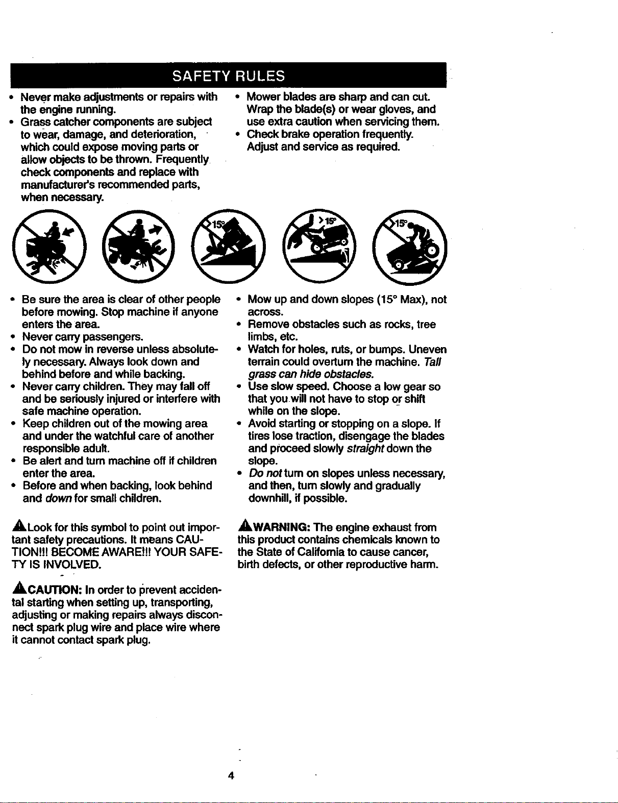
• Mow up and down slopes (15° Max), not
across.
• Remove obstacles such as rocks, tree
limbs, etc.
• Watch for holes, ruts, or bumps. Uneven
terrain could ovedum the machine. Tall
grass can hide obstacles.
• Use slow speed. Cheese a low gear so
that you will not have to stop or shift
while on the slope.
• Avoid starting or stopping on a slope. If
tires lose traction, disengage the blades
and proceed slowly straight down the
slope.
• Do nottum on slopes unless necessary,
and then, turn slowly and gradually
downhill, if possible.
_,Look for this symbol to point out impor-
tant safety precautions. Itmeans CAU-
TlONi!! BECOME AWARE!t! YOUR SAFE-
TY IS INVOLVED.
A --
A CAUTION: In order to prevent acciden-
tal starting when setting up, transporting,
adjusting or making repairs always discon-
nect spark plug wire and place wire where
it cannot contact spark plug.
AWARNING: The engine exhaust from
this product contains chemicals known to
the State of California to cause cancer,
birth defects, or other reproductive harm.
4
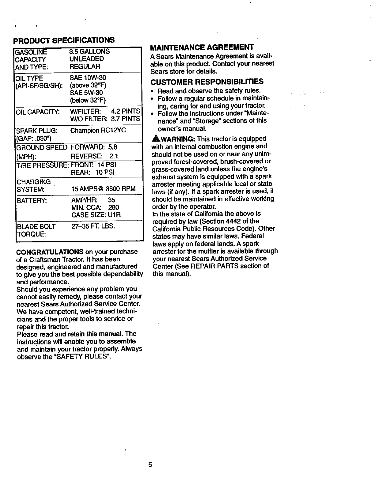
PRODUCT SPECIFICATIONS
_ASOLINE 3.5 GALLONS
;APACITY UNLEADED
qD TYPE: REGULAR
OlLTYPE SAE 10W-30
_,PI-SF/SG/SH): (above 32°F)
SAE 5W-30
(below 32°F)
)IL CAPACITY: W/FILTER: 4.2 PINTS
W/O FILTER: 3.7 PINTS
SPARK PLUG: Champion RC12YC
IGAP: .030")
GROUND SPEED FORWARD: 5.8
(MPH): REVERSE: 2.1
TIRE PRESSURE: FRON'£ 14 PSI
REAR: 10 PSI
CHARGING
;YSTEM: 15 AMPS @ 3600 RPM
BATTERY: AMP/HR: 35
MIN. CCA: 280
CASE SIZE: U1R
BLADE BOLT 27--35 FT. LBS.
TORQUE:
CONGRATULATIONS on your purchase
of a Craftsman Tractor. It has been
designed, engineered and manufactured
to give you the best possible dependability
and performance.
Should you experience any problem you
cannot easily remedy, please contact your
nearest Sears Authorized Service Center.
We have competent, well-trained techni-
cians and the proper tools to service or
repair this tractor.
Please read and retain this manual. The
instructions will enable you to assemble
and maintain your tractor properly. Always
observe the "SAFETY RULES".
MAINTENANCE AGREEMENT
A Sears Maintenance Agreement isavail-
able on this product. Contact your nearest
Sears store for details.
CUSTOMER RESPONSIBIUTIES
• Read and observe the safety rules.
• Follow a regular schedule in maintain-
ing, caring for and using your tractor.
• Follow the instructions under "Mainte-
nance" and "Storage" sections of this
owner's manual.
A, WARNING: This tractor is equipped
with an intemal combustion engine and
should not be used on or near any unim-
proved forest-covered, brush-covered or
grass-covered land unless the engine's
exhaust system is equipped with a spark
arrester meeting applicable local or state
laws (if any). If a spark arrester is used, it
should be maintained in effective working
order by the operator.
In the state of California the above is
required by law (Section 4442 of the
Califomia Public Resources Cede). Other
states may have similar laws. Federal
laws apply on federal lands. A spark
arrester for the muffler is available through
your nearest Sears Authorized Service
Center (See REPAIR PARTS section of
this manual).
5
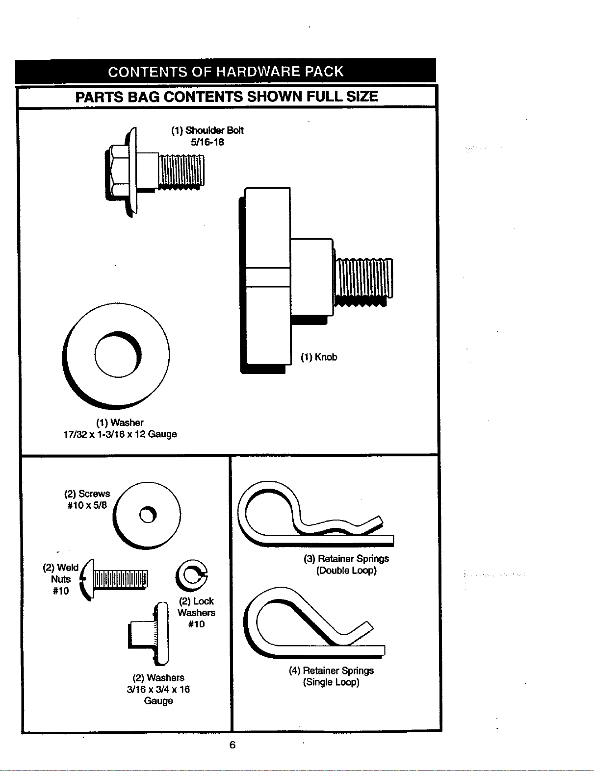
PARTS BAG CONTENTS SHOWN FULL SIZE
t (1) Shoulder Bolt
5/16-18
(1) Washer
17/32 x 1-3/16 x 12 Gauge
,.i.m
/
(1) Knob
(2) Screws @
#10x5/8
I
(2) @
Nuts a _
#10 l_t ,--, (2) Lock
_ Washem
#10
Id
(2) Washers
3/16 x 3/4 x 16
Gauge
(3) RetainerSpdngs
(Double Loop)
(4)RetainerSpdngs
(Single Loop)
6
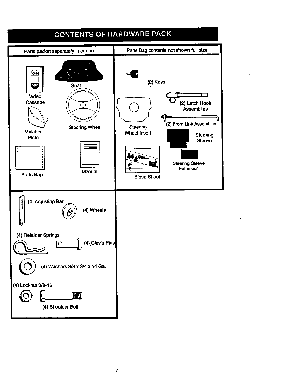
Parts packet separately in carton
I-7
Video
Casse_e
Mulcher
Plate
J
i
i
Parts Bag
Seat
Steering Wheel
h
Manual
i (4) Adjusting Ba_ (4) Wheels
(4) Retainer Springs
_ [_ (4) Clevis Pins
(4) Washers 3/8 x 3/4 x 14 Ga.
(4) Locknut 3/8-16
@D []
(4) Shoulder Bolt
Parts Bag contents not shown full size
4
(2) Keys
(_" "i"_ I I I
('_ (2) Latch Hook
i Assemblies
Steering (2) FrontLinkAssemblies
Wheel Insert Steering
Sleeve
SteeringSleeve
Extension
Slope Sheet
7
Yournewtractorhasbeenassembledatthefactorywithexceptionofthosepartsleft
unassembledfor shippingpurposes.Toensuresafeandproperoperationofyourtractor
all partsandhardwareyouassemblemustbetightenedsecurely.Usethecorrecttools
as necessary to insure proper tightness. Review the video cassette before you begin.
TOOLS REQUIRED FOR
ASSEMBLY
A socket wrench set will make assembly
easier. Standard wrench sizes you need
are listed below.
(1) 9/16" wrench (1) 3/4" Socket w/
(1) 1/2" wrench drive ratchet
(1) Utility knife (1) Phillips Screw-
(1)Pliers driver
(1) Tire pressure gauge
When dght or left hand is mentioned in
this manual, it means, from your point of
view, when you are in the operating posi-
tion (seated behind the steering wheel).
TO REMOVE TRACTOR FROM
CARTON
UNPACK CARTON
• Remove all accessible loose parts and
parts boxes from shipping carton (See
page 6).
• Cut, from top to bottom, along lines on
all four comers of shipping carton, and
lay panels flat.
• Remove mower and package materials.
• Check for any additional loose parts or
boxes and remove.
BEFORE ROLLING TRACTOR OFF
SKID
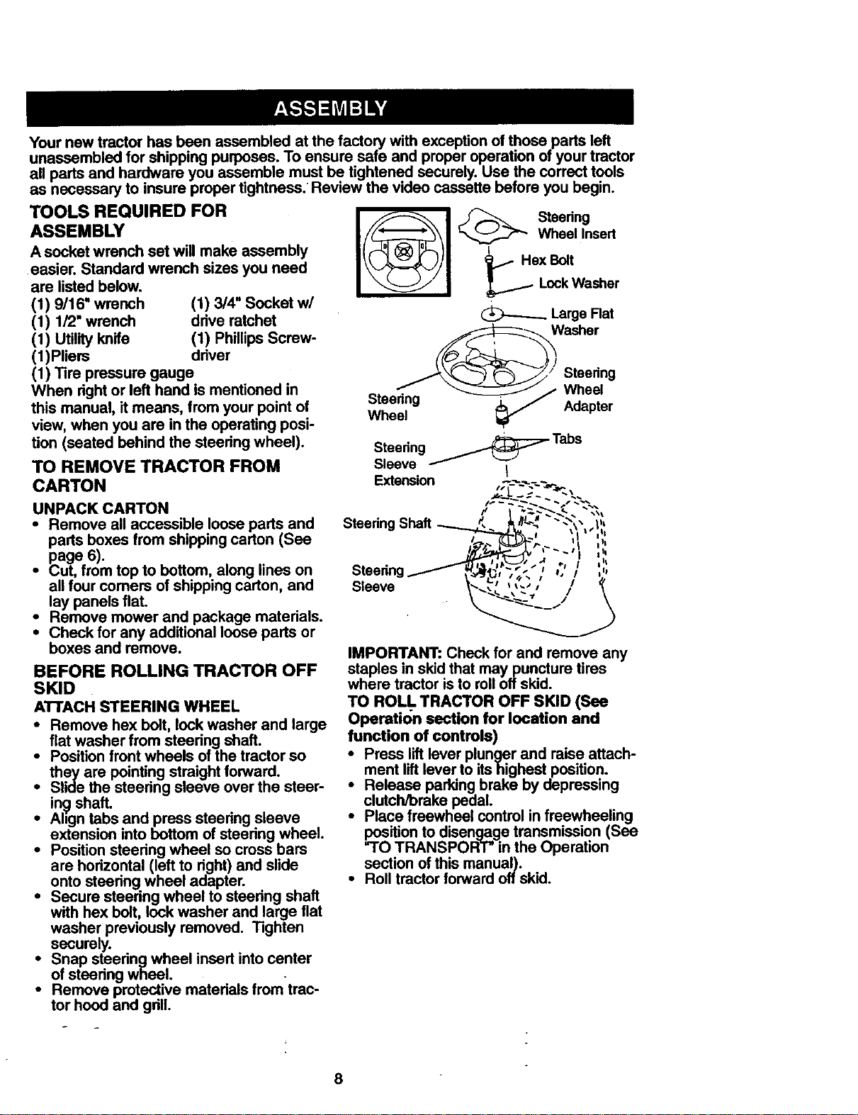
ATTACH STEERING WHEEL
• Remove hex bolt, lock washer and large
flat washer from steering shaft.
• Position front wheels of the tractor so
they are pointing straight forward.
• Slide the steering sleeve over the steer-
in._ shaft.
• Ahgn tabs and press steering sleeve
extension into bottom of steering wheel.
• Position steering wheel so cross bars
are horizontal (left to right) and slide
onto steering wheel adapter.
• Secure steering wheel to steering shaft
with hex bolt, lock washer and large flat
washer previously removed. Tighten
securely.
• Snap steering wheel insert into center
of steering wheel.
• Remove protective materials fromtrac-
tor hood and grill.
=-
_1 Hex Bolt
Lock Washer
Large Flat
Washer
Steering
Wheel
Steering Adapter
Wheel
IMPORTANT: Check for and remove any
staples in skid that may puncture tires
where tractor is to roll off skid.
TO ROLL TRACTOR OFF SKID (See
Operati()n section for location and
function of controls)
• Press lift lever plunger and raise attach-
ment lift lever to itshighest position.
_ elease parking brake by depressing
clutch/brake pedal.
Place freewheel control in freewheeling
_ition to disengage transmission (See
TRANSPORT" in the Operation
section of this manual).
• Roll tractor forward off skid.
8
HOW TO SET UP YOUR TRACTOR
CHECK BATTERY
• Uft hood to raised position.
• Ifthis battery is put into serviceafter
month and year indicated on label (label
located between terminals) charge bat-
tery for minimum of one hour at 6-10
amps. (See "BATTERY" in
MAINTENANCE section of this manual
for charging instructions).
.=--y,' __
.-_" ,." .: Label
,,_....
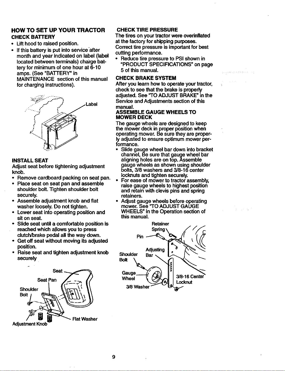
INSTALL SEAT
Adjust seat before tightening adjustment
knob.
• Remove cardboard packing on seat pan.
• Place seat on seat pan and assemble
shoulder bolt.Tighten shoulder belt
securely.
• Assemble adjustment knob and fiat
washer loosely.Do not tighten.
• Lower seat into operating position and
siton seat.
• Slide seat untila comfortable position is
reached which allows you to press
clutch/brake pedal all the way down.
• Get off seat without moving its adjusted
position.
• Raise seat and tighten adjustment knob
securely
Seat
Seat Pan
Shoulder
Bolt
CHECK TIRE PRESSURE
The tires on your tractor were overinflated
at the factory for shipping purposes.
Correct tire pressure is important for best
cutting performance.
• Reduce tire pressure to PSI shown in
"PRODUCT SPECIFICATIONS" on page
5 of this manual.
CHECK BRAKE SYSTEM
After you learn how to operate your tractor,
check to see that the brake is properly
adjusted. See "TO ADJUST BRAKE" in the
Service and Adjustments section of this
manual.
ASSEMBLE GAUGE WHEELS TO
MOWER DECK
The gauge wheels are designed to keep
the mower deck in proper position when
operating mower. Be sure they are proper-
ly adjusted to ensure optimum mower per-
formance.
• Slide gauge wheel bar down into bracket
channel, Be sure that gauge wheel bar
aligning holes are on top. Assemble
gboaUgewheels as shown using shoulder
Its, 3/8 washers and 3/8-16 center
Iocknuts and tighten securely.
• For ease of mower to tractor assembly,
raise gauge wheels to highest position
and retain with clevis pins and spring
retainers.
• Adjust gauge wheels before operating
mower. See "TO ADJUST GAUGE
WHEELS" in the Operation section of
this manual.
Retainer
SpdngX _//_r.
_°lt°U'der _J___
AdjustmentKnob
Rat Washer
9
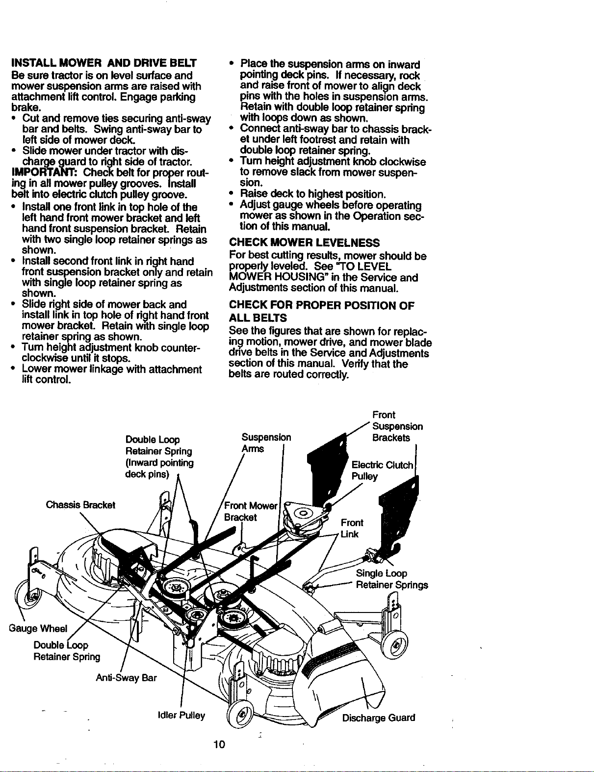
INSTALLMOWERANDDRIVEBELT
Besuretractorison level surface and
mower suspension arms are raised with
attachment lift control. Engage parking
brake.
• Cut and remove ties securing anti-sway
bar and belts. Swing anti-sway bar to
left side of mower deck.
• Slide mower under tractor with dis-
charge guard to right side of tractor.
IMPORTANT: Check belt for proper rout-
ing in all mower pulley grooves. Install
belt into electric clutch pulley groove.
• Install one front link in top hole of the
left hand front mower bracket and left
hand front suspension bracket. Retain
with two single loop retainer springs as
shown.
• Install second front link in righthand
front suspension bracket only and retain
with single loopretainer spring as
shown.
• Slide rightside of mower back and
install link in top hole of ri_.hthand front
mower bracket. Retain with single loop
retainer spdng as shown.
i Tum height adjustment knob counter-
clockwise untilit stops.
Lower mower linkage with attachment
liftcontrol.
• Place the suspension arms on inward
pointing .deck pins. If necessary, rock
ano raise front of mower to ali_n deck
pins with the holes in suspension arms.
Retain with double loop retainer spring
with loops down as shown.
• Connect anti-sway bar to chassis brack-
et under left footrest and retain with
double loop retainer spring.
• Turn height adjustment knob clockwise
to remove slack from mower suspen-
sion.
• Raise deck to highest position.
• Adjust gauge wheels before operating
mower as shown in the Operation sec-
tion of this manual.
CHECK MOWER LEVELNESS
For best cutting results, mower should be
properly leveled. See "TO LEVEL
MOWER HOUSING" in the Service and
Adjustments section of this manual.
CHECK FOR PROPER POSITION OF
ALL BELTS
See the figures that are shown for replac-
ing motion, mower drive, and mower blade
drive belts "nthe Serv=ceand Adjustments
section ofthis manual. Verify that the
belts are muted correctly.
Double Loop
Retainer Spring
(Inward pointing
deck pins)
Suspension
Arms
Front
Brackets
Chassis Bracket
Single Loop
Retainer Springs
Gauge Wheel
Double Loop
Retainer Spring
Anti-Sway Bar
Idler Pulley
10
Discharge Guard
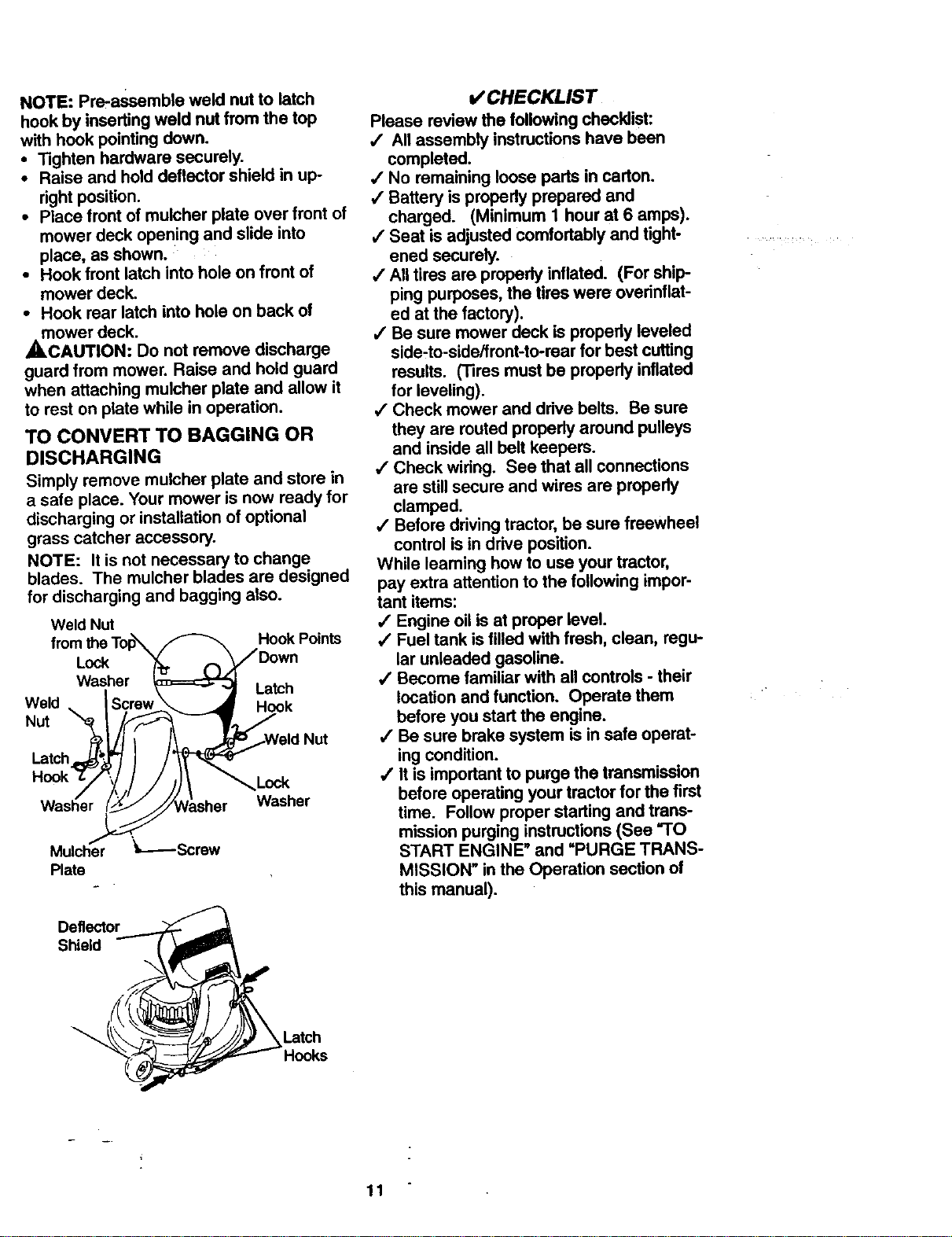
NOTE: Pre-assamble weld nut to latch
hook by inserting weld nut from the top
with hook pointing down.
• Tighten hardware securely.
• Raise and hold deflector shield in up-
right position.
• Place front of mulcher plate over front of
mower deck opening and slide into
place, as shown.
• Hook front latch into hole on front of
mower deck.
• Hook rear latch into hole on back of
mower deck.
,_CAUTION: Do not remove discharge
guard from mower. Raise and hold guard
when attaching mulcher plate and allow it
to rest on plate while in operation.
TO CONVERT TO BAGGING OR
DISCHARGING
Simply remove mulcher plate and store in
a safe place. Your mower is now ready for
discharging or installation of optional
grass catcher accessory.
NOTE: It is not necessary to change
blades. The mulcher blades are designed
for discharging and bagging also,
Weld Nut
Hook Points
Weld
Nut
Lock
Washer
Latch
Hook
Nut
Latch
Washer
Deflector ......_
Shield _'_i
/,, , "---
i Latch
_=>"'- Hooks
_ CHECKLIST
Please review the following checklist:
,/ All assembly instructionshave been
completed.
,/No remaining loose pads in carton.
4 Battery is propedy prepared and
charged. (Minimum 1 hour at 6 amps).
,/Seat is adjustedcomfortably and tight-
ened securely.
/ All tires are properly inflated. (For ship-
ping purposes, the tireswere overinflat-
ed at the factory).
,/Be sure mower deck ispropedy leveled
side-to-side/front-to-rear for best cutting
results. (Tires must be properly inflated
for leveling).
4 Check mower and drive belts. Be sure
they are routed properly around pulleys
and inside all belt keepers.
/ Check widng. See that all connections
are stillsecure and wires are propedy
clamped.
,/Before driving tractor, be sure freewheel
control is in drive position.
While learning how to use your tractor,
pay extra attention to the following impor-
tant items:
,/Engine oil is at proper level.
•/ Fuel tank is filledwith fresh, clean, regu-
lar unleaded gasoline.
•/ Become familiar with all controls- their
location and function. Operate them
before you start the engine.
4' Be sure brake system is in safe operat-
ing condition.
•# It is importantto purge the transmission
before operating your tractor for the first
time. Follow proper starting and trans-
mission purging instructions(See "TO
START ENGINE" and =PURGE TRANS-
MISSION" in the Operation section of
this manual).
w
11
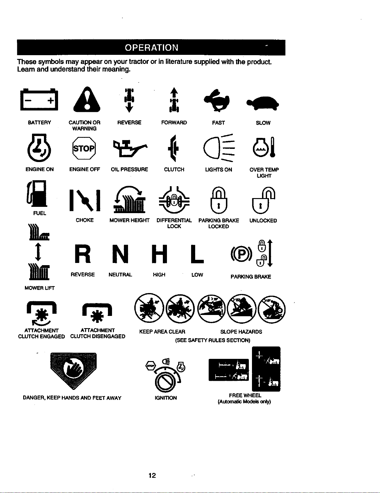
Thesesymbolsmayappearonyourtractororinliteraturesuppliedwiththeproduct.
Leamandunderstandtheirmeaning.
BATTERY CAUTION OR REVERSE FORWARD FAST SLOW
WARNING
ENGINE ON ENGINE OFF OIL PRESSURE CLUTCH LIGHTS ON OVER TEMP
LIGHT
CHOKE MOWER HEIGHT DIFFERENTIAL PARKING BRAKE UNLOCKED
LOCK LOCKED
L
R N H L
REVERSE NEUTRAL HIGH LOW PARKING BRAKE
MOWER UF'I"
ATTACHMENT ATTACHMENT KEEP AREA CLEAR SLOPE HAZARDS
CLUTCH ENGAGED CLUTCH DISENGAGED
(SEE SAFETY RULES SECTION)
DANGER, KEEP HANDS AND FEET AWAY
IGNITION FREEWHEEL
(AutomaticModelsonly)
12
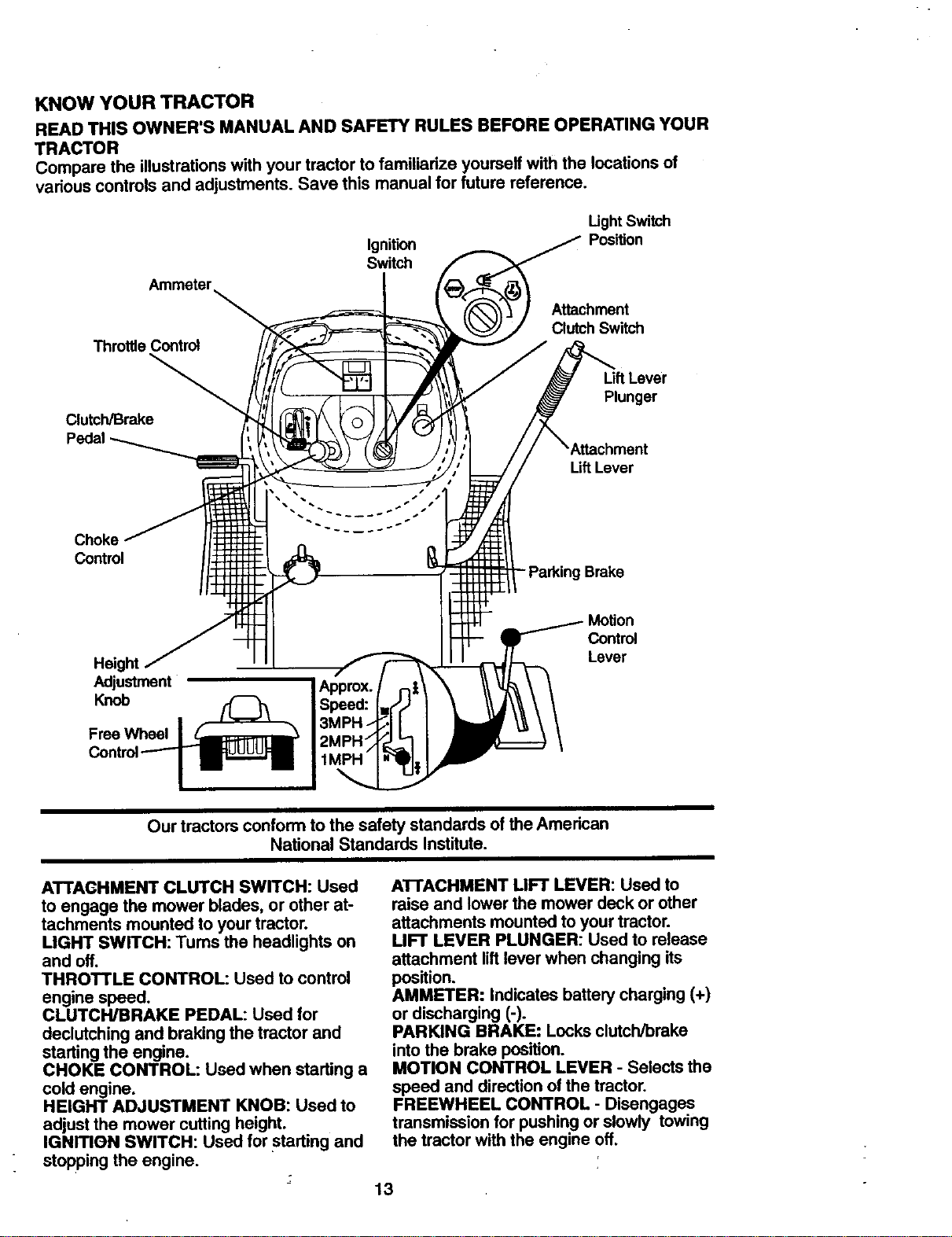
KNOW YOUR TRACTOR
READTHISOWNER'SMANUALANDSAFETYRULESBEFOREOPERATINGYOUR
TRACTOR
Comparetheillustrationswithyourtractortofamiliarizeyourselfwiththelocationsof
variouscontrolsandadjustments.Savethismanualfor future reference.
Ignition
Switch
Light Switch
Pos'dJon
Ammeter
Attachment
Clutch Switch
Throttle Control
LiftLever
Plunger
Clutch/Brake
Pedal
Lift Lever
Control
Brake
Height
Adjustment
Knob
Free Wheel
Control
Lever
Our tractors conform to the safety standards of the American
National Standards Institute.
ATTAGHMENT CLUTCH SWITCH: Used
to engage the mower blades, or other at-
tachments mounted to your tractor.
LIGHT SWITCH: Tums the headlights on
and off.
THROTTLE CONTROL: Used to control
engine speed.
CLUTCH/BRAKE PEDAL: Used for
declutching and braking the tractor and
starting the engine.
CHOKE CONTROL: Used when starting a
cold engine.
HEIGHT ADJUSTMENT KNOB: Used to
adjust the mower cutting height.
IGNmON SWITCH: Used for starting and
stopping the engine.
AI-I'ACHMENT MFT LEVER: Used to
raise and lower the mower deck or other
attachments mounted to your tractor.
LIFT LEVER PLUNGER: Used to release
attachment lift lever when changing its
position.
AMMETER: Indicates battery charging (+)
or discharging (-).
PARKING BRAKE: Locks clutch/brake
into the brake position.
MOTION CONTROL LEVER - Selects the
speed and direction of the tractor.
FREEWHEEL CONTROL - Disengages
transmission for pushing or slowly towing
the tractor with the engine off.
13
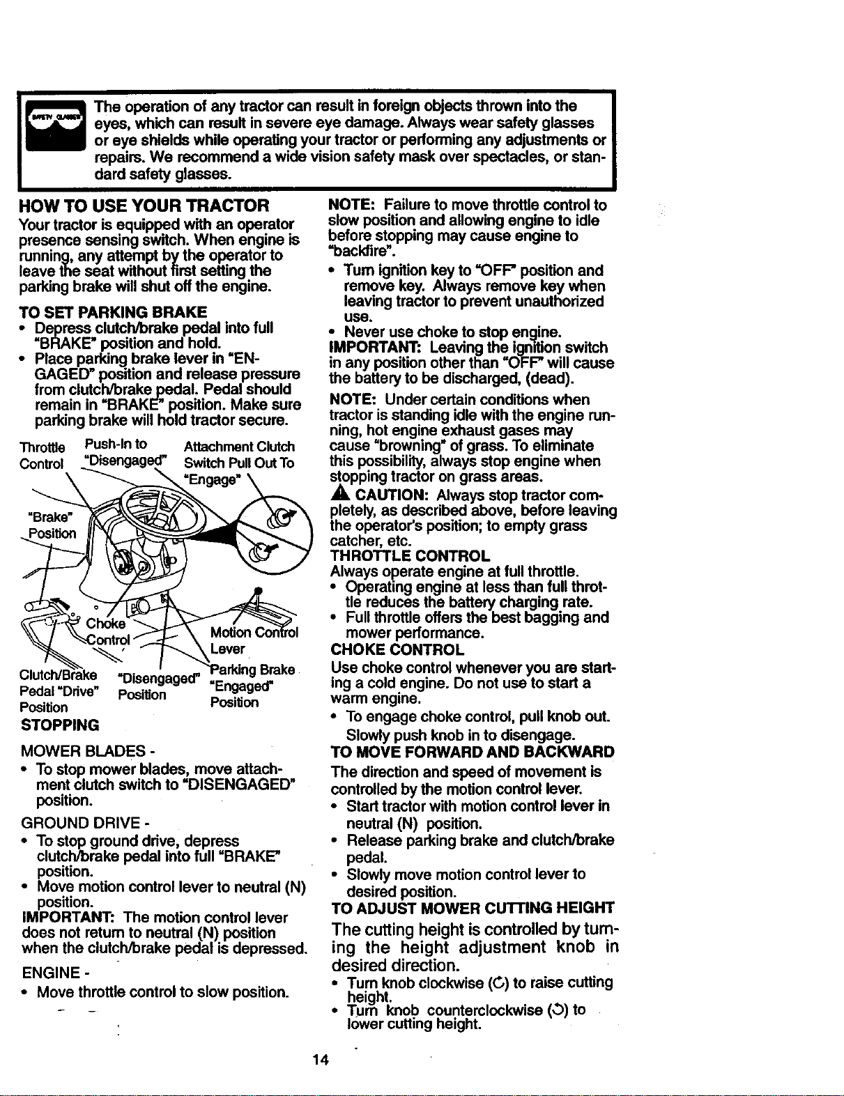
The operation of any tractor can result in foreign objects thrown into the
eyes, which can result insevere eye damage. Always wear safety glasses
or eye shields while operating your tractor or performing any adjustments or
repairs. We recommend a wide vision safety mask over spectacles, or stan-
dard safety glasses.
HOW TO USE YOUR TRACTOR
Your tractor is equipped with an operator
presence sensing switch. When engine is
running,any attempt by the operator to
leave the seat without firstsetting the
parking brake will shutoff the engine.
TO SET PARKING BRAKE
• Depress clutch/brake pedal intofull
=BRAKE"positionand hold.
• Place parking brake lever in "EN-
GAGED" position and release pressure
from clutch/brake pedal. Pedal should
remain in "BRAKE" position. Make sure
parkingbrake will holdtractor secure.
Throttle Push-In to Attachment Clutch
Control =Disengaged" Switch PullOut To
_-__ "Engage"\
Clutch/B'r'ake -Disen 'oa.ed. T arl°:ngBrake
Pedal Dnve Position Engag,_==-,.,_----._-_Y:'_=_" =Enoaoed"
Position Position
STOPPING
MOWER BLADES -
• To stop mower blades, move attach-
ment clutch switch to =DISENGAGED"
position.
GROUND DRIVE -
• To stopground drive, depress
clutch/brake pedal into full "BRAKE"
position.
• Move motion control lever to neutral (N)
position.
IMPORTANT: The motion control lever
does not return to neutral (N) position
when the clutch/brake pedal is depressed.
ENGINE -
• Move throttle control to slow position.
NOTE: Failure to move throttlecontrol to
slow positionand allowing engine to idle
before stoppingmay cause engine to
"backfire".
• Tum ignition key to =OFF" position and
remove key. Always remove key when
leaving tractorto prevent unauthorized
USa.
• Never use choke to stop engine.
IMPORTA...N'r:Leaving the ignitionswitch
in any positionother than "OFF" will cause
the battery to be discharged, (dead).
NOTE: Under certain conditionswhen
tractor isstanding idlewith the engine run-
ning, hot engine exhaust gases may
cause =browning" of grass. To eliminate
this possibility,always stop engine when
stoppingtractor on grass areas.
A CAUTION: Always stop tractor com-
pletely, as describedabove, before leaving
the operator's position;to empty grass
catcher, etc.
THROTTLE CONTROL
Always operate engine at full throttle.
• Operating engine at less than full throt-
tle reduces the battery charging rate.
• Full throttleoffers the bast bagging and
mower performance.
CHOKE CONTROL
Use choke controlwhenever you are start-
ing a cold engine. Do not usa to start a
warm engine.
• To engage choke control, pull knob out.
Slowly push knob in to disengage.
TO MOVE FORWARD AND BACKWARD
The direction and speed of movement is
controlled by the motion control lever.
• Start tractor with motion control lever in
neutral (N) position.
• Release parking brake and clutch/brake
pedal.
• Slowly move motion control lever to
desired position.
TO ADJUST MOWER CUTTING HEIGHT
The cutting height is controlled by tum-
ing the height adjustment knob in
desired direction.
•Tum knob clockwise (G) to raise cutting
height. .
• Turn knoo counterclockwise (,b)to
lowercutting height.
14
Thecuttingheightrangeisapproximately
1-1/2"to 4-1/2".Theheightsaremea-
suredfromthegroundto thebladetipwith
theenginenotrunning.Theseheightsare
approximateandmayvarydependnng
uponsoilconditions,heightof grassand
typesofgrassbeingmowed.
• The average lawn should be cut to
approximately 2-1/2 inches during the
cool season and to over 3 inches during
hot months. For healthier and better
looking lawns, mow often and after
moderate growth.
• For best cutting performance, grass
over 6 inches in height shouldbe
mowed twice. Make the first cut rela-
tively high; the second to desired height.
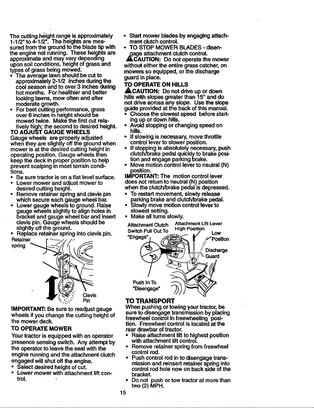
TO ADJUST GAUGE WHEELS
Gauge wheels are properly adjusted
when they are slightly off the ground when
mower is at the desired cutting height in
operating position. Gauge wheels then
keep the deck in proper position to help
prevent scalping in most terrain condi-
tions.
• Be sure tractor is on a flat level surface.
• Lower mower and adjust mower to
desired cutting height.
• Remove retainer spring and clevis pin
which secure each gauge wheel bar.
• Lower gauge wheels to ground. Raise
gauge wheels slightly to align holes in
bracket and gauge wheel bar and insert
clevis pin. Gauge wheels should be
slightly off the ground.
• Replace retainer spring into clevis pin.
Retainer r _//F!_
spring __
Clevis
-. Pin
IMPORTANT: Be sure to readjust gauge
wheels if you change the cutting height of
the mower deck.
TO OPERATE MOWER
Your tractor is equipped with an operator
presence sensing switch. Any attempt by
the operator to leave the seat with the
engine running and the attachment clutch
engaged will shut off the engine.
• Select desired height of cut.
• Lowermower with attachment lift con-
troL
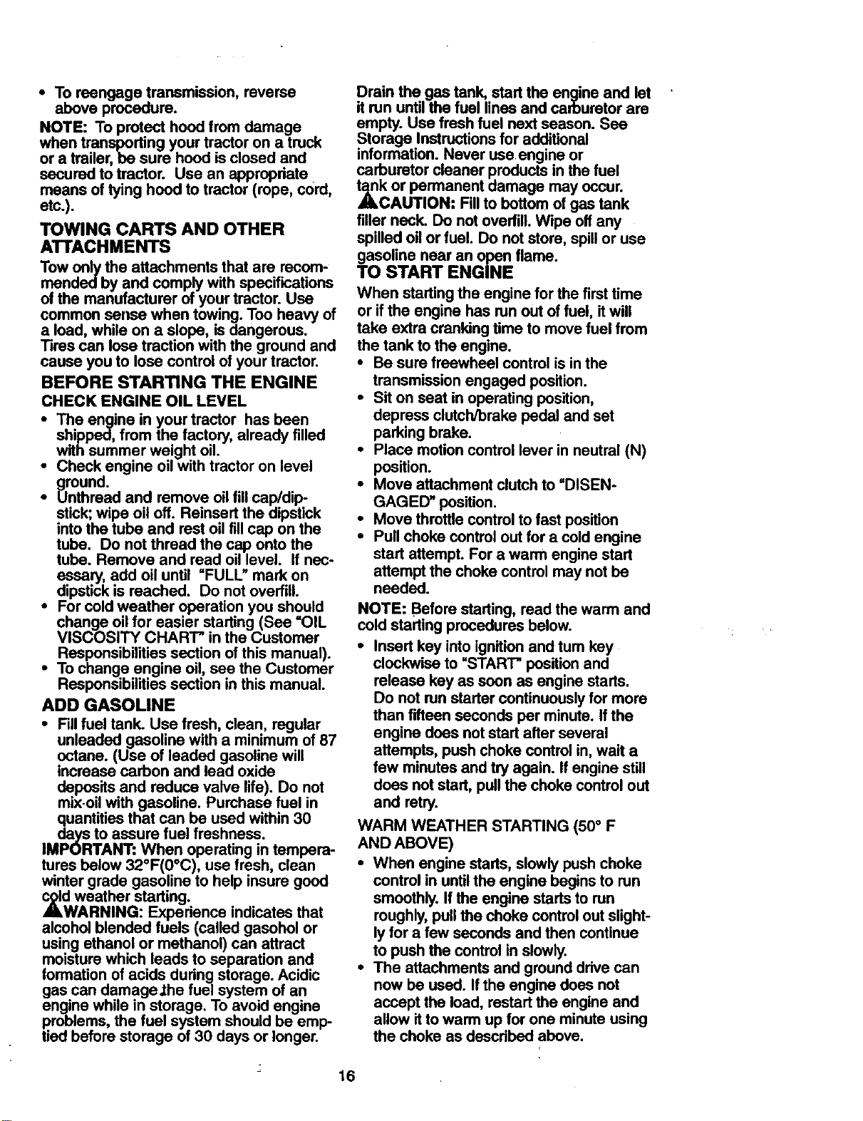
• Start mower blades by engaging attach-
ment clutch control.
• TO STOP MOWER BLADES - disen-
,_ge attachment clutch control.
AUTION: Do not operate the mower
without either the entire grass catcher, on
mowers so equipped, or the discharge
guard in place.
TO OPERATE ON HILLS
_,CAUTION: Do not drive up or down
hills with slopL=sgreater than 15 ° and do
not drive across any slope. Use the slope
guide provided at the back of this manual.
O
Choose the slowest speed before start-
ing up or down hills.
• Avoid stopping or changing speed on
hills.
• If slowing is necessary, move throttle
control lever to slower position.
• If stopping is absolutely necessary, push
clutch/brake pedal quickly to brake posi-
tion and engage parking brake.
• Move motion control lever to neutral (N)
position.
IMPORTANT: The motion control lever
does not return to neutral (N) position
when the clutch/brake pedal is depressed.
To restart movement, slowly release
parking brake and clutch/brake pedal.
Slowly move motion control lever to
slowest setting.
• Make all turns slowly.
Attachment Clutch Attachment Lift Lever
Switch PullOutTo High Position
/ Low
"Engage" __ SfPosition
_' Discharge
"\ Guard
Push In To _ _'_"
=Disengage" "_) )_-
TO TRANSPORT
When pushing or towing your tractor, be
sure to disengage transmission by placing
freewheel control in freewheeling posi-
tion. Freewheel control is located at the
rear drawbar of tractor.
• Raise attachment lift to highest position
with attachment lift control.
• Remove retainer spring from freewheel
control rod.
• Push control rod in to disengage trans-
mission and reinsert retainer spdng into
control rod hole now on back side of the
bracket.
• Do not push or tow tractor at more than
two (2) MPH.
15
• To reengage transmission, reverse
above procedure.
NOTE: To protect hood from damage
when transporting your tractor on a truck
or a trailer, be sure hood is closed and
secured to tractor. Use an appropdate
means of tying hood to tractor (rope, cord,
etc.).
TOWING CARTS AND OTHER
ATTACHMENTS
Tow only the attachments that are recom-
mended by and comply with specifications
of the manufacturer of your tractor. Use
common sense when towing. Too heavy of
a load, while on a slope, is dangerous.
Tires can lose traction with the ground and
cause you to lose control of your tractor.
BEFORE STARTING THE ENGINE
CHECK ENGINE OIL LEVEL
• The engine in your tractor has been
shipped, from the factory, already filled
with summer weight oil.
• Check engine oil with tractor on level
ground.
• Unthread and remove oil fill cap/dip-
stick; wipe oil off. Reinsert the dipstick
into the tube and rest oil fill cap on the
tube. Do not thread the cap onto the
tube. Remove and read oil level. If nec-
essary., add oil until "FULL" mark on
dipstick is reached. Do not overfill.
• For cold weather operation you should
change oil for easier starting (See =OIL
VISCOSITY CHAR'I" in the Customer
Responsibilities section of this manual).
• To change engine oil, see the Customer
Responsibilities section in this manual.
ADD GASOLINE
• Fill fuel tank. Use fresh, clean, regular
unleaded gasoline with a minimum of 87
octane. (Use of leaded gasoline will
increase carbon and lead oxide
deposits and reduce valve life). Do not
mix-oil with gasoline. Purchase fuel in
quantities that can be used within 30
days to assure fuel freshness.
IMPORTANT: When operating in tempera-
tures below 32°F(0°C), use fresh, clean
winter grade gasoline to help insure good
c_ld weather starting.
ALWARNING: Experience indicates that
alcohol blended fuels (called gasohol or
using ethanol or methanol) can attract
moisture which leads to separation and
formation of acids during storage. Acidic
gas can damage,the fuel system of an
engine while in storage. To avoid engine
problems, the fuel system should be emp-
tied before storage of 30 days or longer.
16
Drain the gas tank, start the engine and let
itrun untilthe fuel lines and carburetor are
empty. Use fresh fuel next season. See
Storage Instructionsfor additional
information. Never use engine or
carburetor cleaner products in the fuel
_k or permanent damage may occur.
CAUTION: Fill to bottom of gas tank
filler neck. Do not overfill.Wipe off any
spilled oil or fuel. Do not store, spillor use
gasolinenearanopenflame.
TO START ENGINE
When starting the engine for the first time
or if the engine has run out of fuel, it will
take extra cranking time to move fuel from
the tank to the engine.
• Be sure freewheel control is in the
transmission engaged position.
• Sit on seat in operating position,
depress clutch/brake pedal and set
parking brake.
• Place motion control lever in neutral (N)
position.
• Move attachment clutch to "DISEN-
GAGED" position.
• Move throttle control to fast position
• Pull choke control out for a cold engine
start attempt. For a warm engine start
attempt the choke control may not be
needed.
NOTE: Before starting, read the warm and
cold starting procedures below.
• Insert key into ignitionand tum key
clockwise to "START" positionand
release key as soon as engine starts.
Do not run startercontinuouslyfor more
than fifteenseconds per minute. Ifthe
engine does not start after several
attempts, push choke control in, wait a
few minutes and try again. If engine still
does notstart, pullthe choke control out
and retry.
WARM WEATHER STARTING (50 ° F
AND ABOVE)
• When engine starts, slowly push choke
control in until the engine begins to run
smoothly. If the engine starts to run
roughly, pull the choke control out slight-
ly for a few seconds and then continue
to push the control in slowly.
• The attachments and ground drive can
now be used. If the engine does not
accept the load, restart the engine and
allow it to warm up for one minute using
the choke as descdbed above.
COLD WEATHER STARTING (50 ° F AND
BELOW)
• When engine starts, slowly push choke
control in until the engine begins to run
smoothly. Continue to push the choke
control in small steps allowing the
engine to accept small changes in
speed and load, until the choke control
is fully in. If the engine starts to run
roughly, pull the choke control out slight-
ly for a few seconds and then continue
to push the control in slowly. This may
require an engine warm-up period from
several seconds to several minutes,
depending on the temperature.
AUTOMATIC TRANSMISSION WARM-UP
• Before driving the unit in cold weather,
the transmission should be warmed up
as follows:
• Be sure the tractor is on level ground.
• Place the motion control lever in neu-
tral. Release the parking brake and
let the clutch/brake slowly return to
operating position.
• Allow one minute for transmission to
warm up. This can be done during the
engine warm up period.
• The attachments can be used during
the engine warm-up period after the
transmission has been warmed up and
may require the choke control be pulled
out slightly.
NOTE: A high altitude (above 3000 feet)
or in cold temperatures (below 32 F) the
carburetor fuel mixture may need to be
adjusted for best engine psdormance.
See "TO ADJUST CARBURETOR" in the
Service and Adjustments section of this
manual.
PURGE TRANSMISSION
_,CAUTION: Never engage or disen-
gage freewheel lever while the engine is
running.
To ensure proper operation and perfor-
mance, it is recommended that the trans-
mission be purged before operating tractor
for the first time. This procedure will
remove any trapped air inside the trans-
mission which may have developed during
shipping of your tractor.
IMPORTANT: Should your transmission
require removeal for service or replace-
ment, it should be purged after reinstalla-
tion before operating the tractor.
• Place tractor safely on level surface with
engine off and parking brake set.
• Disengage transmission by placing free-
wheel control in freewheeling position
(See =1"OTRANSPORT" in this section
of manual).
• Sitting in the tractor seat, start engine.
After the engine is running, move throt-
tle control to slow position. With motion
control lever in neutral (N) position,
slowly disengage clutch/brake pedal.
• Move motion control lever to full forward
position and hold for five (5) seconds.
Move lever to full reverse position and
hold for five (5) seconds. Repeat this
procedure three (3) times.
NOTE: During this procedure there will be
no movement of drive wheels. The air is
being removed from hydraulic drive sys-
tem.
• Move motion control lever to neutral (N)
position. Shut off engine and set parking
brake.
• Engage transmission by placing free-
wheel control in driving position (See
=TO TRANSPORT" in this section of
manual).
• Sitting in the tractor seat, start engine.
After the engine is running, move throt-
tle control to half (1/2) speed. With
motion control lever in neutral (N) posi-
tion, slowly disengage clutch/brake
pedal.
• Slowly move motion control lever for-
ward; after the tractor moves approxi-
mately five (5) feet, slowly move motion
control lever to reverse position. After
the tractor moves approximately five (5)
feet return the motion control lever to
the neutral (N) position. Repeat this pro-
cedure with the motion control lever
three (3) times.
• Your tractor is now purged and now
ready for normal operation.
MOWING TIPS
• "13rechains cannot be used when the
mower housing is attached to tractor.
• Mower should be pmpedy leveled for
best mowing performance. See "TO
LEVEL MOWER HOUSING" in the
Service and Adjustments section of this
manual.
17
• The left hand side of mower should be
used for trimming.
• Drive so that clippings are discharged
onto the area that has been cut. Have
the cut area to the right of the tractor.
This will result in a more even distribu-
tion of clippings and more uniform cut-
ting.
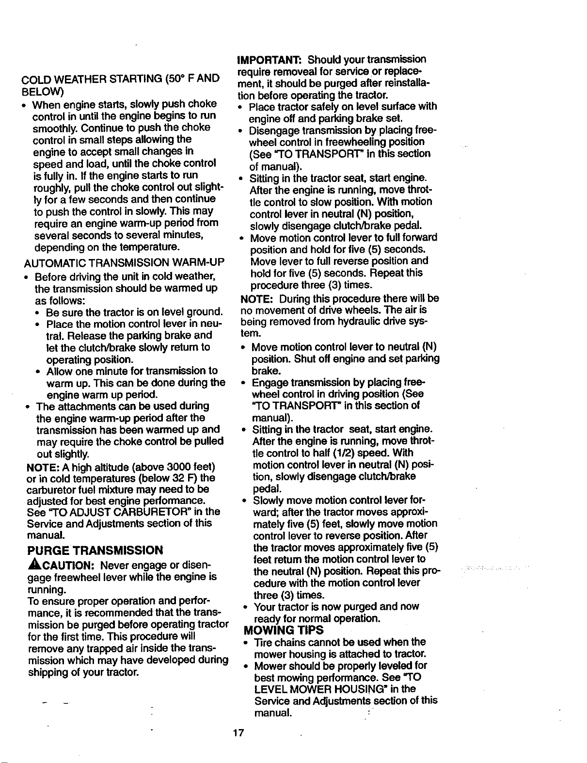
• When mowing large areas, start by turn-
ing to the right so that clippings will dis-
charge away from shrubs, fences, drive_
ways, etc. After one or two rounds, mow
in the opposite direction making left
hand turns until finished.
• If grass is extremely tall, it should be
mowed twice to reduce load and possi- .:
ble fire hazard from dried clippings.
Make first cut relatively high; the second
to the desired height.
• Do not mow grass when it is wet. Wet
grass will plug mower and leave unde-
sirable clumps. Allow grass to dry
before mowing.
• Always operate engine at full throttle
when mowing to assure better mowing
performance and proper discharge of
material. Regulate ground speed by se-
lecting a low enough gear to give the
mower the best cutting performance as
well as the quality of Cut desired.
• When operating attachments, select a
ground speed that will suit the terrain
and give best performance of the at-
tachment being used.
• Avoid cutting your lawn when it is wet,
Wet grass tends to form clumps and
interferes with the mulching action• The
best time to mow your lawn is the early
afternoon. At this time the grass has
dried and the newly cut area will not be
exposed to the direct sun.
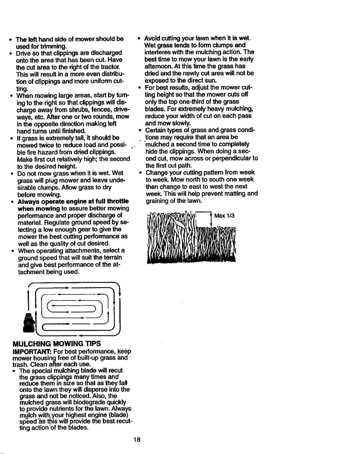
• For best results, adjust the mower cut-
ting height so that the mower cuts off
only the top one-third of the grass
blades. For extremely heavy mulching,
reduce your width of cut on each pass
and mow slowly.
• Certain types of grass and grass condi-
• tions may require that an area be
mulched a second time to completely
hide the clippings. When doing a sec-
ond cut, mow across or perpendicular to
the first cut path.
• Change your cutting pattem from week
to week. Mow north to south one week
then change to east to west the next
week. This will help prevent matting and
graining of the lawn.
i'___'_'_ Max 1/3
I ,z I i', " I w
[
1
t
• ii
J
MULCHING MOWING TIPS
IMPORTANT: For best performance, keep
mower housing free of built-up grass and
trash. Clean after each use.
• The special mulching blade will recut
the grass clippings many times and
reduce them in size so that as they fall
onto the lawn they will disperse into the
grass and not be noticed. Also, the
mulched grass will biodegrade quickly
to provide nutrients for the lawn. Always
mulch witkyour highest engine (blade)
sp-eed-_s t_is will provide the best recut-
ting action of the blades.
18
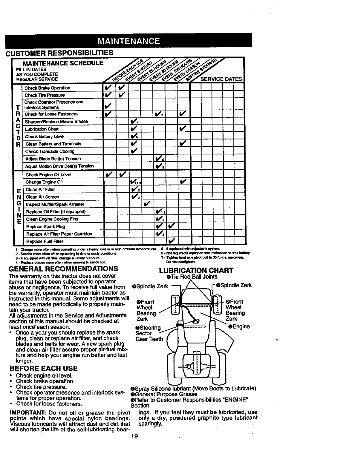
CUSTOMER RESPONSIBILITIES
FILL IN DATES
AS YOU COMPLETE
Check Tim Pr_m
CheckOperatorpresence_
T Inter_ckS,,'aems V'
R CheckforLooseF_enem t/ t/7 t/
A Sharpen/Replace Mower Blades _4
T Lubr_.ationChae ]1/
0 CheckBattep/Level
R CleanBatteP/andTerminals l/
CheckTransaxleCooling I_
AdjustBlade Belt(s) Tension li_s
AdjustMotionDdveBelt(s) Tension I_s
Check Engine OilLevel I##
ChangeEngine_l IV_,3 t/
E i CleanAirFilter i_t_:
N CleanAirScreen
G Inspect Muffler/Spark Attester I_
NI Replace Oil Filter (If equipped) I_1.;
E CteanEngine Cooling Fins _2
Replace Spark Plug _1=
Replace AirFilterPaper Cartridge
Replace FuelFilter
I. Change m_e olten when operat_ under a heavy l_Qd or in high amblenl t_. 5. II e_lipp_l with Iid[ultld=le _.
2. Sei*/Ice mof_ often "/_len oper_ing in didy or dusly coeditiop_.
3 - II equil_ wi_ oUfih¢, changeo_evely50 houm.
4. Replacebladesmornohn whenmo_f_g Inuedy soa.
GENERAL RECOMMENDATIONS
The warranty on this tractor does not cover
items that have been subjected to operator
abuse or negligence. To receive full value from
the warranty, operator must maintain tractor as
instructedin this manual. Some adjustments will
need to be made periodicallyto propedy main-
tain your tractor.
All adjustments in the Service and Adjustments
section of this manual should be checked at
least once-each season.
• Once a year you should replace the spark
_lug, clean or replace air filter, and check
lades and belts for wear. A new spark plug
and clean air filterassure properair-fuel mix-
ture and help your engine run better and last
longer.
BEFORE EACH USE
s. N= mqu_d. _tu_pad_ m_ t_y.
7. Tlghtlmfi_onl_,depf,_tbollto35IL-_,I.maximum.
Donoto_r_hten.
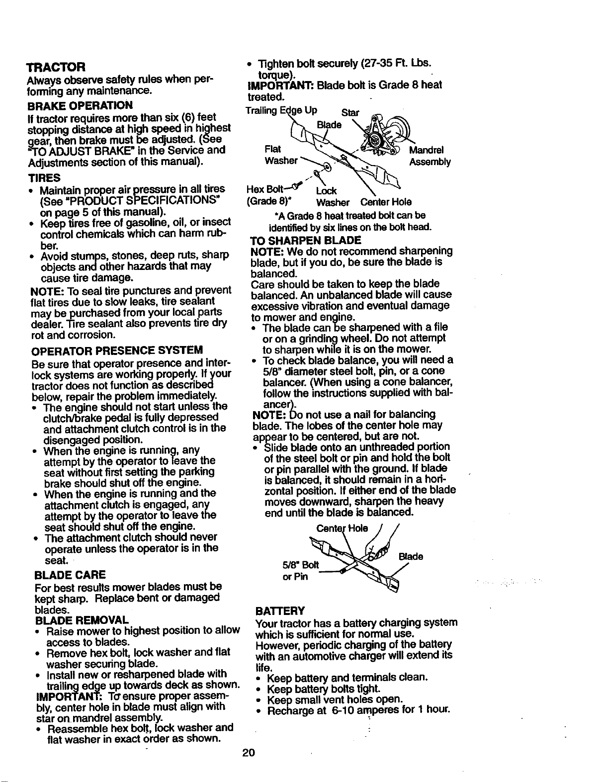
LUBRICATION CHART
O_e Rod BallJoints
. 0n0oZo __ 0 o0oZo
eFront I-_ eFront
Wheel J_r.."-M'_ ...... _ I Wheel
Bearing / _1 _ _|_ Bearing
Zerk _ _..,,. Zerk
eSteering _ I _ eEngine
Sector ff I | I I
Gear Teeth
• Check engine oillevel.
Check brake operation.
• Check tire pressure. _Spray Silicone lubriant(Move Bootsto Lubricate)
• Check operator presence and interlocksys- eGaneral Purpose Grease
ternsfor proper operation. _Refer to Customer Responsibilities"ENGINE"
• Check for loose fasteners. Section
IMPORTANT: Do not oil or grease the pivot ings. If you feel they must be lubricated, use
points--which have special nylon bearings, only a dry, powdered graphite type lubricant
Viscous lubricants will attract dust and dirt that sparingly.
will shorten the life of the self-lubricating bear-
!9
TRACTOR
Always observe safety rules when per-
forming any maintenance.
BRAKE OPERA.ON
If tractor requires mop than six (6) feet
stoppingdistance at high speed in highest
gear, then brake must be adjusted. (See
"TOADJUST BRAKE" in the Service and
Adjustments section of this manual).
TIRES
• Maint=ain proper air pressure in all tires
(See PRODUCT SPECIFICATIONS
on page 5 of this manual).
• Keep tires free of gasoline, oil, or insect
control chemicals which can harm rub-
ber.
• Avoid stumps, stones, deep ruts, sharp
objects and other hazards that may
cause tire damage.
NOTE: To seal tire punctures and prevent
flat tires due to slow leaks, tire sealant
may be purchased from your local parts
dealer. Tire sealant also prevents tire dry
rot and corrosion.
OPERATOR PRESENCE SYSTEM
Be sure that operator presence and inter-
lock systems are working properly. If your
tractor does not function as described
below, repair the problem immediately.
• The engine should not start unless the
clutch/brake pedal is fully depressed
and attachment clutch control is in the
disengaged position.
* When the engine is running, any
attempt by the operator to leave the
seat without first setting the parking
brake should shut off the engine.
• When the engine is running and the
attachment clutch is engaged, an),
attempt by the operator to leave the
seat should shut off the engine.
• The attachment clutch should never
operate unless the operator is in the
seat.
BLADE CARE
For best results mower blades must be
kept sharp. Replace bent or damaged
blades.
BLADE REMOVAL
• Raise mower to highest position to allow
access to blades.
• Remove hex bolt, lock washer and flat
washer securing blade.
• Install new or resharpened blade with
,Mtl_a(_:_/_d_e _p teOn_ua_edSpd_kras,_Own-
bly, center hole in blade must align with
star onmandrel assembly.
• Reassemble hex boW, lock washer and
flat washer in exact order as shown.
• Tighten bolt securely (27-35 R. Lbs.
torque).
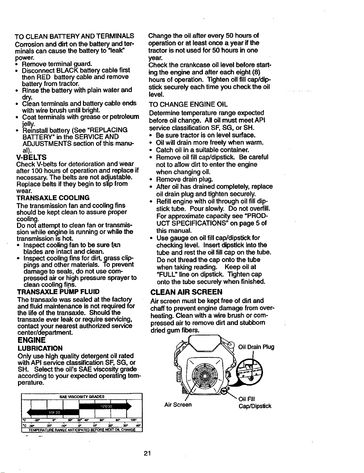
IMPORTANT: Blade boltis Grade 8 heat
treated.
Trailing Star
Flat
Mandrel
Assembly
Hex Bolt----_ Lock
(Grade 8)* Washer Center Hole
*A Grade 8 heat treated boltcan be
identifiedby six lineson the bolthead.
TO SHARPEN BLADE
NOTE: We do not recommend sharpening
blade, but if you do, be sure the blade is
balanced.
Care should be taken to keep the blade
balanced. An unbalanced blade will cause
excessive vibration and eventual damage
to mower and engine.
• The blade canbe sharpened with a file
or on a grinding wheel. Do not attempt
to sharpen while it is on the mower.
• To check blade balance, you will need a
5/8" diameter steel bolt, pin, or a cone
balancer. (When using a cone balancer,
follow the instructions supplied with bal-
ancer).
NOTE: Do not use a nail for balancing
blade. The lobes of the center hole may
appear to be centered, but are not.
• Slide blade onto an unthreaded portion
of the steel bolt or pin and hold the bolt
or pin parallel with the ground. If blade
is balanced, it should remain in a hod-
zontal position. If either end of the blade
moves downward, sharpen the heavy
end until the blade is balanced.
or Pin _ "_
BATTERY
Your tractor has a battery charging system
which is sufficient for normal use.
However, periodic charging of the battery
with an automotive charger will extend its
life.
_Keep battery and terminals clean.
Keep battery bolts tight.
Keep small vent holes open.
Recharge at 6-10 amperes for 1 hour.
2O
TOCLEAN BATTERY AND TERMINALS
Corrosion and dirt on the battery and ter-
minals can cause the battery to "leak"
power.
• Remove terminal guard.
• Disconnect BLACK battery cable first
then RED battery cable and remove
battery from tractor.
• Rinse the battery with plain water and
dry.
• Clean terminals and battery cable ends
with wire brush until bright.
• Coat terminals with grease or petroleum
jelly.
• Reinstall battery (See "REPLACING
BATTERY" in the SERVICE AND
ADJUSTMENTS section of this manu-
al).
V-BELTS
Check V-belts for deterioration and wear
after 100 hours of operation and replace if
necessary. The belts are not adjustable.
Replace belts if they begin to slip from
wear.
TRANSAXLE COOLING
The transmission fan and cooling fins
should be kept clean to assure proper
cooling.
Do not attempt to clean fan or transmis-
sion while engine is running or while the
transmission is hot.
• Inspect cooling fan to be sure fan
blades are intact and clean.
• Inspect cooling fins for dirt, grass clip-
pings and other materials. To prevent
damage to seals, do not use com-
pressed air or high pressure sprayer to
clean cooling fins.
TRANSAXLE PUMP FLUID
The transaxle was sealed at the factory
and fluid maintenance is not required for
the life of the transaxle. Should the
transaxle ever leak or require servicing,
contact your nearest authorized service
center/department.
ENGINE
LUBRICATION
Only use high quality detergent oil rated
with API service classification SF, SG, or
SH. Select the oil's SAE viscosity grade
according to your expected operating tem-
perature.
"20"
TEMPERATURE RANGE ANTICIPATED BEFORE NEXT OIL CHANGE
Change the oil after every 50 hours of
operation or at least once a year if the
tractor is not used for 50 hours in one
year,
Check the crankcase oil level before start-
ing the engine and after each eight (8)
hours of operation. Tighten oil fill cap/dip-
stick securely each time you check the oil
level.
TO CHANGE ENGINE OIL
Determine temperature range expected
before oil change. All oil must meet API
service classification SF, SG, or SH.
• Be sure tractor is on level surface.
• Oil will drain more freely when warm.
• Catch oil in a suitable container.
• Remove oil fill cap/dipstick. Be careful
not to allow dirt to enter the engine
when changing oil.
• Remove drain plug.
• After oil has drained completely, replace
oil drain plug and tighten securely.
• Refill engine with oil through oil fill dip-
stick tube. Pour slowly. Do not overfill.
For approximate capacity see "PROD-
UCT SPECIFICATIONS" on page 5 of
this manual.
• Use gauge on oil fill cap/dipstick for
checking level. Insert dipstick into the
tube and rest the oil fill cap on the tube.
Do not thread the cap onto the tube
when taking reading. Keep oil at
"FULL" line on dipstick. Tighten cap
onto the tube securely when finished.
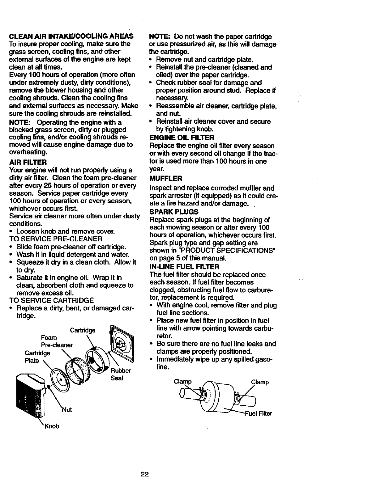
CLEAN AIR SCREEN
Air screen must be kept free of dirt and
chaff to prevent engine damage from over-
heating. Clean witha wire brush or com-
pressed air to remove dirt and stubborn
dried gum fibers.
Oil Drain Plug
• Oil Fill
Air Screen Cap/Dipstick
21
CLEAN AIR INTAKE/COOLING AREAS
To insure proper cooling, make sure the
grass screen, cooling fins, and other
extemal surfaces of the engine are kept
clean at all times.
Every 100 hours of operation (more often
under extremely dusty,dirty conditions),
remove the blower housing and other
cooling shrouds. Clean the cooling fins
and extemal surfaces as necessary. Make
sure the cooling shrouds are reinstalled.
NOTE: Operating the engine with a
blocked grass screen, dirty or plugged
cooling fins, and/or cooling shrouds re-
moved will cause engine damage due to
overheating.
AIR RLTER
Your engine will not run properly using a
dirty air filter. Clean the foam pre-cleaner
after every 25 hours of operation or every
season. Service paper cartridge every
100 hours of operation or every season,
whichever occurs first.
Service air cleaner more often under dusty
conditions.
• Loosen knob and remove cover.
TO SERVICE PRE-CLEANER
• Slide foam pre-cleaner off cartridge.
• Wash it in liquid detergent and water.
• Squeeze it dry in a clean cloth. Allow it
to dry.
• Saturate it in engine oil. Wrap it in
clean, absorbent cloth and squeeze to
remove excess oil.
TO SERVICE CARTRIDGE
• Replace a dirty, bent, or damaged car-
tridge.
Cartridge
Foam
Pre-cleaner
Cartridge
Plate
Rubber
Seal
NOTE: Do not wash the paper cartridge'
or use pressurized air, as this will damage
the cartridge.
• Remove nut and cartridge plate.
• Reinstall the pre-cleaner (cleaned and
oiled) over the paper cartridge.
• Check rubber seal for damage and
proper position around stud. Replace it
necessary.
• Reassemble air cleaner, cartridge plate,
and nut.
• Reinstall air cleaner cover and secure
by tightening knob.
ENGINE OIL FILTER
Replace the engine oil filter every season
or with every second oil change if the trac-
tor is used more than 100 hours in one
year.
MUFFLER
Inspect and replace corroded muffler and
spark arrester (it equipped) as it could cre-
ate a fire hazard and/or damage.
SPARK PLUGS
Replace spark plugs at the beginning of
each mowing season or after every 100
hours of operation, whichever occurs first.
Spark plug type and gap setting are
shown in =PRODUCT SPECIFICATIONS"
on page 5 ofthis manual.
IN-LINE FUEL FILTER
The fuel filter should be replaced once
each season. If fuel filter becomes
clogged, obstructing fuel flow to carbure-
tor, replacement is required.
• With engine cool, remove filter and plug
fuel line sections.
• Place new fuel filter in position in fuel
linewith arrow pointingtowards carbu-
retor.
• Be sure there are no fuel line leaks and
clamps are propedy positioned.
• Immediately wipe up any spilled gaso-
line.
22
CLEANING
• Clean engine, battery, seat, finish, etc.
of all foreign matter•
• Keep finished surfaces and wheels free
of all gasoline, oil, etc.
• Protect painted surfaces with automo-
tive type wax.
We do not recommend using a garden
hose to clean your tractor unless the elec-
trical system, muffler,air filter and carbure-
torare covered to keep water out. Water
in engine can result in a shortened engine
life.
_rCAUTION: Before performing service or adjustments:
any
• Depress clutch/brake pedal fully and set parking brake•
Place motion control lever in neutral (N) position.
• Place attachment clutch in =DISENGAGED" position.
i um ignition key =OFF" and remove key.
Make sure the blades and all moving parts have completely stopped.
Disconnect spark plug wire from spark plug and place wire where it cannot come
in contact with plug.
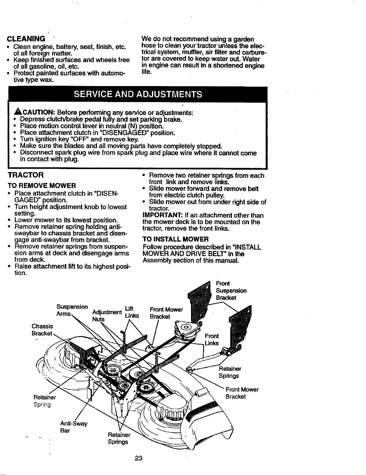
TRACTOR
TO REMOVE MOWER
• Place attachment clutch in =DISEN-
GAGED" position.
• Turn height adjustment knob to lowest
setting
• Lower mower to its lowest position
• Remove retainer spring holding anti-
swaybar to chassis bracket and disen-
gage anti-swaybar from bracket
• Remove retainer springs from suspen-
sion arms at deck and disengage arms
from deck
• Raise attachment lift to its highest posi-
tion
• Remove two retainer springs from each
front link and remove links.
• Slide mower forward and remove belt
from electric clutch pulley.
• Slide mower out from under rightside of
tractor
IMPORTANT: If an attachment other than
the mower deck isto be mounted on the
tractor, remove the front links
TO INSTALL MOWER
Follow procedure described in =INSTALL
MOWER AND DRIVE BELT" in the
Assembly section of this manual•
Front
Chassis
Suspension
Adjustment Lift Front Mower
Nuts Unks Bracket
Bracket
Retainer
Springs
Retainer
Spr;c,g
/
Anti-Sway
Bar
Retainer
Springs
Bracket
23
TOLEVELMOWERHOUSING
Adjustthemowerwhiletractorisperked
onlevelgroundordriveway.Makesure
tiresareproperlyinflated(See"PROD-
UCT SPECIFICATIONS'). If tires are
over or underinflated, you will not propedy
adjust your mower.
SIDE-TO-SIDE ADJUSTMENT
• Raise mower to its highest position.
• Measure height from bottom of deck
cud to ground level at front comers of
mower. Distance "A" on both sides of
mower should be the same.
• If adjustment is necessary, make adjust-
ment on one side of mower only.
• To raise one side of mower, tighten lift
link adjustment nut on that side.
• To lower one side of mower, loosen lift
link adjustment nut on that side.
NOTE: Each full tum of adjustment nut
will change mower height about 3/16".
• Recheck measurements after adjusting.
Bottom
Bottom
otou.\
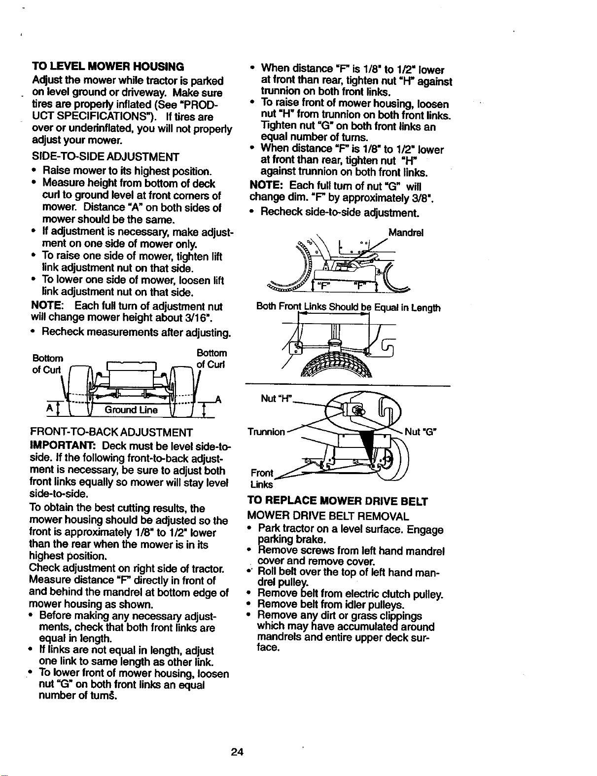
FRONT-TO-BACK ADJUSTMENT
IMPORTANT: Deck must be levelside-to-
side. If the followingfront-to-back adjust-
ment is necessary, be sure to adjustboth
front links equally so mower willstay level
side-to-side.
To obtain the best curing results,the
mower housing should be adjusted so the
front isapproximately 1/8" to 1/2" lower
than the rear when the mower is in its
highest position.
Check adjustment on rightside of tractor.
Measure distance =F"directly in front of
and behind the mandrel at bottom edge of
mower housing as shown.
• Before making any necessary adjust-
ments, check that both front links are
equal in length.
• If links are not equal in length, adjust
one link to same length as other link.
• To lowerfront ofmower housing, loosen
nut "G" on both front links an equal
number of tum_.
• When distance "F_ is 1/8" to 1/2" lower
at front than rear, tighten nut =H" against
trunnion on both front links.
• To raise front of mower housing, loosen
nut "H" from trunnion on both front links.
Tighten nut "(3" on both front links an
equal number of tums.
• When distance "F" is 1/8" to 1/2" lower
at front than rear, tighten nut "H"
against trunnion on both front links.
NOTE: Each full turn of nut "G" will
change dim. "F" by approximately 3/8".
• Recheck side-to-side adjustment.
Mandrel
Both Front LinksShould be Equal in Length
Front
Links
TO REPLACE MOWER DRIVE BELT
MOWER DRIVE BELT REMOVAL
• Park tractor on a level surface. Engage
i_arking brake.
• Remove screws from left hand mandrel
cover and remove cover.
• ' Roll belt over the top of left hand man-
drel pulley.
• Remove belt from electric clutch pulley.
• Remove belt from idler pulleys.
• Remove any dirt or grass clippings
which may have accumulated around
mandrels and entire upper deck sur-
face.
24
• Check pdmary idler arm and two idlers
to see that they rotate freely.
• Be sure spdng is securely hooked to pd-
mary idler arm and bolt in mower hous-
ing.
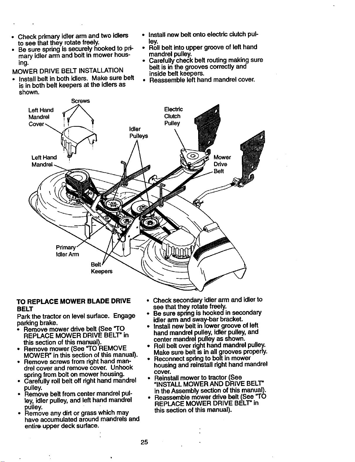
MOWER DRIVE BELT INSTALLATION
• Install belt in both idlers. Make sure belt
is in both belt keepers at the idlers as
shown.
Screws
Left Hand
Mandrel
Cover
Left Hand _P'
• Install new belt onto electdc clutch pul-
ley.
• Roll belt intoupper groove of lefthand
mandrel pulley.
• Carefully check belt routingmaking sure
belt is in the grooves correctly and
inside belt keepers.
• Reassemble left hand mandrel cover.
Electric
Clutch
Pulley
Idler
Pulleys
Prima_
Idler Arm
Belt
Keepers
TO REPLACE MOWER BLADE DRIVE
BELT
Park the tractor on level surface. Engage
parking brake.
• Ren3ove mower drive belt (See "TO
REPLACE MOWER DRIVE BELT" in
this section of this manual).
• Remove mower (Sea "TO REMOVE
MOWER" in this section of this manual).
• Remove screws from right hand man-
drel cover and remove cover. Unhook
spdng from bolt on mower housing.
i arefully roll belt off dght hand mandrel
pulley.
Remove belt from center mandrel pu!
ley, idler pulley, and left hand mandrel
p_uUey.
• Remove any dirt or grass which may
have accumulated around mandrels and
entire upper deck surface.
25
• Check secondary idler arm and idler to
see that they rotate freely.
Be sure spring is hooked in secondary
idler arm and sway-bar bracket.
Install new belt in lower groove of left
hand mandrel pulley, idler pulley, and
center mandrel pulley as shown.
i Roll belt over right hand mandrel pulley.
Make sure belt is in all grooves properly.
Reconnect spdng to bolt in mower
housing and reinstall dght hand mandrel
COVer.
• Reinstall mower to tractor (See
=iNSTALL MOWER AND DRIVE BELT"
in the Assembly section of this manual).
• Reassemble mower drive belt (See "TO
REPLACE MOWER DRIVE BELT" in
this section of this manual).
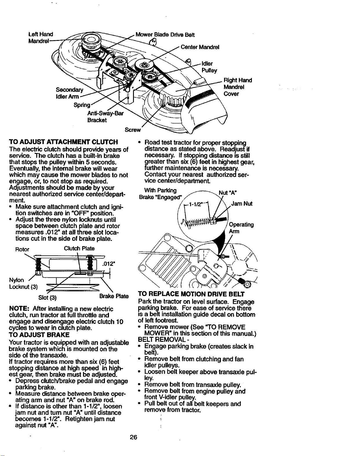
Left Hand Drive Belt
Secondary
Idler Arm
Spring
Anli-Sway-Bar
Bracket
Screw
TO ADJUST ATrACHMENT CLUTCH
The electric clutch should provide years of
service. The clutch has a built-in brake
that stops the pulley within 5 seconds.
Eventually, the intemal brake will wear
which may cause the mower blades to not
engage, or, to not stop as required.
Adjustments should be made by your
nearest authorized service center/depart-
ment.
• Make sure attachment clutch and igni-
tion switches are in "OFF" position.
• Adjust the three nylon Iocknuts until
space between clutch plate and rotor
measures .012" at all three slot loca-
tions cut in the side of brake plate.
Rotor Clutch Plate
Pulley
Right Hand
Mandrel
Cover
• Road test tractor for proper stopping
distance as stated above. Readjust if
necessary. If stopping distance Is still
9reater than six (6)feet in highest gear,
turther maintenance is necessary.
Contact your nearest authodzec] ser-
vice center/department.
Wi_ Parldng _Nut"A"
Brake UEngaged" / "
Jam Nut
.012"
Nylon
Locknut (3)
Slot (3) Brake Plate
NOTE: After installing a new electric
clutch, run tractor at full throttle and
engage and disengage electric clutch 10
cycles towear in clutch plate.
TO ADJUST BRAKE
Your tractor is equipped with an adjustable
brake system which is mounted on the
side of the transaxle.
If tractor requires more than six (6) feet
stopping distance at high speed in high-
est gear, then brake must be adjusted.
• Depress clutch/brake pedal and engage
paddng brake.
• Measure distance between brake oper-
ating arm and nut =A" on brake rod.
• If distance is other than 1-1/2", loosen
jam nut and turn nut =A" until distance
becomes 1-1/2". Retighten jam nut
against nut =A".
TO REPLACE MOTION DRIVE BELT
Park the tractor on level surface. Engage
parking brake. For ease of service there
is a belt installation guide decal on bottom
of left footrest.
• Remove mower (See "TO REMOVE
MOWER" in this section of this manual.)
BELT REMOVAL -
• Engage parking brake (creates slack in
belt).
• Remove belt from clutching and fan
idler pulleys.
• Loosen belt keeper above transaxle pul-
ley.
• Remove belt from transaxle pulley.
Remove belt from engine pulley and
front V-idler pulley.
• Pull bolt out of all belt keepers and
remove from tractor.
26
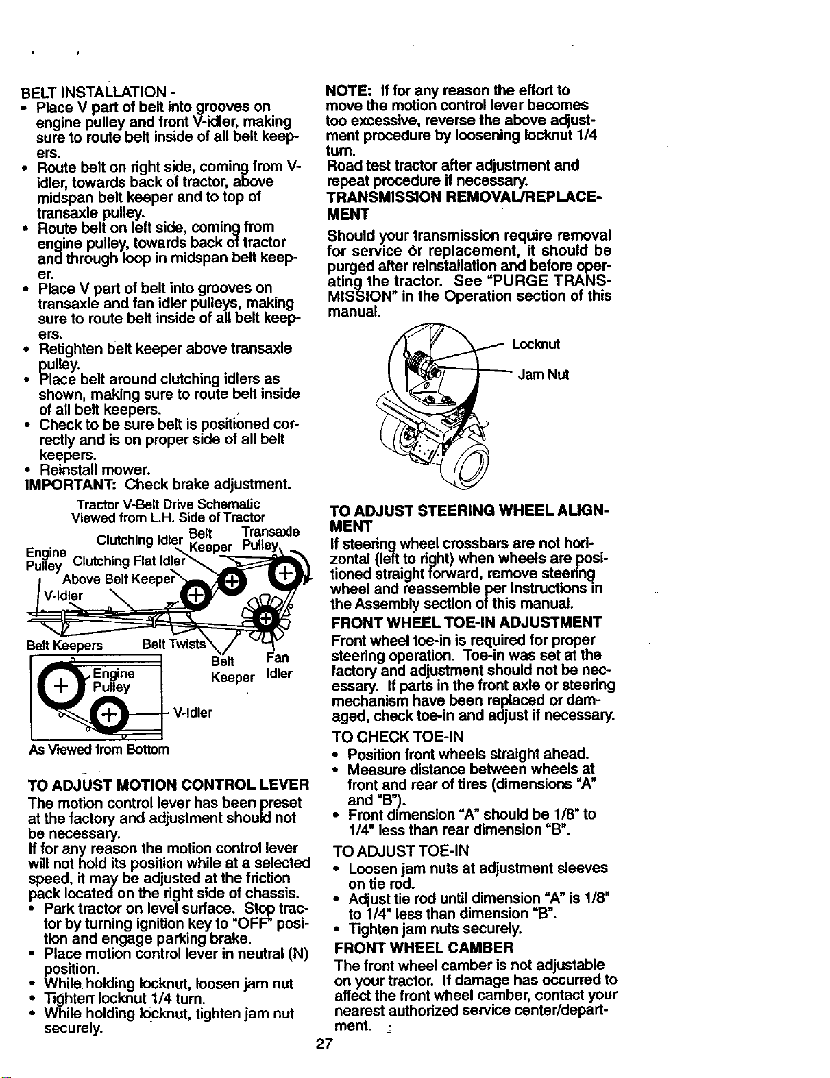
BELTINSTALLATION-
• Place V part of belt intogrooves on
engine pulley and front V-idler, making
sure to route belt inside of all belt keep-
ers.
• Route belt on right side, coming from V-
idler, towards back of tractor, above
midspan belt keeper and to top of
transaxle pulley.
• Route belt on left side, coming from
engine pulley, towards back of tractor
and through loop in midspan belt keep-
er.
• Place V part of belt into grooves on
transaxle and fan idler pulleys, making
sure to route belt inside of all belt keep-
ers.
• Retighten belt keeper above transaxle
pulley.
• Place belt around clutching idlers as
shown, making sure to route belt inside
of all belt keepers.
• Check to be sure belt is positioned cor-
recUy and is on proper side of all belt
keepers.
• Reinstall mower.
IMPORTANT: Check brake adjustment.
Tractor V-Belt Drive Schemal_c
Viewed from L.H. Side ofTractor
Belt Transaxle
Keeper
Engine
Pulley Clutching
Belt Keepers
J Belt Fan
j_w_, En.g.ine J Keeper Idler
I
I_ V-Idler
AsViewed from Bottom
TO ADJIJST MOTION CONTROL LEVER
The motion control lever has been preset
at the factory and adjustment should not
be necessary.
If for any reason the motion control lever
will not hold its position while at a selected
speed, it may be adjusted at the friction
pack located on the right side of chassis.
• Park tractor on level surface. Stop trac-
tor by turning ignition key to "OFF" posi-
tion and engage parking brake.
• Place motion control lever in neutral (N)
position.
• While holding Iocknut, loosen jam nut
Tighten- Iocknut 1/4 turn.
While holding I_cknut, tighten jam nut
securely.
NOTE: If for any reason the effort to
move the motion control lever becomes
too excessive, reverse the above adjust-
ment procedure by loosening Iocknut 1/4
turn.
Road test tractor after adjustment and
repeat procedure if necessary.
TRANSMISSION REMOVAL/REPLACE-
MENT
Should y.our transmission require removal
for service 6r replacement, it should be
purged after reinstallation and before oper-
atingthe tractor. See PURGE TRANS-
MISSION" in the Operation section of this
manual.
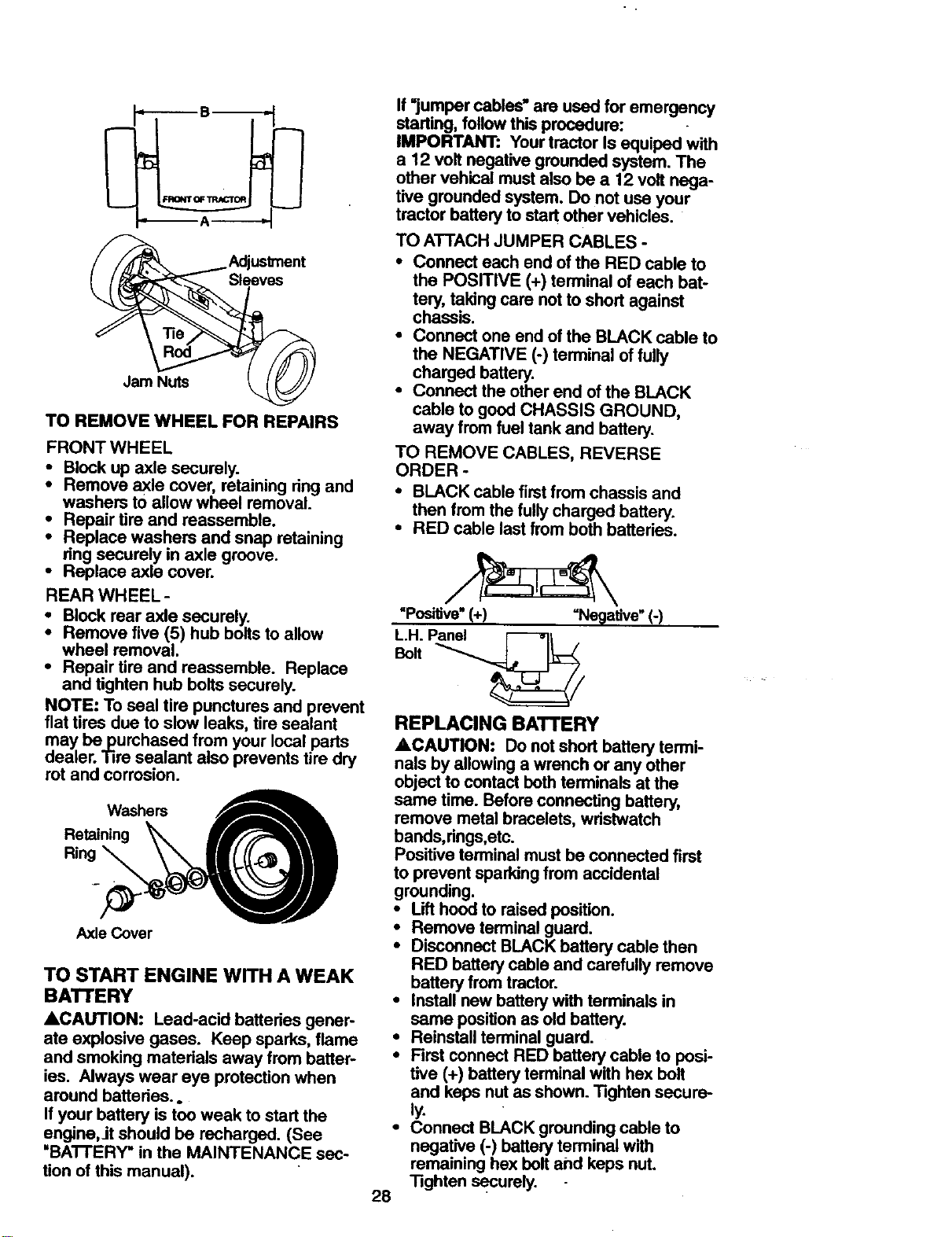
Locknut
Jam Nut
TO ADJUST STEERING WHEEL AUGN-
MENT
ifsteeringwheel crossbars are not hori-
zontal (leftto right) when wheels are posi-
tioned straight forward, remove steerin_l
wheel and reassemble per instructionsm
the Assembly section ofthis manual.
FRONT WHEEL TOE-IN ADJUSTMENT
Front wheel toe-in is required for proper
steering operation. Toe-in was set at the
factory and adjustment should not be nec-
essary. If parts in the front axle or steering
mechanism have been replaced or dam-
aged, check toe-in and adjust if necessary.
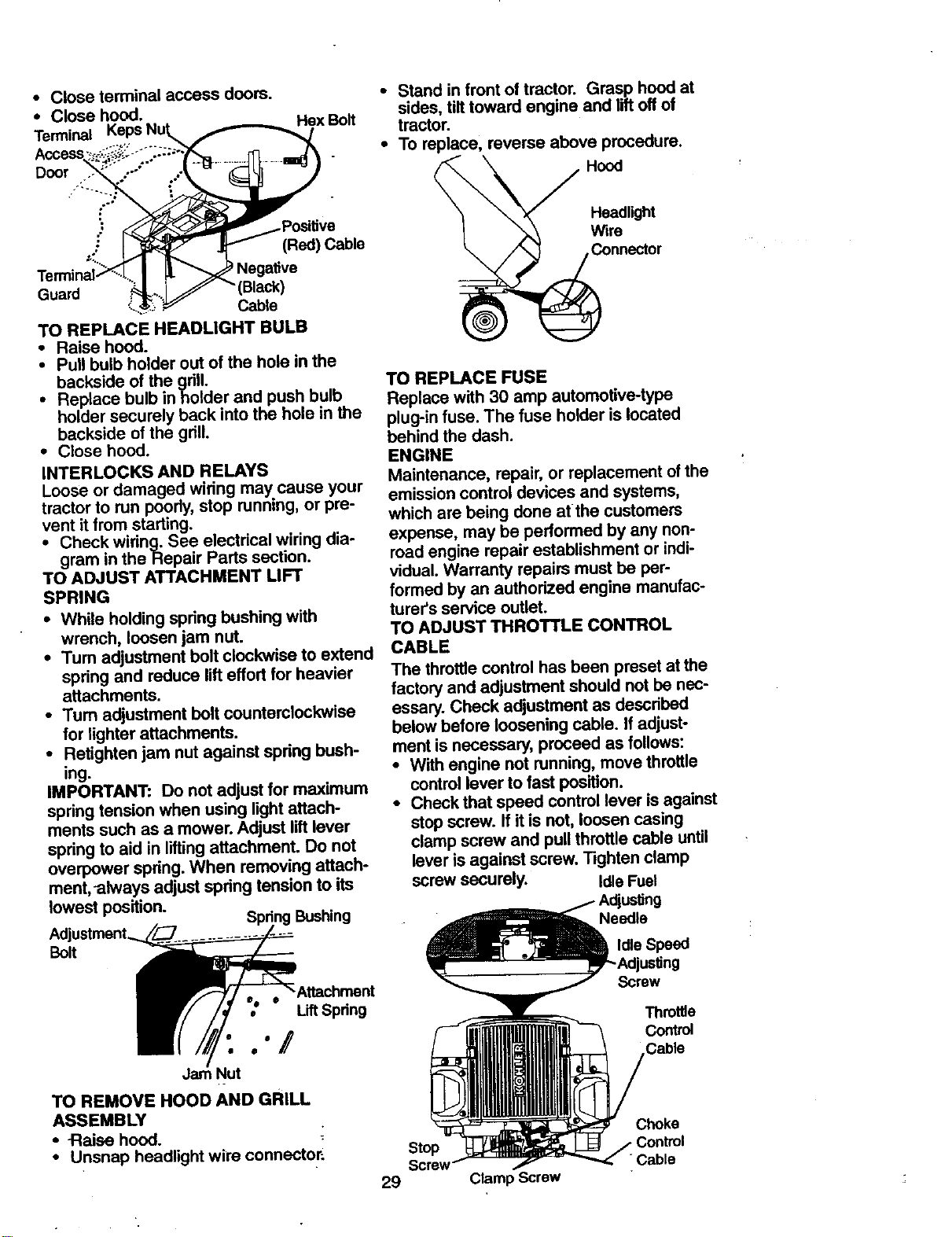
TO CHECK TOE-IN
• Positionfront wheels straight ahead.
• Measure distance between wheels at
front and roar of tires (dimensions =A"
and =B').
• Front dimension "A"should be 118"to
114"less than rear dimension =B".
TO ADJUST TOE-IN
• Loosen jam nuts at adjustment sleeves
on tie rod.
• Adjust tie rod until dimension =A" is 1/8"
to 1/4" less than dimension =B_.
• Tighten jam nuts securely.
FRONT WHEEL CAMBER
The front wheel camber is not adjustable
on your tractor. If damage has occurred to
affect the front wheel camber, contact your
nearest authorized service center/depart-
ment. -
27
Sleeves
Jam Nuts
TO REMOVE WHEEL FOR REPAIRS
FRONT WHEEL
• Block up axle securely.
• Remove axle cover, retaining ring and
washers to allow wheel removal.
• Repair tire and reassemble.
Replace washers and snap retaining
ring securely in axle groove.
• Replace axle cover.
REAR WHEEL -
Block rear axle securely.
Remove five (5) hub bolts to allow
wheel removal.
• Repair tire and reassemble. Replace
and tighten hub bolts securely.
NOTE: To seal tire punctures and prevent
flat tires due to slow leaks, tire sealant
may be purchased from your local parts
dealer. Tire sealant also prevents tire dry
rot and corrosion.
Washers
Retaining _ E_'_I
AxleCover
TO START ENGINE WITH A WEAK
BATTERY
&CAUTION: Lead-acid batteries gener-
ate explosive gases. Keep sparks, flame
and smoking materials away from batter-
ies. Always wear eye protection when
around batteries..
If your battery is too weak to start the
engine,it should be recharged. (See
"BATI'ERY" in the MAINTENANCE sec-
tion of this manual).
If =jumper cables" are used for emergency
starting, follow this procedure:
IMPORTANT: Your tractor Is equiped with
a 12 volt negative grounded system. The
other vehical must also be a 12 volt nega-
tive grounded system. Do not use your
tractor battery to start other vehicles.
TO ATTACH JUMPER CABLES -
• Connect each end of the RED cable to
the POSITIVE (+) terminal of each bat-
tery, taking care not to short against
chassis.
• Connect one end of the BLACK cable to
the NEGATIVE (-) terminal of fully
charged battery.
• Connect the other end of the BLACK
cable to good CHASSIS GROUND,
away from fuel tank and battery.
TO REMOVE CABLES, REVERSE
ORDER -
• BLACK cable first from chassis and
then from the fully charged battery.
• RED cable last from both batteries.
"Positive"(+) =NeQative" (-)
L.H. Panel [_-_qt
REPLACING BATTERY
ACAUTION: Do not short battery termi-
nals by allowinga wrench or any other
object to contact bothterminals at the
same time. Before connecting battery,
remove metal bracelets, wristwatch
bands,rings,etc.
Positive terminal must be connected first
to prevent sparkingfrom accidental
grounding.
• Lift hood to raised position.
• Remove terminal guard.
• Disconnect BLACK battery cable then
RED battery cable and carefully remove
battery fromtractor.
• install new battery with terminals in
same position as old battery.
• Reinstall terminal guard.
• First connect RED battery cable to pesi-
tive (+) battery terminal with hex bolt
and keps nut as shown. Tighten secure-
ly.
• Connect BLACK groundingcable to
negative (-) battery terminal with
remaining hex bolt and keps nut.
Tighten securely.
28
• Close terminal access doors.
• Close hood.
Terminal
Door
Hex Bolt
(Red) Cable
• Stand in front of tractor. Grasp hood at
sides, tilt toward engine and lift off of
tractor.
• To replace, reverse above procedure.
Hood
Headlight
Wire
Connector
Guard
Cable
TO REPLACE HEADUGHT BULB
• Raise hood.
• Pull bulb holder out of the hole in the
backside of the gdll.
• Replace bulb inholder and push bulb
holder securely back into the hole in the
backside of the gdlL
• Close hood.
INTERLOCKS AND RELAYS
Loose or damaged widng may cause your
tractor to run poody, stop running, or pre-
vent it from starting.
• Check wiring. See electrical wiring dia-
gram in the Repair Parts section.
TO ADJUST ATTACHMENT LIFT
SPRING
• While holding spdng bushing with
wrench, loosen jam nut.
• Turn adjustment bolt clockwise to extend
spring and reduce lift effort for heavier
attachments.
• Turn adjustment bolt counterclockwise
for lighter attachments.
• Retighten jam nut against spring bush-
ing.
IMPORTANT: Do not adjust for maximum
spring tension when using light attach-
ments such as a mower. Adjust lift lever
spring to aid in lifting attachment. Do not
overpower spring. When removing attach-
ment, _lways adjust spdng tension to its
lowest position.
Adjustment..
Bolt
TO REPLACE FUSE
Replace with 30 amp automotive-type
plug-in fuse. The fuse holder is located
behind the dash.
ENGINE
Maintenance, repair, or replacement of the
emission control devices and systems,
which are being done at the customers
expense, may be performed by any non-
road engine repair establishment or indi-
vidual. Warranty repairs must be per-
formed by an authorized engine manufac-
turer's service outlet.
TO ADJUST THROTTLE CONTROL
CABLE
The throttlecontrolhas been preset at the
factory and adjustment should not be nec-
essary. Check adjustment as described
belowbefore loosening cable. If adjust-
ment is necessary, proceed as follows:
• With engine not running, move throttle
controllever to fast position.
• Check that speed control lever is against
stopscrew. If itis not, loosen casing
clamp screw and pull throttlecable until
lever is against screw.Tighten clamp
screw securely. IdleFuel
Needle
Idle Speed
, LiftSpdng
°°_
_lut
TO REMOVE HOOD AND GRILL
ASSEMBLY
• -Raise hood.
• Unsnap headlight wire connector;
Step
Screw
29 Clamp Screw
Screw
Throttle
Contr_
Choke
Control
Cable
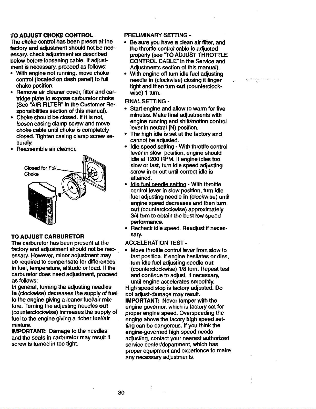
TO ADJUST CHOKE CONTROL
The choke control has been preset at the
factory and adjustment should not he nec-
essary, check adjustment as doscdbed
below before looseningcable. If adjust-
ment is necessary, proceed as follows:
• With engine not running, move choke
control (located on dash panel) to full
choke position.
• Remove air cleaner cover, filter and car-
tddge plate to expose carburetor choke
(See =AIR FILTER" in the Customer Re-
sponsibilitiessection of this manual).
• Choke should he closed. If it isnot,
loosencasing clamp screw and move
choke cable untilchoke is completely
closed. Tighten casing clamp screw se-
curely.
• Reassemble air cleaner.
Closed for
Choke
TO ADJUST CARBURETOR
The carburetor has been present at the
factory and adjustment should not be nec-
essary. However, minor adjustment may
be required to compensate for differences
in fuel, temperature, altitude or load. Ifthe
carburetor does need adjustment, proceed
as follows:
In general, tuming the adjusting needles
in (clockwise) decreases the supply offuel
to the engine giving a leaner fuel/air mix-
ture. Tuming the adjusting needles out
(counterclockwise) increases the supply of
fuel to the engine giving a richerfuel/air
mixture.
IMPORTANT: Damage to the needles
and the seats in carburetor may resultif
screw is turned in too tight.
PRELIMINARY SETTING -
• Be sure you have a clean air filter,and
the throttlecontrolcable is adjusted
properly (see "TO ADJUST THROTTLE
CONTROL CABLE" in the Service and
Adjustments section of this manual).
• With engine off turn idlefuel adjusting
needle in (clockwise) closing it finger
tight and then tum out (counterclock-
wise) 1 tum.
FINAL SETTING -
• Start engine and allow to warm for five
minutes. Make final adjustments with
engine running and shift/motion control
lever in neutral (N) position.
• The high idle is set at the factory and
cannot be adjusted.
• Idle speed settind oWith throttle control
lever in slow position, engine should
idle at 1200 RPM. If engine idles too
slow or fast, tum idle speed adjusting
screw in or out until correct idle is
attained.
• Idle fuel needle settino - With throttle
control lever in slow position, turn idle
fuel adjusting needle in (clockwise) until
engine speed decreases and then turn
out (counterclockwise) approximately
3/4 turn to obtain the best low speed
performance.
• Recheck idle speed. Readjust if neces-
sary.
ACCELERATION TEST -
• Move throttle control lever from slow to
fast position. If engine hesitates or dies,
tum idle fuel adjusting needle out
(counterclockwise) 1/8 tum. Repeat test
and continue to adjust, if necessary,
until engine accelerates smoothly.
High speed stop is factory adjusted. Do
not adjust-damage may result.
IMPORTANT: Never tamper with the
engine govemor, which is factory set for
proper engine speed. Overspeeding the
engine above the facory high speed set-
ting can be dangerous. If you think the
engine-govemed high speed needs
adjusting, contact your nearest authorized
service center/department, which has
proper equipment and experience to make
any necessary adjustments.
30
Immediatelyprepareyourtractorforstor-
ageattheendoftheseasonorifthetrac-
torwillnotbeusedfor 30 days or more.
_,CAUTION: Never store the tractor with
gasoline in the tank inside a building
where fumes may reach an open flame or
spark. Allow the engine to cool before stor-
ing in any enclosure.
TRACTOR
Remove mower from tractor for winter
storage. This will allow you to clean it thor-
oughly. Remove all dirt, grease, leaves,
etc. Store in a clean, dry area.
• Clean entire tractor (See =CLEANING"
in the Maintenance section of this man-
ual).
• Inspect and replace belts, if necessary
(See belt replacement instructions in the
Service and Adjustments section of this
manual).
• Lubricate as shown in the Maintenance
section of this manual.
• Be sure that all nuts, bolts and screws
are securely fastened. Inspect moving
parts for damage, breakage and wear.
Replace if necessary.
• Touch up all rusted or chipped paint sur-
faces; sand lightly before painting.
BATTERY
• Fully charge the battery for storage.
• After a period of time in storage, battery
may require recharging.
• To help prevent corrosion and power
leakage during long periods of storage,
battery cables should be disconnected
and battery cleaned thoroughly (see
='1"OCLEAN BATTERY AND TERMI-
NALS" in the Maintenance section of
this manual).
• After cleaning, leave cables disconnect-
ed and place cables where they cannot
come in contact with battery terminals.
• If battery is removed from tractor for
storage, do not store battery directly on
concrete or damp surfaces.
ENGINE
FUEL SYSTEM
IMPORTANT: It is important to prevent
gum deposits from forming in essential
fuel system parts such as carburetor, fuel
filter, fuel_ose or tank during storage.
Also, experience indicates that alcohol
blended fuels (called gasohol or using
ethanol or methanol) can attract moisture
which leads to separation and formation of
acids during storage. Acidic gas can dam-
age the fuel system of an engine while in
storage.
• Drain the fuel tank.
• Start the engine and let it run until the
fuel lines and carburetor are empty.
• Never use engine or carburetor cleaner
products in the fuel tank or permanent
damage may occur.
• Use fresh fuel next season.
NOTE: Fuel stabilizer is an acceptable
alternative in minimizing the formation of
fuel gum deposits during storage. Add sta-
bilizer to gasoline in fuel tank or storage
container. Always follow the mix ratio
found on stabilizer container. Run engine
at least 10 minutes after adding stabilizer
to allow the stabilizer to reach the carbure-
tor. Do not drain the gas tank and carbure-
tor if using fuel stabilizer.
ENGINE OIL
Drain oil (with engine warm) and replace
with clean engine oil. (See UENGINE" in
the Maintenance section of this manual).
CYLINDER(S)
• Remove spark plug(s).
• Pour one ounce of oil through spark plug
hole(s) into cylinder(s).
•Tum ignition key to =START" position for
a few seconds to distribute oil.
• Replace with new spark plug(s).
OTHER
• Do not store gasoline from one season
to another.
• Replace your gasoline can it it starts to
rust. Rust and/or dirt in your gasoline will
cause problems.
• If possible, store your tractor indoors
and cover it to give protection from dust
and dirt.
• Cover your tractor with a suitable protec-
tive cover that does not retain moisture.
Do not use plastic. Plastic cannot
breathe, which allows condensation to
form and cause your tractor to rust.
IMPORTANT: Never cover tractor while
engine and exhaust areas are still warm.
31
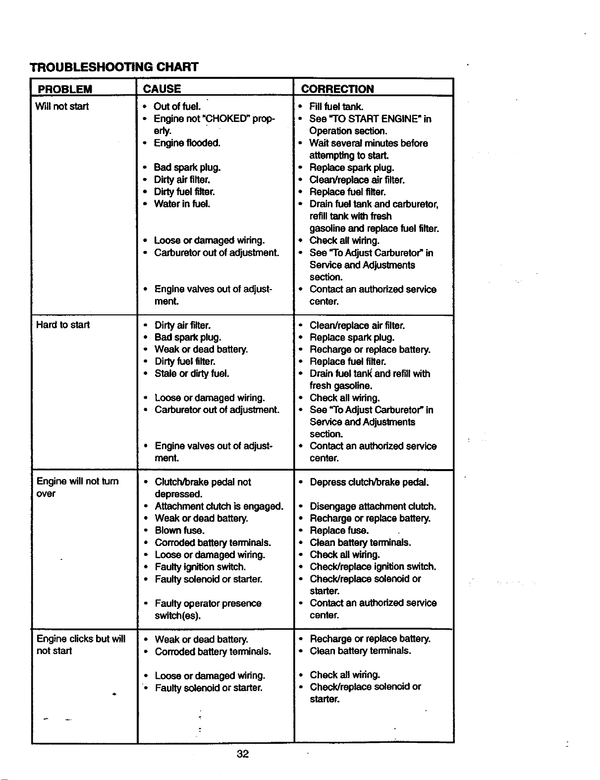
TROUBLESHOOTING CHART
PROBLEM
Willnot start
CAUSE
;- Outoffuel. "
• Engine not "CHOKED" prop-
Hard to start
Engine will not turn
over
Engine clicksbut will
not start
erly.
• Engine flooded.
Io
CORRECTION
J •
• Bad spark plug.
• Dirty air filter.
• Dirtyfuel filter. •
• Water in fuel.
• Loose or damaged widng.
• Carburetor out of adjustment. •
• Engine valves out of adjust- •
menL
• Dirtyair filter.
• Bad spark plug.
• Weak or dead battery.
• Dirtyfuel filter.
• Stale or dirtyfuel.
• Loose or damaged wiring. •
• Carburetorout ofadjustment. •
• Engine valvesout ofadjust- •
ment.
• Clutch/brake pedal not
depressed.
• Attachmentclutchis engaged. .
• Weak or dead battery. *
• Blown fuse. *
• Corroded battery terminals. •
• Loose or damaged widng. •
• Faulty ignitionswitch. •
• Faulty solenoidor starter. •
• Faulty operator presence
switch(es).
• Weak or dead battery. •
• Corroded battery terminals. •
• Loose or damaged widng.
• Faulty solenoid or starter.
Fillfuel tank.
See "TO START ENGINE" in
OperalJonsection.
Wait several minutes before
attempting to start.
Replace spark plug,
Clean/replace air filter.
Replace fuel filter,
Drain fuel tank and carburetor,
refilltank with fresh
gasoline and replacefuel filter.
Check all widng.
See "ToAdjust Carburetor"in
Service and Adjustments
section.
Contact an authorizedservice
center.
Clean/replace air filter.
Replace spark plug.
Recharge or replacebattery.
Replace fuel filter.
Drain fuel tanl_and refillwith
fresh gasoline.
Check all widng.
See "To Adjust Carburetor"in
Service and Adjustments
section.
Contact an authorizedservice
center.
Depress dutch/brake pedal.
Disengage attachment clutch.
Recharge or replacebattery.
Replace fuse.
Clean battery terminals.
Check all wiring,
Check/replace ignitionswitch.
Check/replace solenoidor
starter.
Contact an authorizedservice
center.
Recharge or replace battery.
Clean battery terminals.
Check all widng.
Check/replace solenoid or
starter.
32
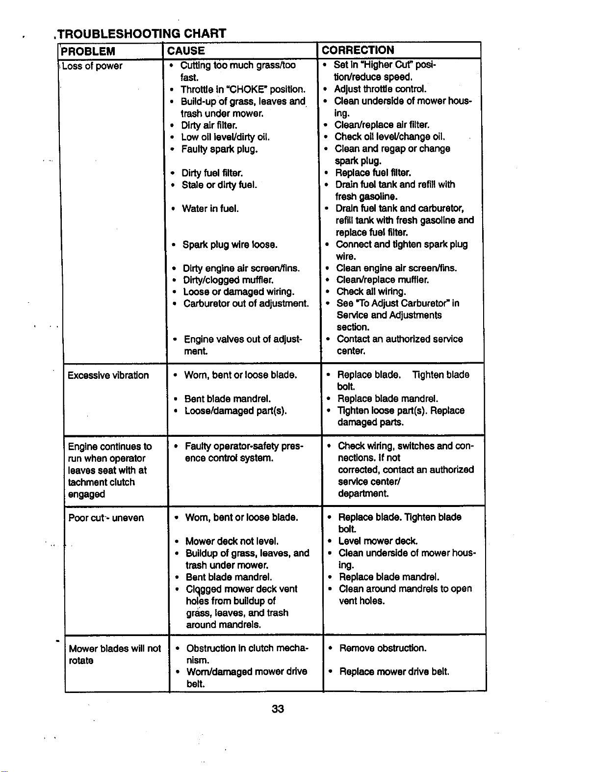
TROUBLESHOOTING CHART
'PROBLEM CAUSE
!Loss of power • Cutting too much grass/too
fast.
• Throttle in "CHOKE" position.
• Build-upof grass, leaves and
trash under mower.
• Dirty air tilter.
• Low oillevel/dirty oil.
• Faulty spark plug.
• Dirtyfuel tilter.
• Stale or dirty fuel.
• Water in fuel.
• Spark plug wire loose.
• Dirty engine air screen/fins.
• Dirty/clogged muffler.
• Loose or damaged widng.
• Carburetor out of adjustment.
• Engine valves out of adjust-
ment.
Excessivevibration • Worn, bent or loose blade.
• Bent blade mandrel.
• Loose/damaged part(s).
Engine continues to • Faultyoperator-safety pres-
runwhen operator ence controlsystem.
leaves seat with at
tachment clutch
engaged
Poor cut-- uneven • Worn, bent or loose blade,
• Mower deck not level.
• Buildupof grass, leaves, and
trash under mower.
• Bent blade mandrel.
• Clogged mower deck vent
holes from buildupof
grass, leaves, and trash
around mandrels.
Mower blades will not • Obstruction in clutchmecha-
rotate nism.
• Wom/damaged mower ddve
belt.
CORRECTION
• Set In "Higher Cut"posi-
tion/reduce speed.
• Adjust throttle control.
• Clean underside of mower hous-
ing.
• Clean/replace air tilter.
• Check oilleveVchange oil.
• Clean and regap or change
spark plug.
• Replace fuel tilter.
• Drain fuel tank and refill with
fresh gasoline.
• Drain fuel tank and carburetor,
refilltank with fresh gasolineand
replace fuel filter.
• Connect and tighten spark plug
wire.
• Clean engine air screervllns.
• Clean/replace muffler.
• Check all wiring.
• See "To Adjust Carburetor"in
Service and Adjustments
section.
• Contact an authorized service
center.
• Replace blade. Tighten blade
bolt.
• Replace blade mandrel.
• Tighten loose part(s). Replace
damaged parts.
• Check wiring, switchesand con-
nections.If not
corrected, contact an authorized
service center/
department.
• Replace blade. Tighten blade
bolt.
• Level mower deck.
• Clean underside of mower hous-
ing.
• Replace blade mandrel.
• Clean around mandrels to open
vent holes.
• Remove obstruction.
• Replace mower drive belt,
33
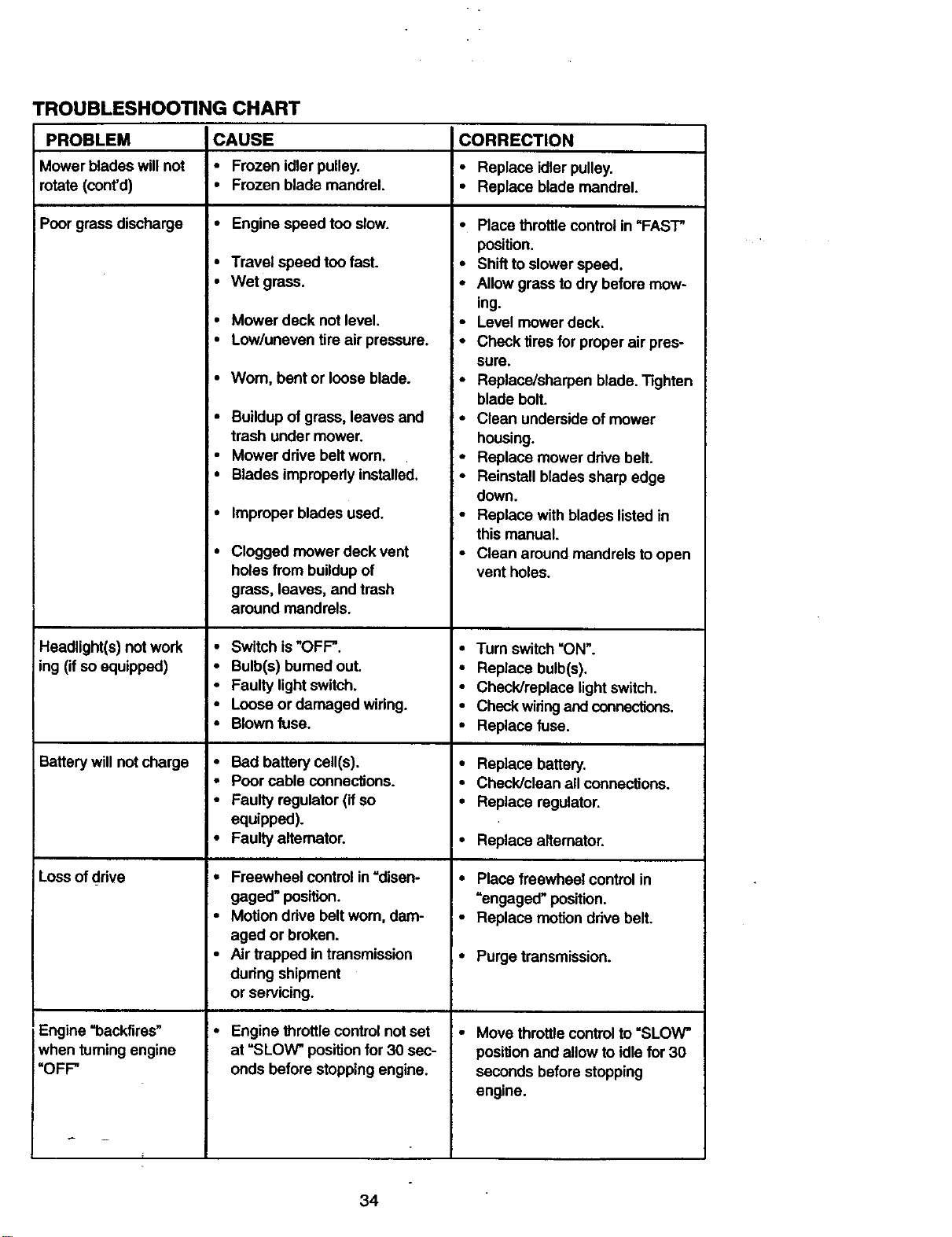
TROUBLESHOOTING CHART
PROBLEM CAUSE CORRECTION
Mower blades willnot • Frozen idler pulley. • Replace idlerpulley.
rotate (cont'd) • Frozen blade mandrel. • Replace blademandrel.
Poor grass discharge • Engine speed too slow.
• Travel speed too fast.
• Wet grass.
Headlight(s) not work •
ing (if so equipped) •
Batterywill not charge •
Loss of drive
Engine =backfires"
when turningengine
"OFF"
• Mower deck not level.
• Low/uneven tire air pressure.
•Wom, bent or loose blade.
• Buildupof grass, leaves and
trash under mower.
• Mower drive belt worn.
• Blades improperlyinstalled.
Improper blades used.
Clogged mower deck vent
holes from buildupof
grass, leaves, and trash
around mandrels.
Switch is "OFF".
Bulb(s) burnedout.
Faulty light switch.
Loose or damaged wiring.
Blown fuse.
Bad battery cell(s).
Poor cable connections.
Faulty regulator (if so
equipped).
Faulty alternator.
Freewheel controlin =disen-
gaged" position.
Motion drive belt wom, dam-
aged or broken.
Air trapped in transmission
during shipment
or servicing.
Engine throttlecontrolnot set
at =SLOW" positionfor 30 sec-
onds before stoppingengine.
• Place throttle controlin "FAST"
position.
• Shift to slowerspeed.
• Allow grass to dry before mow-
ing.
• Level mower deck.
• Check tires for proper air pres-
sure.
• Replace/sharpen blade. Tighten
blade boll
• Clean underside of mower
housing.
• Replace mower drive belt.
• Reinstall blades sharp edge
down.
• Replace with blades listedin
this manual.
• Clean aroundmandrels to open
vent holes.
• Turn switch=ON'.
• Replace bulb(s).
• Check/replace light switch.
• Check wiringand connections.
• Replace fuse.
• Replace battery.
• Check/clean all connections.
• Replace regulator.
• Replace afiemator.
• Place freewheel controlin
=engaged" position.
• Replace motiondrive bell
• Purge transmission.
• Move throttlecontrolto =SLOW"
position and allow to idle for 30
seconds beforestopping
engine.
34
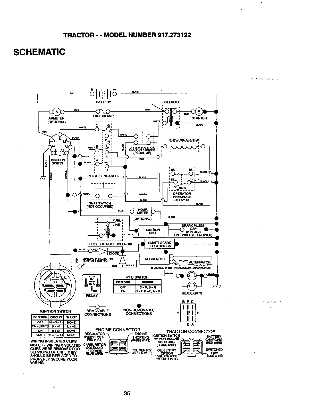
TRACTOR - - MODEL NUMBER 917.273122
SCHEMATIC
_o
BATTERY _D
GFC
o •
IGNITION SWITCH REMOVABLE NON-REMOVABLE
• . CONNECTIONS CONNECTIONS H B
ENGINE CONNECTOR TRA_T("_R_.nNNPP.TnR
REGULATOR "-_ r'-" ENGINE ...................
FUR WIR _ IGNIT_N SWITCH RY
( PLE E. SHORTING BATTE
REDWIRE) RE WIRE M* FOR ENGINE _ CHARGING
W1RING INSULATED CLIPS 0NH ) SHORTING (REDWIRE)
]it'll r_-111
NOTE: IFWlRING INSULATED CARBURETOR (IBLAGKWtRE)
_E_ o,LsE,_o,Ls_ _wITCH_
SHOULDSERVICINGBEOFREPLACEDUNIT, THEYTO _.UE WIREi BEENWIRE) . (y=?zp"_O_wlRE RE)
PROPERLY SECURE YOUR TOLIGHTPKG.)
WIRING.
35
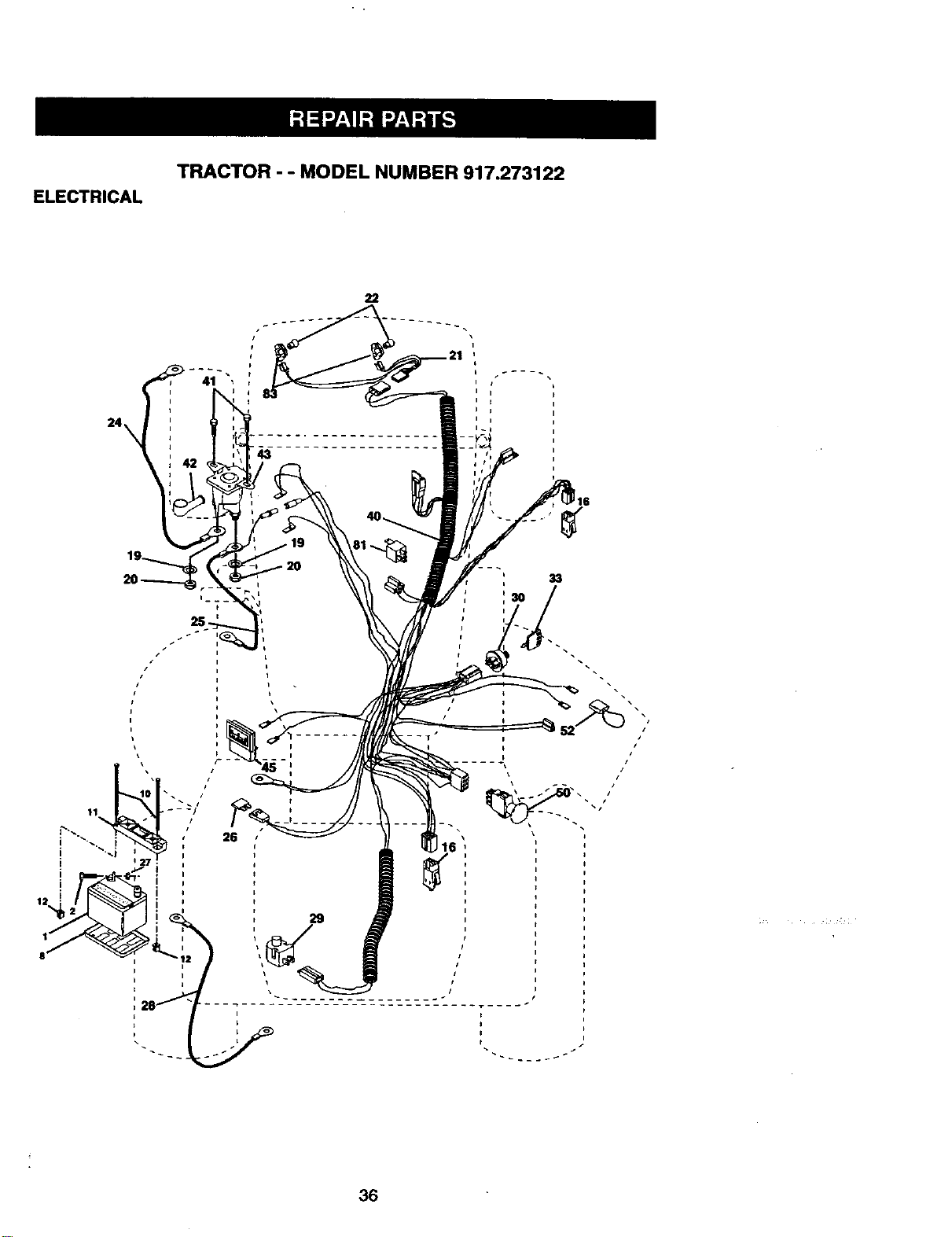
ELECTRICAL
TRACTOR - - MODEL NUMBER 917.273122
22
33
I
i '..i
! i
26
52 /
12 ! i
36
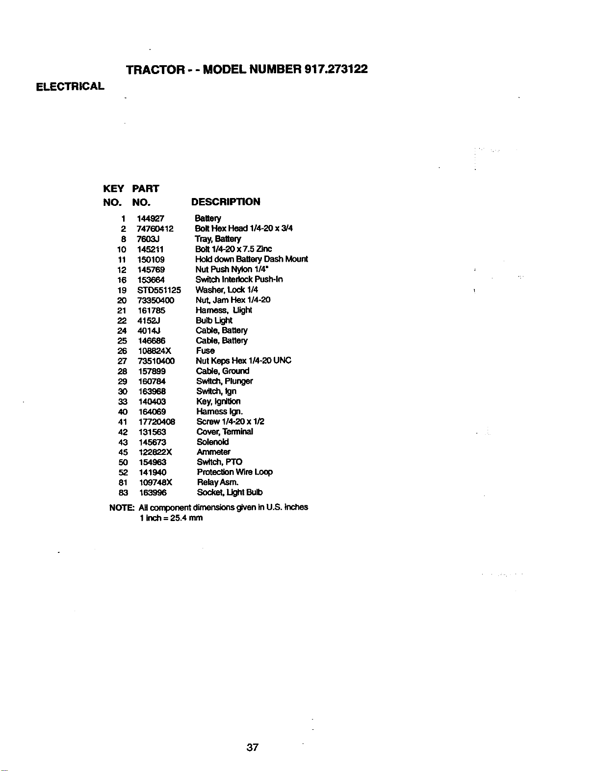
ELECTRICAL
TRACTOR - - MODEL NU MBER 917.273122
KEY PART
NO. NO. DESCRIPTION
1 144927 Batte_j
2 74760412 BoltHex Head 1/4-20 x 3/4
8 7603J Tray, Battery
10 145211 Bolt114-20x 7.5 Zinc
11 150109 HolddownBatteryDashMount
12 145769 Nut PushNylon 1/4"
16 153664 SwitchInterlockPush-In
19 STD551125 Washer,Lock 1/4
20 73350400 Nut,Jam Hex 1/4-20
21 161785 Harness, Might
22 4152J BulbLight
24 4014J Cable, Battely
25 146686 Cable, Battery
26 108824X Fuse
27 73510400 Nut KepsHex 1/4-20 UNC
28 157899 Cable, Ground
29 160784 Switch,Plunger
30 163968 Switch,Ign
33 140403 Key,Ignition
40 164069 Hamess Ign.
41 177_ Screw 1/4-20 x 1/2
42 131563 Cover,Terminal
43 145673 Solenoid
45 122822X Ammeter
50 154963 Switch, PTO
52 141940 ProtectionWire Loop
81 109748X RelayAsm.
83 163996 Socket,LightBulb
NOTE:
Allcomponentdimensionsgivenin U.S. inches
1 inch= 25.4 mm
37
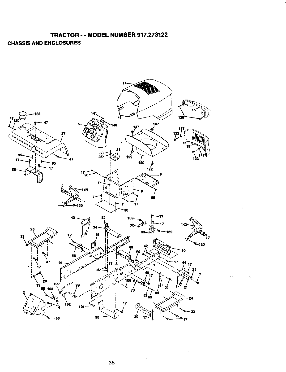
TRACTOR - - MODEL NUMBER 917.273122
CHASSIS AND ENCLOSURES
37
19 100
68
2
17 144
17
17
52
102
56
7O
39
3B
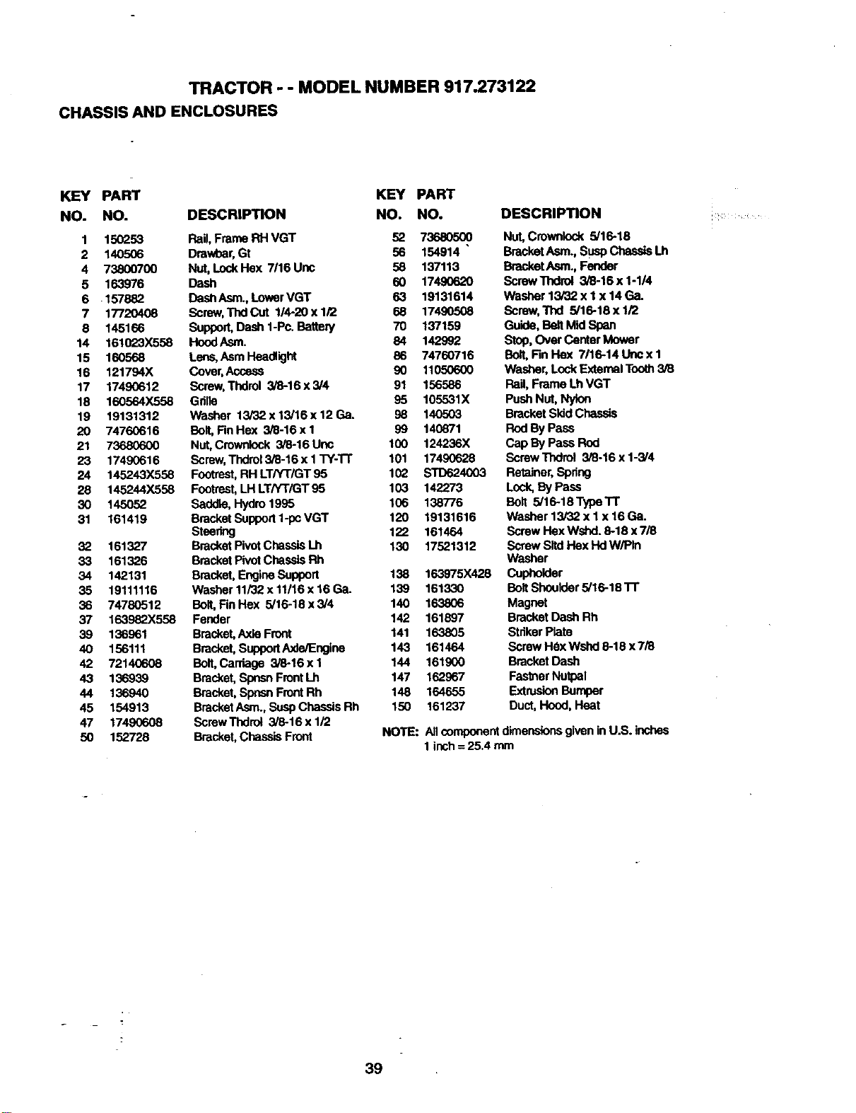
TRACTOR - - MODEL NUMBER 917.273122
CHASSIS AND ENCLOSURES
KEY PART KEY PART
NO. NO. DESCRIPTION NO. NO.
1 150253 Rail, Frame RH VGT 52 73680500
2 140506 Dmwbar,Gt 56 154914 "
4 73800700 Nut, LockFlex 7/16 Unc 58 137113
5 163976 Dash 60 17490620
6 157882 DashAsm.,LowerVGT 63 19131614
7 17720408 Screw,TndCut 114-20xl/2 68 17490508
8 145166 SuppoR,Dash 1-Pc. Battery 70 137159
14 161023X558 HoodAsm. 84 142992
15 160568 Lens,Asm Headlight 86 74760716
16 121794X Cover,Access 90 11050600
17 17490612 ScmwoThdrol 3/8-16x3/4 91 156586
18 160564X558 Gdlle 95 105531X
19 19131312 Washer 13/32x13/16x 12Ga. 96 140503
20 74760616 Bolt,Rn Hex 3/8-16 x I 99 140_T/1
21 73680600 Nut,Crownlock 3/8-16 Unc 100 124236X
23 17490616 Screw,Thdro13/8-16x1TY-'1-r 101 17490628
24 145243X558 Footrsst,FIHLT/YT/GT95 102 STD624003
28 145244X558 Footrest,LHLT/YT/GT 95 103 142273
30 145052 Sadole, Hydro1995 106 138776
31 161419 BracketSupport1-pc VGT 120 19131616
Steering 122 161464
32 161327 Bracket PivotChassisLh 130 17521312
33 161326 Bracket PivotChassislab
34 142131 Bracket,EngineSupport 138 163975X428
35 19111116 Washer11/32 x11/16 x 16Ga. 139 161330
36 74780512 Bolt, FinHex 5/16-16x3/4 140 163806
37 163982X558 Fender 142 161897
39 136961 Bracket,AkieFront 141 163805
40 156111 Brad(el, Supp_lAxJe/Engine 143 161464
42 72140608 Bolt, Carriage 3/8-16 x 1 144 161900
43 136939 Bracket,Spnsn FrontLh 147 162967
44 136940 Bracket,SpnsnFrontRh 148 164655
45 154919 BracketAsm.,Susp ChassisRh 150 161237
47 17490608 ScrewThdrot 3/8-16xl/2
50 152728 Brackel,ChassisFronl
DESCRIPTION
Nut,Crownlock 5/16-18
BracketAsm., SusPChassisLh
BracketAsm., Fender
ScrewThdrol 3/8-16 x 1-1/4
Washer 13/82 x lx 14 Ga.
Screw,"flxI 5/16-18 x 1/2
Guide, Belt Mid Span
StAo,Over Cen_erMower
Boll Fin Hex 7/16-14 Lincx 1
Washer, LockExternalTooth3/8
Rail, Frame Lh VGT
PushNut, Nylon
Bracket SkidChassis
RodBy Pass
Cap By Pass Rod
Screw'flxIrol 3/8-16 x 1-3/4
Retains, Sp_ng
Lock,By Pass
Bolt 5/16-18 TypeTT
Washer 13/82 x 1x 16Ga.
Screw Rax Wshd. 6-18 x7/8
Screw SltdHex HdW/PIn
Washer
Cupholder
Bolt Shouk:ler5/16-18 l-r
Magnet
Bracket Dash Rh
StdkerPlate
Screw H_x Wshd8-19 x 7/8
Bracket Dash
Faslner Nutpal
_ _rr_er
Duct, Hood, Heat
NOTE: All componer_dimer_)ns given in U.S.
1Inch = 25.4 mm
39
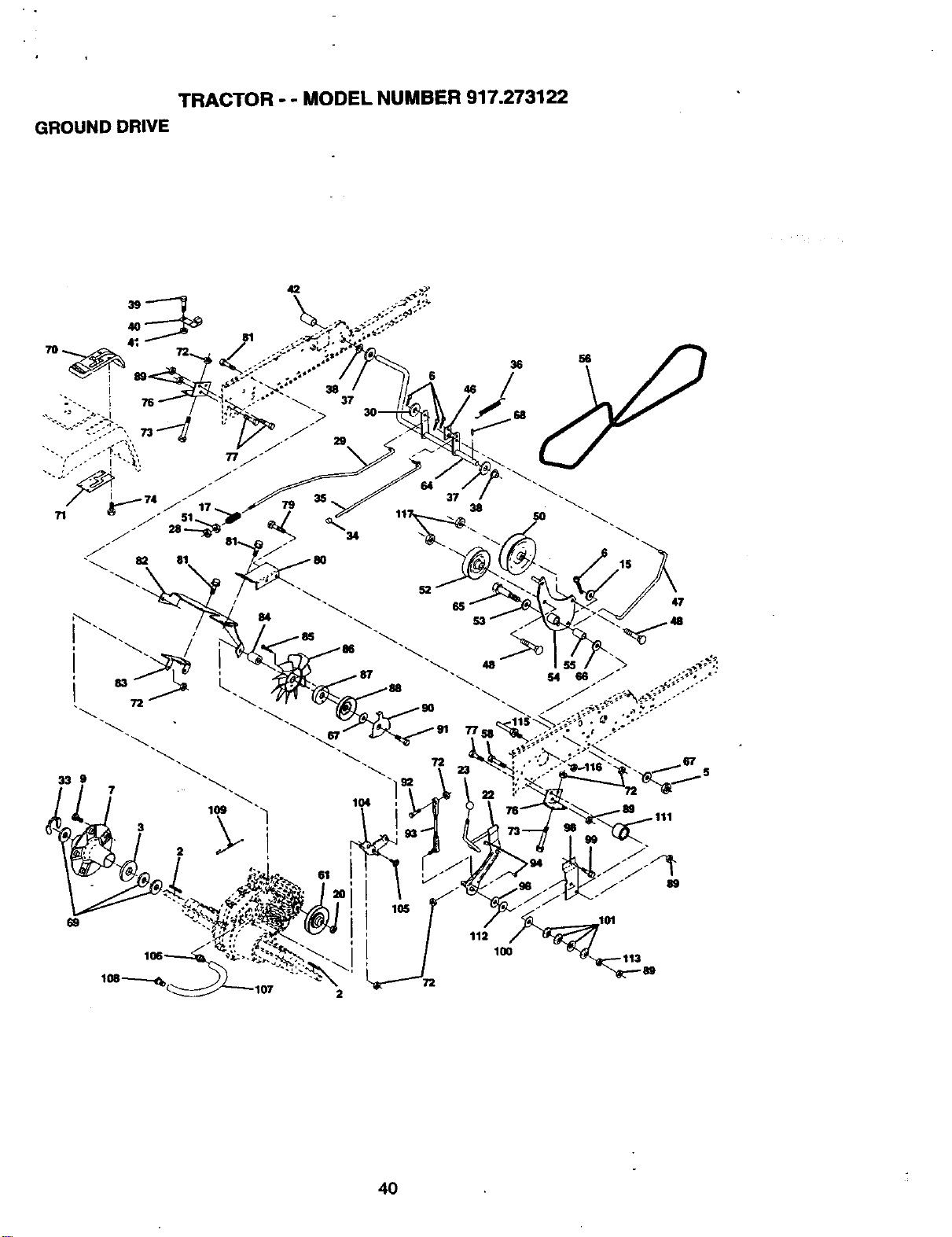
TRACTOR - - MODEL NUMBER 917.273122
GROUND DRIVE
33 9
35
61
105
i
2
38
112
100
89
4O
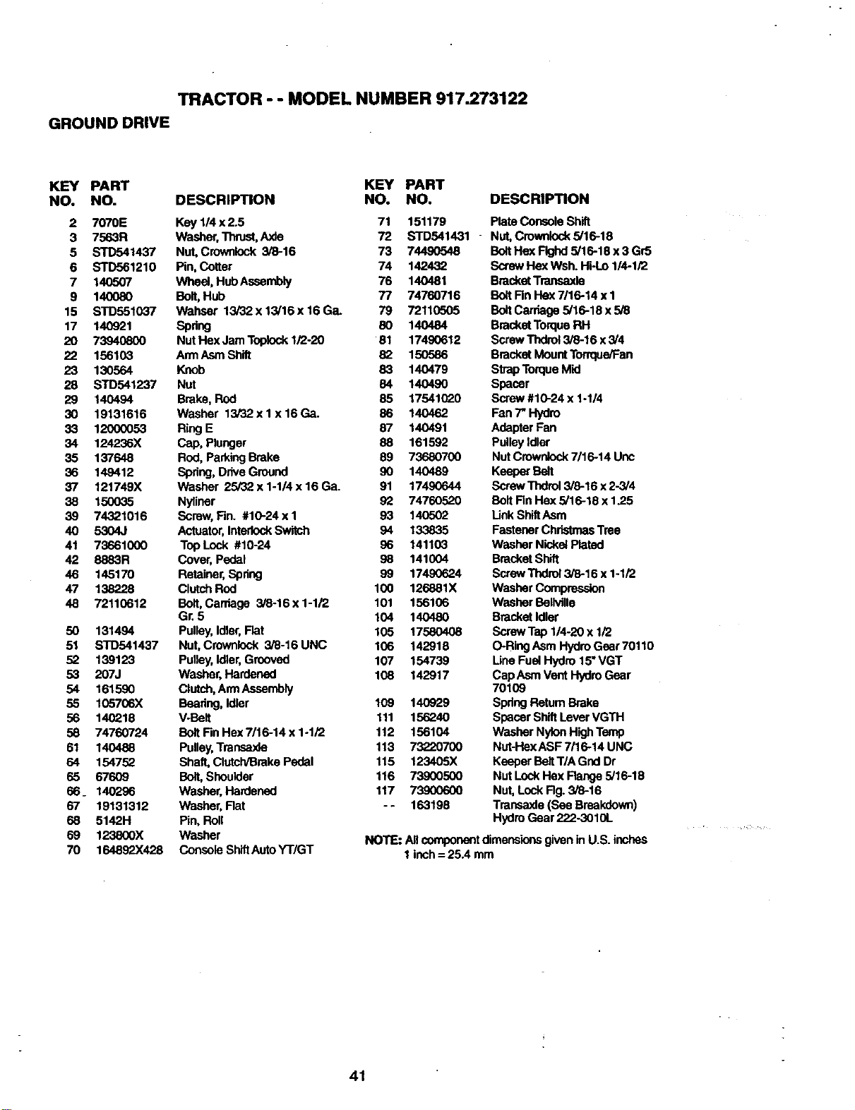
TRACTOR - - MODEL NUMBER 917.273122
GROUND DRIVE
KEY PART KEY PART
NO. NO. DESCRIPTION NO. NO.
2 7070E Key 1/4 x 2.5 71 151179
3 7563R Washer,Thrust,A,_de 72 STD541431
5 STD541437 Nut, Crownlock 3/8-16 73 74490548
6 STD561210 Pin, Cotter 74 142432
7 140507 Wheel, HubAssembly 76 140481
9 140080 Bolt,Hub 77 74760716
15 STD551037 Wahser 13i32x13/16x16Ga. 79 72110505
17 140921 Spdng 8O 140484
20 73940800 Nut Hex JamTopleck 1/2-20 81 17490612
22 156103 Ann Asm Shift 82 150586
23 130564 Knob 83 140479
28 STD541237 Nut 84 140490
29 140494 Brake, Rod 85 17541(_0
30 19131616 Washer 13/32xlx16Ga. 86 140462
33 12000053 Ring E 87 140491
34 124236X Cap, Plunger 88 161592
35 137648 Rod, ParkingBrake 89 73680700
36 149412 Spdng, DriveGround 90 140489
37 121749X washer 25/32 x 1-1/4 x 16 Ga. 91 17490644
38 150035 Nyliner 92 74760520
39 74321016 Screw,Fin. #10-24 x I 93 140502
40 5304J Actuator,InterlockSwitch 94 133835
41 73661000 TopLock #10-24 96 141103
42 8883R Cover, Pedal 98 141004
46 145170 Retainer,Spdng 99 17490624
47 138228 ClutchRod 100 126881X
48 72110612 Bolt, Cardage 3/6-16 x 1-1/2 101 156106
Gr.5 104 140480
50 131494 Pulley,Idler,Flat 105 17580408
51 STD541437 Nut, Crownlock 3/8-16 UNC 106 142918
52 139123 Pulley,Idler,Grooved 107 154739
53 207J Washer, Hardened 108 142917
54 161590 Clutch, An'nAssembly
55 105706X Beadng, Idler 109 140929
56 140218 V-Belt 111 156240
58 74760724 Bolt Fin Hex7/16-14 x 1-1/2 112 156104
61 140488 Pulley,Transaxle 113 73220700
64 154752 Shaft, Clutch/BrakePedal 115 123405X
65 67609 Bolt,Shoulder 116 73900500
66_ 140296 washer, Hardened 117 73900600
67 19131312 washer, Rat -- 163198
68 5142H Pin, Roll
69 123800X Washer
70 164892X428 Console ShiftAutoYTiGT
DESCRIPTION
PlataConsole Shift
Nut,Crownlock5/16-18
BoltHex Flghd5/16-18 x 3 Gr5
ScrewHex Wsh. WHo 114-1/2
BracketTmnsaxle
Bo_tRn Hex7/16-14 x1
BoltCarriage 5/16-18 x 5/8
BracketTorqueRH
ScrewThdrol3/8-16 x 3/4
Bracket MountTerrque/Fan
StrapTorqueMid
Spacer
Screw #10-24 x 1-114
Fan 7" Hydro
Adapter Pan
PulleyIdler
Nut Crownlock7116-14Unc
Keeper Belt
Screw Tndrol3/8-16 x 2-3/4
Bolt Rn Hex 5/16-18 x 1.25
Unk ShiftAsm
Fastener ChristmasTree
washer NickelPlated
BracketShift
ScrewThdrol3/8-16 x 1-1/2
Washer Compression
Washer Bollville
Bracket Idler
ScrewTap 1/4-20 x 1/2
O-RingAsm HydroGear 70110
Une Fuel Hydro 15"VGT
Cap AsmVent Hydro Gasr
7O1O9
Spdng Retum Brake
Spacer ShiftLever VGTH
Washer NylonHighTemp
Nut-HexASF 7116-14UNC
Keeper BeltT/A Gnd Dr
Nut LockHex Range 5/16-18
Nut,LockRg. 3/8-16
Tmnsaxle (See Breakdown)
HydroGear 222-3010L
NOTE: All componentdimensionsgwenin U.S. inches
1inch= 25.4 mm
41
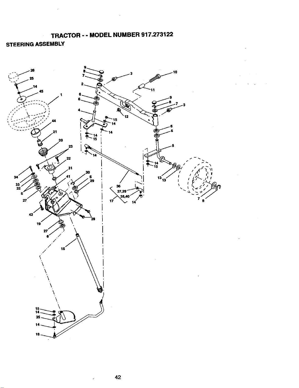
TRACTOR - - MODEL NUMBER 917.273122
STEERING ASSEMBLY
42
19
28
42
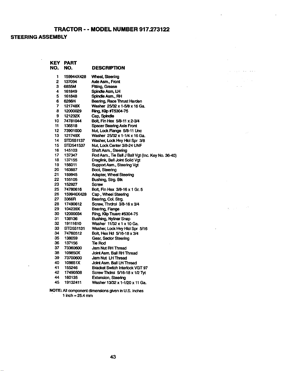
TRACTOR - - MODEL NUMBER 917.273122
STEERING ASSEMBLY
KEY PART
NO. NO. DESCRIPTION
1 159944X428
2 137094
3 6855M
4 161849
5 161848
6 6266H
7 121748X
8 12OOO029
9 121232X
10 74781044
11 136518
12 73901000
13 121749X
14 STD551137
15 STD541537
16 145103
17 137347
18 137155
19 156011
20 163887
21 159945
22 155105
23 152927
25 74780616
26 159946X428
27 3366R
28 17490612
29 104239X
30 12000034
31 138136
32 19111610
33 STD551131
34 74760512
35 138059
36 137156
37 73360600
38 109850X
39 73700600
40 109851X
41 155246
42 17490508
44 160135
45 19132411
Wheel,Steering
A,xleAsm.,Front
Fitting,Grease
Spino_ Asm,LH
S_nd_Asm.,RH
Bearing,Race ThrustHarden
Washer 25/32 x 1-5/8 x 16 Ga.
Ring, I_p #T5304-75
Cap,Sp_d_
Bolt,Fin Hex 5/8-11 x2-3/4
Spacer BeadngAxleFront
Nut,LockFlange 5/8-11 Unc
Washer 25/32 x 1-1/4 x 16 Ga.
Washer, LockHvy Hid Spr 3/8
Nut,LockCenter 3/824 UNF
ShaftAsm.,Steedng
RodAsm.,TieBallJ BallVgt(Inc. KeyNo. 36-40)
Draglink,Bail JointSolidVgt
SupportAsm., SteedngVgt
Boot,Steering
Adapter,Wheel Steedng
Bushing,Strg.BIk
Screw
Bolt,Rn Hex 3/8-16 x I Gr.5
Cap, Wheel Steedng
Bearing,Col. Strg.
Screw,Thrdret 3/6-16 x 3/4
Bear_j, Range
Ring, KlipTruarc#5,..'.'.'.'.'.'.'.'_4-75
Bushing,NylinerSnap
Washer 11/32 x lx 10 Ga.
Washer,LockHvyHlclSpr 5/16
Bolt,FlexHd 5/16-18 x 3/4
Gear, SectorSteedng
T_eRod
Jam NutRH Thread
JointAsm.Ball RH Thread
Jam Nut LHThread
JointAsm.Ball LHThread
Bracket SwitchInterlockVGT 97
Sinew "rhdret5/16-18 x 1/2 Tyt
Extension,Steering
Washer 13/32 x 1-1/20 x 11Ga.
NOTE: AllcomponentdimensionsgiveninU.S. inches
1inch= 25A mm
43
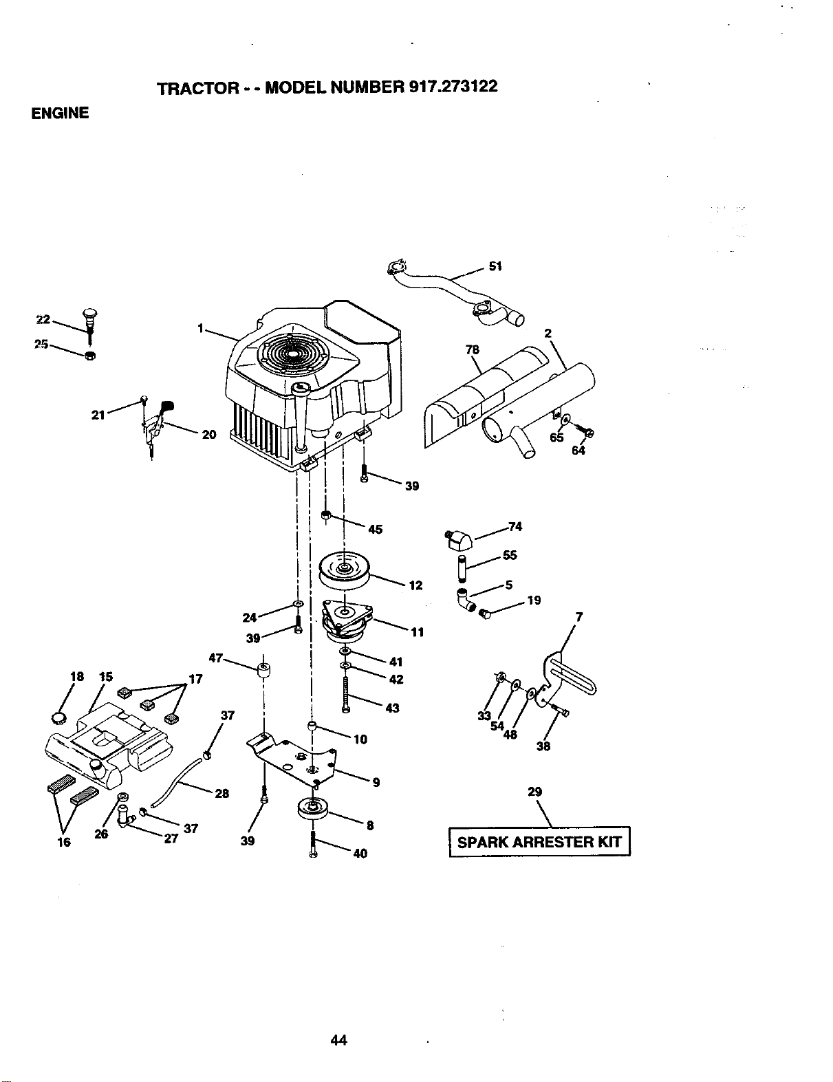
ENGINE
TRACTOR - - MODEL NUMBER 917.273122
18 15
2O
2
16
27
39
\
I SPARK ARRESTER KIT I
44
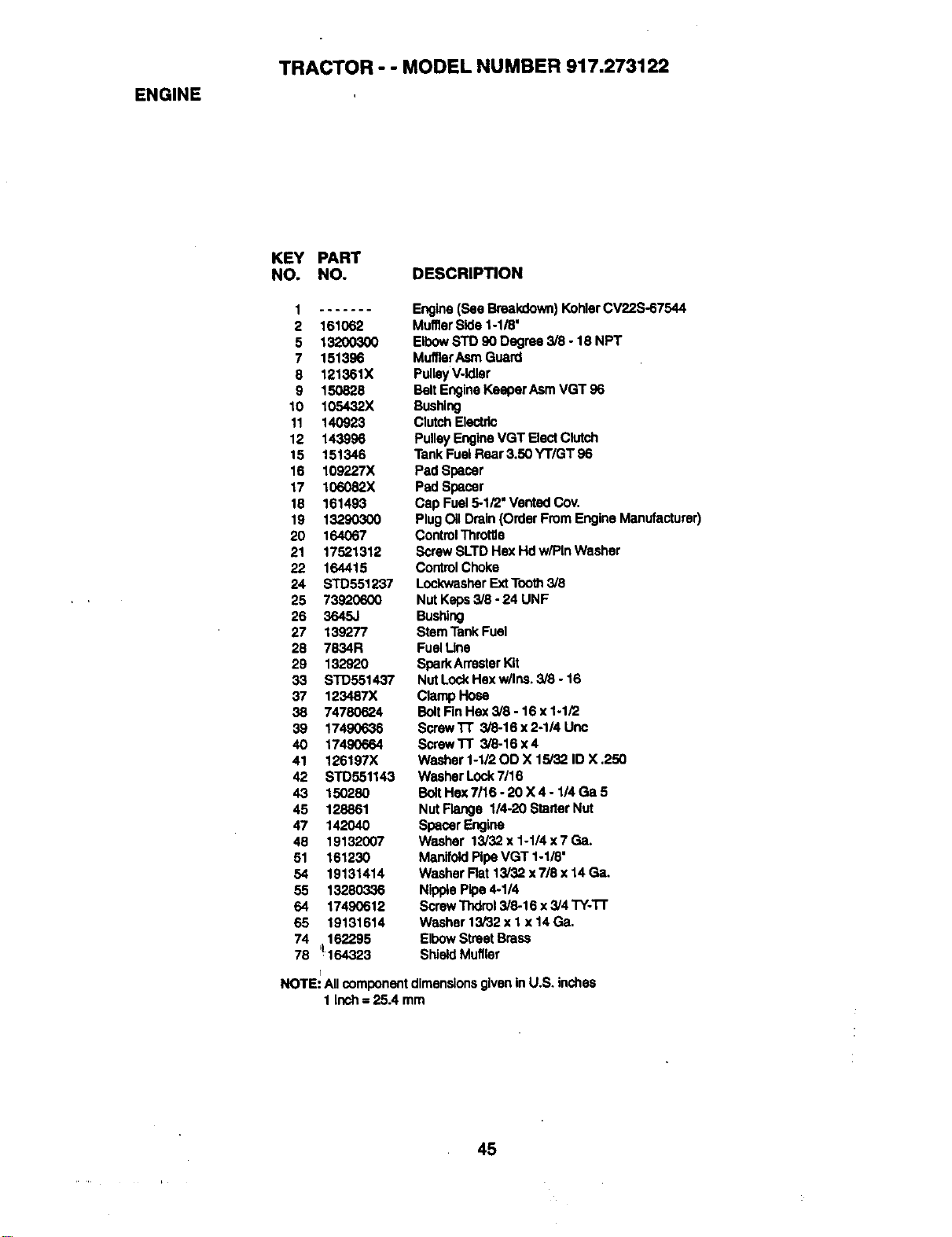
ENGINE
TRACTOR - - MODEL NUMBER 917.273122
KEY PART
NO. NO. DESCRIPTION
2 161062
5 13200300
7 151396
8 121361X
9 150828
10 105432X
11 140923
12 143996
15 151346
16 109227X
17 106082X
18 161493
19 13290300
20 164067
21 17521312
22 164415
24 STD551237
25 73320600
26 3645J
27 139277
28 7834R
29 132920
33 STD551437
37 123487X
38 74780624
39 17490636
40 17490664
41 126197X
42 STD551143
43 150280
45 128861
47 142040
48 19132007
51 161230
54 19131414
55 13280336
64 17490612
65 19131614
74 _162295
78 !164323
I
Engine(See Breakdown) KohlerCV22S-67544
MufflerSide 1-1/8'
ElbowSTO 90 Degree 3/8 - 18 NPT
MufflerAsrnGuard
PulleyV-Idler
BeltEngineKeaper AsmVGT 96
Bushing
ClutchElectric
PulleyEngineVGT Elect Clutch
TankFuel Rear 3.50 YT/GT 96
Pad Spacer
Pad Spacer
Cap Fuel 5-1/2" Vented Cov,
PlugOil Drain (Order From Engine Manufacturer)
ControlThrottle
ScrewSLTD Hex Hd w/Pin Washer
ControlChoke
LockwasherExtTooth3/8
Nut Keps3/8 - 24 UNF
Bushing
Stem TankFuel
FuelLine
SparkArrasterKit
Nut LockHexw/Ins. 3/8 - 16
ClampHose
BoltFinHex 3/8 - 16 x 1-1/2
ScrewTT 3/8-16 x 2-1/4 Unc
ScrewTT 3/8-16 x4
Washer 1-1/20D X 15/32 ID X ,250
Washer Lock7/16
BoltHex 7116- 20 X 4 - 1/4 Ga 5
Nut Flange 1/4-20 Starter Nut
SpacerEngine
Washer 13/32 x 1-1/4 x 7 Ga.
ManifoldPipeVGT 1-1/8"
Washer Rat 13/32 x 7/8 x 14 Ga.
NipplePipe 4-1/4
ScrewThdrol3/8-16 x 3/4 TY-'1-r
Washer 13/32 x I x 14 Ga,
ElbowStreet Brass
ShieldMuffler
NOTE: All componentdimensionsgivenin U.S. inches
1 inch = 25A mm
45
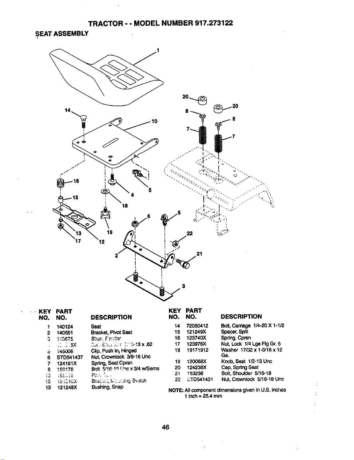
TRACTOR - - MODEL NUMBER 917.273122
SEATASSEMBLY
12
5
21
KEY PART
NO. NO.
1 140124
2 140551
3 I,:C_375
J
o i4_06
6 STD541437
7 124151X
B I_0175
13 121248X
DESCRIPTION
Seat
Bracket,Pivot Seat
Str_; F_r:dot
2.oi &h,._";L.:r 2; i_3-I_ x .62
Clip, Push In_Hinged
Nut,Crownlock 318-16Unc
Spring,Seat Cprsn
Bolt _! _-! q L'_ x3/4 w/Sems
P?.:,,]_ ,
Bushing,Snap
KEY PART
NO. NO. DESCRIPTION
14 72050412 Bolt, Carriage 1/4-20 X 1-1/2
15 121249X Spacer,Spilt
16 123740X Spring,Cprsn
17 123976X Nut, Lock 1/4 Lge Fig Gr. 5
18 19171912 Washer 17i32x1-3/16x12
Ga,
19 120068X Knob,Seat 1/2-13 Unc
20 124235X Cap, SpringSeat
21 153236 Bolt,Shoulder 5/16-18
22 L:TD541431 Nut, Crownlock 5/15-18 Unc
NOTE: Allcomponentdimensionsgivenin U.S. inches
1 inch= 25.4 mm
46
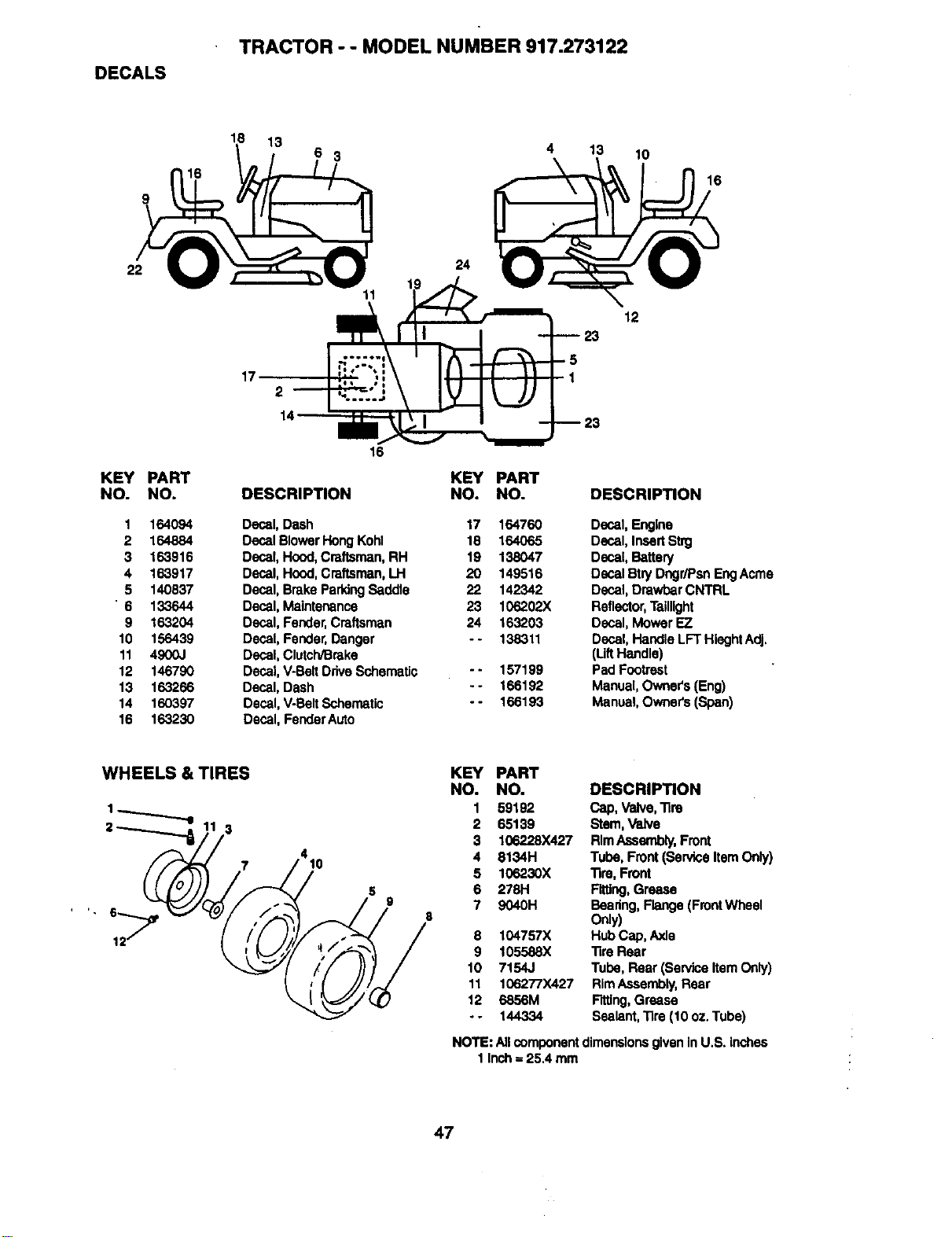
DECALS
TRACTOR - - MODEL NUMBER 917.273122
18
13
3
4 13
10
16
22
KEY PART
NO. NO.
1 164094
2 164884
3 163916
4 163917
5 140537
'6 133644
9 163204
10 156439
11 4900J
12 146790
13 163266
14 160397
16 163230
11
17
2
I
16
DESCRIPTION
Decal, Dash
Decal BlowerHong Kohl
Decal,Hood,Craftsman, RH
Decal, Hood,Craftsman,I.J-I
Decal, Brake ParkingSaddle
Decal, Maintenance
Decal, Fender,Craftsman
Decal, Fender,Danger
Decal, Clutch/Brake
Decal, V-BeltDrive Schematic
Decal, Dash
Decal, V-BeltSchematic
Decal, FenderAuto
24
KEY
NO.
17
18
19
2O
22
23
24
°.
°=
°°
23
1
12
PART
NO. DESCRIPTION
164760 Decal, Engine
164065 Decal, InsertStn3
138047 Decal, Battery
149516 Decal Stry Dngr/PsnEng Acme
142342 Decal,Drawbar CNTRL
106202X Reflector,Taillight
163203 Decal, Mower EZ
138311 Decal, HandleLIT HlaghtAdj,
(LiftHandle)
157199 Pad Footrest
166192 Manual, Owner's(Eng)
166193 Manual, Owners (Span)
WHEELS & TIRES
1._........_
KEY PART
NO. NO. DESCRIPTION
1 59192 Cap, Valve, Tire
2 65139 Stem,Valve
3 106228X427 RimAssembly,Front
4 8134H Tube, Front (san/ice Item Only)
5 106230X Tire, Front
6 278H Fitting,Grease
7 9040H Bearing, Flange (FrontWheel
Only)
8 104757X Hub Cap,Axle
9 105588X Tire Rear
10 7154J Tube, Rear (sa_viceItem Only)
11 106277X427 RimAssembly,Rear
12 6856M Fitting,Grease
- - 144334 Sealant,Tire (10 oz, Tube)
NOTE: Allcomponentdimensionsgiven inU.S. Inches
1 Inch= 25,4 mm
47
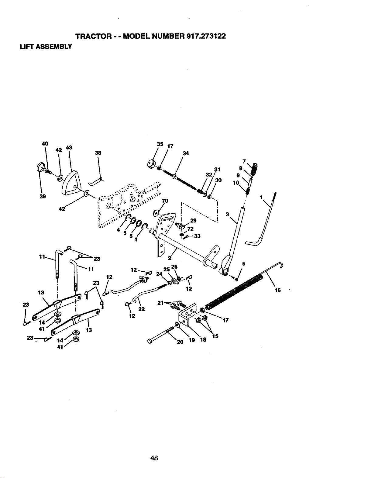
TRACTOR - - MODEL NUMBER 917.273122
LIFTASSEMBLY
4O
39
43
42
38
15
16
48
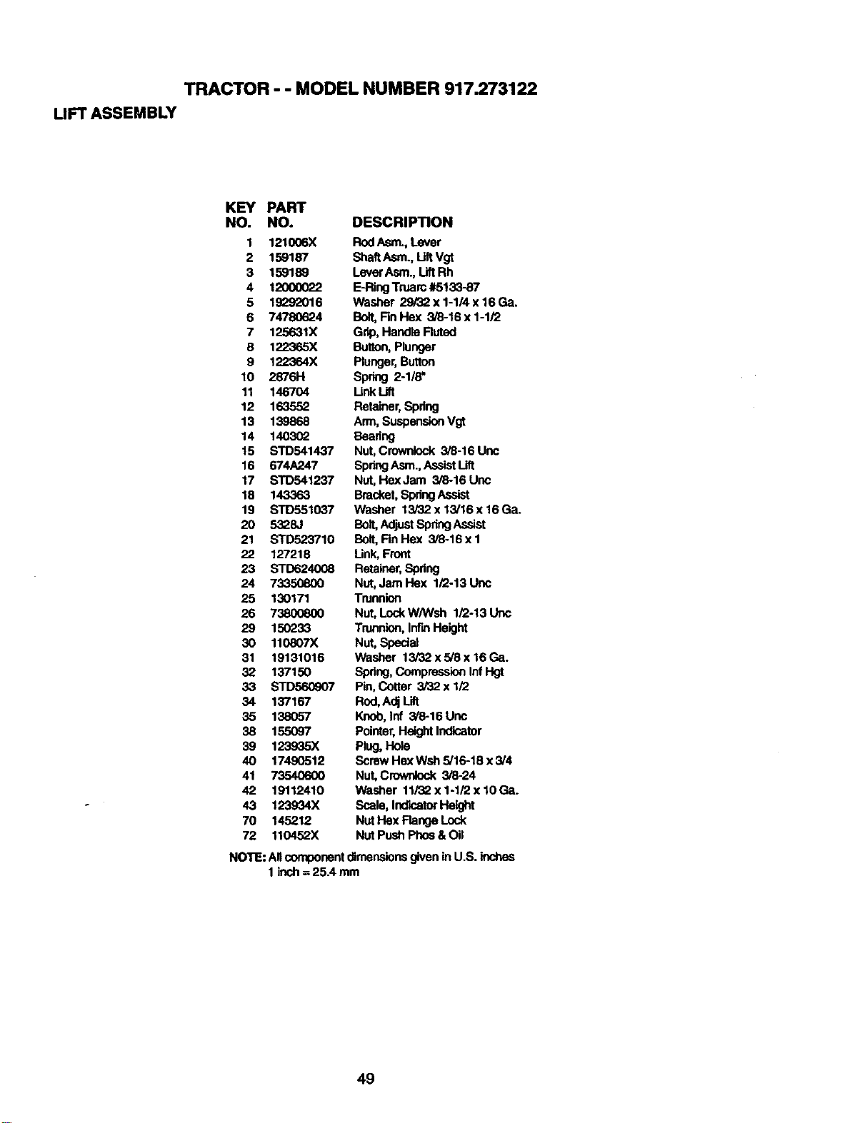
TRACTOR - - MODEL NUMBER 917.273122
UFT ASSEMBLY
KEY PART
NO. NO. DESCRIPTION
1 121006X Rod Asm., Lever
2 159187 ShaftAsm., LiftVgt
3 159189 LeverAsm., LiftRh
4 12000022 E-RingTruarc #5133-87
5 lgL_2016 Washer 29/32 x 1-1/4 x 16 Ga.
6 74780624 Bolt,FinHex 3/8-16 x 1-1/2
7 125631X Grip,Handle Fluted
8 122365X Button,Plunger
9 122364X Plunger,Button
10 2876H Spring 2-1/8"
11 146704 LinkLift
12 163552 Retainer,Spring
13 139868 Arm, SuspensionVgt
14 140302 Beadng
15 STD541437 Nut,Crownlock 3/8-16 Unc
16 674A247 SpringAsm.,AssistUft
17 STD541237 Nut,HexJam 3/8-16 Unc
18 143363 Bracket,SpringAssist
19 STD551037 Washer 13i32x13/16x16Ga.
20 5328J Bolt,AdjustSpdngAssist
21 STD523710 Bolt,FinHex 3/8-16xl
22 127218 Link,Front
23 STD624008 Retainer,Spdng
24 73350800 Nut,Jam Hax 1/2-13 Uric
25 130171 Trunnion
26 73800800 Nut,LockW/Wsh 1/2-13Unc
29 150233 Trunnion,InfLnHeight
30 110807X Nut, Special
31 19131016 Washer 13/32x5/8x16Ga.
32 137150 Spdng,Compressioninf Hgt
33 STD560907 Pin,Cotter 3/32 x 1/2
34 137167 Rod,Adj Lift
35 138057 Knob,Inf 3/8-16 Unc
38 155097 Pointer,HeightIndicator
39 123935X Plug, Hole
40 17490512 Screw HexWsh 5/16-18 x3/4
41 73540600 Nut,Crownlock 3/8-24
42 19112410 Washer 11/32 x 1-1/2 x 10 Ca.
43 123934X Scale, IndicatorHeight
70 145212 NutHax FlangeLock
72 110452X Nut Push Phos &Oil
NOTE: All componentdimensionsgiven inU.S. inches
1 inch= 25.4 mm
49
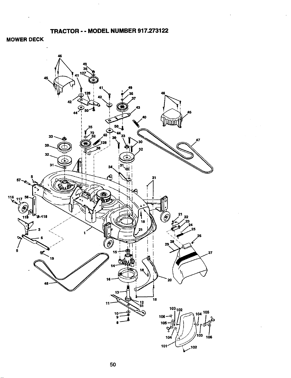
TRACTOR - - MODEL NUMBER 917.273122
MOWER DECK
46
49
45
\
I
43
21
46
47
22
26
5O
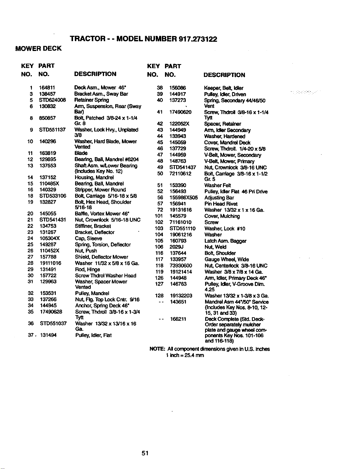
TRACTOR - - MODEL NUMBER 917.273122
MOWER DECK
KEY PART KEY PART
NO. NO. DESCRIPTION NO. NO. DESCRIPTION
1 164811 DeckAsm., Mower 46" 38 156086 Keeper,Belt, Idler
3 138457 BracketAsm., Sway Bar 39 144917 Pulley,Idler,Driven
5 S'10624008 Retainer Spring 40 137273 Spring,Secondary44/46/50
6 130832 Arm, Suspension,Rear (Sway . Vent
Bar) 41 17490620 Screw,'lTldrefl3/8-16 x 1-1/4
8 850857 Bolt, Patched 3/8-24 x 1-1/4 Tyrt
Gr. 8 42 122052X Spacer,Retainer
9 STD551137 Washer, LockHv,/., Unplatad 43 144949 Arm, IdlerSecondary
3/8 44 133943 Washer,Hardened
10 140296 Washer, Hard Blade, Mower 45 145059 Cover,Mandrel Deck
Vented 46 137729 Screw,Thdroll. 1/4-20x5/8
11 163819 Blade 47 144959 V-Bait, Mower, Secondary
12 129895 Bearing,Ball, Mandrel #6204 48 148763 V-Belt,Mower, Primary
13 1375,53 SheftAsm. w/Lower Beadng 49 STD541437 Nut, Crownlock3/8-16 UNC
(includesKey No. 12) 50 72110612 Bolt,Cawlage 3/8-16 x 1-1/2
14 137152 Housing,Mandrel Gr.5
15 110485X Bearing,Ball, Mandrel 51 1533,90 Washer Felt
16 140329 Stripper,Mower Round 52 156493 Puney,IdlerFlat 46 Pri Drive
18 STD533106 Bolt,Cardage 5/16-18 x5/8 56 155986X505 AdjustingBar
19 132827 Bolt,Hex Head, Shoulder 57 156941 PinHead Rivet
5/16-18 72 19131616 Washer 13/32x 1 x 16 Ca.
20 145055 Baffle, VortexMower 46" 101 145579 Cover, Mulching
21 STD541431 Nut,Crownlock 5/16-18 UNC 102 71161010 Screw
22 134753 SlJffiner,Bracket 103 STD551110 Washer, Lock #10
23 131267 Bracket,Deflector 104 19061216 Washer
24 105304X Cap, Sleeve 105 160793 LatchAsm.Bagger
25 149287 Spdng,Torsion,Deflector 106 2029J Nut,Weld
26 110452X Nut,Push 116 137644 Bolt,Shoulder
27 157788 Shield, DeflectorMower 117 133957 Gauge Wheel, Wide
28 19111016 Washer 11/32 x5/8 x 16 Ga. 118 73930600 Nut,Centedock 3/8-16 UNC
29 131491 Rod, Hinge 119 19121414 Washer 3/8x7/Sx14Ga.
30 157722 ScrawThdrolWasherHead 126 144948 Arm, ldler,PdmaryDeck 46"
31 129963 Washer, Spacer Mower 127 146763 Pulley, Idler,V-Groove Dim.
Vented 4.25
32 153531 Pulley,Mandrel 128 19132203 Washer13/32x1-3/8x3Ga.
33 137266 Nut, Fig.Tap LockCntr. 9/16
- - 143651 Mandret Asm44"/50"Service
34 144945 Anchor,Spring Deck 46" (IncludesKey Nos.8-10, 12-
35 17490628 Screw, Thdroll 3/6-16 x 1-3/4 15, 31 and33)
Tytt - - 166211 Deck Completa (Std.Deck-
36 STD551037 Washer 13i32x13/16x16 Ordersaparatelymulcher
Ga. plataand gauge whnelcom-
37 - 131494 Pulley, Idler,Flat ponentsKey Nce. 101-106
and 116-118)
NOTE: All componentdimensionsgivenin U.S. inches
1 inch= 25A mm
51
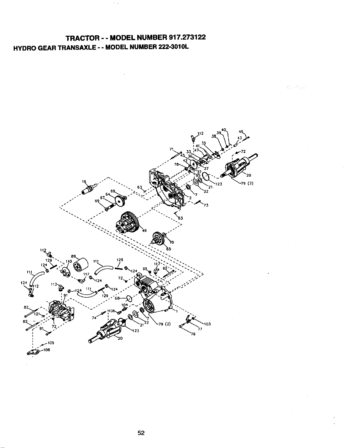
TRACTOR - - MODEL NUMBER 917.273122
HYDRO GEAR TRANSAXLE -- MODEL NUMBER 222-3010L
7
2
(2)
52
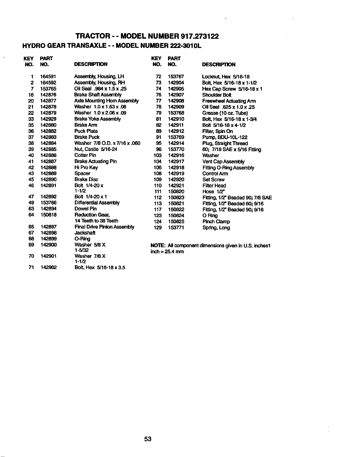
TRACTOR - - MODEL NUMBER 917.273122
HYDROGEARTRANSAXLE- - MODELNUMBER222-3010L
KEY PART KEY PART
NO. NO. DESCRIPTION NO. NO. DESCRIPTION
1 164591 Assembly,Housing,LH 72 153767
2 164592 Assembly,Housing,RH 73 142904
7 153765 ORSeal .984 x1.5 x .25 74 142905
16 142876 Brake ShaftAssembly 76 142907
20 142877 Axle MountingHornAssembly 77 142908
21 142878 Washer 1.0 x1.63 x .08 78 142909
22 142879 Washer 1.Ox2.06x.09 79 153768
33 142929 BrakeYokeAssembly 81 142910
35 142880 BrakeArrn 82 142911
36 142882 Puck Plate 89 142912
37 142883 Brake Puck 91 153769
38 142884 Washer 7/80.D. x7/16 x .060 95 142914
39 142885 Nut,Castle 5/16-24 96 153770
40 142886 Cotter Pin 103 142916
41 142887 BrakeActuating Pin 104 142917
42 142888 Hi Pro Key 106 142918
43 142889 Spacer 108 142919
45 142890 Brake Disc 109 142920
46 142891 Bolt 114-20x 110 142921
1-1/2 111 150820
47 142892 Bolt 1/4-20xl 112 150823
49 153766 DiflerentialAssembly 113 150821
63 142894 Dowel Pin 117 150822
64 150818 Reductla_lGear, 123 150824
14 Teethto38 Teeth 124 150825
65 142897 Final DdvePinionAssembly 129 153771
67 142898 Jackshaft
68 142899 O-Ring
69 142900 Washer 5/8 X
1-5/32
70 142901 Washer 7/8 X
1-1/2
71 142902 Bolt,Hex 5/16-18x3.5
Locknut,Hex 5/16-i6
Bolt, He)( 5/16-18 x 1-1/2
HexCap Screw 5/16-18x 1
ShoulderBolt
FreewheelActuatingArm
OII Ssel .625 x 1.0 x ,25
Grease (10 oz. Tube)
Bolt,Hex 5/16-18 x 1-3/4
Bolt 5/16-18 x 4-1/2
Filter,SpinOn
Pump, BDU-10L-122
Plug,StraightThread
60i 7/18 SAE x 5/16 F'_,ing
Washer
Vent CapAssembly
Fiffing O-RingAssembly
ControlArm
Set Screw
FilterHead
Hose 1/2"
Fitting,1/2"Beaded 90i 7/8 SAE
Fitting,1/2"Beaded 60i 9/16
Fitting,1/2"Beaded 9019/16
O Ring
PinchClamp
Spdng,Long
NOTE: Allcomponentdimensionsgiven in U.S. inches1
inch= 25.4 mm
53
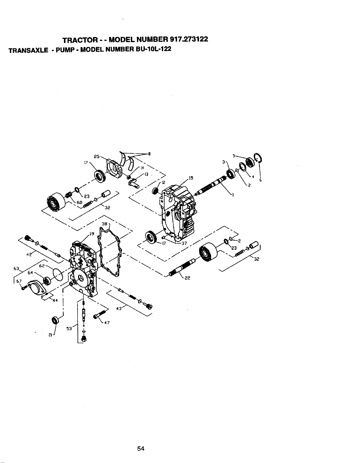
TRACTOR - - MODEL NUMBER 917.273122
TRANSAXLE- PUMP - MODEL NUMBER BU-10L-122
i
54

TRACTOR - - MODEL NUMBER 917.273122
TRANSAXLE - PUMP - MODEL NUMBER BU-10L-122
KEY PART
NO. NO. DESCRIPTION
1 144569 Shaft, Pump
2 122716X Ring, Retaining
3 122745X Bearing, Ball
4 122715X Spacer
5 122700X Sea, Lip
6 122699X Ring,Retaining
8 122767X Beadflg,Cradle
12 122717X Seal, lip
13 122748X Arm, Trunnion
14 122749X Guide, Slot
15 144571 HousingWit,Transmission
17 122770X Beadng,Thrust, Ball
19 1,53801 Center SeclJonKit
21 122722X Seal, Lip
22 144573 Shaft, Motor
23 142978 Washer, BlockThrust
25 127148X Swashplate,Variable
32 142938 BlockAssembly
37 122786X Pin,Stainless,Headless
38 122718X Gasket, Center Section
42 144578 Check Valve Kit
43 144578 Check Valve Kit
44 144579 Charge Relief Kit
47 122752X Screw,Socket Head, Cap
53 127153X BypassValve Kit
60 142977 BlockSpdng
62 144581 O-Ring
63 144582 ChargePump Kit
64 144583 GerotorAssembly
67 144584 Screw,Socket Head, Cap
-- 153769 PumpAssembly,Complete
55
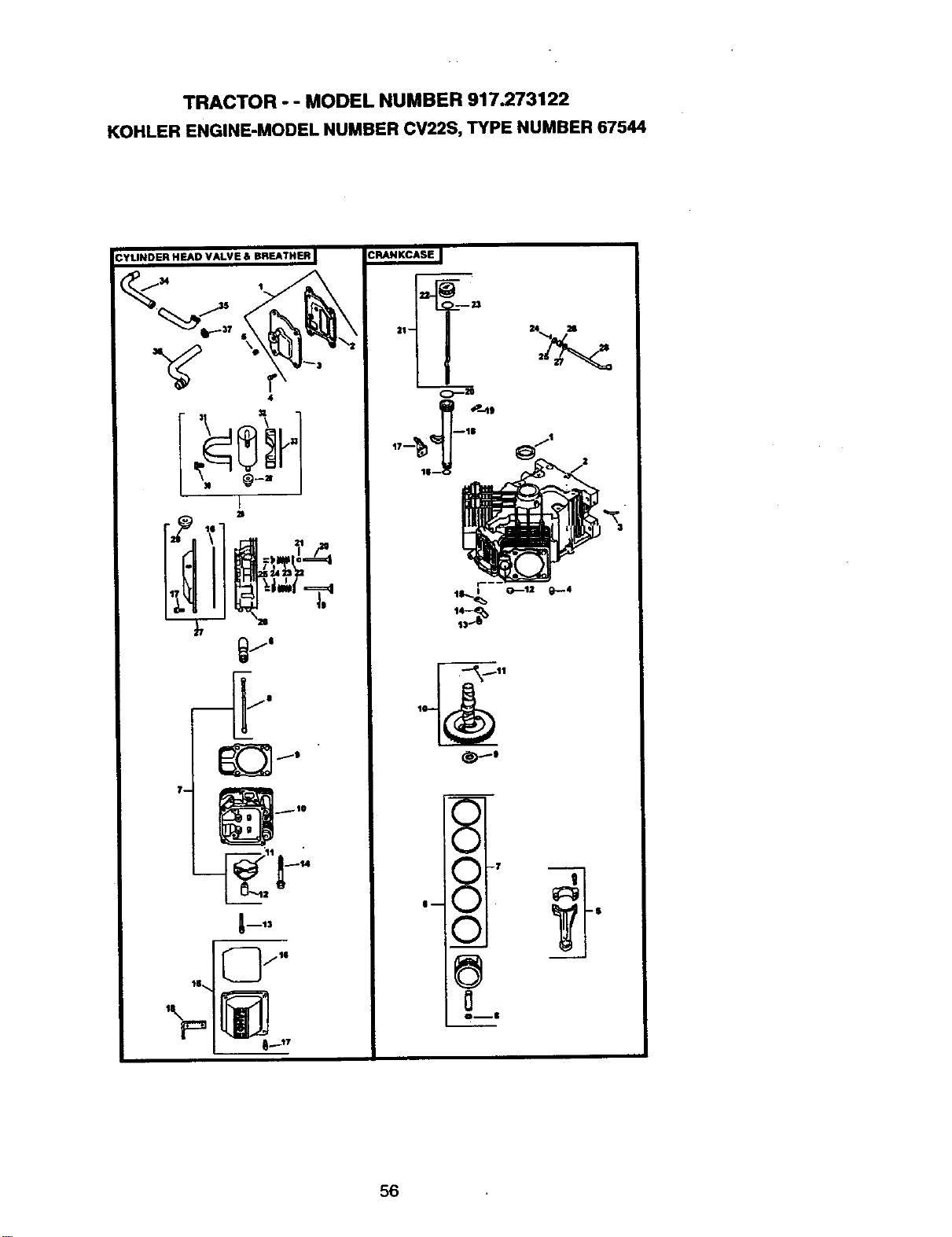
TRACTOR - - MODEL NUMBER 917.273122
KOHLER ENGINE-MODEL NUMBER CV22S, TYPE NUMBER 67544
S'_ I 7
|--
V I
0
Oml
56
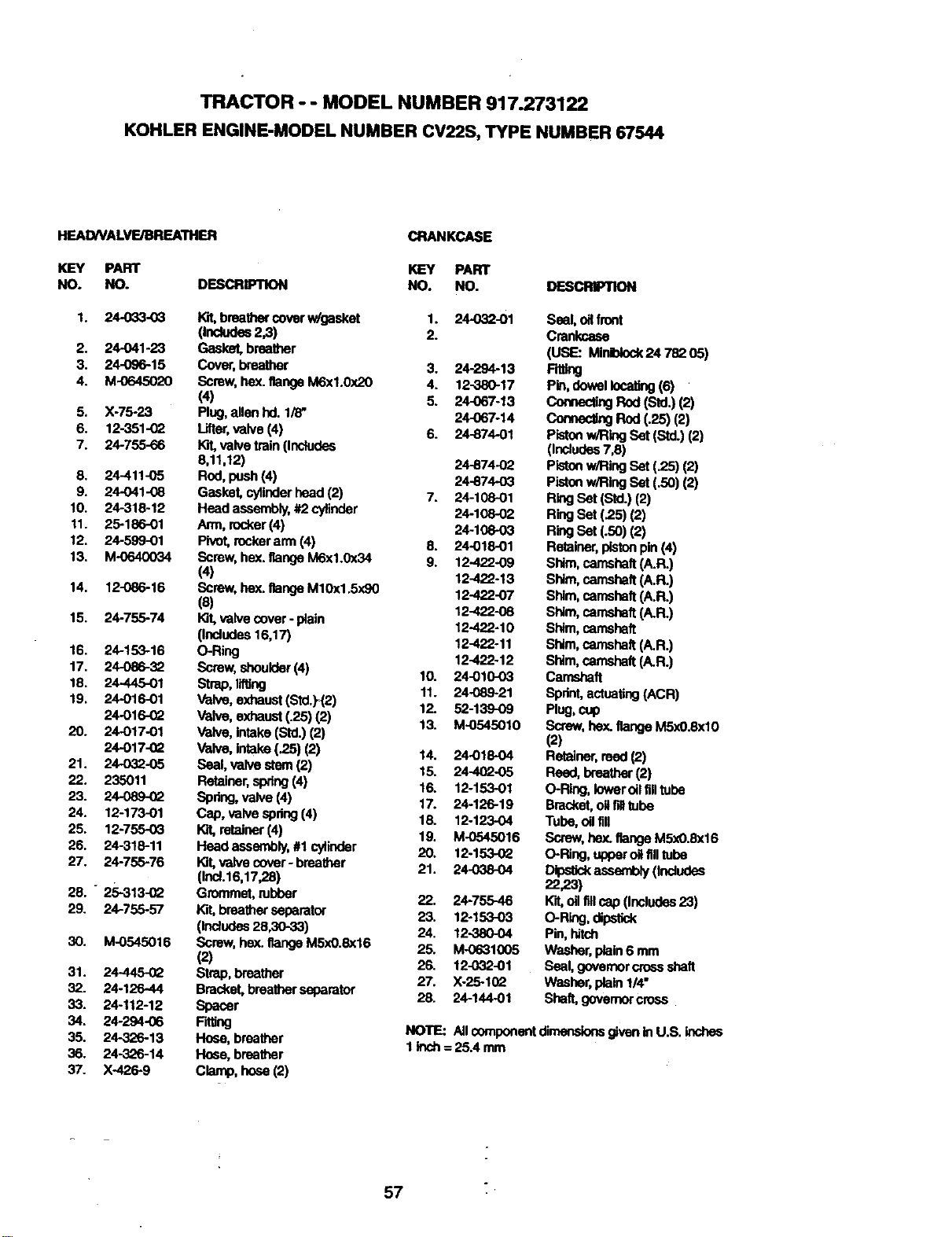
TRACTOR - - MODEL NUMBER 917.273122
KOHLER ENGINE-MODEL NUMBER CV22S, TYPE NUMBER 67544
HEADNALVE/BREATHER
KEY PART
NO. NO. DESCRIP11ON
1. 24-033-03
2. 24-041-23
3. 24-096-15
4. M-0645020
5. X-75-23
6. 12-351-02
7. 24-755-66
8. 24-411-05
9. 24-041-08
10. 24-318-12
11. 25-186-01
12. 24-599-01
13. M-0640034
14. 12-086-16
15. 24-755-74
16. 24-153-16
17. 24-086-32
18. 24.445-O1
19. 24-016-O1
24-016-(_
20. 24-017-01
24.-017-0Q
21. 24032-05
22. 235011
23. 24-089-02
24. 12-173-01
25. 12-755-0_
26. 24-318-11
27. 24-755-76
28. - 25-313-02
29. 24-755-57
30. M-8545016
31. 24445-02
32. 24-126-44
33. 24-112-12
34. 24-294-06
35. 24-326-13
36. 24-326-14
37. X-426-9
breathercover w/gasket
(Includes2,3)
Gasket, breather
Cover,breather
Screw, hax. flangeM6xl.0x20
(4)
Plug,allen hd. 1/8"
lifter, valve (4)
K'd,valve train (Includes
8,11,12)
Rod,push(4)
Gasket, cylinderhead (2)
Head assembly,#2 cylinder
Aim, rocker(4)
Pivot,rockerarm (4)
Screw, hex.flangeM6x1.0x34
(4)
Screw, hex. flangeM10x1.5x90
(8)
Kit,valve cover - plain
(Includes 16,17)
O-Ring
Screw, shoulder(4)
Strap,lifting
Valve, exhaust(std.)_(2)
Valve,exhaust(.25)(2)
Valve, intake(Std.)(2)
Valve, intake (.25) (2)
Seal, valve stem (2)
Retainer,spring(4)
Spring,valve (4)
Cap, valve spdug(4)
Kit,retainer(4)
Head asserchly,#1 cylinder
Kit,valve cover- breather
(Inoi.16,17,28)
Grommet, rubber
breather aspsmter
(Includes28,30-33)
Screw, he)(.flangeM5xO.8x16
(2)
Strap, breather
Bracket,breatherseparator
spacer
Rfting
Hose, breather
Hose, breather
C_enp, h_e (2)
CRANKCASE
KEY PART
NO. NO. DES_
1.
2.
3,
4.
5.
6.
7.
8,
9.
10.
11.
12.
13.
14.
15.
16.
17.
18.
19.
20.
21.
22,
23.
24,
25.
26.
27.
28.
24-032-01 Seal, oll front
Crankcase
(USE: Miniblock24 782 05)
24-294-13 Fitting
12-380-17 Pin,dowel locating(6)
24-067-13 ConnectingRod (Std.) (2)
24-067-14 ConnectingRod (.25) (2)
24-874-01 Pistonw/Ring Set (Std.)(2)
(Includes7,8)
24-874-02 Pistonw/Ring Set (.25) (2)
24-874-03 Pistonw/Ring Set (.50) (2)
24-108-01 RingSet (Std.) (2)
24-108-02 RingSet (.25) (2)
24-108-03 RingSet (.50) (2)
24-018-01 Retainer,pistonpin (4)
12-422-09 Shim,camshaft(A.R.)
12-422-13 Shim,camshaft(A.R.)
12-422-07 Shim,camshaft(A.R.)
12-422-08 Shim,camshaft(A.R.)
12-422-10 Shim,camshaft
12-422-11 Shim,camshaft(A.R.)
12-422-12 Shim,camshaft(A.R.)
24-010-03 Camshaft
24-089-21 Sprint,actuating(ACR)
52-139-09 Plug,cup
M-0545010 Screw,hax. flange M5x0.8xl0
(2)
24-018-O4 Retainer,reed (2)
24-4(_-05 Reed, breather(2)
12-153-01 O-Ring, loweroilfilltube
24-126-19 Bracket,oNfill tube
12-123-04 Tube, oilfill
M-0545016 Screw,hax. flange M5x0.8xl 6
12-153-02 O-Ring, upperoitfilltube
24-038-o4 Dipstickassembly(Indudea
22,23)
24-755-46 K'rt,oilfillcap (includes23)
12-153-03 O-Ring,dipstick
12-380-04 Pin,hitch
M-0631005 Washer, plain6 mm
12-032-81 Seal,governorcross shaft
X-25-10_ Washer, plain1/4"
24-144-O1 Shaft,goverrK_croea
NOTE: All_mponent dimensionsgivenin U.S. inches
linch = 25A mm
57
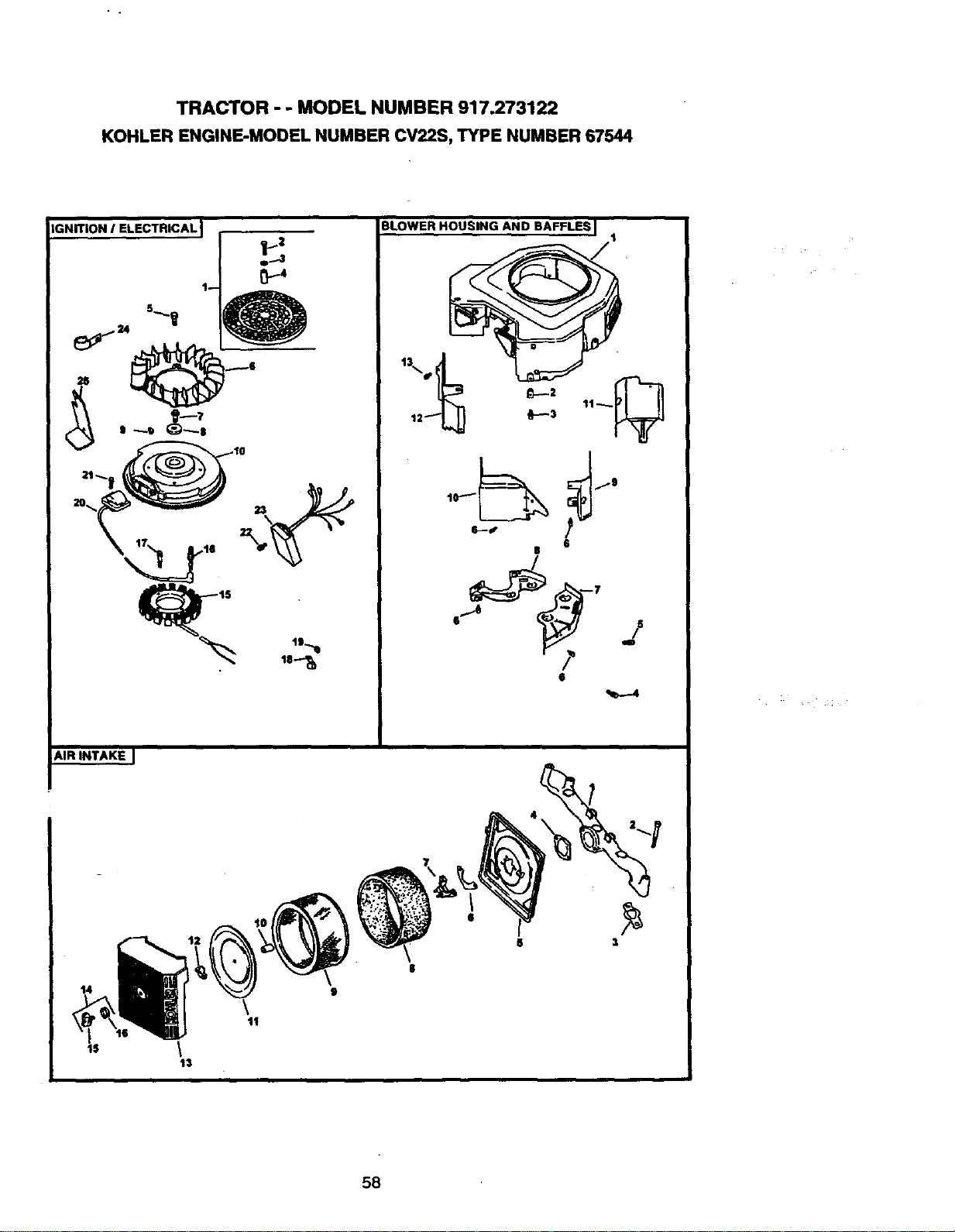
TRACTOR - - MODEL NUMBER 917.273122
KOHLER ENGINE-MODEL NUMBER CV22S, TYPE NUMBER 67544
,GNITiON I ELECTRICAL ]
AIR INTAKE I
14
\
13
11
BLOWER HOUSING AND BAFFLES I
t
0--3
6
8
' j
/-
e
58
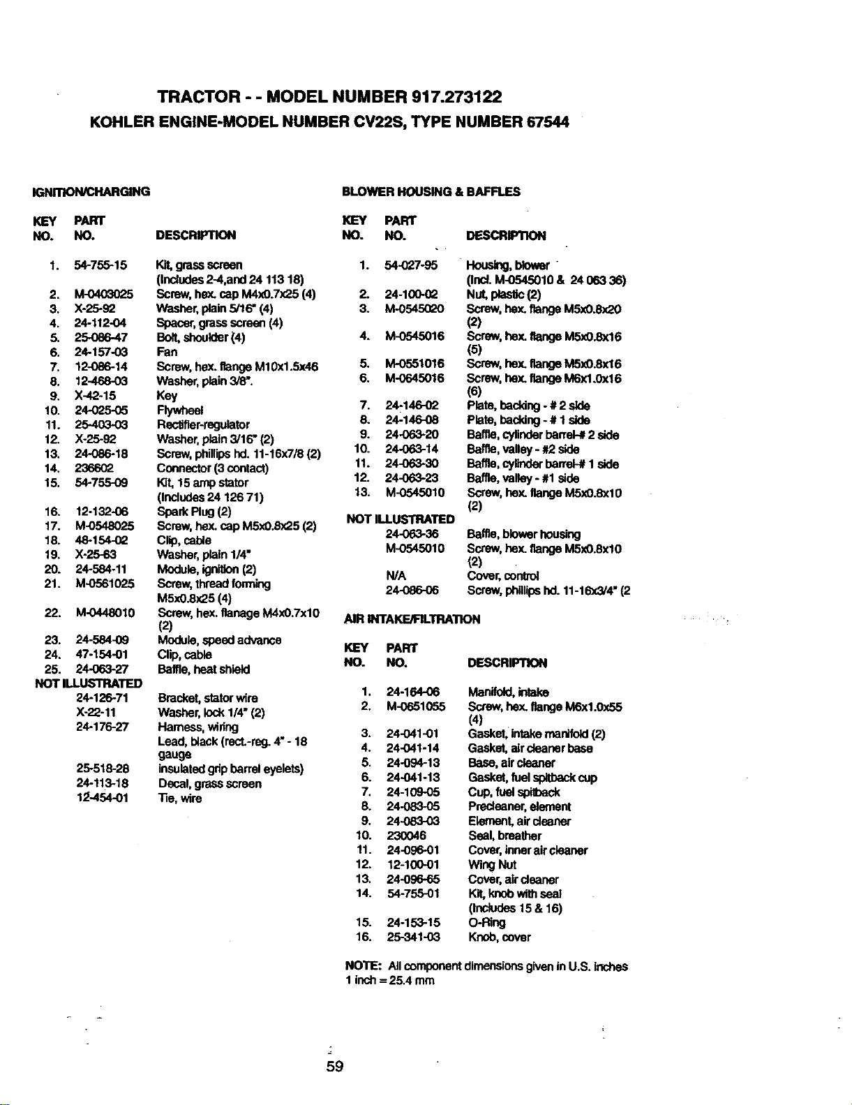
TRACTOR - - MODEL NUMBER 917.273122
KOHLER ENGINE-MODEL NUMBER CV22S, TYPE NUMBER 67544
IGNmON/CHARGING
KEY PART
NO. NO. DESCRIPTION
1. 54-755-15
2. M-0403025
3. X-25-82
4. 24-112-04
5. 25086-47
6. 24-157-03
7. 12-086-14
8. 12-468-03
9. X-42-15
10. 24-025-05
11. 25-403-03
12. X-25-92
13. 24-086-18
14. 236602
15. 54-755-09
16. 12-132-06
17. M-0548025
18. 48-154-(_
19. X-25-63
20. 24-584-11
21. M-0561025
22. M-0448010
23. 24-584-09
24. 47-154-01
25. 24-063-27
NOT ILLUSTRATED
24-126-71
X-22-11
24-176-27
25-516-28
24-113-18
1:2-454-01
BLOWER HOUSING & BAFFLES
KEY PART
NO. NO.
Kit, grassscreen 1. 54-027-95
(Includes2-4,and 24 113 18)
Screw,hex. cap M4x0.7x25 (4) 2. 24-100-0Q
Washer, plain5/16" (4) 3. M-0_
Spacer,grass screen(4)
Bolt,shoulder(4) 4. M-0545016
Fan
Screw, hex.flangeM10x1.5x46 5. M-0551016
Washer, plain3/8". 6. M-0645016
Key
Flywheel 7. 24-146-02
Rectifier-regulator 8. 24-146-08
Washer, plain3/16" (2) 9. 24-063-20
Screw, phillipshd. 11-16x7/8 (2) 10. 24-063-14
Connector(3 contact) 11. 24-063-30
Kit, 15 ampstator 12. 24-063-23
(Includes24 126 71) 13. M-0545010
Spark Plug(2) NOT ILLUSTRATED
Screw, hex. cap M5xO.Sx25(2) 24-063-36
Clip, cable M-0545010
Washer, plain1/4"
Module, ignition(2) N/A
Screw, threadforming 24086-06
M5x0.8x25 (4)
Screw, he)(.Ilanage M4xO.7xlO AIR INTAKE/PILTRA'RON
(2)
Module, speedadvance KEY PART
Clip, cable NO. NO.
Baffle,heat shield
Bracket,statorwire
Washer, lock1/4" (2)
Harness, wideg
Lead, black (rect.-reg.4"- 18
gauge
insulatedgdpbarrel eyelets)
Decal, grass screen
"lie,wire
DESCRIPTION
Hous_g, blower
(Ind. M-0545010 & 24 063 36)
Nut, plastic(2)
Screw,hex. flangeM5:d).8",QO
(2)
Screw, hex.flange M5xO.Sx16
(5)
Screw, hex.flangeM5x0.8x16
Screw, bax. flangeM6x1.0x16
(6)
Plate, backing - # 2side
Plate, backing- # 1 side
Baffle, cylinderbarrel-#2 side
Baffle, valley- #2 side
Baffle, cylinderbarreb# 1side
Baffle,valley - #1 side
Screw,bax. flangeM5x0.8xl0
(2)
Baffle, blowerhousing
Screw,hex.flange M5xO.8xl0
(2)
Cover,control
Screw,phillipshd. 11-16x3/4"(2
DESCRIPTION
1. 24-164-06 Manifold,intake
2. M-0651055 Screw,hex. flange M6x1.0x55
(4)
3. 24-O41-01 Gasket, intakemanifold(2)
4. 24-041-14 Gasket, aircleaner base
5. 24-094-13 Base, aircleaner
6. 24.O41-13 Gasket, fuel_ cup
7. 24-10905 Cup, fuel spithack
8. 24-083-05 Predeaner, element
9. 24-083-03 Element, aircleaner
10. 230046 Seal, breather
11. 24-096-01 Cover, inneraircleaner
12. 12-100-01 Wieg Nut
13. 24-096-65 Covar,air cleaner
14. 54-755-01 Kit,knobwith seal
(Includes15 & 16)
15. 24-153-15 O-Ring
16. 25-341-03 Knob,cover
NOTE: Allcomponent dimensionsgiveninU.S. inches
1inch= 25.4 mm
59
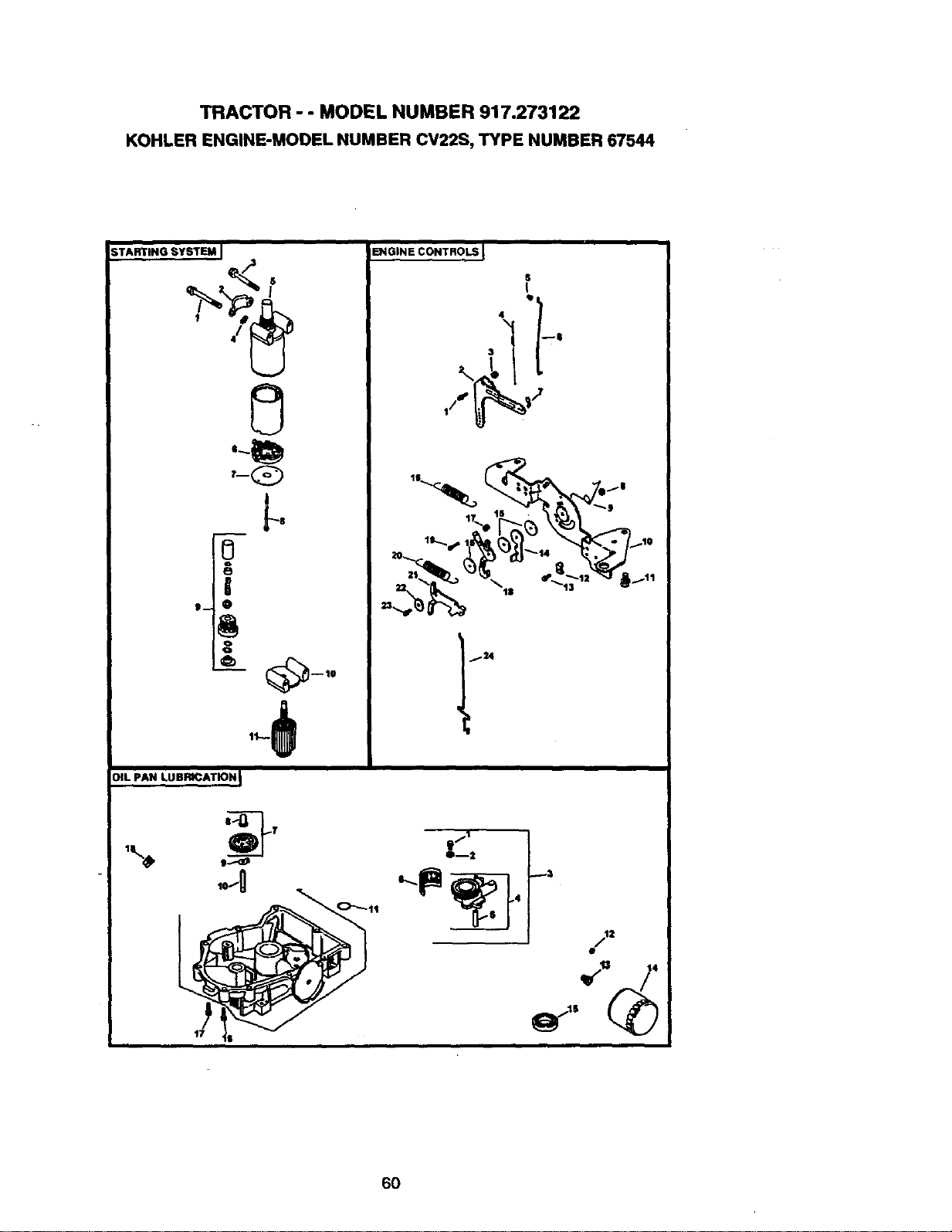
TRACTOR - - MODEL NUMBER 917.273122
KOHLERENGINE-MODELNUMBERCV22S,TYPENUMBER67544
;TARTING SYSTEM I
S
r-Q
OIL pAN LUBRICATION_
ENGINE CONTROLS
18
23
2
6O
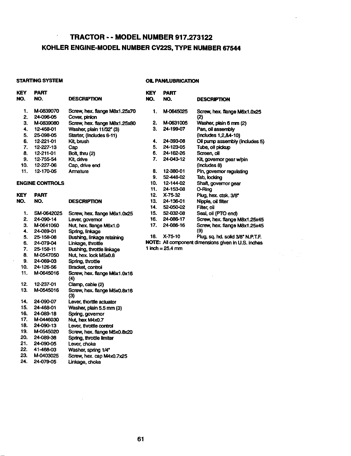
TRACTOR - - MODEL NUMBER 917.273122
KOHLER ENGINE-MODEL NUMBER CV22S, TYPE NUMBER 67544
STARTING SYSTEM
KEY PART
NO. NO.
1. M-0839070
2. 24-096-05
3. M_
4. 12468-01
5. 25-098-05
6. 12-221-01
7. 12-227-13
8. 12-211-01
9. 12-755-54
10. 12-227-06
11. 12-170-05
ENGINE CONTROLS
KEY PART
NO. NO.
1. SM-0642025
2. 24-090-14
3. M-0641060
4. 24089-01
5. 25-158-08
6. 24-079-04
7. 25-158-11
8. M-0547050
9. 24-089-03
10. 24-126-56
11. M-0645016
12. 12-237-01
13. M-O545016
14. 24-090-07
15. 24-468-01
16. 24-089-18
17. M-0446030
18. 24-090-13
19. M-0545020
20. 24-089-38
21. 24-090-05
22. 41-468-03
23. M-0403025
24. 24-079-05
DESCRIPTION
Screw,bex. flangeM8xl.25x70
Cover,pinion
Screw,hex. flangeM8x1.25xS0
Washer,plain 11/'32"(3)
Starter,(Includes5-11)
brush
Cap
Bolt,thru(2)
Kit,ddve
Cap. driveend
An'nature
DESCRIPTION
Screw, hex. flangeM6x1.0x25
Lever,governor
Nut, hey..flangeM6xl.0
Spring,linkage
Bushing,linkageretaining
Unkago,throltle
Bushing,throttlalinkage
Nut,hex. lockM5x0.8
sp_ng,throrde
Bracket,control
Screw,hex. flangeM6x1.0x16
(4)
Clamp,cable (2)
Screw,hex. flangeM5xO.8x16
(3)
Lever,thortOeactuator
Washer, plain5.5 mm (3)
Spring,govemor
NUt,bex M4xO.7
Lever,throttlecontrol
Screw, bex. flange M5xO.8x20
Spring,throttle limiter
Lever,choke
Washer, spring1/4"
Screw, hex. cap M4xO.7x25
Linkage,choke
OIL PANJLUBRICATION
KEY PART
NO. NO.
DESCRm_ON
1. M-0645025
2. M-0631005
3. 24-199-07
4. 24-393-08
5. 24-123-05
6. 24-162-26
7. 24-043-12
8. 12-380-01
9. 52-448-02
10. 12-144-02
11. 24-15308
12. X-75-32
13. 24-136-01
14. 52-05002
15. 52-032-08
16. 24-086-17
17. 24-086-16
Screw,hey, flangeM6x1.0x25
(2)
Washer,i_a_ 6 rnm(2)
Pan, oilassembly
(indudes 12,&4-10)
Oilpumpassembly(Includes5)
Tube, oilpickup
Screen,oil
Kit,governorgear w/pin
(Includes8)
Pin,governorregulating
Tab,Iocidng
Shaft,govemor gear
O-Ring
Plug,hex. ctsk.3/8"
Nipple,oil filter
Filter,oil
SeaÁ,oil(PTO end)
Screw,hex.flange M8x1.25x45
Screw, bex. flange M8x1.25x45
(9)
18. X-75-10 Plug,sq. hd. solid3/8" N.RT.F.
NOTE: All componentdimensionsgivenin U.S. inches
1 inch= 25.4 mm
61
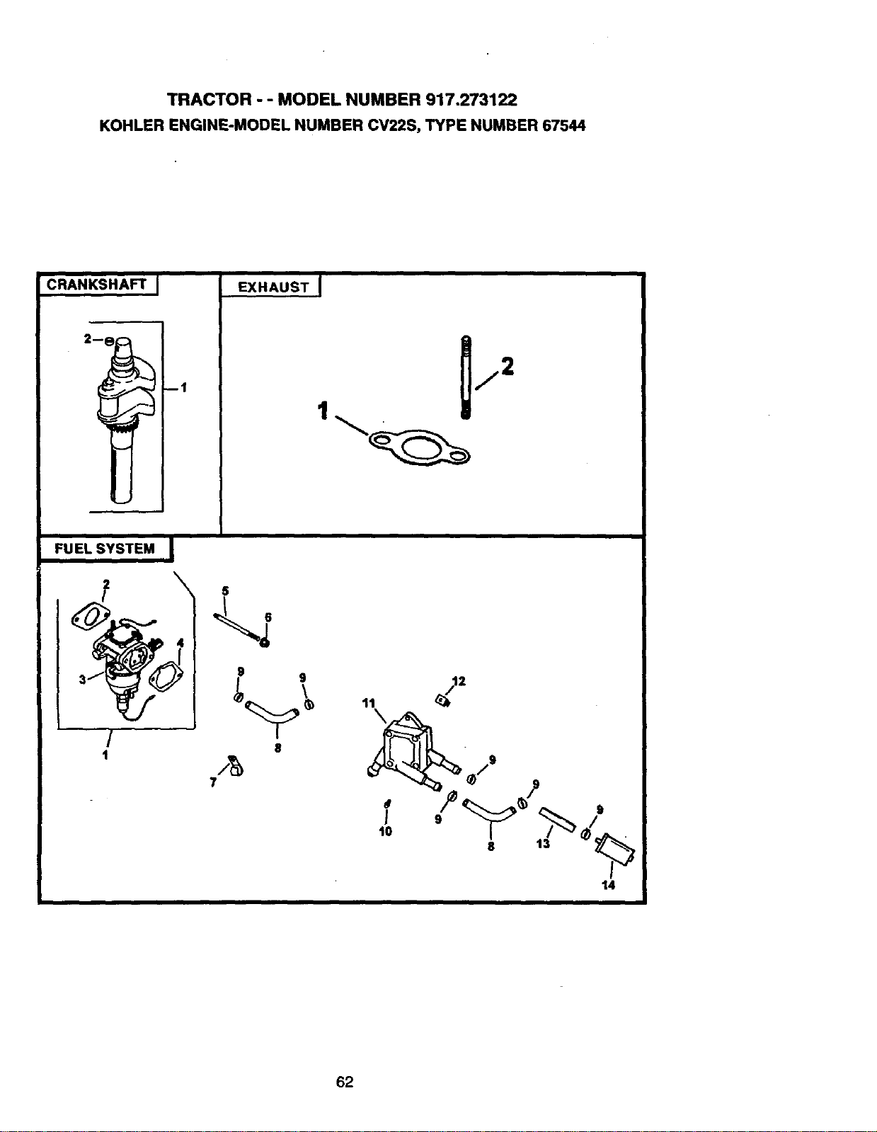
TRACTOR - - MODEL NUMBER 917.273122
KOHLER ENGINE-MODEL NUMBER CV22S, TYPE NUMBER 67544
CRANKSHAFT I
--1
EXHAUST !
1
FUEL SYSTEM ,,I
/
1
\
5
g 9
8
7
/12
11
8 13
14
i i
62

TRACTOR - - MODEL NUMBER 917.273122
KOHLER ENGINE-MODEL NUMBER CV22S, TYPE NUMBER 67544
C_N_HAFT
KEY PART
NO. NO.
1. 24-014o72
2. 52-139-09
EXHAUST
KEY PART
NO. NO.
1. 24-041-(_
2. 25-072-04
24 522 16
24 782 05
2475503
DESCRIPTION
Cmnks_ft (Indudes 2)
Plug,cup
OESCRIPTION
Gasket, exhaust (2)
Stud, M8xl.25x33 (4)
ShortBlock
Miniblock
Gasket Set
FUEL SYSTEM
KEY PART
NO. NO. DESCRIFIrlON
1. 24-853-25
2. 24-041-15
3.
5. M-062f1095
6. M-0641060
7. 47-154-01
8. 24-353-03
9. X-426-9
10. 24-086-12
11. 24-393-04
12. 24-100-01
13. 25-353-03
14. 24-050-02
NOT ILLUSTRATED
24-757-18
24-757-19
24-757-20
24-757-22
Kit,cad_umtorW/gaskets
(Includes2-4)
Gasket, carburetor
Carburetorassembly(ForInfor-
ma_ononlynot
av'ailaUeseparately)
(Incfudes24-757-18,
24-053-25 24-757-19, 24-757-
20, 24-757-22)
Stud, M6x1.0x95 (2)
Nut,he_nangeMSxl.0(2)
Cl_, cable
Une, fuel 10-5/8" (2)
Clamp, hose(S)
Screw, hex. cap. M6x1.7x18 (2)
Pump, fuel- pulse
Nut, p_sUc (2)
Une, fuel 13-1/'2"
Filter,fuel
Kit,overhaulw/gaskets
Kit,choke repairw/gaskets
K_,gasket
Kit, solenoidreplacement
w/gaskets
NOTE: AllcomponentdimensionsgiveninU.S.inches
1 inch= 25A mm
63

64

65

66

SUGGESTED GUIDE FOR SIGHTING SLOPES FOR SAFE OPERATION
SIGHTING
GUIDE
ONLY RIDE UP AND DOWN HILL,
NOT ACROSS HILL
O_
",4
I_ Operate your Tractor up and down the face of slopes (not I
I
greater than 15°), never across the face. Make tume gradu-
J
ally to prevent Upping or loss of control. Exercise extreme
caution when changing direction on slopes.

Fortherepairorreplacementpartsyou need
delivereddirectlytoyourhome
Call7am- 7pm,7daysaweek
1-800-366-PART
(1-800-366-7278)
Part= ordenar piezas con entrega a
domicil|o - 1-800-659-7084
For in-house major brand repair service
Call 24 hours a day, 7 days a week
1-800-4-REPAIR
(1-800-473-7274)
Para pedlr servicio de reparaci6n a
domicilio - 1-800-676-5811
For the location of a Sears Parts and
Repair Center in your area
Call 24 hours a day, 7 days a week
1-800-488-1222
For information on purchasing a Sears
Maintenance Agreement or to inquire
about an existing Agreement
Call 9 am - 5 pm, Monday-Saturday
1-800-827-6655
mmmmmm
mmmmmm
When requesting service or ordering
LIiRR_R_ays provide the following
"l_roTrltdfl6n:
°_l_l_.l_e • Part Number '
• --"'--,1__ocl91- _umber • Part Descriptior
SEARS
Amenca's Repair Specia/_sts
166192 9.10.98 JH Printed in U.S.A.


