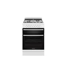
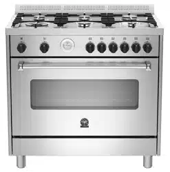
Installation and Operating Instructions upright cookers
IMPORTANT:
- This cooker is for domestic applications. It is NOT suitable for commercial applications of any kind. Do not install the cooker if there is any doubt. Contact Glem Gas Australasia if you require clarification.
- This cooker must be installed by a qualified & licensed installer in accordance with these instructions. If you do not retain proof of correct installation your warranty will be voided.
- If your cooker is found to be incorrectly installed you will be liable for all service costs. If a warranty call is made and the cooker is found to be incorrectly installed you will be charged for the service call even if the cooker is not repaired. We will not service an incorrectly installed cooker.
FIRST TIME USE
IMPORTANT
- Remove all packing material and literature from the upright cooker before connecting the gas and electrical supplies.
- A plastic film is coated on the stainless steel inside and on the outside of the cooker. It must be removed before use.
- Make sure all plastic has been removed before use. Some models have trays with a protective coating; make sure the plastic coating has been removed. To make the plastic film easier to remove we suggest using a Stanley knife to trim along joints and edges before peeling back the film.
- Clean the interior of the oven with soap and water.
- Switch on the empty oven on maximum to eliminate grease residues from manufacturing.
- There may be a slight odour at this time. Run the oven on maximum for a period of 2 hours. Open the kitchen windows at this time. If this odour lingers use the oven and the odour will dissipate.
IMPORTANT
- DO NOT spray aerosols in the vicinity of this upright cooker while it is in operation.
- DO NOT allow young children to use the cooker
- DO NOT touch surfaces when they are hot
- DO NOT store flammable materials in or under the cooker
- DO keep the cooker clean to avoid fires
This appliance is unsuitable for use in marine craft. caravans or mobile homes unless each burner is fitted with a flame safeguard.
WARNING:
- Where the cooker is installed in marine craft or in caravans. it is NOT to be used as a space heater.
- If the upright cooker fails to operate correctly. call Glem Gas Australasia Pty Ltd or their appointed agent for service. DO NOT ATTEMPT REPAIRS YOURSELF.
- Glem Gas Australasia Pty. Ltd. does not accept any responsibility for any damage coming from inappropriate. incorrect and irrational use. For more detailed information. refer to the Warranty Card.
- DO NOT MODIFY THIS APPLIANCE
- DO NOT INSTALL IF THE COOKER IS DAMAGED
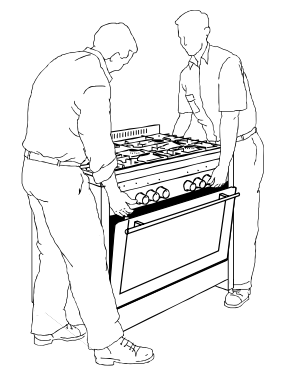
MOVING THE COOKER
When moving the cooker always use two people.
When installed this cooker complies with all safety requirements however care must be taken when moving the cooker as some sharp edges and corners that are not intended to be touched could cause injury.
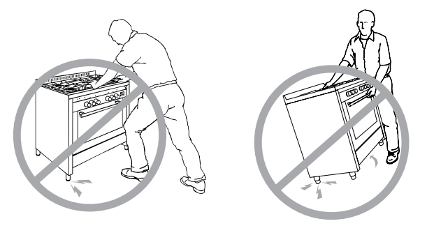
DO NOT LIFT USING THE HANDLE – open the oven door and hold inside the top of the oven cavity.
DO NOT DRAG OR SLIDE THE COOKER
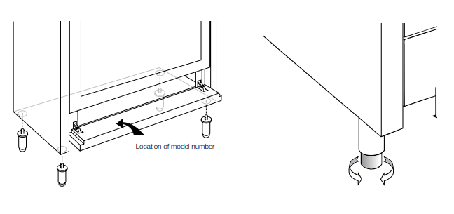
ADJUSTABLE FEET (SOME MODELS) – before installing the cooker level the appliance using the adjustable feet or legs.
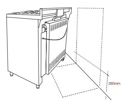
SAFETY CHAIN AND ANTI TILT BRACKETS
- The upright cookers have a safety chain to prevent damage to the gas pipes if the upright cooker is moved and anti tilt brackets to prevent accidental tipping of the cooker.
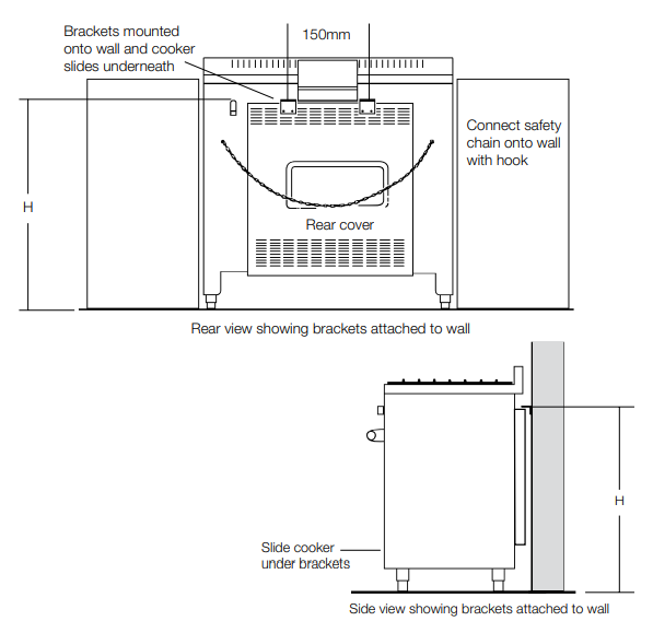
- Safety chain: The chain must be secured to the wall behind the upright cooker by fitting an expansion plug with hook to the wall at the same height as the safety chain. The chain may then be attached to the hook.

INSTALLATION OF ANTI TILT BRACKET
- Install the legs to the cooker and adjust the height to the desired level. Make sure that this height is absolutely correct to what you require.
- On the rear of the cooker there is a covering panel. Accurately measure the distance from the top of this panel to the floor Height H.
- Mark the same height on the wall against which the cooker is to be installed.
- Mark the centre of the cooker at the same height on the wall.
- At a distance of 150mm either side of the centre at the measured height mount the 2 anti tilt brackets supplied onto the wall.
- Slide the cooker into position after connecting the chain. The brackets prevent any chance of the cooker tilting forward.
After the cooker is unpacked make sure that it is not damaged. All packaging materials should be disposed of appropriately.
Cookers are hot. This cooker meets Australia Standards on external surface temperatures but the surfaces are still hot and children should not be allowed to play with the cooker at any time.
FOR SAFE USE OF THE COOKER PLEASE CONSIDER:
- Oven door: Keep children away from the glass oven door while cooking is in progress: if touched. the glass could cause burns.
- Drop down doors: Don’t let children sit down or play with the oven door. Do not use the drop down door as a stool to reach above cabinets. Do not put any weight on oven door.
- Grill: Grilling must always be done with the oven door closed.
- Pots and pan handles: Always turn pan handles to the side or to the back of the hob where they can’t be knocked or reached by children.
- Warming cabinets: Do not place inflammable materials or plastic utensils in the warming cabinet below the oven. Items in this area of the cooker can be subject to heat.
- Using the right sized pan: Using the right sized pan makes sense: saves energy and avoids burnt handles or damage to pots and the hob.
- Use of pot holder gloves: Make sure that burners and oven trays are cool before touching them unless you are wearing oven gloves.
- Precautions: Never wear loose fitting garments while burners are on. since the fabric could ignite and cause injuries. Caution should also be taken with potholders & tea towels.
- DO NOT line the oven walls or floor with aluminium foil. Do not place baking trays or anything onto the floor of the oven.
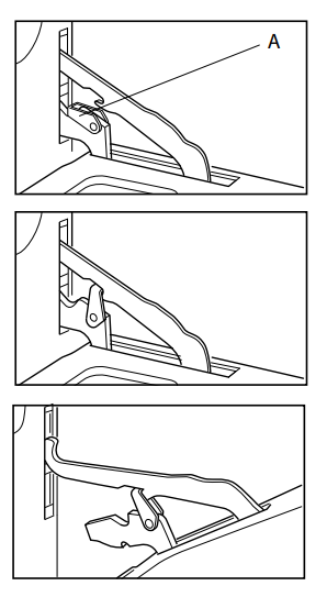
REMOVING THE OVEN DOOR AL, EI, EB and EM series
- Open the oven door completely.
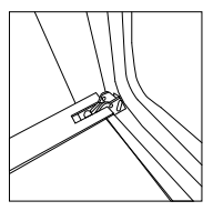
- With the aid of a small screwdriver flick up the hinge lock A on each hinge and swing it into the slot.
- Take the weight of the door and slowly partially close it until there is a certain resistance. At this point the hinge lock should lock in and allow the door to be lifted up and away from the cooker.
- TAKE CARE NOT TO DAMAGE THE HINGES - DO NOT force them.
- When replacing the door repeat the process in reverse order. Be careful to seat the hinges properly. If the door is crooked and the hinges seem tight try again.
- Check that the door is operating correctly.
MA/IT/DI/ML SERIES DOOR REMOVAL AND RE INSTALLATION
The DI and ML series of Glem and Emilia cookers have the latest oven door hinge design technology from Glem Gas. For the removal and re-installation of the oven door with the new hinges please follow these procedures.
1. Open the door fully.
2. Rotate the hinge locking tab usingyour finger or a small screw driver.

3. Tab in locked position. Repeat the procedure on each hinge.
4. Hold the door as shown.
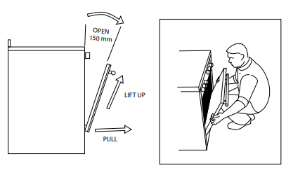
TO RE-INSTALL THE DOOR
- IMPORTANT Hold the door at an angle so there is a 150mm gap at the top.
- Hook the hinges in first with the groove in the bottom of the hinge sitting on the roller housing.
- Once the hinges are located properly fully open the door again and unlock the hinges and close the door.
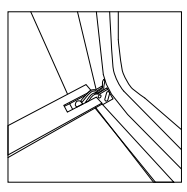
CLICK AND SLIDE INNER GLASS REMOVAL - SOME MODELS
The models with the click and slide inner glass removal can be identified by the 2 circular press points located towards the top of the inner door. This allows for easy glass removal to clean the inside of the door.
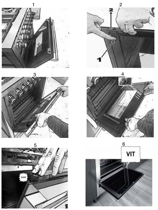
IMPORTANT: Ensure that the bottom right corner of the inner glass reads VIT.
OPERATION OF GAS HOB
GAS BURNERS: The combination of high-speed burners with those of a standard type allows all types of cooking to be achieved.
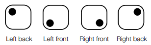
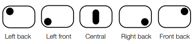
Burners Locations
Auto Flame Ignition - Some models
- To ignite any burners simply depress the corresponding control knob and rotate anti clockwise to the high flame position. As the knob is rotated the gas begins to flow and the electrode begins sparking.
Separate Electronic Ignition - Some models
- To ignite any burners, press ignition button first (the igniter should begin sparking), then simply depress the corresponding control knob & rotate anti clockwise to high flame position.
- Warning: make sure all the burners are on OFF position (outside the one that you want to light) before pressing the electronic ignition. Please note - the ignition button is a spongy & sensitive button and does NOT need to be pressed hard. Pressing hard & roughly on this button can result in breakage.
- In case of ignition malfunction or electricity failure a match can be used to ignite the burners. Strike a match and place it close to the selected burner. Depress the corresponding control knob and turn it anti clockwise to maximum flame.
Burners with Flame Failure Device - Some models
- If flame is accidentally extinguished. the flame failure device will cut out the gas to prevent gas leakage. To light these burners hold the knob in for a few seconds after the burner is lit.
ELECTRIC COOK TOP
SOLID HOTPLATES
- The solid cast hotplates are sealed all around which means that spilt liquids cannot penetrate under the hotplates.
- Rotate the knob to the position required for the needs of the cooking; the higher the number. the higher the heat. The plates marked with a central red spot are rapid heating elements.
- Cleaning: For normal cleaning use a moist cloth and for very dirty hotplates use a domestic cleaner. After cleaning run the hotplate for a short time to dry the hotplate completely. Be careful around the printed graphics and only wipe these with a damp cloth.
CERAMIC HOTPLATES
- This cook top is made from ceramic glass. The cook top can hold heavy utensils but can be broken by being hit with sharp objects.
- When a hotplate is on, the hot surface warning light will come on and remain on until the surface temperature falls below 60 degrees celsius.
Extendable Zones
- The ceramic cooktop has extendable zones to allow for the heating of larger sized pans.
- Extendable zones are indicated by a second line around the cooking zone. To activate the extended zone rotate the appropriate control knob to maximum and then past maximum for a moment and the extended zone will function. To return to the smaller zone rotate the knob to off and it will revert to the smaller zone.
Cleaning
- Remove all spilt food with a razor blade scraper while the hotplate is still warm, NOT HOT.
- If aluminium foil, sugar or plastic melt onto glass use a razor blade scraper immediately to remove immediately before the hotplate has cooled to avoid pitting.
- When the ceramic hotplate has cooled, wipe clean with detergent on a clean cloth.
- Do not use sponges or scourers on ceramic hotplates. Pitting, staining or scratching will NOT be covered by warranty.
- WARNING: CERAMIC COOK TOPS - if the surface is cracked switch off the appliance and call for service to avoid any possibility of electric shock.
OPERATING THE GAS OVEN
The oven is equipped with a gas thermostat. Its purpose is to keep the temperature as a constant heat. The oven is fitted with electronic spark ignition and a safety shut off device.
Lighting the Oven
- First open the oven door and remove the grill tray. Leave the grill tray out while operating the oven.
For automatic ignition models
- Press the oven control knob and rotate anti-clockwise to the maximum heating position. The electronic ignition is activated automatically when the knob is depressed. Keep the knob depressed for about 15 seconds after the flame has lit. Always view the burner during lighting procedure for safety. There is a hole in the bottom panel of the oven for viewing the burner.
For separate electronic ignition models
- Press ignition button first (the igniter should begin sparking), then simply depress the oven control knob & rotate anti clockwise to maximum heating position. Keep knob depressed for about 15 seconds after the flame has lit.
- Always view the burner during lighting procedure for safety. There is a hole in the bottom panel of the oven for viewing the burner.
Ignition Malfunction
- In case of ignition malfunction or electricity failure depress and turn the oven knob in an anticlockwise direction to reach the maximum heating positioning.
- Light a match and place it near the hole in the base panel, keep the knob depressed. Once the burner is lit keep the knob depressed for 15 sec.
- NOTE: When lighting the oven for the first time - if the electronic ignition fails to light the oven light the oven manually and run the oven in by running it at 200 degrees for 20 minutes.
GENERAL WARNINGS
- WARNING avoid touching the heating element inside the oven.
- DO NOT USE polyunsaturated oils with cooking in the oven. The type of oil can cause heavy deposits inside the oven.
- DO NOT USE a steam cleaner to clean the cooker.
- TO CLEAN YOUR COOKER Do not use strong detergents or acides as this can cause rust spotting.
Oven Preheating
- After the oven has been switched on, keep the door open for a minute then close the door gently so there is no risk of extinguishing the flame. Set the oven knob to the required temperature and wait for about 20 minutes before introducing the food. Comply with the cooking indication chart in these instructions to get the best out of the oven and choose the right shelf position.
- Please note: Gas oven models do not have an indicator light for oven mode. WARNING: Do not use oven base panel as a shelf, always make use of the oven shelves. WARNING: Do not use oven base panel as a shelf. always make use of the oven shelves.
Removing and installing the oven shelves
- Slide the oven shelves towards you until they reach the front stop.
- Tilt them up at the front to clear the side supports and lift them clear.
- To install the shelves reverse the operation ensuring that the shelf is correctly installed so the stops prevent the shelf sliding out in one action.
- NOTE: All ovens are different and your new oven may perform differently to your previous model. Shelf positions and operating temperatures may vary to what you are accustomed. It sometimes takes a few uses to become fully familiar with the characteristics of your new oven.
- NOTE: Some cookers have a cooling fan that continues to run after the end of the cooking cycle.
ELECTRIC GRILLING ELEMENT
- All cookers have an electric grill within the oven compartment. On fan forced electric oven cookers the grill function is beyond the top temperature on the temperature control knob. Rotate the knob to the grill symbol.
- On gas oven cookers the grill is operated by a separate button. On electric oven models the grill control is on the oven function selector knob.
- The oven door must be closed during grill operation. Once the oven has been switched off, always wait a few minutes before switching on the grill.
- The grill element is an infrared type, which provides an even controlled heat. When the grill is on an indicator light will come on.
- Using a standard shelf with a drip tray below filled with some water will avoid smoke build-up coming from burnt fat and at the same time assist in keep the food moist.
- NOTE: Always grill with the oven door closed - the oven and grill cannot be operated at the same time.
OPERATING THE ELECTRIC OVEN
Multifunction Electric Oven - some models
Remove grill tray. Choose a function using the selector knob. Turn it to the symbol of the cooking function you wish to use. Then rotate the thermostat knob to the desired temperature. Wait until the thermostat indicator light goes off – this indicates that the oven has reached temperature. Then introduce the food to be cooked. Below is a description of each of the functions
 Oven light - the oven light switches on
 Defrosting only the fan operates - defrosting times reduce by approximately 1/3.
 Static convection mode (conventional cooking) - Heat is supplied from above and below using natural convection. The oven must be preheated before food is placed inside. Static convection is ideal for cooking foods that need to be heated steadily internally and externally. Use for roasts, spare ribs, meringues.
 Fan Assist - Top and bottom element operate with the fan operating. This function circulates hot air from the top to the bottom element. Great for large quantities and volume of food such as turkeys. chickens. cakes etc.
 Fan Forced - the circular heating element and the fan come into operation and the heat is distributed evenly to all levels of use. Fan mode is ideal for cooking foods that must be well done on the outside and tender or rare on the inside. Heat is supplied from every direction, cooking is possible on several shelves, it provides high moisture removal, defrosting is possible with or without eat. Rotation of food during cooking is sometimes required.
 Static Grill Closed door grilling at all times. The infrared element operates. The infrared element operates. Recommended operation is only for 30 minute periods. Position the shelf at the desired level. Great for browning, crisping and toasting
 Grill with Fan - the action of the fan combined with the powerful action of the two grill elements is ideal for cooking large pieces of food. Closed door grilling at all times. Great for steaks.
N.B: The thermostat pilot light switches on and off during cooking to show that the heating cycles are taking place properly. For Static and fan forced mode, the oven must always be preheated. For optimum results, try to open the oven door as little as possible, opening the door lowers the temperature suddenly and affects the thermostat cycles. When cooking on different shelves simultaneously, put all containers in the centre of the shelves.
Rotisserie: On the ML 106 cooker there is a rotisserie feature in the small oven. The rotisserie motor operates when the grill function is selected. Operate the rotisserie with the door closed.
COOKING TABLE
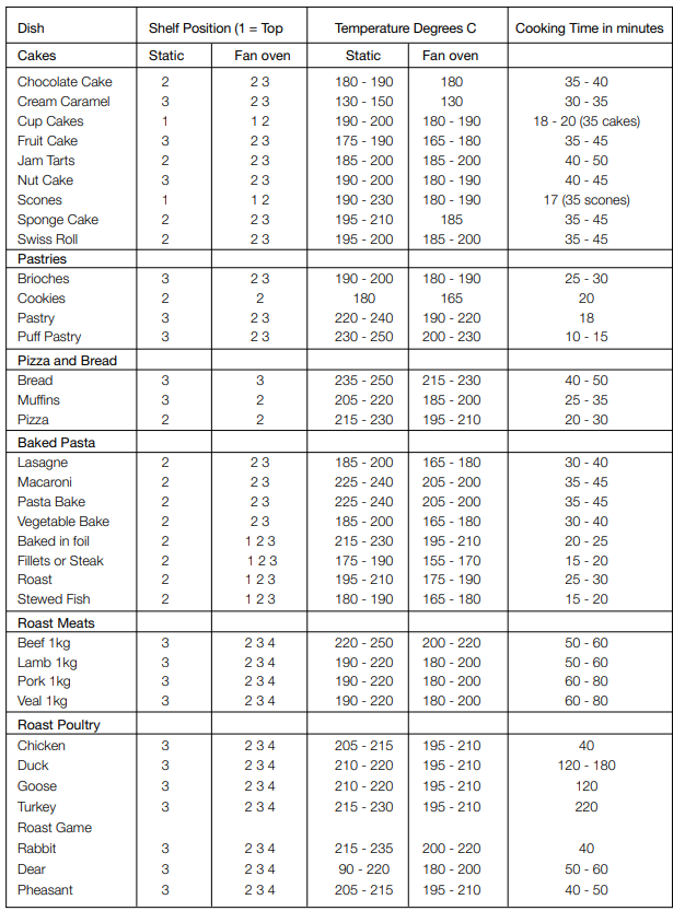
Notes:
- The information provided is purely a guideline. Modify to suit experience, eating habits and personal taste.
- The times indicated in the table do not include preheating of the oven, which is always recommended.
- The time and temperature indicated refer to average quantities of food: meats 1/1.5kg, dough for confectionery, pizza, bread 0.5/0.8kg.
- Information in brackets with regard to shelves indicates the shelf to be used when cooking several dishes together.
- When cooking on different shelves simultaneously put all containers in the centre of their shelves.
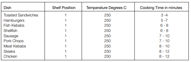
Notes:
- For recipes where this is required, a preheating period of 4-5 minutes will be sufficient.
- The times indicated in the table refer to one side of the piece of food only; it must then be turned over.
- Always keep the oven door closed when grilling.
- For optimum results try not to open the door too far when turning food.
- All food for grilling must be placed on the grill. Place the juice and dripping tray on the second pair of rails.
IMPORTANT: Never cook on the bottom base panel.
NOTE: All ovens are different and your new oven may perform differently to your previous model. Shelf positions and operating temperatures may vary to what you are accustomed. It sometimes takes a few uses to become fully familiar with the characteristics of your new oven.
NOTE: Some cookers have a cooling fan that continues to run after the end of the cooking cycle.
BAKING TROUBLE SHOOTING
1. Cooking unevenly
Wrong location in oven
- Use shelf to place food in centre of oven
Wrong size tray
Heat variations in oven
2. Burning on top
Oven not preheated
- Turn oven on and wait for light to go off before placing food in the oven
Aluminium foil in oven
Baking tins too large
- Use correct size according to recipe and place away from oven wall
Food too close to top of oven
3. Burning on bottom
Temperature too high
Baking tins too large
Baking tins are dark coloured
- Use light coloured tins or reduce temperature
Food too low
- Use higher shelf position
Opening oven door too frequently
4. Meat and potatoes
Poor heat distribution on food
- Place food onto a rack to allow heat all not browning around
5. Cakes have hard, split crust, seem overcooked
Temperature too high
Food too high in oven
Cake tin too deep
Cake tin too dark
6. Cakes sunk in centre, seem under cooked
Temperature too low
Baking time too short
Door opened too early
- Do not open door until late in the cycle
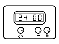
Setting the clock
- When the oven is first connected, or after a power failure, ‘0.00’ will flash on the display. To set the clock, push the TIMER ON/OFF button, then the (+) or (–) buttons immediately. The time of day will be saved after 10 seconds.
Using the timer
- The timer can be set for a maximum period of 99 minutes and a minimum of 1 minute.
- To set the timer, push the (+) or (-) button until you have set the required time. (wait 10 seconds if you have just set the time of day)
- When the timer is operating the TIMER ON INDICATOR WILL BE LIT Once the pre-set time has elapsed, the timer will beep
- Push the TIMER ON/OFF button to switch off.
Changing the volume of the beep
- The (–) button can also be used to change the volume of the beep. Set the timer for one minute. When the beep sounds use the (–) button to adjust the volume.
OPERATION OF THE TOUCH CONTROL PROGRAMMER – GLEM ML COOKER MODELS ONLY
- If your cooker is fitted with the Touch control programmer then you have the latest in cooker timers. The touch control digital programmer has the following features:
- Minute minder - sets a countdown time that beeps when the set time has elapsed.
- Automatic cooking time - the timer counts down the preset cooking time, turns the oven off and beeps when the time has elapsed. Delayed start cooking time – the timer sets how long the oven runs for and the time of day that the oven switches off.
GETTING STARTED
- When you first connect the power the display will flash on and off. This is normal. Your cooker is fitted with a touch control timer programmer. The timer has a key lock function and to activate it a key must be pressed for 2 seconds. After that it operates immediately and if left for 8 seconds reverts to key lock.
SETTING THE TIME OF DAY - First set the time of day before you operate your appliance.
- Press the bars at positions “+” and “-” at the same time and hold down.
- The centre dot will start to flash on and off.
- While it is flashing use the “+” and “-” to set the time. If you hold your finger down the clock will scroll much faster. The clock has a 24-hour display.
- Once you reach the correct time of day leave it for a few seconds it will beep and the clock will be set.
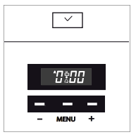
SETTING THE MINUTE COUNTDOWN TIMER - The minute countdown timer works independently of the oven and is handy for checking time periods for all cooking tasks.
- Press MENU and hold down until the screen changes and then let go.
- Set the countdown time you want by pressing the “-” or “+”. The time is in minutes not seconds.
- There will be a beep and the timer is set. You will see the time of day and the bell icon on the clock display.
- Once the countdown is completed a beeper will sound. Press any button to switch off the beeper. To stop the bell icon flashing press and hold MENU. If you want to check the amount of time remaining in this mode just press and hold MENU once. If you want to cancel at any time press and hold the MENU until the screen changes and then hold the + and – at the same time. The timer will be cancelled
SETTING THE AUTOMATIC OVEN SWITCH OFF - On electric ovens this function allows you to set the length of cooking time.
- Switch the oven to the function and temperature you want to use.
- Press and hold MENU and then press it again. The display shows “DUR” (for duration).
- Press + to set the desired cooking time. Wait for a moment and the timer will beep and return to time of day.
- Once the time period is complete the oven will switch off and the beeper will sound.
- Press any button to switch off the beeper. If you wish to cancel at any time during the cooking period press and hold the MENU, press it again and then the + and – at the same time. Do not forget to switch off the oven and temperature setting at the end of the cycle
PROGRAMMING THE OVEN TO SWITCH OFF AT A CERTAIN TIME OF DAY - Sometimes it is handy to set the time of day you want to finish cooking such as heating a casserole for dinner. This feature allows you to set the length of time you want the oven to run and the time of day when you would like the oven to turn off.
- Press and hold MENU and then press again. The display shows “DUR” (for duration).
- Press + to set the desired cooking time.
- Press MENU once to show “END” in the screen. This is where you set the time of day that you want the oven to finish cooking.
- Press the + to set the time of day when you wish for the cooking to stop.
- Turn on the oven and select the oven function. Of course the oven doesn’t switch on yet.
- The oven will switch off at the end of the period and the beeper will sound.
- Press any button to switch off the beeper. If you wish to cancel the program at any time press and hold the MENU then press MENU twice and then the + and – at the same time. Do not forget to switch off the oven and temperature setting and the end of the cycle.
PROGRAMMING EXAMPLE: I wish to use fan forced setting at 180 degrees to cook for 45 minutes including heat up and to finish cooking at 12.30 in time for lunch.
- Press MENU and hold then press again - “DUR” displays.
- Press + to 45 minutes
- Press MENU once – “END” displays
- Press + to 12.30
- Press MENU once to go back to time of day.
- Select FAN FORCED function.
- Set temperature at 180 degrees.
HANDY HINTS
- Remember to include the heat up time when programming the oven.
- The oven programmer only operates for the electric oven, it does not operate for gas oven functions.
- Remember to turn off the oven at the end of an automatic cycle.
CLEANING AND MAINTENANCE
WARNING: the oven and hob must be kept clean, as a build up of fat constitutes of a fire risk
- Cleaning of Stainless Steel: In order that your cooker retains its new appearance, care should be taken to protect the stainless steel finish. Never use gritty or abrasive sponges. We highly recommend stainless steel cleaners and protectors. Stubborn stains can be removed by soaking in hot water and stains can be prevented by using a clean cloth soaked in soapy water before a spillage becomes cold or dries up. Acid materials like milks, vinegar, citrus juice can damage the most resistant surfaces. If a spill occurs wipe it up immediately.
- Oven Cleaning: Oven spills should be cleaned straight away. Leaving them will cause burning and smoking inside the oven the next time it is used. Leaving spills can also cause permanent damage to the enamel and make it extremely hard to remove later. A non-caustic cleaner is recommended such as non caustic “Mr. Muscle” to clean the chamber of the oven. Do not use abrasive scourers, sponges or cleaning products. Wipe the oven out regularly while the oven is still warm using hot soapy water and a soft cloth. The removal of side shelves supports makes cleaning easier.
- Gas Burners - All models: The burners can be removed from the cooker and cleaned in hot soapy water. The burner covers are made of cast iron so as soon as they are cleaned dry burner covers immediately to prevent rusting. Enamelled trivets are also recommended to be cleaned in hot soapy water or the dishwasher. Make sure all pieces are completely dry before placing them back onto the cooker.
- Knobs and Control Panel - All models: All knobs are removable. Clean behind the knobs and around the control panel to prevent grease and grime build up that can cause jamming of the knobs/gas taps etc. The stainless steel panel should be cleaned with stainless steel cleaners, do not use anything abrasive.
- Cleaning of Oven Door - All models: The inner door glass is held in by a number of screws and brackets, they can be removed and the glass taken out to allow cleaning in between the two sheets of glass. The glass can be soaked in hot soapy water or special glass cleaners. The outer glass should be cleaned with a specific glass and mirror cleaner. Soapy water will remove stains and but may leave streaks. Do not use abrasive or aggressive cleaners on aluminium door frame components, if in doubt contact Glem Gas for advice.
- Removal of Side Shelf Supports - All models: The sides racks are removed by simply flexing the bottom rail off the support and unhooking at the top. To replace just reverse the procedure.
- Grill Element/Top Element - All models: This element must never be sprayed with any detergents. A damp cloth and a bottlebrush can be used to clean the roof of the oven and the element itself. Never soak the element and always dry it after cleaning as not doing so can lead to deterioration. It is important to clean this area regularly as fats spit up and stick to the ceiling and element while grilling and they may burn, smoke and give out unpleasant odours.
WARNING: please follow these safety precautions.
Avoid the ignitors becoming wet, as this is an electrical part and moisture can cause it to malfunction.
Avoid water spilling into hob burner holes when burners have been removed.
Always dry unit before use, never let water and detergents sit in and on unit.
CARE OF CATALYTIC LINERS
- Some models have catalytic liners installed within the oven cavity. They are the matte finished light coloured panels on the sides and the matte finished panel at the rear of the oven.
- They work by collecting the grease and oil residues that occur during cooking. The liner self cleans by absorbing fats and oils and burning them to ash which is then easily removed from the floor of the oven with a damp cloth.
- The liner may discolour with age and should a large amount of fat be spilled onto the liner it may affect its efficiency. To overcome this problem set the oven to maximum temperature for about 10 - 20 minutes. Catalytic liners are designed for a working life of about 300 hours.
- When the oven is cool wipe out the floor of the oven.
- Manual cleaning of the catalytic liners is not recommended. Damage will occur if soap impregnated steel wool pad or any other abrasives are used. We also do not recommend the use of aerosol cleaners on the liners.
- If the walls of a catalytic liner are no longer effective you can remove the surplus grease with a soft cloth or sponge soaked in hot water then go through the cleaning cycle as described above. The lining must be porous to be effective. Catalytic liners are designed for a working life of about 300 hours.
INSTALLATION INSTRUCTIONS
These instructions are for the use of a qualified installer only
Statutory regulations
- This appliance is to be installed in accordance with the manufacturer’s installation instructions, local gas fitting regulations, applicable building codes, electrical wiring regulations, and according to the installation code for Gas Appliances AS5601/AG6O1. Consult SAA wiring rules as appropriate.
Safety Warnings About Installation
- The cooker must be installed and serviced by a qualified technician.
- A certificate of compliance must be supplied by the installer and kept by the customer.
- All packaging materials including protective plastic film must be removed before the cooker is installed.
- The pipes used in installation must have sufficient loops to allow for the cooker to be moved for service.
- The safety chain must be fitted.
- The cooker must not be lifted or pulled using the oven handle
- The cooker must be serviced and checked every 3 to 4 years depending on usage or condition.
Minimum Clearances
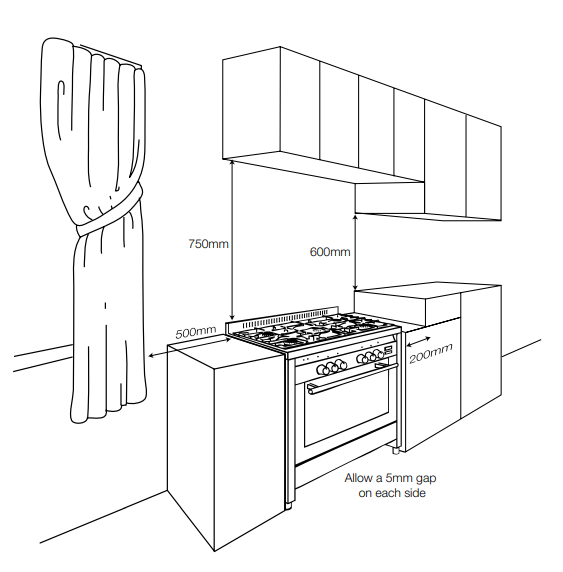
When the upright cooker is installed abutting a side or rear wall, the wall must be of non-combustible material, eg ceramic tiles. The following minimum clearances to combustible materials must be observed:
- Minimum clearance from hotplate to side wall must be 200 mm.
- Minimum clearance from hotplate to rear wall must be 200 mm.
- Minimum clearance from hotplate to cupboard above hob burners must be 600 mm.
It is recommended that the adjacent kitchen surfaces should be capable of withstanding temperatures of 100°C.
Rangehoods
- Rangehoods and overhead exhaust fans must be installed according to manufacturers’ instructions but in no case shall clearance from hob burners be less than 600 mm for a rangehood and 750 mm for overhead exhaust fan.
Ventilation
- A cooker should not be installed in any room which has a volume less than 5.6 cu. m. (200 cu. ft.). If the room is between 5.6 Cu. m. (200 cu. ft.) and 11.2 cu. m. (400 Cu. ft.) in volume, provision must be made for permanent ventilation. Above 11.2 cu. m. (400 cu. ft.) volume, no special provision needs to be made unless other gas burning appliances are installed in the same room. Ventilation must always be provided if a cooker is installed in a cellar or a basement. The manufacturer does not accept damage caused directly or indirectly by failure to comply with the above.
1. Location of gas inlet - Bottom rear of upright cooker:
- 100 mm from RH side
- 200 mm from base without legs installed
2. Electrical connection
- Connection is by means of flexible cord and plug except for electric models which must be hard wired.
3. Overall dimensions of upright cooker
- Depth over cabinet 600 mm
- Height over hob 760/750 mm (CHECK MODEL)
- Height over splashback 820 mm
- 534 series width 530 mm
- 664 series width 598 mm
- 865 series width 798 mm
- 965 series width 898 mm
- 765 series width 698 mm
- ML76 width 698 mm
- ML96 width 898 mm
- ML106 width 998 mm
On models with removable legs add up to 150 mm.
The adjustable legs are screwed into the base of the cabinet and the height adjustment is achieved by rotating the lower portion of the legs clockwise or anti-clockwise as appropriate.
Glem Gas Australasia Pty Ltd and their appointed agents decline any responsibilities in the case of installation not according to these instructions.
INSTALLATION - ELECTRICAL CONNECTION
Before connecting the plug into the power socket, follow these instructions:
- The electrical supply for the upright cooker must be a 240 Volt 50 Hz.
- The fuse and electrical wiring of the dwelling must support the load of the appliance.
- The 3-pin plug, used to connect the electricity, must be easily reached when the upright cooker is in its installed position.
- The upright cooker must be earthed. Connect the upright cooker to a properly earthed and rated power socket, as appropriate.
- The flexible cord of the upright cooker must not be subject to direct heat and must be positioned after installation so that its temperature does not exceed 75°C.
IMPORTANT: If a power socket needs to be installed or relocated, the work must be done by a licensed electrician.
IMPORTANT: For models supplied without a plug a means for disconnection shall be incorporated in the fixed wiring according to the wiring rules of the local electrical authorities.
In New Zealand the cooking range must be connected to the supply by a supply cord fitted with an appropriately rated plug that is compatible with the socket-outlet fitted to the final sub-circuit in the fixed wiring that is intended to supply the cooking range.
INSTALLATION - GAS CONNECTION
- These technical instructions have been prepared for use by Authorised persons. This unit MUST ONLY BE INSTALLED BY AN AUTHORISED PERSON – PROOF IS REQUIRED FOR WARRANTY SERVICE CLAIMS.
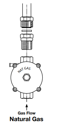
- The cooker has been manufactured with Natural Gas injectors fitted. For use with LPG the cooker must be converted. The conversion kit is supplied. Information on converting the cooker is included with these instructions.
- The requirements of the local gas and electrical authorities must be adhered to, consult AS5601 as appropriate.
- Gas inlet fitting is 1/2” BSP (male) thread.
- This appliance can be connected with rigid pipe as specified in AS5601 table 3.1.
- This appliance is approved for hose connection in compliance with AS5601, clause 5.12.1.8. The flexible hose must comply with AS/NZS 1869 (AGA Approved), 10mm ID, class B or D, between 1 – 1.2 m long and in accordance with AS5601 for a high level connection. The hose should not be subjected to abrasion, kinking or permanent deformation and should be able to be inspected along its entire length. Unions’ compatible with the hose fittings must be used and all connections tested for gas leaks.
- The fixed consumer piping outlet should be at approximately the same height as the cooker connection point, pointing downwards and approximately 150mm to the side of the cooker. The hose should be clear of the floor when the cooker is in the installed position. Ensure that the safety chain is installed correctly so that the chain prevents strain on the hose connections when the cooker is pulled forward.
- If the connection is for natural gas the test point pressure should be adjusted to 1.00kPa with the wok burner operating at maximum.
GAS CONNECTION
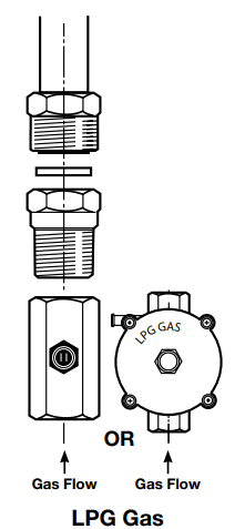
If installing for use with LPG ensure that an AGA approved gas regulator suitable for a supply pressure of 2.75kPa is part of the tank supply and the test point pressure is adjusted to 2.75kPa.
- There is a connection kit supplied with the cooker. The extension tube must be attached to the inlet elbow on the cooker. At the other end of the tube attach the regulator (for Natural Gas) using the brass conical adaptor with the sealing washer. Use two spanners to tighten to prevent strain on the inlet tube.
- It is recommended that an isolating valve and union be fitted, to enable simple disconnection for servicing. These are to be in an accessible location.
- Check connections are gas tight with soapy water or other approved method.
- Under no circumstances use a naked flame in checking for leaks.
- Check Gas Adjustments (refer installation - gas checks and adjustments).
- When satisfied that the upright cooker is operating correctly, instruct the customer in its safe operation. Ensure the customer understands fully by having them operate the upright cooker in all its functions.
GAS CHECKS AND ADJUSTMENTS - AIR SETTING
Oven burner
GAS CHECKS AND ADJUSTMENTS - LOW FLAME SETTING
Check the low flame setting for each hob burner and the oven burner with the control engaged in the minimum position.
Hob Burner
- Turn the control until it engages in the minimum position and remove the control knob. Insert a screwdriver in the adjusting screw (located to the side of the gascock shaft). To increase the flame, turn the adjusting screw anticlockwise. To decrease the flame, turn the adjusting screw clockwise. Adjust for a minimum, stable and clear flame. ENSURE THE MINIMUM FLAME WILL NOT BE EXTINGUISHED BY AIR DRAUGHTS.
Oven Burner
- Light the oven burner and operate at maximum for 15 minutes. Turn the control until it engages in the minimum position and remove the control knob. Insert a screwdriver in the adjusting screw (located to the side of the gascock shaft or in the centre of the shaft).
- To increase the flame, turn the adjusting screw anticlockwise. To decrease the flame, turn the adjusting screw clockwise. Adjust for a minimum, stable and clear flame.
- Ensure the minimum flame will not be extinguished when the oven door is closed.
FINAL CHECK
Operate all cooker burners on high and low flames and check that each burner ignites properly and has a stable flame. The following may be considered to be abnormal:
- If the burners have yellow tipping.
- If the pots are sooting up underneath.
- If the burners are extinguished by opening and closing the oven door.
- If the burners fail to ignite properly.
- If the burners fail to remain alight.
- If the electrodes constantly click when burners are alight.
When satisfied with the operation of the cooker, please explain to the user the correct method of operation. If the cooker fails to operate correctly, contact your local service agent.
Gas checks and adjustments -igniter operation
- Check that the igniter for each burner successfully ignites the gas and that the burner remains alight. If an igniter fails to work or a burner fails to remain alight, first remove the plug from the electrical power outlet, and then check that all the electrical connections are in place. If the upright cooker fails to operate correctly, call Glem Gas Appliances Pty Ltd or their appointed agent for service. Do not attempt repairs yourself.
Gas checks and adjustments -pressure adjustment
- First shut off the gas to the appliance. Remove the sealing screw from the regulator test point at the rear of the cooker and attach the hose from the mamometer to the point.
- Turn the gas back and light the largest burner and smallest burner at the maximum setting. Check the pressure and adjust at the regulator if necessary to the settings in the table or on the data plate. For propane gas adjust at the regulator at the cylinder. Turn regulator adjusting screw clockwise to increase pressure and anti clockwise to reduce pressure. Refit the test point sealing screw when finished.
- NOTE! THIS COOKER MUST BE INSTALLED BY A LICENSED GAS FITTER. WRITTEN PROOF IS REQUIRED FOR WARRANTY SERVICE.
- STANDARD PLUMBERS TEFLON TAPE SHOULD NOT BE USED TO SEAL JOINTS. AN APPROPRIATE GAS SEALING TAPE OR COMPOUND SHOULD BE USED.
Gas conversion
- If the appliance is to be used with another gas type, either Propane Gas or Natural Gas, it must be converted by an Authorised Person. Contact Glem Gas Australasia Pty Ltd or their authorised agent for details.
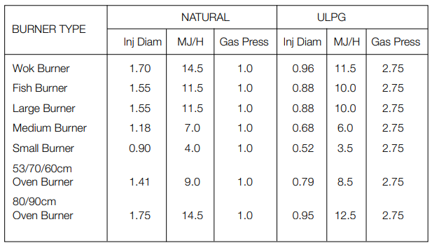
- The tables below shows the appropriate injector sizes for either Propane Gas or Natural Gas.
- IMPORTANT: After conversion check the GAS PRESSURE and IGNITER OPERATION for the Burners. If the upright cooker cannot be adjusted to perform correctly, or if there is excessive flame discolouration, yellow tipping or excessive noise contact Glem Gas Australasia Pty Ltd or their authorised agent for advice.
TABLE FOR THE CHOICE OF INJECTORS