© Panasonic Corporation 2015.
Order No: PAPAMY1503085AE
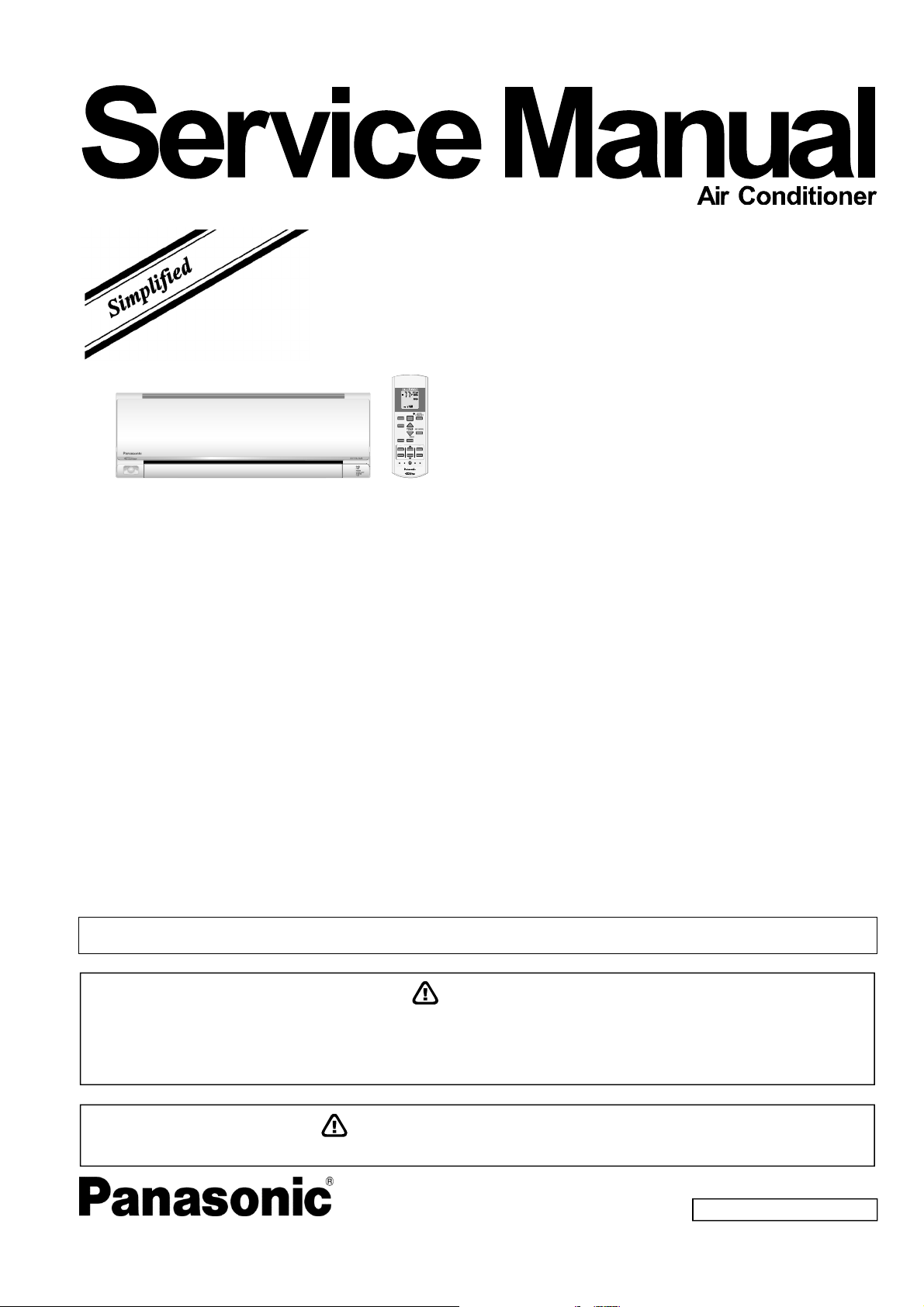
Indoor Unit
CS-ME5RKUA
CS-ME7RKUA
Destination
USA
Canada
Please file and use this manual together with the service manual for Model No. CU-2E18NBU, CU-5E36QBU and CU-3E19RBU
CU-4E24RBU, Order No. PHAAM1111120A1, PAPAMY1312037CE and PAPAMY1505100CE.
AUTO
COMFORT
MODE
POWERFUL/
QUIET
TEMP
OFF/ON
TIMER
SET
CANCEL
ON
OFF
123
AIR SWING
FAN SPEED
SET CHECK CLOCK RESET
AC RC
ECONAVI
FAN
SPEED
AIR
SWING
AUTO
HEAT
COOL
DRY
FAN
/
T
EM
P
O
FF/ON
TIMER
S
ET
CANCEL
ON
O
FF
1
2
3
C
HECK
WARNING
This service information is designed for experienced repair technicians only and is not designed for use by the general public.
It does not contain warnings or cautions to advise non-technical individuals of potential dangers in attempting to service a product.
Products powered by electricity should be serviced or repaired only by experienced professional technicians. Any attempt to
service or repair the products dealt with in this service information by anyone else could result in serious injury or death.
PRECAUTION OF LOW TEMPERATURE
In order to avoid frostbite, be assured of no refrigerant leakage during the installation or repairing of refrigerant circuit.

2
TABLE OF CONTENTS
1. Safety Precautions ............................................. 3
2. Specification ....................................................... 5
3. Features ............................................................... 9
4. Location of Controls and Components .......... 10
4.1 Indoor Unit .................................................. 10
4.2 Outdoor Unit ............................................... 10
4.3 Remote Control .......................................... 10
5. Dimensions ....................................................... 11
5.1 Indoor Unit .................................................. 11
6. Wiring Connection Diagram ............................ 12
6.1 Indoor Unit .................................................. 12
7. Electronic Circuit Diagram .............................. 13
7.1 Indoor Unit .................................................. 13
8. Printed Circuit Board ....................................... 14
8.1 Indoor Unit .................................................. 14
9. Installation Instruction ..................................... 16
9.1 Select the Best Location ............................. 16
9.2 Indoor Unit .................................................. 17
10. Operation Control ............................................. 21
10.1 Basic Function ............................................ 21
10.2 Cooling operation ....................................... 21
10.3 Soft Dry Operation ...................................... 21
10.4 Heating Operation ...................................... 21
10.5 Automatic Operation ................................... 22
10.6 Indoor Fan Speed Control .......................... 22
10.7 Indoor Fan Motor Operation ....................... 23
10.8 Outdoor Fan Motor Operation .................... 24
10.9 Airflow Direction .......................................... 24
10.10 Quiet Operation (Cooling Mode/Cooling
Area of Dry Mode) ...................................... 25
10.11 Quiet Operation (Heating) .......................... 25
10.12 Powerful Mode Operation ........................... 25
10.13 Timer Control .............................................. 26
10.14 Auto Restart Control ................................... 26
10.15 Indication Panel .......................................... 26
10.16 ECONAVI and AUTO COMFORT
Operation .................................................... 27
11. Servicing Mode ................................................. 30
11.1 Auto Off/On Button ..................................... 30
11.2 Remote Control Button ............................... 31
12. Troubleshooting Guide .................................... 32
12.1 Refrigeration Cycle System ........................ 32
12.2 Breakdown Self Diagnosis Function ........... 34
12.3 Error Code Table ........................................ 35
12.4 Self-diagnosis Method ................................ 37
13. Disassembly and Assembly Instructions ...... 67
13.1 Indoor Electronic Controllers,
Cross Flow Fan and Indoor Fan Motor
Removal Procedures .................................. 67
14. Exploded View and Replacement Parts
List .....................................................................71
14.1 Indoor Unit ..................................................71

3
CAUTION
WARNING
WARNING
1. Safety Precautions
Read the following “SAFETY PRECAUTIONS” carefully before perform any servicing.
Electrical work must be installed or serviced by a licensed electrician. Be sure to use the correct rating of the
power plug and main circuit for the model installed.
The caution items stated here must be followed because these important contents are related to safety. The
meaning of each indication used is as below. Incorrect installation or servicing due to ignoring of the instruction
will cause harm or damage, and the seriousness is classified by the following indications.
This indication shows the possibility of causing death or serious injury
This indication shows the possibility of causing injury or damage to properties.
The items to be followed are classified by the symbols:
Carry out test run to confirm that no abnormality occurs after the servicing. Then, explain to user the operation,
care and maintenance as stated in instructions. Please remind the customer to keep the operating instructions for
future reference.
1.
Do not install outdoor unit near handrail of veranda. When installing air-conditioner unit on veranda of a high rise building, child may
climb up to outdoor unit and cross over the handrail causing an accident.
2.
Do not use unspecified cord, modified cord, joint cord or extension cord for power supply cord. Do not share the single outlet with
other electrical appliances. Poor contact, poor insulation or over current will cause electrical shock or fire.
3. Do not tie up the power supply cord into a bundle by band. Abnormal temperature rise on power supply cord may happen.
4. Do not insert your fingers or other objects into the unit, high speed rotating fan may cause injury.
5. Do not sit or step on the unit, you may fall down accidentally.
6. Keep plastic bag (packaging material) away from small children, it may cling to nose and mouth and prevent breathing.
7.
When installing or relocating air conditioner, do not let any substance other than the specified refrigerant, eg. air etc mix into
refrigeration cycle (piping). Mixing of air etc. will cause abnormal high pressure in refrigeration cycle and result in explosion, injury
etc.
8. Do not add or replace refrigerant other than specified type. It may cause product damage, burst and injury etc.
9.
For R410A model, use piping, flare nut and tools which is specified for R410A refrigerant. Using of existing (R22) piping, flare nut and tools
may cause abnormally high pressure in the refrigerant cycle (piping), and possibly result in explosion and injury.
Thickness or copper pipes used with R410A must be more than 1/32" (0.8 mm). Never use copper pipes thinner than 1/32" (0.8 mm).
It is desirable that the amount of residual oil is less than 0.0008 oz/ft (40 mg/10 m).
10.
Engage authorized dealer or specialist for installation. If installation done by the user is incorrect, it will cause water leakage, electrical
shock or fire.
11. Install according to this installation instructions strictly. If installation is defective, it will cause water leakage, electrical shock or fire.
12.
Use the attached accessories parts and specified parts for installation. Otherwise, it will cause the set to fall, water leakage, fire or electrical
shock.
13.
Install at a strong and firm location which is able to withstand weight of the set. If the strength is not enough or installation is not properly
done, the set will drop and cause injury.
14.
For installation work, follow all electrical, building, plumbing, local codes, regulations and these installation instructions. If electrical circuit
capacity is not enough or a defect is found in electrical work, it will cause electrical shock or fire.
15.
Do not use spliced wires for indoor / outdoor connection cable. Use the specified indoor / outdoor connection cable, refer to instruction
INDOOR UNIT ELECTRICAL WIRING and connect tightly for indoor connection. Clamp the cable so that no external force will have impact
on the terminal. If connection or fixing is not perfect, it will cause heat-up or fi re at the connection.
16.
Wire routing must be properly arranged so that control board cover is fixed properly. If control board cover is not fixed perfectly, it will cause
fire or electrical shock.
17.
This equipment must installed with an Earth Leakage Circuit Breaker (ELCB) or Ground Fault Current Interrupter (GFCI) or Appliance
Leakage Current Interrupter (ALCI) that has been certified by an NRTL Certified Testing Agency and that is suitable for the voltages and
amperages involved. Otherwise, if may cause electrical shock and fire in case of equipment breakdown.
18.
During installation, install the refrigerant piping properly before running the compressor. Operation of compressor without fixing refrigeration
piping and valves at opened position will cause suck-in of air, abnormal high pressure in refrigeration cycle and result in explosion, injury
etc.
19.
During pump down operation, stop the compressor before removing the refrigeration piping. Removal of refrigeration piping while
compressor is operating and valves are opened will cause suck-in of air, abnormal high pressure in refrigeration cycle and result in
explosion, injury etc.
20.
Tighten the flare nut with torque wrench according to specified method. If the flare nut is over-tightened, after a long period, the flare may
break and cause refrigerant gas leakage.
This symbol denotes item that is PROHIBITED from doing.
4
WARNING
CAUTION
21.
After completion of installation, confirm there is no leakage of refrigerant gas. It may generate toxic gas when the refrigerant contacts with
fire.
22. Ventilate if there is refrigerant gas leakage during operation. It may cause toxic gas when the refrigerant contacts with fire.
23.
This equipment must be properly earthed. Earth line must not be connected to gas pipe, water pipe, earth of lightning rod and telephone.
Otherwise, it may cause electrical shock in case of equipment breakdown or insulation breakdown.
1.
Do not install the unit in a place where leakage of flammable gas may occur. In case gas leaks and accumulates at surrounding of
the unit, it may cause fire.
2.
Do not release refrigerant during piping work for installation, re-installation and during repairing refrigeration parts. Take care of the
liquid refrigerant, it may cause frostbite.
3. Do not install this appliance in a laundry room or other location where water may drip from the ceiling, etc.
4. Do not touch the sharp aluminium fin, sharp parts may cause injury.
5.
Carry out drainage piping as mentioned in installation instructions. If drainage is not perfect, water may enter the room and damage the
furniture.
6. Select an installation location which is easy for maintenance.
7.
Installation work.
It may need two people to carry out the installation work.
5
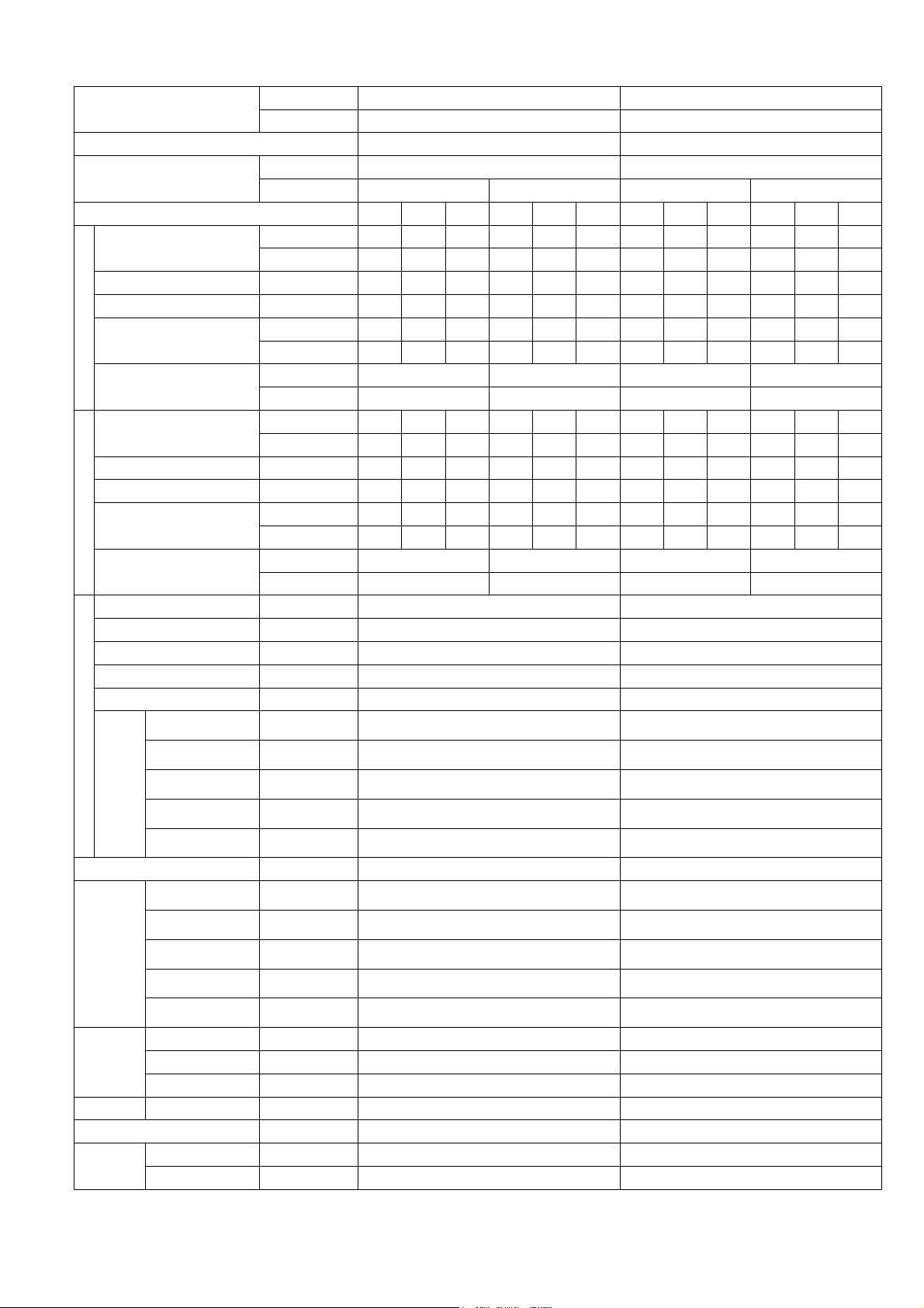
2. Specification
Model
Indoor CS-ME5RKUA CS-ME7RKUA
Outdoor CU-3E19RBU CU-3E19RBU
Performance Test Condition AHRI AHRI
Power Supply
Phase, Hz Single, 60 Single, 60
V 208 230 208 230
Min. Mid. Max. Min. Mid. Max. Min. Mid. Max. Min. Mid. Max.
Cooling
Capacity
kW 1.30 1.62 2.30 1.30 1.62 2.30 1.80 2.01 2.90 1.80 2.01 2.90
BTU/h 4400 5500 7800 4400 5500 7800 6100 6900 9900 6100 6900 9900
Running Current A - 2.3 - - 2.0 - - 2.8 - - 2.5 -
Input Power W 250 400 640 250 400 640 340 500 810 340 500 810
EER
W/W 5.20 4.05 3.59 5.20 4.05 5.20 5.29 4.02 3.58 5.29 4.02 3.58
Btu/hW 17.60 13.75 12.20 17.60 13.75 12.20 17.95 13.80 12.20 17.95 13.80 12.20
Indoor Noise (H / L)
dB-A 38 / 25 38 / 25 39 / 25 39 / 25
Power Level dB 54 / - 54 / - 55 / - 55 / -
Heating
Capacity
kW 1.20 2.61 3.20 1.20 2.61 3.20 1.20 3.21 4.10 1.20 3.21 4.10
BTU/h 4100 8900 10900 4100 8900 10900 4100 10900 14000 4100 10900 14000
Running Current A - 3.4 - - 3.0 - - 4.1 - - 3.7 -
Input Power W 300 600 960 300 600 960 300 740 1.23k 300 740 1.23k
COP
W/W 4.00 4.35 3.33 4.00 4.35 3.33 4.00 4.34 3.33 4.00 4.34 3.33
Btu/hW 13.65 14.85 11.35 13.65 14.85 11.35 13.65 14.75 11.40 13.65 14.75 11.40
Indoor Noise (H / L)
dB-A 40 / 29 40 / 29 41 / 29 41 / 29
Power Level dB 56 / - 56 / - 57 / - 57 / -
Indoor Fan
Type Cross-flow fan Cross-flow fan
Material ASG20K1 ASG20K1
Motor Type DC (8 poles) DC (8 poles)
Input Power W 47.0 - 47.0 47.0 - 47.0
Output Power W 40 40
Speed
QLo rpm
Cooling : 570
Heating : 690
Cooling : 570
Heating : 690
Lo rpm
Cooling : 660
Heating : 780
Cooling : 660
Heating : 780
Me rpm
Cooling : 820
Heating : 950
Cooling : 840
Heating : 960
Hi rpm
Cooling : 990
Heating : 1120
Cooling : 1020
Heating : 1150
SHi rpm
Cooling : 1080
Heating : 1210
Cooling : 1100
Heating : 1240
Moisture Removal L/h (Pt/h) 0.3 (0.6) 0.4 (0.8)
Indoor
Airflow
QLo m
3
/min (ft
3
/min)
Cooling : 6.00 (212)
Heating : 6.88 (243)
Cooling : 6.06 (214)
Heating : 6.95 (245)
Lo m
3
/min (ft
3
/min)
Cooling : 7.00 (247)
Heating : 7.89 (279)
Cooling : 7.06 (249)
Heating : 7.96 (281)
Me m
3
/min (ft
3
/min)
Cooling : 8.80 (311)
Heating : 9.79 (346)
Cooling : 9.08 (321)
Heating : 9.97 (352)
Hi m
3
/min (ft
3
/min)
Cooling : 10.70 (380)
Heating : 11.70 (415)
Cooling : 11.10 (390)
Heating : 12.10 (425)
SHi m
3
/min (ft
3
/min)
Cooling : 11.71 (413)
Heating : 12.70 (448)
Cooling : 12.10 (425)
Heating : 13.11 (463)
Dimension
Height (I/D) mm (inch) 290 (11-7/16) 290 (11-7/16)
Width (I/D) mm (inch) 870 (34-9/32) 870 (34-9/32)
Depth (I/D) mm (inch) 214 (8-7/16) 214 (8-7/16)
Weight Net (I/D) kg (lb) 9 (20) 9 (20)
Pipe Diameter (Liquid / Gas) mm (inch) 6.35 (1/4) / 9.52 (3/8) 6.35 (1/4) / 9.52 (3/8)
Drain Hose
Inner Diameter mm (inch) 16.7 (5/8) 16.7 (5/8)
Length mm (inch) 650 (25-5/8) 650 (25-5/8)
6
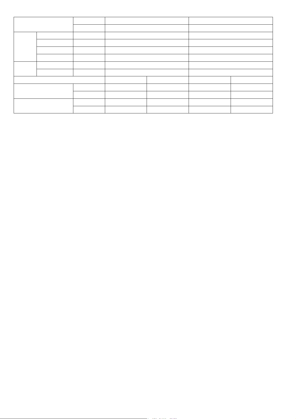
Model
Indoor CS-ME5RKUA CS-ME7RKUA
Outdoor CU-3E19RBU CU-3E19RBU
Indoor Heat
Exchanger
Fin Material Aluminium (Pre Coat) Aluminium (Pre Coat)
Fin Type Slit Fin Slit Fin
Row x Stage x FPI 2 x 15 x 21 2 x 15 x 21
Size (W x H x L) inch 1 x 12-13/32 x 24 1 x 12-13/32 x 24
Air Filter
Material Polypropelene Polypropelene
Type One-touch One-touch
DRY BULB WET BULB DRY BULB WET BULB
Indoor Operation Range
(Cooling) (°F / °C)
Maximum 89.6 / 32 73.4 / 23 89.6 / 32 73.4 / 23
Minimum 60.8 / 16 51.8 / 11 60.8 / 16 51.8 / 11
Indoor Operation Range
(Heating) (°F / °C)
Maximum 86.0 / 30 - / - 86.0 / 30 - / -
Minimum 60.8 / 16 - / - 60.8 / 16 - / -
1. Cooling capacities are based on indoor temperature of 27°C DRY BULB (80.6°F DRY BULB), 19.0°C WET BULB (66°F WET BULB) and
outdoor air temperature of 35°C DRY BULB (95°F DRY BULB), 24°C WET BULB (75.2°F WET BULB)
2. Heating capacities are based on indoor temperature of 20°C Dry Bulb (68°F Dry Bulb) and outdoor air temperature of 7°C Dry Bulb (44.6°F
Dry Bulb), 6°C Wet Bulb (42.8°F Wet Bulb)
3. Specifications are subjected to change without prior notice for further improvement.
7
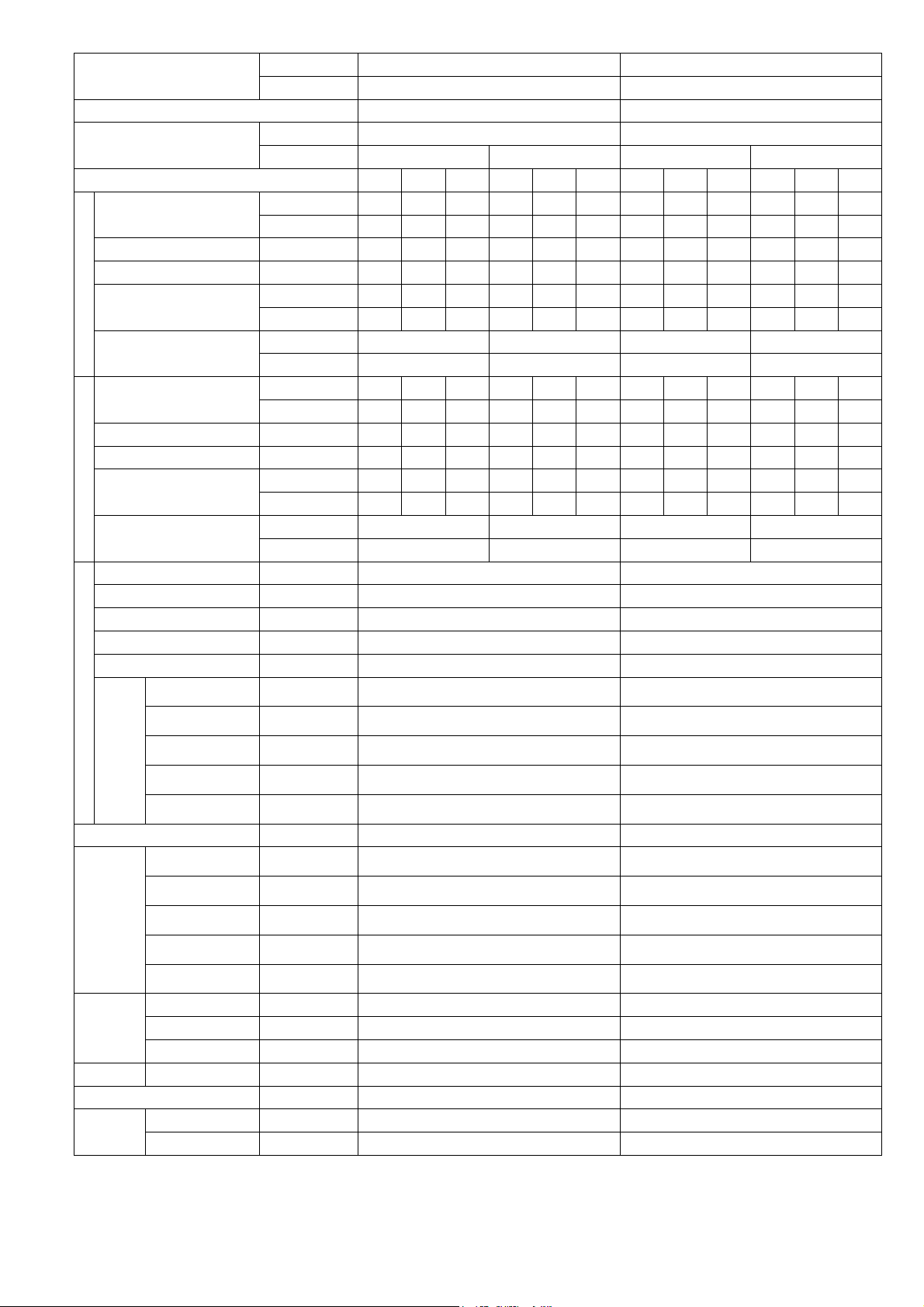
Model
Indoor CS-ME7RKUA CS-ME7RKUA
Outdoor CU-2E18NBU CU-5E36QBU
Performance Test Condition AHRI AHRI
Power Supply
Phase, Hz Single, 60 Single, 60
V 208 230 208 230
Min. Mid. Max. Min. Mid. Max. Min. Mid. Max. Min. Mid. Max.
Cooling
Capacity
kW 1.80 2.01 2.90 1.80 2.01 2.90 1.80 2.01 2.90 1.80 2.01 2.90
BTU/h 6100 6900 9900 6100 6900 4900 6100 6900 9900 6100 6900 9900
Running Current A - 2.8 - - 2.5 - - 2.8 - - 2.5 -
Input Power W 340 500 810 340 500 810 340 500 810 340 500 810
EER
W/W 5.29 4.02 3.58 5.29 4.02 3.58 5.29 4.02 3.58 5.29 4.02 3.58
Btu/hW 17.95 13.80 12.20 17.95 13.80 12.20 17.95 13.80 12.20 17.95 13.80 12.20
Indoor Noise (H / L)
dB-A 39 / 25 39 / 25 39 / 25 39 / 25
Power Level dB 55 / - 55 / - 55 / - 55 / -
Heating
Capacity
kW 1.20 3.21 4.10 1.20 3.21 4.10 1.20 3.21 4.10 1.20 3.21 4.10
BTU/h 4100 10900 14000 4100 10900 14000 4100 10900 14000 4100 10900 14000
Running Current A - 4.1 - - 3.7 - - 4.1 - - 3.27 -
Input Power W 300 740 1.23k 300 740 1.23k 300 740 1.23k 300 740 1.23k
COP
W/W 4.00 4.34 3.33 4.00 4.34 3.33 4.00 4.34 3.33 4.00 4.34 3.33
Btu/hW 13.65 14.75 11.40 13.65 14.75 11.40 13.65 14.75 11.40 13.65 14.75 11.40
Indoor Noise (H / L)
dB-A 41 / 29 41 / 29 41 / 29 41 / 29
Power Level dB 57 / - 57 / - 57 / - 57 / -
Indoor Fan
Type Cross-flow fan Cross-flow fan
Material ASG20K1 ASG20K1
Motor Type DC (8 poles) DC (8 poles)
Input Power W 47.0 - 47.0 47.0 - 47.0
Output Power W 40 40
Speed
QLo rpm
Cooling : 570
Heating : 690
Cooling : 570
Heating : 690
Lo rpm
Cooling : 660
Heating : 780
Cooling : 660
Heating : 780
Me rpm
Cooling : 840
Heating : 960
Cooling : 840
Heating : 960
Hi rpm
Cooling : 1020
Heating : 1150
Cooling : 1020
Heating : 1150
SHi rpm
Cooling : 1100
Heating : 1240
Cooling : 1100
Heating : 1240
Moisture Removal L/h (Pt/h) 0.4 (0.8) 0.4 (0.8)
Indoor
Airflow
QLo m
3
/min (ft
3
/min)
Cooling : 6.06 (214)
Heating : 6.95 (245)
Cooling : 6.06 (214)
Heating : 6.95 (245)
Lo m
3
/min (ft
3
/min)
Cooling : 7.06 (249)
Heating : 7.96 (281)
Cooling : 7.06 (249)
Heating : 7.96 (281)
Me m
3
/min (ft
3
/min)
Cooling : 9.08 (321)
Heating : 9.97 (352)
Cooling : 9.08 (321)
Heating : 9.97 (352)
Hi m
3
/min (ft
3
/min)
Cooling : 11.10 (390)
Heating : 12.10 (425)
Cooling : 11.10 (390)
Heating : 12.10 (425)
SHi m
3
/min (ft
3
/min)
Cooling : 12.10 (425)
Heating : 13.11 (463)
Cooling : 12.10 (425)
Heating : 13.11 (463)
Dimension
Height (I/D) mm (inch) 290 (11-7/16) 290 (11-7/16)
Width (I/D) mm (inch) 870 (34-9/32) 870 (34-9/32)
Depth (I/D) mm (inch) 214 (8-7/16) 214 (8-7/16)
Weight Net (I/D) kg (lb) 9 (20) 9 (20)
Pipe Diameter (Liquid / Gas) mm (inch) 6.35 (1/4) / 9.52 (3/8) 6.35 (1/4) / 9.52 (3/8)
Drain Hose
Inner Diameter mm (inch) 16.7 (5/8) 16.7 (5/8)
Length mm (inch) 650 (25-5/8) 650 (25-5/8)

8
Model
Indoor CS-ME7RKUA CS-ME7RKUA
Outdoor CU-2E18NBU CU-5E36QBU
Indoor Heat
Exchanger
Fin Material Aluminium (Pre Coat) Aluminium (Pre Coat)
Fin Type Slit Fin Slit Fin
Row x Stage x FPI 2 x 15 x 21 2 x 15 x 21
Size (W x H x L) inch 1 x 12-13/32 x 24 1 x 12-13/32 x 24
Air Filter
Material Polypropelene Polypropelene
Type One-touch One-touch
DRY BULB WET BULB DRY BULB WET BULB
Indoor Operation Range
(Cooling) (°F / °C)
Maximum 89.6 / 32 73.4 / 23 89.6 / 32 73.4 / 23
Minimum 60.8 / 16 51.8 / 11 60.8 / 16 51.8 / 11
Indoor Operation Range
(Heating) (°F / °C)
Maximum 86.0 / 30 - / - 86.0 / 30 - / -
Minimum 60.8 / 16 - / - 60.8 / 16 - / -
1. Cooling capacities are based on indoor temperature of 27°C DRY BULB (80.6°F DRY BULB), 19.0°C WET BULB (66°F WET BULB) and
outdoor air temperature of 35°C DRY BULB (95°F DRY BULB), 24°C WET BULB (75.2°F WET BULB)
2. Heating capacities are based on indoor temperature of 20°C Dry Bulb (68°F Dry Bulb) and outdoor air temperature of 7°C Dry Bulb (44.6°F
Dry Bulb), 6°C Wet Bulb (42.8°F Wet Bulb)
3. Specifications are subjected to change without prior notice for further improvement.

9
3. Features
Inverter Technology
o Wider output power range
o Energy saving
o Quick Cooling
o More precise temperature control
Environment Protection
o Non-ozone depletion substances refrigerant (R410A)
Long Installation Piping
o Long piping up to 82 feet (25 meters) for 1 room, 164 feet (50 meters) for total room
Easy to use remote control
Quality Improvement
o Random auto restart after power failure for safety restart operation
o Gas leakage protection
o Prevent compressor reverse cycle
o Inner protector to protect Compressor
o Noise prevention during soft dry operation
Operation Improvement
o Quiet mode to reduce the indoor unit operating sound
o Powerful mode to reach the desired room temperature quickly
Serviceability Improvement
o Breakdown Self Diagnosis function
10
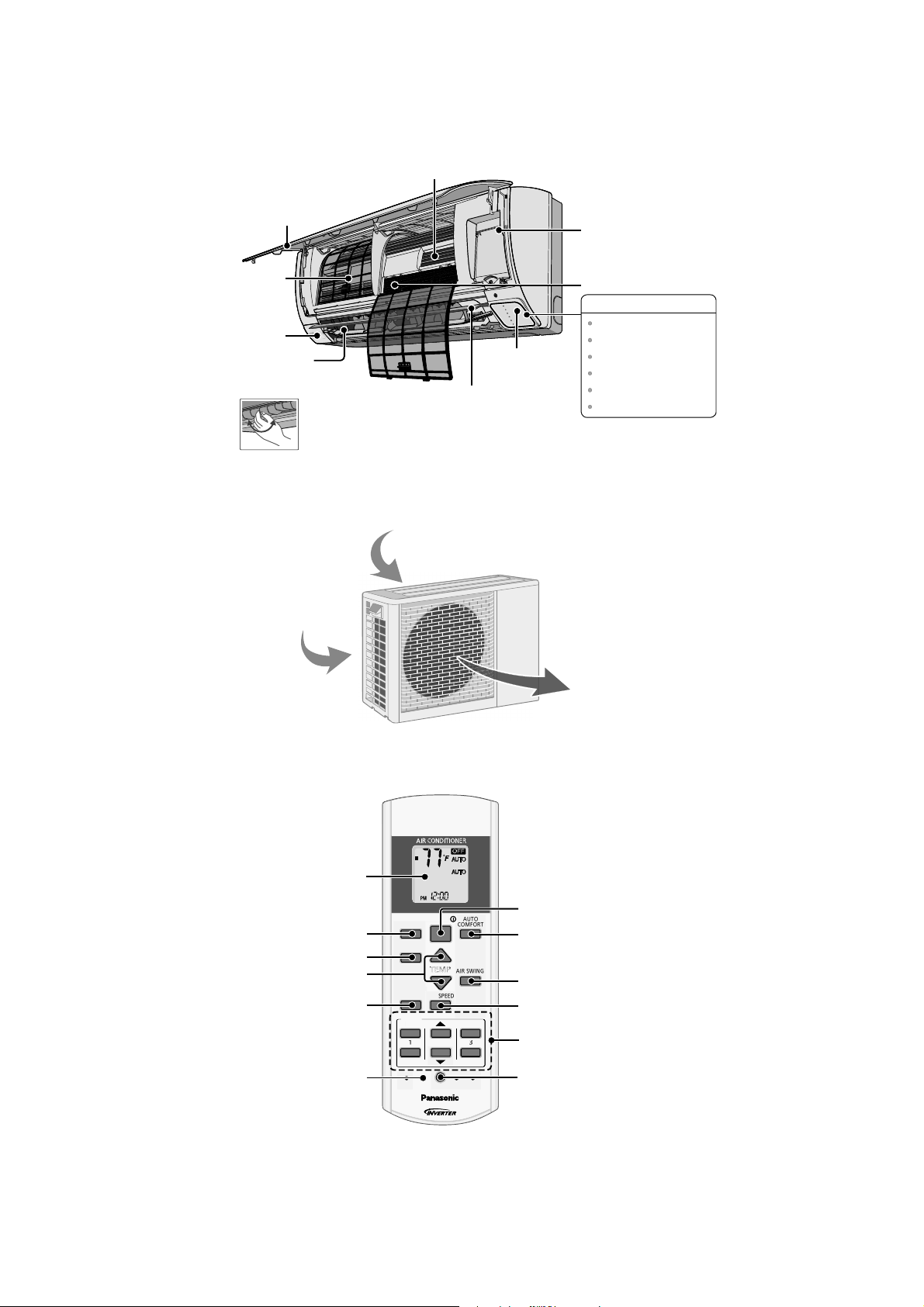
4. Location of Controls and Components
4.1 Indoor Unit
4.2 Outdoor Unit
4.3 Remote Control
P
O
W
E
R
T
I
M
E
R
E
C
O
N
A
V
I
A
U
T
O
C
O
M
F
O
R
T
P
O
W
E
R
F
U
L
Q
U
I
E
T
Horizontal Airflow
Direction Louver
• Manually adjustable.
A
l
u
m
i
n
i
u
m
Fi
n
Auto OFF/ON button
Air Purifying Filter
Human activity
sensor
Front Panel
Remote control
receiver and Indicator
INDICATOR
Vertical Airflow
Direction Louver
• Do not adjust by hand.
POWER
TIMER
ECONAVI
AUTO COMFORT
POWERFUL
QUIET
(Green)
(Orange)
(Green)
(Green)
(Orange)
(Orange)
Air Filters
Air inlet (rear)
A
ir inlet (side)
Air outlet
AUTO
COMFORT
MODE
POWERFUL/
QUIET
TEM P
OFF/ON
TIMER
SET
CANCEL
ON
OFF
1
2
3
AIR SWING
FAN SPE ED
SET CHECK CLO CK RESET
AC
RC
ECONAVI
FAN
SPEED
AIR
SW ING
AUTO
HEAT
COOL
DRY
FAN
/
TEMP
O
FF/
O
N
T
I
M
E
R
S
ET
C
AN
C
E
L
O
N
O
FF
1
2
3
C
HE
C
K
Timer setting
Clock setting
Fan speed selection
Vertical airflow
direction selection
Auto comfort operation
Remote control
display
OFF/ON
Operation mode
Temperature setting
Powerful/Sleep mode
operation
Check
Econavi operation
11
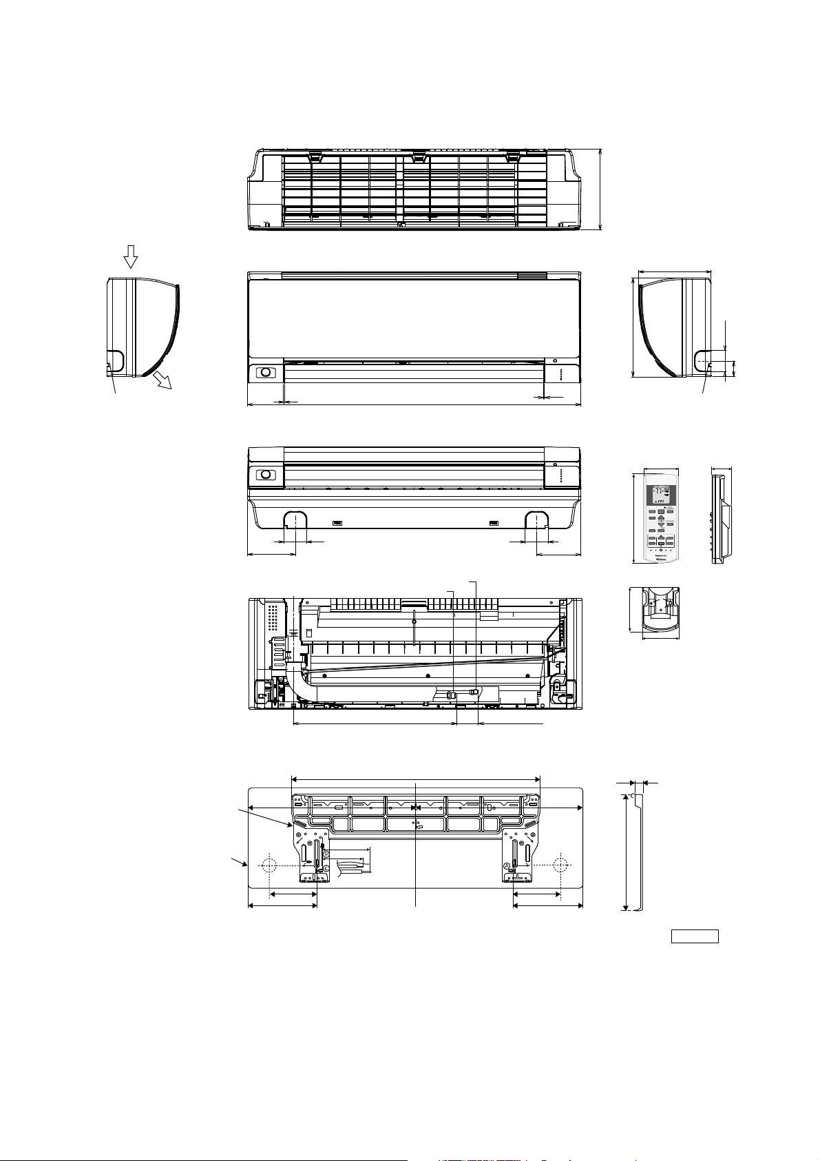
5. Dimensions
5.1 Indoor Unit
7/8
1-7/8
5-1/4
Remote control
Remote control holder
2
2-3/8
AUTO
COMFORT
MODE
POWERFUL/
QUIET
TEMP
OFF/ON
TIMER
SET
CANCEL
ON
OFF
12
3
AIR SWIN G
FAN SPEED
SET CHECK CLOC K RE SET
AC RC
ECONAVI
FAN
SPEED
AIR
SWING
AUTO
HEAT
COOL
DRY
FAN
/
T
E
M
P
O
FF/ON
TIMER
S
ET
C
AN
C
EL
O
N
O
FF
1
2
3
C
HE
C
K
5/8
10-3/8
Relative position between the indoor unit and the installation plate <Front View>
Unit: inch
29-29/64
5-1/16
3-3/4
1-11/16
9-17/32 9-17/32
5-1/16
Right
piping
hole
Left
piping
hole
Installation
plate
Indoor unit
external
dimensions
line
1717-9/32
(8-7/16)
11-7/16
2-13/32
1-49/64
8-7/16
1/32~1/16
1/32~1/16
34-9/32
4-17/32
(1-5/8~2-13/32)
16-1/8
Liquid side
Gas side
4-29/32
2-11/322-11/32
<Side View> <Side View>
<Top View>
<Front View>
<Bottom View>
<Rear View>
Air intake
direction
Air outlet
direction
Left piping
hole
Right piping
hole
12
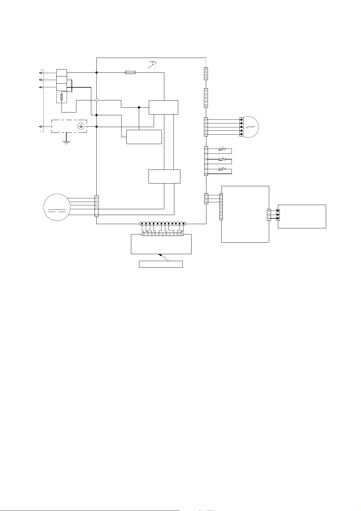
6. Wiring Connection Diagram
6.1 Indoor Unit
M
RECTIFICATION
CIRCUIT
CO MM UN IC A T IO N
CIRCUIT
GROUNDING
TERM INAL
1
W
2
3
BL
EVAPORATOR
AC303 (WH T)
AC306 (BLK)
AC304 (RED)
G301 (GRN)
FUSE301
T3.15A L250V
NO ISE FIL T E R
CIRCUIT
TEM P.
FUSE
102°C
(3A)
TO
OUTDOOR
UNIT
TERMINAL
BOARD
R
Y/G
G
AUTO SW
(SW 01)
ELECTRONIC
CONTROLLER
(MA IN )
CN–FM (WHT)
FAN MOTOR
5
6
7
1
4
BL
W
B
Y
R
REMO TE CONTRO LLER
ELECTRONIC CONTROLLER
(DISPLAY & RECEIVER)
t
t
t
CN–STM1
(WH T)
CN–RMT
(W HT)
4
1
1
BR
R
O
Y
P
5
1
5
CN–CNT
(WHT )
5
1
6
1
M
3
1
CN–MSEN S
(WH T)
CN–TH
(RED )
PIPING TEMP. SENSOR 2
(THERMISTOR)
PIPING TEMP. SENSOR 1
(THERMISTOR)
SUCTION TEM P. SEN SOR
(THERMISTOR)
UP DOWN
LOUVER MOTOR
ELECTRONIC
CONTRO LLER
(ECO SENSOR)
ELECTRONIC CONTROLLER
(COMPARATOR)
1
8
1
3
1
3
CN–SEN S1
(YLW)
CN–MSENS
(WHT )
CN-SENS1
(WH T)
W
W
W
W
W
W
REMARK S
B : BLUE P : PINK
BR : BROWN O : ORANGE
BL : BLACK Y : YELLOW
W : WHITE G : GREEN
R : RED
Y/G : YELLOW /GREEN
CN–DISP (WHT)
CN–DISP (YLW)
1
11
1
12
WWW
W
WWWWW

13
7. Electronic Circuit Diagram
7.1 Indoor Unit
BZ201
BZ
5V_
R209
47
IC201
C202
0.01u
C201
47u
R218
0
c
e
JP201R210
JP200R211
JP203R212
JP204
POWERFUL/QUIET
(orange/green)
1
3
2
LED205
R207
620
SEN201
PCB3
R216
0
R206
2.7k
R217
0
b
c
e
Q202
Q201
4.7k
10k
R213
R208
GND-A
+
1
2
3
Vout
Vcc
GND
GNDGND
45
5V_
5V_
R215
0
R204
820
R203
27k
R202
2k
R201 470
LED204
(green )
NANOE G/AUTO COMF
LED203
(green )
ECO NAVI
LED202
(orange)
TIMER
LED201
(green)
POWER
b
c
e
4.7k
10k
12V
ELECTRONIC CONTROLLER
(DISPLAY & RECEIVER)
CN–DISP (WHT)
1
11
REMOTE CONTROLLER
AUTO
COM FORT
MODE
POWE RFU L/
QUIET
TEMP
OFF/ON
TIMER
SET
CANCEL
ON
OFF
12
3
AIR SWING
FAN SPEED
SET CHECK CLOCK RESET
AC
RC
ECON AV I
FAN
SPEED
AIR
SW ING
AUTO
HEAT
COOL
DRY
FAN
/
TE MP
O
F
F
/
O
N
T
I
M
E
R
S
ET
C
AN
C
E
L
O
N
O
FF
1
2
3
C
HECK
5V_3
5V_3
6
5
2
3
4
1
7
8
R401
R402
R403
C403
IC401
IC401
5V
5V
*R74
*R75
*C41
R89
C3
0.1u
C27
1u
R61
20.0k
*R63
C25
1u
R62
15.0k
*C28
5V
12V
R46R47
VCC
9
8
16
15
14
13
12
11
10
1
2
3
4
5
6
7
GND
12V
IC03
IC03
IC03
IC03
IC03
IC03
IC03
5V12V
5V
R82
10k
R90
10k
C51
1000p
*C56 *C57
*L5*L6
C52
1000p
5V
5V
*C49
NONE
*C45
0.1u
*R54
270
*R37
10k
M
RECTIFICATION
CIRCUIT
COMMUNICATION
CIRCUIT
GROUNDING
TERMINAL
1
W
2
3
BL
EVAPORATOR
AC303 (WHT)
AC306 (BLK)
AC304 (RED)
G301 (GRN)
FUSE301
T3.15A L250V
NOISE FILTER
CIRCUIT
TEMP.
FUSE
102°C
(3A)
T
O
OUTDOOR
UNIT
TERMINAL
BOARD
R
Y/G
G
AUTO SW
(SW01)
ELECTRO NIC
CONTROLLER
(MAIN )
CN–FM (WHT)
FAN MOTOR
5
6
7
1
4
BL
W
B
Y
R
t
t
t
CN–STM1
(WHT)
CN–RMT
(WHT)
4
1
1
BR
R
O
Y
P
5
1
5
CN–CNT
(WHT)
5
1
6
1
M
3
1
CN–MSENS
(WHT)
CN–TH
(RED)
PIPING TEMP. SENSOR 2
(THERMISTOR)
PIPING TEMP. SENSOR 1
(THERMISTOR)
SUCTION TEMP. SENSOR
(THERMISTOR)
UP DOWN
LOUVER MOTOR
ELECTRONIC
CONTROLLER
(ECO SENSOR)
ELECTRONIC CONTROLLER
(COMPARATOR)
1
8
1
3
1
3
CN–SENS1
(YLW)
C
N
–
M
S
E
N
S
(
W
H
T
)
CN-SENS1
(WHT)
W
W
W
W
W
W
CN–DISP (YLW)
1
12
WWW
W
WWWW W
14
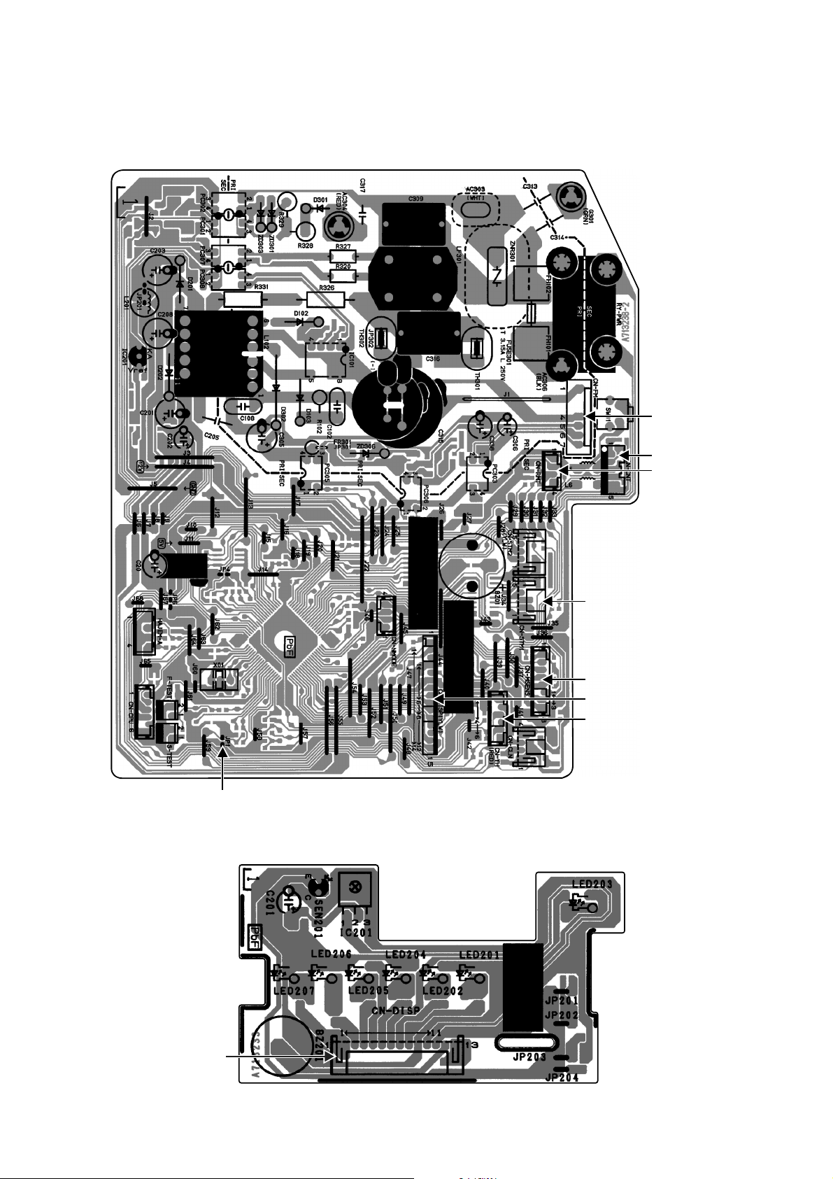
8. Printed Circuit Board
8.1 Indoor Unit
8.1.1 Main Printed Circuit Board
8.1.2 Indicator Printed Circuit Board
CN-RMT
CN-FM
CN-CNT
CN-STM1
CN-MSENS
CN-TH
J
P
1
(
R
a
n
d
o
m
Auto
R
e
start
e
n
a
b
l
e
/
d
isa
b
l
e
)
CN-DISP
CN-DISP
15
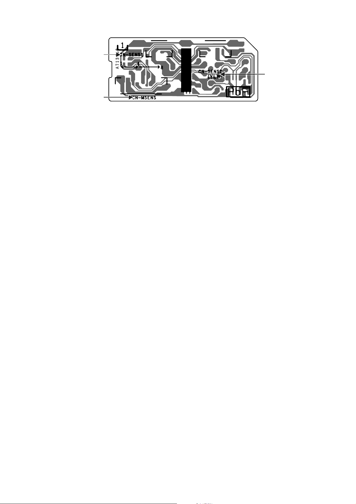
8.1.3 Comparator Printed Circuit Board
CN-SENS1
CN-SENS2
CN-MSENS
16
9. Installation Instruction
9.1 Select the Best Location
9.1.1 Indoor Unit
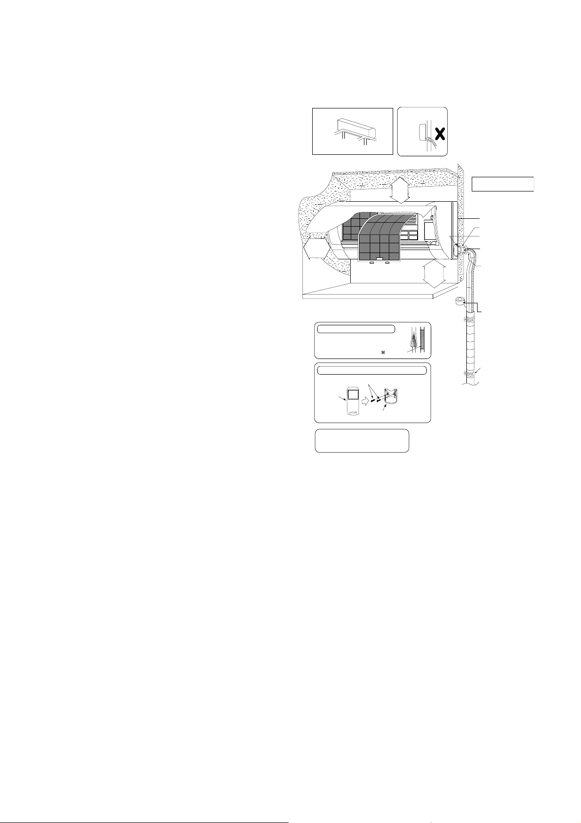
Do not install the unit in excessive oil fume area
such as kitchen, workshop and etc.
There should not be any heat source or steam
near the unit.
There should not be any obstacles blocking the air
circulation.
A place where air circulation in the room is good.
A place where drainage can be easily done.
A place where noise prevention is taken into
consideration.
Do not install the unit near the door way.
Ensure the spaces indicated by arrows from the
wall, ceiling, fence or other obstacles.
Mount with the lowest moving parts at least 8 ft
(2.4 mm) above floor or grade level.
9.1.2 Indoor/Outdoor Unit Installation
Diagram
Vinyl tape
6
Remote control holder
5
Remote
Remote control holder fixing screws
control
3
• This illustration is for explanation purposes only.
The indoor unit will actually face a diff erent way.
• Respective outdoor unit installation procedure shall
refer to instruction manual provided in the outdoor
unit packaging.
It is advisa ble to avoid more than 2 blockage
directions. For better ventilation & multiple-
outdoor installation, please consult authorized
dealer/specialist.
• Carry out insulation after
checking for gas leaks and
secure with vinyl tape.
Attaching the remote control holder to the wall
Insulation of piping connections
1
31
/
32
"
(50 mm) or
more
2
9
/
1
6
"
(
6
5
m
m
)
o
r
m
o
r
e
8
f
t
(
2
.
4
m
)
o
r
m
o
r
e
(Left and right are identical)
Floor / Grade level
Installation plate 1
Sleeve (
)
Bushing-Sleeve (
)
Bendthepipeas
closely on the wall as
possible, but be careful
that it doesn’t break.
Saddle (
)
Putty (
)
(Gum Type Sealer)
Vinyl tape (wide) (
)
• Apply after carrying
out a drainage test.
• To carry out the
drainage test,
remove the air filters
and pour water into
the heat exchanger.
Installation par ts you
should purchase ()
Attention not to bend
up drain hose
Piping direction
(Front side)
Right
Rear
Right
bottom
Left
Rear
Left bottom
Left
17
9.2 Indoor Unit
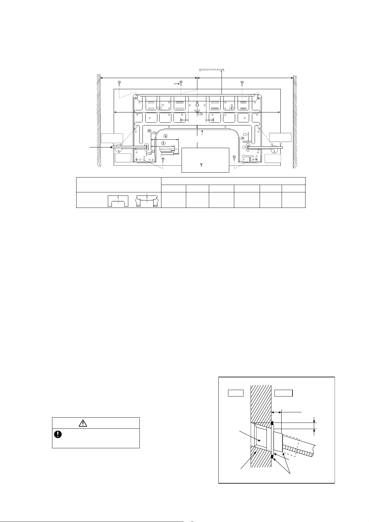
9.2.1 How to Fix Installation Plate
The mounting wall shall be strong and solid enough to prevent it from the vibration.
The center of installation plate should be at more than at right and left of the wall.
The distance from installation plate edge to ceiling should more than .
From installation plate center to unit’s left side is .
From installation plate center to unit’s right side is .
○
B : For left side piping, piping connection for liquid should be about from this line.
: For left side piping, piping connection for gas should be about from this line.
1 Mount the installation plate on the wall with 5 screws or more (at least 5 screws).
(If mounting the unit on the concrete wall, consider using anchor bolts.)
o Always mount the installation plate horizontally by aligning the marking-off line with the thread and using
a level gauge.
2 Drill the piping plate hole with ø2 3/4" (ø70 mm) hole-core drill.
o Line according to the left and right side of the installation plate. The meeting point of the extended line is
the center of the hole. Another method is by putting measuring tape at position as shown in the diagram
above. The hole center is obtained by measuring the distance namely 5 1/16" (128 mm) for left and right
hole respectively.
o Drill the piping hole at either the right or the left and the hole should be slightly slanting to the outdoor
side.
9.2.2 To Drill a Hole in the Wall and
Install a Sleeve of Piping
1 Insert the piping sleeve to the hole.
2 Fix the bushing to the sleeve.
3 Cut the sleeve until it extrudes about 19/32"
(15 mm) from the wall.
4 Finish by sealing the sleeve with putty or
caulking compound at the final stage.
Model
Dimension
123 456
ME7***
or
19
9
/
32
"
(490 mm)
3
7
/
32
"
(82 mm)
17
9
/
32
"
(439 mm)
17"
(432 mm)
1
11
/
16
"
(43 mm)
3
3
/
4
"
(95 mm)
W
all
Wall
Wall
Installation plate
1
2
screw
More than 1
More than 1
Measuring
Tape
9
17
/
32
"
(241.5 mm )
PIPE HOLE CENTER
PIPE HOLE
CENTER
DISTANCE TO
PIPE HOLE
CENTER 128 mm
5
1
/
16
"
(128 mm)
5
1
/
16
"
(128 mm)
9
17
/
32
"
(241.5 mm )
5
1
/
16
"
(128 mm)
More
tha n 2
For best strength of
INDOOR unit installation,
it is highly recomm ended
to loca te “
”at5position
as shown.
DISTANCE
TO PIPE
HOLE
CENTER
128 mm
CAUTION
When the wall is hollow, please be sure
to use the sleeve for tube assembly to
prevent dangers caused by mice biting
the connection cable.
19
/
32
" (15 mm)
Putty or caulking compound
ø2
3
/
4
"(ø70mm)
through hole
Indoor
Outdoor
Sleeve for
tube
assembly
Approx.
7
/32" -
9
/32"
(5-7 mm)
Bushing for tube
assembly
Wall
18
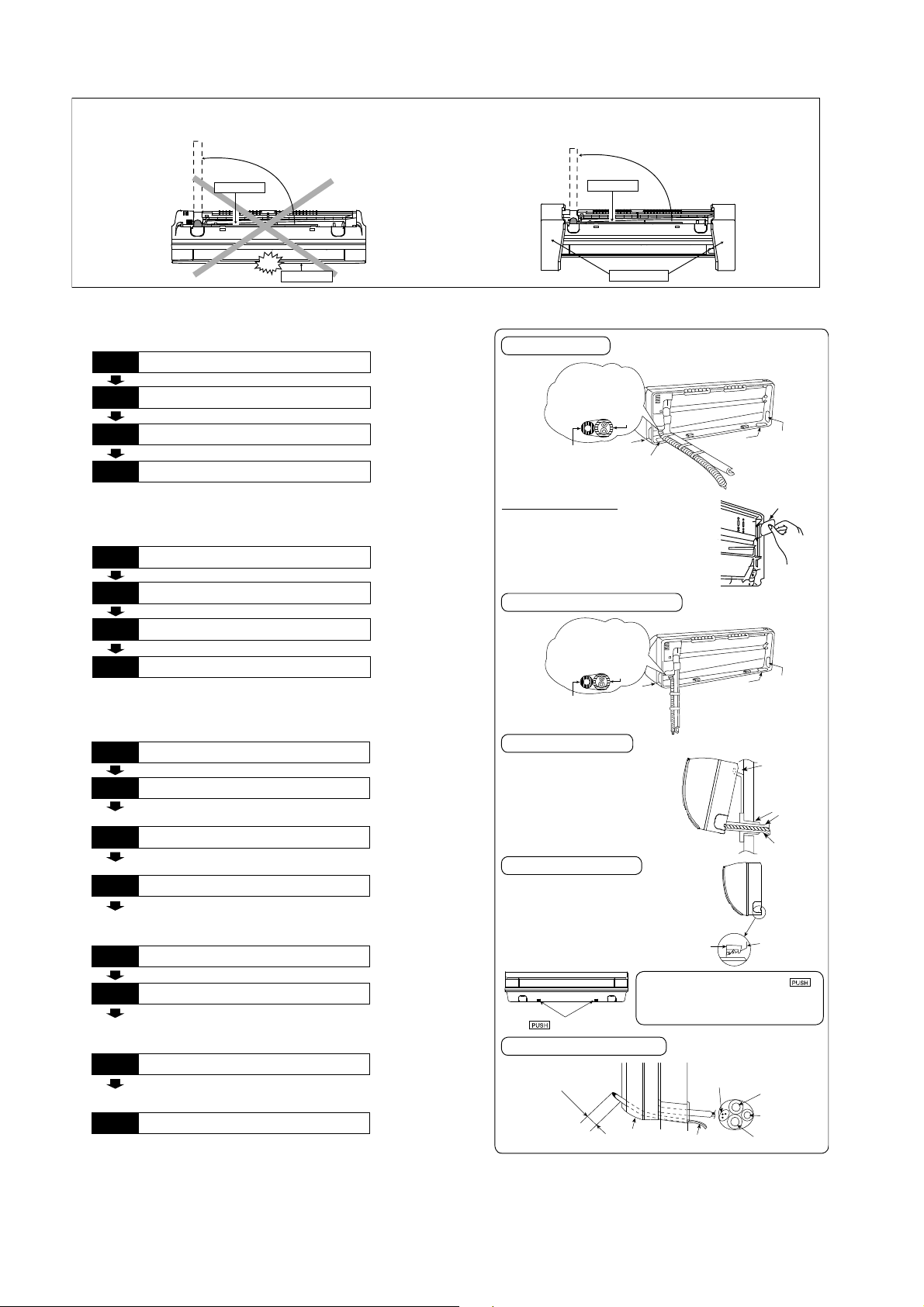
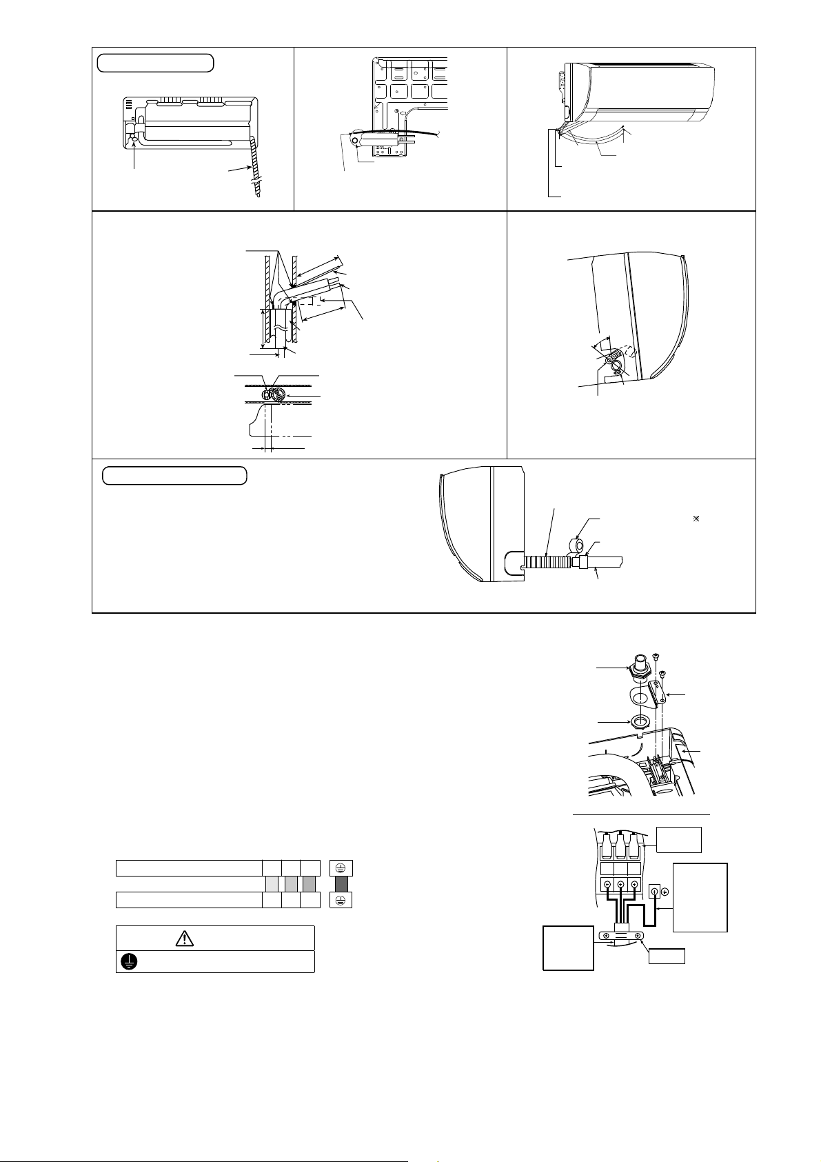
9.2.3 Indoor Unit Installation
9.2.3.1 For the right rear piping
9.2.3.2 For the right bottom piping
9.2.3.3 For the embedded piping
(This can be used for left rear piping and bottom
piping also.)
Do not turn over the unit without it’s shock absorber during pull out the piping.
It may cause intake grille damage.
Use shock absorber during pull out the piping to protect the intake grille from damage.
PUSH PUSH
Piping
Intake grille
p
u
l
l
o
u
t
t
h
e
p
i
p
i
n
g
PUSH PUSH
Piping
Shock absorber
p
u
l
l
o
u
t
t
h
e
p
i
p
i
n
g
Install the Indoor Unit
Pull out the Indoor piping
Step-2
Secure the Indoor Unit
Step-1
Step-3
Insert the connection cable
Step-4
Install the Indoor Unit
Pull out the Indoor piping
Step-2
Insert the connection cable
Step-1
Step-3
Secure the Indoor Unit
Step-4
Bend the embedded piping
• Use a spring bender or equivalent to ben d the
piping so that the piping is not crushed.
• The inside and outside connection cable can be
connected without remo ving the front grille.
• Please refer to “Connecting the piping” colum n in
outdoor unit section. (Below steps are done after
connecting the outdoor piping and gas-leakage
con firmatio n.)
• W hen determining the dimensions of the piping,
slide the unit all the w ay to the left on the installation
plate.
• Refer to the section “Cutting and flaring the piping”.
Replace the drain hose
Step-2
Pull the connection cable into Indoor Unit
Step-1
Step-3
Cut and flare the embedded piping
Step-4
Install the Indoor Unit
Step-5
Connect the piping
Step-6
• Please refer to “Insulation of piping connection”
column as m entioned in indoor/outdoor unit
installation.
Insulate and finish the piping
Step-7
Secure the Indoor Unit
Step-8
Install the indoor unit
Right Rear piping
Guide
surface
Connection cable
A
b
o
u
t
2
3
/
4
"
-
3
5
/
3
2
"
(
7
0
-
8
0
m
m
)
Connection cable
Gas side
piping
Liquid side
piping
Drain hose
Hook the indoor unit onto the upper
portion of installation plate. (Engage
the indoor unit with the upper edge
of the installation plate). Ensure the
hooks are properly s eated on the
installation plate by moving it in left
and right.
Cover for the
bottom piping
Cover for the
bottom piping
Tape it with
piping in a position as
mentioned in
Fig. below .
Cover for
the right
piping
Piping
Drain
hose
Cov er
for the
left
piping
1. Press the lower left and right side
of the unit against the installation
plate until hooks engages with their
slot (sound click).
Cover for piping
In case of the cover is cut, keep the
cover at the rear of chassis as shown
in the illustration for future
reinstallation .
(Left, right and 2 bottom covers for
piping.)
Howtokeepthecover
Cover for the
bottom piping
Tape it with piping in a
position as mentioned in
Fig. below .
Cover for
the right
piping
Piping
Drain hose
Cover for
the left
piping
Right and Right Bottom piping
Insert the connection cable
Secure the Indoor Unit
g
n
i
k
r
a
m
Drain hose
Sleev e for
piping hole
Indoor unit
Hooks at
insta lla tio n
plate
Piping
Insta lla tio n
plate
Unit’s
hook
To take out the unit, push the
marking at the bottom unit, and pull it
slightly towards you to disengage the
hooks from the unit.
19
9.2.4 Connect the Cable to the Indoor Unit
1. The inside and outside connection cable can
be connected without removing the front grille.
2. Unscrew the conduit cover and fix the conduit
connector to conduit cover with lock nut, then
secure it against chassis.
3. Connection cable between indoor unit and
outdoor unit should be UL listed or CSA
approved 4 conductor wires minimum AWG16
in accordance with local electric codes.
o Ensure the colour of wires of outdoor unit
and terminal number are the same as the
indoor's respectively
o Earth lead wire shall be Yellow/Green
(Y/G) in colour and shall be longer than
other lead wires as shown in the figure for
electrical safety in case of the slipping.
Rear view for left piping installation
Drain cap
Drain hose
•
How to pull the piping and drain hose out, in case of embedded piping.
PVC tube
for drain
hose
Indoor u nit
3
15
/
16
"(100mm)
Piping
Cable
Apply putty or
caulking m aterial
to seal the w all
opening.
Connection
cable
Piping
M
o
r
e
t
h
a
n
18
1
/
2
"
(
4
70
m
m
)
M
o
r
e
t
h
a
n
3
7
1
3
/
3
2
"
(
9
5
0
m
m
)
PVC tube (VP-65) for piping
and connection cable
PVC tube for drain hose (VP-30)
PVC tube for
drain hose (VP-20)
More than 27
9
/
16
"
(700 mm)
•
In case of left piping how to insert the connection
cable and drain hose.
Cable
4
5
°
Drain
hose
Piping
Drain hose
from m ain unit
(For the right piping, follow the same procedure)
Sleeve for p iping h ole
Drain hose
Piping
Connection
cable
More than 37
13
/
32
"(950mm)
Replace the drain hose
Indoor unit
drain hose
3/4" (20 mm) nominal PVC pipe
- Install incline downward more than 1°
- Apply PVC glue at the join.
Drain hose adapter
8
Close join by V inyl Tape ( )
•
Join indoor dr ain hose to 3/4" (20 m m ) nomina l PVC pipe size
by using drain hose adapter
8
when necessary.
Drain hose adapter
8
usage
Remarks :
Make sure indoo r unit drain ho se & 3/4" (20 m m) nom inal P VC pipe
are fully inserted to drain hose adapter
8
.
Adjust the piping slightly downwards.
Drain hose
Connection cable
Terminals on the indoor unit 1 2 3
Colour of wires (connection cable)
Terminals on the outdoor unit 1 2 3
WARNING
This equipment must be properly earthed.
123
Earth Wire
longer than
others AC
wires for
safety
reason
Term i na l
Board
Holder
Indoor and
outdoor
connection
cable
Chassis
Conduit
Connector
Conduit
Cover
Lock Nut
Rear Side of Indoor Unit
20
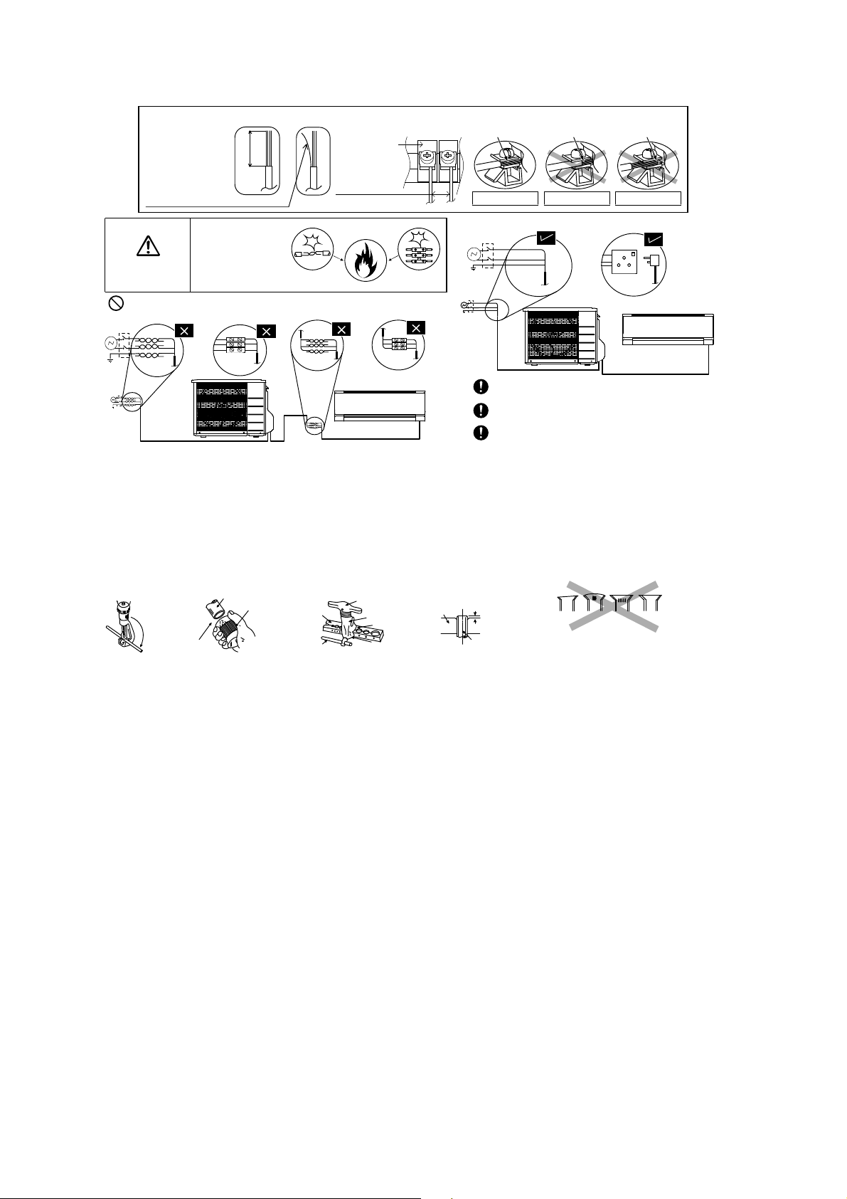
9.2.5 Wiring Stripping and connecting requirement
9.2.5.1 Cutting and flaring the piping
1 Please cut using pipe cutter and then remove the burrs.
2 Remove the burrs by using reamer. If burrs is not removed, gas leakage may be caused.
Turn the piping end down to avoid the metal powder entering the pipe.
3 Please make flare after inserting the flare nut onto the copper pipes.
WARNING
RISK OF FIRE
JOINING OF WIRES
MAY CAUSE
OVERHEA TING
AND FIRE.
OR
OR
OR
Wire stripping
No loose strand
when inserted
Conductor
fully inserted
Conductor
over inserted
Conductor not
fully inserted
ACCEPT PROHIBITED PROHIBITED
Use complete wire without joining.
Use approved socket and plug with earth pin.
Wire connection in this area must follow to
national wiring rules.
Do not joint wires
13/32" ± 1/16"
(10±1 mm)
Indoor/outdoor
connection
terminal board
7
/
32
"
(5 mm)
or more
(gap between wires)
1
.Tocut
3. To flare
Inclined Surface
damaged
Cracked Uneven
thickness
Bar
Handle
Core
Yo k e
Clamp handle
Bar
0–
1
/
32
"
(0-0.5 mm)
When properly flared, the internal surface of the
flare will evenly shine and be of even thickness.
Since the flare part comes into contact with the
connections, carefully check the flare finish.
I
m
p
r
o
p
e
r
fl
a
r
i
n
g
Copper
pipe
Reamer
2. To remove burrs
Point down
Pipe
Red arrow mark
21
10. Operation Control
10.1 Basic Function
Inverter control, which equipped with a microcomputer in determining the most suitable operation mode as time
passes, automatically adjusts output power for maximum comfort always. In order to achieve the suitable operation
mode, the microcomputer maintains the set temperature by measuring the temperature of the environment and
performing temperature shifting. The compressor at outdoor unit is operating following the frequency instructed by
the microcomputer at indoor unit that judging the condition according to internal setting temperature and intake air
temperature.
10.1.1 Internal Setting Temperature
Once the operation starts, remote control setting temperature will be taken as base value for temperature shifting
processes. These shifting processes are depending on the air conditioner settings and the operation environment.
The final shifted value will be used as internal setting temperature and it is updated continuously whenever the
electrical power is supplied to the unit.
10.2 Cooling operation
10.2.1 Thermostat control
Capability supply to indoor unit is OFF (Expansion valve closed) when Intake Air Temperature - Internal setting
temperature < -3.6°F.
Capability resume supply to indoor unit after waiting for 3 minutes, if the Intake Air temperature - Internal setting
temperature > Capability supply OFF point.
10.3 Soft Dry Operation
10.3.1 Thermostat control
Capability supply to indoor unit is OFF (Expansion valve closed) when Intake Air Temperature - Internal setting
temperature < -5.4°F.
Capability resume to indoor unit after waiting for 3 minutes, if the Intake Air temperature - Internal setting
temperature > Capability supply OFF point.
10.4 Heating Operation
10.4.1 Thermostat control
Capability supply to indoor unit is OFF (Expansion valve closed) when Intake Air Temperature - Internal setting
temperature > 1.8°F.
During this condition, the indoor fan is stopped if compressor is ON.
Capability resume supply to indoor unit after waiting for 3 minutes, if the Intake Air Temperature - Internal setting
temperature < Capability supply OFF point.
Remote Control Setting Temperature
60.8°F - 86°F
Setting Temperature Limit Checking
(Min: 60.8°F; Max 91.4°F)
Auto Operation Mode Shifting
Indoor Air Temperature Shifting
Outdoor Air Temperature Shifting
Powerful Mode Shifting
Internal Setting Temperature
22
10.4.2 Temperature Sampling Control
Temperature sampling is controlled by outdoor unit where room temperature for all power supply ON indoor unit
could be obtained.
When capability supply to the indoor unit is OFF and the compressor is ON during heating operation, the indoor
fan motor is stopped. During this condition, 15 seconds after sampling signal from outdoor unit is received, the
indoor fan start operation at low fan speed.
However, within first 4 minutes of capability stopped supply to the indoor unit, even sampling signal is received,
the sampling control is cancelled.
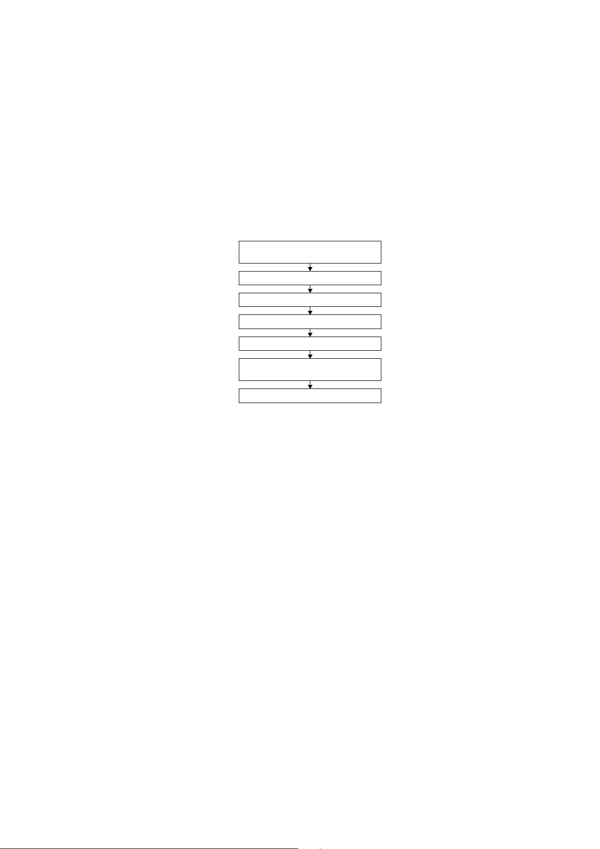
10.5 Automatic Operation
This mode can be set using remote control and the operation is decided by remote control setting temperature,
remote control operation mode, indoor intake and outdoor air temperature.
During operation mode judgment, indoor fan motor (with speed of -Lo) and outdoor fan motor are running for
30 seconds to detect the indoor intake and outdoor air temperature. The operation mode is decided based on
below chart.
10.6 Indoor Fan Speed Control
Indoor Fan Speed can be set using remote control.
10.6.1 Fan Speed Rotation Chart
ME5RKUA ME7RKUA
Mode Fan Tap Application rpm rpm
COOL
SHi Pwr Me+ 1080 1110
Hi Fc, RC 990 1020
Me+ RC 900 930
Me RC 820 840
Me- RC 740 750
Lo Fcmin, RC 660 660
Lo- QuietLo 570 570
SLo Dry 550 550
SSLo Auto Cut 540 540
ME5RKUA ME7RKUA
Mode Fan Tap Application rpm rpm
HEAT
SSHi Pwr Me+ 1210 1240
SHi Fh, RC 1120 1150
Me+ RC 1030 1050
Me RC 950 960
Me- RC 860 870
Lo Fhmin, RC 780 780
Lo- QuietLo 690 690
SLo Thermo Off, Hot start 580 580
SSLo Thermo Off 570 570
Indoor intake air
temperature (F)
Heating Mode
Soft Dry Mode
Cooling Mode
Remote Control
setting temperature
T1
T2
T3
96.8
60.8
66.255.4 69.8 73.4 77
Outdoor air
temperature (F)
23
10.7 Indoor Fan Motor Operation
10.7.1 Residual Heat Removal Control
To prevent high pressure at indoor unit, when heating mode thermostat-off condition or power supply OFF,
indoor fan continue to operate at controlled fan speed for maximum 30 seconds then stop.
10.7.2 Basic Rotation Speed (rpm)
Manual Fan Speed
[Cooling, Dry]
o Fan motor’s number of rotation is determined according to remote control setting.
Remote control ○ ○ ○ ○ ○
Tab Hi Me+ Me Me- Lo
[Heating]
o Fan motor’s number of rotation is determined according to remote control setting.
Remote control ○ ○ ○ ○ ○
Tab Shi Me+ Me Me- Lo
Auto Fan Speed
[Cooling, Dry]
o According to room temperature and setting temperature, indoor fan speed is determined automatically.
o The indoor fan will operate according to pattern below.
o During operation, indoor fan motor may stop due to odor prevention.
[Heating]
o According to indoor pipe temperature, automatic heating fan speed is determined as follows.
Feedback control
o Immediately after the fan motor started, feedback control is performed once every second.
o During fan motor on, if fan motor feedback ≥ 2550 rpm or < 50 rpm continue for 10 seconds, then fan motor
error counter increase, fan motor is then stop and restart. If the fan motor counter becomes 7 times, then
H19 - fan motor error is detected. Operation stops and cannot on back.
abc def gh
[1 pattern : 10 s]
ab
H
igher
F
an
S
peed
M
edium
Lower
RPM Increased
RPM Maintain
RPM Reduced
OFF
Indoor Pipe Temp.
95
o
C
102.2
o
F
60.8
o
F
66.2
o
F
24
10.8 Outdoor Fan Motor Operation
Outdoor fan motor is operated with fan speed number of rotation. It starts when compressor starts operation and it
stops 30 seconds after compressor stops operation.
ON ON
Compressor OFF
ON Fan Speed ON
Outdoor Fan 30 sec OFF
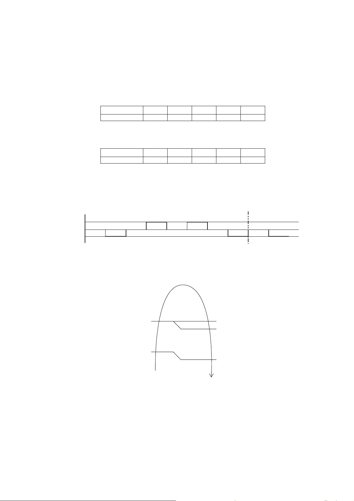
10.9 Airflow Direction
There are two types of airflow, vertical airflow (directed by horizontal vane) and horizontal airflow (directed by
vertical vanes).
Control of airflow direction can be automatic (angles of direction is determined by operation mode, heat
exchanger temperature and intake air temperature) and manual (angles of direction can be adjusted using
remote control).
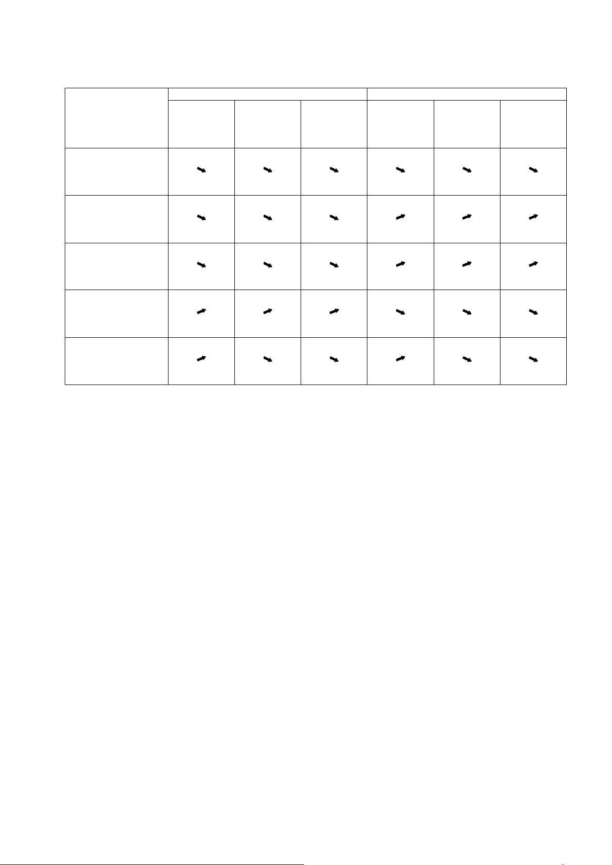
10.9.1 Vertical Airflow
Operation Mode Airflow Direction
Vane angle (°)
1 2 3 4 5
Heating
Auto with Heat Exchanger
Temperature
A 20
B 57
C 32
Manual 20 32 45 57 68
Cooling
Auto 20 ~ 45
Manual 20 26 32 37 45
Soft Dry
Auto 20 ~ 45
Manual 20 26 32 37 45
Automatic vertical airflow direction can be set using remote control; the vane swings up and down within the
angles as stated above. For heating mode operation, the angle of the vane depends on the indoor heat
exchanger temperature as Figure 1 below. When the air conditioner is stopped using remote control, the vane
will shift to close position.
Manual vertical airflow direction can be set using remote control; the angles of the vane are as stated above and
the positions of the vane are as Figure 2 below. When the air conditioner is stopped using remote control, the
vane will shift to close position.
10.9.2 Horizontal Airflow
The horizontal airflow direction louvers can be adjusted manually by hand.
140°
Close position
0
°
122°F
86°F
96.8°F
1
36.4°F
C
B
A
Indoor Heat Exchanger
Temperature
1
2
3
4
5
Side View
Figure 2Figure 1

25
10.10 Quiet Operation (Cooling Mode/Cooling Area of Dry Mode)
Purpose
o To provide quiet cooling operation compare to normal operation.
Control condition
o Quiet operation start condition
When “Quiet” button at remote control is pressed.
Quiet LED illuminates.
o Quiet operation stop condition
When one of the following conditions is satisfied, quiet operation stops:
POWERFUL/QUIET button is pressed.
Stop by OFF/ON button.
OFF Timer activates.
POWERFUL/QUIET button is pressed again.
When quiet operation is stopped, operation is shifted to normal operation with previous setting.
When fan speed is changed, quiet operation is shifted to quiet operation of the new fan speed.
When operation mode is changed, quiet operation is shifted to quiet operation of the new mode.
During quiet operation, if ON timer activates, quiet operation maintains.
After off, when on back, quiet operation is not memorised.
Control contents
o Auto fan speed is change from normal setting to quiet setting of respective fan speed. This is to reduce
sound of Hi, Me, Lo for 3dB.
o Manual fan speed for quiet operation is -1 step from setting fan speed.
10.11 Quiet Operation (Heating)
Purpose
o To provide quiet heating operation compare to normal operation.
Control condition
o Quiet operation start condition
When “POWERFUL/QUIET” button at remote control is pressed.
Quiet LED illuminates.
o Quiet operation stop condition
When one of the following conditions is satisfied, quiet operation stops:
Stop by OFF/ON button.
Timer “off” activates.
POWERFUL/QUIET button is pressed again.
When quiet operation is stopped, operation is shifted to normal operation with previous setting.
When fan speed is changed, quiet operation is shifted to quiet operation of the new fan speed.
When operation mode is changed, quiet operation is shifted to quiet operation of the new mode.
During quiet operation, if timer “on” activates, quiet operation maintains.
After off, when on back, quiet operation is not memorised.
Control contents
o Fan speed auto
Indoor FM RPM depends on pipe temperature sensor of indoor heat exchanger. Auto fan speed is
changed from normal setting to quiet setting of respective fan speed. This is to reduce sound of Hi, Me,
Lo for 3dB.
o Fan speed manual
Manual fan speed for quiet operation is -1 step from setting fan speed.
10.12 Powerful Mode Operation
When the power mode is selected, the internal setting temperature will shift lower up to 7.2F for Cooling/Soft
Dry or higher up to 10.8°F for heating than remote control setting temperature, the powerful operation continue
until user cancel the Powerful operation by pressing powerful button again.
26
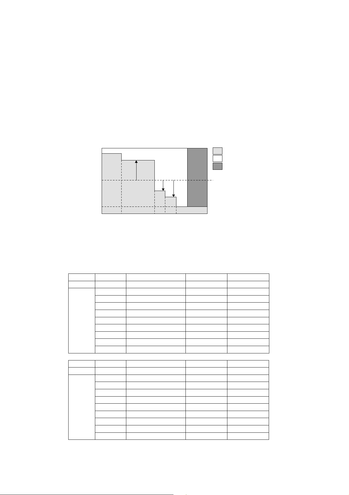
10.13 Timer Control
10.13.1 ON Timer Control
ON Timer can be set using remote control, where the unit with timer set will start operation earlier than the setting
time. This is to provide a comfortable environment when reaching the set ON time.
60 minutes before the set ON time, indoor (at fan speed of Lo-) and outdoor fan motor start operation for
30 seconds to determine the indoor intake air temperature and outdoor air temperature in order to judge the
operation starting time.
From the above judgment, the decided operation will start operation earlier than the set time as shown below.
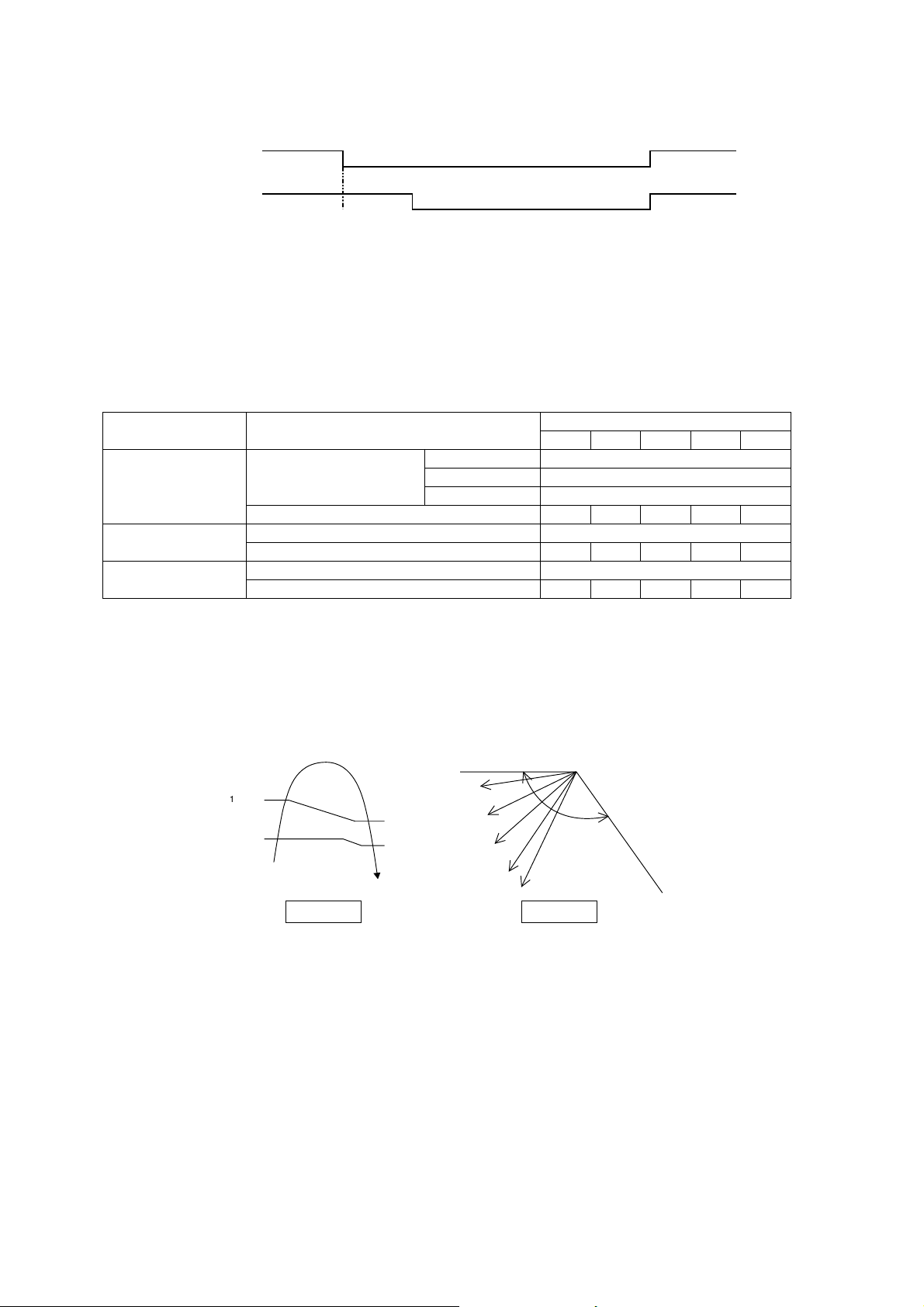
10.13.2 OFF Timer Control
OFF Timer can be set using remote control, the unit with timer set will stop at set time.
10.14 Auto Restart Control
When the power supply is cut off during the operation of air conditioner, the compressor will re-operate between
three to four minutes (10 patterns to be selected randomly) after power resume.
During multi split connection, Indoor unit will resume previous mode, include unit standby mode.
10.15 Indication Panel
LED POWER TIMER QUIET POWERFUL AUTO COMFORT ECONAVI
Color Green Orange Orange Orange Green Green
Light ON Operation ON Timer Setting ON Quiet Mode ON Powerful Mode ON Auto Comfort ON Econavi Mode ON
Light OFF Operation OFF Timer Setting OFF Quiet Mode OFF Powerful Mode OFF Auto Comfort OFF Econavi Mode OFF
Note:
If POWER LED is blinking (0.5 second ON, 0.5 second OFF), the possible operation of the unit are during Indoor
Residual Heat Removal, Hot Start, during Deice operation, operation mode judgment, or ON timer sampling.
If POWER LED is blinking (2.5 seconds ON, 0.5 second OFF), the unit is in standby mode.
If TIMER LED is blinking, there is an abnormality operation occurs.
In
d
oo
r
int
a
k
e
a
i
r
temperature (
o
F)
Outdoor air
temperature (
o
F)
86
86 95
Cooling/Soft Dry
(
o
F)
10 min
15 min
5min
77
In
d
oo
r
int
a
k
e
a
i
r
temperature (
o
F)
Outdoor air
temperature (
o
F)
59
32 41
Heating
(
o
F)
30 min
25 min
35 min
41
27
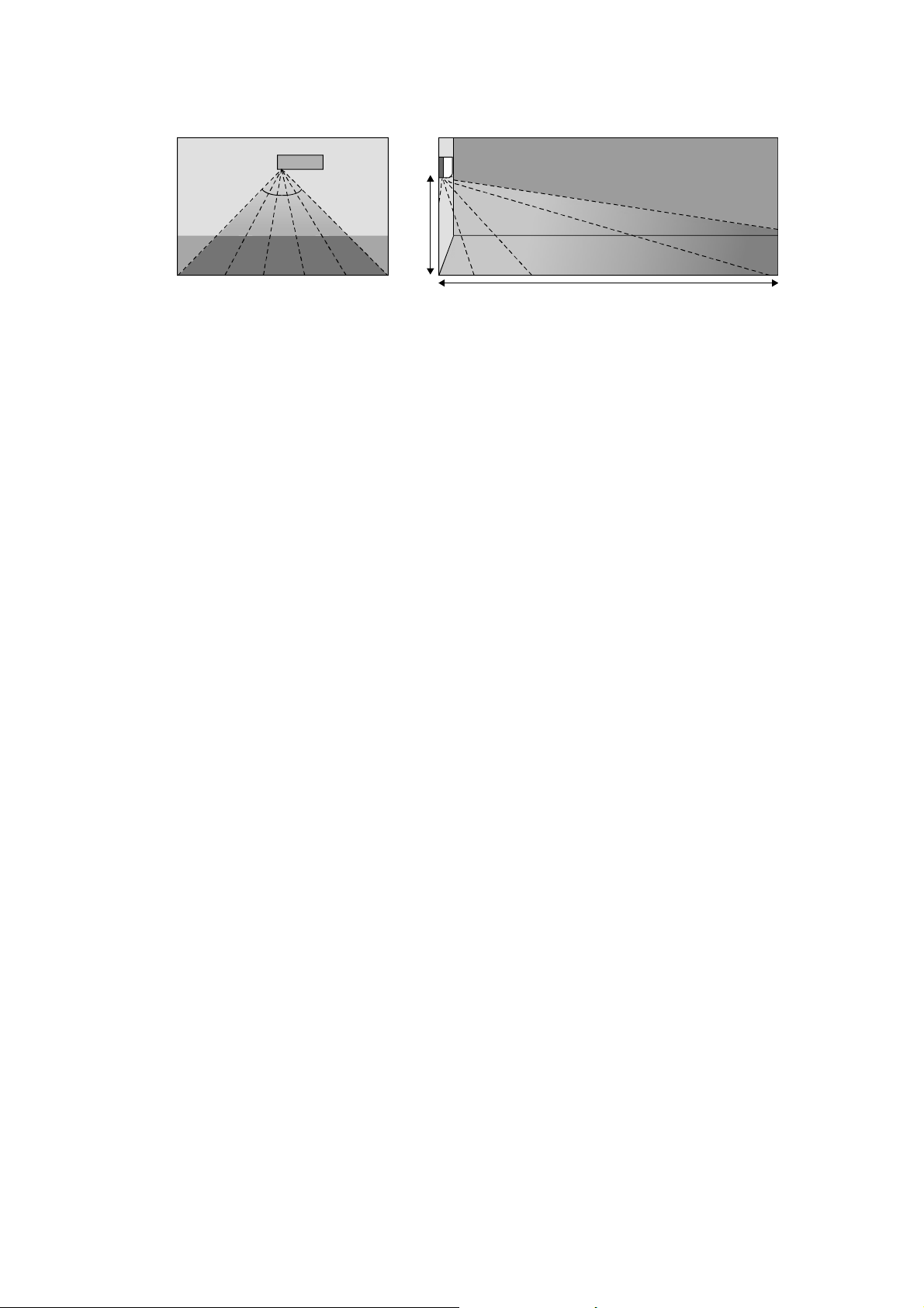
10.16 ECONAVI and AUTO COMFORT Operation
A Pyoelectric infrared sensor is used to detect injection strength variation of infrared at setting area to determine
the presence or absence of human and its activity level. Human detection area is shown in figure below:
ECONAVI and AUTO COMFORT operation – Human presence/absence detection outlined flow
Process infrared sensor output signal
Human detection (movement) every 3 seconds.
▼
Human detection records
Records human detection (movement) result for 30 seconds and determine its activity level i.e. Hi/Lo.
▼
Presence / absence detection
Compares current and previous human detection result every 30 seconds to determine the presence
or absence of human.
▼
Presence / absence determination
Based on human presence / absence detection, if human presence detection showed within
30 minutes, it is recognised that human is present. If human absence detection showed continuously
for more than 30 minutes, it is recognised that no human is present.
ECONAVI and AUTO COMFORT Sensor abnormality detection
1. Connector pulled out (disconnected), Wire cut Abnormality (Fix Output at Hi)
a. Abnormal judgment start condition.
Start from ECONAVI and AUTO COMFORT Sensor power ON, and end after 30 seconds.
b. Control content.
Judge ECONAVI and AUTO COMFORT Sensor power level every 100ms.
c. Abnormal Judgment condition.
When ECONAVI and AUTO COMFORT Sensor has continues for 25 seconds Hi level.
2. Circuit Abnormal (Fix Output Lo)
a. Abnormal judgment start condition.
After ECONAVI and AUTO COMFORT Sensor unit power ON, and after pressed 70 seconds.
b. Control content.
Judge ECONAVI and AUTO COMFORT Sensor power level every 100ms.
c. Abnormal Judgment condition.
When ECONAVI and AUTO COMFORT Sensor has continues at Lo level for 25 seconds.
3. Abnormal treatment
Any one of the above self-diagnosis result is abnormal
Abnormal counter +1 and ECONAVI and AUTO COMFORT Sensor power supply OFF.
After ECONAVI and AUTO COMFORT Sensor unit power is OFF for 5 seconds, Retry the ECONAVI and
AUTO COMFORT operation.
When Abnormal counter reach 4 counts, ECONAVI and AUTO COMFORT sensor abnormality is
confirmed.
(Abnormal counter is cleared when sensor power ON and maintain normal for 120 seconds and above or
Clear Abnormal counter by power reset)
Save ECONAVI and AUTO COMFORT Sensor Abnormality H59 (no Timer LED blinking).
ECONAVI & AUTO COMFORT Sensor operation OFF, but ECONAVI and AUTO COMFORT LED
maintain ON.
The unit still operate as normal.
Sensor error counter can be cleared only after power supply reset or AC Reset button on the remote
control is pressed.
Top Vi ew
90°
Angle of detection
Area of detection
7m
2m
28
ECONAVI and AUTO COMFORT Demo Mode
To enable ECO DEMO mode, during unit is OFF (power standby):
To disable ECO Demo MODE:
Transmit ECO Demo signal again.
Control details:
During ECONAVI and AUTO COMFORT Demo mode, operation LED ON and horizontal vane will set to Auto
Swing.
When Hi activity judge, Fan speed change to Hi Fan and ECONAVI and AUTO COMFORT LED ON.
When Lo activity judge, Fan speed change to Lo Fan and ECONAVI and AUTO COMFORT LED OFF.
No setting temperature adjustment.
During ECONAVI and AUTO COMFORT operation, the internal setting temperature and fan speed are adjusted
in order to provide comfort and energy saving.
ECONAVI Start condition.
Press ECONAVI button.
ECONAVI Stop condition.
Press ECONAVI button again.
OFF Timer activates.
Press OFF/ON button to turn off the air conditioner.
Press AUTO OFF/ON button to turn off the air conditioner.
Press POWERFUL/QUIET button.
AUTO COMFORT Start condition.
Press AUTO COMFORT button.
AUTO COMFORT Stop condition.
Press AUTO COMFORT button again.
OFF Timer activates.
Press OFF/ON button to turn off the air conditioner.
Press AUTO OFF/ON button to turn off the air conditioner.
Press POWERFUL/QUIET button.
ECONAVI and AUTO COMFORT operation could ON when any of the following conditions is fulfilled:
During forced cooling or forced heating operation.
Power Failure
ECONAVI and AUTO COMFORT operation will be resuming after recovered from power failure.
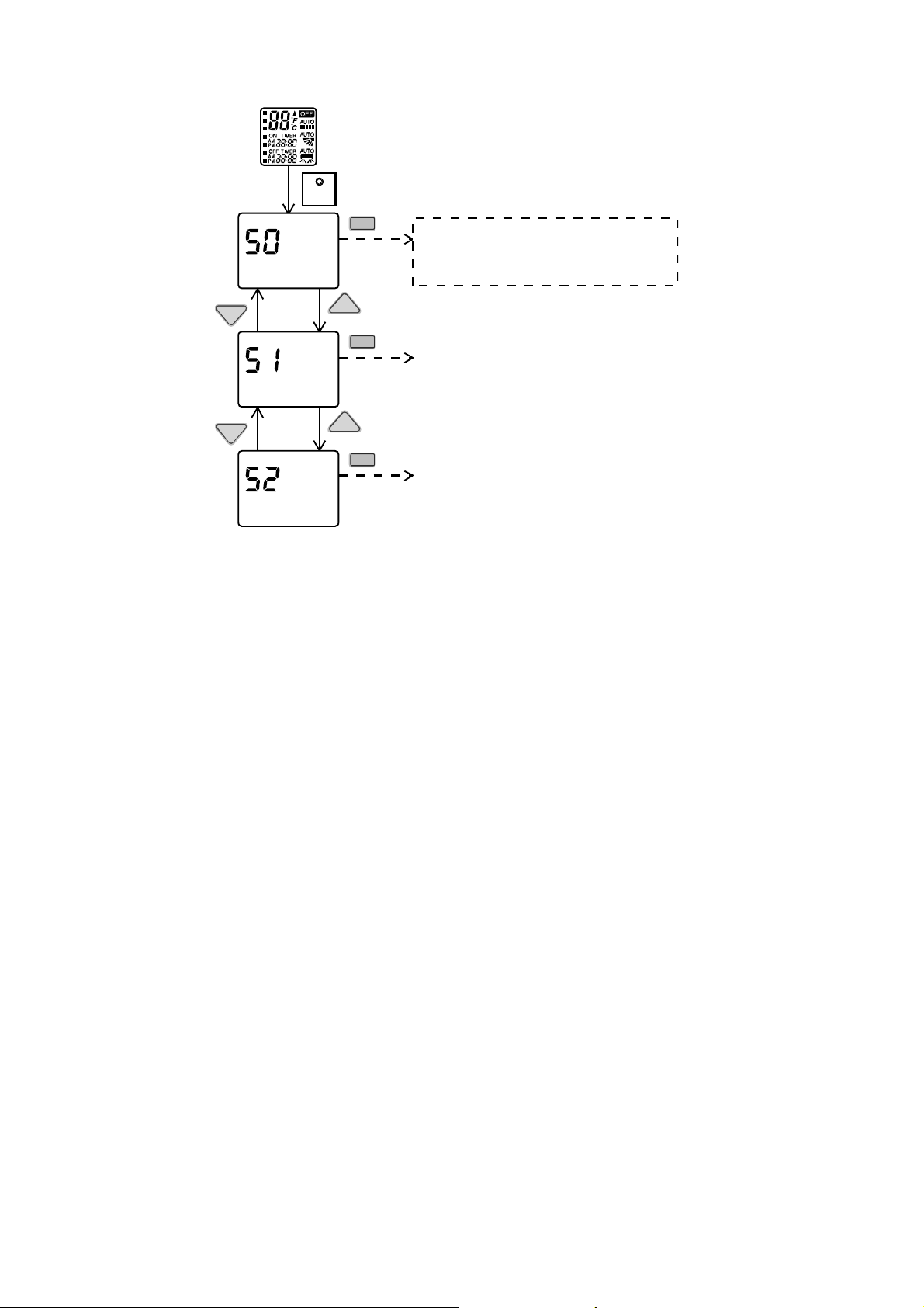
SET
Press continously for 5s
Remote control normal mode
TEM P
TEMP
SET
TEM P
TEMP
SET
SET
Transmit ECO demo code
and after 30 seconds return to normal
mode.
Transmit sunlight sensor check code
and after 30 seconds return to normal
mode.
Transmit check code
and after 30 seconds return to normal
mode.
29
Timer Operation
When unit is turn on by ON Timer and ECONAVI and AUTO COMFORT operation is ON during previous
operation before OFF, ECONAVI and AUTO COMFORT operation will not be ON automatically.
When unit is turn on by ON Timer and ECONAVI and AUTO COMFORT operation is OFF during
previous operation before OFF, ECONAVI and AUTO COMFORT operation will not be ON automatically.
Other Information
ECONAVI and AUTO COMFORT, Powerful, Quiet and Mild Dry Cooling cannot be operated at the same
time.
ECONAVI and AUTO COMFORT sensor initialized time is 70 seconds from power supplied to ECONAVI
and AUTO COMFORT sensor, or 70 seconds from the operation start.
Setting Temperature and Fan Speed Shift
Mono Sensor
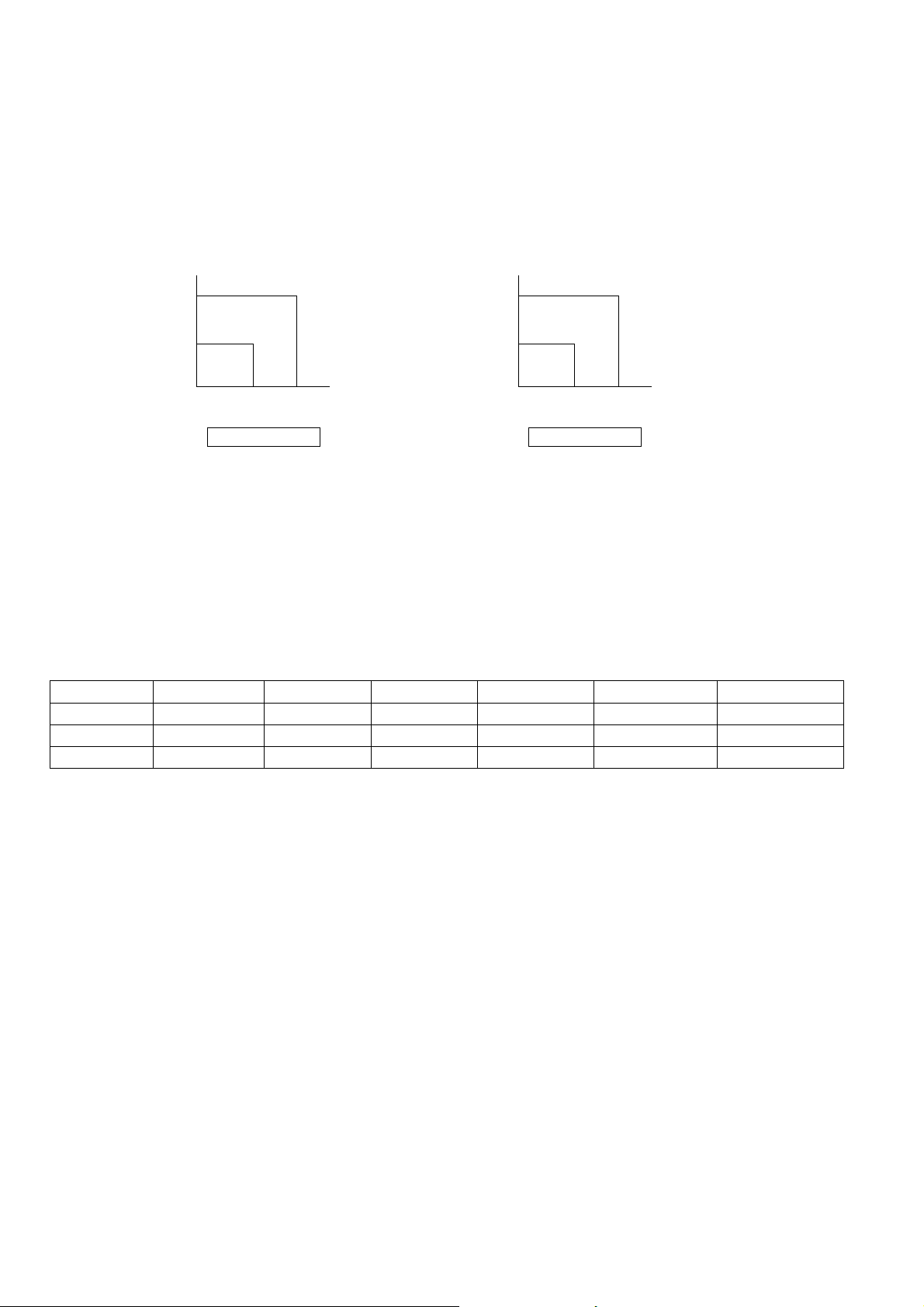
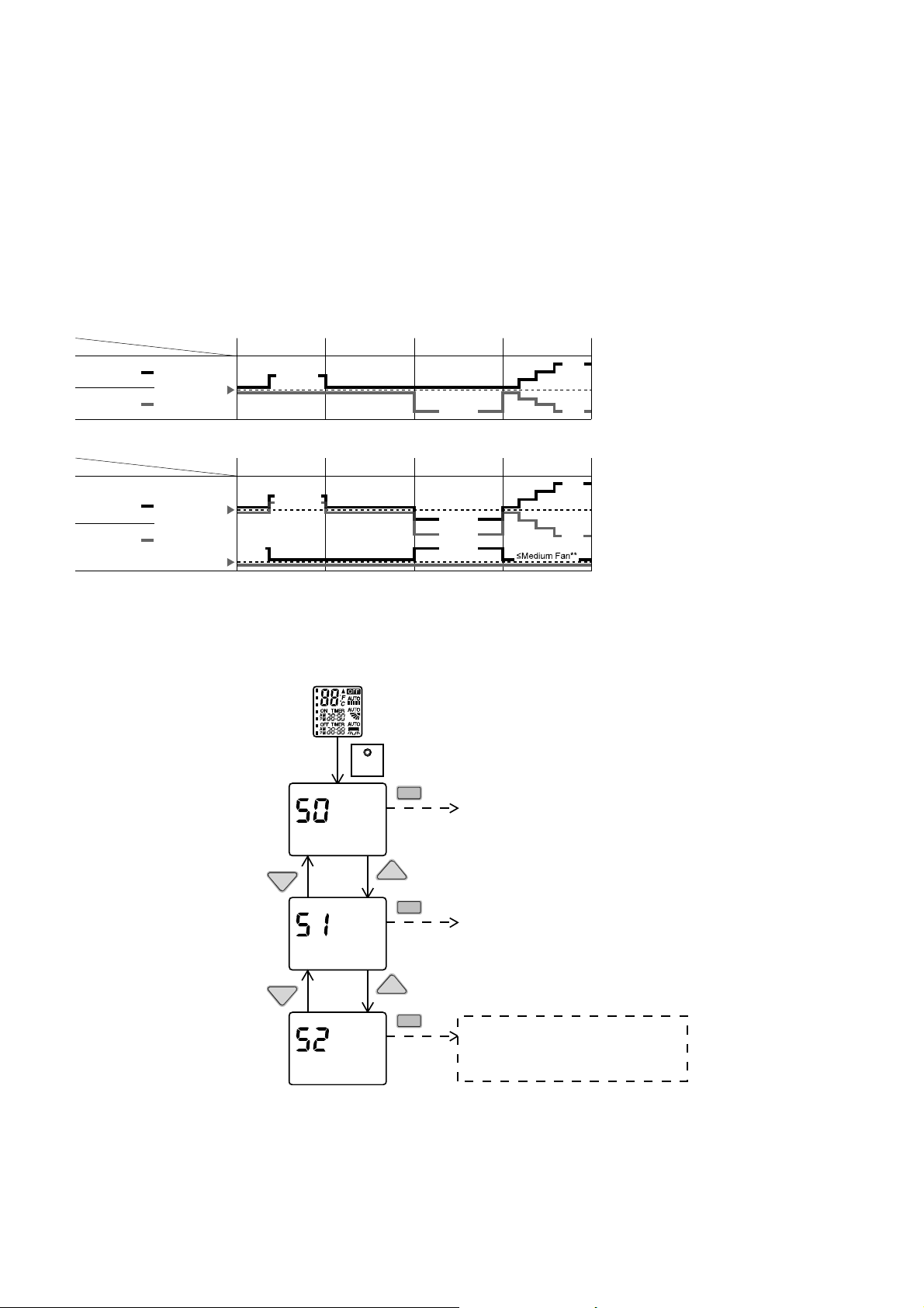
10.16.1 Human Activity Sensor Check Mode
To enable Human Activity sensor abnormality check mode, during ECONAVI operation ON:
During ECONAVI is ON, when CHECK signal received, if either sensors has abnormality, the 4 times abnormality
counter is ignored, ECONAVI Indicator will blink immediately and error code is memorized.
The unit could operate without ECONAVI or AUTO COMFORT.
The ECONAVI indicator blinking could be cancelled by pressing ECONAVI button again.
If the human activity sensor has no abnormality, the CHECK process will end and continue with normal operation.
Low activity Normal activity
Human
Mode
Set
temperature
High activity Absent
ECONA
V
I ; Detecting human presence and activity, the unit controls room temperature to save energy.
Low activity Normal activity
Human
Mode
Set
temperature
High activity Absent
Set
Fan Speed
AUTO COMFORT ; Detecting human presence and activity, the unit controls room temperature to keep human
comfortable consistently.
HEAT
COOL/DRY
HEAT
COOL/DRY
* During low activity, fan speed 1 tap up for first 15 minutes or until set temperature is reached.
** During human absence, maximum fan speed for COOL/DRY mode is medium fan.
+1 tap
+1 tap*
+2°F / +1°C
+2°F / +1°C
+0.5°F / +0.3°C
-2°F / -1°C
-4°F / -2°C
+4°F /
+2°C
-4°F /
-2°C
-4°F / -2°C
+4°F /
+2°C
-4°F /
-2°C
SET
Press continously for 5s
Remote control normal mode
TEMP
TEMP
SET
TEMP
TEMP
SET
SET
Transmit ECO demo c ode
and after 30 seconds return to normal
mode.
Transmit sunlight sensor check code
and after 30 seconds return to normal
mode.
Transmit check code
and after 30 seconds return to normal
mode.
30
11. Servicing Mode
11.1 Auto Off/On Button
Auto OFF/ON
Button pressed
Auto OFF/ON
Button pressed
Auto OFF/ON
Button pressed
5 sec
5 sec
Auto Operation Test Run Operation
(Forced Cooling Operation)
Stop Test Run Operation
(Forced Cooling Operation)
Stop
Beep Beep x 2
1 AUTO OPERATION MODE
The Auto operation will be activated immediately once the Auto OFF/ON button is pressed. This operation
can be used to operate air conditioner with limited function if remote control is misplaced or malfunction.
2 TEST RUN OPERATION (FOR PUMP DOWN/SERVICING PURPOSE)
The Test Run operation will be activated if the Auto OFF/ON button is pressed continuously for more than
5 seconds. A “beep” sound will heard at the fifth seconds, in order to identify the starting of Test Run
operation (Forced cooling operation). Within 5 minutes after Forced cooling operation start, the Auto OFF/ON
button is pressed for more than 5 seconds. A 2 “beep” sounds will heard at the fifth seconds, in order to
identify the starting of Forced heating operation.
The Auto OFF/ON button may be used together with remote control to set / change the advance setting of air
conditioner operation.
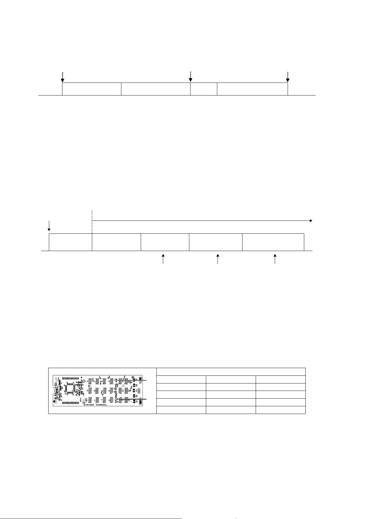
3 REMOTE CONTROL NUMBER SWITCH MODE
The Remote Control Number Switch Mode will be activated if the Auto OFF/ON button is pressed
continuously for more than 11 seconds (3 “beep” sounds will occur at 11th seconds to identify the Remote
Control Number Switch Mode is in standby condition) and press “AC RESET” button and then press any
button at remote control to transmit and store the desired transmission code to the EEPROM.
There are 4 types of remote control transmission code could be selected and stored in EEPROM of indoor
unit. The indoor unit will only operate when received signal with same transmission code from remote control.
This could prevent signal interference when there are 2 or more indoor units installed nearby together.
To change remote control transmission code, short or open jumpers at the remote control printed circuit
board.
Remote Control Printed Circuit Board
Jumper A (J1) Jumper B (D2) Remote Control No.
Short Open A (Default)
Open Open B
Short Short C
Open Short D
During Remote Control Number Switch Mode, press any button at remote control to transmit and store
the transmission code to the EEPROM.
4 REMOTE CONTROL RECEIVING SOUND OFF/ON MODE
The Remote Control Receiving Sound OFF/ON Mode will be activated if the Auto OFF/ON button is pressed
continuously for more than 16 seconds (4 “beep” sounds will occur at 16
th
seconds to identify the Remote
Control Receiving Sound OFF/ON Mode is in standby condition) and press “AC Reset” button at remote
control.
Auto OFF/ON button
pressed
Auto Operation
5sec 8sec 11sec 16sec
Tes t R un O per at i on
(Forced Cooling Operation)
Test Run Operation
(Forced Heating Operation)
Main unit always continue Test Run (forced cooling) operation
Beep Beep x 2
Press “AC RESET” Press “AC RESET”, then any
key at remote control
Press “AC RESET”
at remote control
Beep x 3 Beep x 4
Remote Control Number
Switch Mode
Remote Control Receiving
Sound OFF/ON
J1
D2

31
Press Auto OFF/ON button to toggle remote control receiving sound.
- Short “beep”: Turn OFF remote control receiving sound.
- Long “beep”: Turn ON remote control receiving sound.
After Auto OFF/ON button is pressed, the 20 seconds counter for Remote Control Receiving Sound OFF/ON
Mode is restarted.
11.2 Remote Control Button
11.2.1 SET Button
To check remote control transmission code and store the transmission code to EEPROM
o Press “Set” button continuously for 10 seconds by using pointer
o Press “Timer Set” button unit a “beep” sound is heard as confirmation of transmission code change.
11.2.2 RESET (RC)
To clear and restore the remote control setting to factory default.
o Press once to clear the memory
11.2.3 RESET (AC)
To restore the unit’s setting to factory default.
o Press once to restore the unit’s setting
11.2.4 TIMER ▲
To change indoor unit indicator’s LED intensity:
o Press continuously for 5 seconds.
11.2.5 TIMER ▼
To change remote control display from Degree Celsius (°C) to Degree Fahrenheit (°F)
o Press continuously for 10 seconds.
11.2.6 CLOCK Button
To change the remote control time format:
o Press for more than 5 seconds
32
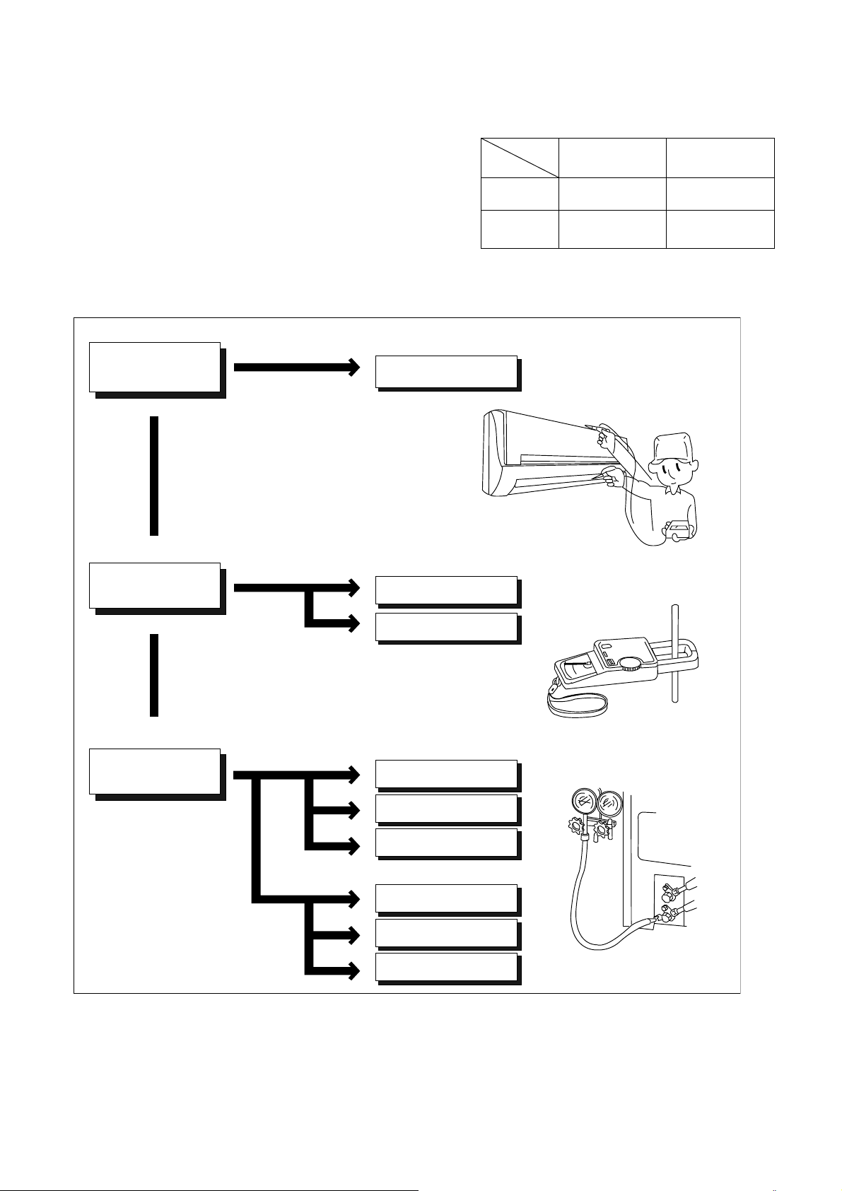
12. Troubleshooting Guide
12.1 Refrigeration Cycle System
In order to diagnose malfunctions, make sure that there are no
electrical problems before inspecting the refrigeration cycle.
Such problems include insufficient insulation, problem with the
power source, malfunction of a compressor and a fan.
The normal outlet air temperature and pressure of the
refrigeration cycle depends on various conditions, the standard
values for them are shown in the table on the right.
Value of electric
current during operation
Difference in the intake
and outlet
air temperatures
Lower than specified
Higher than specified
Cooling Mode
Heating Mode
High
Low
Low
Low
Low
Low
Gas side
pressure
Dusty condenser
preventing heat radiation
● Measuring electric current
during operation
● Measuring gas side pressure
Excessive amount
of refrigerant
Inefficient compressor
Insufficient refrigerant
Insufficient refrigerant
Inefficient compressor
Clogged strainer or
expansion valve
Clogged strainer or
capillary tube
Less than 14.4°F at the cooling mode.
Less than 25.2°F at the cooling mode.
More than 14.4°F
(15 minutes after an
operation is started.)
at cooling mode.
Above 25.2°F
(15 minutes after an
operation is started.)
at heating mode
Normal
● Measuring the air temperature
difference
Normal Pressure and Outlet Air Temperature (Standard)
Gas Pressure
PSI
(kg/cm
2
G)
Outlet air
Temperature
(°F)
Cooling Mode
130.53 ~ 174.04
(9 ~ 12)
53.6 ~ 60.8
Heating Mode
333.58 ~ 420.60
(23 ~ 29)
96.8 ~ 113
Condition: Indoor fan speed = High
Outdoor temperature 95°F at cooling mode
and 44.6°F at heating mode.
Compressor operate at rated frequency
33
12.1.1 Relationship between the condition of the air conditioner and pressure and
electric current
Carry out the measurements of pressure, electric current, and temperature fifteen minutes after an operation is
started.
edoMgnitaeHedoMgnilooC
Low Pressure High Pressure
Electric current
during operating
Low Pressure High Pressure
Electric current
during operating
Condition of the air
conditioner
Insufficient refrigerant
(gas leakage)
Clogged capillary tube
or Strainer
Short circuit in the
indoor unit
Heat radiation deficiency
of the outdoor unit
Inefficient compression
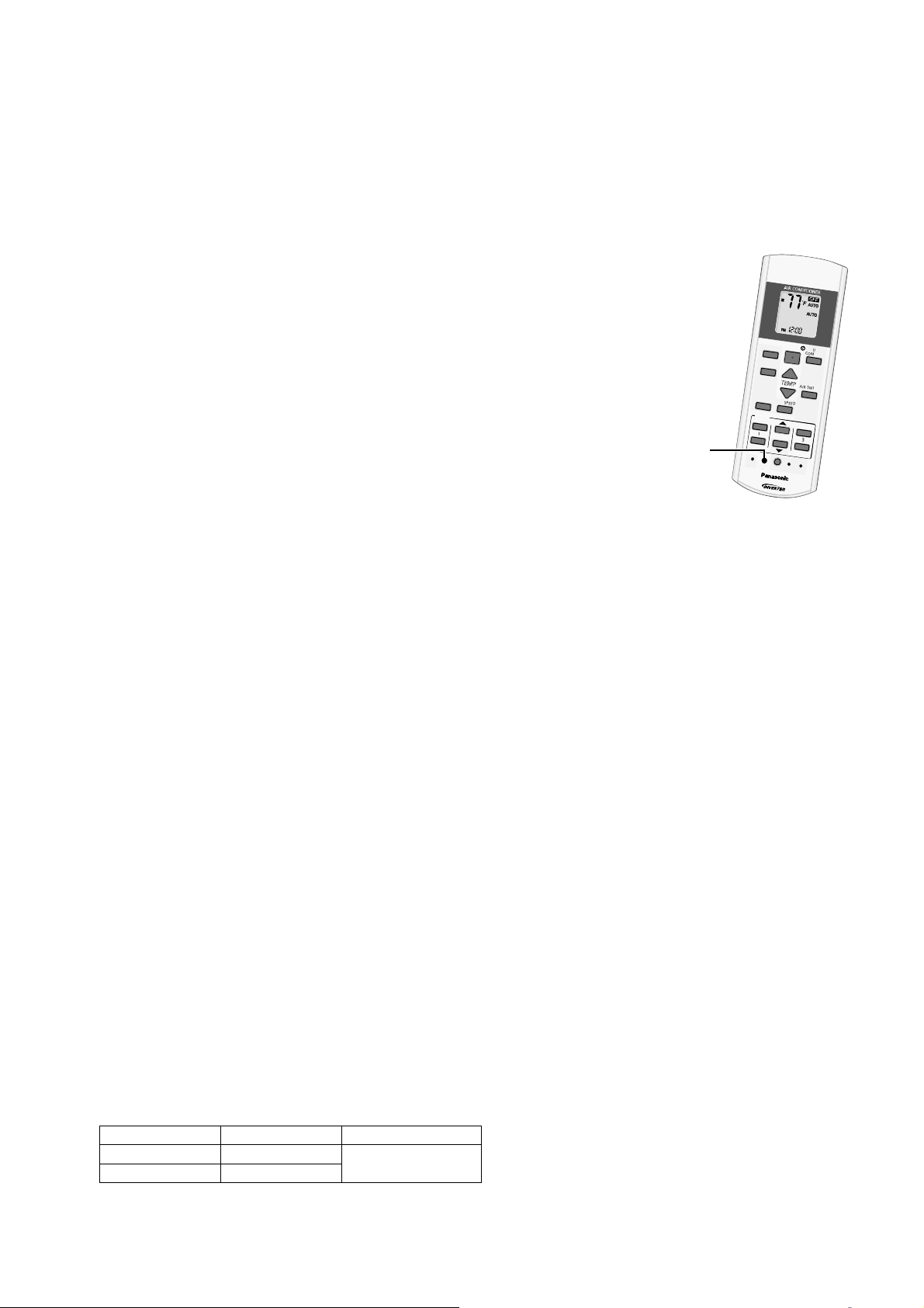
34
12.2 Breakdown Self Diagnosis Function
12.2.1 Self Diagnosis Function (Three Digits Alphanumeric Code)
Once error occurred during operation, the unit will stop its operation, and Timer LED blinks.
Although Timer LED goes off when power supply is turned off, if the unit is operated under a breakdown
condition, the LED will ON again.
In operation after breakdown repair, the Timer LED will not blink. The last error code (abnormality) will be stored
in IC memory.
12.2.2 To Make a Diagnosis
1 Timer LED starts to blink and the unit automatically stops the operation.
2 Press the CHECK button on the remote control continuously for
5 seconds.
3 “- -“ will be displayed on the remote control display.
Note: Display only for “- -“ (No signal transmission, no receiving sound
and no Power LED blinking)
4 Press the TIMER ▲ or ▼ button on the remote control. The code “H00”
(no abnormality) will be displayed and signal will be transmit to the main
unit.
5 Each press of the button (▲ or ▼) will increase error code number and
transmit error code signal to the main unit.
6 When the latest abnormality code on the main unit and code transmitted
from the remote control are matched, Power LED will light up for
30 seconds and a “beep” sound (continuously for 4 seconds) will be
heard. If no codes are matched, Power LED will light up for 0.5 seconds and no sound will be heard.
7 The breakdown diagnosis mode will be canceled unless pressing the CHECK button continuously for
5 seconds or operating the unit for 30 seconds.
8 The LED will be off if the unit is turned off or the RESET button on the main unit is pressed.
12.2.3 To Display Memorized Error Code (Protective Operation)
1 Turn power on.
2 Press the CHECK button on the remote control
3 “- -“ will be displayed on the remote control display.
Note: Display only for “- -“ (No signal transmission, no receiving sound and no Power LED blinking)
4 Press the TIMER ▲ or ▼ button on the remote control. The code “H00” (no abnormality) will be displayed
and signal will be transmit to the main unit.
5 Each press of the button (▲ or ▼) will increase error code number and transmit error code signal to the main
unit.
6 When the latest abnormality code on the main unit and code transmitted from the remote control are matched,
Power LED will light up for 30 seconds and a “beep” sound (continuously for 4 seconds) will be heard. If no
codes are matched, Power LED will light up for 0.5 seconds and no sound will be heard.
7 The breakdown diagnosis mode will be canceled unless pressing the CHECK button continuously for
5 seconds or operating the unit for 30 seconds.
8 The same diagnosis can be repeated by turning power on again.
12.2.4 To Clear Memorized Error Code after Repair (Protective Operation)
1 Turn power on (in standby condition).
2 Press the AUTO button for 5 seconds (a “beep” sound is heard) on the main unit to operate the unit at
Forced Cooling Operation Mode.
3 Press the CHECK button on the remote control for about 1 second with a pointed object to transmit signal to
main unit. A “beep” sound is heard, and the Error Code is cleared.
12.2.5 Temporary Operation (Depending On Breakdown Status)
1 Press the Auto OFF/ON button on the main unit (a “beep” sound is heard) to operate the unit. (Remote
control is enable again).
2 The unit can be temporarily be used until repaired.
Error Code Operation Temporary items
H23 Cooling
Emergency Operation
with limited power
H27, H28 Cooling, Heating
A
U
T
O
C
O
M
F
O
R
T
M
O
D
E
P
O
W
E
R
F
U
L
/
Q
U
I
E
T
T
E
M
P
O
F
F
/
O
N
T
I
M
E
R
S
E
T
C
A
N
C
E
L
O
N
O
F
F
1
2
3
A
I
R
S
W
I
N
G
F
A
N
S
P
E
E
D
S
E
T
C
H
E
C
K
C
L
O
C
K
R
E
S
E
T
A
C
R
C
E
C
O
N
A
V
I
F
A
N
S
P
E
E
D
A
I
R
S
W
I
N
G
A
U
T
O
H
E
A
T
C
O
O
L
D
R
Y
F
A
N
/
T
E
M
P
O
F
F
/
O
N
T
I
M
E
R
S
E
T
C
A
N
C
E
L
O
N
O
F
F
1
2
3
C
H
E
C
K
"Check" button
35
12.3 Error Code Table
Abnormality /
Protection control
Abnormality
Judgement
Protection
operation
Problem Check location
Diagnosis
display
——noitarepolamroN—eruliaffoyromemoN00H
H11 Indoor/outdoor
abnormal
communication
After operation for
1 minute
Indoor fan only
operation can
start by entering
into force cooling
operation
Indoor/outdoor
communication not establish
• Indoor/outdoor wire terminal
• Indoor/outdoor PCB
• Indoor/outdoor connection wire
H12 Indoor unit capacity
unmatched
90s after power
supply
— Total indoor capability more
than maximum limit or less
than minimum limit, or
number of indoor unit less
than two.
• Indoor/outdoor connection wire
• Indoor/outdoor PCB
• Specification and combination
table in catalogue
H14 Indoor intake air
temperature sensor
abnormality
Continuous for 5s — Indoor intake air temperature
sensor open or short circuit
• Indoor intake air temperature
sensor lead wire and connector
H15 Compressor
temperature sensor
abnormality
Continuous for 5s — Compressor temperature
sensor open or short circuit
• Compressor temperature sensor
lead wire and connector
H16 Outdoor current
transformer (CT)
abnormality
— — Current transformer faulty or
compressor faulty
• Outdoor PCB faulty or
compressor faulty
H19 Indoor fan motor
merchanism lock
Continuous
happen for 7 times
during ion device
off
— Indoor fan motor lock or
feedback abnormal
• Fan motor lead wire and
connector
• Fan motor lock or block
H23 Indoor heat exchanger
temperature sensor
abnormality
Continuous for 5s — Indoor heat exchanger
temperature sensor open or
short circuit
• Indoor heat exchanger
temperature sensor lead wire and
connector
H24 Indoor heat exchanger
temperature sensor 2
abnormality
Continuous for 5s — Indoor heat exchanger
temperature sensor 2 open
or short circuit
• Indoor heat exchanger
temperature sensor 2 lead wire
and connector
H25 Indoor ion device
abnormality
Port is ON for 10s — • ion device PCB
H27 Outdoor air temperature
sensor abnormality
Continuous for 5s — Outdoor air temperature
sensor open or short circuit
• Outdoor air temperature sensor
lead wire and connector
H28 Outdoor heat exchanger
temperature sensor 1
abnormality
Continuous for 5s — Outdoor heat exchanger
temperature sensor 1 open
or short circuit
• Outdoor heat exchanger
temperature sensor 1 lead wire
and connector
H30 Outdoor discharge pipe
temperature sensor
abnormality
Continuous for 5s — Outdoor discharge pipe
temperature sensor open or
short circuit
• Outdoor discharge pipe
temperature sensor lead wire and
connector
H33 Indoor / outdoor
misconnection
abnormality
— — Indoor and outdoor rated
voltage different
• Indoor and outdoor units check
H38 Indoor/Outdoor
mismatch (brand code)
— — Brand code not match
• Check indoor unit and outdoor
unit.
H32 Outdoor heat exchanger
temperature sensor 2
abnormality
Continuous for 5s — Outdoor heat exchanger
temperature sensor 2 open
or short circuit
• Outdoor heat exchanger
temperature sensor 2 lead wire
and connector
H34 Outdoor heat sink
temperature sensor
abnormality
Continuous for 2s — Outdoor heat sink
temperature sensor open
or short circuit
• Outdoor heat sink sensor
H36 Outdoor gas pipe
temperature sensor
abnormality
Continuous for 5s Heating protection
operation only
Outdoor gas pipe
temperature sensor open or
short circuit
• Outdoor gas pipe temperature
sensor lead wire and connector
H37 Outdoor liquid pipe
temperature sensor
abnormality
Continuous for 5s Cooling protection
operation only
Outdoor liquid pipe
temperature sensor open or
short circuit
• Outdoor liquid pipe temperature
sensor lead wire and connector
—
36
Note:
“○” – Frequency measured and fan speed fixed
The memory data of error code is erased when the power supply is cut off, or press the Auto Switch until “beep”
sound heard following by pressing the CHECK button at remote control.
Although operation forced to stop when abnormality detected, emergency operation is possible for certain errors
(refer to Error Code Table) by using remote control or Auto OFF/ON button at indoor unit. However, the remote
control signal receiving sound is changed from one “beep” to four “beep” sounds.
F91 Refrigeration cycle
abnormality
2 times happen
within 20 minutes
— Refrigeration cycle abnormal • Insufficient refrigerant or valve
close
F93 Compressor abnormal
revolution
4 times happen
within 20 minutes
— Compressor abnormal
revolution
• Power transistor module faulty or
compressor lock
F95 Outdoor cooling high
pressure protection
4 times happen
within 20 minutes
— Cooling high pressure
protection
• Check refrigeration system
• Outdoor air circuit
F94 Compressor discharge
overshoot protection
4 times happen
within 30 minutes
— Compressor discharge
pressure overshoot
• Check refrigeration system
F96 Power transistor module
overheating protection
4 times happen
within 30 minutes
— Power transistor module
overheat
• PCB faulty
• Outdoor air circuit (fan motor)
F97 Compressor
overheating protection
3 times happen
within 30 minutes
— Compressor overheat • Insufficient refrigerant
F98 Total running current
protection
3 times happen
within 20 minutes
— Total current protection • Check refrigeration system
• Power source or compressor lock
F99 Outdoor direct current
(DC) peak detection
Continuous
happen for 7 times
— Power transistor module
current protection
• Power transistor module faulty or
compressor lock
Abnormality /
Protection control
Abnormality
Judgement
Protection
operation
Problem Check location
Diagnosis
display
F11 4-way valve switching
abnormality
4 times happen
within 30 minutes
— 4-way valve switching
abnormal
•4-wayvalve
• Lead wire and connector.
F90 Power factor correction
(PFC) circuit protection
4 times happen
within 10 minutes
— Power factor correction
circuit abnormal
• Outdoor PCB faulty
H99 Indoor operating unit
freeze protection
— — Indoor freeze protection
(Cooling)
• Check indoor heat exchanger
• Air filter dirty
• Air circulation short circuit
F17 Indoor standby units
freezing abnormality
3 times happen
within 40 minutes
— Wrong wiring and connecting
pipe, expansion valve
leakage, indoor heat
exchanger sensor open
circuit
• Check indoor/outdoor connection
wire and pipe
• Indoor heat exchanger sensor
lead wire and connector
• Expansion valve lead wire and
connector.
H98 Indoor high pressure
protection
— — Indoor high pressure
protection (Heating)
• Check indoor heat exchanger
• Air filter dirty
• Air circulation short circuit
H97 Outdoor fan motor
mechanism lock
2 times happen
within 30 minutes
— Outdoor fan motor lock or
feedback abnormal
• Outdoor fan motor lead wire and
connector
• Fan motor lock or block
H64 Outdoor high pressure
sensor abnormality
Continuous for 1
minute
— High pressure sensor open
circuit during compressor
• High pressure sensor
• Lead wire and connector
H59 ECONAVI sensor
abnormality
Continuous for
25s
— ECOANVI sensor open or
short circuit
• ECONAVI sensor (defective or
disconnected)
• ECONAVI PCB
H41 Abnormal wiring or
piping connection
— — Wrongwiringand
connecting pipe, expansion
valve abnormality
• Check indoor/outdoor
connection wire and connection
pipe
• Expansion valve and lead wire
and connector
H39 Abnormal indoor
operating unit or
standby units
3 times happen
within 40 minutes
— Wrong wiring and connecting
pipe, expansion valve
abnormality, indoor heat
exchanger sensor open
circuit
• Check the indoor/outdoor
connection wire and connection
pipe.
• Indoor heat exchanger sensor
lead wire and connector.
• Expansion valve and lead wire
and connector system.
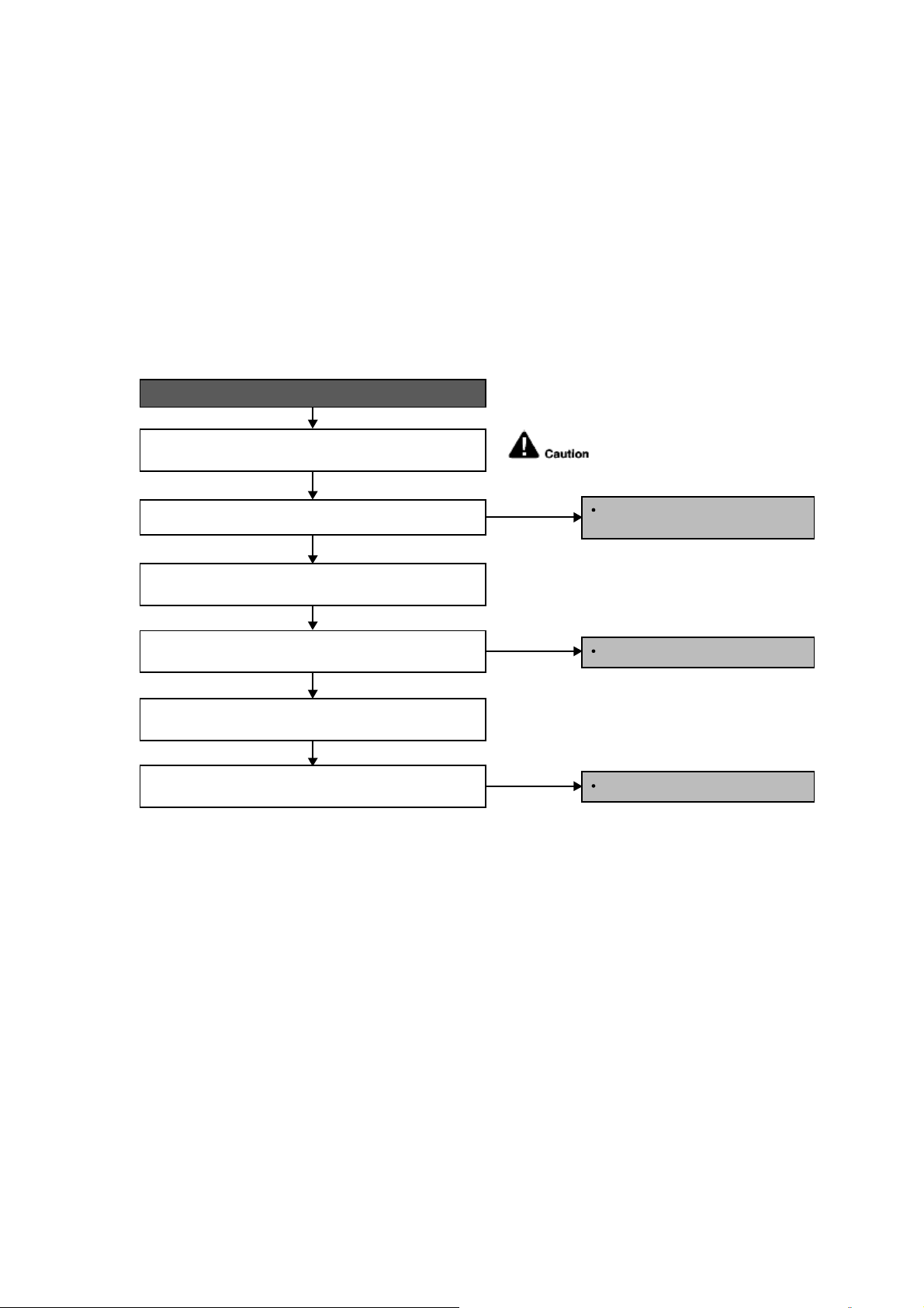
37
12.4 Self-diagnosis Method
12.4.1 H11 (Indoor/Outdoor Abnormal Communication)
Malfunction Decision Conditions
During startup and operation of cooling and heating, the data received from outdoor unit in indoor unit signal
transmission is checked whether it is normal.
Malfunction Caused
Faulty indoor unit PCB.
Faulty outdoor unit PCB.
Indoor unit-outdoor unit signal transmission error due to wrong wiring.
Indoor unit-outdoor unit signal transmission error due to breaking of wire in the connection wires between the
indoor and outdoor units.
Indoor unit-outdoor unit signal transmission error due to disturbed power supply waveform.
Troubleshooting
Check the indoor-outdoor units’ connection wires.
Is there any wiring error?
Disconnect terminal 3 wire and measure Vdc between terminal
2 & 3 from the outdoor unit.
Reconnect terminal 3 wire and measure Vdc between terminal
2 & 3 from the outdoor unit.
Is the Vdc fluctuate between 10~70Vdc?
Is the Vdc fluctuate between 10~70 Vdc?
When abnormality indication starts again.
For safety reason and to prevent
component breakdown, always switch
off the power before remove and
connect the component.
Replace indoor unit PCB.
Replace outdoor PCB.
Correct the indoor-outdoor units
connection wires.
NO
NO
NO
YES
YES
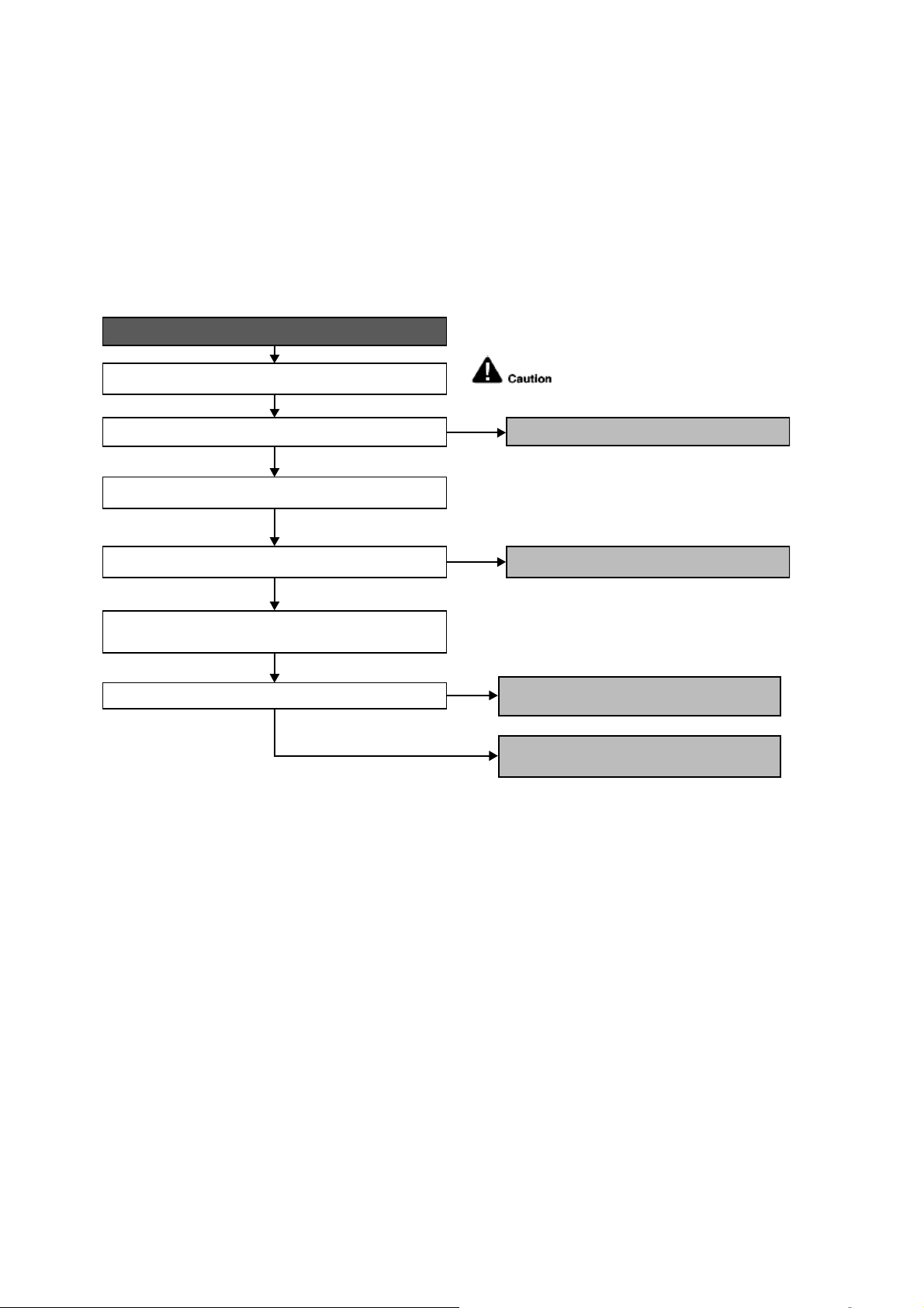
38
12.4.2 H12 (Indoor/Outdoor Capacity Rank Mismatched)
Malfunction Decision Conditions
During startup, error code appears when different types of indoor and outdoor units are interconnected.
Malfunction Caused
Wrong models interconnected.
Wrong indoor unit or outdoor unit PCBs mounted.
Indoor unit or outdoor unit PCBs defective.
Indoor-outdoor unit signal transmission error due to wrong wiring.
Indoor-outdoor unit signal transmission error due to breaking of wire 3 in the connection wires between the indoor
and outdoor units.
Troubleshooting
Check the indoor and outdoor unit connection wires.
Check indoor and outdoor units model number.
Is indoor unit and outdoor unit model numbers matched?
Check the spare part numbers of the indoor and outdoor unit
PCBs and compare with their Part Lists.
Matched compatibility?
Is there any wiring error?
When abnormality indication starts again.
For safety reason and to prevent
component breakdown, always switch
off the power before remove and
connect the component.
Correct the indoor-outdoor unit’s connection wires.
Change for the specified indoor or outdoor unit
PCB.
Replace the indoor and outdoor unit PCBs.
Match the compatible model(s).
NO
NO
NO
YES
YES
YES
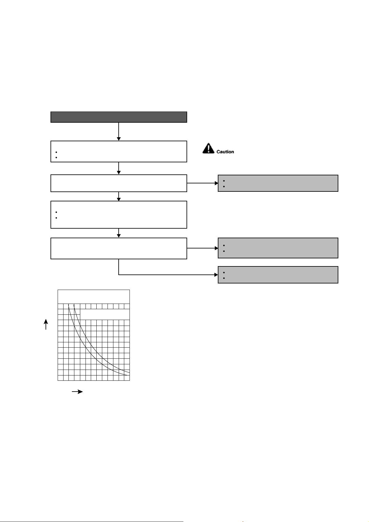
39
12.4.3 H14 (Indoor Intake Air Temperature Sensor Abnormality)
Malfunction Decision Conditions
During startup and operation of cooling and heating, the temperatures detected by the indoor intake air
temperature sensor are used to determine sensor errors.
Malfunction Caused
Faulty connector connection.
Faulty sensor.
Faulty PCB.
Troubleshooting
Check the connector connection:
Turn off the power.
Check the connector connection.
Is the connector connection normal?
When abnormality indication starts again.
For safety reason and to prevent component
breakdown, always switch off the power
before remove and connect the component.
Connector poor contact.
Correct the connection.
Defect in indoor unit PCB.
Replace the indoor unit PCB.
Defect in indoor intake air temperature sensor.
Replace the indoor intake air temperature sensor.
Check the indoor intake air temperature sensor:
Plug out connector from the indoor unit PCB.
Measure the resistance of the indoor intake air
temperature sensor.
Is the measured resistance of the indoor intake air
temperature sensor matches the value specified in its
characteristic chart?
NO
NO
YES
YES
0
10
14 50 68 86 104 12232
20
30
40
50
60
70
Temperature (°F)
Resistance (K
)
Sensor (Thermistor)
Characteristics
Pipe temp. Sensor
Intake Air Temp. Sensor
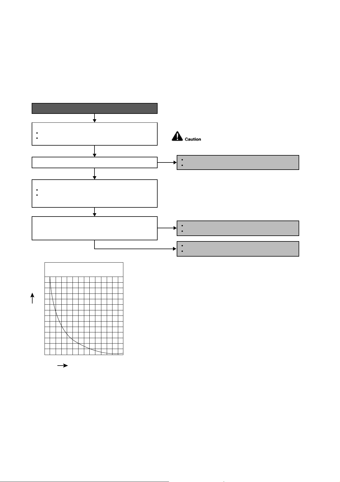
40
12.4.4 H15 (Compressor Temperature Sensor Abnormality)
Malfunction Decision Conditions
During startup and operation of cooling and heating, the temperatures detected by the outdoor compressor
temperature sensor are used to determine sensor errors.
Malfunction Caused
Faulty connector connection.
Faulty sensor.
Faulty PCB.
Troubleshooting
When abnormality indication starts again.
For safety reason and to prevent component
breakdown, always switch off the power
before remove and connect the component.
Connector poor contact.
Correct the connection.
Defect in outdoor compressor temperature sensor.
Replace the outdoor compressor temperature sensor.
Defect in outdoor unit PCB.
Replace the outdoor unit PCB.
Turn off the power.
Check the connector connection.
YES
YES
0
10
20
68 104 140 176 212 248 284
30
40
50
60
70
Temperature (°F)
Resistance (K
)
Compressor Temp. Sensor
(Thermistor) Charateristics
Check the connector connection:
Plug out connector from the outdoor unit PCB.
Measure the resistance of the outdoor compressor
temperature sensor.
Check the outdoor compressor temperature sensor:
Is the connector connection normal?
Is the measured resistance of the outdoor compressor
temperature sensor matches the value specified in its
characteristic chart?
NO
NO
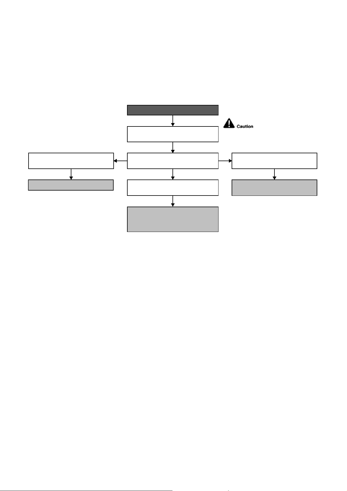
41
12.4.5 H16 (Outdoor Current Transformer)
Malfunction Decision Conditions
An input current, detected by Current Transformer CT, is below threshold value when the compressor is
operating at certain frequency value for 3 minutes.
Malfunction Caused
Lack of gas.
Broken CT (current transformer).
Broken Outdoor PCB.
Troubleshooting
For safety reason and to
prevent component breakdown,
always switch off the power before
remove and connect the component.
When abnormality indication starts again.
● Check for gas leaking source; Repair
or replace defected part(s).
● Capillary tube/expansion valve
blockage; Replace defected part(s).
● Compressor Lack Compression.
● Replace Compressor.
● Check & replace defected CT.
Refer to Service Manual Technical Graph
for Temp vs Current and Pressure.
In forced cooling, check suction pressure
versus running current.
Suction pressure and running current is
normal.
Running current is much too low and
suction pressure is much too high.
Running current and suction pressure is
very low.

42
12.4.6 H19 (Indoor Fan Motor – DC Motor Mechanism Locked)
Malfunction Decision Conditions
The rotation speed detected by the Hall IC during fan motor operation is used to determine abnormal fan motor
(feedback of rotation > 2550rpm or < 50rpm)
Malfunction Caused
Operation stops due to short circuit inside the fan motor winding.
Operation stops due to breaking of wire inside the fan motor.
Operation stops due to breaking of fan motor lead wires.
Operation stops due to Hall IC malfunction.
Operation error due to faulty indoor unit PCB.
Troubleshooting
Turn off power supply and rotate fan by hand.
When abnormality indication starts again.
Replace fan motor.
Does fan rotate smoothly?
Turn power supply on and operate fan.
Does it rotate? Stop fan motor.
Check the rotation feedback output from fan motor.
Rotate the fan motor by hand, is the rotation
feedback voltage 15Vdc (pin 7 & 4) generated?
Turn off power supply and disconnect fan motor connector,
then turn power on.
Check the output of fan motor from indoor PCB.
Is the motor power supply voltage~325Vdc (pin 1 & 4)
generated?
Is the motor control voltage 15Vdc (pin 5 & 4) generated?
Operate the fan, is the rotation command voltage 1~5Vdc
(pin 6 & 4) generated?
NO
NO
NO
NO
NO
NO
YES
YES
YES
YES
For safety reason and to prevent
component breakdown, always switch
off the power before remove and
connect the component.
Replace indoor PCB.
Replace fan motor.
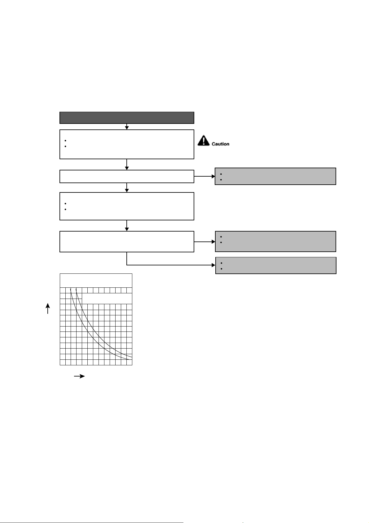
43
12.4.7 H23 (Indoor Pipe Temperature Sensor Abnormality)
Malfunction Decision Conditions
During startup and operation of cooling and heating, the temperatures detected by the indoor heat exchanger
temperature sensor are used to determine sensor errors.
Malfunction Caused
Faulty connector connection.
Faulty sensor.
Faulty PCB.
Troubleshooting
When abnormality indication starts again.
For safety reason and to prevent component
breakdown, always switch off the power
before remove and connect the component.
Connector poor contact.
Correct the connection.
Defect in outdoor unit PCB.
Replace the outdoor unit PCB.
Defect in outdoor intake air temperature sensor.
Replace the outdoor intake air temperature
sensor.
NO
NO
YES
YES
0
10
14 50 68 86 104 12232
20
30
40
50
60
70
Temperature (°F)
Resistance (K
)
Sensor (Thermistor)
Characteristics
Pipe temp. Sensor
Intake Air Temp. Sensor
Check the connector connection:
Plug out connector from the indoor unit PCB.
Is the connector connection normal?
Measure the resistance of the indoor pipe temperature
sensor.
Check the outdoor air temperature sensor:
Is the measured resistance of the outdoor intake air
temperature sensor matches the value specified in its
characteristic chart?
Plug out connector from the outdoor unit PCB.
Measure the resistance of the outdoor intake air
temperature sensor.
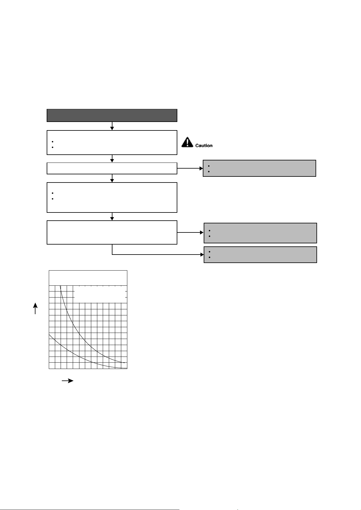
44
12.4.8 H27 (Outdoor Air Temperature Sensor Abnormality)
Malfunction Decision Conditions
During startup and operation of cooling and heating, the temperatures detected by the outdoor air temperature
sensor are used to determine sensor errors.
Malfunction Caused
Faulty connector connection.
Faulty sensor.
Faulty PCB.
Troubleshooting
Check the connector connection:
Is the measured resistance of the outdoor air temperature
sensor matches the value specified in its characteristic
chart?
Is the connector connection normal?
When abnormality indication starts again.
For safety reason and to prevent component
breakdown, always switch off the power
before remove and connect the component.
Turn off the power.
Check the connector connection.
Defect in outdoor air temperature sensor.
Replace the outdoor air temperature sensor.
Defect in outdoor unit PCB.
Replace the outdoor unit PCB.
NO
NO
YES
YES
Check the outdoor air temperature sensor:
Plug out connector from the outdoor unit PCB.
Measure the resistance of the outdoor air temperature
sensor.
Connector poor contact.
Correct the connection.
0
10
14 50 68 86 104 12232
20
30
40
50
60
70
Temperature (°F)
Resistance (K
)
Sensor (Thermistor)
Characteristics
Outdoor Air Sensor
Outdoor Heat Exchanger
Sensor
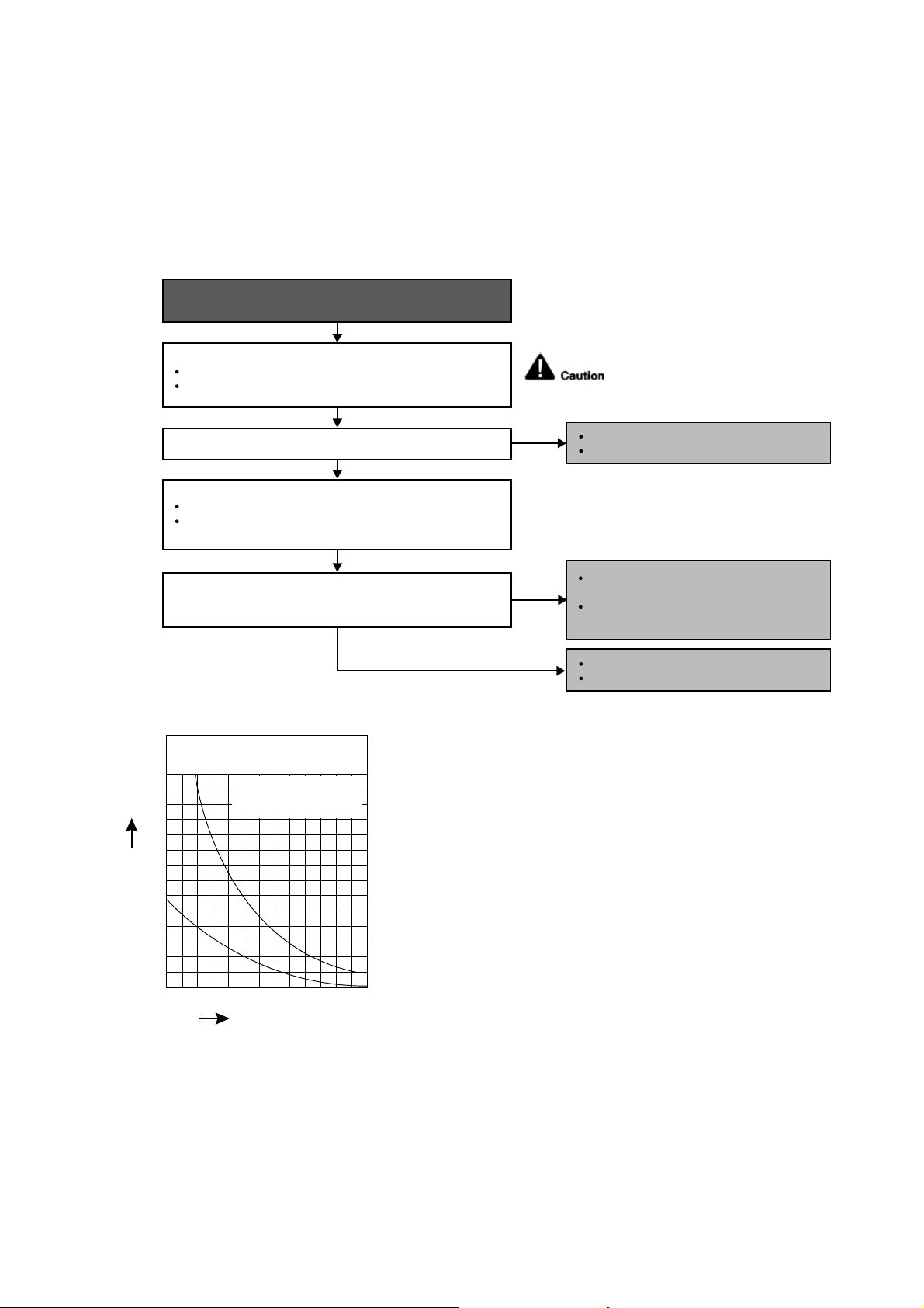
45
12.4.9 H28 (Outdoor Pipe Temperature Sensor Abnormality)
Malfunction Decision Conditions
During startup and operation of cooling and heating, the temperatures detected by the outdoor pipe temperature
sensor are used to determine sensor errors.
Malfunction Caused
Faulty connector connection.
Faulty sensor.
Faulty PCB.
Troubleshooting
Is the measured resistance of the outdoor heat exchanger
temperature sensor matches the value specified in its
characteristic chart?
Is the connector connection normal?
When abnormality indication starts again.
For safety reason and to prevent
component breakdown, always switch
off the power before remove and
connect the component.
No
No
YES
YES
Check the outdoor heat exchanger temperature sensor:
Plug out connector from the outdoor unit PCB.
Measure the resistance of the outdoor heat exchanger
temperature sensor.
0
10
14 50 68 86 104 12232
20
30
40
50
60
70
Temperature (°F)
Resistance (K
)
Sensor (Thermistor)
Characteristics
Outdoor Air Sensor
Outdoor Heat Exchanger
Sensor
Check the connector connection:
Turn off the power.
Check the connector connection.
Connector poor contact.
Correct the connection.
Defect in outdoor unit PCB.
Replace the outdoor unit PCB.
Defect in outdoor heat exchanger
temperature sensor.
Replace the outdoor heat exchanger
temperature sensor.
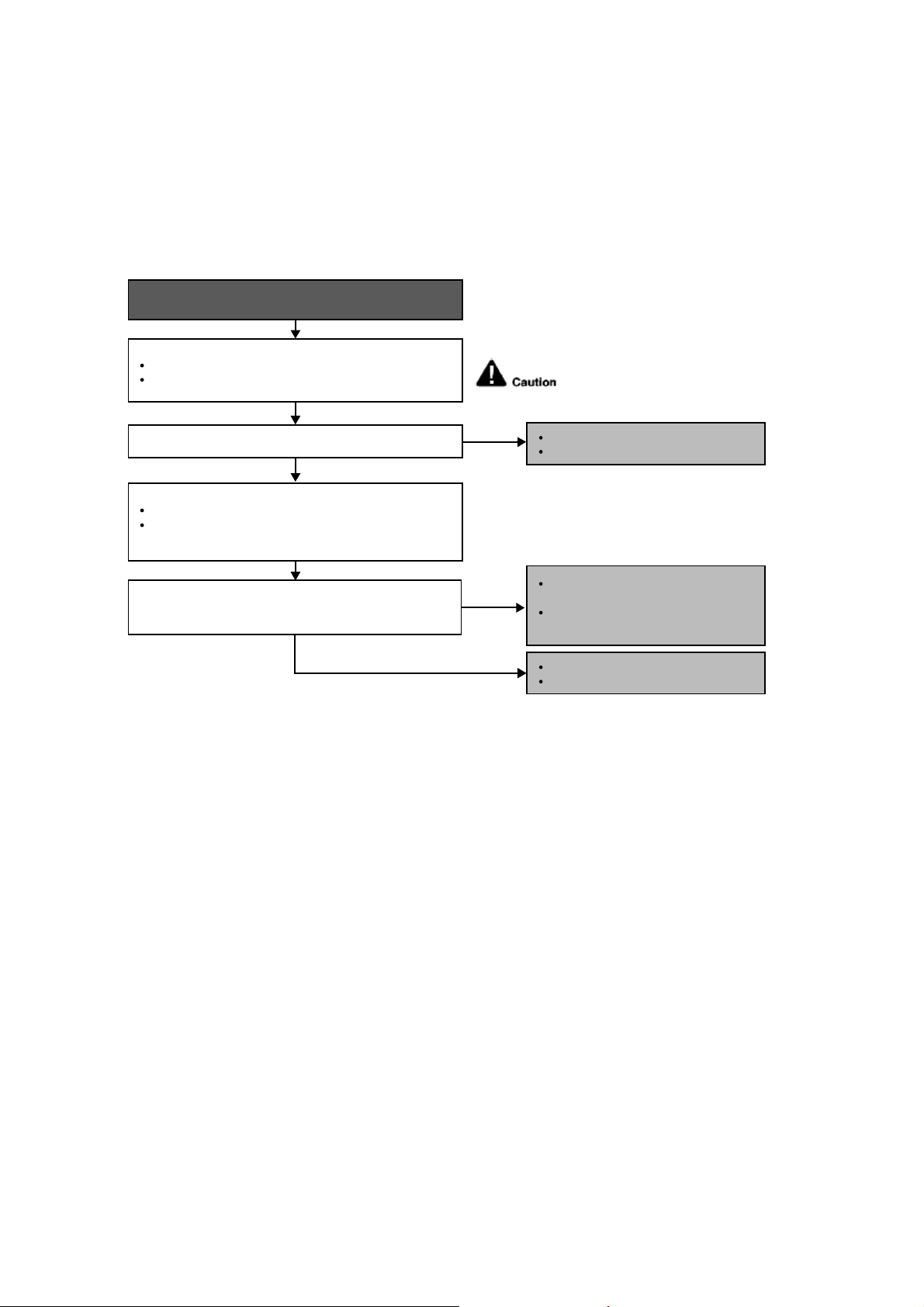
46
12.4.10 H30 (Compressor Discharge Temperature Sensor Abnormality)
Malfunction Decision Conditions
During startup and operation of cooling and heating, the temperatures detected by the outdoor discharge pipe
temperature sensor are used to determine sensor errors.
Malfunction Caused
Faulty connector connection.
Faulty sensor.
Faulty PCB.
Troubleshooting
When abnormality indication starts again.
For safety reason and to prevent
component breakdown, always switch
off the power before remove and
connect the component.
Is the measured resistance of the outdoor discharge pipe
temperature sensor matches the value specified in its
characteristic chart?
Is the connector connection normal?
YES
YES
Check the outdoor discharge pipe temperature sensor:
Plug out connector from the outdoor unit PCB.
Measure the resistance of the outdoor discharge pipe
temperature sensor.
Check the connector connection:
Turn off the power.
Check the connector connection.
Connector poor contact.
Correct the connection.
Defect in outdoor unit PCB.
Replace the outdoor unit PCB.
Defect in outdoor discharge pipe
temperature sensor.
Replace the outdoor discharge pipe
temperature sensor.
NO
NO
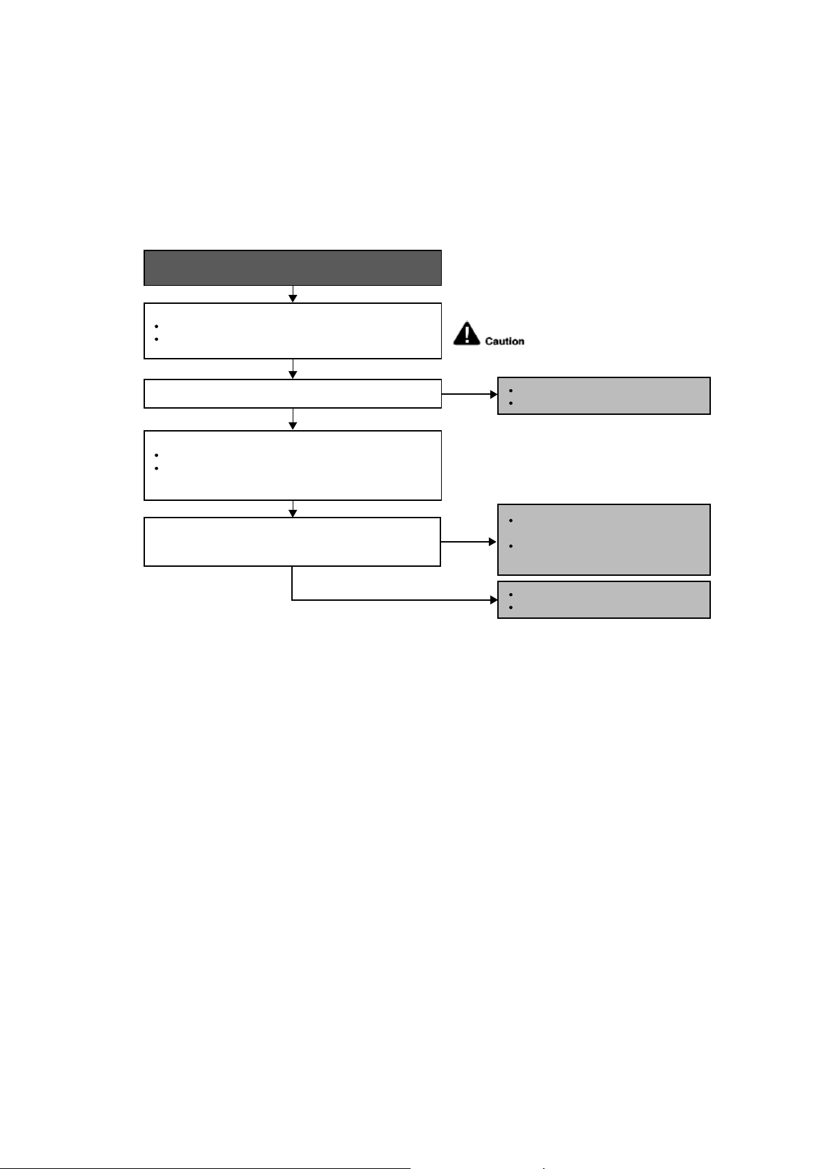
47
12.4.11 H32 (Outdoor Heat Exchanger Temperature Sensor 2 Abnormality)
Malfunction Decision Conditions
During startup and operation of cooling and heating, the temperatures detected by the outdoor heat exchanger
temperature sensor are used to determine sensor errors.
Malfunction Caused
Faulty connector connection.
Faulty sensor.
Faulty PCB.
Troubleshooting
When abnormality indication starts again.
For safety reason and to prevent
component breakdown, always switch
off the power before remove and
connect the component.
Is the measured resistance of the outdoor heat exchanger
temperature sensor matches the value specified in its
characteristic chart?
Is the connector connection normal?
YES
YES
Check the outdoor discharge pipe temperature sensor:
Plug out connector from the outdoor unit PCB.
Measure the resistance of the outdoor discharge pipe
temperature sensor.
Check the connector connection:
Turn off the power.
Check the connector connection.
Connector poor contact.
Correct the connection.
Defect in outdoor unit PCB.
Replace the outdoor unit PCB.
Defect in outdoor discharge pipe
temperature sensor.
Replace the outdoor discharge pipe
temperature sensor.
NO
NO
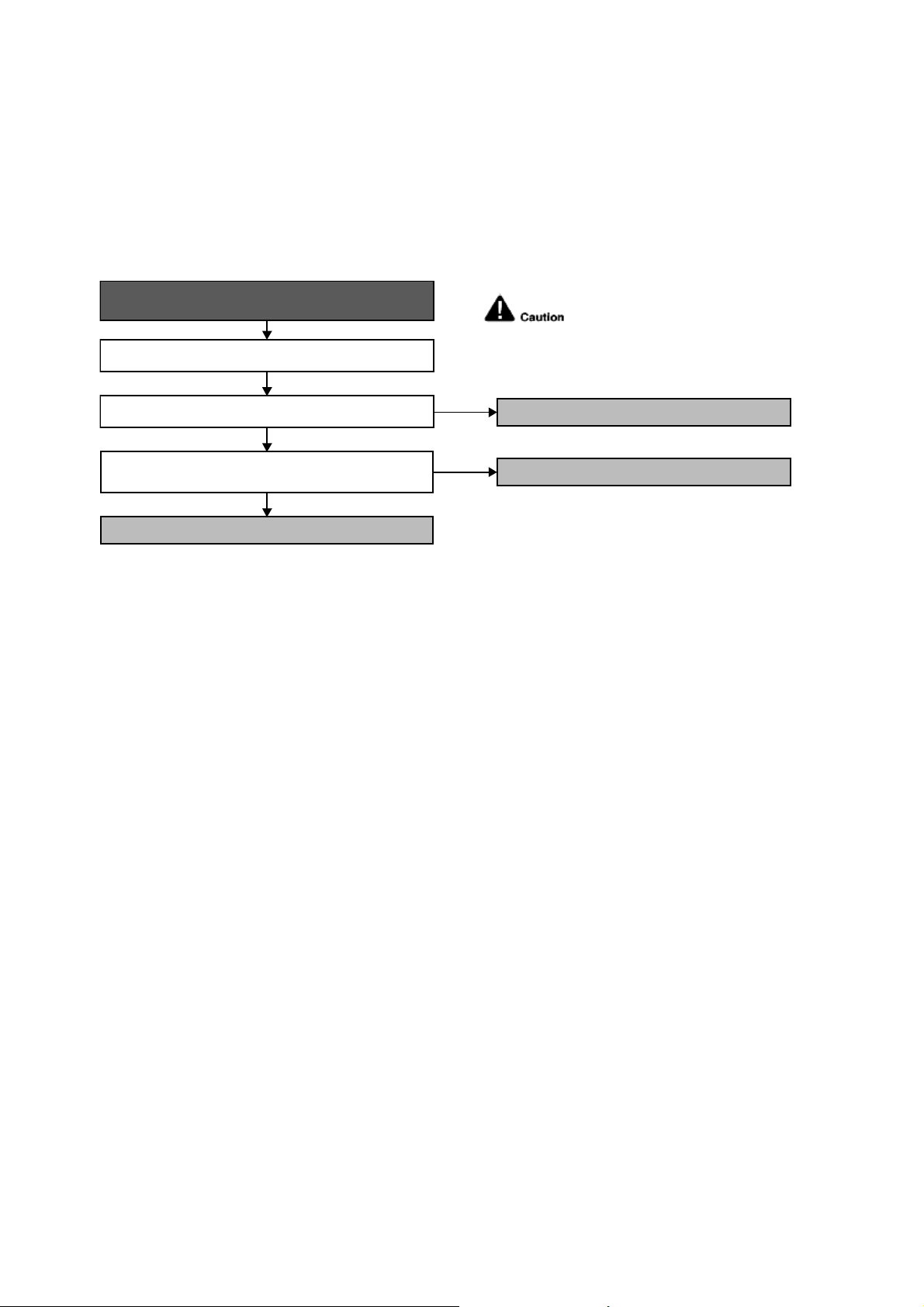
48
12.4.12 H33 (Unspecified Voltage between Indoor and Outdoor)
Malfunction Decision Conditions
The supply power is detected for its requirement by the indoor/outdoor transmission.
Malfunction Caused
Wrong models interconnected.
Wrong indoor unit and outdoor unit PCBs used.
Indoor unit or outdoor unit PCB defective.
Troubleshooting
When abnormality indication starts again.
For safety reason and to prevent
component breakdown, always switch
off the power before remove and
connect the component.
Check indoor and outdoor units model number.
Check indoor and outdoor PCB part number and compare if
they matched the part list.
NO
NO
Is the indoor and outdoor unit model number matched?
● Match the compatible model (follow specification).
YES
● Replace the indoor and outdoor unit PCB.
Change for the specified indoor or outdoor unit PCB.
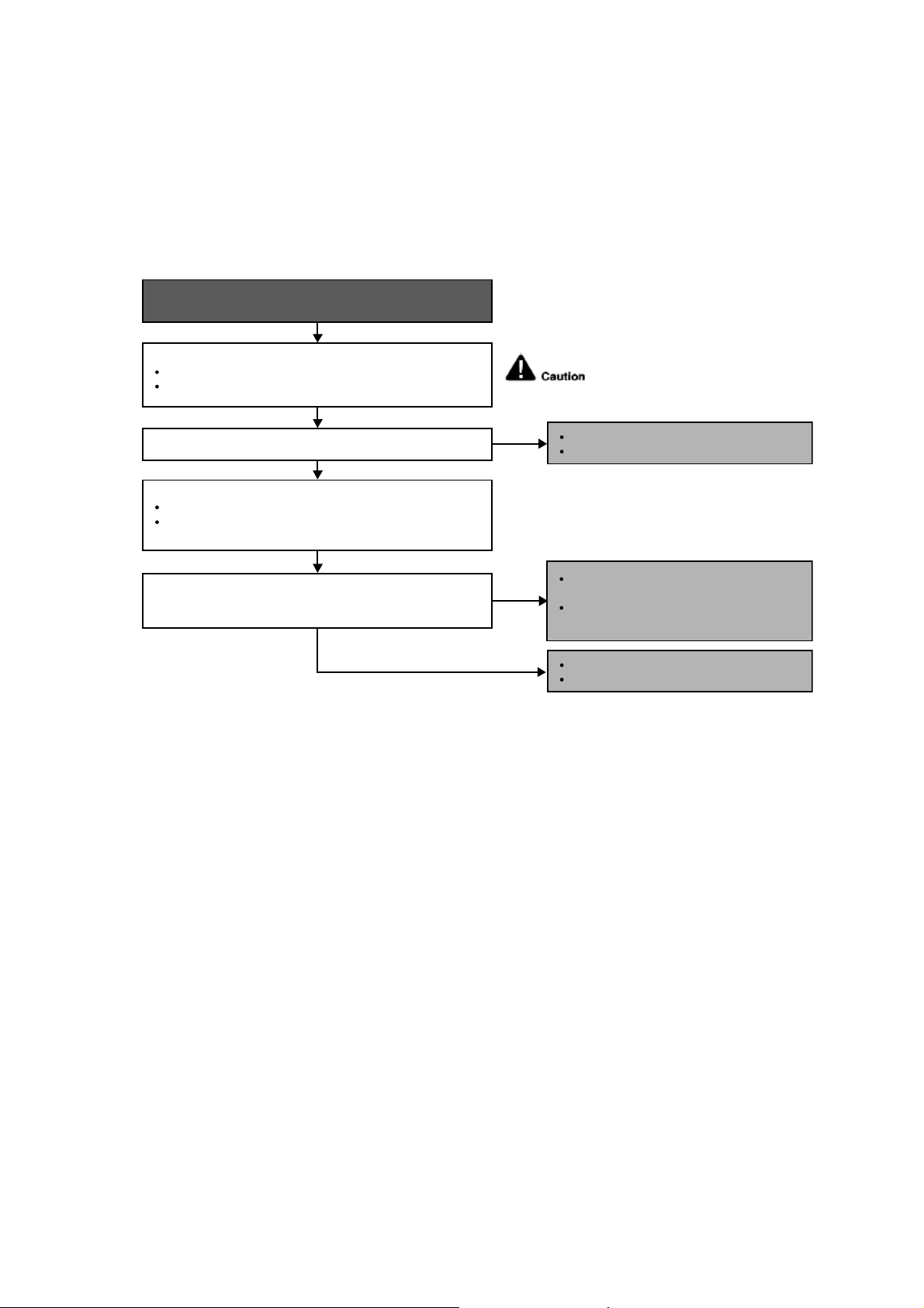
49
12.4.13 H34 (Outdoor Heat Sink Temperature Sensor Abnormality)
Malfunction Decision Conditions
During startup and operation of cooling and heating, the temperatures detected by the outdoor heat sink
temperature sensor are used to determine sensor errors.
Malfunction Caused
Faulty connector connection.
Faulty sensor.
Faulty PCB.
Troubleshooting
Is the measured resistance of the outdoor gas pipe
temperature sensor matches the value specified in its
characteristic chart?
Is the connector connection normal?
When abnormality indication starts again.
For safety reason and to prevent
component breakdown, always switch
off the power before remove and
connect the component.
No
No
YES
YES
Check the outdoor discharge pipe temperature sensor:
Plug out connector from the outdoor unit PCB.
Measure the resistance of the outdoor discharge pipe
temperature sensor.
Check the connector connection:
Turn off the power.
Check the connector connection.
Connector poor contact.
Correct the connection.
Defect in outdoor unit PCB.
Replace the outdoor unit PCB.
Defect in outdoor heat exchanger
temperature sensor.
Replace the outdoor discharge pipe
temperature sensor.
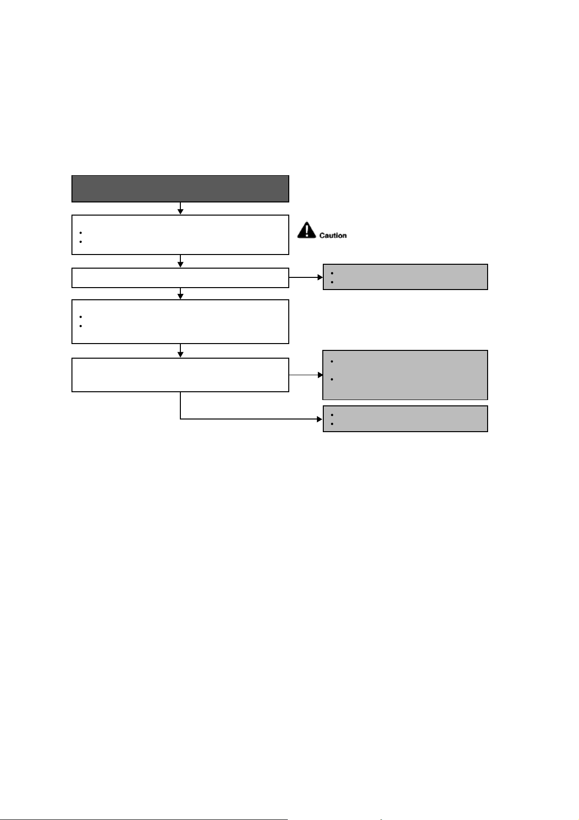
50
12.4.14 H36 (Outdoor Gas Pipe Sensor Abnormality)
Malfunction Decision Conditions
During startup and operation of cooling and heating, the temperatures detected by the outdoor gas pipe
temperature sensor are used to determine sensor errors.
Malfunction Caused
Faulty connector connection.
Faulty sensor.
Faulty PCB.
Troubleshooting
Is the measured resistance of the outdoor gas pipe
temperature sensor matches the value specified in its
characteristic chart?
Is the connector connection normal?
When abnormality indication starts again.
For safety reason and to prevent
component breakdown, always switch
off the power before remove and
connect the component.
NO
NO
YES
YES
Check the outdoor discharge pipe temperature sensor:
Plug out connector from the outdoor unit PCB.
Measure the resistance of the outdoor discharge pipe
temperature sensor.
Check the connector connection:
Turn off the power.
Check the connector connection.
Connector poor contact.
Correct the connection.
Defect in outdoor unit PCB.
Replace the outdoor unit PCB.
Defect in outdoor discharge pipe
temperature sensor.
Replace the outdoor discharge pipe
temperature sensor.

51
12.4.15 H37 (Outdoor Liquid Pipe Temperature Sensor Abnormality)
Malfunction Decision Conditions
During startup and operation of cooling and heating, the temperatures detected by the outdoor liquid pipe
temperature sensor are used to determine sensor errors.
Malfunction Caused
Faulty connector connection.
Faulty sensor.
Faulty PCB.
Troubleshooting
Is the measured resistance of the outdoor liquid pipe
temperature sensor matches the value specified in its
characteristic chart?
Is the connector connection normal?
When abnormality indication starts again.
For safety reason and to prevent
component breakdown, always switch
off the power before remove and
connect the component.
NO
NO
YES
YES
Check the outdoor discharge pipe temperature sensor:
Plug out connector from the outdoor unit PCB.
Measure the resistance of the outdoor discharge pipe
temperature sensor.
Check the connector connection:
Turn off the power.
Check the connector connection.
Connector poor contact.
Correct the connection.
Defect in outdoor unit PCB.
Replace the outdoor unit PCB.
Defect in outdoor discharge pipe
temperature sensor.
Replace the outdoor discharge pipe
temperature sensor.
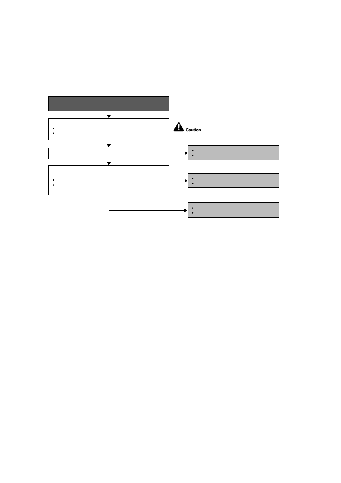
52
12.4.16 H59 (Human Activity Sensor Abnormality)
Malfunction Decision Conditions
Feedback signal of human activity sensor.
Malfunction Caused
Feedback signal is fixed at 0 VDC or 5 VDC continuously for 25 seconds during ECONAVI or AUTO COMFORT
operation.
Feedback signal is detected during ECONAVI or AUTO COMFORT off.
Troubleshooting
Is the connector connection normal?
When abnormality indication starts again.
For safety reason and to prevent
component breakdown, always switch
off the power before remove and
connect the component.
NO
YES
YES
Check if the feedback signal of human activity sensor
(pin 2 and 3) is normal.
When no motion, feedback is 0V.
When motion detected, feedback is between 1.5VDC
to 2.5VDC.
Check the connector connection:
Turn off the power.
Check the connector connection.
Connector poor contact.
Correct the connection.
Defect in outdoor unit PCB.
Replace the outdoor unit PCB.
NO
Defect in human activity sensor.
Replace the human activity sensor.
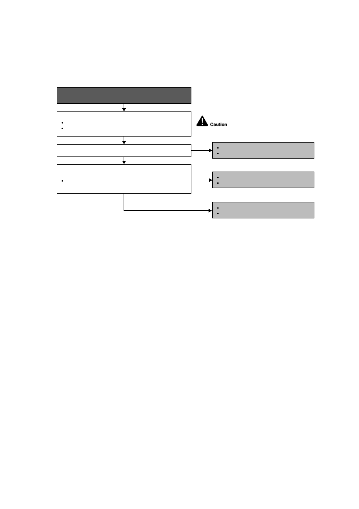
53
12.4.17 H70 (Light Sensor Abnormality)
Malfunction Decision Conditions
Feedback signal of light sensor.
Malfunction Caused
Feedback value is 0 VDC continuously.
Troubleshooting
Is the connector connection normal?
When abnormality indication starts again.
For safety reason and to prevent
component breakdown, always switch
off the power before remove and
connect the component.
NO
YES
YES
Check if the feedback signal of sunlight sensor (pin 11 and 13)
is normal.
Depends on indoor light intensity, feedback voltage
= 0.06 ~ 4.8 VDC (from dim to bright).
Check the connector connection:
Turn off the power.
Check the connector connection.
Connector poor contact.
Correct the connection.
Defect in indoor unit PCB.
Replace the indoor unit PCB.
NO
Defect in sunlight sensor.
Replace the sinlight sensor.
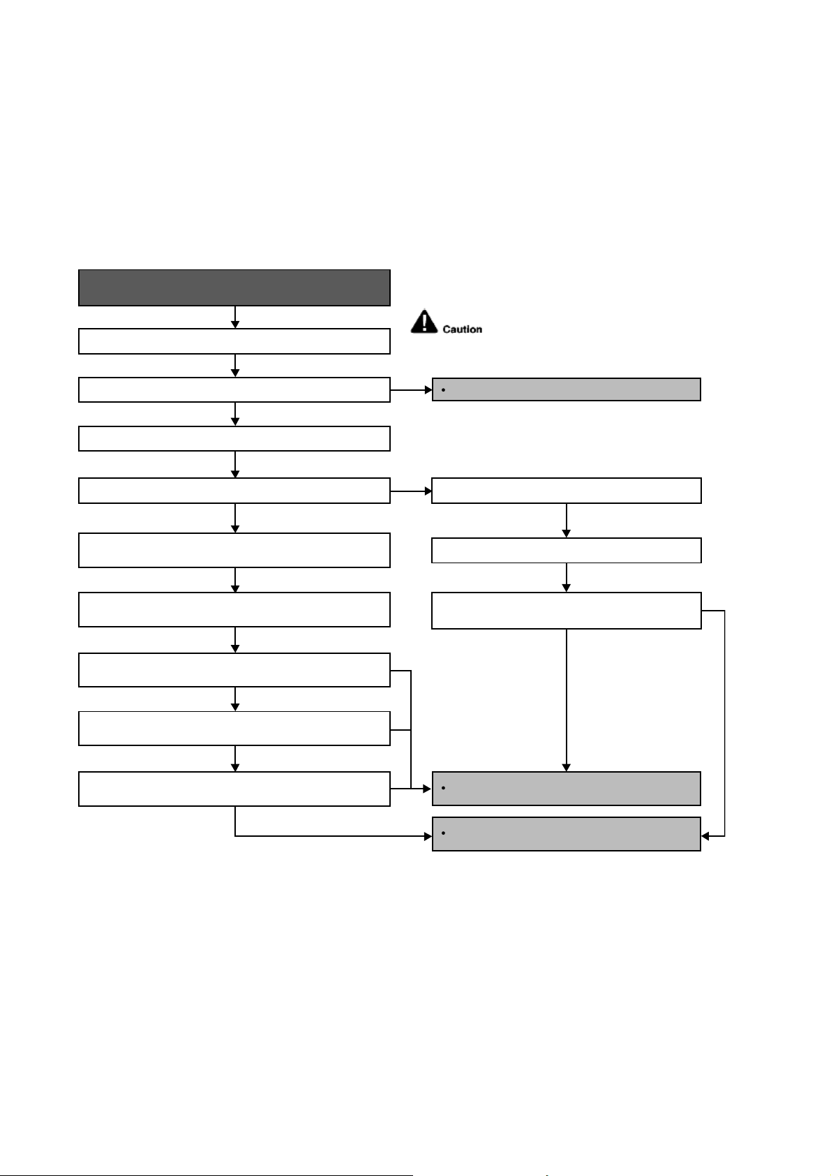
54
12.4.18 H97 (Outdoor Fan Motor – DC Motor Mechanism Locked)
Malfunction Decision Conditions
The rotation speed detected by the Hall IC during fan motor operation is used to determine abnormal fan motor.
Malfunction Caused
Operation stops due to short circuit inside the fan motor winding.
Operation stops due to breaking of wire inside the fan motor.
Operation stops due to breaking of fan motor lead wires.
Operation stops due to Hall IC malfunction.
Operation error due to faulty outdoor unit PCB.
Troubleshooting
Turn off power supply and rotate fan by hand.
When abnormality indication starts again.
Replace fan motor.
Does fan rotate smoothly?
Turn power supply on and operate fan.
Does it rotate? Stop fan motor.
Check the rotation feedback output from fan motor.
Rotate the fan motor by hand, is the rotation feedback
voltage 15 Vdc (pin 1 & 4) generated?
Turn off power supply and disconnect fan motor connector,
then turn power on.
Check the output of fan motor from outdoor PCB.
Is the motor power supply voltage ~325Vdc (pin 7 & 4)
generated?
Is the motor control voltage 15Vdc (pin 3 & 4) generated?
Operate the fan, is the rotation command voltage 1~5Vdc (pin 2
& 4) generated?
NO
NO
NO
NO
NO
NO
YES
YES
YES
YES
For safety reason and to prevent
component breakdown, always switch
off the power before remove and
connect the component.
Replace outdoor PCB.
Replace fan motor.
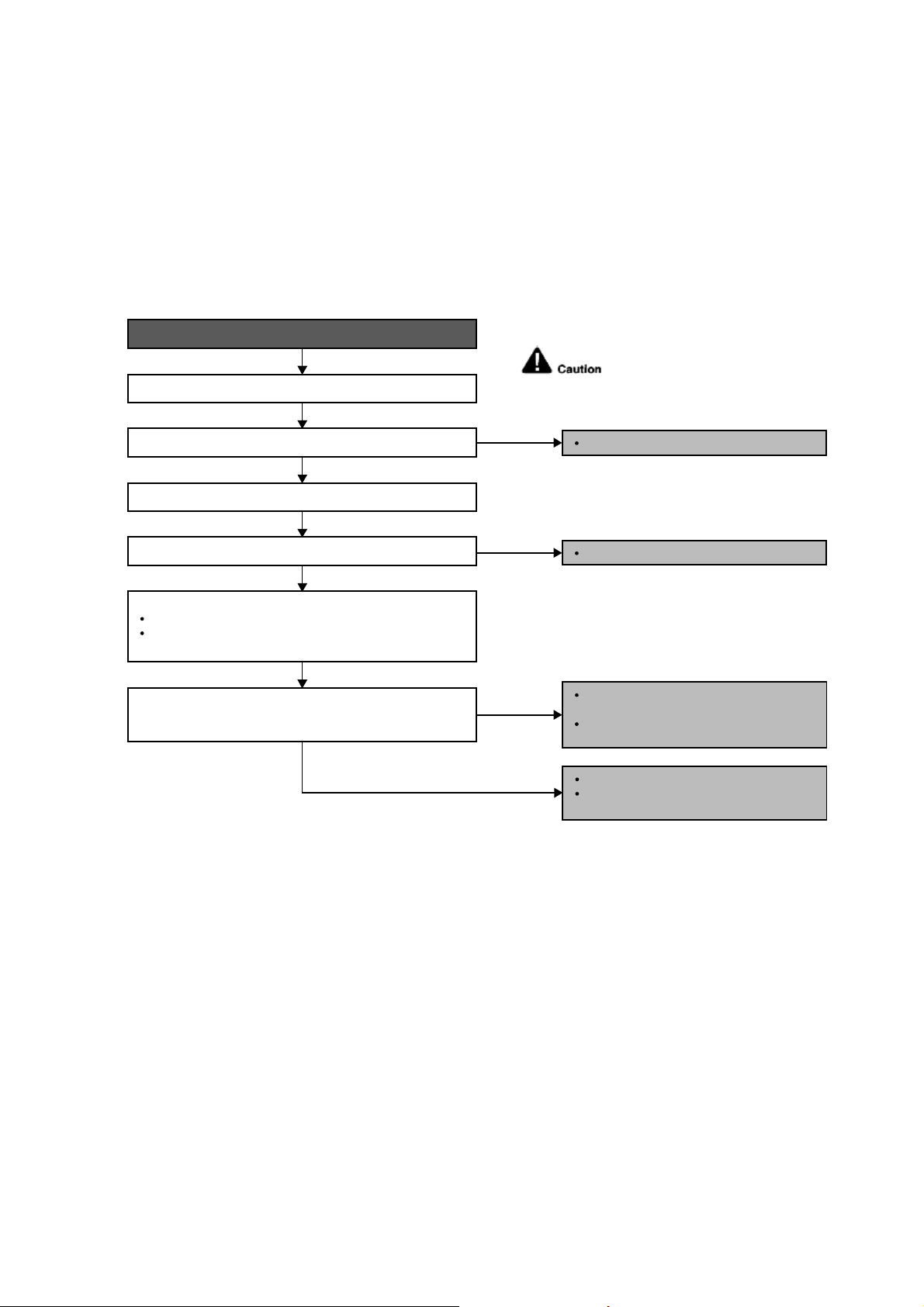
55
12.4.19 H98 (Error Code Stored in Memory and no alarm is triggered / no TIMER LED
flashing)
Malfunction Decision Conditions
Indoor high pressure is detected when indoor heat exchanger is detecting very high temperature when the unit is
operating in heating operation.
Phenomena: unit is stopping and re-starting very often in heating mode.
Malfunction Caused
Indoor heat exchanger thermistor.
Clogged air filter or heat exchanger.
Over-bent pipe (liquid side).
Troubleshooting
Is the measured resistance of the indoor pipe temperature
thermistor matches the value specified in its characteristic
chart?
Check the indoor unit intake air filter.
When abnormality indication starts again.
For safety reason and to prevent
component breakdown, always switch
off the power before remove and
connect the component.
YES
NO
NO
NO
YES
Check the indoor pipe temperature thermistor:
Plug out connector (CN-TH) from the indoor unit PCB.
Measure the resistance of the indoor heat exchanger
temperature thermistor.
Is the air filter dirty?
Check the dust accumulation on the indoor unit heat exchanger.
Is the indoor unit heat exchanger dirty?
Clean the air filter.
Check the piping & installation condition.
Replace piping / reinstall the unit if
necessary.
Defect in indoor pipe temperature
thermistor.
Replace the indoor pipe temperature
thermistor.
YES
Clean the indoor unit heat exchanger.
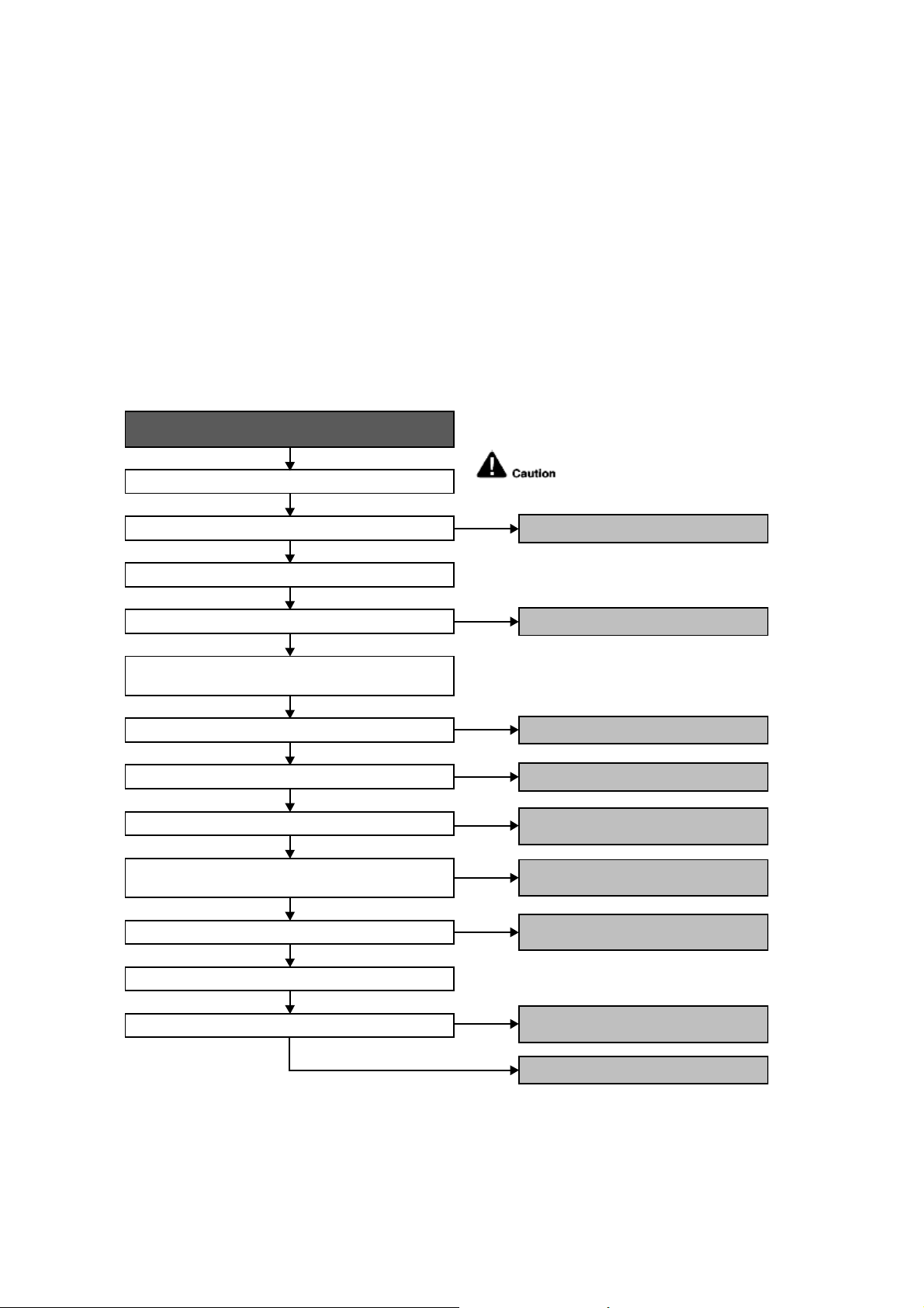
56
12.4.20 H99 (Indoor Freeze Prevention Protection: Cooling or Soft Dry)
Error Code will not display (no Timer LED blinking) but store in EEPROM
Malfunction Decision Conditions
Freeze prevention control takes place (when indoor pipe temperature is lower than 2°C).
Malfunction Caused
Air short circuit at indoor unit.
Clogged indoor unit air filter.
Dust accumulation on the indoor unit heat exchanger.
2/3 way valve closed.
Faulty indoor unit fan motor.
Refrigerant shortage (refrigerant leakage).
Clogged expansion valve or strainer.
Faulty indoor pipe temperature sensor.
Faulty indoor unit PCB.
Troubleshooting
Check the air passage.
When abnormality indication starts again.
For safety reason and to prevent
component breakdown, always switch
off the power before remove and
connect the component.
Is there any short circuit?
YES
YES
YES
YES
YES
YES
YES
NO
NO
Check the indoor unit air filter.
Is the air filter dirty?
Is the indoor unit heat exchanger dirty?
Check if 2/3 way valve is closed?
Check if indoor fan motor operates normally?
Check if expansion valve or strainer clogged (ice formed)?
Does it conform to the sensor characteristic chart?
Check the indoor pipe temperature sensor.
Check the dust accumulation on the indoor unit heat
exchanger.
Check for gas leakage, Is oil oozing out from the 2/3 way
valve?
● Provide sufficient air passage.
● Clean the air filter.
● Clean the indoor unit heat exchanger.
● Open the 2/3 way valve.
● Replace the indoor unit PCB.
● Replace the indoor pipe temperature
sensor.
● Reclaim and recharge with correct
amount of refrigerant.
● Replace the indoor unit fan motor and/or
indoor unit PCB.
● Repair the pipe flare or union nuts.
● Reclaim and recharge refrigerant.
NO
NO
NO
NO
YES
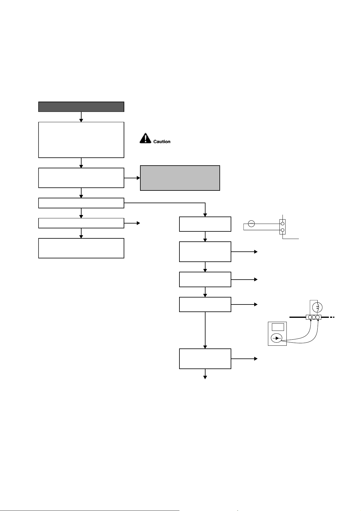
57
12.4.21 F11 (4-way Valve Switching Failure)
Malfunction Decision Conditions
When indoor heat exchanger is cold during heating (except deice) or when indoor heat exchanger is hot during
cooling and compressor operating, the 4-way valve is detected as malfunction.
Malfunction Caused
Indoor heat exchanger (pipe) thermistor
4-way valve malfunction
Troubleshooting
* Check gas side pipe – for hot gas flow in cooling mode
1 2 3
CN-HOT
(VH3-2)
4WAYS
VALVE
For safety reason and to prevent component
breakdown, always switch off the power before
remove and connect the component.
When abnormality starts again.
Problem occurs in heating mode only?
4-way valve not working
(not energize).
Check V-coil attach to
solenoid valve.
Check valve v-coil
continuity.
Check CN-HOT
connection
(4-way valve connector).
Measure voltage
supplied to CN-HOT at
the start of heating.
Check the indoor pipe temperature
thermistor:
● Plug out connector (CN-TH) from the
indoor unit PCB.
● Measure the resisitance of the indoor
heat exchanger temperature thermistor.
● Defect in indoor pipe temperature
thermistor.
● Replace the indoor pipe temperature
thermistor.
Outdoor PCB fault
● Replace Outdoor PCB.
Reverse solenoid value faulty
● Replace the 4-way valve.
● Reconnect CN-HOT
(4-way valve connector).
V-coil fault
● Replace
V-coil only.
● Attach and screw the V-coil
to solenoid valve.
Remove CN-HOT.
Measure continuity
of the coil.
Outdoor PCB fault
● Replace
Outdoor PCB.
No supply.
OK
OK (Depending on 4-way valve model).
OK
OK
YES
No
Good.
4 WAYS VALVE
COIL COMPLETE
YELLOW
YELLOW
CN-HOT
(WHT)
1
2
No
Good.
No
continuity
(open).
YES
YES
NO
NO
NO, it happen in cooling/dry as well.
● Check connecting tubes to 4-way valve.
Is the measured resistance of the indoor pipe
temperature thermistor matches the value
specified in its characteristic chart?
The 4-way valve may have been damaged or
wrongly connected between discharge and
suction tube.
Is 4-way solenoid valve being energised?
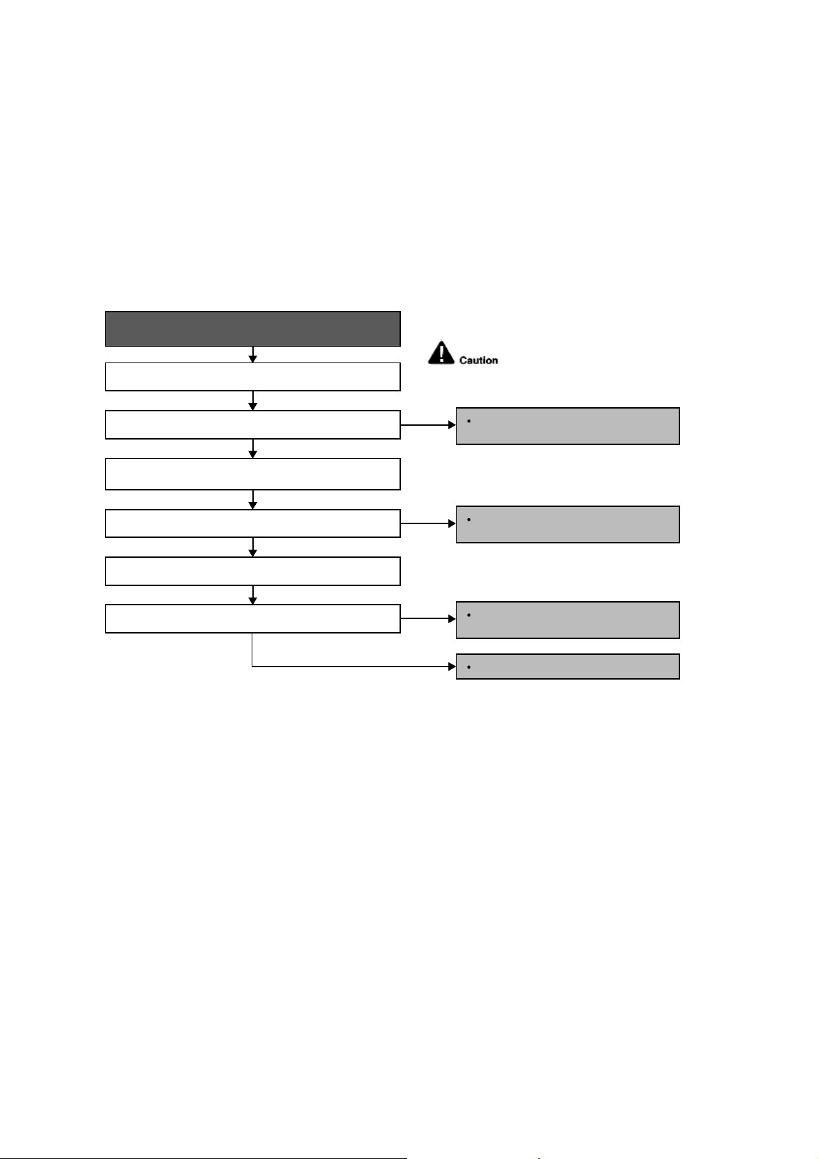
58
12.4.22 F17 (Indoor Standby Units Freezing Abnormality)
Malfunction Decision Conditions
When the different between indoor intake air temperature and indoor pipe temperature is above 50°F or indoor
pipe temperature is below 30.2°F
Remark:
When the indoor standby unit is freezing, the outdoor unit transfers F17 error code to the corresponding indoor
unit and H39 to other indoor unit(s).
Malfunction Caused
Wrong wiring connection
Faulty sensor
Faulty expansion valve
Troubleshooting
When F17 indication happens.
For safety reason and to prevent
component breakdown, always switch
off the power before remove and
connect the component.
Check the system wiring connection.
YES
YES
NO
Is the wiring connection ok?
Perform Auto Wiring to correct the wiring
connection.
NO
Replace the indoor intake air or indoor
pipe temperature sensor.
NO
Replace the solenoid coil or expansion
valve.
Replace outdoor unit PCB.
YES
Does it conform to the sensor characteristic chart?
Check the expansion valve.
Is the expansion valve ok?
Check the indoor intake air and indoor pipe temperature
sensors.
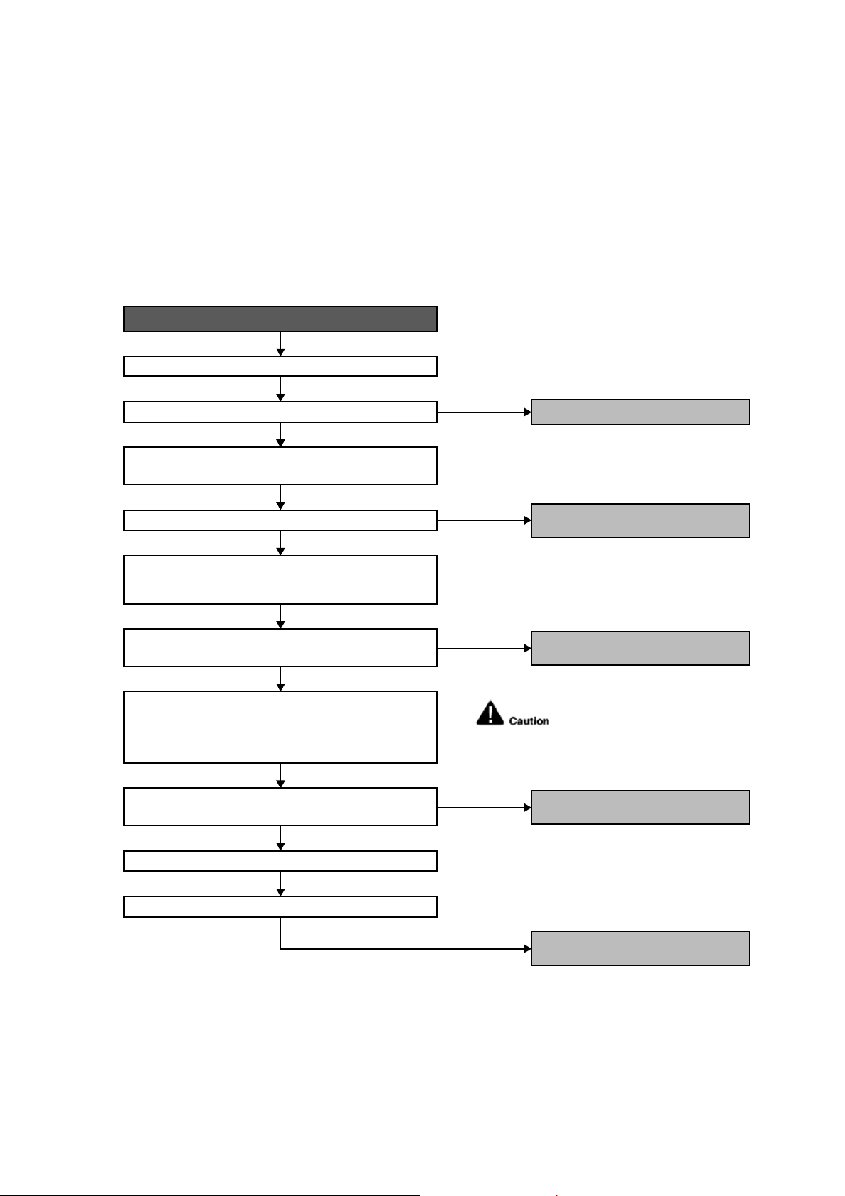
59
12.4.23 F90 (Power Factor Correction Protection)
Malfunction Decision Conditions
To maintain DC voltage level supply to power transistor.
To detect high DC voltage level after rectification.
Malfunction Caused
During startup and operation of cooling and heating, when Power Factor Correction (PFC) protection circuitry at
the outdoor unit main PCB senses abnormal DC voltage level for power transistors.
When DC voltage detected is LOW, transistor switching will turn ON by controller to push-up the DC level.
When DC voltage detected is HIGH (391Vdc – 425Vdc), active LOW signal will send by the controller to turn OFF
relay RY-C.
Troubleshooting
When abnormality indication starts again.
Reset the error code and turn on the unit again.
Is AC power supply normal fluctuation?
Verify PFC abnormality by measuring DC voltage between
DCP(+) and DCN(-) at the capacitor PCB.
Is the DC voltage between DCP(+) and DCN(-) normal?
Check the reactor impedance.
Is the impedence of the reactor low?
Is the DC voltage between CN-FM1 and 4 of the outdoor fan
motor normal?
Are the compressor’s winding resistance (U-V, V-W, U-W)
uniform?
Confirm the DC voltage between CN-FM 1 and 4 when
compressor is running. Normal voltage range should be
between 265-325Vdc.
NO
YES
YES
YES
NO (391.2Vdc ~ 425Vdc)
● AC power supply abnormal surge.
YES (~280Vdc)
● Defect in PFC circuitry.
● Replace the outdoor unit PCB.
NO
● Defect in outdoor fan motor.
● Replace outdoor fan motor.
NO
● Defect in compressor.
● Replace compressor.
● Defect in reactor.
● Replace reactor.
For safety reason and to prevent
component breakdown, always
switch off the power before remove
and connect the component.
Check the compressor winding resistance:
● Turn off the power and disconnect the harnesses U, V,
and W.
● Measure the winding resistance between U-V, V-W, and
W-U.
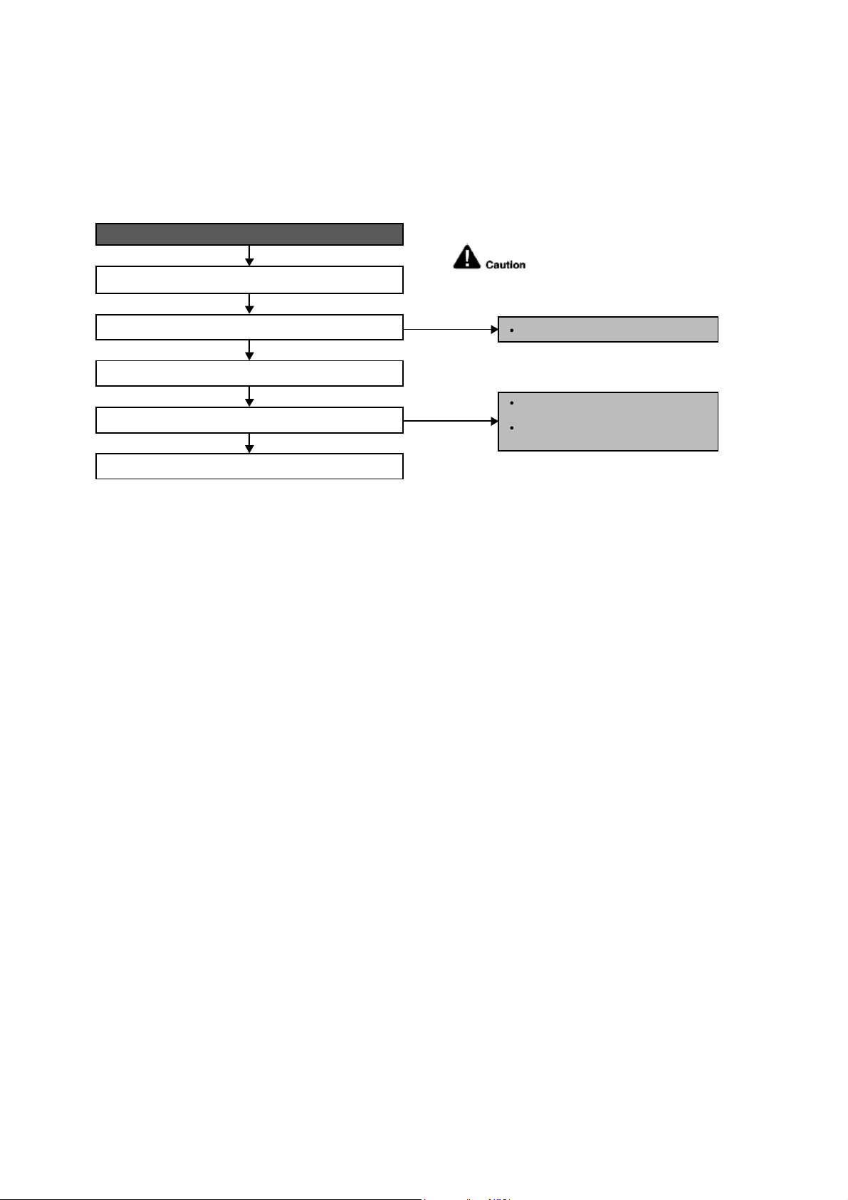
60
12.4.24 F91 (Refrigeration Cycle Abnormality)
Malfunction Decision Conditions
The input current is low while the compressor is running at higher than the setting frequency.
Malfunction Caused
Lack of gas.
3-way valve close.
Troubleshooting
When F91 indication happens.
For safety reason and to prevent
component breakdown, always switch
off the power before remove and
connect the component.
Open 3 way valve.
NO, closed.
NO, gas amount is OK.
Check 3 way valve.
3-way valve opened?
Check for gas leaking source (Refer H16).
Gas leaking?
Check other parts in refrigeration cycles.
Check for gas leaking source;
Repair or replace defected part(s).
Re-claim and then re-charge the
right amount.
YES
YES
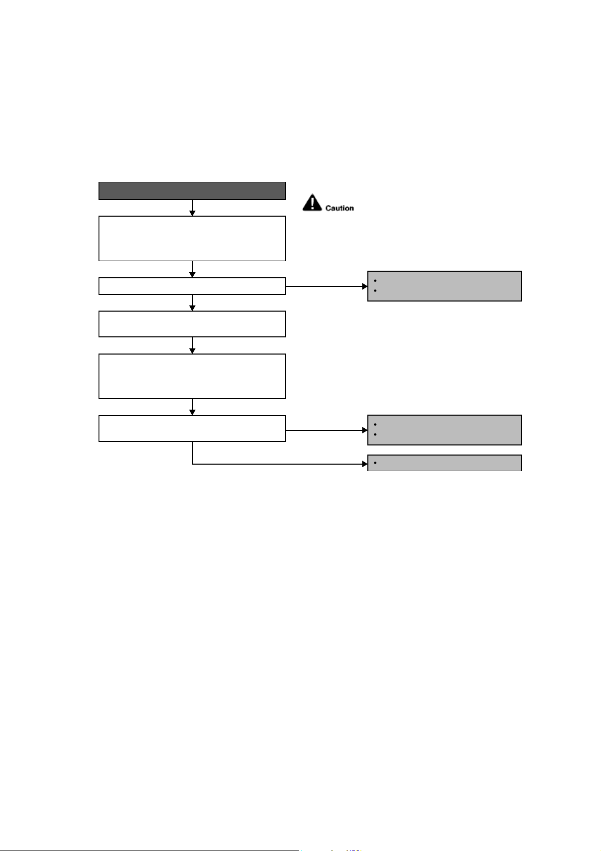
61
12.4.25 F93 (Compressor Rotation Failure)
Malfunction Decision Conditions
A compressor rotation failure is detected by checking the compressor running condition through the position
detection circuit.
Malfunction Caused
Compressor terminal disconnect.
Faulty Outdoor PCB.
Faulty compressor.
Troubleshooting
When F93 indication happens.
Check the U, V and W connector connection:
-TurnOFFthepower.
- Check the U, V and W connector connection at
outdoor PCB and compressor terminal.
NO
From the disconnected harnesses U, V and W,
correct them to the inverter checker. Turn ON the
power and operate the system. Check the inverter
checker 6 LEDs blinking condition.
Disconnect the harnesses U, V and W from the
compressor terminal.
Is the blinking of the 6 LEDs in same
sequence/condition.
Is the connector connection normal?
For safety reason and to prevent
component breakdown, always
switch off the power before remove
and connect the component.
Correct the connection.
Connector poor contact.
NO
YES
YES
Replace outdoor unit PCB.
IPM defective.
Replace compressor.
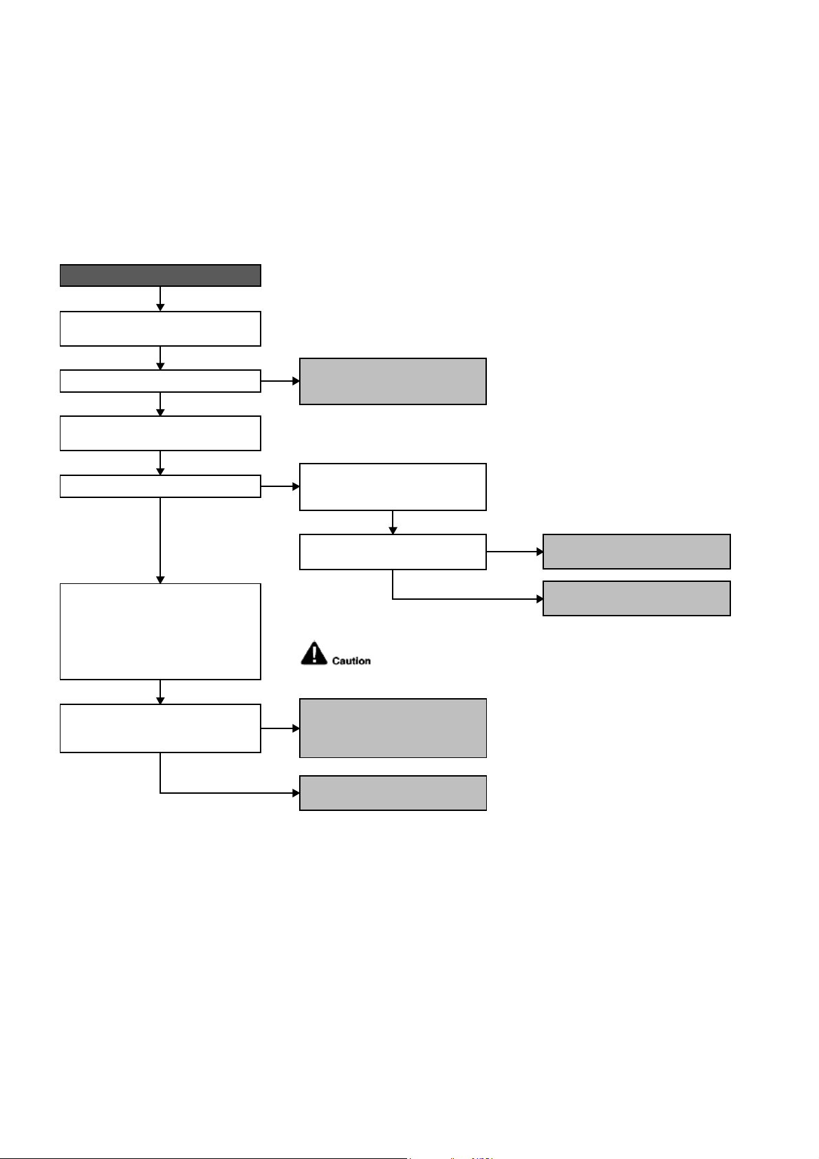
62
12.4.26 F95 (Outdoor High Pressure Protection: Cooling or Soft Dry)
Malfunction Decision Conditions
During operation of cooling or soft dry, when outdoor unit heat exchanger high temperature data is detected by
the outdoor unit heat exchanger thermistor.
Malfunction Caused
Outdoor heat exchanger temperature rise due to short-circuit of hot discharge air flow.
Outdoor heat exchanger temperature rise due to defective of outdoor fan motor.
Outdoor heat exchanger temperature rise due to defective outdoor heat exchanger thermistor.
Outdoor heat exchanger temperature rise due to defective of outdoor unit PCB.
Troubleshooting
For safety reason and to prevent component
breakdown, always switch off the power
before remove and connect the component.
When abnormality indication starts again.
Is there any improper heat radiation?
Is the outdoor fan motor operating?
Check the outdoor unit installation condition
(during cooling or soft dry operation).
Is the measured resistance of the outdoor
heat exchanger thermistor matches the
value specified in its characteristic chart?
Reset the error code and turn on the unit
again.
Check the outdoor heat exchanger
thermistor:
● Turn off the power and disconnect the
connector of outdoor heat exchanger
thermistor from the PCB.
● Measure the resistance of the outdoor
heat exchanger thermistor.
● Reinstall the outdoor unit.
● Remove the obstacle(s).
● Clean the outdoor heat exchanger.
Measure the AC/DC voltage between
pins of connector CN-FM outdoor unit
PCB.
Is the voltage supplied to the outdoor
fan motor normal?
● Defect in outdoor unit PCB.
● Replace the outdoor unit PCB.
● Defect in outdoor unit PCB.
● Replace the outdoor unit PCB.
● Defect in outdoor heat exchanger
thermistor.
● Replace the outdoor heat exchanger
thermistor.
● Defect in outdoor fan motor.
● Replace the outdoor fan motor.
NO
NO
NO
YES
NO (0V)
YES (240VAC / 265~326VDC)
YES
YES
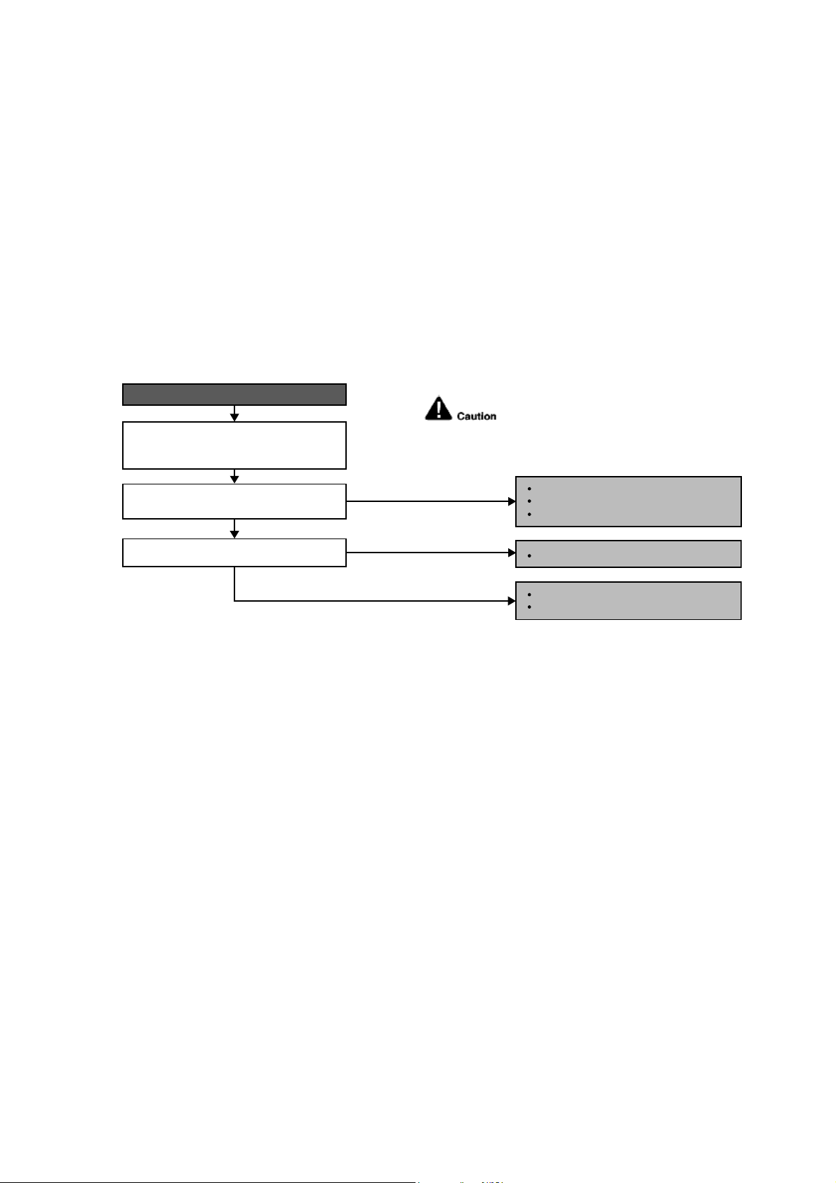
63
12.4.27 F96 (IPM Overheating)
Malfunction Decision Conditions
During operating of cooling and heating, when IPM temperature data (212°F) is detected by the IPM temperature
sensor.
Multi Models only
o Compressor Overheating: During operation of cooling and heating, when the compressor OL is activated.
o Heat Sink Overheating: During operation of cooling and heating, when heat sink temperature data (194°F) is
detected by the heat sink temperature sensor.
Malfunction Caused
IPM overheats due to short circuit of hot discharge air flow.
IPM overheats due to defective of outdoor fan motor.
IPM overheats due to defective of internal circuitry of IPM.
IPM overheats due to defective IPM temperature sensor.
Multi Models Only
o Compressor OL connector poor contact.
o Compressor OL faulty.
Troubleshooting
When F96 indication happens.
For safety reason and to prevent component
breakdown, always switch off the power
before remove and connect the component.
Check the outdoor unit installation
condition (during cooling or soft-dry
operation).
Is there any improper heat radiation?
YES
YES
NO
NO
Reinstall the outdoor unit.
Replace the outdoor fan motor.
Remove the obstacle(s).
Clean the outdoor heat exchanger.
Defect in IPM.
Replace the outdoor unit PCB.
Is outdoor fan motor operating?
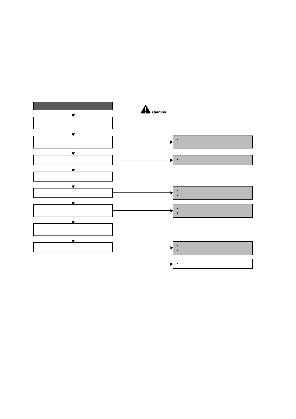
64
12.4.28 F97 (Compress or Overheating)
Malfunction Decision Conditions
During operation of cooling and heating, when compressor tank temperature data (233.6°F) is detected by the
compressor tank temperature sensor.
Malfunction Caused
Faulty compressor tank temperature sensor
2/3 way valve closed
Refrigerant shortage (refrigerant leakage)
Faulty outdoor unit PCB
Faulty compressor
Troubleshooting
When F97 indication happens.
For safety reason and to prevent component
breakdown, always switch off the power
before remove and connect the component.
Replace the compressor tank
temperature sensor.
Repair the pipe flare or union nuts.
Reclaim and recharge refrigerant.
Open the 2/3 way valve.
Procedure complete.
Check the compressor tank temperature
sensor.
Does it conform to the sensor
characteristic chart?
Check if expansion valve or strainer
clogged (ice formed).
Reclaim and recharge for a specified
amount of refrigerant.
2/3 way valve closed?
Check for gas leakage.
Oil oozing out from the 2/3 way valve?
Refrigerant cycle abnormality error again?
YES
YES
YES
NO
NO
NO
NO
NO
Replace expansion valve and/or strainer.
Reclaim and recharge refrigerant.
YES
Replace outdoor unit PCB.
Replace outdoor unit compressor.
YES
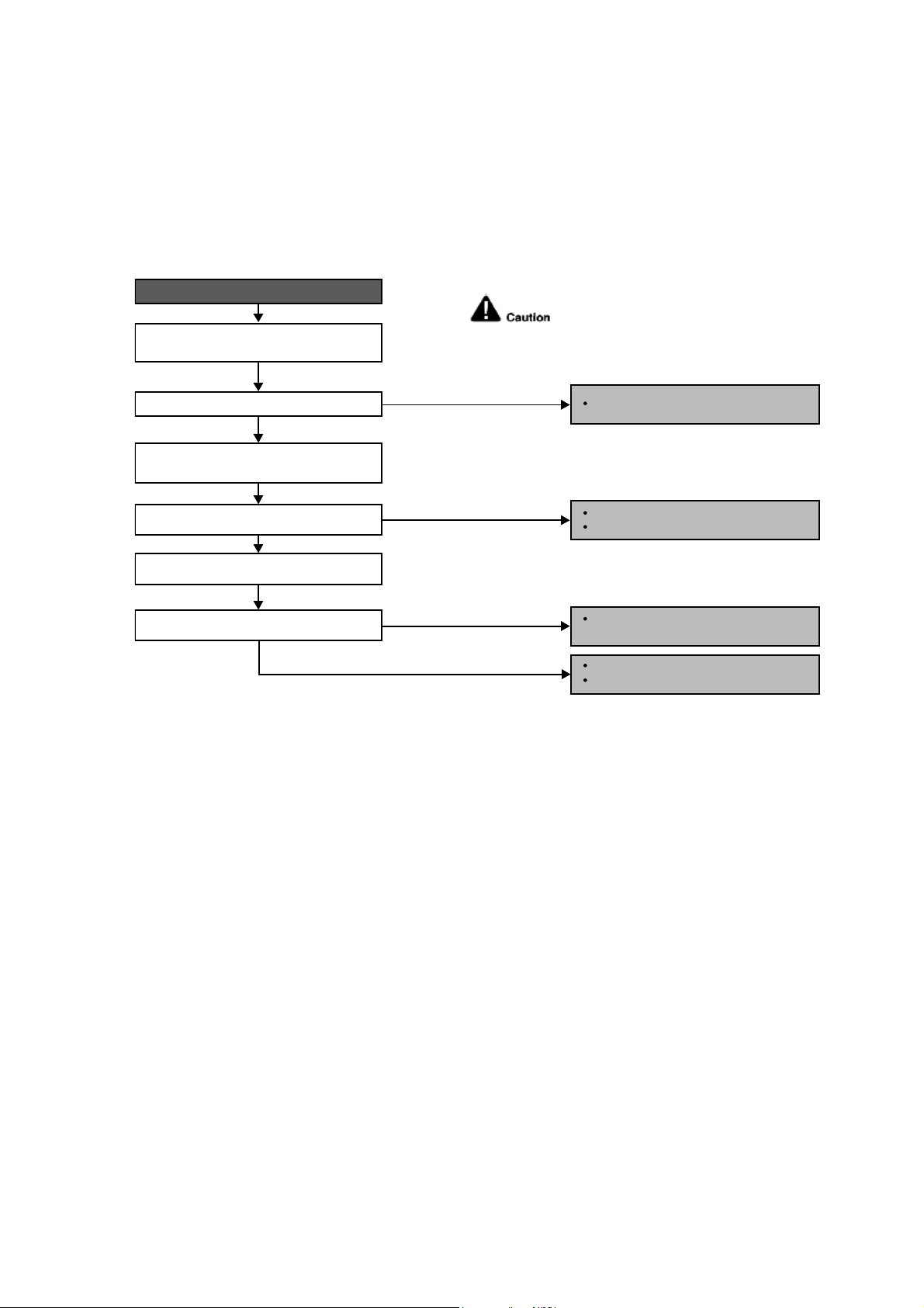
65
12.4.29 F98 (Input Over Current Detection)
Malfunction Decision Conditions
During operation of cooling and heating, when an input over-current (X value in Total Running Current Control) is
detected by checking the input current value being detected by current transformer (CT) with the compressor
running.
Malfunction Caused
Excessive refrigerant.
Faulty outdoor unit PCB.
Troubleshooting
For safety reason and to prevent component
breakdown, always switch off the power
before remove and connect the component.
Replace the outdoor unit PCB.
Repair the pipe flare or union nuts.
Reclaim and recharge refrigerant.
Reclaim and recharge with correct
amount of refrigerant.
Replace outdoor unit PCB.
Replace outdoor unit compressor.
When F98 indication happens.
Get restarted and measure the input
current.
Turn off power supply. Check the main
circuit electrolytic capacitor.
Input current > limit?
Normal?
Check refrigerant amount.
Excess refrigerant?
YES
YES
YES
NO
NO
NO
NO
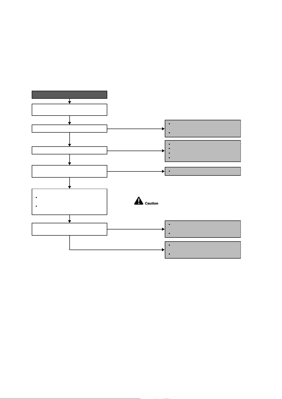
66
12.4.30 F99 (DC Peak Detection)
Malfunction Decision Conditions
During startup and operation of cooling and heating, when inverter DC peak data is received by the outdoor internal
DC Peak sensing circuitry.
Malfunction Caused
DC current peak due to compressor failure.
DC current peak due to defective power transistor(s).
DC current peak due to defective outdoor unit PCB.
DC current peak due to short circuit.
Troubleshooting
For safety reason and to prevent component
breakdown, always switch off the power
before remove and connect the component.
Outdoor electronic circuit defect due to
power transistor short.
Excessive amount of refrigerant.
Replace the outdoor unit PCB.
Compressor defective due to
mechanical locked.
Replace compressor.
Compressor defective due to winding
shorted.
Replace compressor.
Amplification IC defect.
Diode defect.
Defect in microcontroller.
Replace the outdoor unit PCB.
When abnormality indication starts again.
Reset the error code and turn on the unit
again.
Is there no change even if all refrigerant
is discharged?
Are the compressor’s winding resistance
(U-V, V-W or U-W) shorted?
Is there a sound when compressor starts?
Is compressor vibration even?
YES
YES
YES
Turn off the power and disconnect
the harnesses U, V and W.
Measure the winding resistance
between U-V, V-W and W-U.
Check the compressor winding resistance:
NO (Compressor stops)
NO (Normal)
NO (Normal)
NO (Quite a lot of vibration at
start operation)
YES (Stops after 2, 3 seconds
of noise during operation)
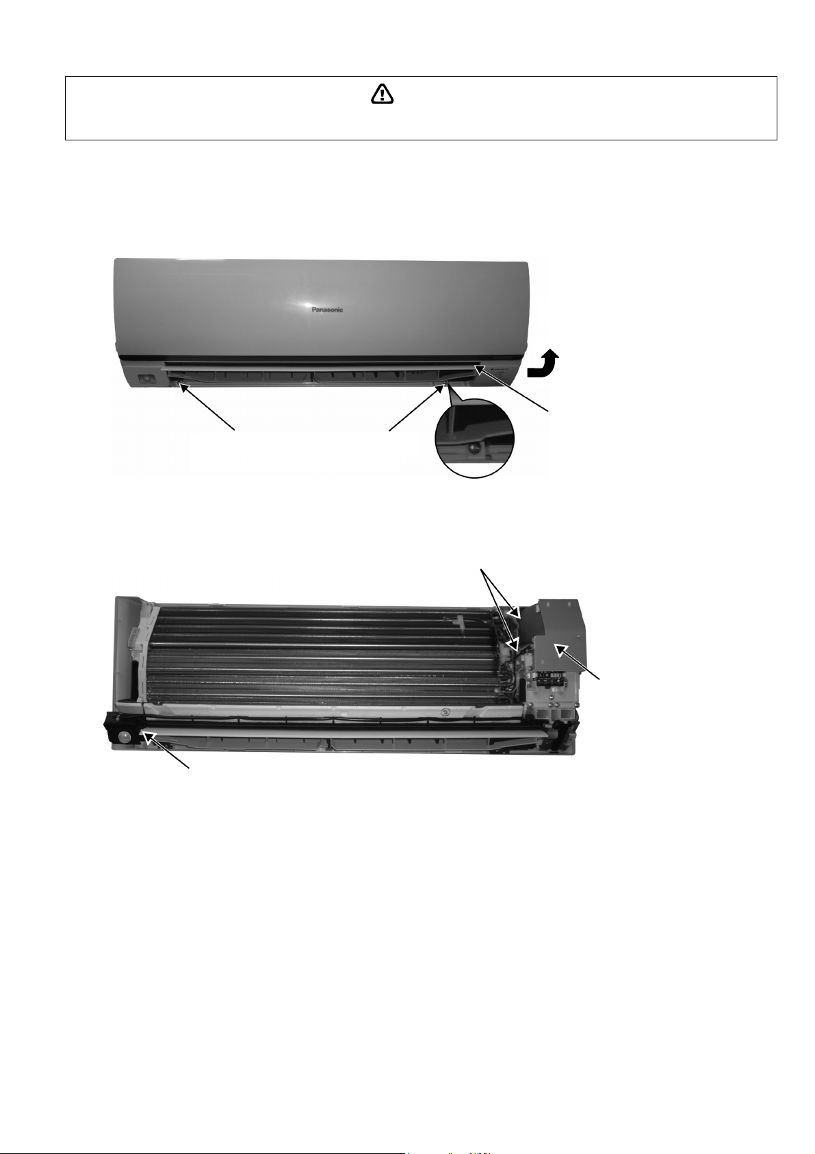
67
WARNING
13. Disassembly and Assembly Instructions
High Voltage is generated in the electrical parts area by the capacitor. Ensure that the capacitor has discharged sufficiently before proceeding with
repair work. Failure to heed this caution may result in electric shocks.
13.1 Indoor Electronic Controllers, Cross Flow Fan and Indoor Fan Motor
Removal Procedures
13.1.1 To remove front grille
Figure 1
13.1.2 To remove power electronic controller
Figure 2
2. Remove 2 caps and 2 screws at the
bottom of discharge vane.
3. Hold both sides of the front grille and
remove it by pulling up and toward
yourself gently.
1. Lift to open the vertical vane
gently.
5. Remove the control
board cover by releasing
the 2 hooks.
4. Remove the eco sensor complete by screw.
2 Hooks (left hand side)
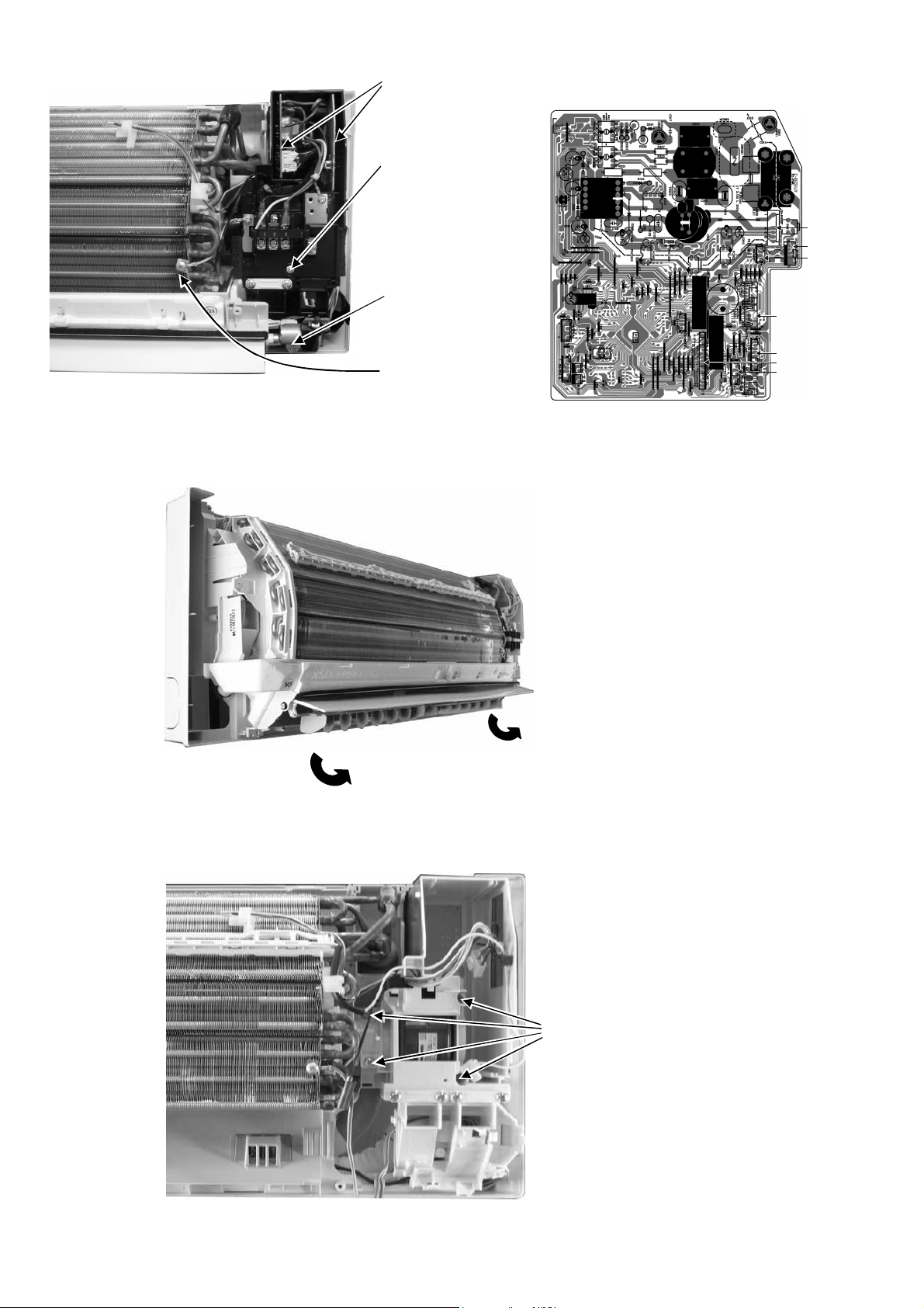
68
Figure 3 Figure 4
13.1.3 To remove discharge grille
Figure 5
13.1.4 To remove control board
Figure 6
CN-RMT
CN-FM
CN-CNT
CN-STM1
CN-MSENS
CN-TH
CN-DISP
7. Detach the CN-DISP
connector then remove
the indicator complete.
10. Detach connectors as labeled from the
electronic controller. Then pull out
main controller gently
9. Pull out the main
electronic controller and
power electronic
controller halfway.
8. Remove screw to
remove terminal board
complete.
6. Detach the Earth wire
11. Pull out to remove the drain hose
from the discharge grille
12. Then pull the discharge grille
downward gently to dismantle it
13. Remove 4 screws holding the
control board then pull out the
control board.
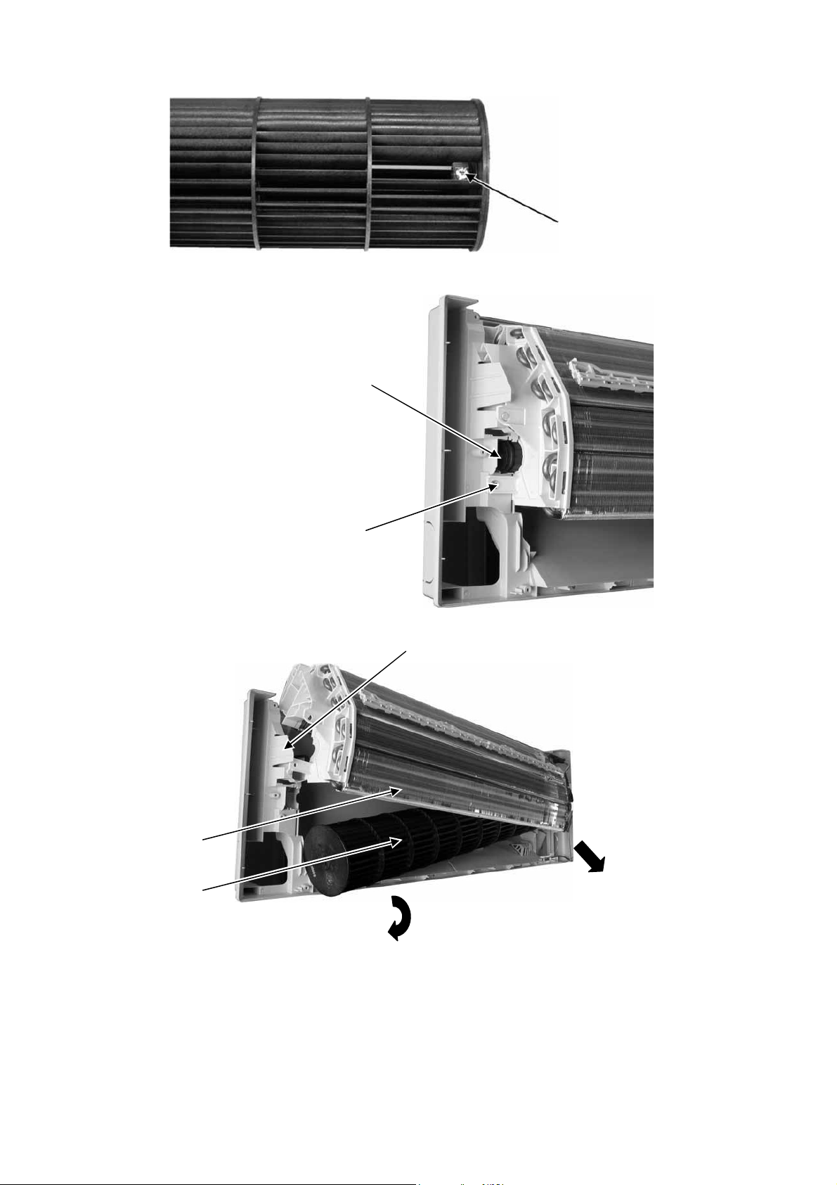
69
13.1.5 To remove cross flow fan and indoor fan motor
Figure 7
Figure 8
Figure 9
14. Remove the screw that holding
the cross flow fan and fan motor
axis.
16. Remove the bearing by pulling it
out gently
15. Remove the screw from the
evaporator.
17. Push the holdfast to the left and lift up the evaporator.
19. Fan motor can be removed after the
removal of cross flow fan.
Reminder: To reinstall the fan motor, adjust
the fan motor connector to 45° towards you
before fixing control board.
18. Remove the cross flow fan from the unit by
pulling it to the left and downward.
Evaporator
Cross flow fan
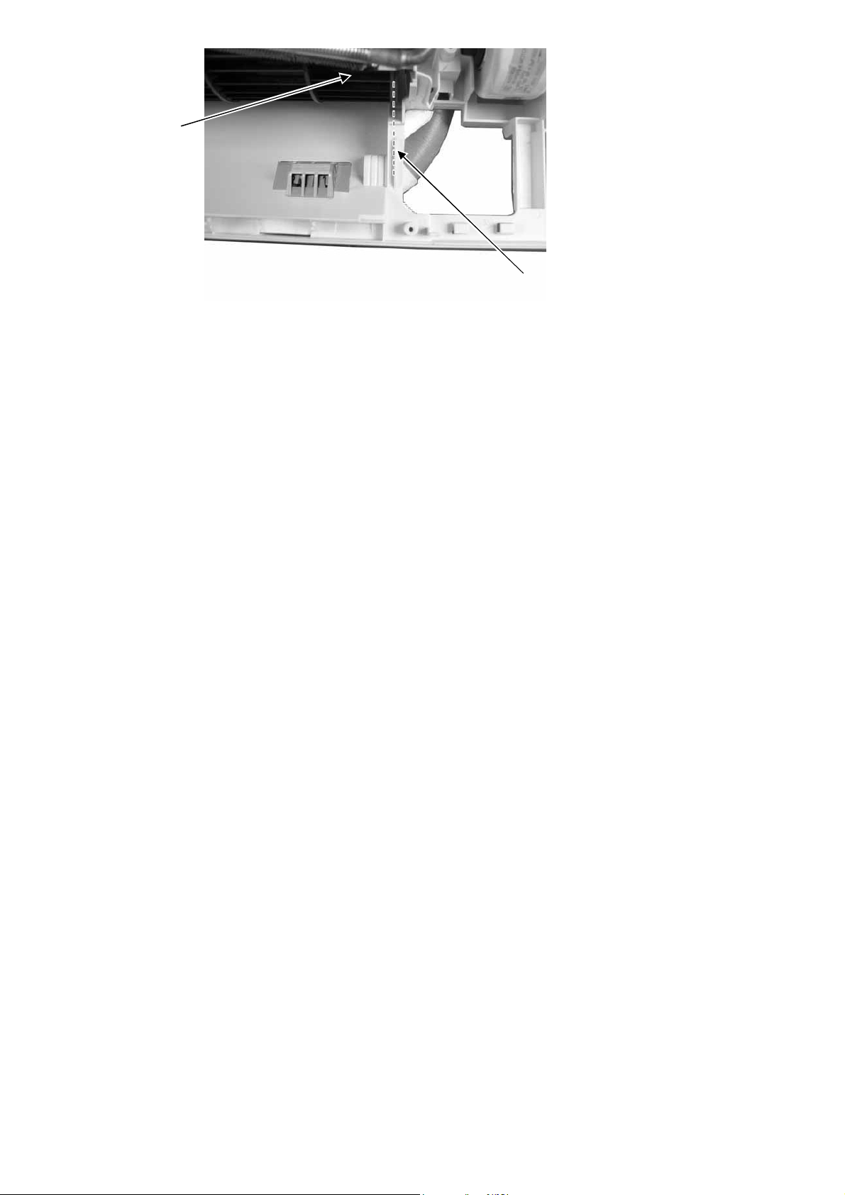
70
Figure 10
Reminder: To reinstall the cross flow
fan, ensure cross flow fan is in line as
shown in figure 10
Cross Flow Fan
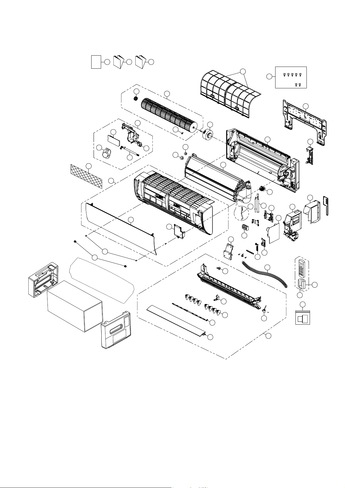
71
14. Exploded View and Replacement Parts List
14.1 Indoor Unit
Note
The above exploded view is for the purpose of parts disassembly and replacement.
The non-numbered parts are not kept as standard service parts.
I/I I/I
O/I
CWH55025J
CWH55051J
12
24
15
36
55
33
45
46 47 48
40
44
3
4
2
5
1
27
23
11
16
26
34
28
29
30
39
9
37
35
10
7
38
8
41
42
43
13
14
6
25
21
54
22
18
17
20
49
72
SAFETY REF. NO. DESCRIPTION & NAME QTY CS-ME5RKUA REMARK
1 CHASSIS COMPLETE 1 CWD50C1633
2 FAN MOTOR 1 L6CBYYYL0055 O
3 CROSS FLOW FAN COMPLETE 1 CWH02C1076
4 BEARING 1 CWH64K007
5 SCREW 1 CWH551146
7 EVAPORATOR CO. 1 CWB30C3504
8 FLARE NUT (1/4) - LIQUID 1 CWT251030
9 FLARE NUT (3/8) - GAS 1 CWT251031
11 CONTROL BOARD CASING 1 CWH102605A
12 TERMINAL BOARD COMPLETE 1 CWA28C2357
13 ELECTRONIC CONTROLLER - MAIN 1 CWA73C9301 O
15 ELECTRONIC CONTROLER - INDICATOR 1 CWA748158 O
16 SENSOR COMPLETE 1 CWA50C2800 O
17 SENSOR COMPLETE (ECO) 1 CWA50C2820 O
18 ELECTRONIC CONT (ECO SENSOR) 1 CWA745791
20 ELECTRONIC CONT (COMPARATOR) 1 CWA746769
21 LEADWIRE-PCB ECO 1 CWA67C9786
23 CONTROL BOARD TOP COVER 1 CWH131467
24 INDICATOR HOLDER 1 CWD933406
25 CONTROL BOARD FRONT COVER CO. 1 CWH13C1333
26 DISCHARGE GRILLE COMPLETE 1 CWE20C3495
27 BACK COVER CHASSIS 1 CWD933233B
28 FULCRUM 1 CWH621131
29 VERTICAL VANE 8 CWE241374
30 CONNECTING BAR 1 CWE261251
33 AIR SWING MOTOR 1 CWA981264 O
34 CAP 1 CWH521096
35 HORIZONTAL VANE COMPLETE 1 CWE24C1385
36 REMOTE CONTROL COMPLETE 1 CWA75C4567 O
37 FRONT GRILLE COMPLETE 1 CWE11C5960 O
38 INTAKE GRILLE COMPLETE 1 CWE22C1946
39 GRILLE DOOR COMPLETE 1 CWE14C1131
40 AIR FILTER 2 CWD001279 O
41 SCREW-F/GRILLE MOUNT 2 XTT4+16CFJ
42 CAP-FRONT GRILLE 2 CWH521227
43 DRAIN HOSE 1 CWH851173
44 INSTALLATION PLATE 1 CWH361134
45 BAG COMPLETE - INSTALLATION SCREW 1 CWH82C1705
46 OPERATING INSTRUCTION 1 CWF569978
47 INSTALLATION INSTRUCTION 1 CWF616708
48 INSTALLATION INSTRUCTION 1 CWF616709
49 REMOTE CONTROL HOLDER 1 CWH361078
54 AIR PURIFYING FILTER 1 CWD00C1141
55 BAG COMPLETE (TUBE CONNECTOR) 1 CWH82C2030
(Note)
All parts are supplied from PHAAM, Malaysia (Vendor Code: 00029488).
“O” marked parts are recommended to be kept in stock.
73
SAFETY REF. NO. PART NAME & DESCRIPTION QTY. CS-ME7RKUA REMARK
1 CHASSIS COMPLETE 1 CWD50C1633
2 FAN MOTOR 1 L6CBYYYL0055 O
3 CROSS-FLOW FAN COMPLETE 1 CWH02C1076
4 BEARING ASSY 1 CWH64K007
5 SCREW - CROSS - FLOW FAN 1 CWH551146
6 PARTICULAR PIECE 1 CWD933067
7 EVAPORATOR 1 CWB30C5033
8 FLARE NUT (LIQUID) 1 CWT251030
9 FLARE NUT (GAS) 1 CWT251031
10 CLIP FOR SENSOR 1 CWH321085
11 CONTROL BOARD CASING 1 CWH102605A
12 TERMINAL BOARD COMPLETE 1 CWA28C2357 O
13 ELECTRONIC CONTROLLER - MAIN 1 CWA73C9225 O
14 PARTICULAR PIECE - TERMINAL 1 CWD933137A
15 ELECTRONIC CONTROLLER - INDICATOR 1 CWA748158 O
16 SENSOR COMPLETE 1 CWA50C3228 O
17 SENSOR COMPLETE (ECO) 1 CWA50C2820 O
18 ELECTRONIC CONTROLLER (ECO SENSOR) 1 CWA745791
20 ELECTRONIC CONTROLLER (COMPARATOR) 1 CWA746769
21 LEAD WIRE - PCB ECO 1 CWA67C9786
22 CONTROL BOARD CASING FOR PCB ECO 1 CWD933427
23 CONTROL BOARD TOP COVER 1 CWH131467
24 INDICATOR HOLDER 1 CWD933406
25 CONTROL BOARD FRONT COVER CO. 1 CWH13C1333
26 DISCHARGE GRILLE COMPLETE 1 CWE20C3495
27 BACK COVER CHASSIS 1 CWD933233B
28 FULCRUM 1 CWH621131
29 VERTICAL VANE 8 CWE241374
30 CONNECTING BAR 2 CWE261251
33 AIR SWING MOTOR 1 CWA981264
34 CAP - DRAIN TRAY 1 CWH521259
35 HORIZONTAL VANE COMPLETE 1 CWE24C1385
36 REMOTE CONTROL COMPLETE 1 CWA75C4567 O
37 FRONT GRILLE COMPLETE 1 CWE11C5960 O
38 INTAKE GRILLE COMPLETE 1 CWE22C1946
39 GRILLE DOOR COMPLETE 1 CWE14C1131
40 AIR FILTER 2 CWD001279 O
41 SCREW - FRONT GRILLE 2 XTT4+16CFJ
42 CAP - FRONT GRILLE 2 CWH521227
43 DRAIN HOSE 1 CWH851173
44 INSTALLATION PLATE 1 CWH361134
45 BAG COMPLETE - INSTALLATION SCREW 1 CWH82C1705
46 OPERATING INSTRUCTION 1 CWF569978
47 INSTALLATION INSTRUCTION 1 CWF616708
48 INSTALLATION INSTRUCTION 1 CWF616709
49 REMOTE CONTROL HOLDER 1 CWH361078

74
SAFETY REF. NO. PART NAME & DESCRIPTION QTY. CS-ME7RKUA REMARK
54 AIR PURIFYING FILTER 1 CWD00C1141
55 BAG COMPLETE (TUBE CONNECTOR) 1 CWH82C2030
(Note)
All parts are supplied from PHAAM, Malaysia (Vendor Code: 00029488).
“O” marked parts are recommended to be kept in stock.
Printed in Malaysia
FB0315-0