Operator's Manual
CRAFTSMAN°
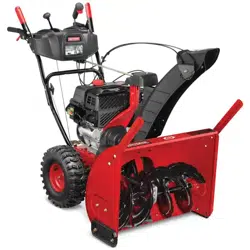
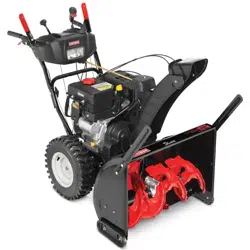
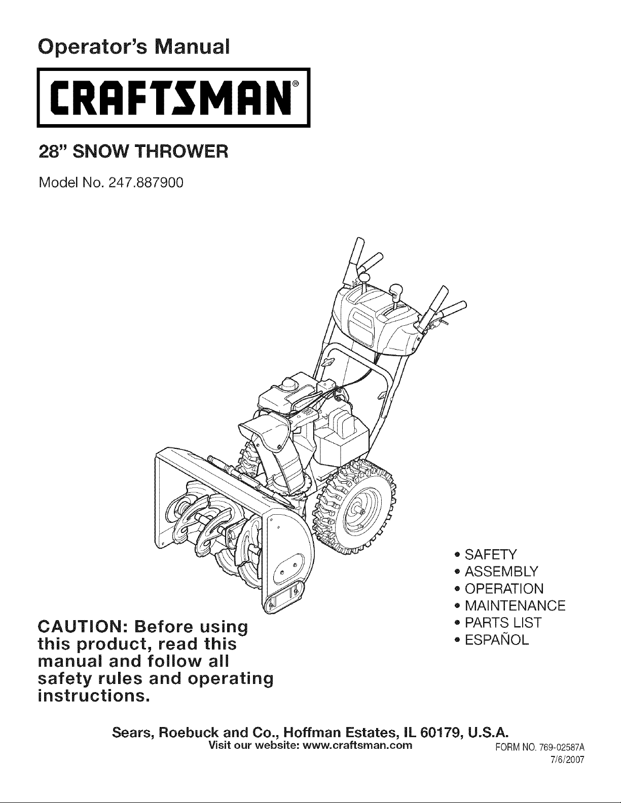
28" SNOW THROWER
Model No. 247.887900
CAUTION: Before using
this product, read this
manual and follow all
safety rules and operating
instructions.
• SAFETY
ASSEMBLY
OPERATION
MAINTENANCE
PARTS LIST
ESPANOL
Sears, Roebuck and Co., Hoffman Estates, IL 60179, U.S.A.
Visit our website: www, craftsrnan.corn FORMNO.769-02587A
7/6/2007
WarrantyStatement..................................Page2
RepairProtectionAgreement...................Page3
SafeOperationPractices.........................Pages4-5
SafetyLabels............................................Page7
Assembly..................................................Pages8-11
Operation..................................................Pages12-15
ServiceandMaintenance.........................Pages16-21
Off-SeasonStorage..................................Page22
TroubleShooting......................................Page23
PartsList...................................................Page24-35
Espa_ol.....................................................Page38
ServiceNumbers......................................BackCover
Two-YearWarranty on Craftsman Snow Thrower
Thisequipmentiscoveredbyatwo-yearwarranty,providedthatitismaintained,lubricated,andtunedupaccordingtotheinstructionsinthe
operator'smanual.Duringthewarrantyyears,ifthisequipmentexperiencesanyfailureduetodefectsinmaterialorworkmanship,RETURNIT
TOYOURNEARESTSEARSPARTS&REPAIRCENTER,andSearswillrepairit,freeofcharge.In-homewarrantyserviceisavailable,butyou
willhavetopayatripcharge.
Thiswarrantydoesnotcover:
• Expendableitemswhichbecomewornduringnormaluse,suchas skid shoes,shaveplate andsparkplugs.
• Repairsnecessarybecauseof operatornegligence,includingbutnot limitedto, electricaland mechanicaldamagecausedby improper
storage,bentcrankshafts,failureto use the propergradeand amountof engineoil, or failureto maintaintheequipmentaccordingto the
instructionscontainedin the operator'smanual.
• Engine(fuelsystem)cleaningorrepairscausedbyfuel determinedto becontaminatedor oxidized(stale). Ingeneral,fuel shouldbe used
within30 daysof itspurchasedate.
• Equipmentif usedfor commercialorrentalpurposes.
Thiswarrantyappliesforonly 90 daysif this productis everusedfor commercialor rentalpurposes.
This warrantyappliesonly whilethis productis usedin the UnitedStates.
This warrantygivesyouspecific legal rights,andyou may alsohaveotherrightswhichvaryfromstateto state.
Sears, Roebuck and Co., Hoffman Estates, IL 60179
EngineOil Type: SAE5W-30
EngineOil Capacity: 26 ounces
FuelCapacity: 4 Quarts
SparkPlug: Champion@RJ19LM
SparkPlugGap: .030"
Model Number.................................................................
Serial Number .................................................................
Dateof Purchase.............................................................
Recordthe modelnumber,serialnumber
anddateof purchaseabove
© Sears Brands,LLC
Congratulationson makingasmartpurchase.YournewCraftsman®
productis designedandmanufacturedfor yearsof dependableopera-
tion.But likeall products,it mayrequirerepairfrom time to time.That's
whenhavinga RepairProtectionAgreementcansaveyou moneyand
aggravation.
Here'swhat'sincludedin the Agreement:
,, Expertserviceby our 12,000professionalrepair specialists
,, Unlimitedserviceand no chargefor partsandlaboronall covered
repairs
,, Productreplacementif yourcoveredproductcan'tbe fixed
,, Discountof 10%fromregularpriceof serviceand service-related
partsnotcoveredby the agreement;also, 10%off regularpriceof
preventivemaintenancecheck
,, Fasthelpby phone- phonesupportfroma Searstechnicianon
productsrequiringin-homerepair,plus convenientrepair
scheduling
Purchasea RepairProtectionAgreementnowand protectyourself
fromunexpectedhassleand expense.
Onceyou purchasethe Agreement,a simplephonecall is all thatit
takesfor you toscheduleservice.Youcan call anytimeday or night, or
schedulea serviceappointmentonline.
Searshas over12,000professionalrepairspecialists,who have
accesstoover 4.5millionquality partsand accessories.That'sthe
kindof professionalismyoucan counton to helpprolongthe lifeof
your newpurchasefor yearsto come.Purchaseyour RepairProtection
Agreementtoday!
Some limitationsand exclusionsapply. For pricesand additional
informationcall 1-800-827-6655.
Sears Installation Service
ForSearsprofessionalinstallationof homeappliances,garagedoor
openers,waterheaters,and othermajorhomeitems,in the U.S.A.call
1-800-4-MY-HOME®
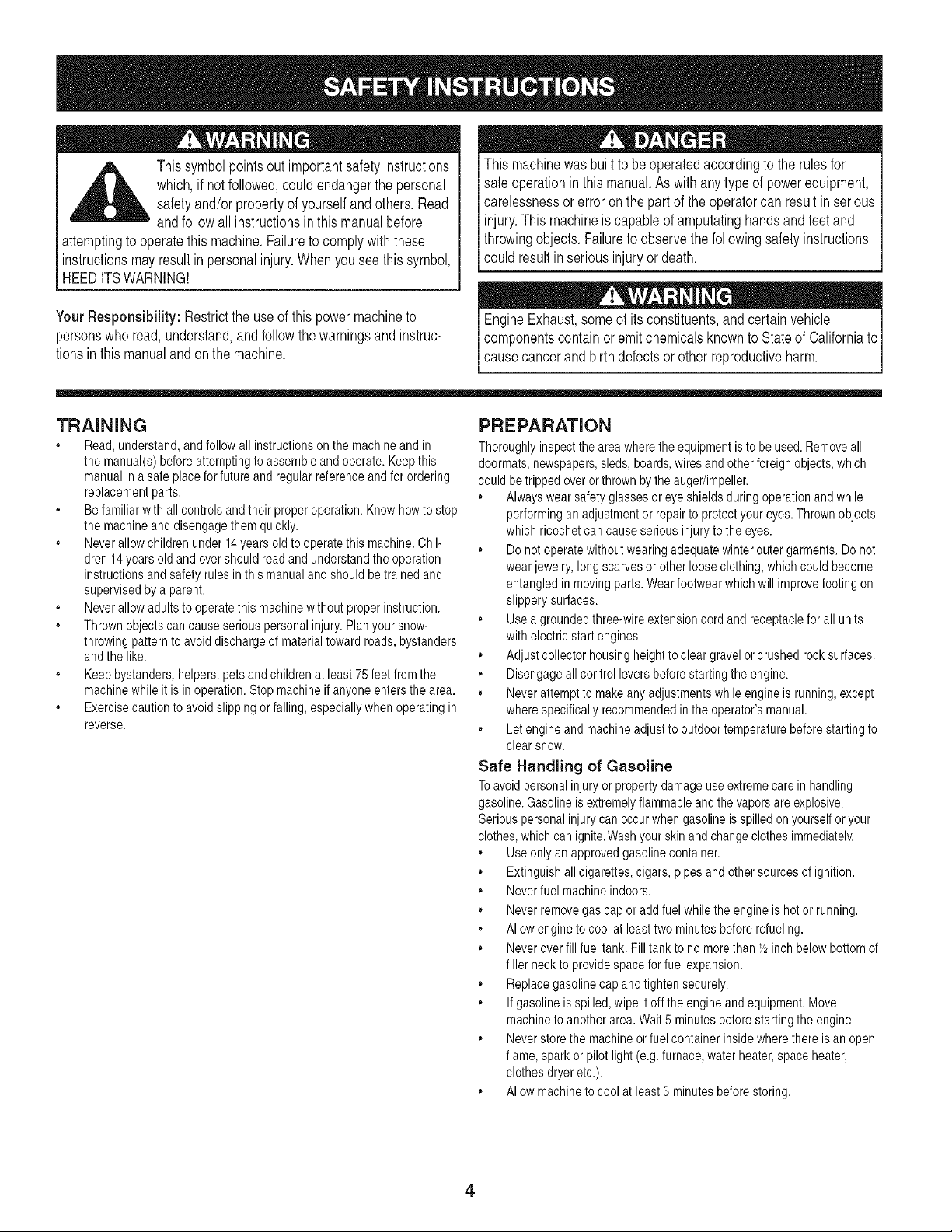
__L Thissymbolpointsoutimportantsafetyinstructions
which,ifnotfollowed,couldendangerthepersonal
safetyand/orpropertyofyourselfandothers.Read
andfollowallinstructionsinthismanualbefore
attemptingtooperatethismachine.Failuretocomplywiththese
instructionsmayresultinpersonalinjury.Whenyouseethissymbol,
HEEDITSWARNING!
YourResponsibility:Restricttheuseofthispowermachineto
personswhoread,understand,andfollowthewarningsandinstruc-
tionsinthismanualandonthemachine.
Thismachinewasbuilttobeoperatedaccordingtotherulesfor
safeoperationinthismanual.Aswithanytypeofpowerequipment,
carelessnessorerroronthepartoftheoperatorcanresultinserious
injury.Thismachineiscapableofamputatinghandsandfeetand
throwingobjects.Failuretoobservethefollowingsafetyinstructions
couldresultinseriousinjuryordeath.
Engine Exhaust, some of its constituents, and certain vehicle
components contain or emit chemicals known to State of California to
1cause cancer and birth defects or other reproductive harm.
TRAINING
,, Read,understand,andfollowall instructionson the machineand in
the manual(s)beforeattemptingto assembleand operate.Keepthis
manualina safe placefor future andregularreferenceandfor ordering
replacementparts.
,, Be familiarwith all controls andtheir properoperation.Knowhowto stop
the machineanddisengagethem quickly.
,, Neverallowchildrenunder 14years oldto operatethis machine.Chil-
dren 14years old and overshouldread and understandthe operation
instructionsand safetyrulesin this manualand shouldbe trained and
supervisedbya parent.
,, Neverallowadultsto operatethis machinewithout properinstruction.
,, Thrownobjectscan causeseriouspersonalinjury.Planyour snow-
throwingpatternto avoid dischargeof materialtoward roads,bystanders
andthe like.
,, Keepbystanders,helpers,petsandchildren at least 75 feet fromthe
machinewhileit is inoperation.Stop machineif anyoneentersthe area.
,, Exercisecaution to avoid slippingorfalling, especiallywhenoperatingin
reverse.
PREPARATION
Thoroughlyinspecttheareawheretheequipmentis to be used.Removeall
doormats,newspapers,sleds,boards,wiresandotherforeignobjects,which
couldbe trippedoverorthrownbythe auger/impeller.
,, Alwayswearsafetyglasses or eye shields duringoperationandwhile
performinganadjustmentor repairto protectyour eyes. Thrownobjects
which ricochetcan causeserious injuryto the eyes.
,, Donot operatewithoutwearing adequatewinterouter garments.Donot
wearjewelry, longscarvesor otherlooseclothing,whichcouldbecome
entangledinmoving parts.Wearfootwearwhichwill improvefootingon
slippery surfaces.
,, Usea groundedthree-wireextensioncord and receptaclefor all units
with electricstart engines.
,, Adjust collector housingheightto clear gravelor crushedrocksurfaces.
,, Disengageall controlleversbeforestartingthe engine.
,, Neverattemptto makeany adjustmentswhileengineis running,except
where specificallyrecommendedinthe operator'smanual.
,, Letengineand machineadjustto outdoortemperaturebeforestartingto
clear snow.
Safe Handling of Gasoline
Toavoidpersonalinjuryor propertydamageuse extremecarein handling
gasoline.Gasolineis extremelyflammableand the vaporsare explosive.
Seriouspersonalinjury can occurwhen gasolineis spilledonyourselfor your
clothes,whichcan ignite.Washyour skinand changeclothesimmediately.
,, Useonly an approvedgasolinecontainer.
,, Extinguishall cigarettes,cigars,pipesand othersourcesof ignition.
,, Neverfuel machineindoors.
,, Neverremovegas cap or addfuel whilethe engine is hot or running.
,, Allow engine to cool at least two minutesbefore refueling.
,, Neveroverfill fuel tank.Fill tank to no morethan Y2inch belowbottomof
filler neck to providespacefor fuel expansion.
,, Replacegasolinecap andtighten securely.
,, If gasolineis spilled, wipeit off the engineandequipment.Move
machineto anotherarea.Wait5 minutesbeforestartingthe engine.
,, Neverstore the machineor fuel container insidewherethere is an open
flame, sparkor pilot light (e.g.furnace,water heater,space heater,
clothesdryeretc.).
,, Allow machineto cool at least 5 minutes beforestoring.
4
OPERATION
. Do notputhands orfeet near rotatingparts, in the auger/impeller
housingor chuteassembly.Contactwith the rotatingparts can amputate
handsand feet.
,, The auger/impellercontrol leveris a safetydevice.Neverbypassits
operation.Doingso makesthe machineunsafeand maycause personal
injury.
,, The control leversmust operateeasilyin both directionsand automati-
cally returnto the disengagedpositionwhenreleased.
,, Neveroperatewitha missingor damagedchute assembly.Keepall
safetydevices inplaceand working.
,, Neverrunan engineindoorsor in a poorlyventilatedarea.Engine
exhaustcontainscarbonmonoxide,anodorlessanddeadlygas.
,, Do notoperatemachinewhileunderthe influenceof alcoholor drugs.
,, Mufflerand enginebecomehot and can causea burn. Do nottouch.
. Exerciseextremecautionwhenoperatingon or crossinggravel surfaces.
Stay alertfor hidden hazardsortraffic.
. Exercisecaution whenchangingdirectionand while operatingon slopes.
. Plan yoursnow-throwingpatternto avoid dischargetowardswindows,
walls, carsetc. Thus, avoidingpossiblepropertydamage or personal
injurycaused bya ricochet.
. Neverdirectdischargeat children,bystandersand petsor allow anyone
infront of the machine.
. Do notoverloadmachinecapacityby attemptingto clearsnow at too fast
of a rate.
. Neveroperatethis machinewithoutgood visibilityor light. Alwaysbe
sureof your footing andkeepa firm hold on the handles.Walk, never
run.
. Disengagepowerto the auger/impellerwhentransportingor notin use.
,, Neveroperatemachineat hightransportspeedson slipperysurfaces.
Lookdown and behindand use carewhen backingup.
,, If the machineshouldstart to vibrate abnormally,stop the engine,
disconnectthe sparkplug wire andgroundit againstthe engine.Inspect
thoroughlyfor damage.Repairany damagebeforestartingand operat-
ing.
. Disengageallcontrolleversandstop enginebeforeyou leave the
operatingposition(behindthe handles).Wait until the auger/impeller
comesto a completestop beforeuncloggingthe chute assembly,making
any adjustments,orinspections.
,, Neverputyour handin the dischargeor collectoropenings.Always
use the clean-outtool providedto unclogthe dischargeopening. Do
not unclogchute assemblywhileengineis running.Shut off engine
and remainbehindhandlesuntil all movingparts havestoppedbefore
unclogging.
,, Use only attachmentsand accessoriesapprovedbythe manufacturer
(e.g. wheelweights,tire chains,cabsetc.).
,, If situationsoccurwhich are not coveredinthis manual,use careand
goodjudgment. Contactyour Sears ServiceCenter forassistance.
MAINTENANCE & STORAGE
. Nevertamperwith safetydevices.Checktheir properoperation
regularly.Referto the maintenanceandadjustmentsectionsof this
manual.
,, Beforecleaning, repairing,or inspectingmachinedisengageall control
leversand stop the engine.Wait until the auger/impellercome to a
completestop.Disconnectthe sparkplug wireand groundagainstthe
engine to preventunintendedstarting.
. Check bolts andscrewsfor propertightnessat frequentintervalsto keep
the machinein safe workingcondition.Also, visually inspectmachinefor
any damage.
. Donotchangethe enginegovernorsettingor over-speedthe engine.
The governorcontrolsthe maximumsafe operatingspeedof the engine.
. Snow throwershaveplatesandskid shoesare subjectto wearand
damage.Foryour safetyprotection,frequentlycheck all components
and replacewith originalequipmentmanufacturer's(OEM) partsonly.
"Useof partswhich do not meetthe originalequipmentspecifications
may leadto improperperformanceandcompromisesafety!"
. Checkcontrols periodicallyto verify theyengageand disengage
properly andadjust,if necessary.Referto the adjustmentsectionin this
operator'smanualfor instructions.
. Maintainor replacesafetyand instructionlabels,as necessary.
. Observeproperdisposallawsand regulationsfor gas, oil,etc. to protect
the environment.
. Priorto storing,run machinea few minutesto clearsnowfrom machine
and preventfreezeup of auger/impeller.
. Neverstorethe machineor fuel container insidewherethere is an open
flame, sparkor pilot lightsuch asa water heater,furnace,clothes dryer
etc.
,, Alwaysreferto the operator'smanualfor properinstructionson
off-seasonstorage.
Do not modify engine
Toavoidseriousinjuryor death,do notmodifyenginein anyway.Tampering
withthe governorsettingcan leadto a runawayengine andcauseit to operate
at unsafespeeds.Nevertamperwithfactorysettingof engine governor.
Notice Regarding Emissions
Engineswhichare certifiedto complywith CaliforniaandfederalEPAemission
regulationsfor SORE(SmallOff RoadEquipment)are certifiedto operateon
regularunleadedgasoline,and may includethefollowingemissioncontrol sys-
tems:EngineModification(EM)andThreeWayCatalyst(TWO)if so equipped.

This page left intentionallyblank.
6
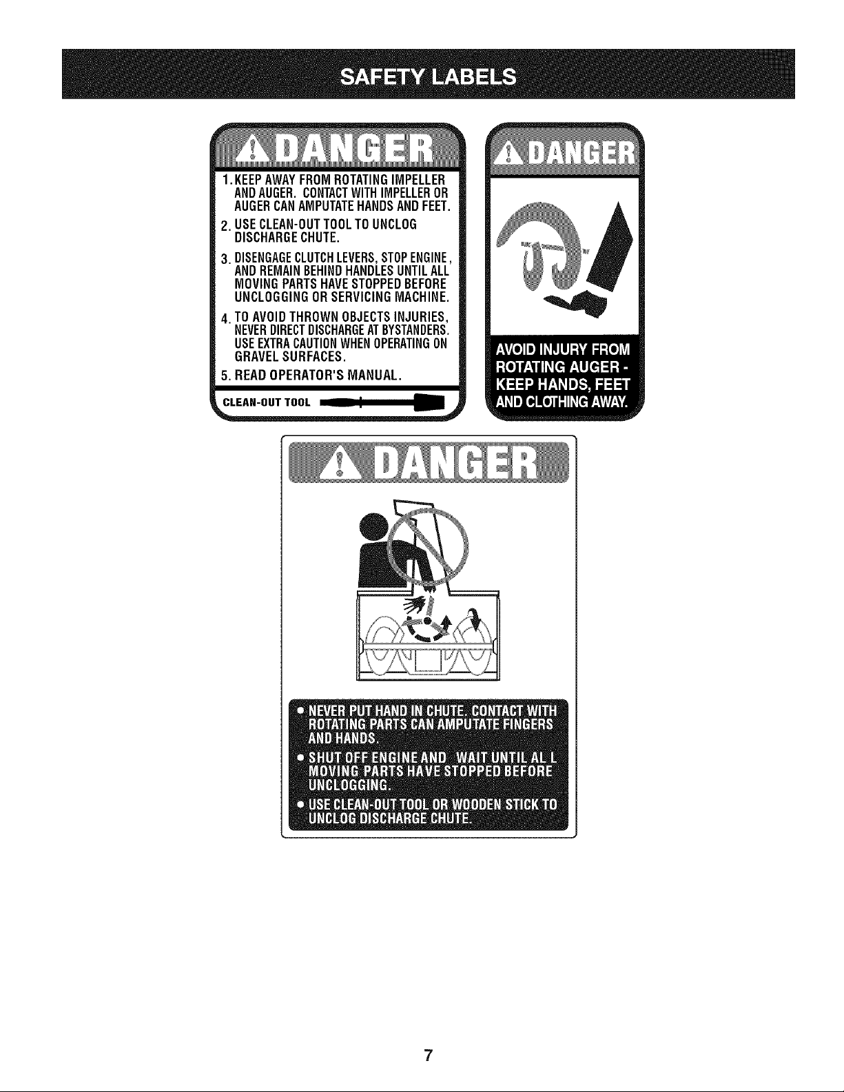
1. KEEPAWAYFROMROTATINGIMPELLER
ANDAUGER.CONTACTWITHIMPELLEROR
AUGERCANAMPUTATEHANDSANDFEET.
2. USECLEAN-OUTTOOLTOUNCLOG
DISCHARGECHUTE.
3. DISENGAGECLUTCHLEVERS,STOPENGINE,
ANDREMAINBEHINDHANDLESUNTILALL
MOVINGPARTSHAVESTOPPEDBEFORE
UNCLOGGINGORSERVICINGMACHINE.
4. TOAVOIDTHROWNOBJECTSINJURIES,
NEVERDIRECTDISCHARGEATBYSTANDERS.
USEEXTRACAUTIONWHENOPERATINGON
GRAVELSURFACES.
5. READOPERATOR'SMANUAL.
CL_K-O_T_LU___
7
NOTE:Referencesto rightor left sideof the snowthrowerare
determinedfrombehindthe unit inthe operatingposition(standing
directlybehindthesnow thrower,facingthe handlepanel).
REMOVING FROM CARTON
1. Cutthe cornersof thecarton and lay the sidesflat onthe ground.
Removeand discardall packinginserts.
2. Movethe snowthrowerout of thecarton.
3. Makecertainthe carton hasbeencompletelyemptiedbefore
discardingit.
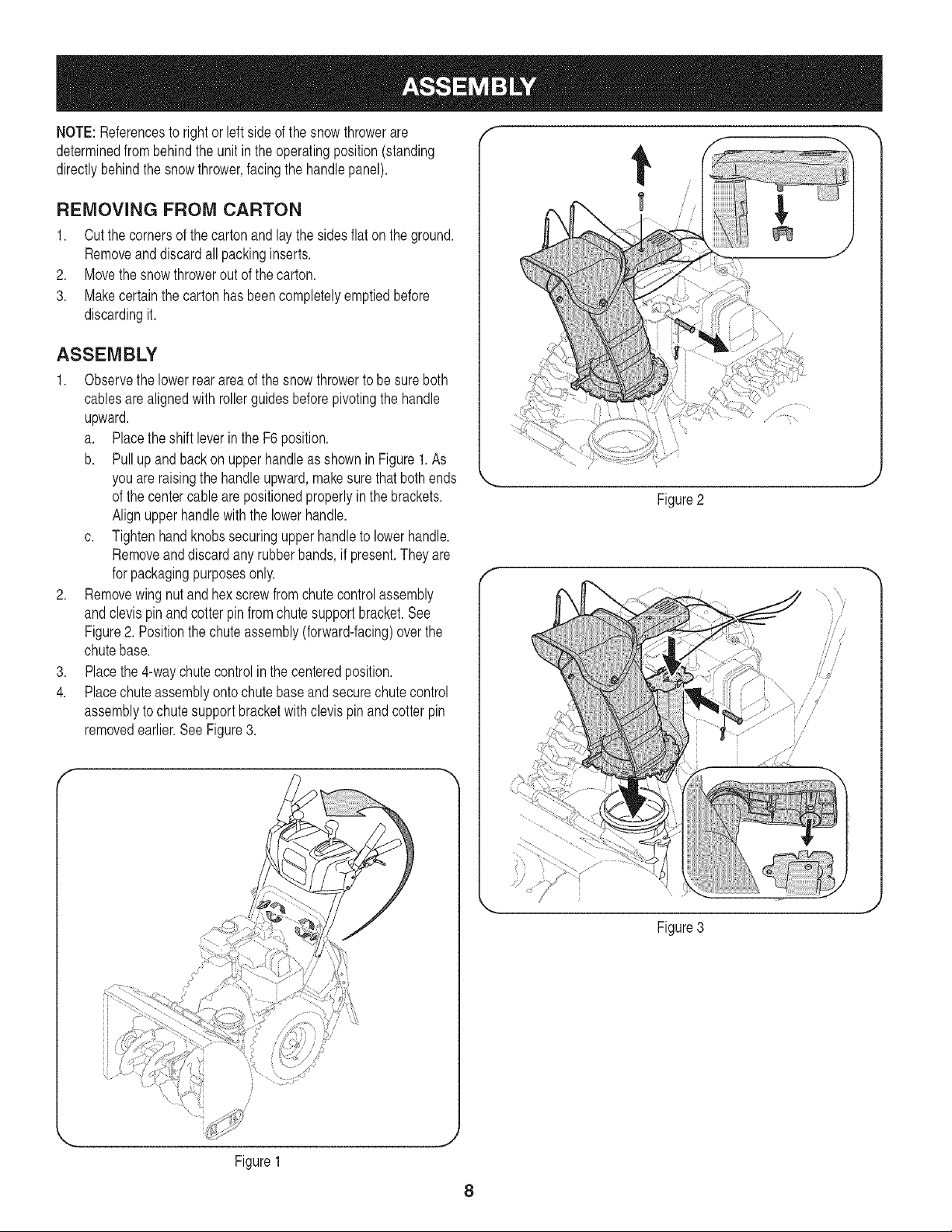
ASSEMBLY
1. Observethe lowerrear area of the snowthrowerto besureboth
cablesarealignedwith rollerguidesbeforepivotingthe handle
upward.
a. Placetheshift leverin the F6position.
b. Pullupand backon upperhandleas showninFigure1.As
youare raisingthe handleupward,makesurethat bothends
of the centercablearepositionedproperlyin the brackets.
Alignupperhandlewiththe lowerhandle.
c. Tightenhandknobssecuringupperhandleto lowerhandle.
Removeanddiscard anyrubberbands, if present.Theyare
for packagingpurposesonly.
2. Removewingnut andhexscrewfrom chutecontrolassembly
andclevispin and cotter pin fromchute supportbracket.See
Figure2. Positionthe chuteassembly(forward-facing)overthe
chutebase.
3. Placethe 4-waychutecontrol in the centeredposition.
4. Placechuteassemblyontochutebaseand secure chutecontrol
assemblyto chute supportbracketwithclevis pin and cotterpin
removedearlier.See Figure3.
f
Figure1
Figure2
J ,
\ //
Figure3
8
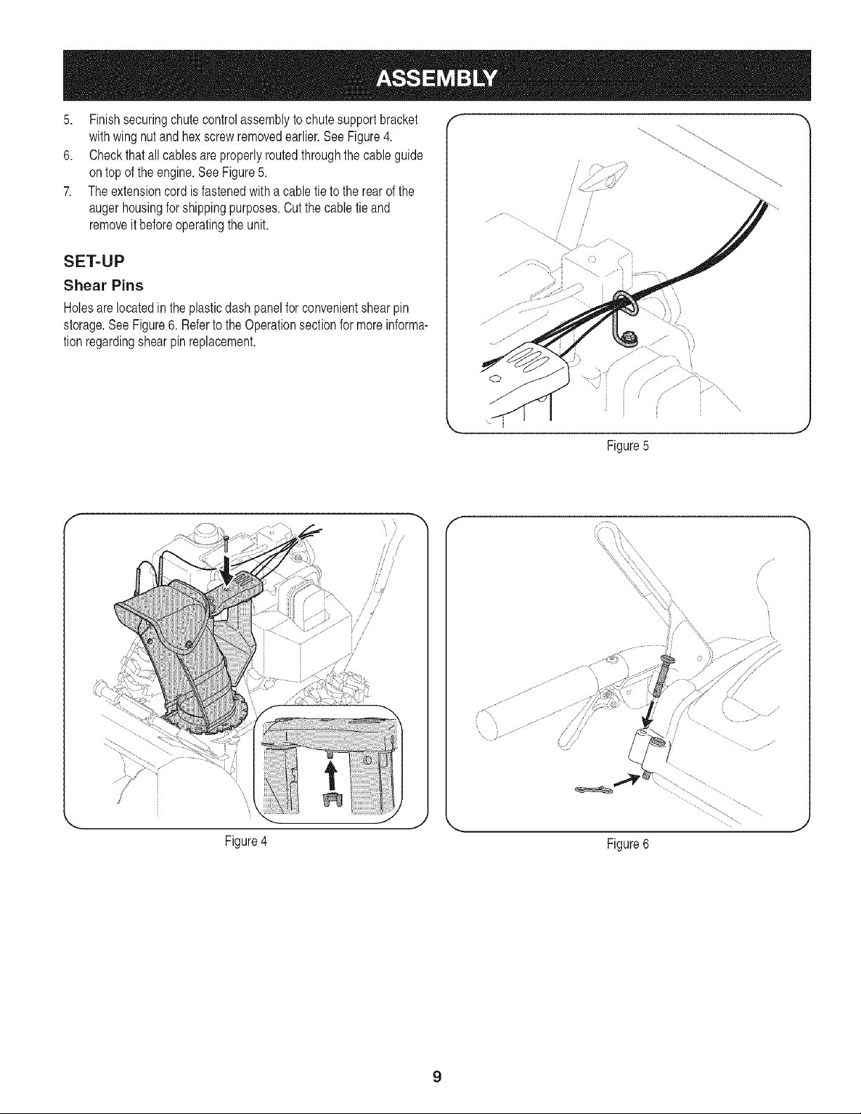
5. Finishsecuringchutecontrolassemblyto chutesupportbracket
withwing nutand hex screwremovedearlier.See Figure4.
6. Checkthat all cables are properlyroutedthroughthe cableguide
ontop of the engine.See Figure5.
7. The extensioncord is fastenedwith a cabletie to the rear of the
augerhousingforshippingpurposes.Cutthe cabletie and
removeit beforeoperatingthe unit.
SET=UP
Shear Pins
Holesare locatedinthe plasticdashpanel forconvenientshearpin
storage.See Figure6. Referto the Operationsectionfor moreinforma-
tion regardingshearpin replacement.
Figure5
Figure4
//
//
J //
jJ
/ / j/
Figure6
9
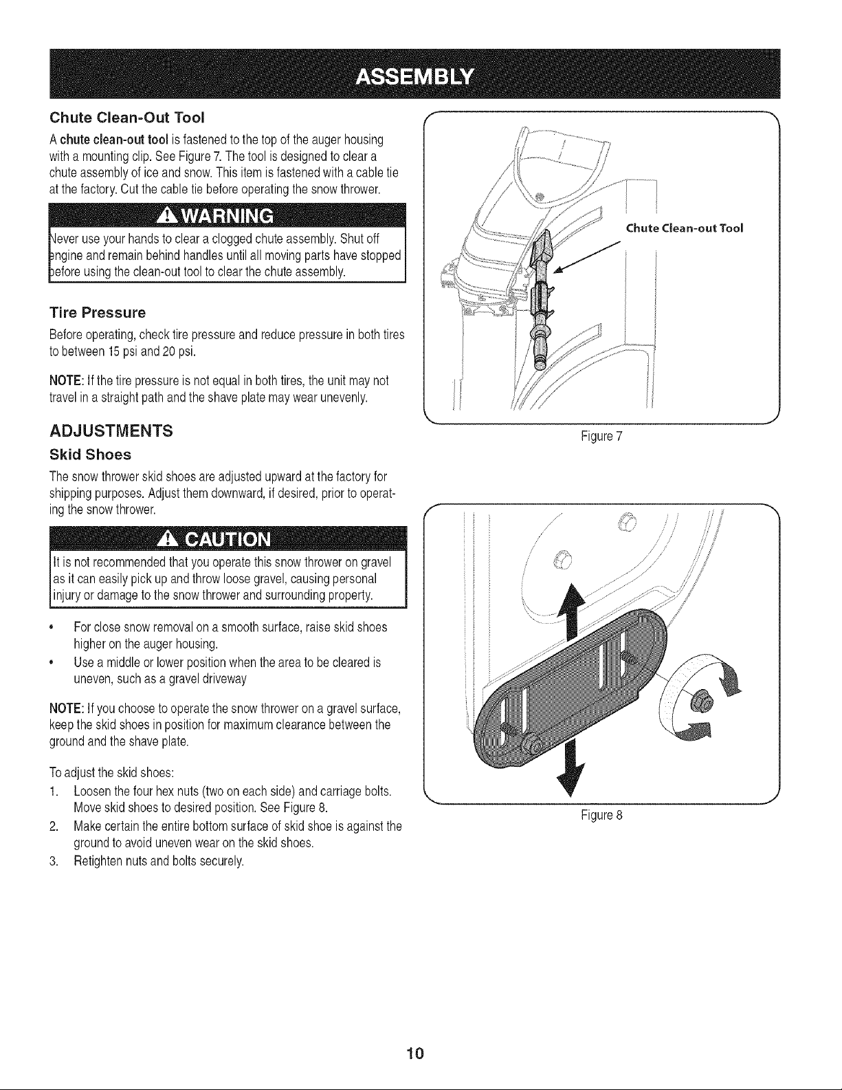
Chute Clean=Out Tool
Achute clean-out tool is fastenedto the topof theauger housing
witha mountingclip. See Figure7.The tool is designedto cleara
chuteassemblyof iceand snow.This itemis fastenedwithacable tie
atthe factory.Cut thecable tie beforeoperatingthe snowthrower.
_leveruse yourhandsto cleara cloggedchuteassembly.Shutoff I
I
_ngineandremainbehindhandlesuntilall movingparts havestoppedI
I
_eforeusingthe clean-outtool to clearthe chuteassembly. J
Tire Pressure
Beforeoperating,checktire pressureand reducepressurein bothtires
tobetween 15psi and 20 psi.
NOTE:If the tire pressureis notequal in bothtires,the unit maynot
travelina straightpathand the shaveplatemaywearunevenly.
ADJUSTMENTS
Skid Shoes
The snow throwerskid shoesare adjustedupwardat the factoryfor
shippingpurposes.Adjustthemdownward,if desired,priorto operat-
ingthe snowthrower.
It is notrecommendedthat youoperatethissnowthrowerongravel
as it can easilypickup andthrowloosegravel,causingpersonal
injuryor damageto thesnowthrowerandsurroundingproperty.
• Forclose snowremovalon a smoothsurface,raiseskid shoes
higheronthe auger housing.
• Usea middleor lowerpositionwhenthe areato be clearedis
uneven,suchas a graveldriveway
NOTE:If you chooseto operatethe snowthroweron a gravelsurface,
keepthe skidshoesin positionfor maximumclearancebetweenthe
groundand theshave plate.
Toadjust the skid shoes:
1. Loosenthe fourhex nuts (two on eachside) andcarriagebolts.
Moveskidshoesto desiredposition.SeeFigure8.
2. Makecertainthe entirebottomsurfaceof skid shoe is againstthe
groundto avoidunevenwearon the skid shoes.
3. Retightennuts and bolts securely.
Chute Clean-out Tool
Figure7
/
/ /
/
Figure8
10
Auger Control
Priorto operatingyoursnowthrower,carefullyread and followall
instructionsbelow.Performall adjustmentstoverify yoursnow
throweris operatingsafelyand properly.
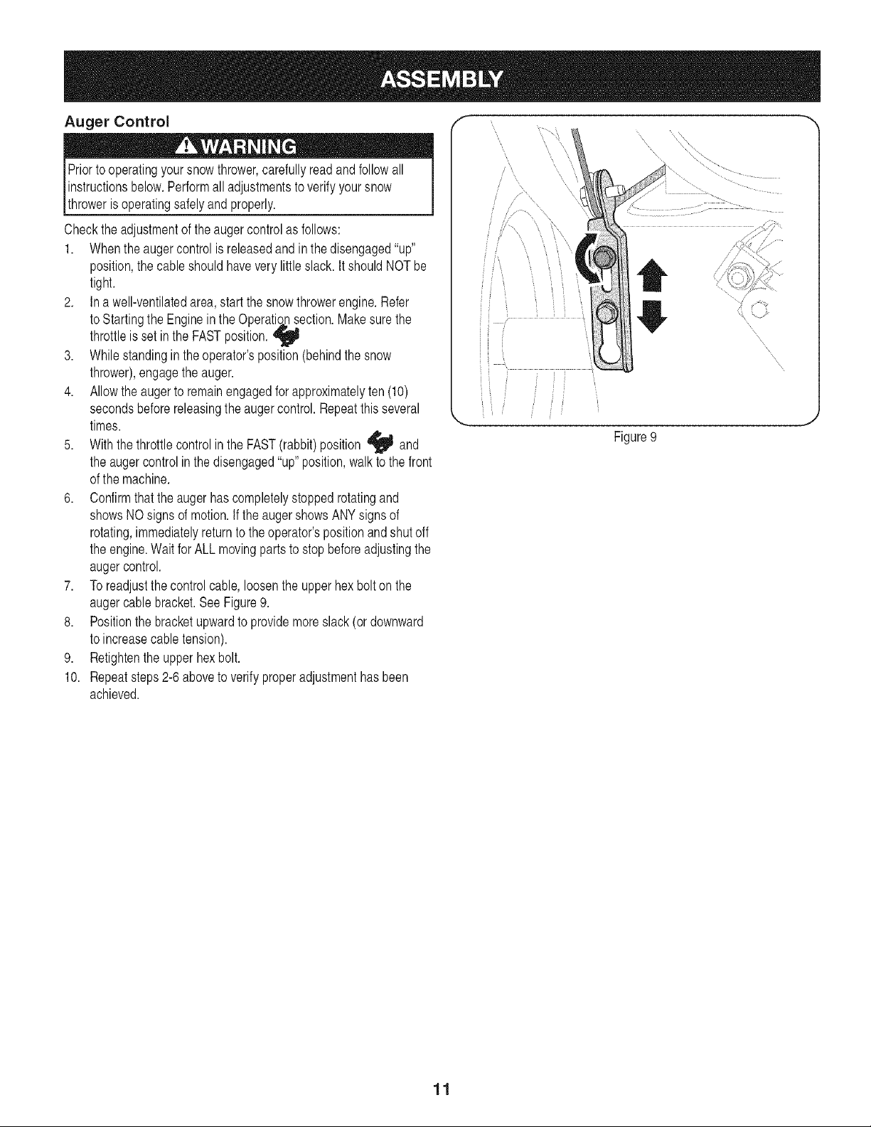
Checktheadjustmentof the augercontrolasfollows:
1. Whenthe augercontrolis releasedandin the disengaged"up"
position,the cableshouldhavevery little slack. It shouldNOT be
tight.
2. In a well-ventilatedarea,start the snowthrowerengine.Refer
to Startingthe Engineinthe Operatlohnsection.Makesurethe
throttleis set in the FASTposition.
3. Whilestandingin the operator'sposition(behindthe snow
thrower),engagethe auger.
4. Allowthe augerto remainengagedfor approximatelyten (10)
secondsbeforereleasingthe augercontrol.Repeatthisseveral
times.
5. Withthethrottlecontrol in the FAST(rabbit)position _ and
the augercontrolin the disengaged"up"position,walkto the front
of the machine.
6. Confirmthat the augerhascompletelystoppedrotatingand
showsNO signsof motion.If the augershowsANYsignsof
rotating,immediatelyreturnto the operator'spositionand shut off
the engine.Waitfor ALL movingparts to stopbeforeadjustingthe
augercontrol.
7. Toreadjustthe control cable,loosenthe upperhexbolt onthe
augercable bracket.See Figure9.
8. Positionthe bracketupwardto providemoreslack(or downward
to increasecable tension).
9. Retightenthe upperhexbolt.
10. Repeatsteps2-6aboveto verifyproperadjustmenthasbeen
achieved.
......., ......
\
Figure9
11
Drive
Chute
Aseerably
Headli,
ElectricStart Bntte_
GasCap
Oil Fill
Cleen-DntTool
Augers
ShiftLever
Four-Way
ChuteControFM
-,_:-------Auger Control
WheelSteeringControl
Y
EngineContreJs
Recoil Starter
ttandle
Electric Starter Outlet
Primer
Choke
Control
%, J
_,, ,._
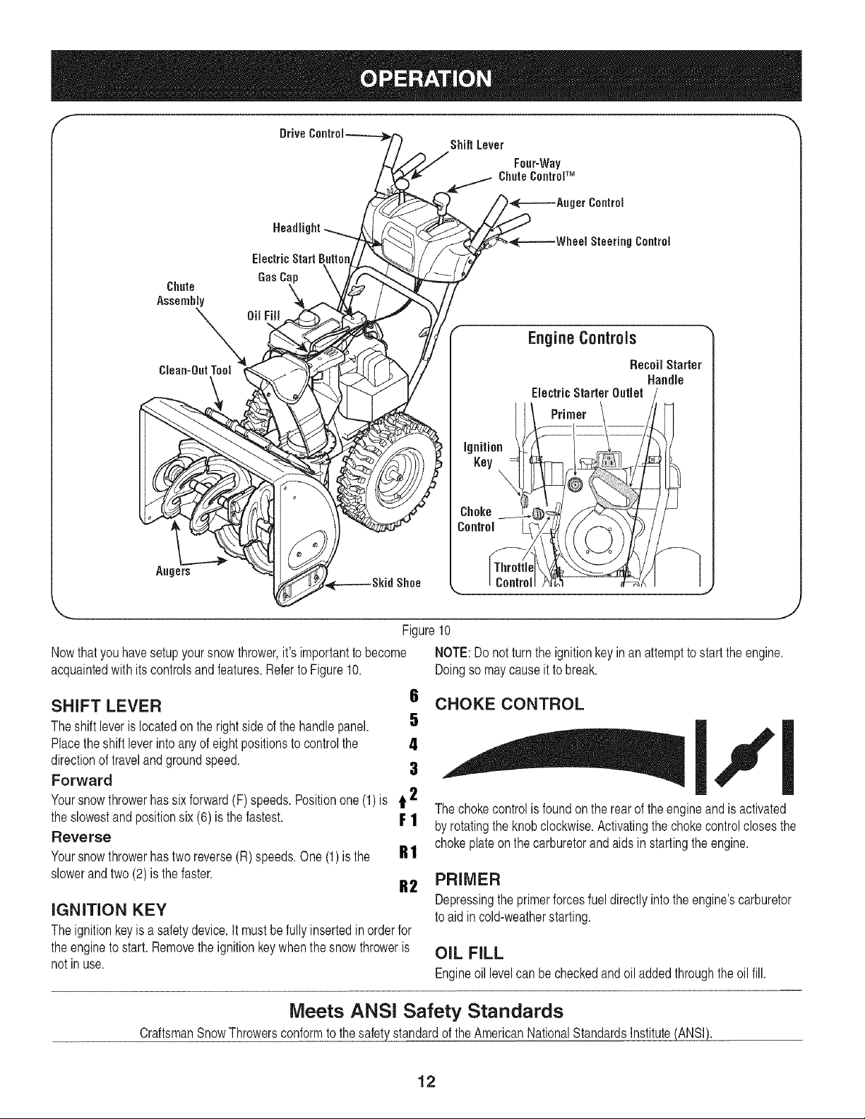
Figure10
Nowthatyouhavesetupyoursnow thrower,it's importantto become NOTE:Do not turnthe ignitionkey in an attemptto startthe engine.
acquaintedwith itscontrolsand features.Referto Figure10. Doingso maycauseit to break.
SHIFT LEVER
Theshift leveris locatedon the rightsideof the handle panel.
Placetheshift leverinto anyof eightpositionsto controlthe
directionof travelandgroundspeed.
Forward
Yoursnowthrowerhassix forward(F) speeds.Positionone (1)is t 2
the slowestand positionsix (6) is the fastest. F 1
Reverse
Yoursnowthrowerhastwo reverse(R)speeds.One (1) is the g t
slowerandtwo(2) is the faster.
R2
IGNITION KEY
Theignitionkey is a safetydevice.It mustbe fully insertedin orderfor
the engineto start.Removethe ignitionkeywhenthesnow throweris
not in use.
6 CHOKE CONTROL
5
The chokecontrolis foundon the rearof theengine and is activated
byrotatingthe knobclockwise.Activatingthechokecontrolclosesthe
chokeplateon the carburetorand aids instartingthe engine.
PRIMER
Depressingthe primerforcesfueldirectlyinto theengine'scarburetor
to aid in cold-weatherstarting.
OIL FILL
Engineoil levelcan be checkedandoil addedthroughtheoil fill.
Meets ANSI Safety Standards
CraftsmanSnowThrowersconformto thesafety standardof the AmericanNationalStandardsInstitute(ANSI).
12
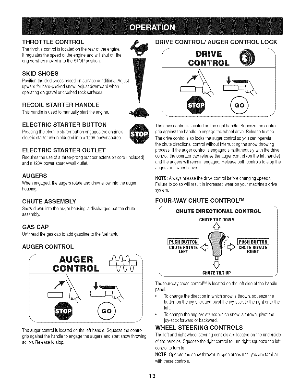
THROTTLE CONTROL
The throttlecontrolis locatedon the rearof theengine.
It regulatesthe speedof the engineand willshut off the
enginewhenmovedintothe STOPposition.
SKID SHOES
Positionthe skid shoes basedon surfaceconditions.Adjust
upwardfor hard-packedsnow.Adjustdownwardwhen
operatingon gravelor crushedrock surfaces.
RECOIL STARTER HANDLE
This handleis usedto manuallystart theengine.
J
DRIVE CONTROL/AUGER CONTROL LOCK
S
DRIVE
CONTROL
@
ELECTRIC STARTER BUTTON
Pressingthe electricstarterbuttonengagesthe engine's
electricstarterwhen pluggedintoa 120Vpowersource.
ELECTRIC STARTER OUTLET
Requiresthe use ofa three-prongoutdoorextensioncord (included)
anda 120Vpowersource/walloutlet.
AUGERS
When engaged,the augersrotateand drawsnowintothe auger
housing.
The drivecontrolis locatedon the righthandle.Squeezethe control
gripagainstthe handleto engagethe wheeldrive.Releaseto stop.
The drivecontrolalso locksthe augercontrolso you canoperate
the chute directionalcontrolwithoutinterruptingthe snowthrowing
process.If the augercontrolis engagedsimultaneouslywith the drive
control,the operatorcanreleasetheauger control(on the left handle)
andthe augerswill remainengaged.Releaseboth controlsto stop the
augersand wheeldrive.
NOTE:Alwaysreleasethedrive controlbeforechangingspeeds.
Failureto doso will result in increasedwearon yourmachine'sdrive
system.
CHUTE ASSEMBLY
Snowdrawnintothe augerhousingis dischargedout the chute
assembly.
GAS CAP
Unthreadthe gascap to add gasolineto thefuel tank.
AUGER CONTROL
S
The auger controlis locatedonthe lefthandle.Squeezethe control
gripagainstthe handleto engagethe augersandstart snowthrowing
action.Releaseto stop.
FOUR=WAY CHUTE CONTROL TM
f
CHUTE DIRECTIONAL CONTROL
[PHSHH°TTO.I©CHUTEROTATE
LEFT
JPUSH BUTTON J
CHUTEROTATE
HIGHT
©
_. CHUTETiLTUP j
The four-waychutecontrolTM is locatedon the leftsideof the handle
panel.
,, Tochangethe directionin which snowis thrown,squeezethe
buttononthe joy-stickand pivotthejoy-stickto the rightor to the
left.
,, Tochangethe angle/distancewhich snow is thrown,pivot the
joy-stickforwardor backward.
WHEEL STEERING CONTROLS
The left and rightwheelsteeringcontrolsare locatedonthe underside
of the handles.Squeezethe rightcontrolto turn right; squeezethe left
controlto turnleft.
NOTE:Operatethe snow throwerin open areasuntilyouarefamiliar
withthesecontrols.
13
CLEAN-OUT TOOL
fever useyour handsto clear acloggedchuteassembly.Shutoff I
gineandremainbehind handlesuntilall movingparts havestoppedI
fore usingthe clean-outtool toclear the chuteassembly, j
Thechute clean-outtoolis convenientlyfastenedto the rearof the
augerhousingwith a mountingclip. Shouldsnowand ice become
lodgedin the chuteassemblyduring operation,proceedas followsto
safelycleanthechute assemblyand chute opening:
1. ReleaseboththeAuger Controland the DriveControl.
2. Stopthe engineby removingthe ignitionkey.
3. Removethe clean-outtool fromthe clip which securesit to the
rearof the augerhousing.
4. Usetheshovel-shapedendof the clean-outtool to dislodgeand
scoopany snowand ice whichhasformedin andnearthechute
assembly.
5. Refastenthe clean-outtool to the mountingclip on the rearof
theauger housing,reinsertthe ignitionkeyandstartthe snow
thrower'sengine.
6. Whilestandingin the operator'sposition(behindthe snow
thrower),engagethe augercontrolfora fewsecondsto clearany
remainingsnow and ice fromthechuteassembly.
BEFORE STARTING ENGINE
Read,understand,and followall instructionsandwarningsonthe
machineand inthis manualbeforeoperating.
Oil
Theunit was shippedwithoil inthe engine.Checkoil levelbeforeeach
operationto ensureadequateoil inthe engine.Forfurtherinstructions,
referto the stepsonpage 16.
1. Removethe dipstickfromthe oil fill.
2. Checkand makesurethat the levelof oil is up to theFULL mark
onthe dipstick.
3. If theoil levelis notup to FULL,pourfresh motoroil (5W-30,with
a minimumclassificationof SL/SJ)slowlythroughthe opening.
Replaceoil fill dipstickand checkoil levelagain.
Gasoline
Useextremecarewhenhandlinggasoline.Gasolineis extremely
flammableand the vaporsareexplosive.Neverfuel the machine
indoorsor whilethe engineis hot or running.Extinguishcigarettes,
[c gars, p pesand othersourcesof gnt on.
,, Storegasolinein aclean,approvedcontainerand keepthe cap in
placeon the container.
,, Makesurethat the containerfrom which you pourthe gasolineis
cleanand freefrom rust or otherforeignparticles.
NOTE:A plasticdust cap maybefound insidethe fuel fill opening.
Removeand discard,if present.
,, Alwaysfill thefuel tankoutdoorsand usea funnelorspoutto
preventspilling.
,, Fillfuel tank with clean,fresh,unleadedgasoline.
,, Neverfill thefuel tank completely.Fillthe tank to within1/2" from
the top to providespaceforexpansionof fuel.
,, Makesureto wipeoff anyspilledfuel beforestartingthe engine.
STARTING THE ENGINE
1. Attachspark plugwire to sparkplug.Makecertainthe metal
loopon theend of the sparkplugwire(insidethe rubberboot) is
fastenedsecurelyoverthe metaltip on the spark plug.
2. Makecertainboththe augercontrolanddrivecontrolare in the
disengaged(released)position.
3. Movethrottlecontrol up to FAST_ position.Insertignitionkey
intoslot. Makesureit snapsinto place.Donot attemptto turn the
key.
NOTE:The enginecannotstart withoutthe keyis fullyinsertedintothe
ignitionswitch.
Electric Starter
Determinethat yourhome'swiringis a three-wiregroundedsystem.
Aska licensedelectricianif you are not certain.
The optionalelectricstarteris equippedwith a groundedthree-wire
powercordand plug,and is designedto operateon 120voltAC
householdcurrent.It mustbe usedwith aproperlygroundedthree-
prongreceptacleat all timesto avoidthepossibilityof electricshock.
Followall instructionscarefullypriorto operatingthe electricstarter.
Ifyou havea groundedthree-prongreceptacle,proceedas follows:
1. Plugthe extensioncord intothe outlet locatedon the engine's
surface.Plugtheotherend of extensioncordinto a three-prong
120-volt,grounded,ACoutlet in a well-ventilatedarea.
2. Rotatechokecontrolto FULL IJl chokeposition(for a cold
enginestart).
NOTE:If theengine is alreadywarm,placechokecontrolin the OFF
positioninsteadof FULL IJl •
3. Pushtheprimertwo or threetimesfor coldenginestart, making
sureto covervent hole in the centerof the primerwhenpushing.
NOTE:DO NOTuse primerto restarta warmengineaftera short
shutdown.
4. Pushstarterbuttonto start engine.
NOTE:Do not hold the buttondownfor longerthanseven (7) seconds
at a time. Doingso maydamageyourengine'selectricstarter.
14
5. Oncethe enginestarts,releasestarterbutton.
6. As the enginewarms,slowlyrotatechokecontrolto theOFF
position.If the enginefalters,quicklyrotatechokecontrolbackto
FULL I,,_1 thenslowlyintothe OFFpositionagain.
7. Whendisconnectingthe extensioncord, alwaysunplugthe end
at the three-prongwall outletbeforeunpluggingthe oppositeend
fromthe snowthrower.
Recoil Starter
1. Rotatechoke controlto FULL IJl chokeposition(coldengine
start).
NOTE: If the engineis alreadywarm, placechokecontrolinthe OFF
insteadof FULL IJ|.
position
2. Pushthe primertwo or threetimes forcold enginestart, making
sureto covervent hole in the centerof the primerwhenpushing.
NOTE: DONOT useprimerto restartawarmengineaftera short
shutdown.
NOTE:Additionalprimingmaybe necessaryif the temperatureis
below15° Fahrenheit.
3. Graspthe recoilstarterhandleandslowlypullthe rope out. At the
pointwhereit becomesslightlyharderto pullthe rope,slowly
allowthe rope to recoil.
4. Pullthe starterhandlewith a firm,rapid stroke.Do notrelease
the handleand allowit to snapback.Keepa firm hold on the
starterhandleand allow it to slowlyrecoil.
5. As the enginewarms,slowlyrotatethe chokecontrolto the OFF
position.If the enginefalters,quicklyrotatethe chokecontrol
backto the FULL I,,_1 positionandthenslowlyinto the OFF
positionagain.
NOTE:Allowthe engineto warmupfor a few minutesafterstarting.
The enginewill notdevelopfull poweruntilit reachesoperating
temperatures.
STOPPING THE ENGINE
Runenginefor a few minutesbeforestoppingto helpdry off any
moistureon the engine.
Movethrottlecontrolto STOP
1.
position.
2. Removethe ignitionkeyandstoreina safeplace.
3. Wipeall snowand moisturefromthe areaaroundthe engineas
wellas the areainand aroundthe drivecontrol and augercontrol.
Also,engageandreleasebothcontrolsseveraltimes.
TO ENGAGE DRIVE
1. Withthethrottlecontrol in the Fast_ position,moveshift lever
intoone of the six forward(F) positionsor tworeverse(R)
positions.Selecta speedappropriatefor the snowconditionsand
a paceyou'recomfortablewith.
NOTE: Whenselectinga DriveSpeed,usethe slowerspeedsuntil
you are comfortableand familiarwith theoperationof the snow
thrower.
2. Squeezethe drivecontrolagainstthe handleandthe snow
throwerwill move.Releaseit anddrive motionwillstop.
NOTE:NEVERrepositionthe shift lever(changespeedsor direction
of travel)withoutfirst releasingthedrive controlandbringingthesnow
throwerto a completestop.Doingso will resultin prematurewearto
the snowthrower'sdrivesystem.
TO ENGAGE AUGERS
1. Toengagethe augersand startthrowingsnow,squeezethe
augercontrolagainstthe left handle.Releaseto stopthe augers.
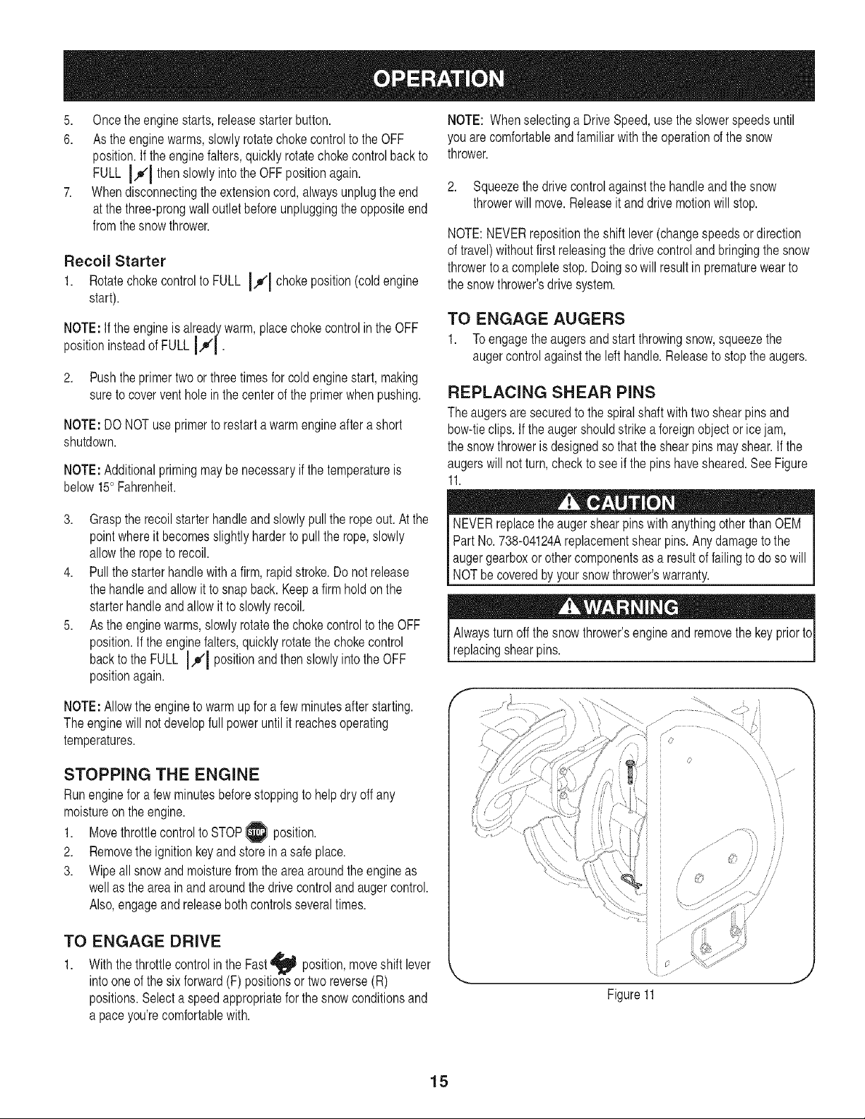
REPLACING SHEAR PINS
The augersaresecuredto the spiralshaft with two shearpinsand
bow-tieclips. If the augershouldstrikeaforeignobject or icejam,
the snowthroweris designedso that theshearpins mayshear.If the
augerswill notturn, checkto see if the pins havesheared.SeeFigure
11.
NEVERreplacethe augershearpinswith anythingotherthan OEM
Part No. 738-04124Areplacementshearpins.Any damageto the
augergearboxor othercomponentsas a resultof failingto do so will
NOTbecoveredbyyour snowthrower'swarranty.
Alwaysturnoff the snow thrower'sengineand removethe key priortc
replacingshearpins.
f
jiiJ
lJ ....... •.....
Figure11
N •'•
15
ENGINE MAINTENANCE
Beforelubricating,repairing,or inspecting,disengageall controls
land stopengine.Wait untilall movingparts havecometoa complete
[stop.
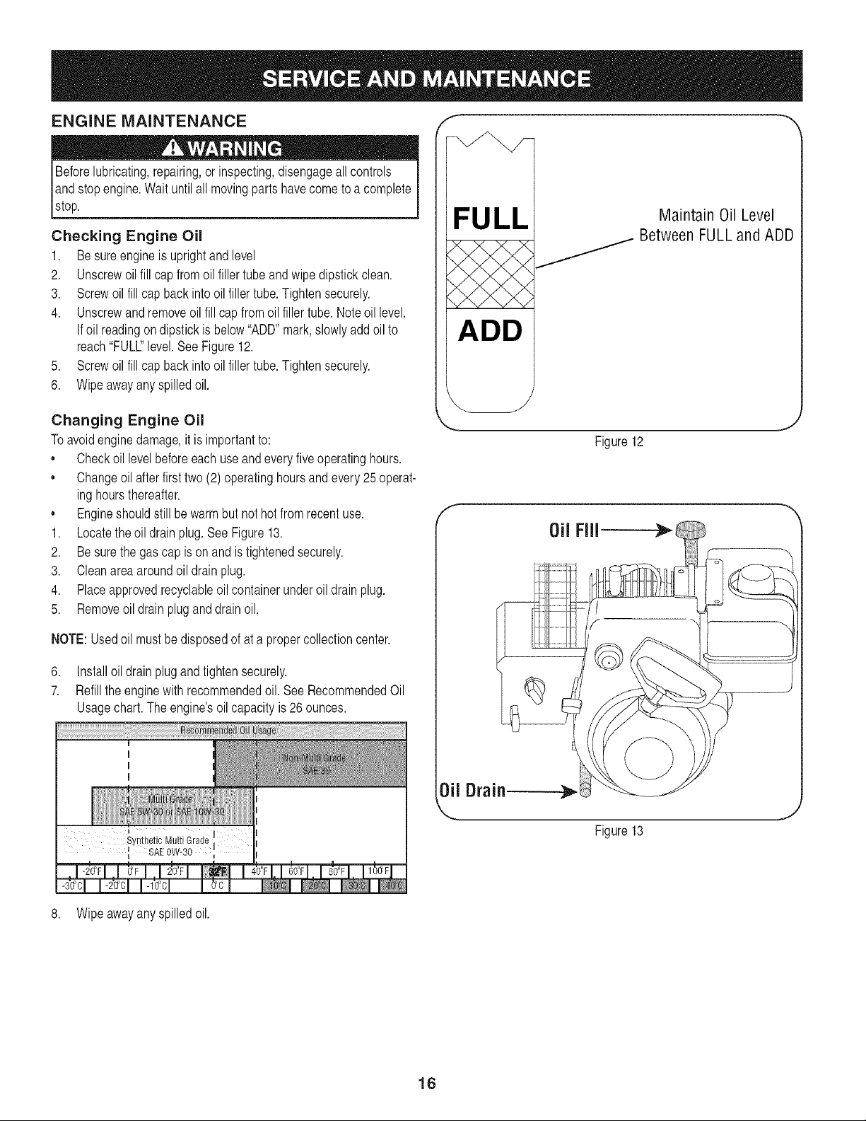
Checking Engine Oil
1. Besureengine isuprightand level
2. Unscrewoil fill capfrom oil fillertubeand wipedipstickclean.
3. Screwoil fill capback into oilfiller tube.Tightensecurely.
4. Unscrewandremoveoilfill cap fromoilfiller tube. Noteoil level.
If oil readingondipstickis below"ADD"mark,slowlyadd oil to
reach"FULL"level.See Figure12.
5. Screwoil fill capback into oilfiller tube.Tightensecurely.
6. Wipeawayany spilledoil.
f .--,,
FULL
ADD
Maintain Oil Level
_ Between FULL and ADD
Changing Engine OH
Toavoidenginedamage,it is importantto:
,, Checkoil levelbeforeeachuse andeveryfiveoperatinghours.
,, Changeoil afterfirst two (2)operatinghoursand every25 operat-
inghoursthereafter.
,, Engineshouldstill be warmbut nothot fromrecentuse.
1. Locatethe oil drain plug.SeeFigure13.
2. Besurethe gas cap is onand istightenedsecurely.
3. Cleanareaaroundoil drain plug.
4. Placeapprovedrecyclableoil containerunderoil drain plug.
5. Removeoil drain plug and drainoil.
NOTE:Usedoil mustbe disposedof at a propercollectioncenter.
6. Installoil drain plugand tightensecurely.
7. Refillthe enginewith recommendedoil. See RecommendedOil
Usagechart.The engine'soilcapacityis 26 ounces.
' I
Synthetic Multi Grade
II SAE OW-30 ",
f
Figure12
0il FIll -.-}t_i
0il Drain
L.
Figure13
J
_J
8. Wipeawayany spilledoil.
16
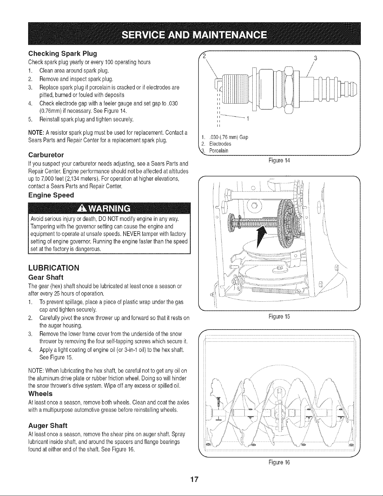
Checking Spark Plug
Checksparkplug yearlyor every 100operatinghours
1. Cleanarea aroundspark plug.
2. Removeand inspectspark plug.
3. Replacespark plug if porcelainis crackedor if electrodesare
pitted,burnedor fouledwith deposits
4. Checkelectrodegap with a feelergaugeandset gapto .030
(0.76ram)if necessary.SeeFigure14.
5. Reinstallspark plugand tightensecurely.
NOTE:A resistorsparkplugmust beusedfor replacement.Contacta
SearsPartsand RepairCenterfor a replacementsparkplug.
Carburetor
If yoususpectyourcarburetorneedsadjusting,seea SearsPartsand
RepairCenter.Engineperformanceshouldnotbe affectedat altitudes
upto 7,000feet (2,134meters).Foroperationat higherelevations,
contacta SearsPartsand RepairCenter.
Engine Speed
Avoidseriousinjuryor death,DO NOTmodifyenginein anyway.
Tamperingwiththegovernorsettingcancausethe engineand
equipmentto operateat unsafespeeds.NEVERtamper with factory
settingof engine governor.Runningthe enginefasterthanthe speed
set at thefactory is dangerous.
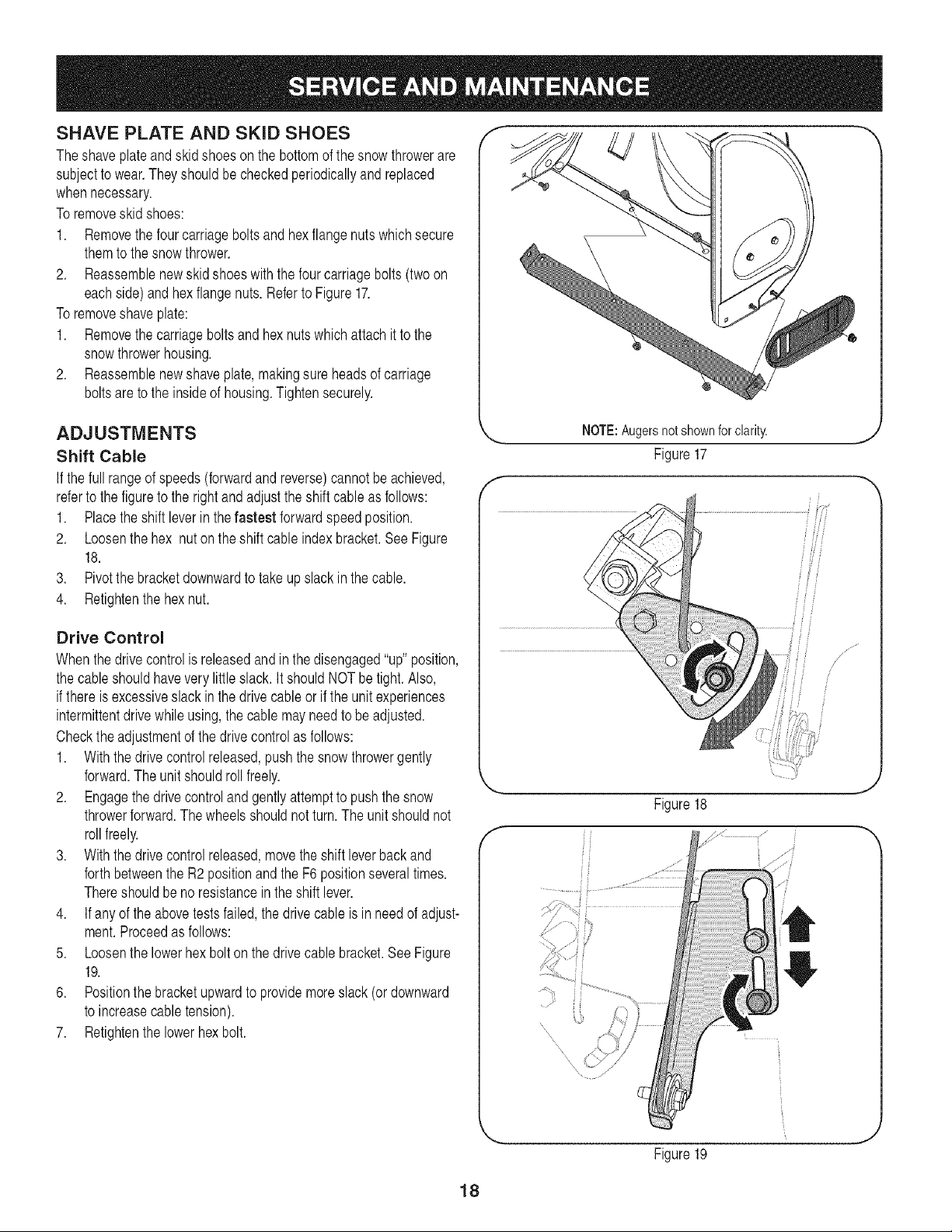
LUBRICATION
Gear Shaft
The gear (hex)shaft shouldbelubricatedat least oncea seasonor
afterevery25 hoursof operation.
1. Topreventspillage,placea pieceof plasticwrap underthegas
capand tightensecurely.
2. Carefullypivot the snowthrowerup andforwardso that it restson
the augerhousing.
3. Removethe lowerframecoverfromthe undersideof the snow
throwerbyremovingthe four self-tappingscrewswhichsecure it.
4. Applya lightcoatingof engineoil (or 3-in-1oil) to the hexshaft.
SeeFigure15.
NOTE:Whenlubricatingthe hexshaft,be carefulnotto get any oil on
the aluminumdriveplateor rubberfrictionwheel.Doingso will hinder
the snowthrower'sdrivesystem.Wipeoff anyexcessor spilledoil.
Wheels
At leastonce a season,removeboth wheels.Cleanand coat the axles
witha multipurposeautomotivegreasebeforereinstallingwheels.
Auger Shaft
At leastonce a season,removethe shearpinson augershaft.Spray
lubricantinsideshaft,and aroundthe spacersand flange bearings
foundat eitherend of the shaft. See Figure16.
3
II
II
1..030 (.76 ram)Gap
2. Electrodes
Porcelain
Figure14
J
\.I
\
\
\
Figure15
/
/ 7
/
J
Figure 16
17
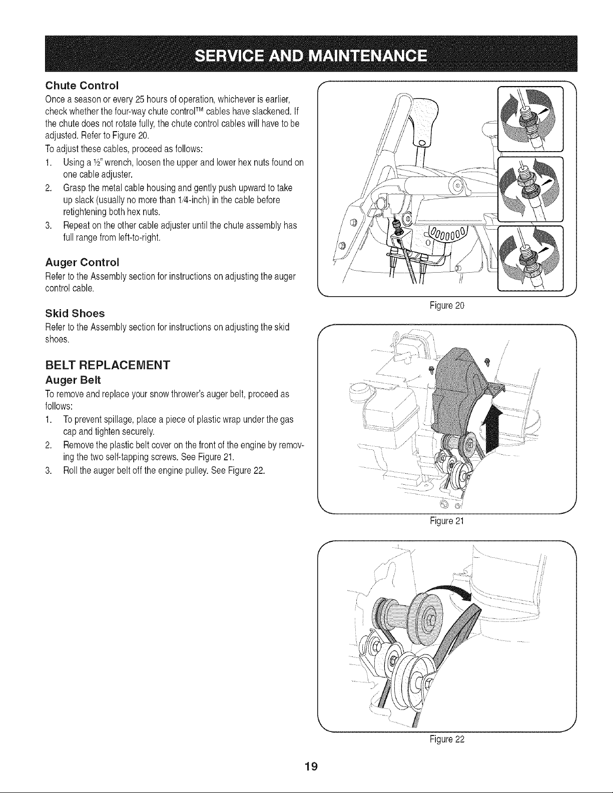
SHAVE PLATE AND SKID SHOES
Theshaveplateand skid shoes on the bottomof the snowthrowerare
subjectto wear.They shouldbe checkedperiodicallyandreplaced
whennecessary.
Toremoveskid shoes:
1. Removethe four carriagebolts and hexflangenuts whichsecure
themto thesnow thrower.
2. Reassemblenewskid shoes with the fourcarriagebolts(two on
eachside) and hexflangenuts.Referto Figure17.
Toremoveshave plate:
1. Removethe carriageboltsand hexnuts whichattach it to the
snowthrowerhousing.
2. Reassemblenewshave plate,makingsure headsof carriage
boltsareto the insideof housing.Tightensecurely.
ADJUSTMENTS
Shift Cable
If the fullrange of speeds(forwardandreverse)cannotbe achieved,
referto the figureto the rightandadjustthe shift cableas follows:
1. Placethe shiftleverin thefastest forwardspeed position.
2. Loosenthe hex nut on the shiftcable indexbracket.SeeFigure
18.
3. Pivotthe bracketdownwardto take up slack in the cable.
4. Retightenthehex nut.
Drive Control
Whenthe drivecontrolis releasedand in thedisengaged"up"position,
the cableshouldhavevery littleslack.It shouldNOTbe tight.Also,
if there is excessiveslackin the drivecableor if the unitexperiences
intermittentdrivewhileusing, thecable mayneedto be adjusted.
Checkthe adjustmentof the drivecontrolas follows:
1. Withthedrive controlreleased,pushthe snow throwergently
forward.The unitshouldrollfreely.
2. Engagethe drivecontrol and gentlyattemptto pushthe snow
throwerforward.The wheelsshouldnot turn.The unitshouldnot
rollfreely.
3. Withthedrive controlreleased,movethe shift leverbackand
forthbetweenthe R2 positionandthe F6 positionseveraltimes.
Thereshouldbe no resistancein the shift lever.
4. If anyof the abovetestsfailed, the drivecableis in needof adjust-
ment.Proceedas follows:
5. Loosenthe lowerhexbolt on the drivecable bracket.See Figure
19.
6. Positionthe bracketupwardto providemoreslack (or downward
to increasecabletension).
7. Retightenthe lowerhex bolt.
',_, NOTE:Augersnotshownforclarity, j
Figure17
if/
iil
f
Figure18
Figure19
/ ....
/
,J
,J
18
Chute Control
Oncea seasonor every 25 hoursof operation,whicheveris earlier,
checkwhetherthe four-waychutecontrolTM cableshaveslackened.If
the chutedoes notrotatefully,the chutecontrol cableswill haveto be
adjusted.Referto Figure20.
To adjustthese cables,proceedas follows:
1. Usinga 1/2"wrench,loosenthe upper and lowerhexnuts foundon
onecableadjuster.
2. Graspthe metalcablehousingand gently pushupwardto take
upslack (usuallyno morethan 1/4-inch)inthe cablebefore
retighteningbothhexnuts.
3. Repeatonthe othercableadjusteruntilthe chuteassemblyhas
full rangefrom left-to-right.
Auger Control
Referto the Assemblysectionfor instructionsonadjustingthe auger
controlcable.
Skid Shoes
Referto the Assemblysectionfor instructionsonadjustingthe skid
shoes.
BELT REPLACEMENT
Auger Belt
To removeand replaceyoursnow thrower'saugerbelt, proceedas
follows:
1. Topreventspillage,placea pieceof plasticwrap underthegas
capand tightensecurely.
2. Removethe plasticbelt coveron thefront of the engineby remov-
ingthe two self-tappingscrews.See Figure21.
3. Rollthe augerbelt off the enginepulley.See Figure22.
f
/
/
Figure20
/
/
/
/
J
f
.......... i ii
iH
J
19
4. Carefullypivot the snowthrowerupand forwardso that it restson
theauger housing.
5. Removethe framecoverfromthe undersideof the snowthrower
by removingfourself-tappingscrewswhichsecureit. SeeFigure
23.
6. Removethe beltas follows.Referto Figure24.
a. Loosenand removetheshoulderscrewwhich actsas a belt
keeper.
b. Unhookthesupport bracketspringfrom theframe.
7. Removethe beltfromaroundthe augerpulley,and slip the belt
betweenthesupport bracketandthe augerpulley.See Figure25.
8. Reassembleaugerbeltby followinginstructionsin reverseorder.
NOTE:Do NOTforgetto reinstallthe shoulderscrewand reconnect
the springto theframe after installinga replacementaugerbelt.
f m
i i
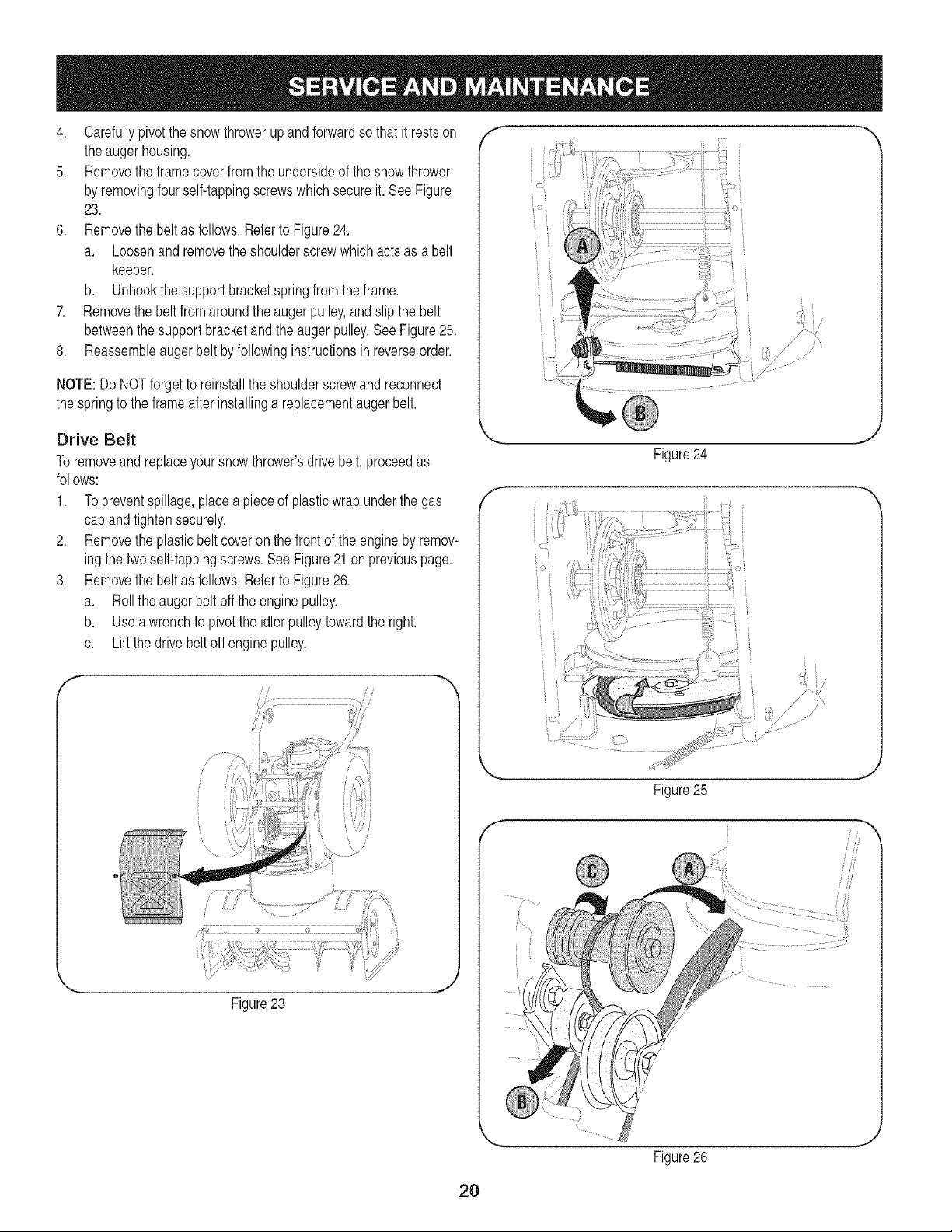
Drive Belt
Toremoveand replaceyoursnowthrower'sdrive belt,proceedas
follows:
1. Topreventspillage,placea pieceof plasticwrap underthe gas
capand tightensecurely.
2. Removethe plasticbeltcoveron the frontof the engineby remov-
ingthe two self-tappingscrews.See Figure21on previouspage.
3. Removethe beltas follows.Referto Figure26.
a. Rollthe augerbelt off the enginepulley.
b. Useawrenchto pivotthe idler pulleytowardthe right.
c. Liftthe drivebelt offenginepulley.
f- ii i
\/
Figure23
f
f
Figure24
• i
Figure25
J
,,J
iii
Figure26
J
2O
4. Carefullypivotthe snowthrowerup andforwardso that it restson
the auger housing.
5. Removethe framecoverfromthe undersideof thesnow thrower
by removingfour self-tappingscrewswhich secureit. Referto
Figure23.
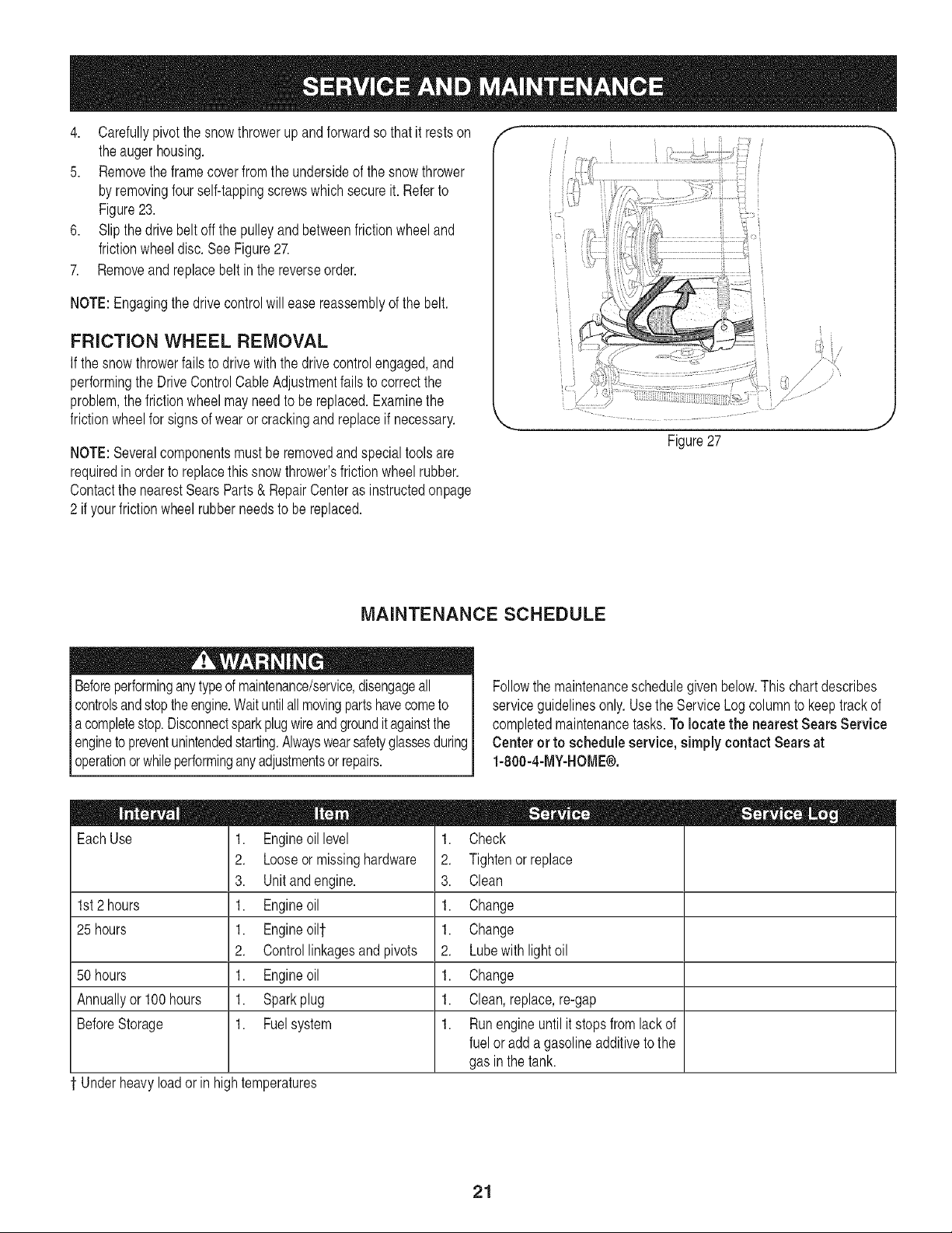
6. Slipthe drivebelt offthe pulleyand betweenfrictionwheeland
frictionwheeldisc.See Figure27.
7. Removeand replacebeltin the reverseorder.
NOTE:Engagingthe drivecontrolwill easereassemblyof the belt.
FRICTION WHEEL REMOVAL
If thesnow throwerfails to drivewith the drivecontrolengaged,and
performingthe DriveControlCableAdjustmentfails to correctthe
problem,the frictionwheelmay needto be replaced.Examinethe
frictionwheelfor signs of wearor crackingandreplaceif necessary.
NOTE:Severalcomponentsmustbe removedandspecialtoolsare
requiredinorderto replacethis snow thrower'sfrictionwheelrubber.
Contactthe nearestSearsParts& RepairCenteras instructedonpage
2 if yourfrictionwheelrubber needsto bereplaced.
f --,,
MAINTENANCE SCHEDULE
Beforeperforminganytypeof maintenance/service,disengageall
controlsand stoptheengine.Waituntilallmovingpartshavecometo
acompletestop.Disconnectsparkplugwireandgroundit againstthe
enginetopreventunintendedstarting.Alwayswearsafetyglassesduring
operationor whileperforminganyadjustmentsor repairs.
Followthe maintenanceschedulegivenbelow.This chart describes
serviceguidelinesonly.Usethe ServiceLog columnto keeptrackof
completedmaintenancetasks.To locate the nearest Sears Service
Center or to schedule service,simplycontactSears at
1-800-4-MY-HOME®.
EachUse
1st2 hours
25 hours
50 hours
Annuallyor 100 hours
BeforeStorage
' Underheavyloador inhightemperatures
1. Engineoillevel
2. Looseor missinghardware
3. Unitandengine.
1. Engineoil
1. Engineoi11
2. Controllinkagesand pivots
1. Engineoil
1. Sparkplug
1. Fuelsystem
1. Check
2. Tightenor replace
3. Clean
1. Change
1. Change
2. Lubewith lightoil
1. Change
1. Clean,replace,re-gap
1. Runengineuntil it stopsfrom lackof
fuel or add a gasolineadditiveto the
gas in thetank.
21
If the snowthrowerwill notbe usedfor 30daysor longer,or if it is the end of the snowseasonwhenthe lastpossibilityof snow isgone,the
equipmentneedsto be stored properly.Followstorageinstructionsbelowto ensuretop performancefromthe snow throwerfor manymoreyears.
PREPARING ENGINE
Short=Term Storage
It is importantto preventgumdepositsfromforminginessentialfuel
systemparts of the enginesuch as the carburetor,fuel filter,fuel hose,
ortankduringshort-termstorage(15-30days).To preventthis,treat
the fuelsystemusinga fuel stabilizer.
Fuelstabilizer(suchas STA-BILTM or ULTRA-FRESHTM) is an accept-
ablealternativein minimizingthe formationof fuelgum depositsduring
storage.Add stabilizerto gasolinein fueltank or storagecontainer.
Alwaysfollow mix ratiofoundon stabilizercontainer.Runengine at
least10minutesafter addingstabilizerto allowit to reachthe carbure-
tor.
Neverstoresnowthrowerwithfuel in tank indoorsor in poorlyventi-
latedareas,wherefuelfumesmay reachan openflame,spark or pilo
ght as on afurnace,water heater,clothesdryer or gas appliance.
PREPARING SNOW THROWER
,, Whenstoringthe snowthrowerin an unventilatedor metalstor-
ageshed,careshouldbe taken to rustproofthe equipment.Using
a light oil or silicone,coatthe equipment,especiallyanychains,
springs,bearingsandcables.
,, Removeall dirt fromexteriorof engineand equipment.
,, Followlubricationrecommendations.
,, Storeequipmentin a clean,dry area.
Alcoholblendedfuels (calledgasoholor usingethanolor methanol)
canattract moisturewhichleadsto separationandformationof acids
duringstorage.Acidicgas can damagethe fuelsystemof an engine
[wh e n storage.
Long=Term Storage
Toavoidengineproblems,thefuel systemshouldbeemptiedbefore
storagefor 30daysor longer.
Fuelleft in engineduringwarm weatherdeterioratesandwill cause
seriousstartingproblems.
J
1. Runthe engineuntil thefuel tank is emptyandit stops due to lack
of fuel. Do notattemptto pourfuel fromthe engine.
pNeveruseengineor cleaningproducts or
/
carburetor inthe fueltank
ermanentdamagemayoccur, j
2. Removethe spark plugandpourone (1)ounceof engineoil
throughthe sparkplug holeintothe cylinder.Coversparkplughole
witha ragandcrankthe engineseveraltimesto distributethe oil.
Replacesparkplug.
22
Beforeperforminganytypeof maintenance/service,disengageall
controlsandstoptheengine.Waituntilall movingpartshavecometo
a completestop.Disconnectsparkplugwireandgrounditagainstthe
engineto preventunintendedstarting.Alwayswearsafetyglassesdurin(
operationor whileperforminganyadjustmentsorrepairs.
Thissectionaddressesminor service issues,Tolocatethe nearestSears Service Center or to scheduleservice,simply contactSears
at 1-800-4-MY-HOME®.
Enginefailsto start
o =
1. Chokecontrolnot in ONposition
2. Sparkplug wiredisconnected
3. Faultyspark plug
4. Fueltank emptyor stale fuel
5. Enginenot primed.
6. Safetykey not inserted.
1. Enginerunningon CHOKE
2. Stalefuel
3. Wateror dirt in fuel system
4. Carburetoroutof adjustment
1. Carburetornotadjustedproperly
1. Looseparts or damagedauger
Enginerunserratically
Engineoverheats
Excessivevibration
Lossof power 1. Sparkplug wireloose.
2. Gas capvent hole plugged.
Unitfailsto propelitself 1. Drivecablein needof adjustment
2. Drivebelt looseor damaged
Unitfailsto dischargesnow 1. Chuteassemblyclogged.
2. Foreignobject lodged in auger.
3. Augercable in need of adjustment.
4. Augerbelt looseor damaged.
5. Shearpin(s) sheared.
1. Movechokecontrolto ON position.
2. Connectwire to spark plug.
3. Clean,adjustgap,or replace.
4. Fill tank with clean,fresh gasoline.
5. Primeengineas instructedin the OperationSection.
6. Insert keyfully intothe switch.
1. Movechokecontrolto OFF position.
2. Fill tank with clean,fresh gasoline.
3. Drainfuel tank.Refillwith freshfuel.
4. ContactyourSearsParts & RepairCenter.
1. ContactyourSearsParts & RepairCenter.
1. Stopengine immediatelyand disconnectspark plug
wire.Tightenall boltsandnuts.If vibrationcontinues,
haveunit servicedby a SearsParts& RepairCenter.
1. Connectand tighten sparkplug wire.
2. Removeice andsnowfromgas cap. Be certainvent
holeis clear.
1. Adjustdrivecontrolcable. Referto Serviceand
Maintenancesection.
2. Replacedrivebelt. Referto Serviceand Mainte-
nancesection.
1. Stopengine immediatelyand disconnectspark plug
wire.Cleanchute assemblyand insideof auger
housingwith clean-outtool ora stick.
2. Stopengine immediatelyand disconnectspark plug
wire.Removeobject from augerwith clean-outtool
or a stick.
3. Adjustaugercontrolcable.Referto Assembly
section.
4. Replaceaugerbelt.Referto ServiceandMainte-
nancesection.
5. Replacewithnewshearpin(s).
23
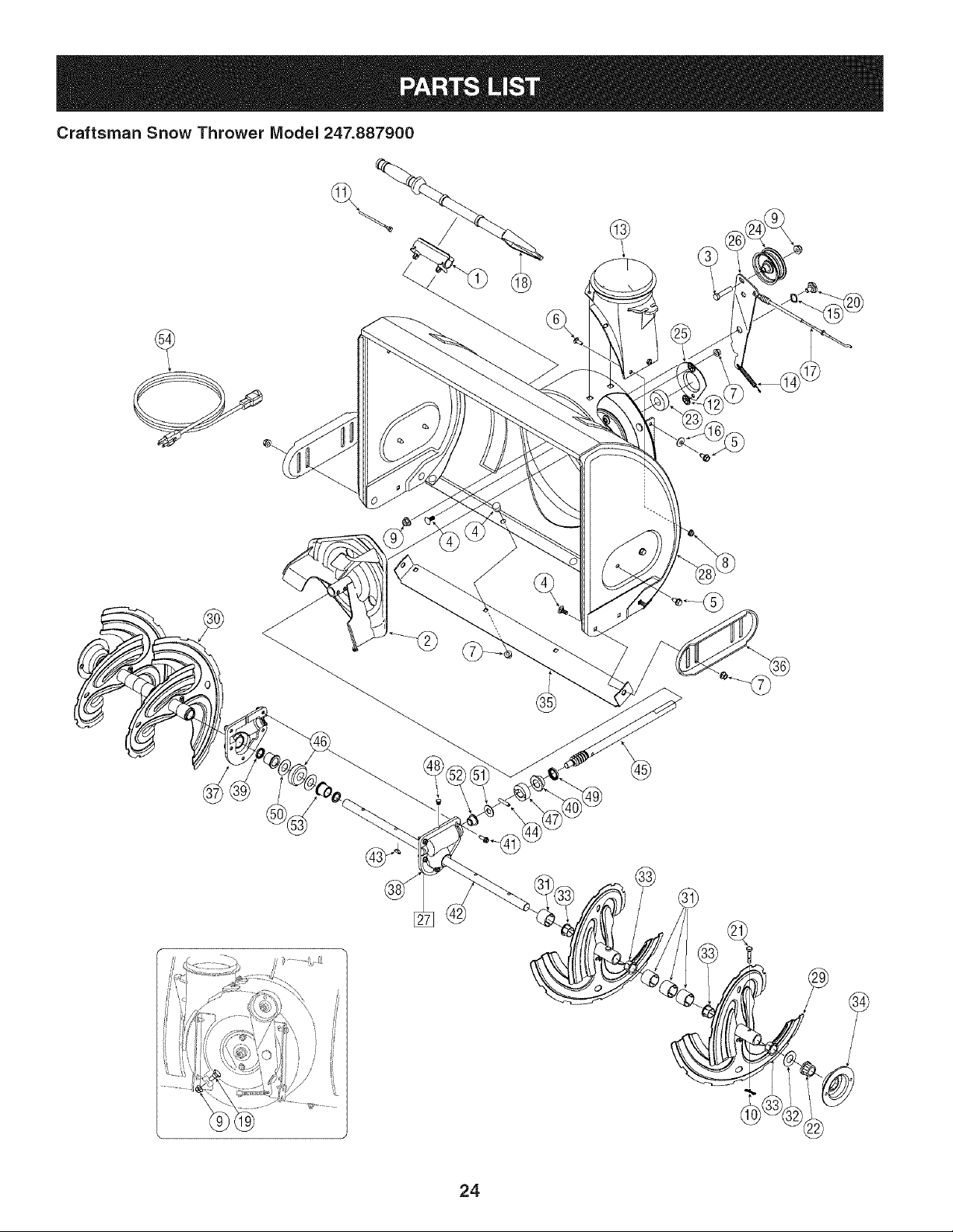
Craftsman Snow Thrower IVlodel 247.887900
9
24
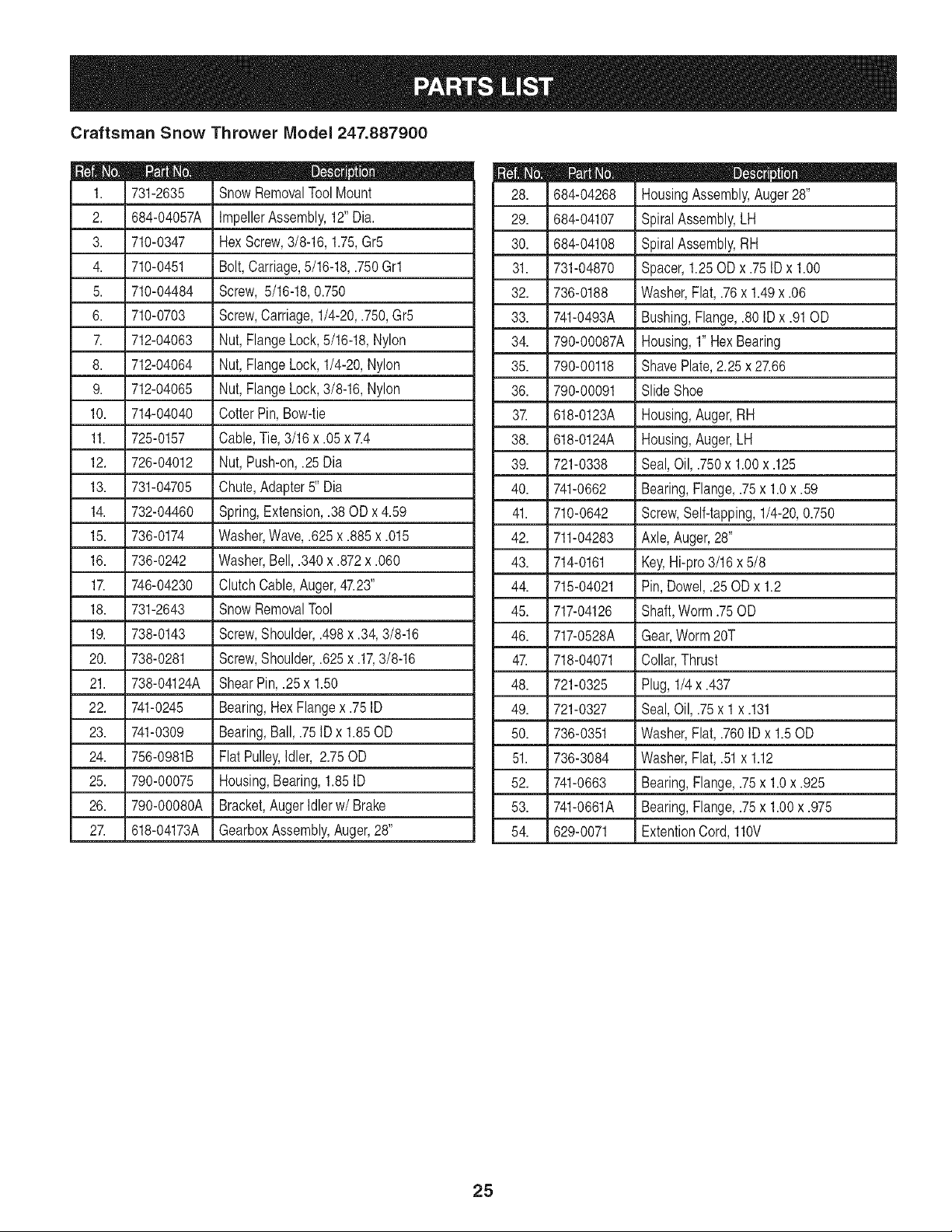
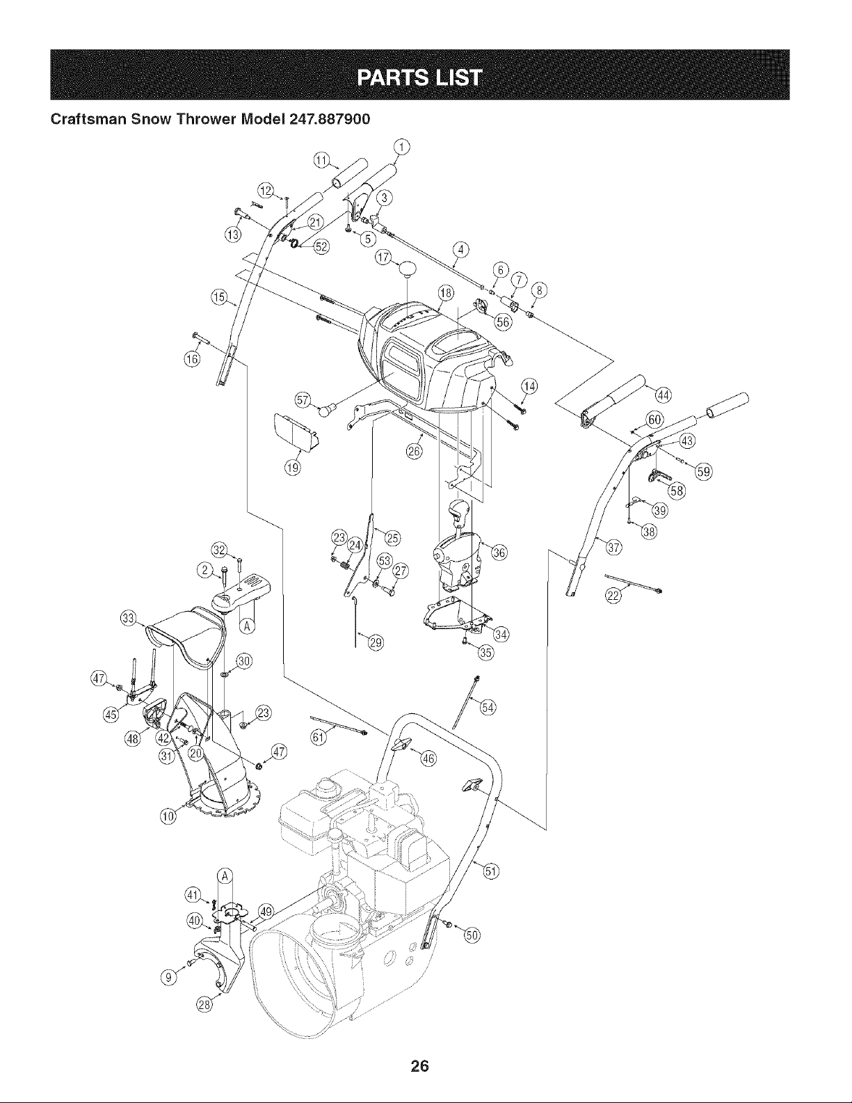
Craftsman Snow Thrower Model 247.887900
731-2635
2. 684-04057A
3. 710-0347
4. 710-0451
5. 710-04484
6. 710-0703
712-04063
8. 712-04064
9. 712-04065
10. 714-04040
11. 725-0157
12. 726-04012
13. 731-04705
14. 732-04460
15. 736-0174
16. 736-0242
1_ 746-04230
18. 731-2643
19. 738-0143
20. 738-0281
21. 738-04124A
22. 741-0245
23. 741-0309
24. 756-0981B
25. 790-00075
26. 790-00080A
2_ 618-04173A
SnowRemovalToolMount
ImpellerAssembly,12"Dia.
HexScrew,3/8-16, 1.75,Gr5
Bolt,Carriage,5/16-18,.750Grl
Screw, 5/16-18,0.750
Screw,Carriage,1/4-20,.750,Gr5
Nut,FlangeLock,5/16-18,Nylon
Nut,FlangeLock,1/4-20,Nylon
Nut,FlangeLock,3/8-16,Nylon
CotterPin, Bow-tie
Cable,Tie,3/16 x .05 x 7.4
Nut,Push-on,.25Dia
Chute,Adapter5" Dia
Spring,Extension,.38 OD x 4.59
Washer,Wave,.625x .885x .015
Washer,Bell,.340 x .872x .060
ClutchCable,Auger,47.23"
SnowRemovalTool
Screw,Shoulder,.498x .34,3/8-16
Screw,Shoulder,.625x .17,3/8-16
ShearPin,.25 x 1.50
Bearing,HexFlangex .75 ID
Bearing,Ball,.75ID x 1.85OD
FlatPulley,Idler, 2.75OD
Housing,Bearing,1.85ID
Bracket,AugerIdlerw/Brake
GearboxAssembly,Auger,28"
684-04268
29. 684-04107
30. 684-04108
31. 731-04870
32. 736-0188
33. 741-0493A
34. 790-00087A
35. 790-00118
36. 790-00091
3Z 618-0123A
38. 618-0124A
39. 721-0338
40. 741-0662
41. 710-0642
42. 711-04283
43. 714-0161
44. 715-04021
45. 717-04126
46. 717-0528A
4_ 718-04071
48. 721-0325
49. 721-0327
50. 736-0351
51. 736-3084
52. 741-0663
53. 741-0661A
54. 629-0071
D _ O Q
HousingAssembly,Auger 28"
SpiralAssembly,LH
SpiralAssembly,RH
Spacer,1.25OD x .75IDx 1.00
Washer,Flat, .76x 1.49x .06
Bushing,Flange,.80 ID x .91OD
Housing,1" HexBearing
ShavePlate,2.25 x 27.66
SlideShoe
Housing,Auger,RH
Housing,Auger,LH
Seal,Oil, .750x 1.00x .125
Bearing,Flange,.75x 1.0x .59
Screw,Self-tapping,1/4-20,0.750
Axle,Auger,28"
Key,Hi-pro3/16x 5/8
Pin, Dowel,.25 ODx 1.2
Shaft,Worm.75OD
Gear,Worm20T
Collar,Thrust
Plug, 1/4x .437
Seal,Oil, .75x 1 x .131
Washer,Flat, .760IDx 1.50D
Washer,Flat, .51x 1.12
Bearing,Flange,.75x 1.0x .925
Bearing,Flange,.75x 1.00x .975
ExtentionCord, 110V
25
Craftsman Snow Thrower IVlodel 247.887900
/
26
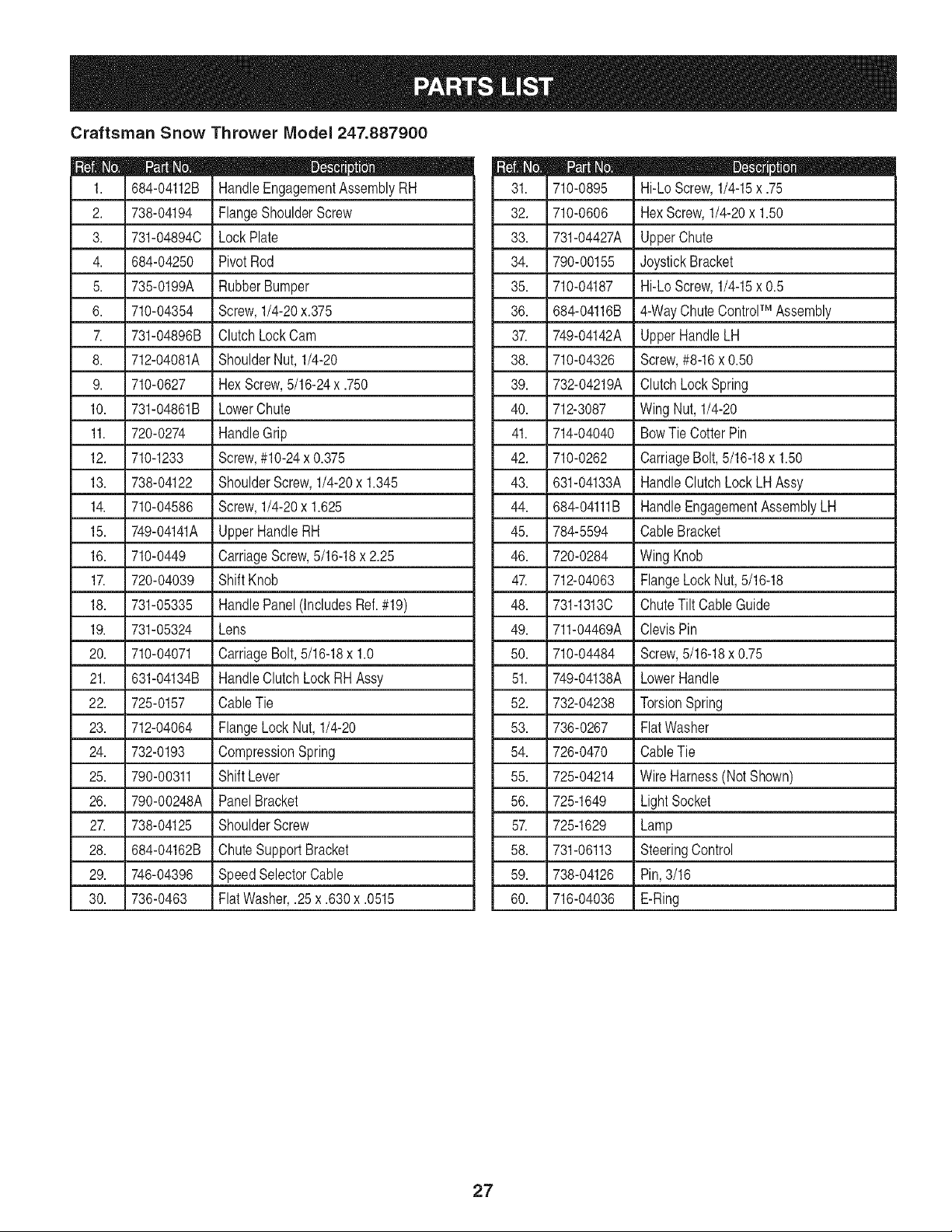
Craftsman Snow Thrower Model 247.887900
D _ _ m
684-04112B HandleEngagementAssemblyRH
2. 738-04194 FlangeShoulderScrew
3. 731-048940 LockPlate
4. 684-04250 Pivot Rod
5. 735-0199A RubberBumper
6. 710-04354 Screw,1/4-20x.375
7. 731-04896B ClutchLockCam
8. 712-04081A ShoulderNut, 1/4-20
9. 710-0627 Hex Screw,5/16-24x .750
10. 731-04861B LowerChute
11. 720-0274 HandleGrip
12. 710-1233 Screw,#10-24x 0.375
13. 738-04122 ShoulderScrew,1/4-20x 1.345
14. 710-04586 Screw,1/4-20x 1.625
15. 749-04141A UpperHandleRH
16. 710-0449 CarriageScrew,5/16-18x 2.25
17. 720-04039 Shift Knob
18. 731-05335 HandlePanel(IncludesRef.#19)
19. 731-05324 Lens
20. 710-04071 CarriageBolt,5/16-18x 1.0
21. 631-04134B HandleClutchLockRHAssy
22. 725-0157 CableTie
23. 712-04064 FlangeLockNut,1/4-20
24. 732-0193 CompressionSpring
25. 790-00311 ShiftLever
26. 790-00248A PanelBracket
27. 738-04125 ShoulderScrew
28. 684-04162B ChuteSupportBracket
29. 746-04396 SpeedSelectorCable
30. 736-0463 Flat Washer,.25x .630x .0515
710-0895 Hi-LoScrew,1/4-15x .75
32. 710-0606 HexScrew,1/4-20x 1.50
33. 731-04427A UpperChute
34. 790-00155 JoystickBracket
35. 710-04187 I Hi-LoScrew,1/4-15x 0.5
36. 684-04116B 4-WayChuteControlTM Assembly
37. 749-04142A UpperHandleLH
38. 710-04326 i Screw,#8-16x0.50
39. 732-04219A i ClutchLockSpring
40. 712-3087 l Wing Nut,1/4-20
41. 714-04040 BowTie CotterPin
I
42. 710-0262 CarriageBolt,5/16-18x 1.50
43. 631-04133A HandleClutchLockLHAssy
44. 684-04111B HandleEngagementAssemblyLH
45. 784-5594 i CableBracket
46. 720-0284 i Wing Knob
47. 712-04063 FlangeLockNut,5/16-18
48. 731-13130 i ChuteTilt CableGuide
49. 711-04469A ClevisPin
50. 710-04484 i Screw,5/16-18x 0.75
51. 749-04138A LowerHandle
52. 732-04238 I TorsionSpring
53. 736-0267 FlatWasher
54. 726-0470 CableTie
55. 725-04214 Wire Harness(Not Shown)
56. 725-1649 LightSocket
57. 725-1629 i Lamp
58. 731-06113 SteeringControl
59. 738-04126 I Pin,3/16
60. 716-04036 i E-Ring
27
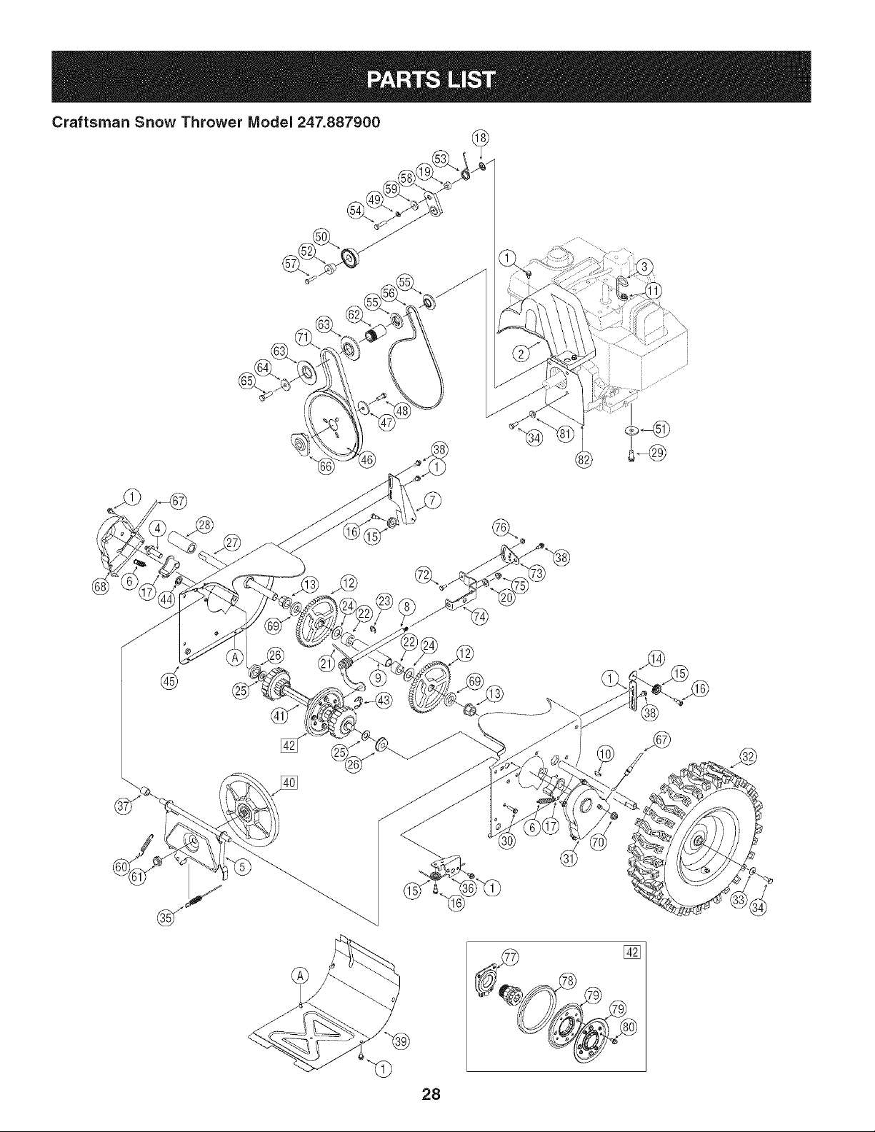
Craftsman Snow Thrower IVlodel 247.887900
28
D _ Q Q
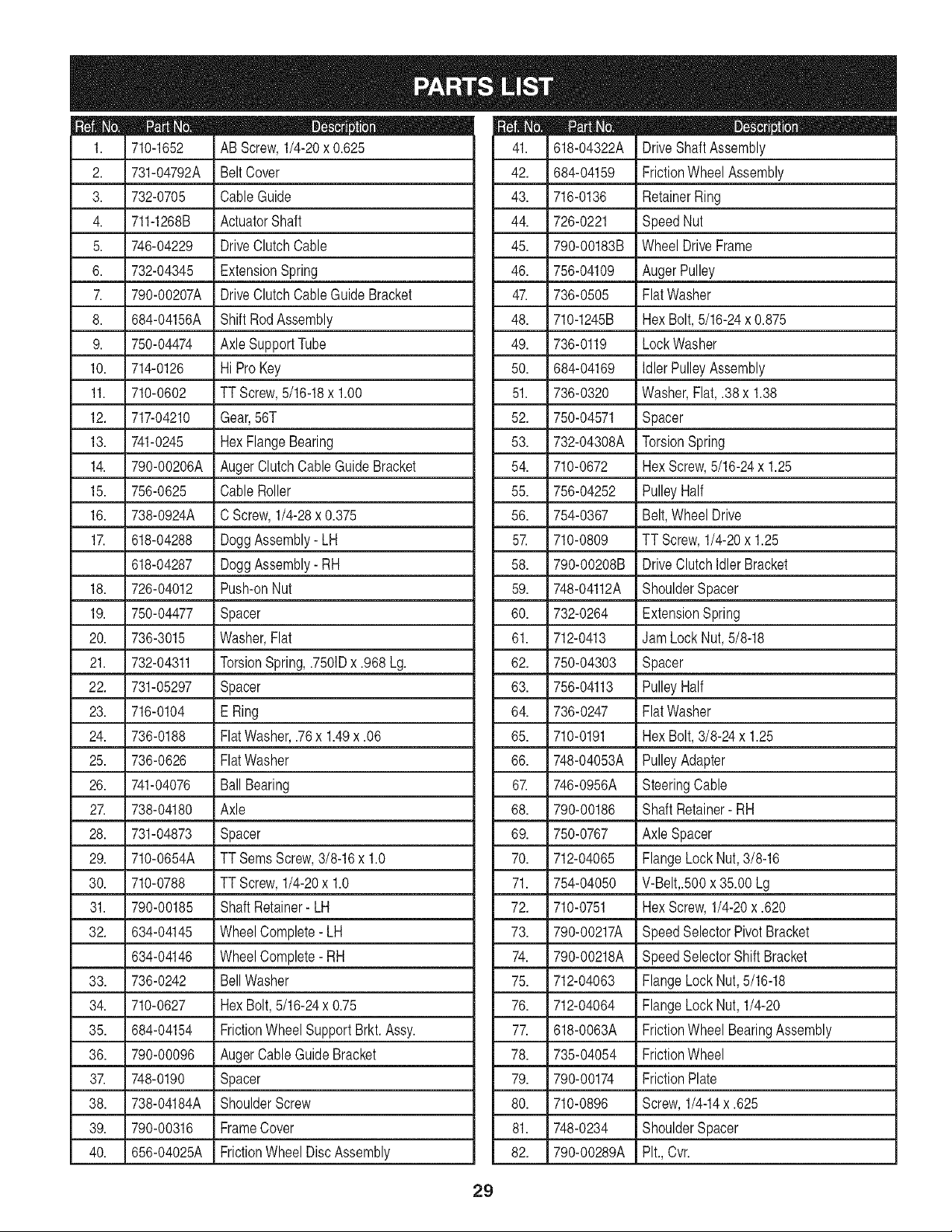
710-1652 AB Screw,1/4-20x 0.625
2. 731-04792A Belt Cover
3. 732-0705 CableGuide
4. 711-1268B ActuatorShaft
5. 746-04229 DriveClutchCable
6. 732-04345 ExtensionSpring
7. 790-00207A DriveClutchCableGuide Bracket
8. 684-04156A Shift RodAssembly
9. 750-04474 Axle SupportTube
10. 714-0126 Hi ProKey
11. 710-0602 TT Screw,5/16-18x 1.00
12. 717-04210 Gear,56T
13. 741-0245 HexFlangeBearing
14. 790-00206A AugerClutchCableGuide Bracket
15. 756-0625 CableRoller
16. 738-0924A C Screw,1/4-28x 0.375
17. 618-04288 DoggAssembly- LH
618-04287 DoggAssembly- RH
18. 726-04012 Push-onNut
19. 750-04477 Spacer
20. 736-3015 Washer,Flat
21. 732-04311 TorsionSpring,.7501Dx .968Lg.
22. 731-05297 Spacer
23. 716-0104 E Ring
24. 736-0188 FlatWasher,.76x 1.49x .06
25. 736-0626 FlatWasher
26. 741-04076 Ball Bearing
27. 738-04180 Axle
28. 731-04873 Spacer
29. 710-0654A TT SemsScrew,3/8-16x 1.0
30. 710-0788 TT Screw,1/4-20x 1.0
31. 790-00185 ShaftRetainer- LH
32. 634-04145 WheelComplete- LH
634-04146 WheelComplete- RH
33. 736-0242 BellWasher
34. 710-0627 HexBolt,5/16-24x 0.75
35. 684-04154 FrictionWheelSupportBrkt.Assy.
36. 790-00096 AugerCableGuideBracket
37. 748-0190 Spacer
38. 738-04184A ShoulderScrew
39. 790-00316 FrameCover
40. 656-04025A FrictionWheelDisc Assembly
D _ O Q
618-04322A DriveShaftAssembly
42. 684-04159 FrictionWheelAssembly
43. 716-0136 RetainerRing
44. 726-0221 SpeedNut
45. 790-00183B Wheel DriveFrame
46. 756-04109 AugerPulley
47. 736-0505 FlatWasher
48. 710-1245B HexBolt,5/16-24x 0.875
49. 736-0119 LockWasher
50. 684-04169 IdlerPulleyAssembly
51. 736-0320 Washer,Flat,.38 x 1.38
52. 750-04571 Spacer
53. 732-04308A TorsionSpring
54. 710-0672 HexScrew,5/16-24x 1.25
55. 756-04252 PulleyHalf
56. 754-0367 Belt,WheelDrive
57. 710-0809 TT Screw,1/4-20x 1.25
58. 790-00208B DriveClutchldler Bracket
59. 748-04112A ShoulderSpacer
60. 732-0264 ExtensionSpring
61. 712-0413 Jam LockNut,5/8-18
62. 750-04303 Spacer
63. 756-04113 PulleyHalf
64. 736-0247 FlatWasher
65. 710-0191 HexBolt,3/8-24 x 1.25
66. 748-04053A PulleyAdapter
67. 746-0956A SteeringCable
68. 790-00186 Shaft Retainer- RH
69. 750-0767 Axle Spacer
70. 712-04065 FlangeLock Nut,3/8-16
71. 754-04050 V-Belt,.500x 35.00 Lg
72. 710-0751 HexScrew,1/4-20x .620
73. 790-00217A SpeedSelectorPivotBracket
74. 790-00218A SpeedSelectorShift Bracket
75. 712-04063 FlangeLock Nut,5/16-18
76. 712-04064 FlangeLock Nut, 1/4-20
77. 618-0063A FrictionWheelBearingAssembly
78. 735-04054 FrictionWheel
79. 790-00174 FrictionPlate
80. 710-0896 Screw,1/4-14x .625
81. 748-0234 ShoulderSpacer
82. 790-00289A Pit.,Cvr.
29
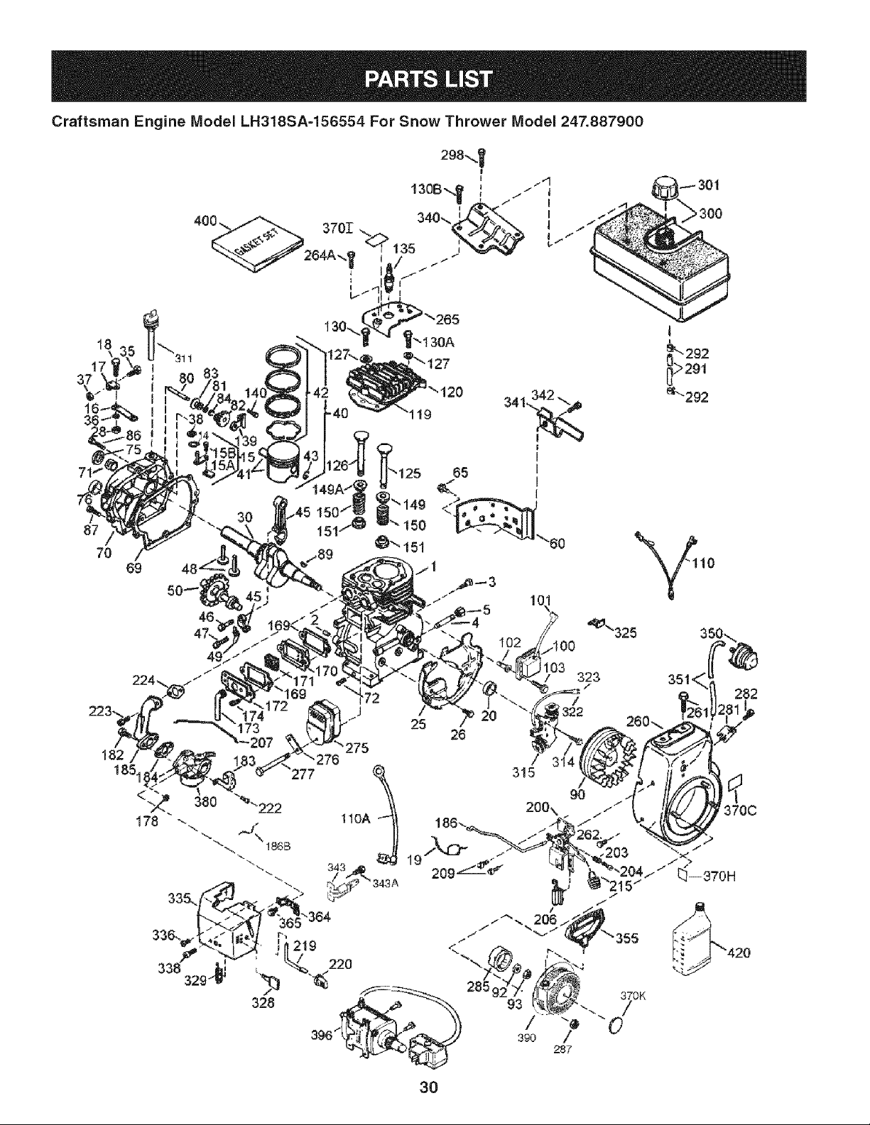
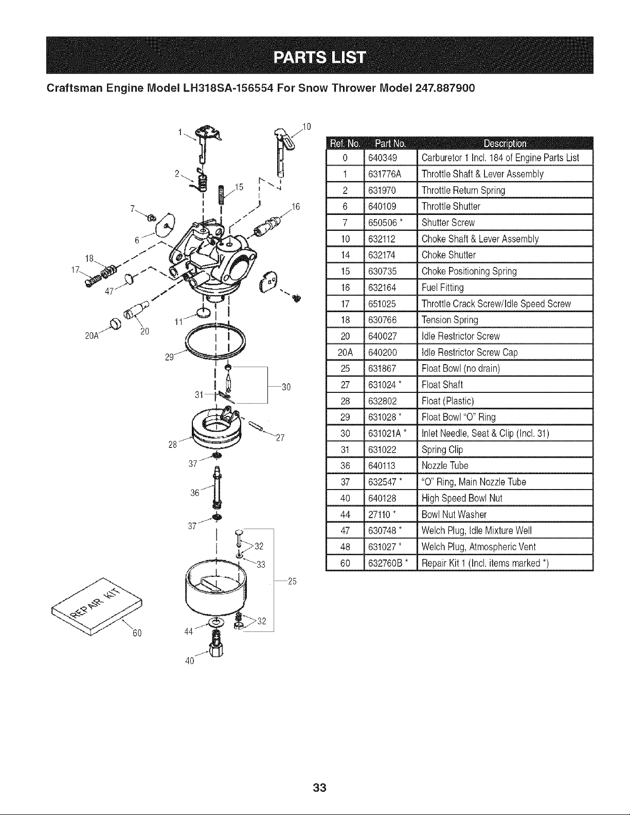
Craftsman Engine Model LH318SA-156554 For Snow Thrower Model 247.887900
87
70
69
10
182
207
277
1IOA
t
i
292
_>291
et--.292
2O
25
26
315
30
Craftsman Engine Model LH318SA=156554 For Snow Thrower Model 247.887900
m
1.
2.
3.
5.
14.
15.
15B.
16.
17.
18.
19.
20.
25.
26.
28.
30.
35.
36.
37.
38.
40.
40.
41.
41.
42.
42.
43.
45.
47.
48.
49.
50.
60.
65.
69.
70.
71.
72.
75.
76.
m
35385
27652
650820
30969
28277
30699C
650494
33454A
29916
651028
34663
35319
37853
650561
30322
35980A
29826
29918
29216
29642
40011
40012
40009
40010
40013
40014
27888
36897
651033
34034
36896
36655
33273A
650128
37342
35445B
35377
27642
35319
28926
D _ Q 0"
Cylinder
DowelPin
Screw,1/4-20x 0.5"
ExtensionCap
Washer
GovernorRod
Screw,6-40 x 5/16"
GovernorLever
GovernorLeverClamp
Screw,T-15,8-32 x 7/16"
SpeedControlSpring
Oil Seal
BlowerHousingBaffle
Screw,1/4-20x 19/32"
LockNut, 8-32
Crankshaft
Screw,10-32x 3/4"
LockWasher
LockNut, 10-32
RetainingRing
Piston,Pin & RingSet (Std.)
Piston,Pin & RingSet (.010"OS)
Piston,Pin & RingSet (Std.incl.43)
Piston,Pin & RingSet (.010"OSincl.43)
RingSet(Std.)
RingSet(.010"OS)
PistonPinRetainingRing
ConnectingRodAssembly(incl.47 & 49)
ConnectingRodBolt
ValveLifter
Oil Dipper
Camshaft(MCR)
BlowerHousingExtension
Screw,10-24x 1/2"
CylinderCoverGasket
CylinderCover(Incl. 71,75,76,80-84)
CrankshaftBushing
Oil DrainPlug
Oil Seal
CamshaftSeal
m
80.
81.
82.
83.
84.
86.
87.
89.
90.
92.
93.
100.
101.
102.
103.
110.
110A.
119.
120.
125.
125.
126.
127.
130.
130A.
130B.
135.
139.
140.
149.
149A.
150.
151.
169.
170.
171.
172.
173.
174.
178.
37587
651080
37588
30588A
29193
650833
650832
32589
611093
650880
650881
35135A
610118
651024
651007
35187
37047
36448
36449
27878A
27880A
34035
650691
6021A
650727
651055
35395
33369
650836
27882
35862
27881
32581
27896A
28423
28424
28425
35350
650128
29752
D_ 0 0
GovernorShaft
Washer
GovernorGear Ass'y.(Incl.81)
GovernorSpool
RetainingRing
Screw,1/4-20x 1-3/16"
Screw,1/4-20x 1-11/16"
FlywheelKey
Flywheel(W/RingGear)
LockWasher
FlywheelNut
SolidStateIgnition(Incl. 101)
SparkPlugCover
SolidStateMountingStud
Screw,T-15,10-24x 15/16"
GroundWire
GroundWire
CylinderHeadGasket
CylinderHead
ExhaustValve(Std.incl.151)
ExhaustValve(1/32"OS inc1.151)
IntakeValve(Std.)(Incl. 151)
Washer
Screw,5/16-18x 1-1/2"
Screw,5/16-18x 1-25/32"
Screw,5/16-18x 39/64"
ResistorSparkPlug (RJ19LM)
GovernorGear Bracket
Screw,10-24x 1/2"
ValveSpringCap
ValveSpringCap
ValveSpring
ValveSpringKeeper
ValveCoverGasket
BreatherBody
BreatherElement
ValveCover
BreatherTube
Screw,10-24x 1/2"
Nut& LockWasher,1/4-28
31
Craftsman Engine Model LH318SA-156554 For Snow Thrower Model 247.887900
30088A
183. 34587A
184. 33263
185. 33877
186. 34667
186B. 36652
200. 34677
203. 31342
204. 651029
206. 610973
20_ 33878
209. 650821
215. 35440
219. 34586
220. 35438
222. 28820
223. 650378
224. 27915A
260. 35447A
261. 650788
262. 651084
264A. 650802
265. 33272D
275. 35056
276. 31588
27_ 651002
281. 33013
282. 650760
285. 35985B
28_ 29752
291. 30962
292. 26460
298. 650665
Screw,1/4-28x 1"
ChokeBracket
CarburetorTo IntakePipeGasket
IntakePipe
GovernorLink
ChokeSpring
ControlBracket(Incl. 19,203,204 & 206)
CompressionSpring
Screw,T-IO,5-40 x 7/16"
Terminal
ThrottleLink
Screw,10-32x 1/2"
ControlKnob
ChokeRod
ChokeKnob
Screw,10-32x 1/2"
Screw,T-30, 5/16-18x 1-3/32"
IntakePipe Gasket
BlowerHousing
Screw,5/16-18x 3/4"
Screw,5/16-18x 9/16"
Screw,1/4-20x 5/8"
CylinderHeadCover(Black)
Muffler
LockingPlate
Screw,5/16-18x 4-3/16"
StarterBubbleCover
Screw,8-32 x 3/8"
StarterCup
Nut& LockWasher,1/4-28
FuelLine
FuelLineClamp
Screw,1/4-15x 7/8"
300.
301.
311.
314.
315.
322.
323.
325.
328.
329.
335.
336.
338.
340.
341.
342.
343.
343A.
350.
351.
355.
364.
365.
3700.
370H.
3701.
370K.
380.
390.
396.
400.
420.
34186A
35355
35942
650873
611111
611117
611118
29443
35062
610973
36547
650765
28942
34154
34155
650561
35079A
651060
570682A
321800
590574
37659
650767
36501
35077
37119
36695
640052
590749
33329E
364500
730226A
D _ _ 0
FuelTank(Incl.292 & 301)
FuelCap
Oil FillPlug
Screw,1/4-20x 3/4"
AlternatorCoil (18Watt)(Incl. 322&323)
ConnectorBody
Terminal
WireClip
IgnitionKeys
Terminal
CarburetorCover
Screw,10-32 x 1/2"
Screw,10-32 x 3/8"
FuelTankBracket
FuelTankBracket
Screw,1/4-20x 19/32"
KeySwitchBracket(Incl.343A)
Screw,10-32 x 23/64"
PrimerAss'y.
PrimerLine
StarterHandle
CarburetorCoverBracket
Screw,8-32 x 27/64"
PrimerDecal
ChokeDecal
WarningDecal
StarterDecal
Carburetor(Incl. 184)
RewindStarter
ElectricStarterMotor(Optional)
GasketSet
SAE5W30,4-Cycle EngineOil (Quart)
32
Craftsman Engine Model LH318SA-156554 For Snow Thrower Model 247.887900
60
30
25
640349
1 631776A
2 631970
6 640109
7 650506 *
10 632112
14 632174
15 630735
16 632164
17 651025
18 630766
20 640027
20A 640200
25 631867
27 631024*
28 632802
29 631028*
30 631021A*
31 631022
36 640113
37 632547*
40 640128
44 27110*
47 630748*
48 631027*
60 632760B*
D _ e Q
Carburetor1 Incl. 184of EnginePartsList
ThrottleShaft & LeverAssembly
ThrottleReturnSpring
ThrottleShutter
ShutterScrew
ChokeShaft& LeverAssembly
ChokeShutter
ChokePositioningSpring
FuelFitting
ThrottleCrackScrew/IdleSpeedScrew
TensionSpring
IdleRestrictorScrew
IdleRestrictorScrewCap
FloatBowl(no drain)
FloatShaft
Float(Plastic)
FloatBowl"0" Ring
InletNeedle,Seat& Clip(Incl. 31)
SpringClip
NozzleTube
"0" Ring, MainNozzleTube
HighSpeedBowlNut
BowlNut Washer
WelchPlug,IdleMixtureWell
WelchPlug,AtmosphericVent
RepairKit 1 (Incl.itemsmarked*)
33
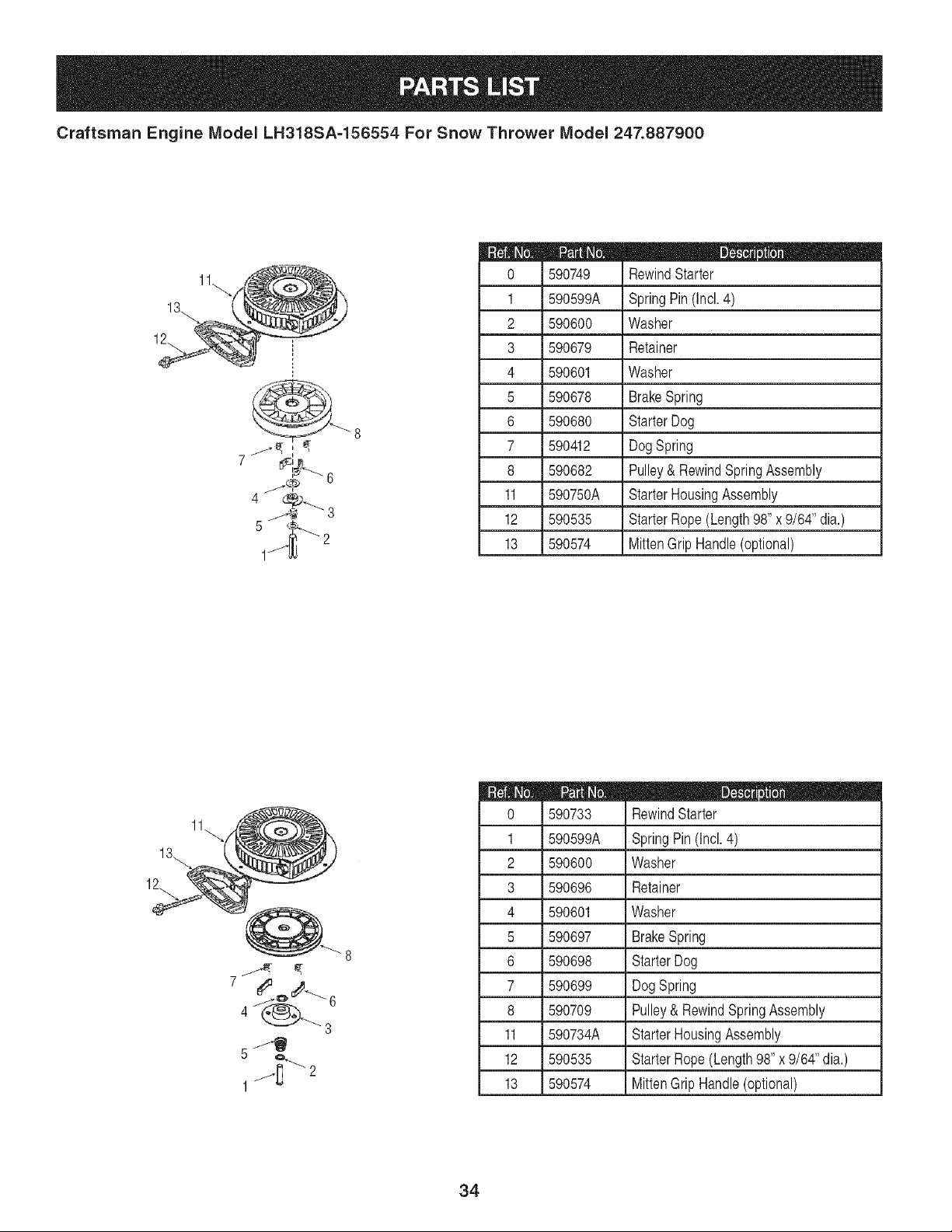
Craftsman Engine Model LH318SA=156554 For Snow Thrower Model 247.887900
1_-_-_==_
m
0
1
2
3
4
5
6
7
8
11
12
13
590749
590599A
590600
590679
590601
590678
590680
590412
590682
590750A
590535
590574
D _ J e
RewindStarter
SpringPin(Incl. 4)
Washer
Retainer
Washer
BrakeSpring
StarterDog
DogSpring
Pulley& RewindSpringAssembly
StarterHousingAssembly
StarterRope(Length98"x 9/64" dia.)
MittenGrip Handle(optional)
7
5 j_,_'- 2
1
m
0
1
2
3
4
5
6
7
8
11
12
13
590733
590599A
590600
590696
590601
590697
590698
590699
590709
590734A
590535
590574
D _ O e
RewindStarter
SpringPin(Incl. 4)
Washer
Retainer
Washer
BrakeSpring
StarterDog
DogSpring
Pulley& RewindSpringAssembly
StarterHousingAssembly
StarterRope(Length98"x 9/64" dia.)
MittenGrip Handle(optional)
34
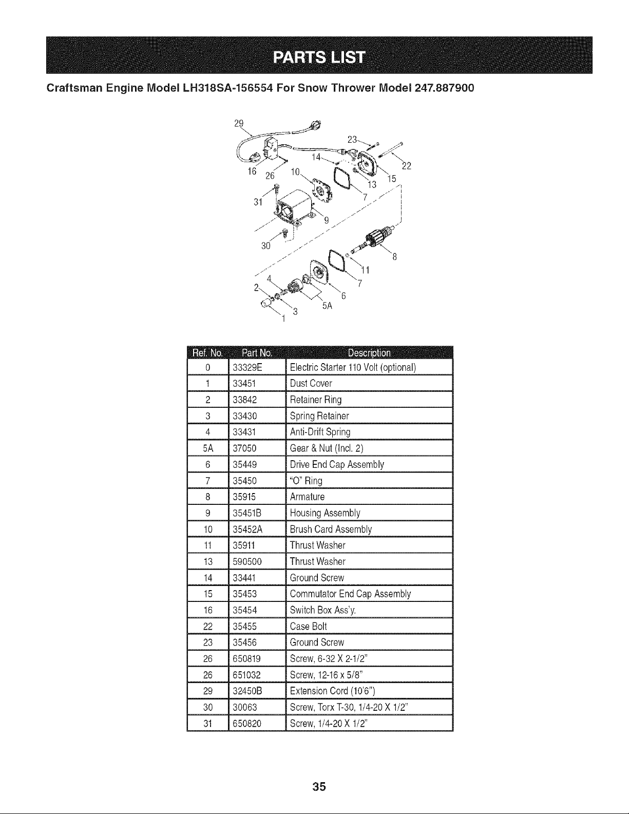
Craftsman Engine Model LH318SA-156554 For Snow Thrower Model 247.887900
29
16
22
33329E
1 33451
2 33842
3 33430
4 33431
5A 37050
6 35449
7 35450
8 35915
9 35451B
10 35452A
11 35911
13 590500
14 33441
15 35453
16 35454
22 35455
23 35456
26 650819
26 651032
29 32450B
30 30063
31 650820
D _ II m
ElectricStarter110Volt (optional)
DustCover
RetainerRing
SpringRetainer
Anti-DriftSpring
Gear&Nut (Incl•2)
DriveEndCap Assembly
"0" Ring
Armature
HousingAssembly
BrushCardAssembly
ThrustWasher
ThrustWasher
GroundScrew
CommutatorEndCap Assembly
SwitchBoxAss'y.
CaseBolt
GroundScrew
Screw,6-32 X 2-1/2"
Screw,12-16x 5/8"
ExtensionCord(10'6")
Screw,TorxT-30, 1/4-20X 1/2"
Screw,1/4-20X 1/2"
35
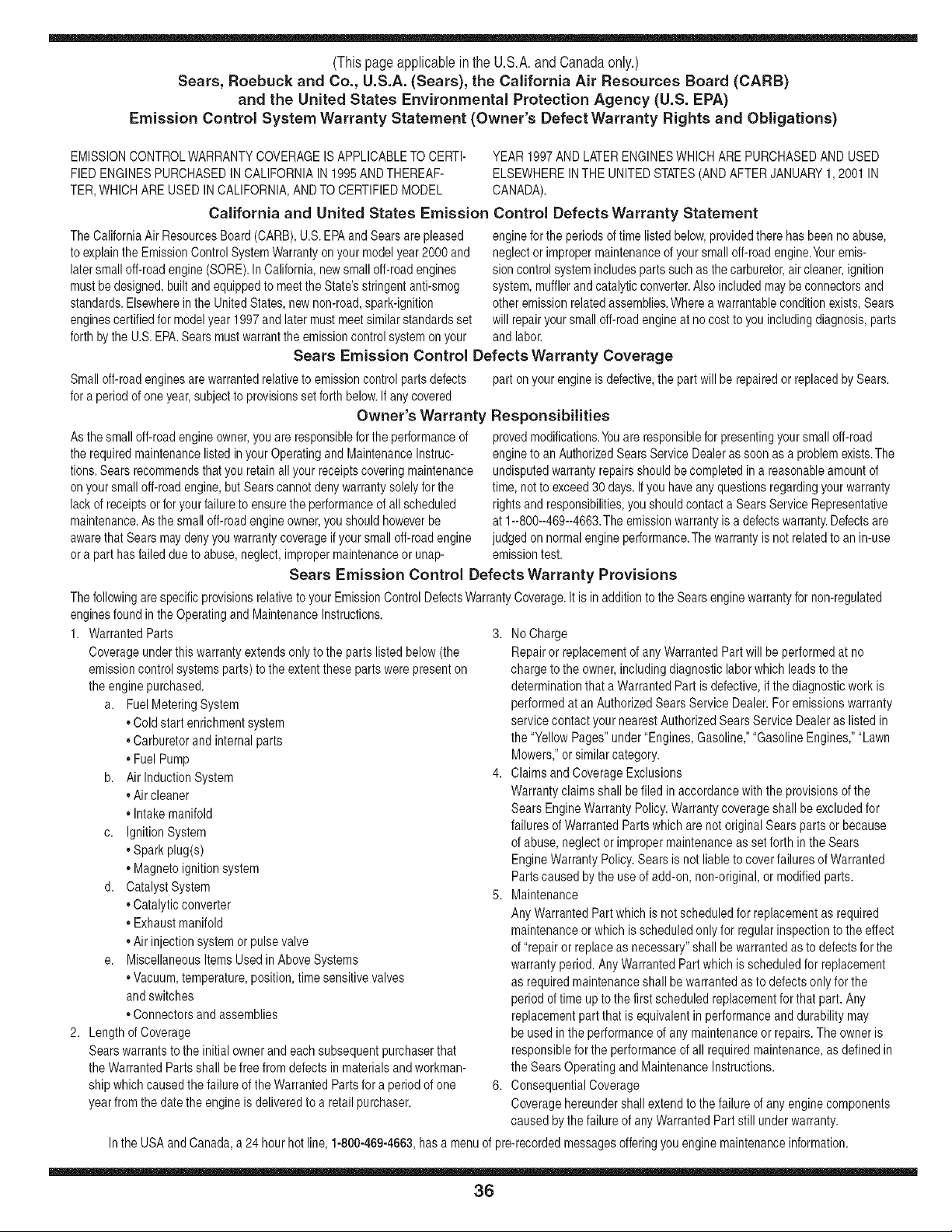
(Thispageapplicablein the U.S.A.and Canadaonly.)
Sears, Roebuck and Co., U.S.A. (Sears), the California Air Resources Board (CARB)
and the United States Environmental Protection Agency (U.S. EPA)
Emission ControJ System Warranty Statement (Owner's Defect Warranty Rights and ObJigations)
EMISSIONCONTROLWARRANTYCOVERAGEISAPPLICABLETOCERTI- YEAR 1997AND LATERENGINESWHICHARE PURCHASEDAND USED
FlED ENGINESPURCHASEDIN CALIFORNIAIN 1995ANDTHEREAF- ELSEWHEREINTHE UNITEDSTATES(ANDAFTERJANUARY1,2001 IN
TER,WHICHARE USED IN CALIFORNIA,ANDTO CERTIFIEDMODEL CANADA).
California and United States Emission Control Defects Warranty Statement
The CaliforniaAir ResourcesBoard(CARB),U.S.EPAandSearsare pleased
to explainthe EmissionControlSystemWarrantyon your modelyear2000 and
latersmalloff-roadengine(SORE).In California,newsmall off-roadengines
mustbe designed,builtand equippedto meettheState'sstringentanti-smog
standards.Elsewhereinthe UnitedStates, newnon-road,spark-ignition
enginescertifiedfor modelyear 1997and latermustmeetsimilarstandardsset
forth bythe U.S.EPA.Sears mustwarranttheemissioncontrol systemon your
enginefor the periodsof timelistedbelow,providedthere has beenno abuse,
neglector impropermaintenanceof your smalloff-roadengine.Youremis-
sion controlsystemincludespartssuch as thecarburetor,air cleaner,ignition
system,mufflerand catalyticconverter.Also includedmaybe connectorsand
otheremissionrelatedassemblies.Wherea warrantableconditionexists,Sears
will repairyour smalloff-roadengine at no cost to you includingdiagnosis,parts
and labor.
Sears Emission Control Defects Warranty Coverage
Smalloff-roadenginesarewarrantedrelativeto emissioncontrolpartsdefects
fora periodof oneyear,subjectto provisionsset forth below,Ifany covered
Owner's Warranty
Asthe smalloff-roadengineowner,you are responsiblefor the performanceof
therequiredmaintenancelistedinyour Operatingand MaintenanceInstruc-
tions.Sears recommendsthatyouretainallyour receiptscoveringmaintenance
on yoursmall off-roadengine,butSearscannotdenywarrantysolelyforthe
lackof receiptsor for yourfailureto ensurethe performanceof all scheduled
maintenance.Asthe smalloff-roadengineowner,you shouldhoweverbe
awarethat Sears maydenyyou warrantycoverageif your smalloff-roadengine
ora part hasfailed dueto abuse,neglect,impropermaintenanceor unap-
part onyour engineis defective,the part willbe repairedor replacedbySears.
Responsibilities
provedmodifications.Youare responsiblefor presentingyour smalloff-road
engineto an AuthorizedSearsService Dealeras soonas a problemexists.The
undisputedwarrantyrepairsshouldbe completedina reasonableamountof
time,not to exceed30 days.Ifyou haveanyquestionsregardingyour warranty
rightsand responsibilities,you shouldcontacta SearsServiceRepresentative
at 1--800--469--4663.Theemissionwarrantyis a defectswarranty.Defectsare
judgedon normalengineperformance.Thewarrantyis notrelatedto an in-use
emissiontest.
Sears Emission Control Defects Warranty Provisions
ThefollowingarespecificprovisionsrelativetoyourEmissionControlDefectsWarrantyCoverage.It isin additionto theSearsenginewarrantyfornon-regulated
enginesfound in the OperatingandMaintenanceInstructions.
1. WarrantedParts
Coverageunderthis warrantyextendsonly to the parts listed below(the
emissioncontrol systemsparts)to the extentthese parts werepresenton
theenginepurchased.
a. FuelMetering System
,,Coldstart enrichmentsystem
,,Carburetorand internal parts
• FuelPump
b. Airlnduction System
,,Air cleaner
• Intakemanifold
c. IgnitionSystem
,,Sparkplug(s)
• Magnetoignitionsystem
d. CatalystSystem
,,Catalyticconverter
• Exhaustmanifold
,,Air injectionsystemor pulsevalve
e. MiscellaneousItemsUsed inAboveSystems
• Vacuum,temperature,position,time sensitivevalves
andswitches
• Connectorsand assemblies
2. Lengthof Coverage
Searswarrantsto the initialownerand eachsubsequentpurchaserthat
theWarrantedParts shall befree from defectsin materialsandworkman-
ship whichcausedthe failureof the WarrantedPartsfor a periodof one
yearfrom the datethe engineis deliveredto a retailpurchaser.
3. No Charge
Repairor replacementof any WarrantedPartwill beperformedat no
chargeto the owner,includingdiagnosticlabor whichleadsto the
determinationthata WarrantedPartis defective,ifthe diagnosticwork is
performedat an AuthorizedSears ServiceDealer.For emissionswarranty
servicecontact your nearestAuthorizedSears ServiceDealeras listed in
the "YellowPages"under"Engines,Gasoline,""GasolineEngines,""Lawn
Mowers,"or similarcategory.
4. Claimsand CoverageExclusions
Warrantyclaimsshall be filed in accordancewiththe provisionsofthe
Sears EngineWarrantyPolicy.Warrantycoverageshall be excludedfor
failures of WarrantedPartswhichare not originalSears parts or because
of abuse, neglector impropermaintenanceas setforth in the Sears
EngineWarrantyPolicy.Searsis not liable to coverfailuresof Warranted
Partscausedby the useof add-on,non-original,or modified parts.
5. Maintenance
Any WarrantedPartwhich is not scheduledfor replacementas required
maintenanceor which is scheduledonly for regularinspectionto the effect
of "repairor replaceas necessary"shall be warrantedas to defectsfor the
warrantyperiod.Any WarrantedPartwhich is scheduledfor replacement
as requiredmaintenanceshallbe warrantedasto defectsonly for the
periodof time upto the first scheduledreplacementforthat part. Any
replacementpart that is equivalentin performanceand durabilitymay
be usedin the performanceof any maintenanceor repairs.The owneris
responsibleforthe performanceof all requiredmaintenance,as definedin
the SearsOperatingandMaintenanceInstructions.
6. ConsequentialCoverage
Coveragehereundershallextend to the failure of any engine components
caused bythefailure of anyWarrantedPartstill underwarranty.
Inthe USAand Canada,a 24 hour hot line, 1-800-469-4663,has a menuof pre-recordedmessagesofferingyou engine maintenanceinformation.
36
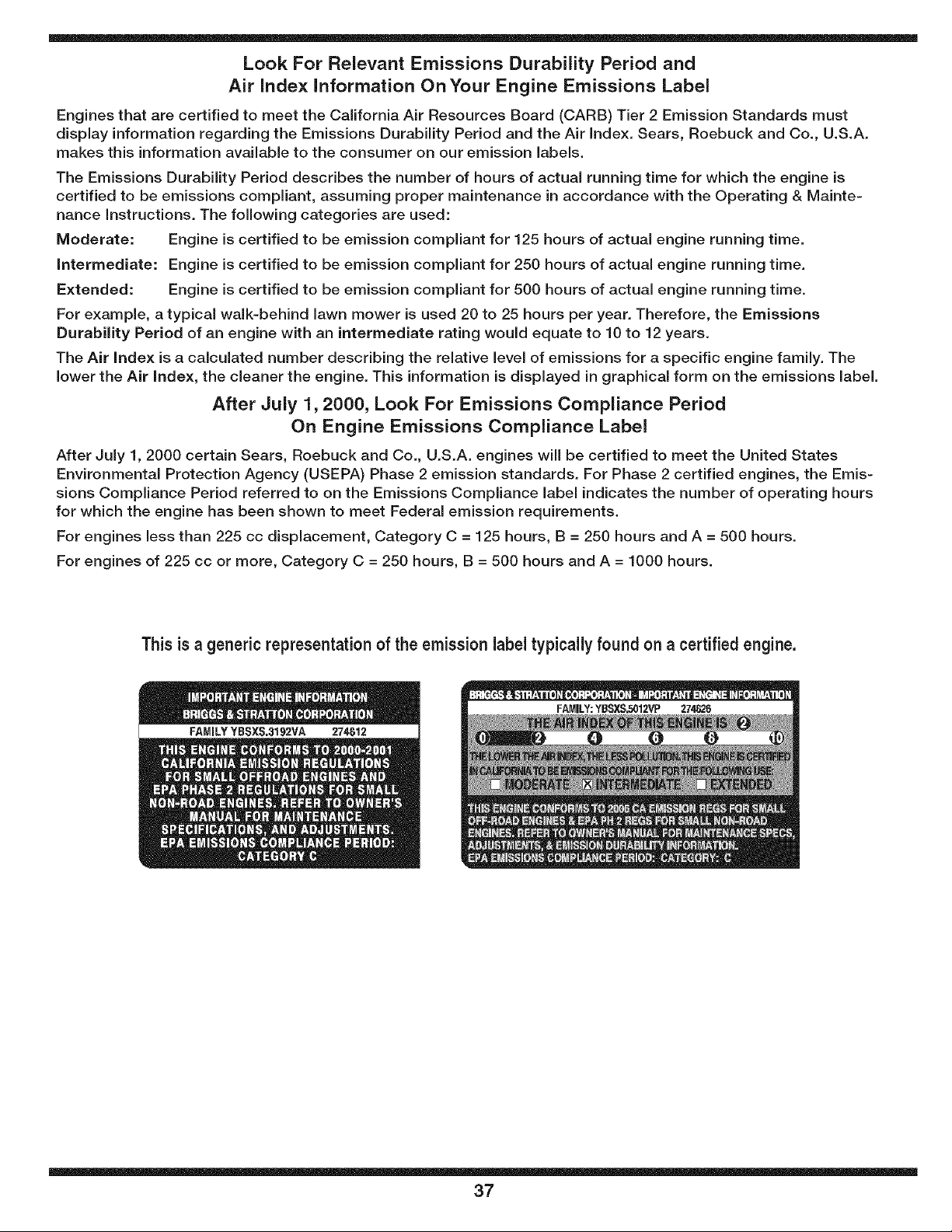
Look For Relevant Emissions Durability Period and
Air index information On Your Engine Emissions Label
Engines that are certified to meet the California Air Resources Board (CARB) Tier 2 Emission Standards must
display information regarding the Emissions Durability Period and the Air Index. Sears, Roebuck and Co., U.S.A.
makes this information available to the consumer on our emission labels.
The Emissions Durability Period describes the number of hours of actual running time for which the engine is
certified to be emissions compliant, assuming proper maintenance in accordance with the Operating & Mainte-
nance instructions. The following categories are used:
Moderate: Engine is certified to be emission compliant for 125 hours of actual engine running time.
intermediate: Engine is certified to be emission compliant for 250 hours of actual engine running time.
Extended: Engine is certified to be emission compliant for 500 hours of actual engine running time.
For example, a typical walk-behind lawn mower is used 20 to 25 hours per year. Therefore, the Emissions
Durability Period of an engine with an intermediate rating would equate to 10 to 12 years.
The Air index is a calculated number describing the relative level of emissions for a specific engine family. The
lower the Air index, the cleaner the engine. This information is displayed in graphical form on the emissions label.
After July 1,2000, Look For Emissions Compliance Period
On Engine Emissions Compliance Label
After July 1, 2000 certain Sears, Roebuck and Co., U.S.A. engines will be certified to meet the United States
Environmental Protection Agency (USEPA) Phase 2 emission standards. For Phase 2 certified engines, the Emis-
sions Compliance Period referred to on the Emissions Compliance label indicates the number of operating hours
for which the engine has been shown to meet Federal emission requirements.
For engines less than 225 cc displacement, Category C = 125 hours, B = 250 hours and A = 500 hours.
For engines of 225 cc or more, Category C = 250 hours, B = 500 hours and A = 1000 hours.
This is a generic representationof the emission labeltypically found on a certified engine.
37
Declaraci6n de garantfa ............................ PAgina 38
Acuerdo de protecci6n para reparaciones ... PAgina 39
PrActicas operaci6n seguras ..................... PAgina 40
Montaje ...................................................... PAgina 42
Operaci6n .................................................. PAgina 46
Servicio y Mantenimiento .......................... PAgina50
Almacenamiento fuera de temporada ....... PAgina 57
Soluci6n de problemas ............................. PAgina 58
Etiquetas de seguridad .............................. PAgina 7
Lista de piezas ........................................... PAgina 24
NOmero de servicio Cubierta posterior
Garantia de dos a_os para la maquina quitanieve Craftsman
Esteequipoest,.cubiertoporunagaranfiade dosahos,siempreque se mantenga,lubriquey ajustede acuerdocon las instruccionesdel
presentemanualdel operador.Duranteelahode garanfia,si este equiposufrecualquierfalla producidapordefectosen materialeso manode
obra,DEVUELVALOA SUCENTRODE PARTES& REPARACIONSEARSM_,SCERCANO,y SearsIo reparar_tsin ningOncargo.El serviciode
garanfiaa domicilioesterdisponibleperose aplicar_tun cargode traslado.
Esta garantia no cubre:
• Elementosdesechablesque se desgastanpor el usonormal,incluyendoentreotros,zapatasantideslizantes,placade raspadoy bujias.
Reparacionesnecesariasdebidoa negligenciadel operador,incluyendoentreotros,dahosmec_micoy electricoocasionadoporunalmace-
namientonoapropiado,abolladuracigOehal,falla porel usode aceitedegradoy/o cantidadno apropiadao fallapor no dar mantenimiento
al equipodeacuerdocon las instruccionescontenidasen el manualdel operador.
Limpiezao reparacionesal motor(sistemadecombustible)provocadaspor un combustiblecontaminadouoxidado(viejo). Engeneral,el
combustibledebeutilizarseen un periodono mayorde 30 diasa partir desu adquisici6n.
Equiposutilizadosparafinescomercialeso dealquiler.
Estagaranfias61otendr_,validezdurante90 dias si este productose utilizaen cualquiermomentoparafines comercialeso de alquiler.
Estagaranfias61otendravalidezmientrasel productose utiliceen los EstadosUnidos.
Estagaranfiale otorgaderechoslegalesespecificos,peroustedpodriagozarde otros derechosen raz6nde su lugarde residencia.
Sears, Roebuck and Co., Hoffman Estates, IL 60179
Tipo de aceite del motor:
Capacidadde aceitedel motor:
Capacidadde combustible:
Bujias:
Separaci6nde lasbujias:
SAE5W-30
26 onzas
4 cuartos
Champion®RJ19LM
.030"
N_merode modelo ..........................................................
Numerode serie ..............................................................
Fechade compra .............................................................
Registrearribael nOmerodel modelo,el nOmerode seriey la fecha
de compra
© Sears Brands,LLC
38
Felicitacionespor haberrealizadounaadquisici6ninteligente.El
productoCraftsman@que haadquiridoest,.disehadoy fabricado
parabrindarmuchosahosde funcionamientoconfiable.Perocomo
todoslosproductosa vecespuederequerirde reparaciones.Esen
ese momentocuandoel disponerde unAcuerdode protecci6npara
reparacionesle puedeahorrardineroy problemas.
Acontinuaci6nse detallanlos puntosincluidosen el Acuerdo:
, Servicio experto prestadopor nuestros12,000especialistasen
reparacionesprofesionales
Servicio ilimitadosin cargo para las piezasy la manode obra en
todaslas reparacionescubiertas
• Reemplazodel productosi noes posiblerepararel producto
cubierto
Descuentode 10%del precionormaldelservicioy delas piezas
relacionadascon el mismoquenoestencubiertaspor el acuerdo;
adem_ts,10%delprecionormalde laverificaci6nde manten-
imientopreventivo
, Ayudar_pida portel_fono- asistenciatelef6nicaa cargode un
tecnicode Searsparalos productosquerequierenreparaci6n
a domicilio,adem_tsdeunaprogramaci6nconvenientepara la
reparaci6n
Unavez adquiridoel Acuerdo,puede programarelserviciocon
tan s61orealizaruna Ilamadatelef6nica.Puede Ilamaren cualquier
momentodel dia o de la nocheo programarunservicioen linea.
Searsdisponede m_.sde 12.000especialistasenreparaciones
profesionalesque tienenaccesoa m_tsde 4.5 millonesdepiezasy
accesoriosde buenacalidad.Estees el tipo deprofesionalismoen
el quepuedeconfiarparaque leayudea prolongarla vida 0til del
productorecientementeadquiridoen losahos por venir,iAdquierahoy
su acuerdode protecci6nparareparaciones!
Se aplican determinadaslimitacionesy exclusiones.Paraobtener
informaci6nadicional y preciosIlameal 1-800-827-6655.
Serviciode instalaci6nde Sears
Sideseasolicitarla instalaci6nprofesionalde Searsde aparatos
dom_sticos,dispositivospara abrir portones,calentadoresde agua y
otrosarticulosdom_sticosimportantes,en losEstadosUnidosIlame
al 1-800-4-MY-HOME@.
39
La presenciade estesimbolo indicaque setrata de
instruccionesimportantesde seguridadquese deben
respetarpara evitar poneren peligro su seguridad
personaly/o materialy lade otraspersonas.Leay siga
todas las instruccionesde estemanualantesde poner
en funcionamientoesta maquina.Si norespetaestasinstruccionespodria
provocarlesionespersonales.Cuandovea estesfmbolo,i presteatenciona
la advertencia!
Su responsabilidad: Restrinjael usode esta m_tquinamotorizada
alas personasquelean,comprendany respetenlas advertenciase
instruccionesque aparecenen estemanualyen la m_tquina.
Esta maquinafue construidaparaser operadade acuerdocon las reglas
de seguridadcontenidasen este manual.AI igual quecon cualquiertipo
de equipo motorizado,un descuidoo error por partedel operadorpuede
producirlesionesgraves.Estamaquinaes capazde amputarmanosy pies
y dearrojarobjetoscon gran fuerza. Denorespetarlas instruccionesde
seguridadsiguientesse puedenproducirlesionesgraveso la muerte.
Elescape del motorde este producto,algunosde suscomponentesy
algunoscomponentesdel vehfculocontieneno liberan sustanciasqdmicas
que elestadodeCaliforniaconsideraquepuedenproducir cancer,defectos
de nacimientou otros problemasreproductivos.
CAPACITACIAN
,, Lea,entienday cumplatodas las instruccionesincluidasen la maquina
yen los manualesantesde montarlay utilizarla.Guardeeste manual
en un lugarseguropara consultasfuturasy regulares,asf como para
solicitarrepuestos.
,, Familiarfcesecon todos los controlesy sufuncionamientoapropiado.
Sepacome detenerla maquinay come desengranarlos controles
r@idamente.
,, No permitanuncaque losnihosmenoresde 14 ahosutilicen esta
maquina.Los ni_os de 14ahosy masmayoresdeben leery com-
prenderlas instruccionesde funcionamientoy las reglasde seguridad
contenidasen estemanual,y tambiendeben sercapacitadosy estar
supervisadospor unode los padres.
,, Nunca permitaquelos adultosutilicen estamaquinasin recibirantes la
instruccionapropiada.
,, Los objetosarrojadospor lamaquinapuedenproducirlesionesgraves.
Planifiqueel patronen el queva air arrojandonievepara evitar quela
descargade materialse realicehacia los caminos,los observadores,
etc.
,, Mantengaa los observadores,ayudantes,mascotasy ni_os perIo
menosa 75 piesde la maquinamientrasla mismaesta enfunciona-
miento.Detengala maquinasi alguienentraen lazona.
,, Sea precavidopara evitarpatinarseo caerse especialmentecuando
operala maquinaen reversa.
PREPARATIVOS
,, InspeccioneminuciosamenteelAreadondeutilizaraelequipo.Saque
todoslosfelpudos,periAdicos,trineos,tablas,cablesy otrosobjetos
extraSoscon los quepodriatropezaro quepodrianser arrojadospor la
barrena/ motor.
,, Paraprotegerselos ojosutilice siempreanteojoso antiparrasde
seguridadmientrasopera la maquinao mientrasla ajustao repara.Los
objetos arrojadosque rebotanpuedenlesionargravementelavista.
,, Nooperela maquinasinla vestimentaadecuadapara estaral aire libre
en invierno.No utilicealhajas,bufandaslargasu otras prendassueltas
que podrianenredarseen laspartesmAviles.Utiliceun calzado especial
parasuperficiesresbaladizas.
,, Useun prolongadory un tomacorrientede tres cablescon conexiAna
tierra paratodas las unidadescon motores de encendidoelectrico.
,, Ajuste la altura de la caja del tomacorrientepara limpiarla gravao las
superficiesconpiedrastrituradas.
,, Desengranetodas laspalancasde controlantes de arrancarel motor.
,, Nuncaintenterealizarajustesmientrasel motorestaen marchaexcepto
en loscasos espedficamenterecomendadosen el manualdel operador.
,, Dejequeel motory la maquinaseadapten a latemperaturaexterior
antes de comenzara sacar lanieve.
,, ParaevitarlesionsepersonalesodaSosmaterialesseasumamentecuidadosoal
manipularlagasdina.Lagaselinaesaltamenteinflamableysusvaporespuedencausar
explosiones.SepuedelesionargravemsetesJderramagasdinasebreustedosebrela
ropayaquesepuedeprenderfuego.Laveselapiely camloiesederopadeinmediato.
,, Utilicesale recipientespara gasolinaautorizados.
,, Apaguetodosloscigarrillos,cigarros,pipasy otrasfuentesde combustion.
,, Nuncacarguecombustibleen la maquinaen un espaciocerrado.
,, Nuncasaque latapa del gas niagreguecombustiblemientrasel motor
estacaliente o en marcha.
,, Dejequeel motorse enfrie por Io menosdos minutosantesde volvera
cargar combustible.
,, Nuncarecargueel tanque de combustible.Lleneel tanqueno masde
1/2pulgadaper debajode la basedel cuello del filtroparadejar espacio
para ladilataciondel combustible.
,, Vuelvaa colocar la tapa de lagasolinay ajustelabien.
,, Limpielagasolinaderramadasobre el motory el equipo.Trasladela
maquinaa otra zona. Espere5 minutos antesde encenderel motor.
,, Nuncaalmacenela maquinao el recipientede combustibleen un
espaciocerrado dondehayafuego,chispaso luz piloto (porejemplo,
hornos,calentadoresde agua,calefactores,secadoresde ropa,etc.).
,, Dejequela maquinase enfrie por Io menos5 minutosantes de
guardarla.
40
OPERACION
• No pongalas maneso los piescerca de las piezas rotatorias,en la caja
de labarrena/ motoro en el montajedel canalde descarga.Elcontacto
con las piezasrotatoriaspuedeproducirla amputaciondemanosy pies.
,, La palancade control de la barrena/ motores un dispositivode seguri-
dad. Nuncapase poralto su funcionamiento.De hacerlola operaci6nde
la maquinaes riesgosay puedeocasionarlesiones.
,, Laspalancasde controldebenfuncionarbienen ambasdireccionesy
regresarautomaticamentea laposicionde desengranecuandose las
suelta.
,, Nuncaoperelamaquinasifaltaunmontajedelcanalo sielmismoesta.dafiado.
Mantengatodoslosdispositivosdeseguridadensulugaryen funcionamiento.
,, Nunca enciendaun motoren espacioscerradoso en unazonacon poca
ventilacion.Elescapedel motorcontienemonoxidode carbono,un gas
inodoroy letal.
,, No utilicela maquinabajo la influenciadel alcoholo las drogas.
,, El silenciadory el motorse calientany puedenproducir quemaduras.No
lostoque.
,, Sea sumamenteprecavidocuandooperela maquinasobre una
superficiecon gravao cuandola cruce. Mantengasealerta por si se
presentanpeligros ocultoso transito.
,, Tengacuidado cuandocambiede direcciono cuandooperela maquina
en pendientes.
,, Planifiqueel patronen el queva air arrojandonieve paraevitar que
la descargade materialse produzcahacia lasventanas,las paredes,
losautomoviles,etc.y evitar asi posiblesdaflosmaterialeso lesiones
producidaspor los rebotes.
,, Nunca dirija la descarga hacia losniflos, los observadoresy las
mascotasni deje que nadiese pare delantede la maquina.
,, No sobrecarguela capacidadde la maquinatratandode sacar la nieve
muyra.pidamente.
,, Nunca opereesta maquinasin buenavisibilidado iluminaci6n.Siempre
debe estarsegurode queesta bienafirmadoy sostengabienlas
manijas.Camine,nuncacorra.
,, Corte lacorrientea la barrena/ motorcuandotransportela maquinao
cuandola mismano estaenuso.
,, Nunca operela maquinaa alta velocidadde desplazamientosobre
superficiesresbaladizas.Mirehacia abajoy haciaatras y tenga cuidado
cuandovayamarchaatra.s.
,, Si la maquinacomenzaraa vibrar de maneraanormal,detengael motor,
desconecteel cablede la bujfay pongalade maneraque hagamasa
contrael motor.Inspeccionela maquinaminuciosamentepara ver si
estadaflada. Reparetodos losdaflos antesde encendery operar la
maquina.
,, Desengranetodas las palancasde control y detengael motorantesde
dejar la posicionde operacion(detrasde lasmanijas).Esperea que la
barrena/ motorse detengapor completeantes de destaparel montaje
del canalo realizarajustese inspecciones.
,, Nunca pongalasmanos en las aberturasde descargao de recoleccion.
Utilice siemprela herramientade limpiezaque se adjuntaparadestapar
la aberturade descarga. Nodestapeel montajedelcanal mientrasel
motorestaen funcionamiento.Antes de destaparlo,apagueel motory
permanezcadetrasdelas manijashastaquetodas laspartesmovilesse
hayandetenido.
,, Use solo unionesy accesoriosaprobadosper el fabricante(perejemplo,
pesaspara las ruedas,cadenasparalos neumaticos,cannas, etc.).
,, Si se presentansituacionesque no esta.nprevistasen este manual,sea
cuidadosoy use el sentidocomun.Contacteconsu centrode servicio
Sears paraobtener ayuda.
MANTENIMIENTO Y ALMACENAMIENTO
,, Nuncamanipulelosdispositivosde seguridadde maneraimprudente.
Controleperi6dicamenteque funcionende formaadecuada.Remftasea
las seccionesde mantenimientoy ajustede este manual.
,, Antesde realizarlalimpieza,repararo revisarla maquina,desengrane
todas las palancasde controly detenga elmotor.Esperea que la bar-
rena/ motorse detengaporcomplete.Desconecteelcable dela bujia
y pongalode manera quehaga masacontrael motorparaevitar quese
enciendade maneraaccidental.
,, Controlefrecuentementequetodos lospernosy tornillosesten bien
ajustadosparacomprobarque la maquinase encuentraen condiciones
segurasde funcionamiento.Asimismo,realiceuna inspecci6nvisual de
la maquinaparacontrolarsi la mismaesta daflada.
,, Nocambiela configuraci6ndel reguladordel motorni acelere de-
masiadoel mismo.El reguladorcontrolala velocidadmaximasegurade
operaciondel motor.
,, Lasplacasde raspadoy laszapatasantideslizantesqueseusanconlamaquina
quitanievesedesgastany sedafian.Paraprotegersuseguridad,verifique
frecuentementetodosloscomponentesy reemplacelossoloconpartesdelos
fabricantesdeequiposoriginales(OEM)."Lautilizaci6ndepiezasquenocum-
planconlasespecificacionesdeequiposoriginalespodrfatenercomeresultado
un rendimientoincorrecto,y ademaslaseguridadpodrfaestarcomprometida"
,, Reviselos controlesperiodicamentepara verificarque engraneny
desengranenadecuadamentey ajustelossi es necesario.Consultela
seccionde ajustesen este manualdel operadorpara obtenerinstruc-
ciones.
,, Mantengao reemplacelas etiquetasde seguridade instruccionessegt]n
sea necesario.
,, Respetelas normasreferentesa la disposicioncorrectay las reglamen-
tacionessobre gas, combustible,etc. paraprotegerel medioambiente.
,, Antesde almacenarla maquinaenciendalaunos minutespara sacarla
nieveque hayaquedadoen la mismay paraevitarasi que se congelela
barrena/ motor.
,, Nuncaalmacenela maquinao el recipientede combustibleen un
espaciocerrado dondehayafuego,chispaso luz pilotocomo por
ejemplo,calentadoresde agua, hornos,secadoresde ropa,etc.
,, Consultesiempreel manualde funcionamientopara conocerlasinstruc-
cionesadecuadaspara el almacenamientofuera de temporada.
No modifique el motor
Paraevitarlesionesgraveso la muerte,no modifiqueelmotorbajo ninguna
circunstancia.Si cambialaconfiguraci6ndel reguladorel motorpuededescon-
trolarsey operara velocidadesinseguras.Nuncacambielaconfiguracionde
fabricadel reguladordel motor.
41
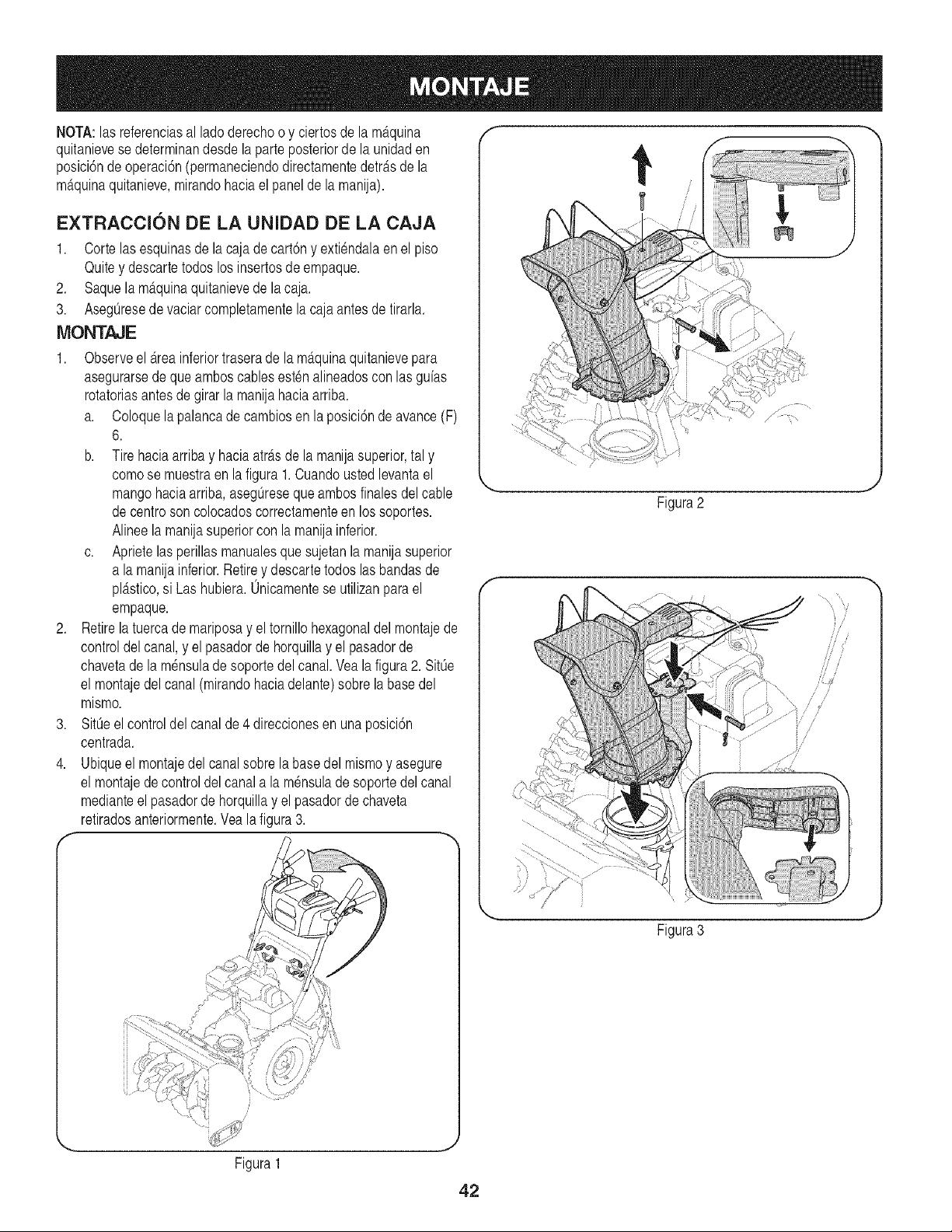
NOTA:las referenciasal ladoderechoo y ciertosde la m_tquina
quitanievesedeterminandesdela parteposteriorde la unidaden
posici6ndeoperaci6n(permaneciendodirectamentedetras de la
m_tquinaquitanieve,mirandohaciael panelde la manija).
EXTRACCI6N DE LA UNIDAD DE LA CAJA
1. Cortelasesquinasde la caja decart6ny extiendalaenel piso
Quitey descartetodoslos insertosde empaque.
2. Saquela maquinaquitanievede la caja.
3. Aseg0resede vaciarcompletamentela cajaantes de tirarla.
MONTAJE
1. Observeel _.reainferiortraserade la m_tquinaquitanievepara
asegurarsede queamboscablesestenalineadosconlas guias
rotatoriasantesde girar la manijahaciaarriba.
a. Coloquela palancadecambiosen la posici6nde avance(F)
6.
b. Tirehaciaarriba y haciaatr_tsde lamanijasuperior,tal y
comose muestraen lafigura 1.Cuandoustedlevantael
mangohaciaarriba,asegOresequeambosfinalesdelcable
decentrosoncolocadoscorrectamenteen lossoportes.
Alineela manijasuperiorcon lamanijainferior.
c. Aprietelasperillasmanualesque sujetanla manijasuperior
a la manijainferior.Retirey descartetodoslasbandasde
pl_.stico,si Las hubiera.Onicamentese utilizanpara el
empaque.
2. Retirela tuercade mariposay el tornillohexagonaldel montajede
controldelcanal,y el pasadorde horquillay el pasadorde
chavetade la m_nsulade soportedel canal. Veala figura2. SitOe
el montajedelcanal (mirandohaciadelante)sobrela basedel
mismo.
3. SitOeel controldel canalde 4 direccionesen unaposici6n
centrada.
4. Ubiqueel montajedel canalsobrela basedel mismoy asegure
el montajedecontroldelcanala la m_nsulade soportedel canal
medianteel pasadorde horquillay el pasadorde chaveta
retiradosanteriormente.Veala figura3.
f
i
i /
Figura1
Figura2
iS i
/j
/
/
i/
Figura3
42
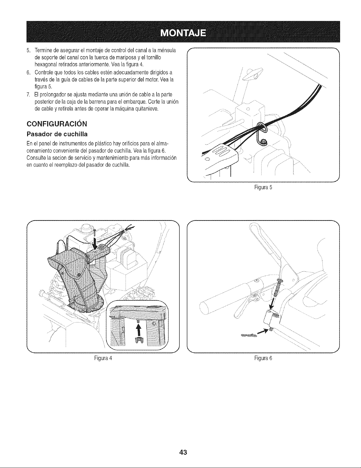
5. Terminede asegurarel montajede control del canala la mensula
desoportedelcanalcon la tuercade mariposay el tornillo
hexagonalretiradosanteriormente.Vea la figura4.
6. Controlequetodoslos cablesest_nadecuadamentedirigidosa
travesde la gufade cablesde la parte superiordel motor.Veala
figura5.
7. Elprolongadorseajustamedianteunauni6ndecablea la parte
posteriorde lacaja de la barrenaparael embarque.Corte la uni6n
decabley refirelaantesdeoperarla m£quinaquitanieve.
CONFIGURACI6N
Pasador de cuchilla
Enel panelde instrumentosde pl£sticohayorificiosparael alma-
cenamientoconvenientedel pasadorde cuchilla.Vea la figura6.
Consultela secion de servicioy mantenimientopara m£sinformaci6n
encuantoel reemplazodelpasadorde cuchilla.
! i
i i
i i
....................i i
Figura5
i
i
Figura4
/ si
, ....... / ,/
(
Figura6
43
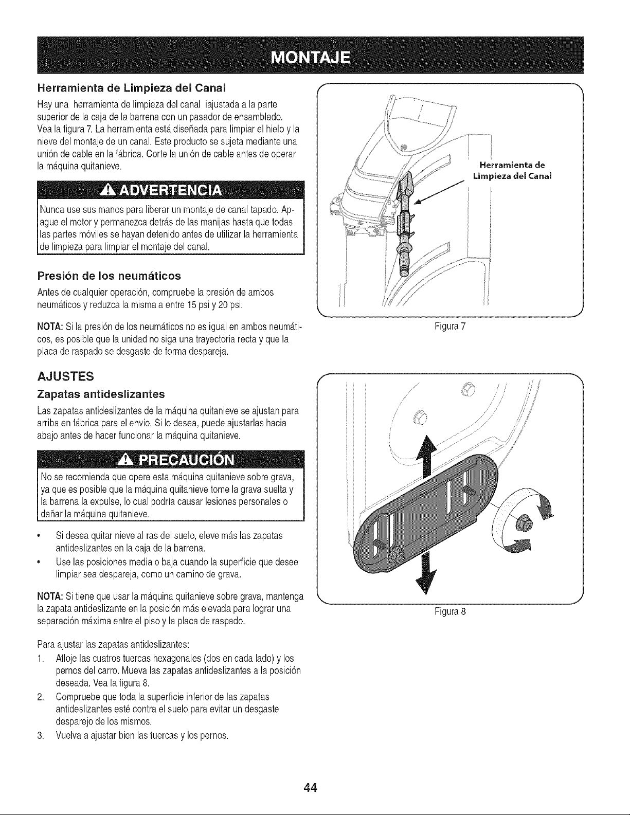
Herramienta de Limpieza del Canal
Hayuna herramientade limpiezadel canal iajustadaa la parte
superiorde la caja dela barrenacon unpasadorde ensamblado.
Veala figura7. La herramientaest,. disehadaparalimpiarel hielo y la
nievedel montajede un canal.Este productose sujetamedianteuna
uni6nde cableen la f_.brica.Corte la uni6n de cableantesde operar
la m_tquinaquitanieve.
Nuncausesus manospara liberar un montajede canaltapado.Ap-
agueel motory permanezcadetr_.sde las manijashastaquetodas
laspartes m6vilesse hayandetenidoantes de utilizar la herramienta
de limpiezaparalimpiarel montajedel canal.
Presion de los neumaticos
Antesde cualquieroperaci6n,compruebela presi6nde ambos
neum_tticosy reduzcala mismaa entre 15psiy 20psi.
NOTA:Si la presi6nde los neum_tticosno es igualen ambosneum_tti-
cos,es posibleque la unidadno siga unatrayectoriarectay quela
placade raspadose desgastede formadespareja.
Herrarnienta de
Limpieza clel Canal
Figura7
AJUSTES
Zapatas antideslizantes
Laszapatasantideslizantesde lam_.quinaquitanievese ajustanpara
arribaen f_.bricapara el envio. Si Iodesea,puedeajustarlashacia
abajoantesde hacerfuncionarla m_tquinaquitanieve.
Nose recomiendaque opereesta m_tquinaquitanievesobregrava,
ya que es posiblequela m_tquinaquitanievetomelagravasueltay
labarrenalaexpulse,Io cualpodriacausarlesionespersonaleso
daharla m_tquinaquitanieve.
,, Sideseaquitar nieveal rasdel suelo,elevem_tslaszapatas
antideslizantesen la cajade la barrena.
,, Uselas posicionesmediao bajacuandola superficieque desee
limpiarsea despareja,comouncaminodegrava.
NOTA:Si tieneque usarla m_.quinaquitanievesobregrava,mantenga
lazapataantideslizanteen la posici6nm_.selevadaparaIograruna
separaci6nmaximaentreel pisoy la placade raspado.
Paraajustarlaszapatasantideslizantes:
1. Aflojelas cuatrostuercashexagonales(dosen cada lado)y los
pernosdel carro.Muevalas zapatasantideslizantesa la posici6n
deseada.Vealafigura8.
2. Compruebeque todala superficieinferiorde laszapatas
antideslizanteseste contrael sueloparaevitar un desgaste
desparejode los mismos.
3. Vuelvaa ajustarbien las tuercasy lospernos.
/
/
J
//
//
/ //
Figura8
44
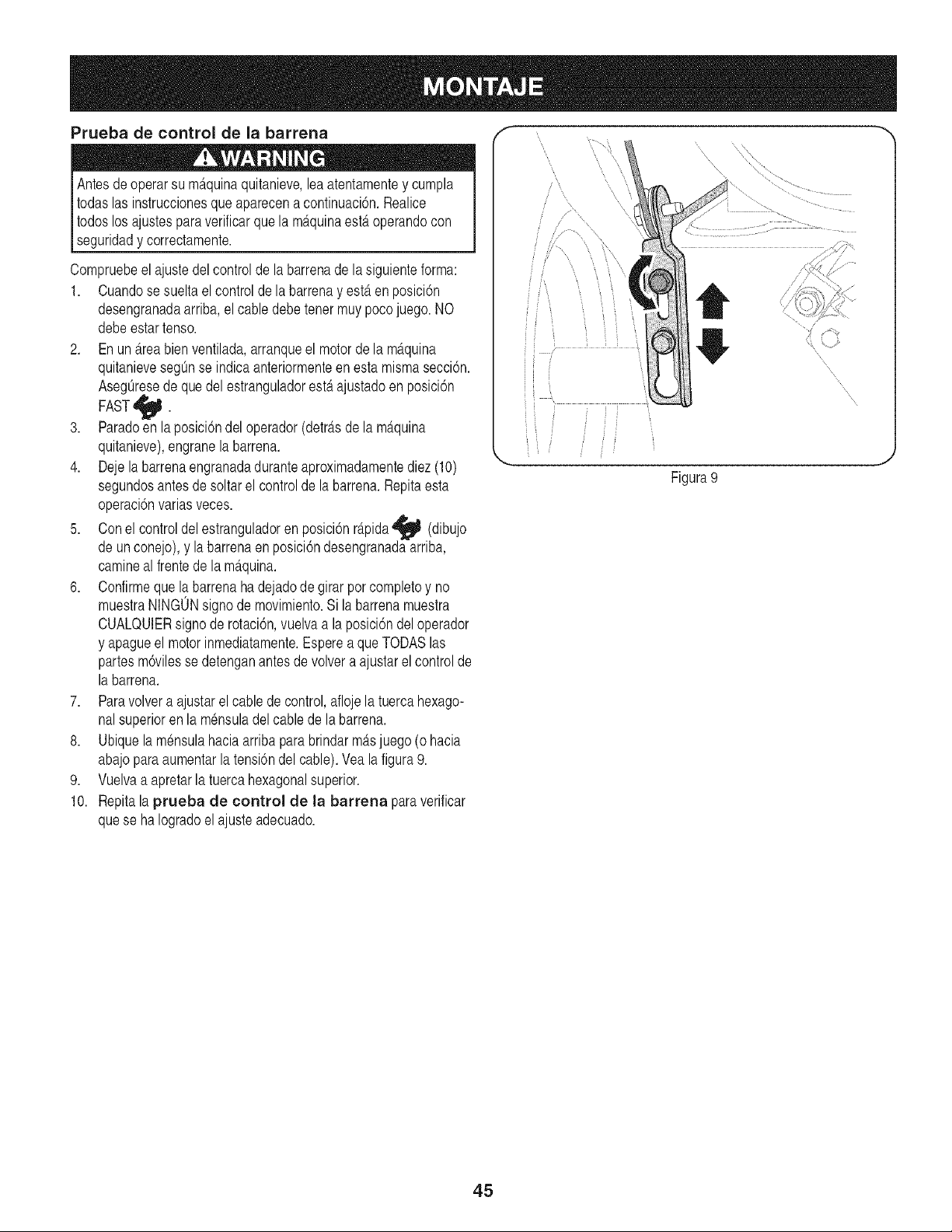
Prueba de control de la barrena
Antesde operarsu m_.quinaquitanieve,leaatentamentey cumpla
todaslas instruccionesqueaparecena continuaci6n.Realice
todoslosajustesparaverificarque la m_tquinaesteroperandocon
lsegur dady correctamente.
Compruebeelajustedel controlde labarrenadela siguienteforma:
1. Cuandose sueltael controlde la barrenay esteren posici6n
desengranadaarriba,el cable debetener muy pocojuego.NO
debeestartenso.
2. Enun_treabien ventilada,arranqueel motorde la m_.quina
quitanievesegOnse indicaanteriormenteen estamismasecci6n.
AsegOresedequedel estranguladoresterajustadoen posici6n
FAST_.
3. Paradoen la posicidndel operador(detrfisde la mfiquina
quitanieve),engranela barrena.
4. Dejela barrenaengranadaduranteaproximadamentediez(10)
segundosantesde soltarel controlde labarrena.Repitaesta
operaci6nvarias veces.
5. Conel controldel estranguladoren posici6nr_.pida_ (dibujo
de unconejo),y la barrenaen posici6ndesengranadaarriba,
camineal frentedela m_tquina.
6. Confirmeque la barrenaha dejadode girarporcompletoy no
muestraNINGONsignode movimiento.Si labarrenamuestra
CUALQUIERsigno derotaci6n,vuelvaa la posici6ndel operador
y apagueel motorinmediatamente.Esperea que TODASIns
partesm6vilesse detenganantesde volvera ajustarel control de
la barrena.
7. Paravolvera ajustarel cablede control,aflojela tuercahexago-
nalsuperioren la m6nsuladel cablede la barrena.
8. Ubiquela m6nsulahaciaarribapara brindarm_tsjuego(o hacia
abajoparaaumentarla tensi6ndelcable).Yealafigura9.
9. Vuelvaa apretarla tuercahexagonalsuperior.
10. Repitala prueba de control de la barrena para verificar
quese ha Iogradoel ajusteadecuado.
Figura9
45
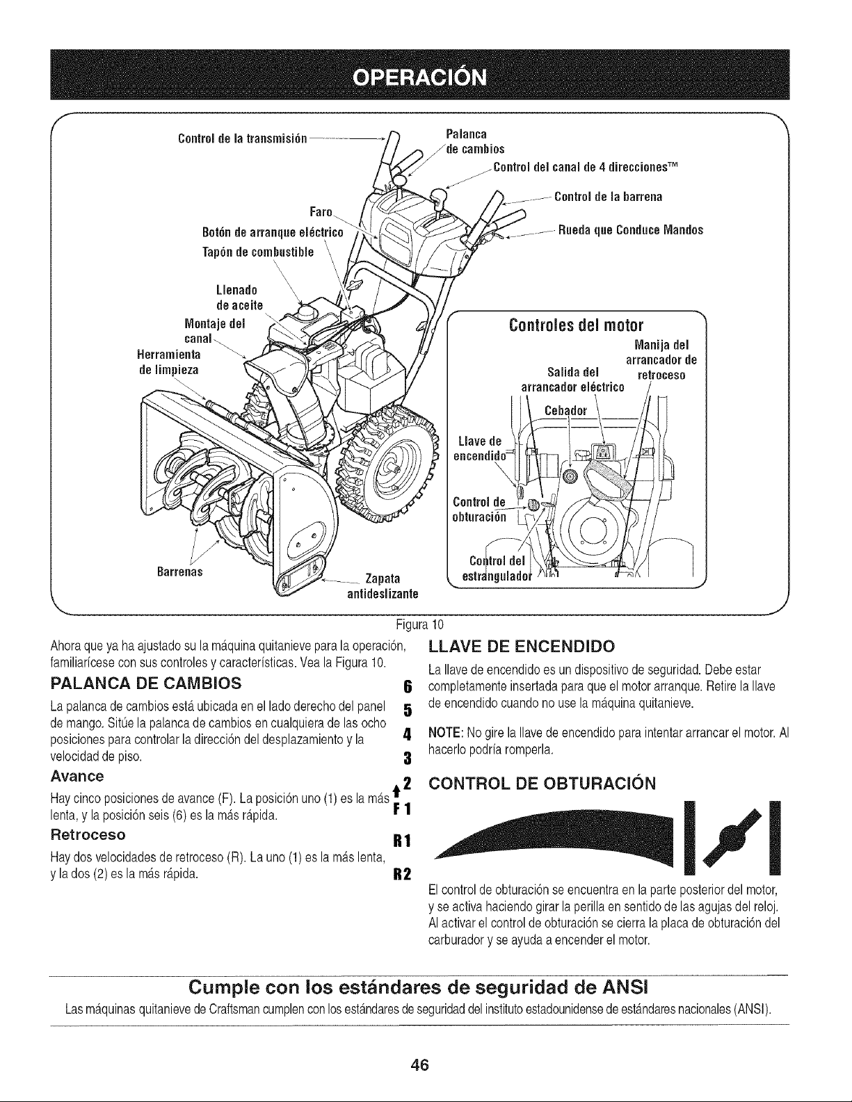
Controlde la transrnisi6n.....................
Faro _
Uenado A/,_ /
deaceite
IVlontajedel
Herramienta _, _ _Sf'_
delimpieza _.l _t
antideslizante
Palanca
f.j_de camhios
,_/_Control del canalde4 direccionesTM
/
_._ ......... Control de la barrena
1 _ __.......RgedaqgeConduceIVlandos
Controles ciel motor
IVlanijadel
arrancadorde
Saiidadel retroceso
arrancadoreldctrico
X Cebador
Liavede
Controlde
obturaci6n
Figura10
Ahoraqueya ha ajustadosu la m_tquinaquitanieveparala operaci6n,
familiaricesecon sus controlesy caracterfsticas.Veala Figura10.
PALANCA DE CAMBIOS 6
Lapalancade cambiosest,.ubicadaenel ladoderechodel panel 5
de mango.SitOela palancade cambiosen cualquierade lasocho
posicionesparacontrolarla direcci6ndel desplazamientoy la 4
velocidadde piso. a
Avarice
z
,&
Haycincoposicionesde avance(F). La posici6nuno (1) es la m_ts_ 4
lenta,y la posici6nseis (6)es lam_tsr_tpida.
r !
Retroceso
LLAVE DE ENCENDIDO
LaIlavedeencendidoes undispositivode seguridad.Debeestar
completamenteinsertadaparaque el motor arranque.Retirela Ilave
de encendidocuandono usela m_tquinaquitanieve.
NOTE:No girela Ilavedeencendidopara intentararrancarel motor.AI
hacerlopodrfaromperla.
Haydos velocidadesde retroeeso(R). Launo(1)es la m_tslenta,
y la dos (2)es lam_tsr_tpida.
CONTROL DE OBTURACION
,, I,,'l
B2
Elcontroldeobturaci6nse encuentraen la parteposteriordel motor,
y se activahaciendogirarlaperillaen sentidode lasagujasdel reloj.
AI activarel controlde obturaci6nse cierrala placa deobturaci6ndel
carburadory se ayudaa encenderel motor.
Cumpie con los est_ndares de seguridad de ANSI
Lasm_.quinasquitanievedeCraftsmancumplenconlosest_.ndaresde seguridaddel institutoestadounidensedeest_mdaresnacionales(ANSI).
46
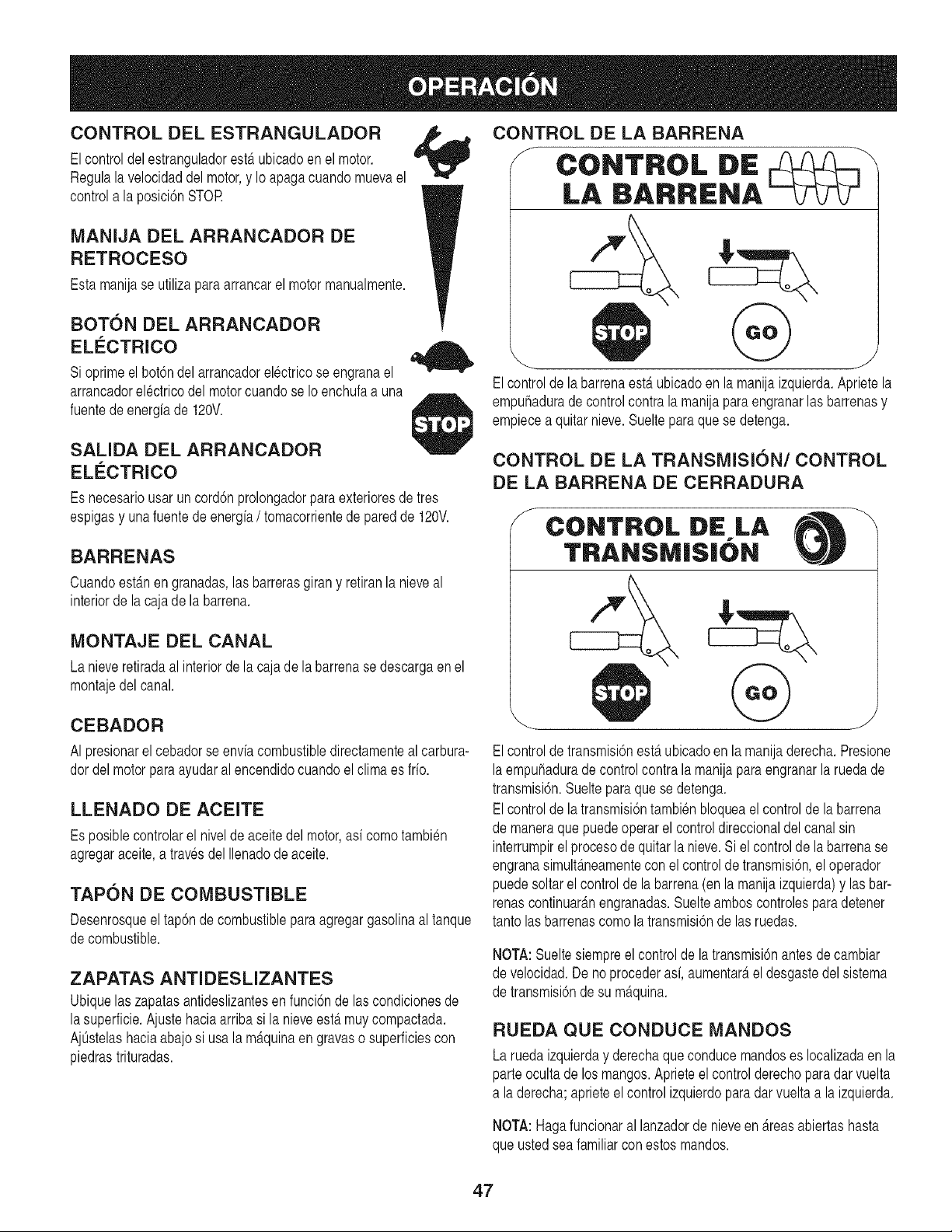
CONTROL DEL ESTRANGULADOR
Elcontroldelestranguladoresterubicadoen el motor.
Regulala velocidaddel motor,y Io apagacuandomuevael
controla la posici6nSTOR
MANIJA DEL ARRANCADOR DE
RETROCESO
Estamanijase utilizaparaarrancarel motormanualmente.
BOTON DEL ARRANCADOR
ELC:CTRICO
Si oprimeel bot6ndel arrancadorelectricose engranael
arrancadorelectricodel motorcuandose Ioenchufaa una
fuentedeenergiade 120V.
SALIDA DEL ARRANCADOR
ELC:CTRICO
Es necesariousar uncord6nprolongadorparaexterioresde tres
espigasy una fuentede energia/ tomacorrientede paredde 120V.
BARRENAS
Cuandoestgmengranadas,las barrerasgirany retiranla nieveal
interiorde la cajade la barrena.
MONTAJE DEL CANAL
La nieveretiradaal interiorde la cajade la barrenase descargaen el
montajedel canal.
CEBADOR
AI presionarel cebadorse enviacombustibledirectamenteal carbura-
dordel motorparaayudaral encendidocuandoelclimaes fifo.
LLENADO DE ACEITE
Es posiblecontrolarel nivelde aceite del motor,asi como tambien
agregaraceite,a travesdel Ilenadode aceite.
TAPON DE COMBUSTIBLE
Desenrosqueel tapSndecombustibleparaagregargasolinaal tanque
decombustible.
ZAPATAS ANTIDESLIZANTES
Ubiquelaszapatasantideslizantesen funcbn de lascondicionesde
lasuperficie.Ajustehaciaarriba si la nieveest,.muycompactada.
AjOstelashaciaabajosi usala m_tquinaen gravaso superficiescon
piedrastrituradas.
CONTROL DE LA BARRENA
J CONTROL DE
LA IBARRIENA
@
Elcontrolde labarrenaestAubicadoen la manijaizquierda.Aprietela
empuhadurade control contrala manijaparaengranarlas barrenasy
empiecea quitarnieve.Suelteparaque se detenga.
CONTROL DE LA TRANSMISION/CONTROL
DE LA BARRENA DE CERRADURA
CONTROL DiE LA \
TRANSM|$|ON
J
Elcontroldetransmisi6nest,.ubicadoen la manijaderecha.Presione
laempuhadurade controlcontra la manijapara engranarla ruedade
transmisi6n.Suelteparaquese detenga.
Elcontrolde latransmisi6ntambienbloqueael controlde labarrena
de maneraque puedeoperarel controldireccionaldel canalsin
interrumpirel procesode quitarla nieve.Siel controlde labarrenase
engranasimult_.neamentecon el controlde transmisi6n,el operador
puedesoltarel controlde labarrena(enla manijaizquierda)y lasbar-
renascontinuar_.nengranadas.Suelteamboscontrolesparadetener
tantolas barrenascomola transmisi6ndelas ruedas.
NOTA:Sueltesiempreel controlde la transmisi6nantes de cambiar
de velocidad.De noprocederasi,aumentar_tel desgastedel sistema
de transmisi6nde su m_tquina.
RUEDA QUE CONDUCE MANDOS
Laruedaizquierday derechaqueconducemandoses Iocalizadaen la
parteocultade los mangos.Aprieteel control derechoparadarvuelta
a la derecha;aprieteel controlizquierdoparadar vueltaa la izquierda.
NOTA:Hagafuncionaral lanzadorde nieveen Areasabiertashasta
que ustedseafamiliarcon estosmandos.
47
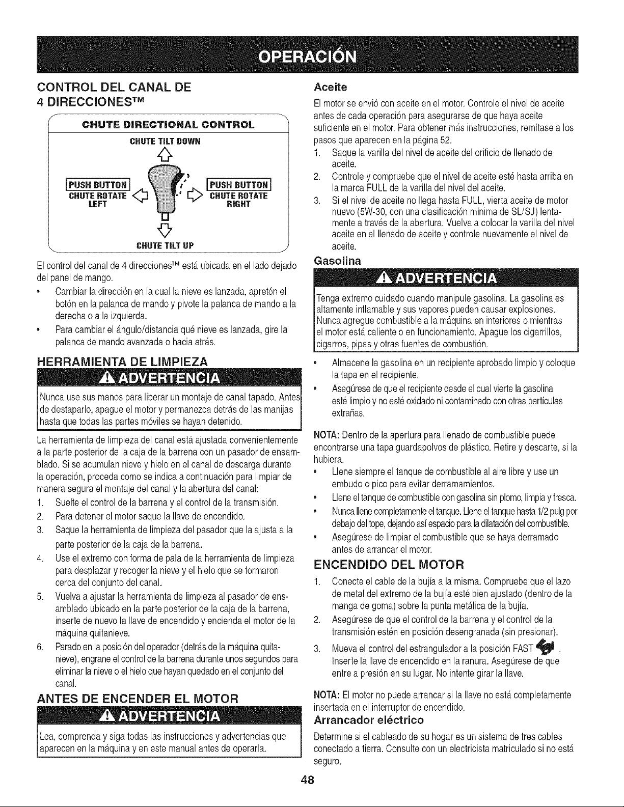
CONTROL DEL CANAL DE
4 DIRECCIONESTM
f
CHUTE DIRECTIONAL CONTROL
CHUTETiLTUOWN
0
IP.s.B.TTOHI IP.s.B.TTOHI
CHUTEROTATE I=,t> CHUTEROTATE
LEFT _ RIGHT
©
CHUTE TiLT UP j
Elcontroldel canalde 4 direccionedMestaubicadaenel ladodejado
delpaneldemango.
• Cambiarladirecci6nen la cualla nievees lanzada,apret6nel
bot6nen la palancade mandoy pivotela palancademandoa la
derechao a la izquierda.
,, Paracambiarel _mgulo/distanciaque nievees lanzada,girela
palancade mandoavanzadao haciaatr_ts.
HERRAMIENTA DE LIMPIEZA
Nuncausesus manosparaliberar un montajede canaltapado.Ante._
dedestaparlo,apagueel motory permanezcadetr_.sde las manijas
[hastaque todas as partesm6v es se hayandetendo.
La herramientadelimpiezadelcanalest,. ajustadaconvenientemente
a laparte posteriorde la caja dela barrenaconun pasadorde ensam-
blado.Si se acumulannievey hieloen elcanalde descargadurante
laoperaci6n,procedacomose indicaa continuaci6npara limpiarde
manerasegurael montajedel canaly la aberturadel canal:
1. Suelteel controlde la barrenay el controlde la transmisi6n.
2. Paradetenerel motorsaquela Ilavede encendido.
3. Saquela herramientade limpiezadelpasadorque la ajusta a la
parteposteriorde la cajade la barrena.
4. Useelextremoconformade pala de la herramientade limpieza
paradesplazary recogerla nievey el hieloquese formaron
cercadel conjuntodel canal.
5. Vuelvaa ajustarla herramientade limpiezaal pasadordeens-
ambladoubicadoen la parteposteriorde la caja de la barrena,
insertede nuevola Ilavede encendidoy enciendael motorde la
m_tquinaquitanieve.
6. Paradoenlaposici6ndeloperador(detr_tsde la m_tquinaquita-
nieve),engraneelcontroldelabarrenaduranteunossegundospara
eliminarla nieveoel hieloquehayanquedadoen el conjuntodel
canal.
ANTES DE ENCENDER EL MOTOR
Lea,comprenday sigatodas las instruccionesy advertenciasque
aparecenen la m_tquinay en este manualantesdeoperarla.
Aceite
Elmotorse envi6con aceiteenel motor.Controleel niveldeaceite
antesdecada operaci6nparaasegurarsedequehayaaceite
suficienteenel motor.Paraobtenerm_tsinstrucciones,remitasea los
pasosqueaparecenen la p_tgina52.
1. Saquelavarilladel nivelde aceitedel orificio de Ilenadode
aceite.
2. Controley compruebeque el nivelde aceite estehastaarribaen
lamarcaFULLdela varilladel niveldel aceite.
3. Si el nivelde aceite no Ilegahasta FULL,viertaaceitede motor
nuevo(5W-30,con unaclasificaci6nminimade SL/SJ)lenta-
mentea travesde la abertura.Vuelvaa colocarlavarilladel nivel
aceiteenel Ilenadode aceitey controlenuevamenteel nivelde
aceite.
Gasolina
Tengaextremocuidadocuandomanipulegasolina.La gasolinaes
altamenteinflamabley susvaporespuedencausarexplosiones.
Nuncaagreguecombustiblea la m_.quinaen interioreso mientras
el motorestercalienteo enfuncionamiento.Apagueloscigarrillos,
cigarros,pipasy otras fuentesde combustbn.
,, Almacenelagasolinaen un recipienteaprobadolimpioy coloque
latapaen el recipiente.
,, Aseg0resedequeel recipientedesdeel cualviertela gasolina
est_limpioy noest_oxidadoni contaminadoconotrasparticulas
extrahas.
NOTA:Dentrode la aperturaparaIlenadode combustiblepuede
encontrarseunatapa guardapolvosde pl_tstico.Retirey descarte,si la
hubiera.
,, Llenesiempreel tanquede combustibleal aire librey use un
embudoo picoparaevitarderramamientos.
,, Lleneeltanquedecombustiblecongasolinasinplomo,limpiay fresca.
,, NuncaIlenecompletamenteeltanque.Lleneeltanquehasta1/2pulgpor
debajodeltope,dejandoasiespacioparala dilataci6ndelcombustible.
,, Aseg0resede limpiarel combustibleque se hayaderramado
antesdearrancarel motor.
ENCENDIDO DEL MOTOR
1. Conecteel cablede la bujiaa lamisma.Compruebequeel lazo
de metaldelextremode la bujia este bien ajustado(dentrode la
mangade goma)sobrela puntamet_tlicade la bujia.
2. Aseg0resede queelcontrolde la barrenay elcontroldela
transmisi6nestenen posici6ndesengranada(sin presionar).
3. Muevael controldel estranguladora la posici6nFAST'_.
Insertela Ilavede encendidoenla ranura.Aseg0resede que
entrea presi6nen su lugar.No intentegirarla Ilave.
NOTA:El motorno puedearrancarsi laIlavenoestdtcompletamente
insertadaenel interruptordeencendido.
Arrancador el_ctrico
Determinesi elcableadode su hogares un sistemade tres cables
conectadoa tierra.Consultecon un electricistamatriculadosi no ester
seguro.
48
Elarrancadorelectricoopcionalest,.equipadocon un cable deali-
mentaci6ny un enchufede tres terminalesconectadosa tierray ester
disehadopara operarcon corrientedom_sticade 120voltios.Debe
serutilizadocon un recept_.culode tres terminalescorrectamente
conectadoa tierraen todomomentoparaevitarlaposibilidadde
descargaselectricas.Sigatodaslas instruccionescuidadosamente
paraoperarelarrancadorelectrico.
Si cuentaconun recept_tculode tres terminales,siga lossiguientes
pasos:
1. Conecteel prolongadora la salidasituadaen la superficiedel
motor.Conecteel otroextremodel prolongadoren unrecept_.culo
deCA conconexi6na tierra detresterminalesde 120voltios,en
un_.reabien ventilada.
2. Gireelcontrolde obturaci6na posici6ndeobturaci6nFULL
IJl (paraencendidocon el motorenfifo).
NOTA:si el motorya estacaliente,ubiqueelcontroldel obturadoren
posici6nOFFen lugardeFULLIJl •
3. Presioneel cebadordos otres vecespara arrancarel motoren
fifo, asegur_tndosede cubrirel orificiode ventilaci6nsituadoen
el centrodel cebadorcuandoestepresionando.
NOTA:NO UTILICEel cebadorparareiniciarun motorcalientetras
unadetenci6nbreve.
4. Presioneel bot6ndel arrancadorparaarrancarel motor.
NOTA:NOmantengael bot6noprimidodurantem_.sdesiete(7)
segundosa la vez.Si Iohace,puededaharel arrancadorelectricodel
motor.
5. Unavezencendidoel motor,suelteelbot6ndel arrancador.
6. Mientrasse calientael motor,gire lentamenteel controldel obtu
radora posici6nOFF(apagado).Si el motorfalla,vuelva a girar
r_.pidamenteel obturadora posici6nFULL I,,_¢I y luego,
lentamente,a posici6nOFFde nuevo.
7. Cuandodesconecteel prolongador,desenchufesiempreel
extremodel recept_tculode tres terminalesen eltomacorriente
de paredantesdedesenchufarel extremoopuestodela
m_tquinaquitanieve.
Arrancador de retroceso
1. Gireelcontrolde obturaci6na posici6ndeobturaci6nFULL
I,_'1 (encendidocon el motoren fifo).
NOTA:Isi el motorya estercaliente,ubique el controldel obturadoren
posici6nOFFen lugardeFULLIJl •
2. Presioneel cebadordos otres vecespara arrancarel motoren
fifo, asegur_tndosede cubrirel orificiode ventilaci6nsituadoen
el centrodel cebadorcuandoestepresionando.
NOTA:NO UTILICEel cebadorparareiniciarun motorcalientetras
unadetenci6nbreve.
NOTA:talvez sea necesarioun cebadoadicionalsi latemperaturaes
inferiora 15° Fahrenheit.
3. Tome la manijadel arrancadorderetrocesoy tire de la cuerda
haciaafueralentamente.En el momentoen el quese haga
levementem_.sdificiltirarde la cuerda,permitaque lamisma
retrocedalentamente.
4. Tire de la manijadelarrancadorcon un movimientofirme y
r_tpido.Nosueltelamanijani permitaquese desenganche.
Mantengala manijadel arrancadorfirmementesujetay permita
quela cuerdaretrocedalentamente.
5. Mientrasse calientael motor,gire lentamenteel control del
obturadora posici6nOFF (apagado).Siel motorfalla,vuelvaa
girarr_tpidamenteel obturadora posici6nFULL Ill Y luego,
lentamente,a posici6nOFFde nuevo.
NOTA:permitaque el motorse calienteduranteunosminutostrasel
arranque.El motorno desarrollar_ttodasu potenciahastaque alcance
temperaturasoperativas.
DETENCION DEL MOTOR
Dejeencendidoel motordurantealgunosminutosantesde detenerlo
parapermitirquese sequela humedaden elmismo.
1. Muevael controldelestranguladora la posici6nSTOP_.
2. Retirela Ilavede encendidoy gu_.rdelaen un lugar seguro.
3. Limpiela nievey la humedaddel &reaalrededordel motor,ad
comotambienenel &rea(y alrededorde esta) del interiorde los
controlesde la transmisi6ny de la barrena.Asimismo,enganche
y suelteamboscontrolesvariasveces.
PROCEDIMIENTO PARA ENGRANAR LA
TRANSMISION
1. Con el control del estranguladoren posici6nr_.pida'_ (dibujo
de unconejo),muevala palancade cambiosa una de las seis
posicionesde avance(F) o de lasdos posicionesdereversa(R).
Seleccionelavelocidadadecuadapara el estadode la nieveexis-
tentey unavelocidadconla que se sientac6modo.
NOTA:AIseleccionarunavelocidadde latransmisi6n,use las veloci-
dadesm_tslentashastaquese sientac6modoy se hayafamiliarizado
con el funcionamientode la m_tquinaquitanieve.
2. Aprieteel controlde la transmisi6ncontrala manijaderecha,y la
m_.quinaquitanievese mover& Suelteloy se detendr_tel
movimientode latransmisi6n.
NOTA:NUNCAcambie la posici6nde la palancade cambios(cambio
de velocidadeso de direcci6nde desplazamiento)sin soltarprimeroel
controlde transmisi6ny detenerpor completola m_.quinaquitanieve.
Estoproducir_tundesgasteprematurodel sistemade transmisi6nde
lam_tquinaquitanieve.
PROCEDIMIENTO PARA ENGRANAR LAS
BARRENAS
1. Aprieteel control de la barrenacontra la manijay las barrenas
rotaran.Sueltelay lasbarrenasse detendran.
49
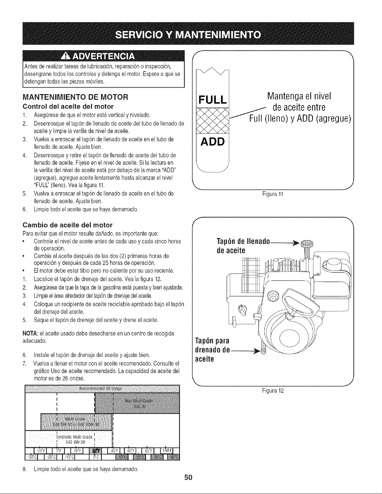
Antesde realizartareasde lubricaci6n,reparaci6no inspecci6n,
desengranetodoslos controlesy detengael motor.Esperea quese
_detengantodas as pezasm6v es.
MANTENIMIENTO DE MOTOR
ControJ del aceite del motor
1. AsegOresede queel motorestAverticaly nivelado.
2. Desenrosqueel tap6nde Ilenadode aceitedeltubo de Ilenadode
aceitey limpiela varillade nivelde aceite.
3. Vuelvaa enroscarel tap6nde Ilenadode aceiteen eltubo de
Ilenadode aceite.Ajustebien.
4. Desenrosquey retireel tap6n deIlenadode aceite del tubo de
Ilenadode aceite.Fijese en el nivelde aceite.Si la lecturaen
la varilladel nivelde aceite esta por debajode la marca"ADD"
(agregue),agregueaceite lentamentehastaalcanzarel nivel
"FULl" (lleno).Vealafigura 11.
5. Vuelvaa enroscarel tap6nde Ilenadode aceiteen eltubo de
Ilenadode aceite.Ajustebien.
6. Limpietodo elaceitequese hayaderramado.
FULL
ADD
Mantenga el nivel
de aceite entre
--"fFull (lleno) y ADD (agregue)
Figura11
J
Cambio de aceite del motor
Paraevitarqueel motorresultedahado,es importanteque:
,, Controleel nivelde aceiteantesde cadauso y cadacincohoras
deoperaci6n.
,, Cambieel aceitedespuesde lasdos (2) primerashorasde
operaci6ny despuesdecada25 horasde operaci6n.
,, Elmotordebeestartibio pero no calientepor su usoreciente.
1. Localiceel tap6nde drenajedel aceite.Veala figura12.
2. AsegOresedequelatapadelagasolinaestApuestay bienajustada.
3. Limpieel Areaalrededordeltap6ndedrenajedelaoeite.
4. Coloqueun recipientede aceite reciclableaprobadobajoel tap6n
deldrenajedelaceite.
5. Saqueeltap6n de drenajedelaceitey dreneel aceite.
NOTA:el aceite usadodebedesecharseen un centrode recogida
adecuado.
6,
7.
Instaleel tap6n de drenajedel aceitey ajustebien.
Vuelvaa Ilenarel motorcon el aceiterecomendado.Consulteel
graficoUsode aceiterecomendado.La capacidadde aceite del
motores de 26 onzas.
Tap6n de Ilenad0-----_
de aceite
Tap6n para
drenado de
aceite
Figura12
I
Syn!hetic Multi Grade i
SAE 0W-30 j
8. Limpietodoel aceiteque se hayaderramado.
5O
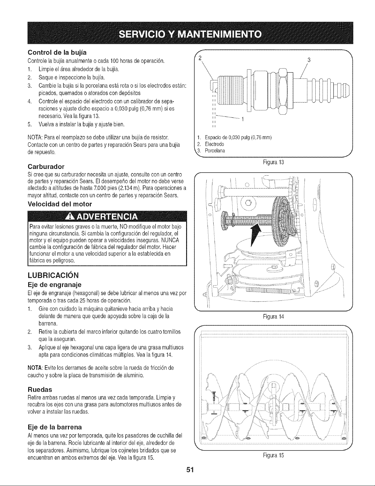
Control de la bujia
Controlelabujia anualmenteo cada 100 horasde operaci6n.
1. Limpieel _.reaalrededorde labujfa.
2. Saquee inspeccionela bujia.
3. Cambielabujiasi laporcelanaesta rotao si loselectrodosest_m:
picados,quemadoso atoradoscon dep6sitos
4. Controleel espaciodelelectrodocon un calibradorde sepa-
racionesy ajustedichoespacioa 0,030pulg (0,76mm) si es
necesario.Vea la figura13.
5. Vuelvaa instalarla bujiay ajustebien.
NOTA:Parael reemplazose debeutilizarunabujiaderesistor.
Contactecon un centro de partesy reparaci6nSearsparaunabujia
de repuesto.
Carburador
Si creequesu carburadornecesitaun ajuste,consultecon uncentro
departesy reparaci6nSears.Eldesempehodelmotorno debeverse
afectadoa altitudesde hasta7.000pies (2.134m). Para operacionesa
mayoraltitud,contactecon un centrode partesy reparaci6nSears.
Velocidad del motor
Paraevitarlesionesgraveso la muerte,NO modifiqueel motorbajo
ningunacircunstancia.Sicambialaconfiguraci6ndel regulador,el
motory elequipopuedenoperara velocidadesinseguras.NUNCA
cambiela configuraci6nde f_.bricadel reguladordel motor.Hacer
funcionarel motora unavelocidadsuperiora la establecidaen
f_tbricaes peligroso.
LUBRICACI()N
Eje de engranaje
Elejede engranaje(hexagonal)se debelubricaral menosunavezpor
temporadao tras cada25horasde operaci6n.
1. Gireconcuidadola m_tquinaquitanievehaciaarriba y hacia
delantede maneraquequedeapoyadasobrela cajade la
barrena.
2. Retirela cubiertadelmarcoinferiorquitandolos cuatrotornillos
quela aseguran.
3. Apliquealeje hexagonaluna capa ligerade unagrasa multiusos
aptapara condicionesclim_tticasmOltiples.Vealafigura 14.
NOTA:Evitelos derramesde aceite sobrela ruedade fricci6nde
cauchoy sobrela placade transmisi6nde aluminio.
Ruedas
Retireambasruedasal menosunavez cada temporada.Limpiey
recubralosejescon una grasapara automotoresmultiusosantesde
volvera instalarlas ruedas.
Eje de la barrena
AI menosunavez por temporada,quitelos pasadoresde cuchilladel
ejede labarrena.Rode lubricanteal interiordel eje,alrededorde
los separadores.Asimismo,lubriquelos cojinetesbridadosquese
encuentranen ambosextremosdel eje.Vea la figura 15.
f --,,
2 3
II
II
II
1. Espaciode0,030pulg(0,76ram)
2. Electrodo
3. Porcelana
Figura 13
J
'I
Figura14
_.. j
Figura15
51
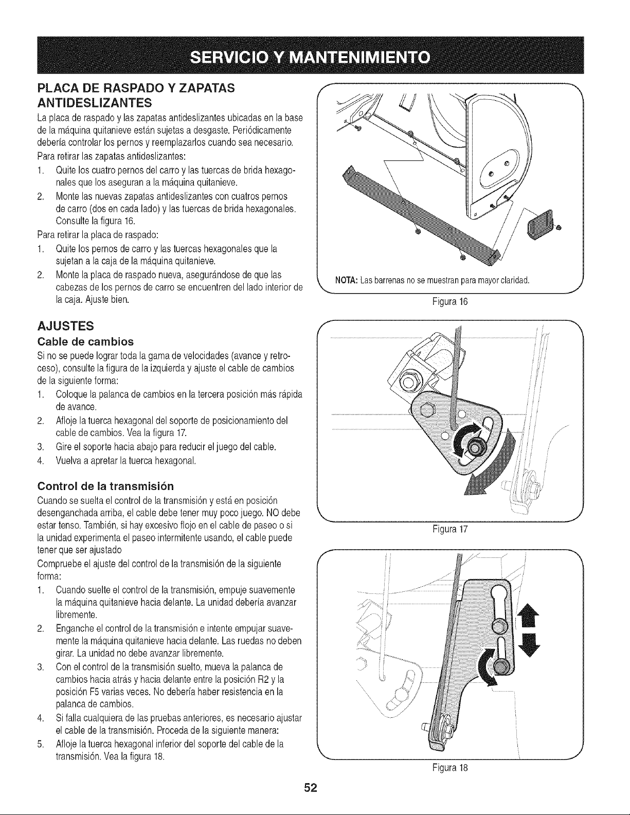
PLACA DE RASPADO Y ZAPATAS
ANTIDESLIZANTES
Laplacade raspadoy laszapatasantideslizantesubicadasen la base
de lam_.quinaquitanieveest_tnsujetasa desgaste.Peri6dicamente
deberiacontrolarlospernosy reemplazarloscuandosea necesario.
Pararetirarlas zapatasantideslizantes:
1. Quitelos cuatropernosdel carroy lastuercasde bridahexago-
nalesque los asegurana la m_tquinaquitanieve.
2. Montelas nuevaszapatasantideslizantesconcuatrospernos
decarro (dosen cada lado)y las tuercasde bridahexagonales.
Consultela figura 16.
Pararetirarla placade raspado:
1. Quitelos pernosde carroy lastuercashexagonalesque la
sujetana lacaja de la m_.quinaquitanieve.
2. Montela placade raspadonueva,asegur_.ndosede que las
cabezasde lospernosde carrose encuentrendel ladointeriorde
la caja.Ajustebien.
f --,,
NOTA:Las barrenasno se muestranparamayorclaridad.
Figura 16
AJUSTES
Cable de cambios
Si nose puedeIogrartoda la gamade velocidades(avancey retro-
ceso),consultela figuradela izquierday ajusteel cablede cambios
de lasiguienteforma:
1. Coloquela palancade cambiosen la terceraposici6nm_tsr_tpida
deavance.
2. Aflojelatuerca hexagonaldelsoportede posicionamientodel
cablede cambios.Vea la figura 17.
3. Gireelsoportehaciaabajopara reducirel juegodelcable.
4. Vuelvaa apretarlatuerca hexagonal.
Control de la transmision
Cuandose sueltael controlde latransmisi6ny est,. en posici6n
desenganchadaarriba,el cabledebe tenermuy pocojuego. NOdebe
estartenso.Tambien,si hayexcesivoflojoen el cablede paseoo si
la unidadexperimentael paseointermitenteusando,el cable puede
tenerque serajustado
Compruebeel ajustedel controlde latransmisi6ndela siguiente
forma:
1. Cuandosuelteel controlde la transmisi6n,empujesuavemente
la maquinaquitanievehaciadelante.La unidaddeberiaavanzar
libremente.
2. Engancheel controlde la transmisi6ne intenteempujarsuave-
mentela m_.quinaquitanievehaciadelante.Las ruedasno deben
girar.La unidadno debe avanzarlibremente.
3. Conel controlde la transmisi6nsuelto,muevala palancade
cambioshaciaatr_.sy haciadelanteentrela posici6nR2 y la
posici6nF5variasveces. No deberiahaberresistenciaen la
palancade cambios.
4. Sifalla cualquierade las pruebasanteriores,es necesarioajustar
el cablede latransmisi6n.Procedade la siguientemanera:
5. Aflojela tuerca hexagonalinferiordel soportedel cablede la
transmisi6n.Yea la figura 18.
J
Figura17
f
J
Figura18
52
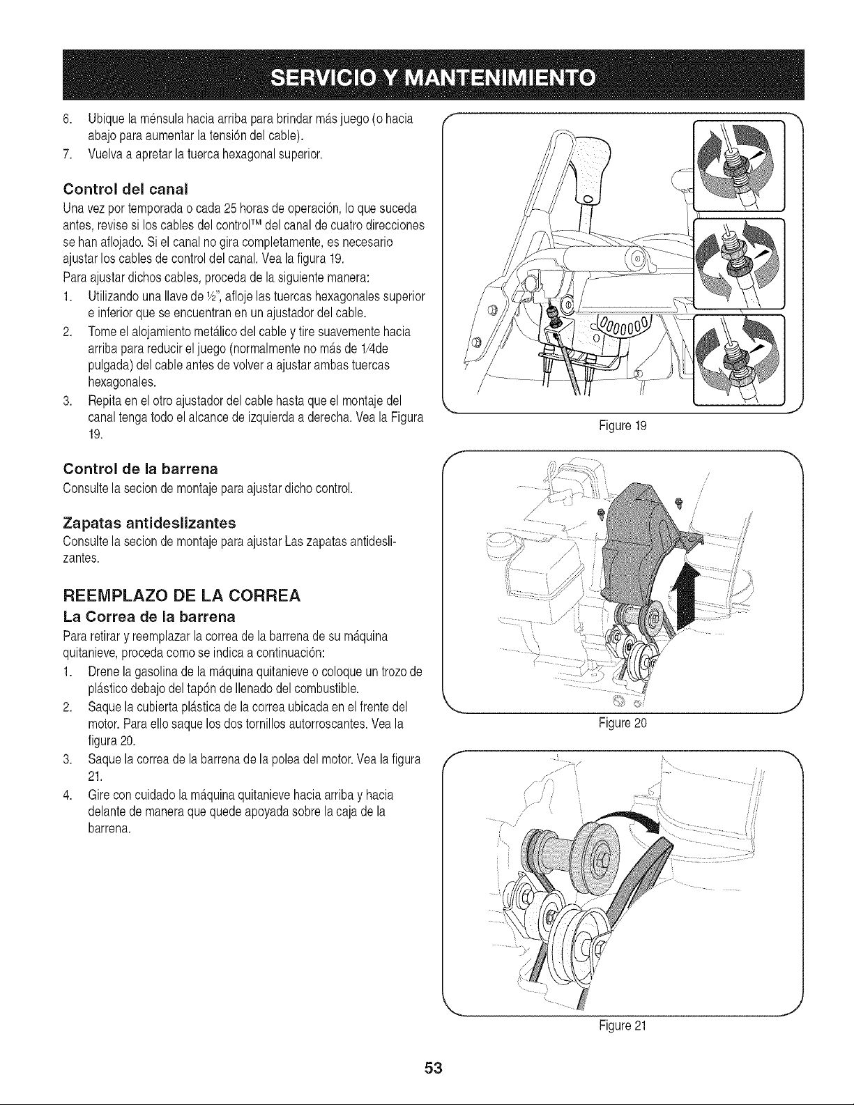
6. Ubiquela m_nsulahaciaarribapara brindarm_tsjuego(o hacia
abajoparaaumentarla tensi6ndelcable).
7. Vuelvaa apretarla tuercahexagonalsuperior.
Control del canal
Unavez por temporadao cada25 horasde operaci6n,Io que suceda
antes,revisesi los cablesdelcontrolTM del canalde cuatrodirecciones
se han aflojado.Si el canalno gira completamente,es necesario
ajustarlos cablesde control del canal.Vea la figura19.
Paraajustardichoscables,procedadela siguientemanera:
1. Utilizandouna Ilavede 1/2",aflojelas tuercashexagonalessuperior
e inferiorque se encuentranen unajustadordelcable.
2. Tomeel alojamientomet_.licodelcabley tire suavementehacia
arribaparareducirel juego (normalmentenom_.sde 1/4de
pulgada)del cableantesde volvera ajustarambastuercas
hexagonales.
3. Repitaen elotro ajustadordel cable hastaqueel montajedel
canaltengatodo el alcancede izquierdaa derecha.Veala Figura
19.
Control de la barrena
Consultela secion de montajepara ajustardichocontrol.
Zapatas antideslizantes
Consultela secion de montajepara ajustarLaszapatasantidesli-
zantes.
REEMPLAZO DE LA CORREA
La Correa de la barrena
Pararetirary reemplazarla correade la barrenade su m_tquina
quitanieve,procedacomose indicaa continuaci6n:
1. Drenela gasolinade la m_tquinaquitanieveo coloqueuntrozode
pl_.sticodebajodel tap6nde Ilenadodel combustible.
2. Saquela cubiertapl_tsticade lacorreaubicadaen el frentedel
motor.Paraello saque losdos tornillosautorroscantes.Vea la
figura20.
3. Saquela correade la barrenade la polea del motor.Yealafigura
21.
4. Gireconcuidadola m_tquinaquitanievehaciaarriba y hacia
delantede maneraquequedeapoyadasobrela cajade la
barrena.
f
Figure19
/
/
f
Figure20
J
Figure21
J
53
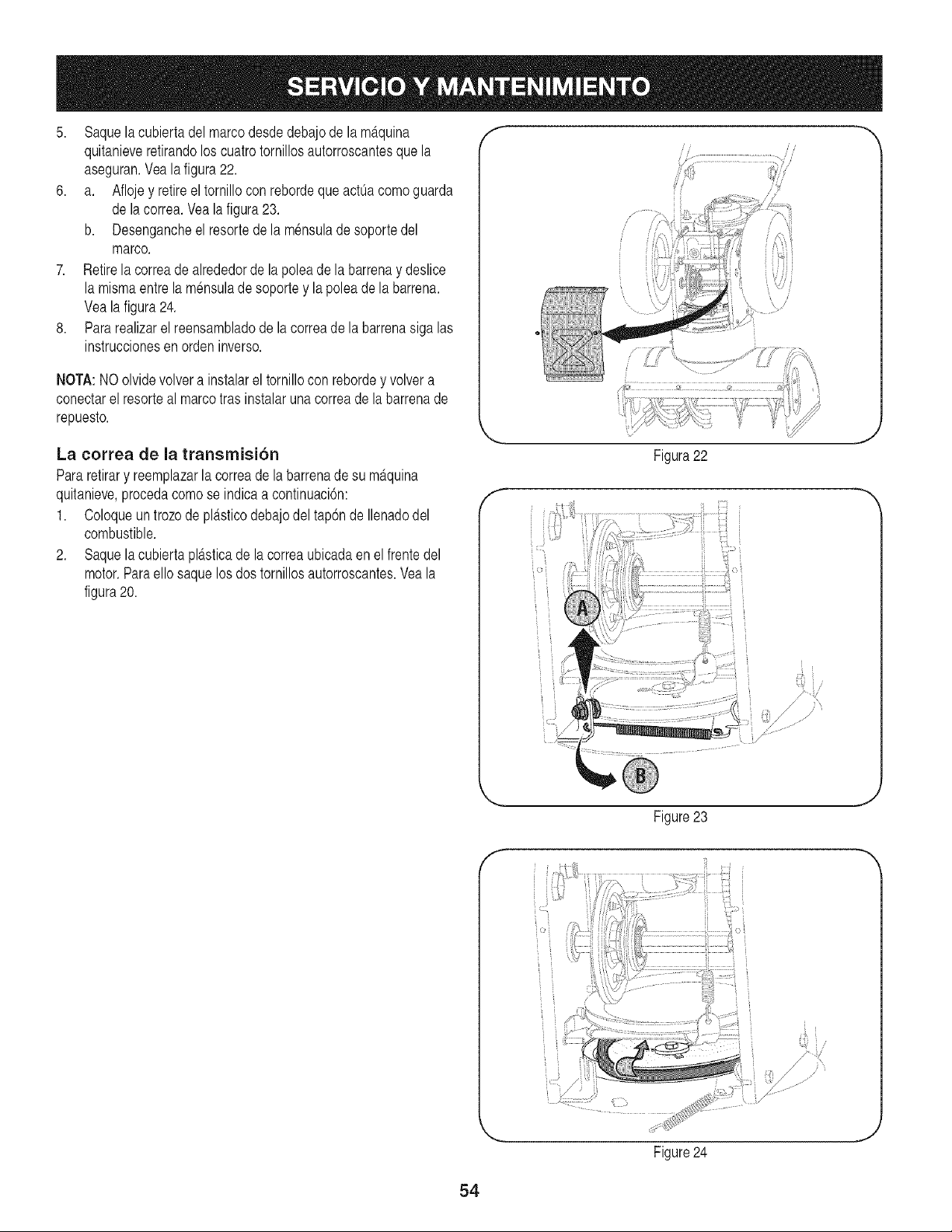
5. Saquelacubiertadelmarcodesdedebajode la m_.quina
quitanieveretirandoloscuatro tornillosautorroscantesque la
aseguran.Vealafigura22.
6. a. Aflojey retireel tornilloconrebordeque actOacomoguarda
de lacorrea.Vealafigura23.
b. Desengancheel resortede la m6nsulade soportedel
marco.
7. Retirelacorreade alrededorde la poleade la barrenay deslice
la mismaentre lam6nsulade soportey lapoleadela barrena.
Vealafigura24.
8. Pararealizarel reensambladode la correade la barrenasiga las
instruccionesen orden inverso.
NOTA:NOolvidevolvera instalarel tornillocon rebordey volver a
conectarel resorteal marcotras instalaruna correade la barrenade
repuesto.
La correa de la transmision
Pararetirary reemplazarla correade la barrenade su m_tquina
quitanieve,procedacomose indicaa continuaci6n:
1. Coloqueun trozo de pl_tsticodebajodel tap6nde Ilenadodel
combustible.
2. SaquelacubiertaplD.sticade la correaubicadaen el frentedel
motor.Paraello saquelosdos tornillosautorroscantes.Veala
figura20.
f m
Figura22
f
• i
f
Figure23
_J
Figure24
i:_i i •
.J
54
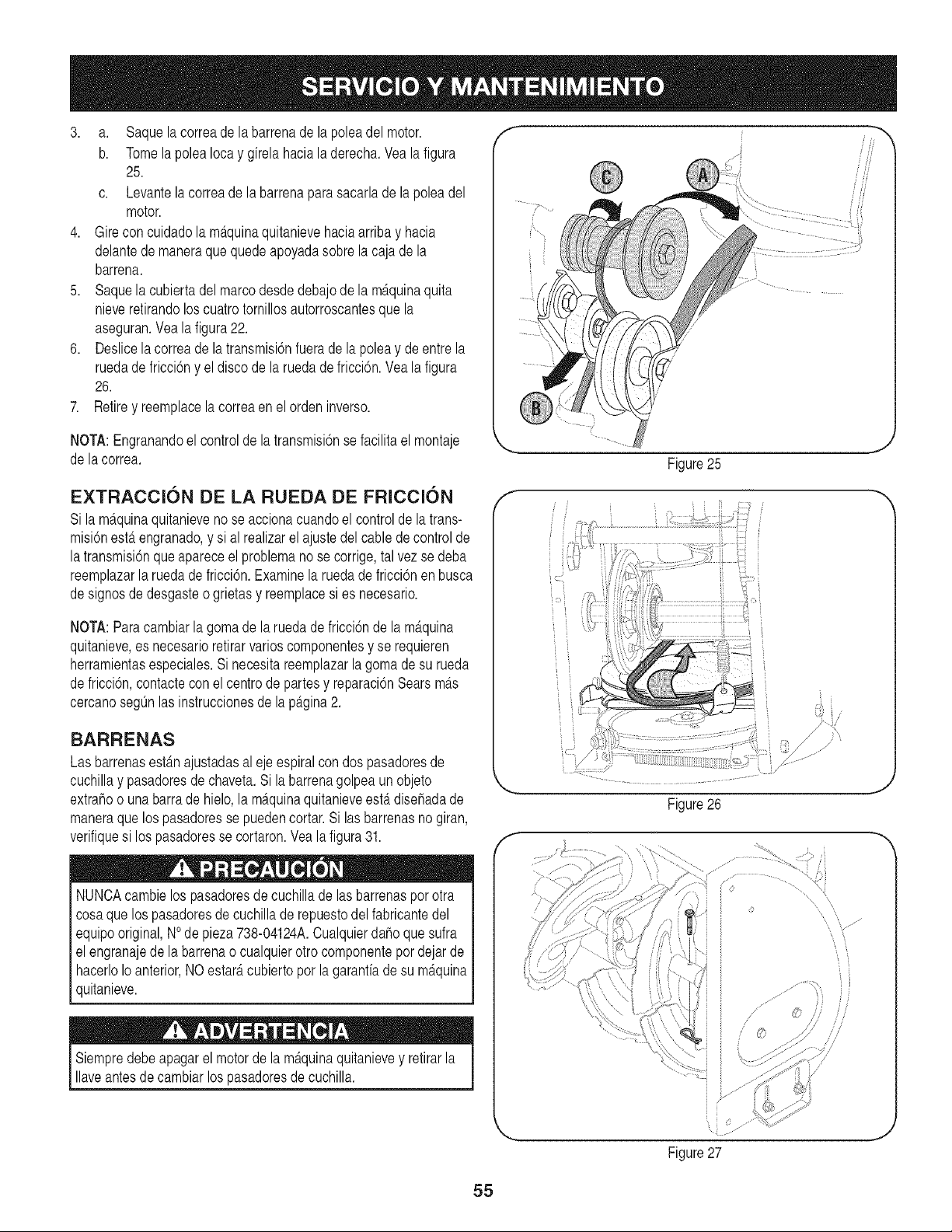
3. a. Saquela correade labarrenade la poleadel motor.
b. TomelapoleaIocay girelahaciala derecha.Vea la figura
25.
c. Levantela correade la barrenapara sacarlade la polea del
motor.
4. Girecon cuidadola m_tquinaquitanievehaciaarriba y hacia
delantede maneraquequedeapoyadasobrela cajade la
barrena.
5. Saquela cubiertadelmarcodesdedebajode la m_tquinaquita
nieveretirandoloscuatrotornillosautorroscantesque la
aseguran.Veala figura22.
6. Deslicelacorreade latransmisi6nfuerade la poleay de entre la
ruedade fricci6ny el disco de la ruedade fricci6n.Yea la figura
26.
7. Retirey reemplacela correaen el orden inverso.
NOTA:Engranandoel controlde la transmisi6nse facilitael montaje
de lacorrea.
EXTRACClON DE LA RUEDA DE FRICClON
Si lam_.quinaquitanievenose accionacuandoel control de la trans-
misi6nest,.engranado,y sial realizarelajustedel cabledecontrolde
latransmisi6nqueapareceel problemanose corrige,tal vezse deba
reemplazarlaruedadefricci6n.Examinela ruedadefricci6nen busca
designosde desgasteo grietasy reemplacesi es necesario.
NOTA:Paracambiarla gomade la ruedade fricci6nde la m_tquina
quitanieve,es necesarioretirarvarioscomponentesy se requieren
herramientasespeciales.Si necesitareemplazarla gomade su rueda
defricci6n,contactecon el centro de partesy reparaci6nSearsm_ts
cercanosegOnlasinstruccionesde lap_tgina2.
f
BARRENAS
Las barrenasestdmajustadasalejeespiralcon dospasadoresde
cuchillay pasadoresde chaveta.Si la barrenagolpeaun objeto __
extrahoo unabarrade hielo,la m_.quinaquitanieveest,. disehadade
maneraque los pasadoresse puedencortar.Si las barrenasnogiran,
verifiquesi los pasadoresse cortaron.Vea la figura 31. f
i
J
Figure25
Figure26
J
J
NUNCAcambielos pasadoresde cuchillade lasbarrenasporotra
cosaquelos pasadoresde cuchillade repuestodel fabricantedel
equipooriginal,NOde pieza738-04124A.Cualquierdaho que sufra
el engranajede labarrenao cualquierotrocomponentepordejarde
hacerloIoanterior,NOestar_tcubiertoporlagaranfiade su m_tquina
quitanieve.
ii
Figure27
,J
55
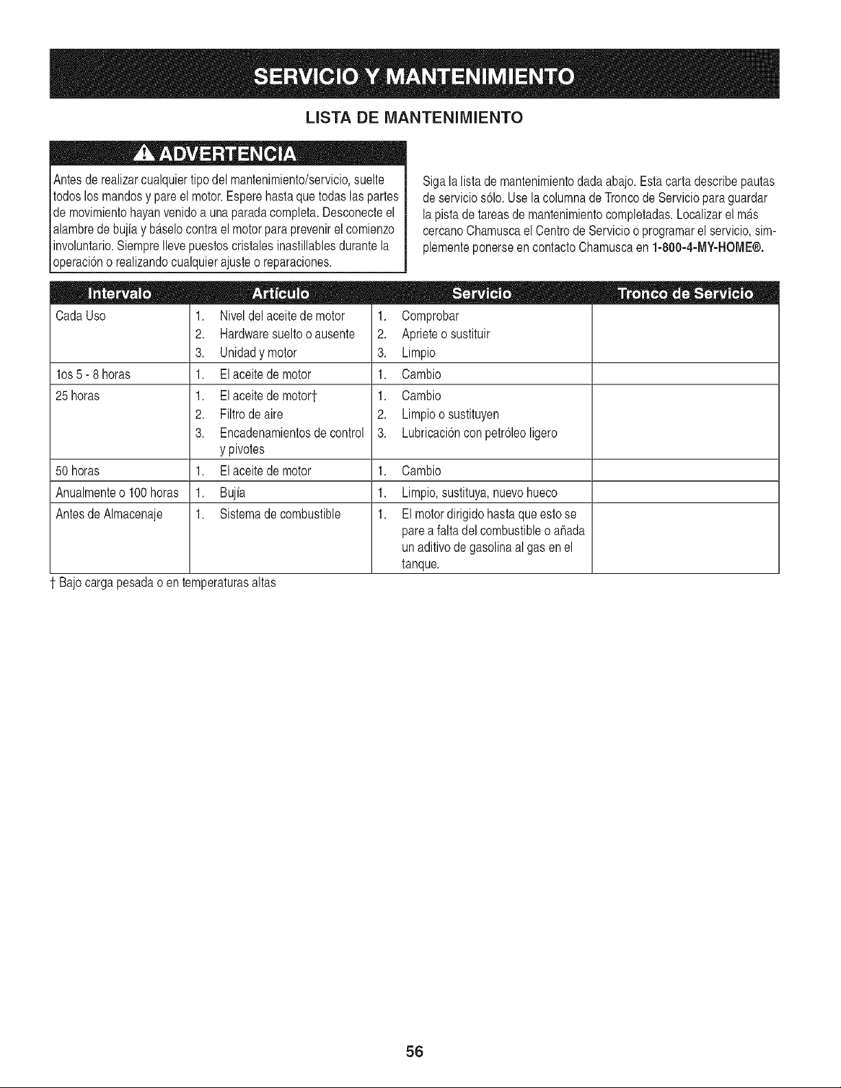
LISTA DE MANTENIMIENTO
Antesde realizarcualquiertipo del mantenimiento/servicio,suelte
todoslos mandosy pare el motor.Esperehastaquetodaslas partes
de movimientohayanvenidoa unaparadacompleta.Desconecteel
alambrede bujia y b_tselocontrael motorparaprevenirel comienzo
involuntario.SiempreIlevepuestoscristalesinastillablesdurantela
operaci6no realizandocualquierajusteo reparaciones.
CadaUso
los 5- 8 horas
25 horas
1. Niveldel aceitede motor
2. Hardwaresueltooausente
3. Unidadymotor
1. Elaceite demotor
1. Elaceite demotor1.
2. Filtrode aire
3. Encadenamientosdecontrol
y pivotes
1. Elaceite demotor
1. Bujia
1. Sistemadecombustible
Sigala listade mantenimientodadaabajo.Esta carta describepautas
de servicios61o.Use la columnade Troncode Servicioparaguardar
lapistadetareasde mantenimientocompletadas.Localizarel m_.s
cercanoChamuscaelCentrodeServicioo programarel servicio,sim-
plementeponerseen contactoChamuscaen 1-800-4-MY-HOME®.
1. Comprobar
2. Aprieteosustituir
3. Limpio
1. Cambio
1. Cambio
2. Limpioosustituyen
3. Lubricaci6ncon petr61eoligero
50 horas 1. Cambio
Anualmenteo 100horas 1. Limpio,sustituya,nuevohueco
Antesde Almacenaje 1. El motordirigidohastaqueestose
parea faltadelcombustibleo ahada
un aditivodegasolinaal gas enel
tanque.
1 Bajocargapesadao en temperaturasaltas
56
Sinosevaa utilizael equipodurante30diasomAs,o si esel finaldelatemporadadenieveyya noexisteposibilidaddequenieve,esnecesario
almacenarelequipodemaneraadecuada.Sigalas instruccionesde almacenamientoquese indicana continuaci6nparagarantizarelrendimiento
mAximode la mAquinaquitanievedurantemuchosahos.
PREPARACION DEL MOTOR
Almacenaje a Corto plazo
Es importanteevitarqueduranteel almacenamientose formendep6si-
tosdegomaen laspiezas esencialesdelsistemade combustibledel
motorcomo,por ejemplo,en el carburador,el filtro de combustible,la
manguerade combustibleo el dep6sito.
Eluso de estabilizadoresde combustible(comoSTA-BIL)es unaal-
ternativaaceptablepara minimizarla formaci6nde dep6sitosdegoma
decombustibleduranteel almacenamiento.Agregueel estabilizador
a lagasolinaque se encuentraen el dep6sitode combustibleo en
elrecipientede almacenamiento.Respetesiemprelaproporci6nde
mezcladoque figuraen el recipientedel estabilizador.Pongael motor
enmarchaporIo menos10 minutosdespuesdeagregarel estabiliza-
dorparapermitirleIlegaral carburador.Nodrene el carburadorsi esta
utilizandounestabilizadorde combustible.
PREPARACION DE LA MAQUINA QUITANIEVE
1. Cuandoalmacenela mAquinaquitanieveen ungalp6nde
dep6sitometAlicoo con pocaventilaci6n,tengaespecialcuidado
de realizarleun tratamientoanti- oxidanteal equipo.Useaceite
ligeroo silic6npararecubrirel equipo,especialmentelas
cadenas,losresortes,loscojinetesy los cables.
2. Eliminetodoel polvodel exteriordel motory del equipo.
3. Siga lasrecomendacionesde lubricaci6nen la secci6nde
mantenimientodeestemanual.
4. Almaceneel equipoen unAreadespejaday seca.
Nuncaalmacenela maquinaquitanievecon combustibleen el
tanqueen un espaciocerradoo en Areascon pocaventilaci6n,
dondelosgases del combustiblepuedanalcanzarel fuego,chispas
o unaluz pilotocomola que tienenalgunoshornos,calentadoresde
agua,secadoresde ropao agOnotro d spost vo a gas.
Alos combustiblescon mezclade alcohol(que se Ilamangasohol,
o queutilizanetanolo metanol)puedenatraerla humedad,Io que
conducea la separaci6ny formaci6nde acidosduranteel almace-
namiento.El gas addico puede daharel sistemadel combustiblede
unmotorduranteel almacenamientodel mismo.
Almacenaje a Largo plazo
Paraevitarproblemascon el motor,el sistemadel combustibledebe
servaciadoantesde almacenarla maquinadurante30 dias o mas.
Elcombustibleque sedeje en el motorse deterioracuandoel clima
es calidoy causagravesproblemasde encendido.
1. Pongaelmotorenmarchahastavaciareldep6sitode com-
bustibley hastaqueel motorse detengadebidoa la falta de
combustible.
Nuncause el motoro el carburadorquelimpiaproductosen el
dep6sitodecombustibleo eldahopermanentepuedeocurrir.
2.
Retirelabujiay vierta(1)onzade aceite para motora travesdel
orificiode labujiay haciael interiordelcilindro.Cubraelorificio
dela bujiacon un trapoy pongael motoren marchavariasveces
paradistribuirel aceite.Reemplacelabujia.
57
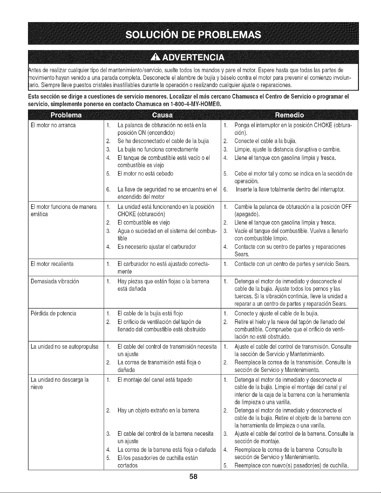
luier tipodel mantenimiento/servicio,sueltetodos los mandosy pareelmotor.Esperehastaque todas las partesde
Ilevepuestoscristalesinastillablesdurantela operaci6no realizandocualquierajusteo reparaciones.
Estasecci6nsedirigea cuestione$de serviciomenores, Localizarel mac cereanoChamuscael Centrode Servicio o programarel
servicio,simplementeponerseen contactoChamusca en 1-800-4-MY-HOME®.
El motor no arranca 1. /a palanea de obturacidn no estfi en la
posici6nON (encendido)
2. Sehadesconectadoel cablede la bujia
3. Labujiano funcionacorrectamente
4. Eltanquede combustibleestervado o el
combustiblees viejo
5. El motornoestercebado
6. La Ilavede seguridadno se encuentraenel
encendidodel motor
1. La unidadesterfuncionandoenla posici6n
CHOKE(obturaci6n)
2. Elcombustibleesviejo
3. Aguao suciedaden el sistemadel combus-
tible
4. Es necesarioajustarel carburador
1. Elcarburadorno esterajustadocorrecta-
mente
1. Haypiezasqueest_mflojas o la barrena
= = II •
1. Pongael interruptoren laposici6nCHOKE(obtura-
ci6n).
2. Conecteel cablea la bujia.
3. Limpie,ajusteladistanciadisruptivao cambie.
4. Lleneel tanquecongasolinalimpiay fresca.
5. Cebe el motortal y como se indicaen la secci6nde
operacibn.
6. Insertela Ilavetotalmentedentrodel interruptor.
1. Cambielapalancade obturaci6na la posici6nOFF
(apagado).
2. Lleneel tanquecongasolinalimpiay fresca.
3. Vacieel tanquedel combustible.Vuelvaa Ilenarlo
con combustiblelimpio.
4. Contactecon su centrode partesy reparaciones
Sears.
1. Contactecon un centrode partesy servicioSears.
El motorfuncionademanera
err_ttica
1. Elcablede la bujiaesterflojo
2. Elorificiode ventilaci6ndel tap6nde
Ilenadodel combustibleesterobstruido
El motorrecalienta
Demasiadavibraci6n
Perdidadepotencia
La unidadnose autopropulsa
La unidadnodescargala
nieve
1,
2.
1. Detengael motorde inmediatoy desconecteel
esterdahada cable de la bujia.Ajustetodos los pernosy las
tuercas.Si la vibraci6ncontinOa,Ilevela unidada
reparara un centrode partesy reparaci6nSears.
1. Conectey ajusteel cablede la bujia.
2. Retireel hieloy la nievedel tap6nde Ilenadodel
combustible.Compruebeque el orificiode venti-
laci6nno este obstruido.
Elcabledel controlde transmisi6nnecesita 1. Ajuste el cable del controlde transmisi6n.Consulte
unajuste
Lacorreade transmisi6nesterflojao
dahada
1. El montajedelcanalest_ttapado
2. Hayunobjetoextrahoen la barrena
lasecci6nde Servicioy Mantenimiento.
2. Reemplacela correade la transmisi6n.Consultela
secci6nde Servicioy Mantenimiento.
1. Detengael motorde inmediatoy desconecteel
cable de la bujia. Limpieel montajedel canaly el
interiorde la caja dela barrenacon la herramienta
de limpiezao unavarilla.
2. Detengael motorde inmediatoy desconecteel
cable de la bujia. Retireel objetode labarrenacon
la herramientadelimpiezao unavarilla.
3. Ajusteelcable del controlde la barrena.Consultela
secci6nde montaje.
4. Reemplacela correade la barrena Consultela
secci6nde Servicioy Mantenimiento.
5. Reemplacecon nuevo(s)pasador(es)de cuchilla.
3. Elcabledel controlde la barrenanecesita
unajuste
4. Lacorreade la barrenaest,. flojao dahada
5. El/lospasador/esde cuchillaest_m
cortados
58
(Esta p_tginase aplica s61oen EE.UU. y CanadA).
Sears, Roebuck and Co., LI.S.Ao (Sears), el Coneejo de Recureoe Ambientalee de California (CARB)
y la Agencia de Protecci6n Ambiental de los Eetados Unidoe (EPA)
Declaracion de garant[a del sieterna de control de emisionee (derechoe y obmigacionee de la garant[a de defectoe del propi-
etario)
LA COBERTURADELA GARANTfADE CONTROLDE EMISIONESES
APLICABLEA LOS MOTORESCERTIFICADOSCOMPRADOSEN CALIFOR-
NIAEN 1995Y POSTERIORMENTE,QUE SE UTILIZANENCALIFORNIA,
Declaracion de garantia sobre defectoe en el control
ElConsejode RecursosAmbientalesde California(CARB),la EPA(Agencia
de ProteccionAmbientalde los EE.UU.)y Searstienen el gustode explicarla
garantfadel sistemade control de emisionesparamotoresdel ado2000y para
elfuture con relaciona motorespequehostedo terreno(SORE).En California,
los nuevosmotorespequeSostodo terrenodebenestar diseSados,construidos
y equipadosparacumplircon las rigurosasnormasanti-smogdelestado.En
el restede losEstadosUnidos,losmotoresnuevostodoterrenode encendido
perchispa certificadosparael aSo1997debencumplirestAndaressimilares
establecidosper la EPA.Searsdebegarantizarel sistemade control de emis-
Y PARALOS MODELOSCERTIFICADOSDELAiqO 1997YPOSTERIORES,
QUESE COMPRENY UTILICENEN CUALQUIERPARTEDE LOSESTADOS
UNIDOS(Y A PARTIRDEL 1 DE ENERODE2001 EN CANAD,_).
de emisionee para California y los Eetadoe Unidoe
ionesde su motorparalos periodosde tiempo enumeradosa continuaci6n,
siemprequeno hayaabuse,negligenciao mantenimientoindebidodesu
motortodoterrenopeque_o.Su sistemade controlde emisionespuedeincluir
piezastales comeel carburador,el filtrodeaire, elsistemade encendido,el
silenciadory elconversercatalitico.Tambienpuede incluirconectoresy otras
unidadesrelacionadascon las emisiones.Dondeexistaunacondicioncubierta
perla garantfa,Searsrepararasu peque_omotortodo terrenosin costoalguno
incluyendodiagnostico,piezasy manede obra
Cobertura de la garantia Sears para defectoe en el control de ernieionee
Los motorestodo terrenopeque_osestangarantizadosen Io relativealcontrol alas disposicionesque se indiquena continuacion.Siuna partede su motor
de emisionesparadefectosenpiezasduranteun periodode dos ahos,sujeto cubiertaper la garantiaesdefectuosa,Sears repararao sustituiradicha parte.
Responeabilidadee del propietario en relacibn con la garantia
Comepropietariodel motortodo terrenopequeffo,Ud.es responsablede la
realizaciondel mantenimientorequeridoquese incluyeen las instrucciones
de operaciony mantenimiento.Sears recomiendaquese conserventodoslos
recibosrelativesal mantenimientode su motortodoterrenopequeSo,pero
no pude denegarlagarantfasimplementeperla faltadelosmismos,o per su
incumplimientodel mantenimientoprogramado.Comepropietariodel motor
peque_otodoterrenodebesaberque, sinembargo,Sears le puedenegar
lacoberturade lagarantfasi su motortodoterrenopequeSoo una piezadel
mismehanfalladodebidoa abuse,negligencia,mantenimienteindebideo
a modificacienesno aprobadas.Ud.es responsablede presentarsu motor
todoterrenopequehoa un distribuidorde serviciosSearsautorizadotan pronto
comeaparezcaun problema.Lasreparacionesde la garantiasin conflicto
debencompletarseen un plazode tiempo razonable,no superiora 30 dfas.Si
tienealguna preguntarespectoa sus derechosy responsabilidadesreferen-
tes a la garantia,debe contactarcon un representantede serviciosSears al
1--800--469--4663.La garantiade emisioneses unagarantiaper defectos.Los
defectossejuzgan de acuerdocon elfuncionamientenormalde un motor.La
garantfano esta relacionadacon unapruebade emisionesen use.
Diepoeicionee de la garantia Sears para defectoe en el control de emieiones
Las siguientesson disposicionesespecificasrelacionadascon la coberturade la garantiaparadefectosen el controlde emisiones.Esun a_adidoa lagarantiade
motorSearspara motoresno reguladesque seencuentraen lasinstruccionesde funcionamientoy mantenimiento.
1. Piezascon garantfa
La coberturade estagarantfase extiendeunicamentealas piezas
que aparecena continuacion(las partesde los sistemasde control de
emisiones),siemprequedichaspiezasestuvieranya en el motoren el
mementode su compra.
a. Sistemade medicion de combustible
• Sistemade enriquecimientopara arranqueen frio
• Carburadory partesinternas
• Bombade combustible
b. Sistemade induccionde aire
• Filtrode aire
• Colectorde admision
c. Sistemade encendido
• Bujia(s)de encendido
• Sistemade encendidomagneto
d. Sistemadelcatalizader
• Convertidorcatalftico
• Colectorde escape
• Sistemade inyecci6nde aireo valvula de impulses
e. Elementosvariados usadosen los sistemasanteriores
• Valvulas de vacio, sensiblesa temperatura,posici6ny tiempo
e interruptores
• Conectoresy montajes
2. Alcancede la cobertura
Searsgarantiza al poseederinicialy a los cempradoressubsiguientes
que laspiezascon garantiano tendran defectosenmaterialesnimane
de obra que provoquenla falla de las mismasduranteun periodo de
dos ahosa partirde la fecha en queel motorse entrega a un comprador
particular.
3. Sincargo
La reparaciono reemplazode cualquierpartecon garantfase realizara
sin cargo alguno parael poseedor,incluyendotareas de diagnosticoque
permitandeterminarsi una partecon garantiaes defectuosa,siempreque
dicho diagnosticose realiceen un distribuidorde serviciosSearsautoriza-
do. Parael servicio de lagarantia de emisiones,contacteal distribuidorde
serviciosSears autorizadomascercanoincluidoen las"Paginasamarillas"
en lascategoNas"Motores,gasolina","Motoresde gasolina","Podadoras
de cesped",o similares.
4. Reclamacionesy exclusionesa la cobertura
Las reclamacionesde lagarantfadebenenviarsede acuerdocon las
disposicionesde la polfticade garantfaparamotoresSears.Lacobertura
de la garantiaexcluiradefectosen piezascongarantfaque no seanpartes
originalesSears,o abuse,negligenciao mantenimientoincorrecto,tal y
come se estableceen lapolitica de garantiaparamotoresSears.Searsno
es responsablede lasfallas en piezascon garantia provocadasperel use
de partesa_adidas,que no sean originaleso que se hayanmodificado.
5. Mantenimiento
Cualquierpartecon garantiaque no este programadapara ser reem-
plazada comemantenimientorequerido,o que solo deba inspeccionarse
regularmenteal efectode "inspeccioneo reemplacesegun sea necesario",
estaragarantizadacontra defectosduranteel periodo de la garantfa.Todas
las piezas garantizadasqueesten programadaspara su reemplazopara
cumplir con los requisitesde mantenimientoestarangarantizadassolo
per el periodoanterior al primerreemplazoprogramadopara dichapieza.
Cualquierpiezade recambioquesea equivalenteen funcionamientoy
durabilidadpuedeusarsepararealizarmantenimientoo reparaciones.El
propietarioes responsablede realizartodo el mantenimientorequerido,tal
y come sedefine en lasinstruccionesde funcionamientey mantenimiento
Sears
6. Ceberturaindirecta
Perla presente,la coberturase extiendea lafalla de cualquiercomponente
de motorprovocadaper lafalla de unapieza con garantfaqueestetodavfa
en periodode garantfa.
En los EstadosUnidosy Canadahay unalineade atenci6nde24 horas,1-800=469--4663,quecuentacon un menL_con mensajespre-grabadosquecontienen
informacionpara el mantenimientode motores.
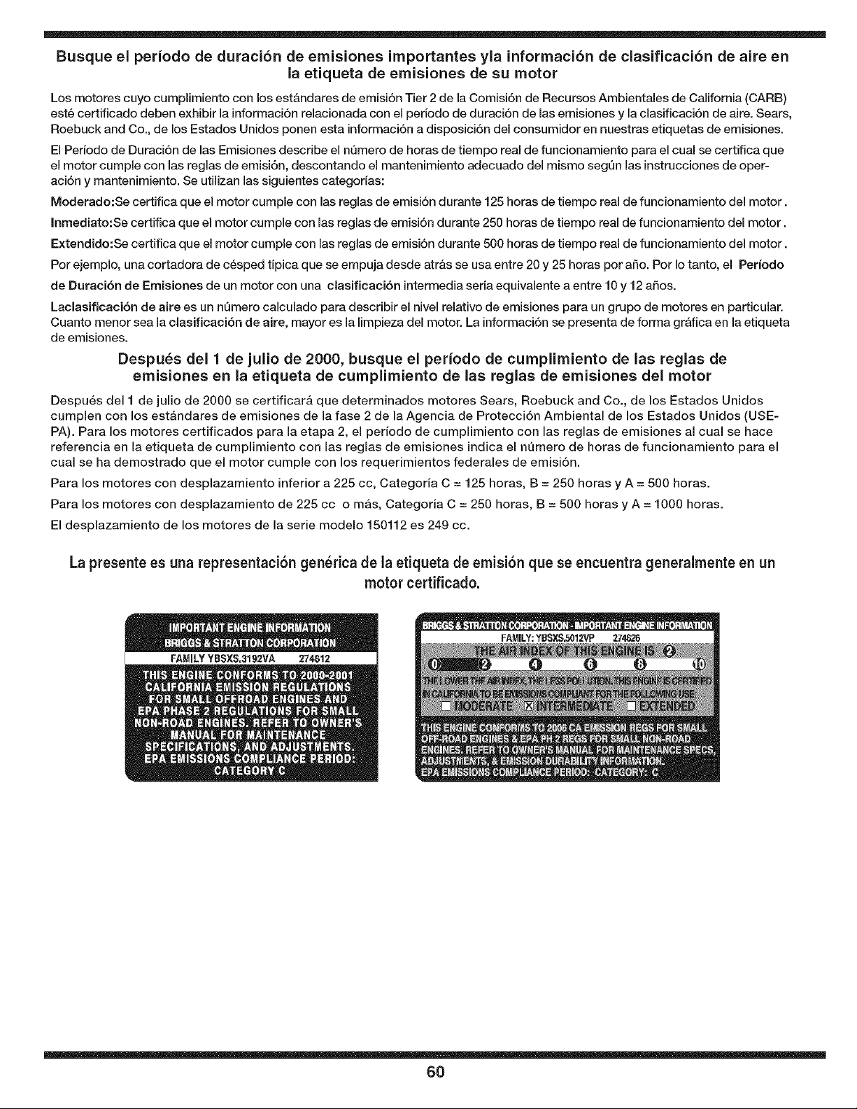
Busque el periodo de duracion de emisiones importantes yla informaci6n de clasificacion de aire en
la etiqueta de emisiones de su motor
Los motores cuyo cumplimiento con los est&ndares de emisi6n Tier 2 de la Comisi6n de Recursos Ambientales de California (CARB)
est6 certificado deben exhibir la informaci6n relacionada con el periodo de duraci6n de las emisiones y la clasificaci6n de aire. Sears,
Roebuck and Co., de los Estados Unidos ponen esta informaci6n a disposici6n del consumidor en nuestras etiquetas de emisiones.
El Pedodo de Duraci6n de las Emisiones describe el nQmero de horas de tiempo real de funcionamiento para el cual se certifica que
el motor cumple con las reglas de emisi6n, descontando el mantenimiento adecuado del mismo segQn las instrucciones de oper-
aci6n y mantenimiento. Se utilizan las siguientes categodas:
Moderado:Se certifica que el motor cumple con las reglas de emisi6n durante 125 horas de tiempo real de funcionamiento del motor.
Inmediato:Se certifica que el motor cumple con las reglas de emisi6n durante 250 horas de tiempo real de funcionamiento del motor.
Extendido:Se certifica que el motor cumple con las reglas de emisi6n durante 500 horas de tiempo real de funcionamiento del motor.
Por ejemplo, una cortadora de c6sped tipica que se empuja desde atr&s se usa entre 20 y 25 horas por afio. Por Io tanto, el Per{odo
de Duraci6n de Emisiones de un motor con una clasificaci6n intermedia seria equivalente a entre 10 y 12 afios.
Laclasificaci6n de aire es un nQmero calculado para describir el nivel relativo de emisiones para un grupo de motores en particular.
Cuanto menor sea la clasificaci6n de aire, mayor es la limpieza del motor. La informaci6n se presenta de forma gr&fica en la etiqueta
de emisiones.
Despu_s del 1 de julio de 2000, busque el per{odo de cumplimiento de las reglas de
emisiones en la etiqueta de cumplimiento de las reglas de emisiones del motor
Despu6s del I de julio de 2000 se certificar& que determinados motores Sears, Roebuck and Co., de los Estados Unidos
cumplen con los est&ndares de emisiones de la fase 2 de la Agencia de Protecci6n Ambiental de los Estados Unidos (USE-
PA). Para los motores certificados para la etapa 2, el periodo de cumplimiento con las reglas de emisiones al cual se hace
referencia en la etiqueta de cumplimiento con las reglas de emisiones indica el n_mero de horas de funcionamiento para el
cual se ha demostrado que el motor cumple con los requerimientos federales de emisi6n.
Para los motores con desplazamiento inferior a 225 cc, Categoria C = 125 horas, B = 250 horas y A = 500 horas.
Para los motores con desplazamiento de 225 cc o re&s, Categoria C = 250 horas, B = 500 horas y A = 1000 horas.
El desplazamiento de los motores de la serie modelo 150112 es 249 cc.
La presente es una representaci6n gen_rica de la etiqueta de emisi6n que se encuentra generalmenteen un
motor certificado.
6O

61

62

63

Your Home
For repair - in your home - of all major brand appliances,
lawn and garden equipment, or heating and cooling systems,
no matter who made it, no matter who sold it!
For the replacement parts, accessories and
owner's manuals that you need to do-it-yourself.
For Sears professional installation of home appliances
and items like garage door openers and water heaters.
1-800-4-MY-HOME ® (1-800-469-4663)
Call anytime, day or night (U.S.A. and Canada)
www.sears.com www.sears.ca
For expert home solutions advice: www.managemyhome.com
Our Home
For repair of carry-in items like vacuums, lawn equipment,
and electronics, call or go on-line for the location of your nearest
Sears Parts & Repair Service Center
1-800-488-1222 (U.S.A.) 1-800-469-4663 (Canada)
Call anytime, day or night
www.sears.com www.sears.ca
To purchase a protection agreement on a product serviced by Sears:
1-800-827-6655 (U.S.A.) 1-800-361-6665 (Canada)
Para pedir servicio de reparaci6n Au Canada pour service en fran(_ais:
a domicilio, y para ordenar piezas: 1-800-LE-FOYER M°
1-888-SU-HOGAR ® (1-800-533-6937)
(1-888-784-6427) www.sears.ca
TM
® Registered Trademark / Trademark / sM Service Mark of Sears Brands, LLC
Tm
® Mama Registrada / ' Mama de F_brica / sM Marca de Servicio de Sears Brands, LLC
MC MD
Marque de commerce / _ Marque d_pos_e de Sears Brands, LLC © Sears Brands, LLC