Operator's Manual
CRRFTSMRN
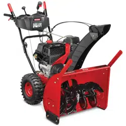
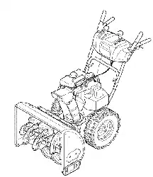
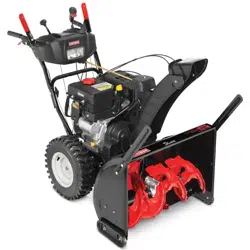
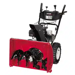
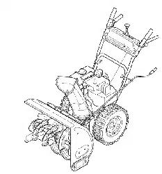
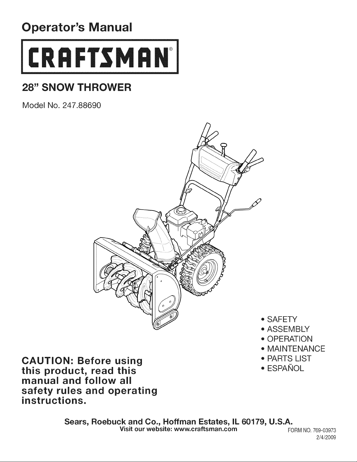
28" SNOW THROWER
Model No. 247.88690
CAUTION: Before using
this product, read this
manual and follow all
safety rules and operating
instructions.
o SAFETY
ASSEMBLY
OPERATION
MAINTENANCE
PARTS LIST
o ESPANOL
Sears, Roebuck and Co., Hoffman Estates, IL 60179, U.S.A.
Visit our website: www.craftsman.com FORMNO.769-03973
2/4/2009
WarrantyStatement.................... Page2
SafeOperationPractices.............. Pages3-6
SafetyLabels......................... Page7
Assembly......................... Pages8-11
Operation........................ Pages12-15
Service&Maintenance.............. Pages16-23
Off-SeasonStorage................... Page24
Troubleshooting...................... Page25
PartsList......................... Pages26-38
RepairProtectionAgreement............ Page42
Espa_ol............................. Page43
CRAFTSMAN LiMiTED WARRANTY
Two Years on Snow Thrower
Whenoperatedand maintainedaccordingto allsuppliedinstructions,ifthis snowthrowerfailsdueto a defectinmaterialorworkmanshipwithin
twoyearsfromthe dateor purchase,call 1-800-4-MY-HOME®to arrangefor free repair.
Thiswarrantyappliesfor only90 days fromthe dateof purchaseif this snow throweris everusedfor commercialor rentalpurposes.
Duringthe first yearof purchase,there willbe no chargefor warrantyserviceinyourhome.Foryourconvenience,in-homewarrantyservicewill
stillbeavailableafter the firstyearof purchase,but a trip chargewill apply.Thischargewill be waivedif youtransportthe snowthrowerto an
authorizedCraftsmandrop-off location.Forthe nearestauthorizedlocation,call 1-800-4-MY-HOME®.
Thiswarranty coversONLYdefects in material andworkmanship. Sears will NOTpay for:
• Expendableitemsthatbecomewornduringnormaluse,includingbutnot limitedto skid shoes,shaveplate,shearpins,sparkplug,air
cleaner,belts,andoil filter.
• Standardmaintenanceservicing,oilchanges,or tune-ups.
Tire replacementor repaircausedby puncturesfrom outsideobjects,suchas nails,thorns,stumps,or glass.
Tireor wheelreplacementor repairresultingfrom normalwear,accident,orimproperoperationor maintenance.
Repairsnecessarybecauseof operatorabuse,includingbutnot limitedto damagecausedby impactingobjectsthat bendthe frameor
crankshaft,orover-speedingtheengine.
• Repairsnecessarybecauseof operatornegligence,includingbut not limitedto,electricaland mechanicaldamagecausedby improper
storage,failureto usethe propergradeandamountof engineoil, or failureto maintainthe equipmentaccordingto the instructionscontained
inthe operator'smanual.
• Engine(fuelsystem)cleaningor repairscausedbyfuel determinedto be contaminatedor oxidized(stale).In general,fuel shouldbeused
within30 daysof itspurchasedate.
Normaldeteriorationandwearof the exteriorfinishes,or productlabel replacement.
Thiswarrantyappliesonly whilethisproductis usedinthe UnitedStates.
Thiswarrantygivesyou specificlegal rights,andyou mayalso haveotherrightswhichvaryfromstateto state.
Sears, Roebuck and Co., Hoffman Estates, IL 60179
EngineOilType: SAE5W-30
EngineOilCapacity: 20ounces
FuelCapacity: 3 Quarts
SparkPlug: Champion®RC12YC
SparkPlugGap: .030"
Model Number.................................................................
Serial Number .................................................................
Dateof Purchase.............................................................
Recordthe modelnumber,serialnumber
anddateof purchaseabove
© Sears Brands,LLC
2
Thissymbolpointsout importantsafetyinstructionswhich,if not
followed,couldendangerthepersonalsafetyand/orpropertyof
yourselfand others. Readandfollowall instructionsin this manual
beforeattemptingto operatethismachine.Failureto complywith
theseinstructionsmay resultin personalinjury.Whenyou seethis
symbol,HEEDITSWARNING!
CALIFORNIA PROPOSiTiON 65
EngineExhaust,someof itsconstituents,andcertainvehicle
componentscontainoremitchemicalsknownto Stateof California
to causecancerandbirthdefectsorotherreproductiveharm,
Thismachinewasbuiltto beoperatedaccordingto the safeopera-
tion practicesin this manual.As with any type of powerequipment,
carelessnessor erroronthe partof the operatorcan result in serious
injury.Thismachineis capableof amputatingfingers,hands,toes
andfeetandthrowingdebris.Failureto observethe followingsafety
instructionscould resultin seriousinjuryor death.
Your Responsibility--Restrict the useof this powermachineto
personswho read,understandandfollowthewarningsand instruc-
tionsin this manualandon the machine,
SAVE THESE INSTRUCTIONS!
TRAiNiNG
• Read,understand,and followall instructionson the machineand
in themanual(s)beforeattemptingto assembleand operate.
Keepthis manualina safe placefor futureand regularreference
andfor orderingreplacementparts.
• Readthe Operator'sManualand followall warningsand safety
instructions.Failureto do so can resultin seriousinjuryto the
operatorand/orbystanders.Forquestionscall, 1-800-659-5917.
Befamiliarwithall controlsandtheir properoperation.Knowhow
to stopthe machineanddisengagethemquickly.
• Neverallowchildrenunder14yearsof ageto operatethis
machine.Children14andover shouldreadandunderstandthe
instructionsand safe operationpracticesin this manualandon
the machineandbe trainedandsupervisedby an adult.
Neverallowadultsto operatethis machinewithoutproper
instruction.
• Thrownobjectscan causeseriouspersonalinjury. Planyour
snow-throwingpatternto avoiddischargeof materialtoward
roads,bystandersandthe like.
Keepbystanders,pets and childrenat least75feetfromthe
machinewhile it is in operation.Stopmachineif anyoneenters
the area.
• Exercisecautionto avoidslippingor falling,especiallywhen
operatingin reverse.
PREPARATION
Thoroughlyinspecttheareawherethe equipmentisto be used.
Removeall doormats,newspapers,sleds,boards,wiresandother
foreignobjects,whichcouldbe trippedoverorthrownby the auger/
impeller.
• Alwayswear safetyglassesor eyeshieldsduringoperationand
while performingan adjustmentor repairto protectyoureyes.
Thrownobjectswhichricochetcancauseseriousinjuryto the
eyes.
Donot operatewithoutwearingadequatewinteroutergarments.
Donot wearjewelry,long scarvesor otherlooseclothing,which
could becomeentangledin movingparts.Wearfootwearwhich
will improvefootingonslipperysurfaces.
Usea groundedthree-wireextensioncordand receptaclefor all
machineswith electricstartengines.
Adjustcollectorhousingheightto cleargravelorcrushedrock
surfaces.
Disengageall controlleversbeforestartingthe engine.
• Neverattemptto make anyadjustmentswhileengineis running,
exceptwherespecificallyrecommendedinthe operator'smanual.
Letengineandmachineadjustto outdoortemperaturebefore
startingto clearsnow.
3
Safe Handling of Gasoline
Toavoidpersonalinjuryor propertydamageuseextremecare in
handlinggasoline.Gasolineis extremelyflammableandthe vaporsare
explosive.Seriouspersonalinjurycan occurwhengasolineis spilled
onyourselfor yourclotheswhichcan ignite.Washyour skin and
changeclothesimmediately.
• Useonly an approvedgasolinecontainer.
• Extinguishall cigarettes,cigars,pipesandother sources
of ignition.
• Neverfuelmachineindoors.
• Neverremovegas capor addfuel whilethe engineis hot
or running.
• Allowengineto coolat leasttwo minutesbeforerefueling.
• Neveroverfill fueltank. Filltank to no morethan1/2inch
belowbottomof filler neckto providespacefor fuel
expansion.
• Replacegasolinecap andtightensecurely.
• If gasolineis spilled,wipeit off the engineand equipment.
Movemachineto anotherarea.Wait5 minutesbefore
startingthe engine.
• Neverstorethe machineor fuel containerinsidewhere
thereis anopenflame,sparkor pilotlight (e.g.furnace,
waterheater,spaceheater,clothesdryer etc.).
• Allowmachineto cool at least5 minutesbeforestoring.
• Neverfill containersinsidea vehicleor ona truckor trailer
bedwitha plasticliner.Alwaysplacecontainersonthe
groundawayfromyourvehiclebeforefilling.
• If possible,removegas-poweredequipmentfrom thetruck
ortrailerand refuelit on the ground.If this is not possible,
then refuelsuch equipmenton a trailerwitha portable
container,ratherthan fromagasolinedispensernozzle.
• Keepthe nozzlein contactwith the rimof the fueltank or
containeropeningat alltimesuntil fuelingis complete.Do
notuse a nozzlelock-opendevice.
OPERATION
• Do not puthandsorfeetnear rotatingparts,in the auger/impeller
housingor chuteassembly.Contactwith the rotatingpartscan
amputatehandsandfeet.
• Theauger/impellercontrolleveris a safetydevice.Neverbypass
itsoperation.Doingso makesthe machineunsafeand maycause
personalinjury.
• Thecontrol leversmustoperateeasilyin bothdirectionsand
automaticallyreturnto the disengagedpositionwhenreleased.
• Neveroperatewith a missingor damagedchuteassembly.Keep
all safetydevicesin placeand working.
• Neverrunan engine indoorsor in a poorlyventilatedarea. Engine
exhaustcontainscarbonmonoxide,an odorlessanddeadlygas.
• Do notoperatemachinewhileunder the influenceof alcoholor
drugs.
• Mufflerand engine becomehotand can causea burn.Do not
touch.Keepchildrenaway.
• Exerciseextremecautionwhenoperatingon or crossinggravel
surfaces.Stay alertfor hidden hazardsor traffic.
• Exercisecautionwhenchangingdirectionand whileoperatingon
slopes.
• Planyoursnow-throwingpatternto avoiddischargetowards
windows,walls,carsetc. Thus,avoidingpossibleproperty
damageor personalinjurycausedby a ricochet.
• Neverdirect dischargeat children,bystandersand petsor allow
anyoneinfrontof the machine.
• Donot overloadmachinecapacityby attemptingto clearsnowat
too fastof a rate.
• Neveroperatethis machinewithoutgoodvisibility or light. Always
be sureof yourfootingand keepa firmholdon the handles.Walk,
neverrun.
• Disengagepowerto theauger/impellerwhentransportingor not
in use.
• Neveroperatemachineat high transportspeedson slippery
surfaces.Lookdownand behindand usecare whenbackingup.
• If the machineshouldstart to vibrateabnormally,stopthe engine,
disconnectthe sparkplugwire andgroundit againstthe engine.
Inspectthoroughlyfor damage.Repairanydamagebefore
startingandoperating.
• Disengageall controlleversandstopenginebeforeyouleave
the operatingposition(behindthe handles).Wait untilthe auger/
impellercomesto a completestop beforeuncloggingthechute
assembly,makingany adjustments,or inspections.
• Neverput yourhand in the dischargeor collectoropenings.
Alwaysusethe clean-outtool providedto unclogthedischarge
opening.Donot unclogchuteassemblywhileengineis running.
Shutoff engineand remainbehindhandlesuntilall movingparts
havestoppedbeforeunclogging.
• Useonly attachmentsand accessoriesapprovedby the manufac-
turer (e.g.wheelweights,tire chains,cabsetc.).
• Whenstartingengine,pullcord slowlyuntilresistanceis felt, then
pull rapidly.Rapidretractionof startercord(kickback)will pull
handandarmtowardenginefasterthan youcan let go. Broken
bones,fractures,bruisesor sprainscould result.
• If situationsoccur whichare notcoveredinthis manual,use care
andgoodjudgment.ContactCustomerSupportfor assistance
andthe nameof your nearestservicingdealer.
4
MAINTENANCE & STORAGE
• Nevertamperwithsafetydevices.Checktheirproperoperation
regularly.Referto the maintenanceandadjustmentsectionsof
thismanual.
• Beforecleaning,repairing,or inspectingmachinedisengageall
controlleversandstopthe engine.Wait untilthe auger/impeller
cometo a completestop.Disconnectthe sparkplug wireand
groundagainsttheengineto preventunintendedstarting.
Checkboltsand screwsfor propertightnessat frequentintervals
to keepthe machineinsafeworkingcondition.Also, visually
inspectmachinefor anydamage.
Do notchangetheenginegovernorsettingor over-speedthe
engine.Thegovernorcontrolsthe maximumsafeoperatingspeed
of the engine.
Snowthrowershaveplatesand skid shoesaresubjectto wear
anddamage.Foryoursafetyprotection,frequentlycheckall
componentsand replacewithoriginalequipmentmanufacturer's
(OEM)partsonly."Useof partswhichdo not meetthe original
equipmentspecificationsmayleadto improperperformanceand
compromisesafety!"
Checkcontrolleversperiodicallyto verifytheyengageanddisen-
gageproperlyand adjust,if necessary.Referto the adjustment
sectioninthisoperator'smanualfor instructions.
Maintainor replacesafetyand instructionlabels,as necessary.
• Observeproperdisposallawsand regulationsfor gas, oil,etc. to
protectthe environment.
Priorto storing,run machinea few minutestoclear snowfrom
machineand preventfreezeup of auger/impeller.
Neverstorethe machineorfuel containerinsidewherethereisan
openflame,spark or pilot lightsuch as a waterheater,furnace,
clothesdryer etc.
Alwaysreferto the operator'smanualfor properinstructionson
off-seasonstorage.
Checkfuelline,tank, cap,andfittingsfrequentlyfor cracksor
leaks.Replaceif necessary.
Do notcrankenginewithsparkplugremoved.
Accordingto the ConsumerProductsSafetyCommission(CPSC)
andthe U.S.EnvironmentalProtectionAgency(EPA),thisproduct
hasan AverageUsefulLifeof seven(7) years,or 60 hoursof
operation.At the endof theAverageUsefulLifehavethe machine
inspectedannuallybyan authorizedservicedealerto ensurethat
allmechanicaland safetysystemsare workingproperlyand not
wornexcessively.Failureto do so can resultin accidents,injuries
ordeath.
DO NOT MODIFY ENGINE
Toavoidseriousinjuryor death,do not modifyengine in any way.
Tamperingwiththe governorsettingcanlead to a runawayengineand
causeit to operateat unsafespeeds.Nevertamperwithfactorysetting
of enginegovernor.
NOTICE REGARDING EMISSIONS
Engineswhich are certifiedtocomplywithCaliforniaandfederal
EPAemissionregulationsfor SORE(SmallOff RoadEquipment)are
certifiedto operateon regularunleadedgasoline,and mayinclude
the followingemissioncontrol systems:EngineModification(EM),
OxidizingCatalyst(OC), SecondaryAir Injection(SAI)and ThreeWay
Catalyst(TWO)if so equipped.
SPARK ARRESTOR
Thismachineisequippedwithaninternalcombustionengineand
shouldnotbe usedon or nearany unimprovedforest-covered,
brush-coveredorgrass-coveredlandunlessthe engine'sexhaust
systemisequippedwith a sparkarrestermeetingapplicablelocalor
statelaws(if any)
Ifa sparkattester is used, it shouldbe maintainedin effectiveworking
orderby theoperator.Inthe Stateof Californiathe aboveis required
bylaw (Section4442of the CaliforniaPublicResourcesCode).Other
statesmayhavesimilarlaws. Federallawsapplyon federallands.
A spark arresterfor the muffleris availablethroughyournearestSears
PartsandRepairServiceCenter.
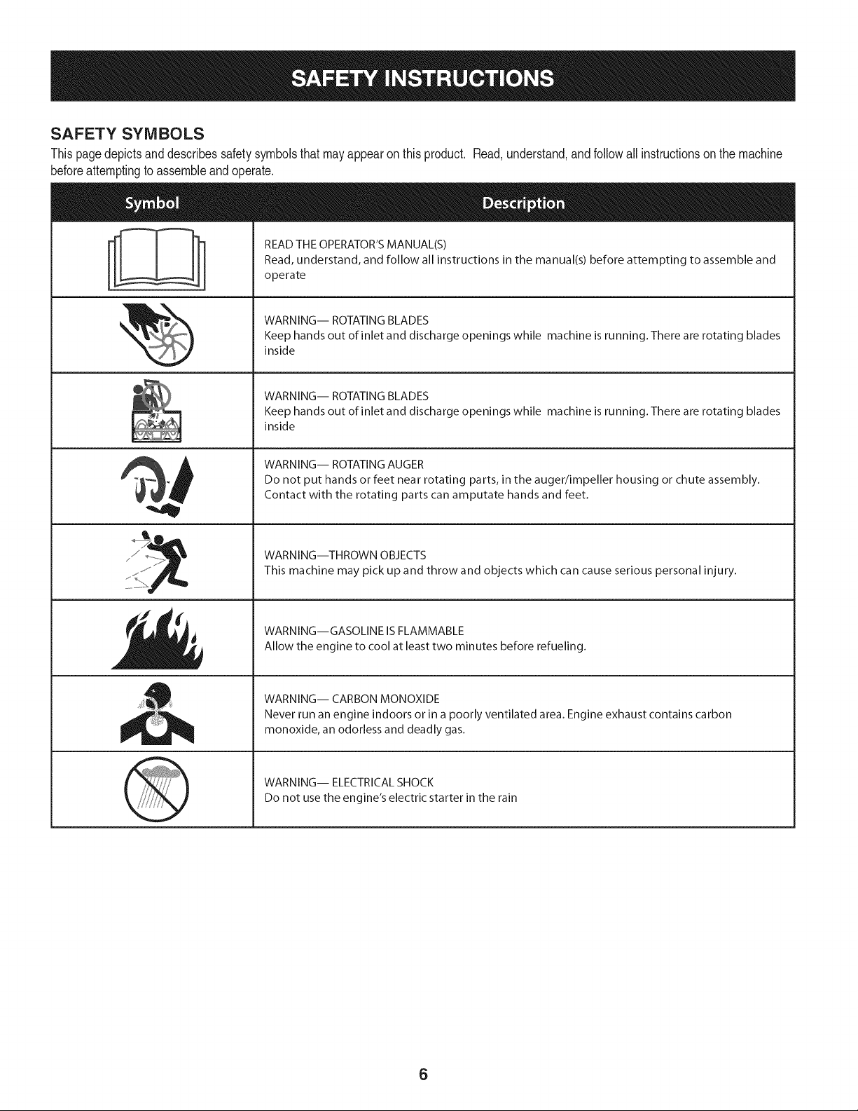
SAFETY SYMBOLS
Thispagedepictsanddescribessafetysymbolsthatmayappearonthisproduct. Read,understand,and followall instructionson the machine
beforeattemptingto assembleandoperate.
i
i
READ THE OPERATOR'S MANUAL(S)
Read, understand, and follow all instructions in the manual(s) before attempting to assemble and
operate
WARNING-- ROTATING BLADES
Keep hands out of inlet and discharge openings while machine is running. There are rotating blades
inside
WARNING-- ROTATING BLADES
Keep hands out of inlet and discharge openings while machine is running. There are rotating blades
inside
WARNING-- ROTATING AUGER
Do not put hands or feet near rotating parts, in the auger/impeller housing or chute assembly.
Contact with the rotating parts can amputate hands and feet.
WARNING--THROWN OBJECTS
This machine may pick up and throw and objects which can cause serious personal injury.
WARNING--GASOLINE IS FLAMMABLE
Allow the engine to cool at least two minutes before refueling.
WARNING-- CARBON MONOXIDE
Never run an engine indoors or in a poorly ventilated area. Engine exhaust contains carbon
monoxide, an odorless and deadly gas.
WARNING-- ELECTRICAL SHOCK
Do not use the engine's electric starter in the rain
6
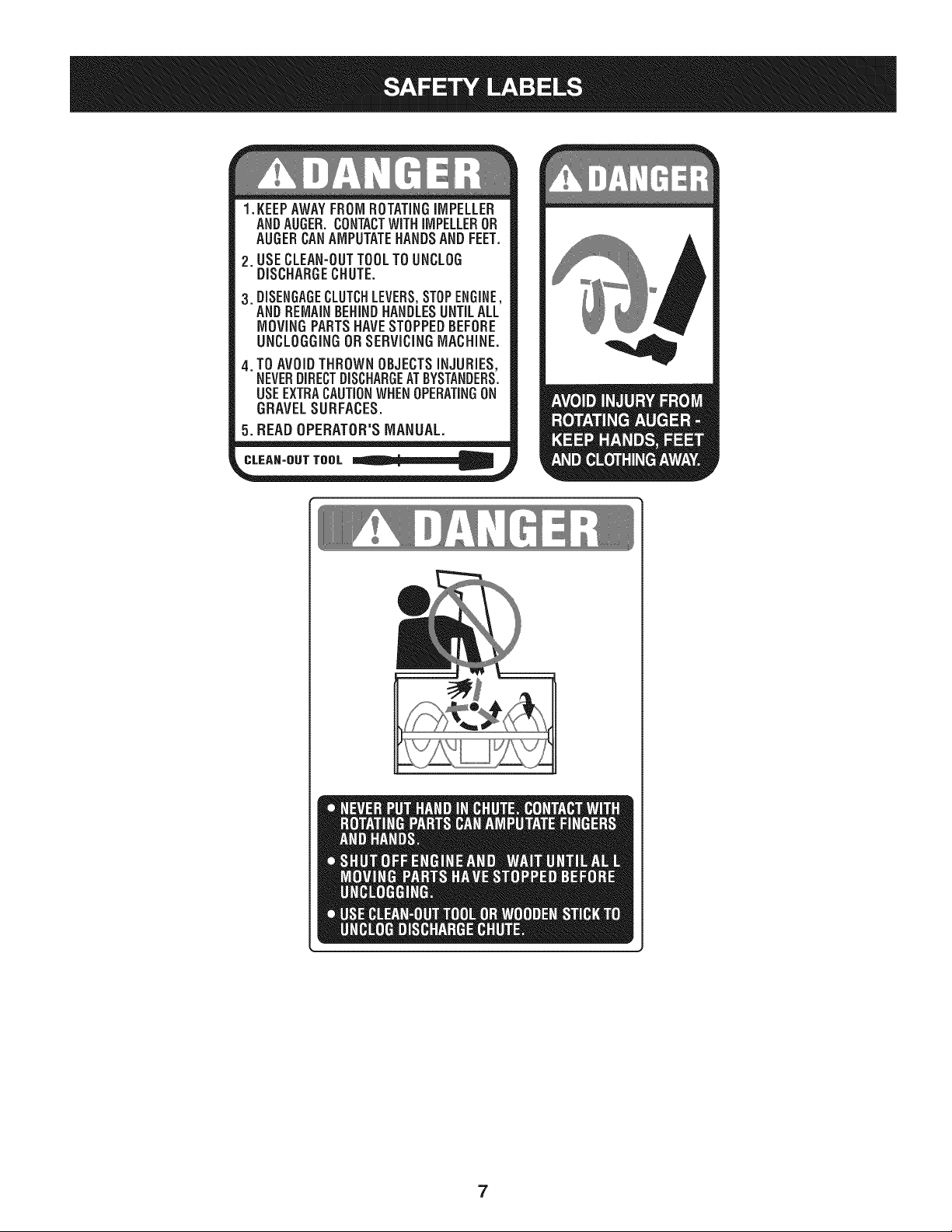
1.KEEPAWAYFROMROTATINGiMPELLER
ANDAUGER,CONTACTWiTHiMPELLEROR
AUGERCANAMPUTATEHANDSANDFEET.
2. USECLEAN-OUTTOOLTOUNCLOG
DISCHARGECHUTE.
3.DISENGAGECLUTCHLEVERS,STOPENGINE,
AND REMAINBEHINDHANDLESUNTILALL
MOVING PARTSHAVE STOPPEDBEFORE
UNCLOGGING OR SERViCiNGMACHINE.
TO AVOIDTHROWN OBJECTSiNJURiES,
NEVERDIRECTDISCHARGEATBYSTANDERS.
USEEXTRACAUTIONWHEN OPERATINGON
GRAVEL SURFACES.
5.BEAD OPERATOR'S MANUAL.
CLEAN-OUT TOOL
7
NOTE:Referencesto rightorleft sideof the snowthrowerare
determinedfrombehindthe unit inthe operatingposition(standing
directlybehindthe snowthrower,facingthe handlepanel).
REMOVING FROM CARTON
1. Cut the cornersof thecarton and lay the sidesflat on the ground.
Removeand discard all packinginserts.
2. Movethe snowthrowerout of thecarton.
3. Makecertainthe carton has beencompletelyemptiedbefore
discardingit.
LOOSE PARTS
Tworeplacementaugershearpinsare includedwith this manual.Refer
to ReplacingShearPinsinthe Operationsectionfor moreinformation
regardingshearpin replacement.
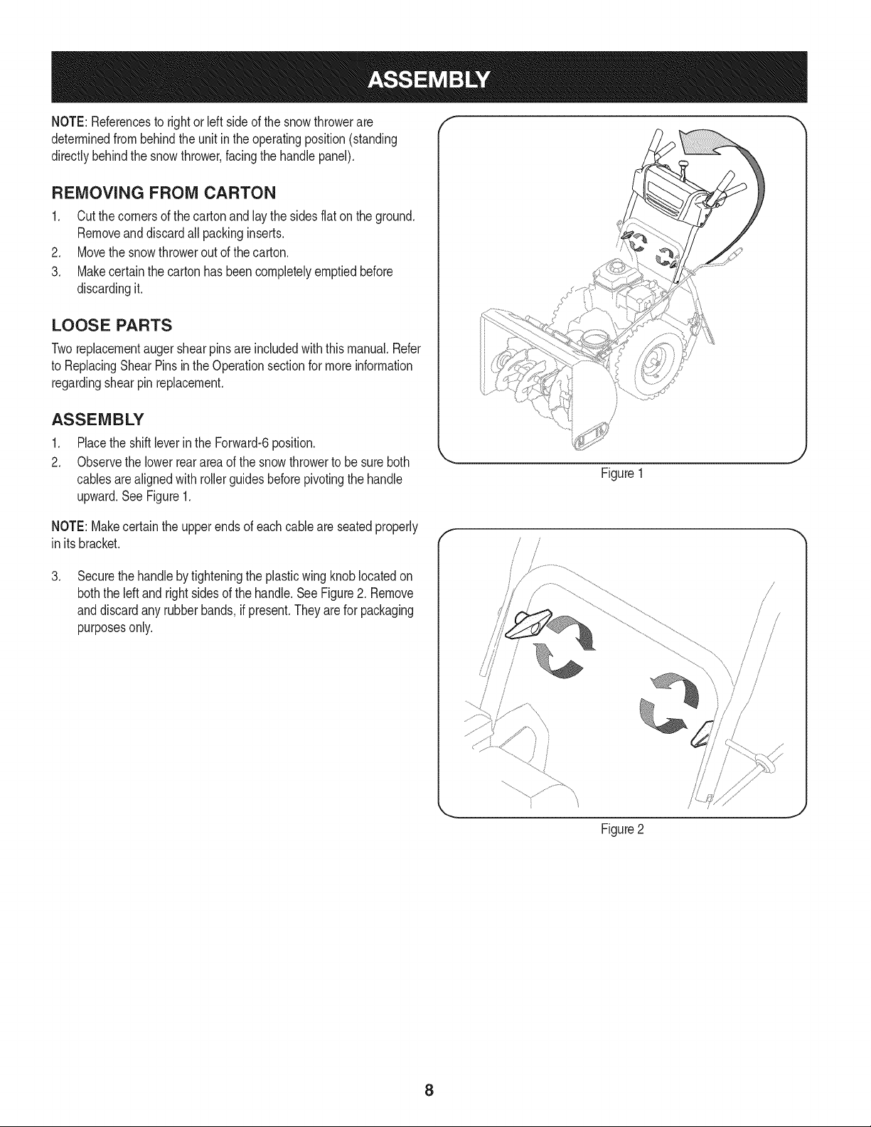
ASSEMBLY
1. Placethe shiftleverin the Forward-6position.
2. Observethe lowerreararea of the snowthrowerto be sure both
cablesarealignedwith rollerguidesbeforepivotingthe handle
upward.See Figure1.
Figure1
NOTE:Makecertainthe upperends of eachcableare seatedproperly
in its bracket.
.
Securethehandlebytighteningthe plasticwing knoblocatedon
boththe left and rightsides of the handle.SeeFigure2. Remove
anddiscardany rubberbands,if present.They are for packaging
purposesonly.
f
!
/
/
/
Figure2
8
.
5.
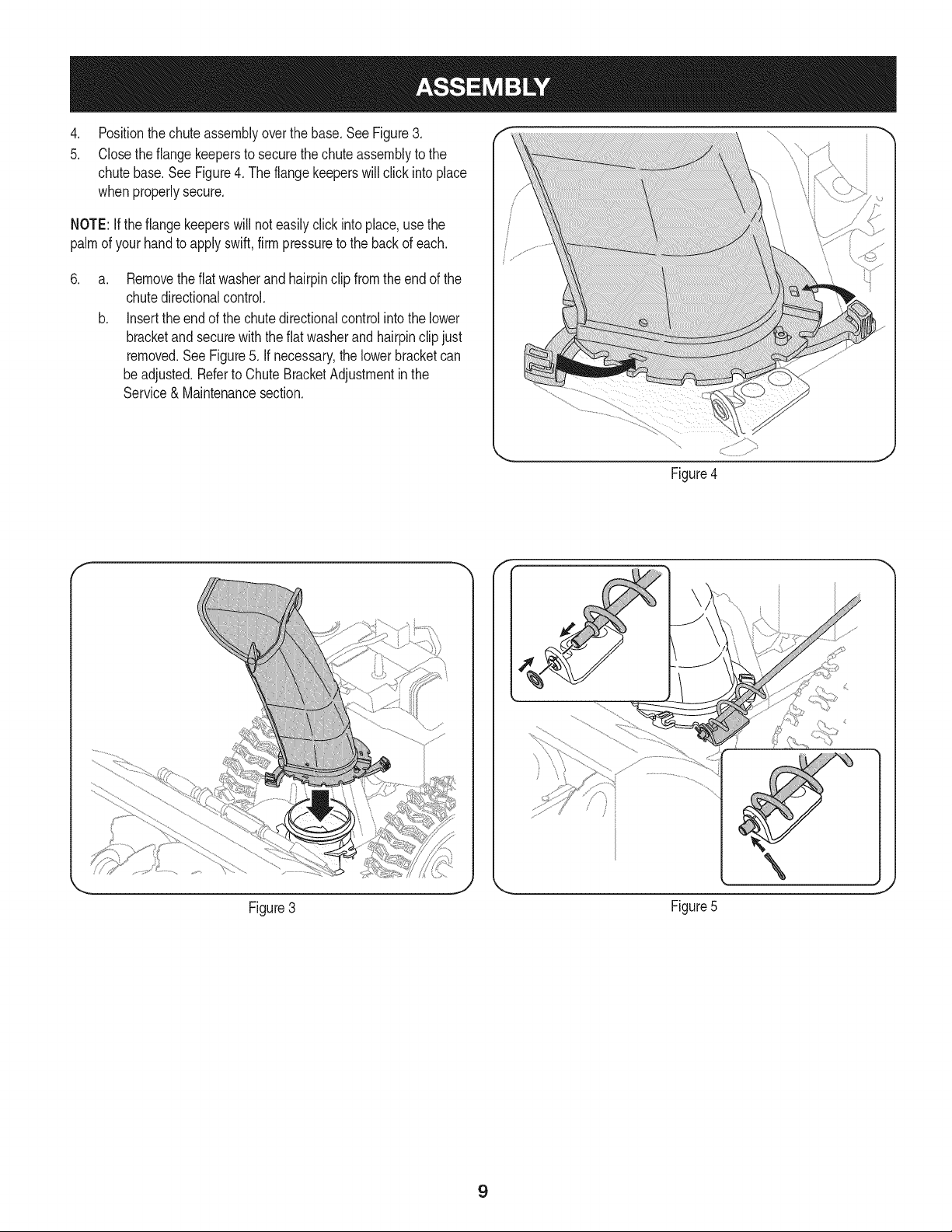
Positionthechuteassemblyoverthe base.See Figure3.
Closethe flangekeepersto securethechuteassemblyto the
chutebase.SeeFigure4. The flangekeeperswill click intoplace
whenproperlysecure.
NOTE:Ifthe flangekeeperswill noteasilyclickinto place,usethe
palmof yourhandto applyswift,firmpressureto the backof each.
.
a.
b.
Removetheflat washerand hairpinclip fromthe endof the
chutedirectionalcontrol.
Insertthe endof the chutedirectionalcontrolinto the lower
bracketand securewith the flat washerandhairpinclipjust
removed.See Figure5. If necessary,the lowerbracketcan
beadjusted.Referto ChuteBracketAdjustmentinthe
Service& Maintenancesection.
Figure4
f F
Figure3
\
J
Figure5
9
SET-UP
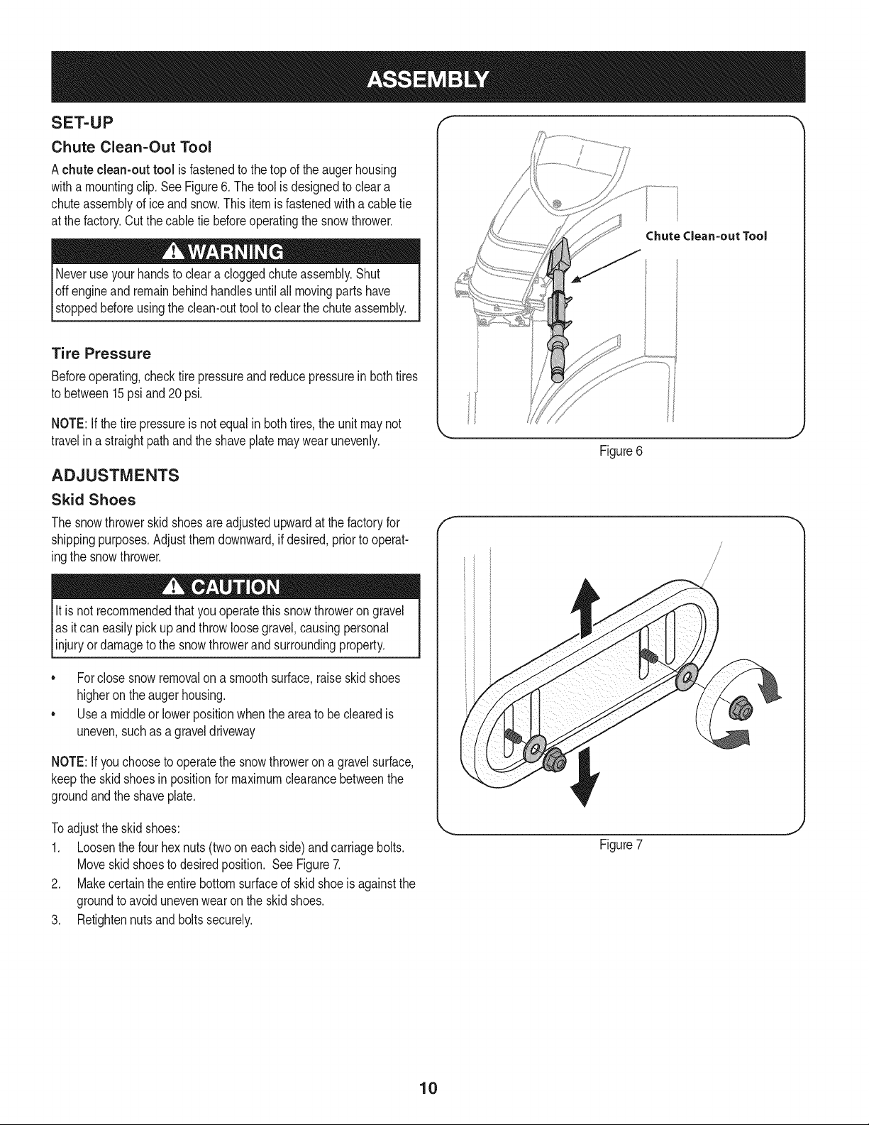
Chute Clean-Out Tool
Achute clean-out tool is fastenedto the top of the augerhousing
witha mountingclip. See Figure6. The tool is designedto cleara
chuteassemblyof ice andsnow.This item is fastenedwitha cabletie
at the factory.Cut thecable tie beforeoperatingthe snowthrower.
loft _1 .allmovingpartshave
stoppedbeforeusingthe clean-outtool to clearthe chuteassembly.
Tire Pressure
Beforeoperating,checktire pressureand reducepressurein bothtires
to between15psiand20 psi.
NOTE:If thetire pressureis notequal in bothtires,the unit maynot
travelin a straightpathand the shaveplatemay wearunevenly.
ADJUSTMENTS
Skid Shoes
The snowthrowerskidshoesareadjustedupwardat thefactoryfor
shippingpurposes.Adjustthemdownward,if desired,priorto operat-
ingthe snowthrower.
It is not recommendedthatyouoperatethis snowthrowerongravel
as it can easilypickup and throwloosegravel,causingpersonal
njuryordamageto the snowthrowerand surroundng property.
• Forclosesnowremovalona smoothsurface,raiseskidshoes
higheronthe augerhousing.
• Usea middleor lowerpositionwhentheareato be clearedis
uneven,suchas a graveldriveway
NOTE:If youchooseto operatethe snowthrowerona gravelsurface,
keepthe skid shoesin positionfor maximumclearancebetweenthe
groundandthe shaveplate.
f
ChuteClean-outTool
Figure6
/
Toadjustthe skid shoes:
1. Loosenthe four hexnuts(twooneach side)and carriagebolts.
Moveskidshoesto desiredposition. See Figure7.
2. Makecertainthe entirebottomsurfaceof skidshoeis againstthe
groundto avoidunevenwearonthe skidshoes.
3. Retightennutsand boltssecurely.
Figure7
10
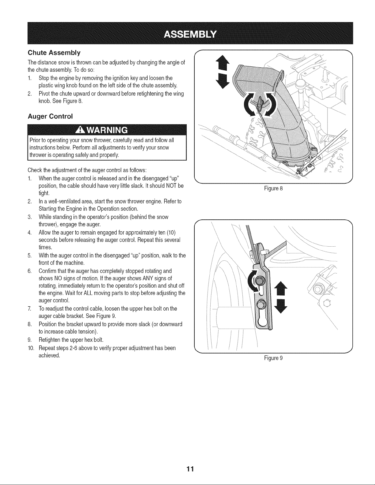
Chute Assembly
Thedistancesnowis throwncan be adjustedby changingthe angleof
the chuteassembly.Todo so:
1. Stopthe engineby removingthe ignitionkeyand loosenthe
plasticwingknobfoundon the left sideof the chuteassembly.
2. Pivotthe chute upwardordownwardbeforeretighteningthewing
knob.See Figure8.
Auger Control
Priorto operatingyour snowthrower,carefullyreadandfollowall
instructionsbelow. Performall adjustmentsto verifyyour snow
throweris operatingsafelyandproperly.
Checktheadjustmentof the augercontrolas follows:
1. Whentheauger controlis releasedandin the disengaged"up"
position,the cableshouldhavevery little slack. It shouldNOTbe
tight.
2. In a well-ventilatedarea,start the snowthrowerengine.Referto
Startingthe Engineinthe Operationsection.
3. Whilestandingin the operator'sposition(behindthe snow
thrower),engagethe auger.
4. Allowtheauger to remainengagedfor approximatelyten (10)
secondsbeforereleasingthe augercontrol.Repeatthis several
times.
5. With theauger controlin thedisengaged"up" position,walkto the
frontof the machine.
6. Confirmthatthe augerhas completelystoppedrotatingand
showsNOsigns of motion.If the augershowsANYsignsof
rotating,immediatelyreturnto the operator'spositionandshutoff
the engine.Waitfor ALL movingparts to stop beforeadjustingthe
augercontrol.
7. Toreadjustthecontrolcable, loosentheupperhexbolt onthe
augercablebracket.See Figure9.
8. Positionthe bracketupwardto providemoreslack(or downward
to increasecabletension).
9. Retightenthe upperhex bolt.
10. Repeatsteps2-6 aboveto verifyproperadjustmenthasbeen
achieved.
Figure8
Figure9
11
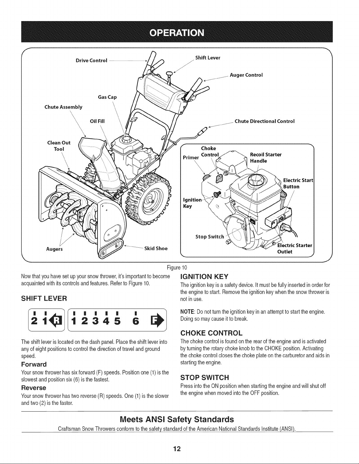
ChuteAssembly
\
\
Clean Out
Tool
'\
\
Gas Cap
Augers _ Skid Shoe
Auger Control
Chute Directional Control
Recoil Starter
Handle
Electric Start
Button
Outlet
Figure10
Nowthat youhaveset up yoursnowthrower,it'simportantto become iGNiTiON KEY
acquaintedwith its controlsandfeatures.Referto Figure10.
SHIFT LEVER
J
The ignitionkeyisa safetydevice.It mustbe fullyinsertedinorderfor
the engineto start. Removethe ignitionkeywhenthe snowthroweris
not inuse.
'
1 2345 6
The shiftleverislocatedon the dash panel.Placethe shift leverinto
anyof eight positionsto controlthe directionof travelandground
speed.
Forward
Yoursnowthrowerhas sixforward(F) speeds.Positionone (1)is the
slowestandpositionsix(6) isthe fastest.
Reverse
Yoursnowthrowerhastwo reverse(R) speeds.One(1)isthe slower
andtwo(2) isthe faster.
NOTE: Donot turnthe ignitionkey inan attemptto startthe engine.
Doingso may causeitto break.
CHOKE CONTROL
The chokecontrolisfoundon the rearof the engineand isactivated
by turningthe rotarychokeknobto the CHOKEposition.Activating
the chokecontrolclosesthe choke plateon thecarburetorand aids in
startingthe engine.
STOP SWITCH
Pressintothe ON positionwhen startingthe engineandwill shutoff
the enginewhenmovedintotheOFFposition.
Meets ANSi Safety Standards
CraftsmanSnowThrowersconformto the safetystandardof the AmericanNationalStandardsInstitute(ANSI).
12
RECOIL STARTER HANDLE
Thishandleis usedto manuallystartthe engine.
ELECTRIC STARTER BUTTON
Pressingthe electricstarterbuttonengagesthe engine'selectric
starterwhenpluggedintoa 120Vpowersource,
ELECTRIC STARTER OUTLET
Requiresthe useof a three-prongoutdoorextensioncord(included)
anda 120Vpowersource/walloutlet.
PRIMER
Depressingthe primerforcesfuel directlyintothe engine'scarburetor
to aidin cold-weatherstarting,
OiL FILL
Engineoil levelcan becheckedand oiladdedthroughtheoil fill.
GAS CAP
Unthreadthe gascap to addgasolineto the fuel tank.
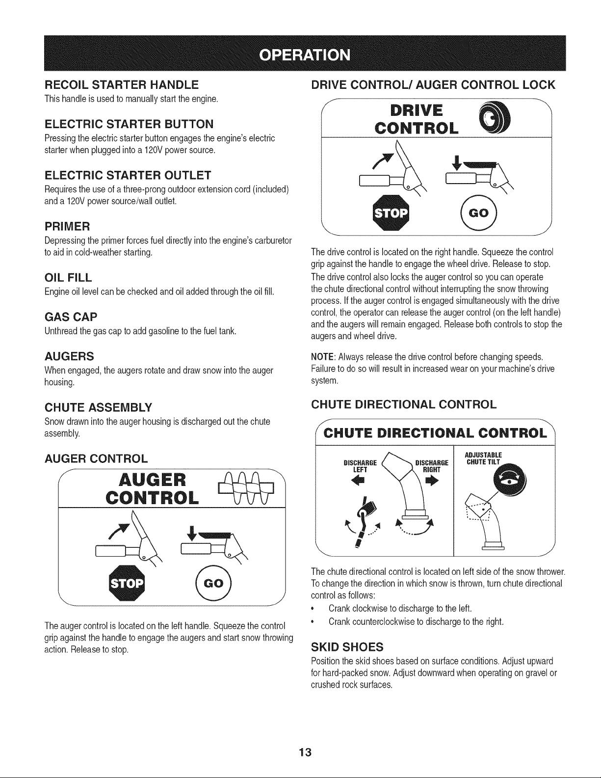
DRIVE CONTROL/AUGER CONTROL LOCK
f
The drivecontrolis locatedon the righthandle.Squeezethe control
gripagainstthe handleto engagethe wheeldrive. Releaseto stop.
The drivecontrolalso lockstheaugercontrolso youcan operate
the chutedirectionalcontrolwithoutinterruptingthe snowthrowing
process,if the augercontrolisengagedsimultaneouslywiththe drive
control,the operatorcan releasethe augercontrol(onthe lefthandle)
andthe augerswill remainengaged.Releaseboth controlsto stopthe
augersand wheeldrive.
AUGERS
Whenengaged,the augersrotateanddrawsnowintothe auger
housing.
NOTE:Alwaysreleasethedrivecontrol beforechangingspeeds.
Failureto do so will result in increasedwearon yourmachine'sdrive
system.
CHUTE ASSEMBLY
Snowdrawninto theaugerhousingis dischargedout the chute
assembly.
AUGER CONTROL
Theaugercontrol is locatedon the left handle.Squeezethecontrol
gripagainstthe handleto engagetheaugersand start snowthrowing
action.Releaseto stop.
CHUTE DIRECTIONAL CONTROL
f -\
CHUTE DiRECTiONAL CONTROL
\
DISCHARGE
LEFT
DISCHARGE
ADJUSTABLE
CHUTETILT
The chutedirectionalcontrolis locatedonleft sideof the snowthrower.
Tochangethe directionin which snowis thrown,turnchutedirectional
controlas follows:
* Crankclockwiseto dischargeto the left.
* Crankcounterclockwiseto dischargeto the right.
SKiD SHOES
Positionthe skidshoesbasedon surfaceconditions.Adjustupward
for hard-packedsnow.Adjustdownwardwhenoperatingon gravelor
crushedrocksurfaces.
13
CLEAN-OUT TOOL
Neveruseyour handsto clearacloggedchuteassembly.Shut
offengineand remainbehindhandlesuntilall movingpartshave
stoppedbeforeusingthe clean-outtool to clearthe chute assembly.
Thechute clean-outtool is convenientlyfastenedto the rearof the
augerhousingwith a mountingclip. Shouldsnowand ice become
lodgedin thechute assemblyduringoperation,proceedas followsto
safelycleanthechute assemblyand chute opening:
1. Releaseboththe AugerControland the DriveControl.
2. Stopthe engineby removingthe ignitionkey.
3. Removethe clean-outtoolfromthe clip whichsecuresit to the
rearof the augerhousing.
4. Use the shovel-shapedendof theclean-outtool to dislodgeand
scoopany snowand icewhich hasformedin andnearthechute
assembly.
5. Refastenthe clean-outtool to the mountingclip on the rear of
theauger housing,reinsertthe ignitionkey and startthe snow
thrower'sengine.
6. Whilestandingin the operator'sposition(behindthesnow
thrower),engagethe auger controlfora fewsecondsto clear any
remainingsnowand ice from thechute assembly.
BEFORE STARTING ENGINE
Read,understand,and followall instructionsand warningson the
machineand in this manualbeforeoperating.
Oil
The unitwasshippedwith oil inthe engine.Checkoil levelbeforeeach
operationto ensureadequateoil in the engine.Forfurtherinstructions,
referto the stepson page 16.
1. Removethe dipstickfromthe oil fill.
2. Checkand makesurethat the levelof oil is upto the FULLmark
onthe dipstick.
3. If the oil levelis not upto FULL,pour fresh motoroil (5W-30,with
a minimumclassificationof SF/SG/SH/SJ)slowlythroughthe
opening.Replaceoil fill dipstickandcheckoil levelagain.
Gasoline
• Storegasolineinaclean,approvedcontainerand keepthecap in
placeon the container.
• Makesurethatthe containerfromwhichyoupourthe gasolineis
cleanand freefrom rust or otherforeignparticles.
Useextremecarewhen handlinggasoline.Gasolineis extremely
flammableand thevaporsare explosive.Neverfuelthe machine
indoorsor whilethe engine is hotor running.Extinguishcigarettes,
cigars,pipesand othersourcesof ignition.
Alwaysfill the fuel tank outdoorsand usea funnelor spoutto
preventspilling.
• Fillfuel tank with clean,fresh,unleadedgasolinewitha minimum
of 85 octane.Freshfuel preventsgumfromforminginthe fuel
systemor on essentialcarburetorparts.Purchasefuelin a
quantitythat can be usedwithin30 days.
• Neverfill the fuel tank completely.Fillthe tankto within1-1/2"
fromthe top to providespacefor expansionof fuel.
• Makesureto wipeoff anyspilledfuel beforestartingthe engine.
STARTING THE ENGINE
1. Makecertainboththe augercontrol anddrivecontrolarein the
disengaged(released)position.
2. Insertignitionkeyinto slot.Makesure it snapsinto place.Do not
attemptto turn the key.
NOTE: Theenginecannotstartwithoutthe keyis fully insertedintothe
ignitionswitch.
Electric Starter
Determinethat yourhome'swiringis a three-wiregroundedsystem.
Aska licensedelectricianif you arenotcertain.
The optionalelectricstarteris equippedwith a groundedthree-wire
powercordand plug,and is designedto operateon 120volt AC
householdcurrent.It mustbe usedwith a properlygroundedthree-
prongreceptacleat all timesto avoidthe possibilityof electricshock.
Followall instructionscarefullyprior to operatingtheelectricstarter.
DONOTuse electricstarterin the rain.
Ifyou havea groundedthree-prongreceptacle,proceedas follows:
1. Plugthe extensioncord intothe outletlocatedon the engine's
surface.Plugthe otherend of extensioncord intoa three-prong
120-volt,grounded,AC outletina well-ventilatedarea.
2. Rotatechokecontrolto CHOKEI Jl position.
3. Ifit is 15°For higherpushprimertwotimes,if below15°F,push
primerfourtimes.
4. PushStopswitchto ON position.
14
5. Pushstarterbuttonto start engine.
To prolongstarterlife, useshort startingcycles(5 secondsmaximum
then waitoneminute).
6. Oncethe enginestarts,releasestarterbutton.
7. Allowtheengine to warmup severalminutes,adjustingchoke
towardRUNposition.Waituntilengineruns smoothlybeforeeach
chokeadjustment.
8. Whendisconnectingthe extensioncord,alwaysunplugthe end
at the three-prongwalloutlet beforeunpluggingthe oppositeend
fromthe snowthrower.
Recoil Starter
1. Rotatechoke controlto CHOKE IJl position.
2. Depressprimer.Ifit is 15°For higherpushprimertwotimes,if
below15°F,pushprimerfourtimes.
3. PushStopswitchto ONposition.
4. Graspthe recoilstarterhandleand slowlypull the ropeout. At
the pointwhereit becomesslightlyharderto pullthe rope,slowly
allowthe ropeto recoil.
5. Pull the starterhandlewith a firm, rapidstroke.Donot release
the handleandallowit to snap back.Keepa firmholdonthe
starterhandleand allowit to slowlyrecoil.
6. Allowtheengine to warmup severalminutes,adjustingchoke
towardRUNposition.Waituntilengineruns smoothlybeforeeach
chokeadjustment.
To avoidunsupervisedengineoperation,neverleavethe machine
unattendedwiththe enginerunning.Turnthe engineoffafter useand
removeignitionkey.
STOPPING THE ENGINE
Afteryouare finishedsnow-throwing,runenginefor a few minutes
beforestoppingto help dry off any moistureonthe engine.
1. PushStopswitchto OFFposition.
2. Removetheignitionkey and store in a safeplace.
3. Wipeall snowandmoisturefrom thearea aroundthe engineas
wellas the areainandaroundthe drivecontroland augercontrol.
Also,engageand releasebothcontrolsseveraltimes.
NOTE:NEVERrepositiontheshift lever(changespeedsor direction
of travel)withoutfirst releasingthe drivecontrolandbringingthe snow
throwerto a completestop.Doingsowill resultin prematurewearto
the snowthrower'sdrivesystem.
TO ENGAGE AUGERS
1. Toengagethe augersand startthrowingsnow,squeezethe
augercontrolagainstthe lefthandle.Releaseto stop theaugers.
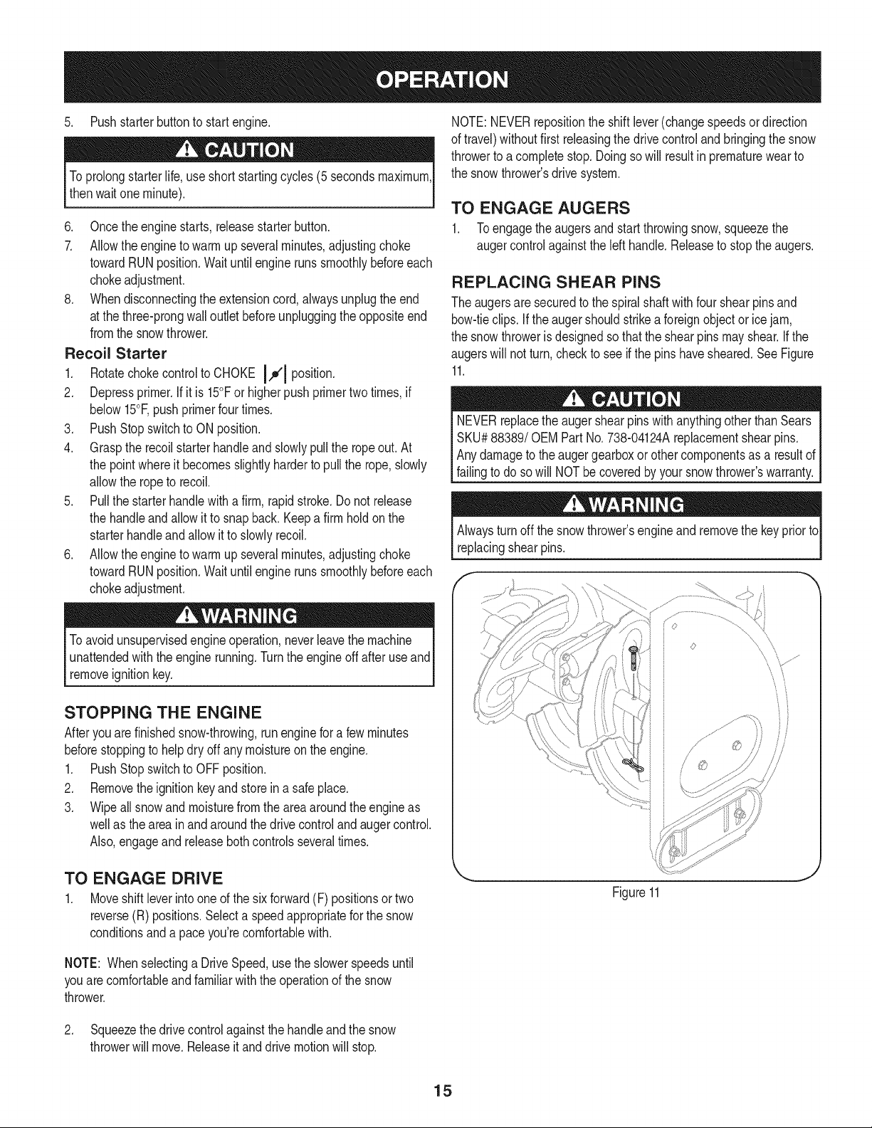
REPLACING SHEAR PINS
The augersare securedto the spiralshaftwithfour shearpinsand
bow-tieclips. Ifthe augershouldstrikea foreignobject or icejam,
the snowthroweris designedsothat the shearpins mayshear.If the
augerswill notturn, checkto see if the pins havesheared.SeeFigure
11.
NEVERreplacethe augershearpinswith anythingotherthan Sears
SKU#88389/OEM PartNo.738-04124Areplacementshearpins.
Anydamageto theauger gearboxorother componentsas a resultof
failingto do sowill NOTbecoveredbyyour snowthrower'swarranty.
Alwaysturn off thesnowthrower'sengineand removethe keypriorto
replacingshearpins.
f
TO ENGAGE DRIVE
1. Moveshift leverintoone of the six forward(F) positionsor two
reverse(R) positions.Selecta speedappropriatefor the snow
conditionsand a paceyou'recomfortablewith.
NOTE: Whenselectinga DriveSpeed,usethe slowerspeedsuntil
youare comfortableand familiarwith the operationof the snow
thrower.
Figure11
2. Squeezethedrive controlagainstthe handleand thesnow
throwerwill move.Releaseit and drivemotionwill stop.
15
MAINTENANCE SCHEDULE
Beforeperforminganytypeofmaintenance/service,disengageall
controlsand stoptheengine.Waituntilall movingpartshavecometo
acompletestop.Disconnectsparkplugwireandgrounditagainstthe
enginetopreventunintendedstarting.Alwayswearsafetyglassesduring
operationor whileperforminganyadjustmentsor repairs.
Followthe maintenanceschedulegiven below.This chart describes
serviceguidelinesonly.Usethe ServiceLogcolumnto keeptrackof
completedmaintenancetasks.To locate the nearest Sears Service
Centeror to scheduleservice,simplycontactSearsat
1-800-4-MY-HOME®.
EachUse
1st5 to 8 hours
Annuallyor 25hours
Annuallyor 50hours
Annuallyor 100hours
BeforeStorage
Underheavyload or inhightemperatures
1. Engineoil level
2. Looseor missinghardware
3. Unitand engine.
1. Engineoil
1. Engineoi11-
2. Controllinkagesand pivots
3. Wheels
4. Gearshaft and Augershaft
1. Engineoil
1. Sparkplug
1. Fuelsystem
= =
1. Check
2. Tightenor replace
3. Clean
1. Change
1. Change
2. Lubewithlightoil
3. Lubewithmultipurposeautogrease
4. Lubewithlightoil
1. Change
1. Check/Change
1. Runengineuntilit stopsfrom lackof
fuel oradda gasolineadditiveto the
gas in thetank.
ENGINE MAINTENANCE
Beforelubricating,repairing,or inspecting,disengageall controls
Iand stop engine.Waituntilall movingpartshavecometo a complete
[stop.
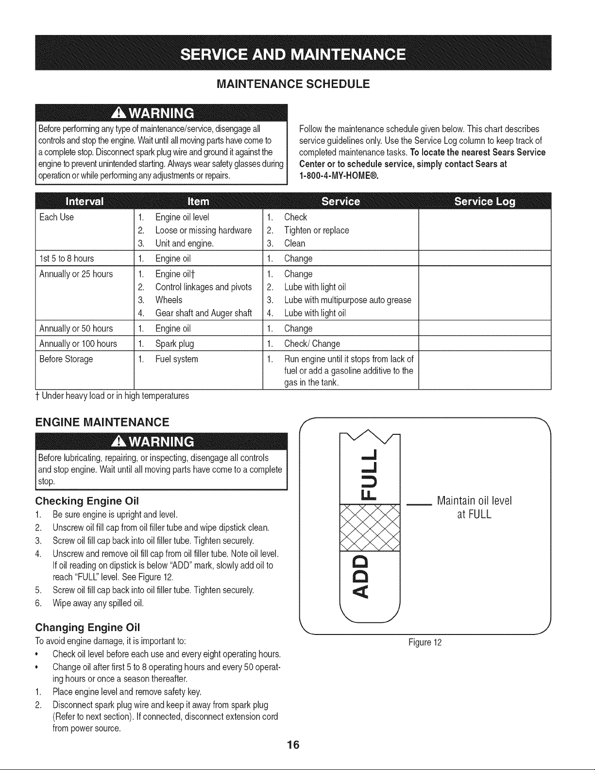
Checking Engine Oil
1. Be sureengine is uprightand level.
2. Unscrewoil fill capfromoil fillertubeand wipe dipstickclean.
3. Screwoil fill capbackintooil fillertube.Tightensecurely.
4. Unscrewand removeoilfill cap fromoilfiller tube.Noteoil level.
Ifoil readingon dipstick isbelow"ADD"mark,slowlyadd oil to
reach"FULL"level.See Figure12.
5. Screwoil fill capbackintooil fillertube.Tightensecurely.
6. Wipeawayany spilledoil.
Changing Engine Oil
Toavoidenginedamage,it is importantto:
• Checkoil levelbeforeeachuseandeveryeightoperatinghours.
• Changeoil afterfirst 5 to 8 operatinghoursand every 50 operat-
inghoursor oncea seasonthereafter.
1. Placeengineleveland removesafetykey.
2. Disconnectsparkplugwireand keepit awayfrom sparkplug
(Referto nextsection).Ifconnected,disconnectextensioncord
frompowersource.
f
16
..J
,,.J
U.,
a
a
Maintain oil level
at FULL
Figure12
J
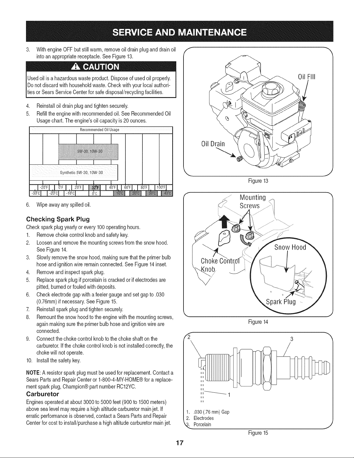
3. WithengineOFFbutstillwarm,removeoildrainpluganddrainoil
intoanappropriatereceptacle.SeeFigure13.
Usedoilisahazardouswasteproduct.Disposeofusedoilproperly.
IDonotdiscardwithhouseholdwaste.Checkwithyourlocalauthori-
Ities or SearsServiceCenterfor safedisposal/recyclingfacilities.
4. Reinstalloildrainplugandtightensecurely.
5. Refillthe enginewith recommendedoil. SeeRecommendedOil
Usagechart.The engine'soil capacityis 20 ounces.
Recommended Oil Usage
0il FIll
Oil Drain
Figure13
6. Wipeawayany spilledoil.
Checking Spark Plug
Checksparkplug yearlyor every100operatinghours.
1. Removechokecontrolknobandsafetykey.
2. Loosenand removethe mountingscrewsfromthe snow hood.
SeeFigure14.
3. Slowlyremovethe snow hood,makingsurethatthe primerbulb
hoseand ignitionwireremainconnected.See Figure14inset.
4. Removeandinspectspark plug.
5. Replacesparkplug if porcelainiscrackedor if electrodesare
pitted,burnedor fouledwith deposits.
6. Checkelectrodegap with a feelergaugeand set gap to .030
(0.76ram)if necessary.See Figure15.
7. Reinstallsparkplugandtightensecurely.
8. Remountthe snowhoodto the enginewith themountingscrews,
againmakingsurethe primerbulb hoseand ignitionwireare
connected.
9. Connectthe chokecontrolknobto thechoke shafton the
carburetor.If the chokecontrol knobisnot installedcorrectly,the
chokewill notoperate.
10. Installthe safetykey.
NOTE:A resistorsparkplugmustbe usedfor replacement.Contacta
SearsPartsand RepairCenteror 1-800-4-MY-HOME®for a replace-
mentsparkplug,Champion®partnumberRC12YC.
Carburetor
Enginesoperatedat about3000 to 5000 feet (900 to 1500meters)
abovesealevelmay requirea high altitudecarburetormainjet. If
erraticperformanceis observed,contacta SearsPartsand Repair
Centerfor costto install/purchasea high altitudecarburetormainjet.
,,!
17
g
Screws
Figure14
1..030 (.76 mm)Gap
2. Electrodes
_. Porcelain
Figure15
Engine Speed
Toavoidserious injuryor death, DONOTmodifyenginein any
way.Tamperingwiththe governorsettingcan causethe engineand
equipmentto operateat unsafespeeds.NEVERtamperwithfactory
settingof enginegovernor.Runningthe enginefasterthan the speed
setat thefactory is dangerous.
LUBRICATION
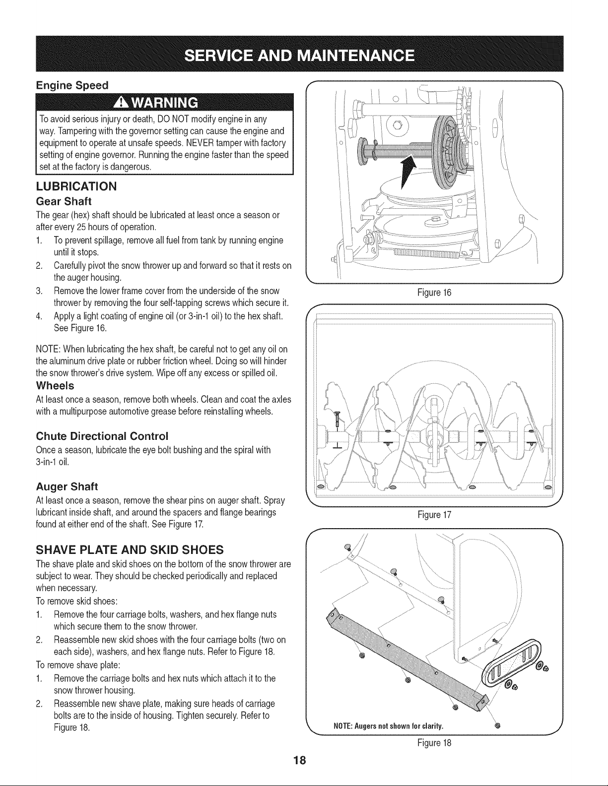
Gear Shaft
Thegear (hex)shaft shouldbe lubricatedat least oncea seasonor
afterevery25 hoursof operation.
1. Topreventspillage,removeall fuel fromtank by runningengine
until it stops.
2. Carefullypivotthe snowthrowerupandforwardso that itrestson
theauger housing.
3. Removethe lowerframecover fromthe undersideof the snow
throwerby removingthe four self-tappingscrewswhichsecureit.
4. Applya lightcoatingof engineoil (or 3-in-1oil) to the hexshaft.
SeeFigure16.
NOTE:Whenlubricatingthe hexshaft, be carefulnotto get any oil on
thealuminumdriveplateor rubberfrictionwheel. Doingsowill hinder
the snowthrower'sdrive system.Wipeoff anyexcessor spilledoil.
Wheels
At leastoncea season,removebothwheels.Cleanandcoattheaxles
witha multipurposeautomotivegreasebeforereinstallingwheels.
Chute Directional Control
Oncea season,lubricatethe eye boltbushingand thespiralwith
3-in-1oil.
Auger Shaft
At leastoncea season,removethe shearpinson augershaft.Spray
lubricantinsideshaft,and aroundthe spacersandflangebearings
foundat eitherend of the shaft. See Figure17.
SHAVE PLATE AND SKID SHOES
The shaveplateand skidshoesonthe bottomof the snowthrowerare
subjectto wear.They shouldbe checkedperiodicallyandreplaced
whennecessary.
To removeskidshoes:
1. Removethe four carriagebolts,washers,and hex flangenuts
whichsecurethemto the snowthrower.
2. Reassemblenew skid shoeswith the fourcarriagebolts(twoon
eachside), washers,and hex flangenuts.Referto Figure18.
To removeshaveplate:
1. Removethe carriageboltsand hexnuts whichattachit to the
snowthrowerhousing.
2. Reassemblenew shaveplate,makingsureheadsof carriage
boltsareto the insideof housing.Tightensecurely.Referto
Figure18.
J
Figure16
,,.
Figure17
\
x X \
\
\\
NOTE:Angers notshownfor clarity.
Figure18
18
ADJUSTMENTS
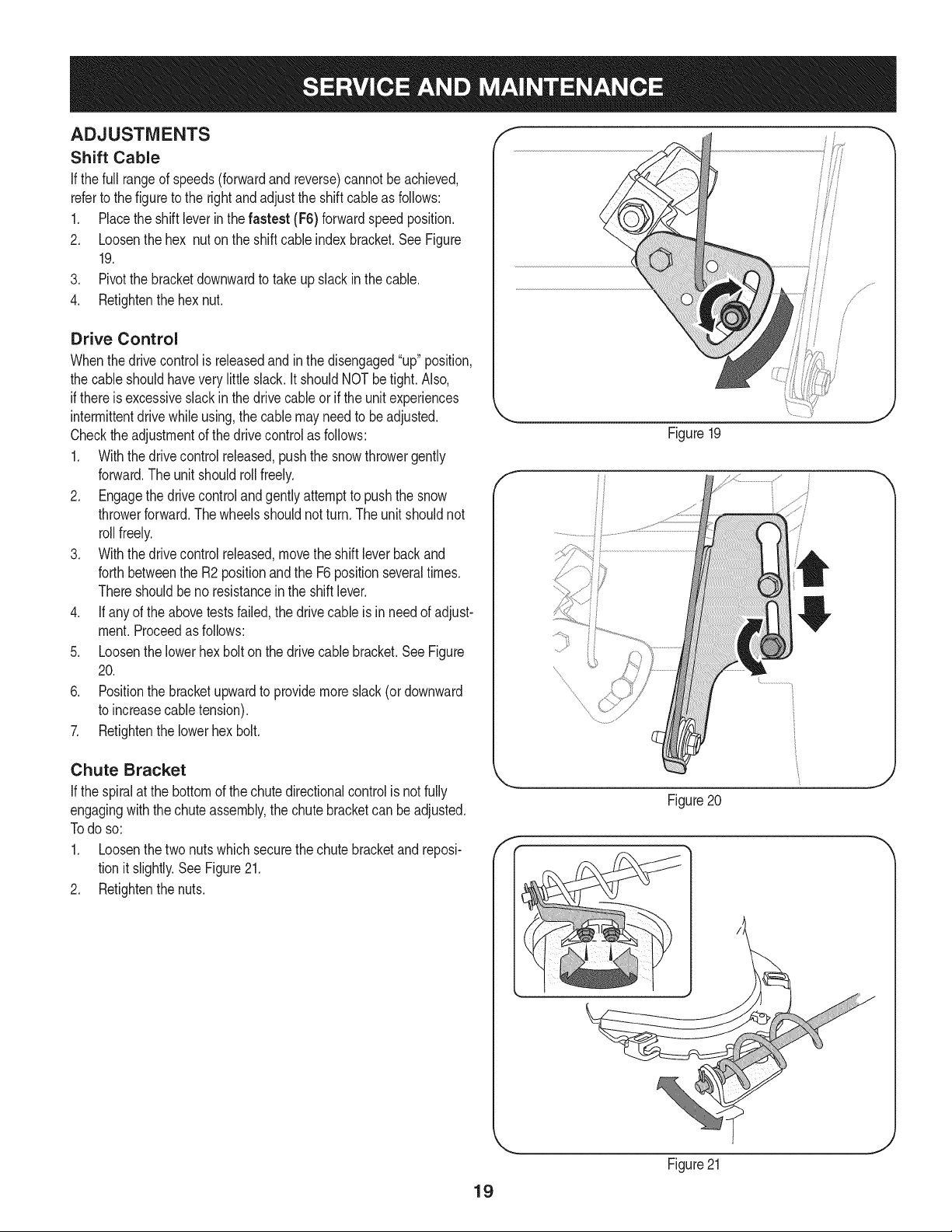
Shift Cable
If thefull rangeof speeds(forwardand reverse)cannotbe achieved,
referto the figureto the rightand adjustthe shift cableas follows:
1. Placethe shiftleverin thefastest (F6) forwardspeedposition.
2. Loosenthe hex nuton the shiftcable indexbracket.SeeFigure
19.
3. Pivotthe bracketdownwardto takeupslack inthe cable.
4. Retightenthehex nut.
Drive Control
Whenthedrivecontrol is releasedandin thedisengaged"up"position,
the cableshouldhaveverylittle slack.It shouldNOTbetight. Also,
if thereis excessiveslackin thedrive cableor if the unitexperiences
intermittentdrivewhileusing,the cable mayneed to be adjusted.
Checktheadjustmentof the drivecontrolas follows:
1. Withthedrivecontrol released,pushthe snowthrowergently
forward.The unitshouldroll freely.
2. Engagethe drivecontroland gentlyattemptto pushthe snow
throwerforward.Thewheelsshouldnotturn. The unitshouldnot
rollfreely.
3. With thedrivecontrol released,movethe shift leverbackand
forthbetweenthe R2positionand the F6 positionseveraltimes.
Thereshouldbe no resistancein the shiftlever.
4. If anyof the abovetests failed,the drivecable is in needof adjust-
ment.Proceedas follows:
5. Loosenthe lowerhexbolt onthe drivecable bracket.See Figure
20.
6. Positionthe bracketupwardto providemoreslack(or downward
to increasecabletension).
7. Retightenthe lowerhex bolt.
Chute Bracket
If the spiralat the bottomof the chutedirectionalcontrol is notfully
engagingwiththe chuteassembly,the chute bracketcan beadjusted.
Todo so:
1. Loosenthe two nutswhichsecurethechutebracketand reposi-
tion it slightly.See Figure21.
2. Retightenthe nuts.
Figure19
f
Figure20
f
19
Figure21
Auger Control f "_
Referto the Assemblysectionfor instructionsonadjustingtheauger
controlcable.
Skid Shoes
Referto the Assemblysectionfor instructionsonadjustingthe skid
shoes.
BELT REPLACEMENT
Auger Belt
To removeandreplaceyoursnow thrower'saugerbelt,proceedas
follows:
1. Topreventspillage,removeall fuel fromtank by runningengine
until itstops.
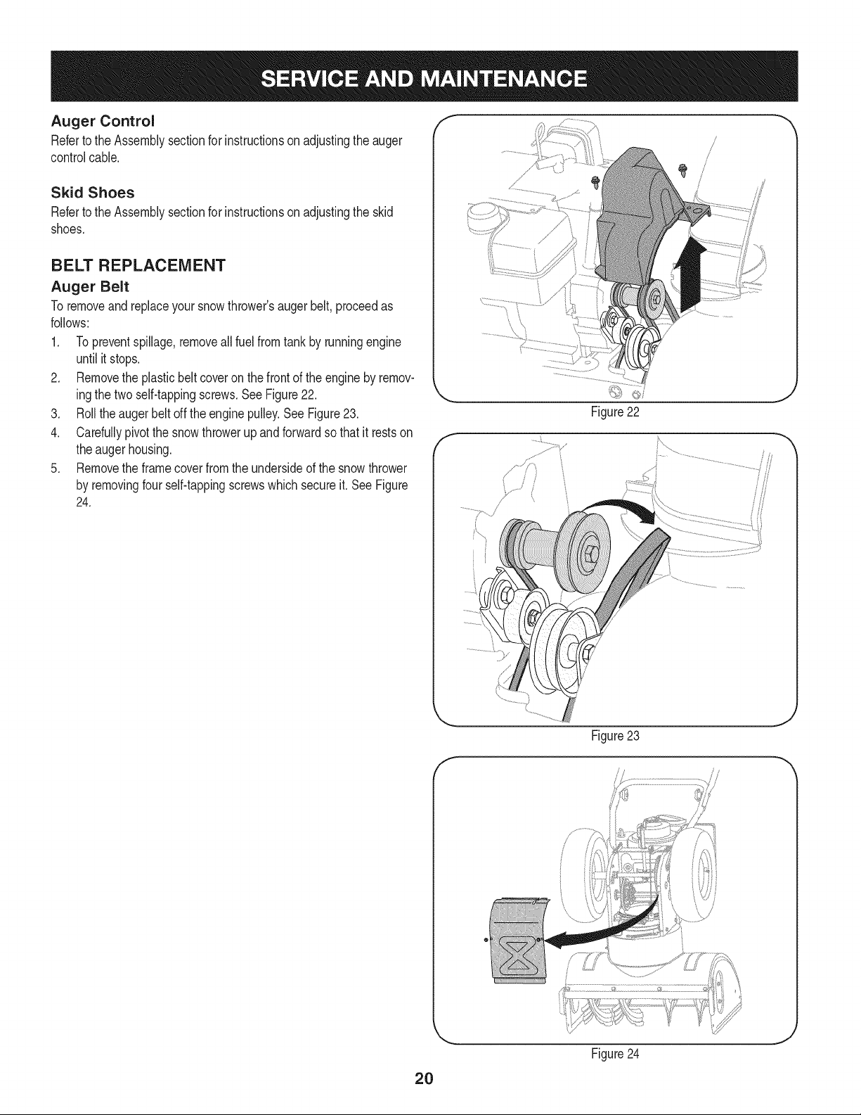
2. Removethe plasticbelt coveron the front of the engineby remov-
ingthe twoself-tappingscrews.See Figure22.
3. Rollthe auger beltoff theengine pulley.See Figure23.
4. Carefullypivotthe snowthrowerupandforwardso that itrestson
theauger housing.
5. Removethe framecoverfromthe undersideof the snow thrower
by removingfourself-tappingscrewswhichsecureit.SeeFigure
24.
f
Figure22
J
f
Figure 23
//
2O
Figure24
J
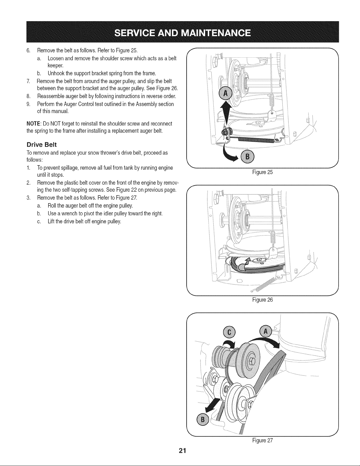
6. Removethebeltasfollows.RefertoFigure25.
a. Loosenandremovetheshoulderscrewwhichactsasabelt
keeper.
b. Unhookthesupportbracketspringfromtheframe.
7. Removethebeltfromaroundtheaugerpulley,andslipthebelt
betweenthesupportbracketandtheaugerpulley.SeeFigure26.
8. Reassembleaugerbeltbyfollowinginstructionsinreverseorder.
9. PerformtheAugerControltestoutlinedintheAssemblysection
ofthismanual.
NOTE:DoNOTforgettoreinstalltheshoulderscrewandreconnect
thespringtotheframeafterinstallingareplacementaugerbelt.
Drive Belt
Toremoveand replaceyoursnow thrower'sdrivebelt, proceedas
follows:
1. Topreventspillage,removeall fuel fromtank by runningengine
untilit stops.
2. Removetheplasticbelt coveronthe frontof the engineby remov-
ingthe twoself-tappingscrews.See Figure22on previouspage.
3. Removethebelt as follows.Referto Figure27.
a. Rollthe auger beltoff theengine pulley.
b. Use a wrenchto pivotthe idlerpulleytowardthe right.
c. Liftthe drivebelt off enginepulley.
/" }
Figure25
Figure26
21
Figure27
4, Carefullypivotthesnowthrowerupandforwardsothatitrestson
theaugerhousing.
5. Removetheframecoverfromtheundersideofthesnowthrower
byremovingfourself-tappingscrewswhichsecureit.Referto
Figure24,
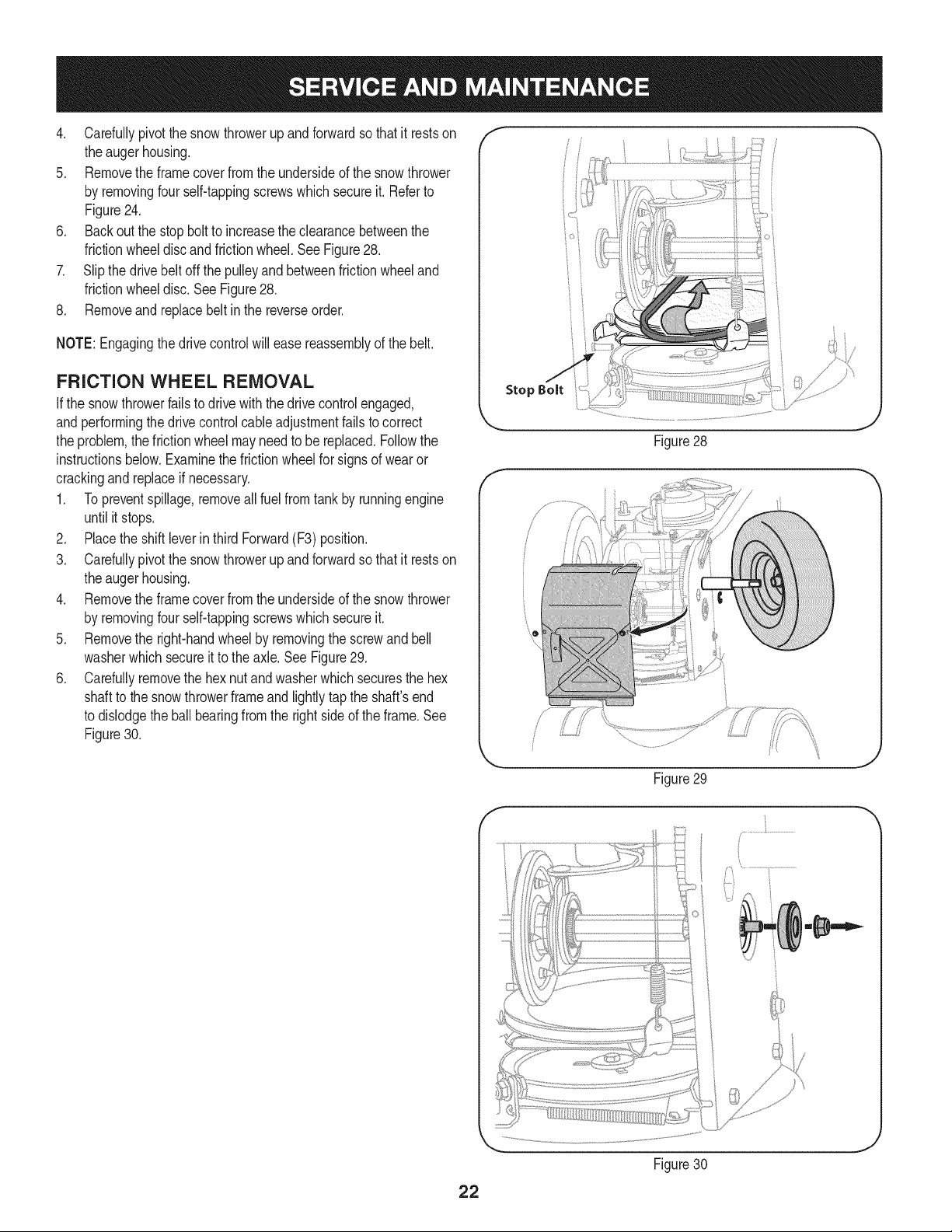
6. Backoutthestopbolttoincreasetheclearancebetweenthe
frictionwheeldiscandfrictionwheel,SeeFigure28,
7. Slipthedrivebeltoffthepulleyandbetweenfrictionwheeland
frictionwheeldisc,SeeFigure28,
8, Removeandreplacebeltinthereverseorder,
NOTE:Engagingthedrivecontrolwilleasereassemblyofthebelt.
FRICTION WHEEL REMOVAL
Ifthe snowthrowerfailsto drive withthedrivecontrol engaged,
andperformingthe drivecontrolcableadjustmentfails to correct
the problem,the frictionwheelmayneed to be replaced.Followthe
instructionsbelow.Examinethe frictionwheelfor signsof wearor
crackingand replaceif necessary.
1. Topreventspillage,removeall fuel fromtank by runningengine
until it stops.
2. Placethe shiftleverin third Forward(F3) position.
3. Carefullypivotthe snowthrowerupandforwardso that it restson
theauger housing.
4. Removethe framecoverfromthe undersideof the snow thrower
by removingfourself-tappingscrewswhichsecureit.
5. Removethe right-handwheelby removingthe screwandbell
washerwhichsecureit to theaxle. See Figure29.
6. Carefullyremovethe hexnut andwasherwhichsecuresthe hex
shaftto the snowthrowerframeand lightlytap the shaft'send
to dislodgethe ball bearingfrom the rightsideof theframe.See
Figure30.
Stop Bolt
Figure28
/ ii
Figure29
J
/
22
Figure30
NOTE:Becarefulnottodamagethethreadsontheshaft,
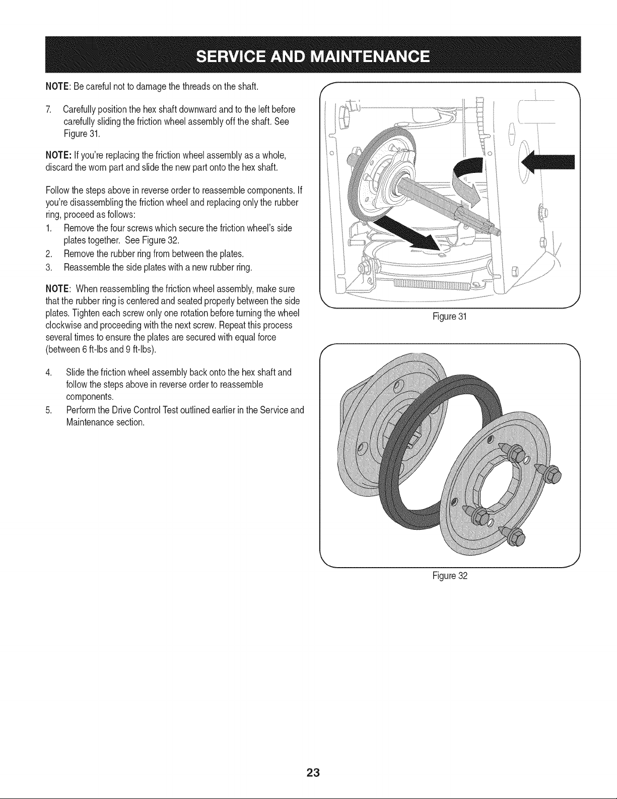
7. Carefullypositionthehexshaftdownwardandtotheleftbefore
carefullyslidingthefrictionwheelassemblyofftheshaft.See
Figure31.
NOTE:Ifyou'rereplacingthefrictionwheelassemblyasawhole,
discardthewornpartandslidethenewpartontothehexshaft.
Followthestepsaboveinreverseordertoreassemblecomponents.If
you'redisassemblingthefrictionwheelandreplacingonlytherubber
ring,proceedasfollows:
1. Removethefourscrewswhichsecurethefrictionwheel'sside
platestogether.SeeFigure32.
2. Removetherubberringfrombetweentheplates.
3. Reassemblethesideplateswithanewrubberring.
NOTE:Whenreassemblingthefrictionwheelassembly,makesure
thattherubberringiscenteredandseatedproperlybetweentheside
plates.Tighteneachscrewonlyonerotationbeforeturningthewheel
clockwiseandproceedingwiththenextscrew.Repeatthisprocess
severaltimestoensuretheplatesaresecuredwithequalforce
(between6ft-lbsand9ft-lbs).
4. Slidethefrictionwheelassemblybackontothehexshaftand
followthestepsaboveinreverseordertoreassemble
components.
5. PerformtheDriveControlTestoutlinedearlierintheServiceand
Maintenancesection.
Figure31
... j
Figure32
23
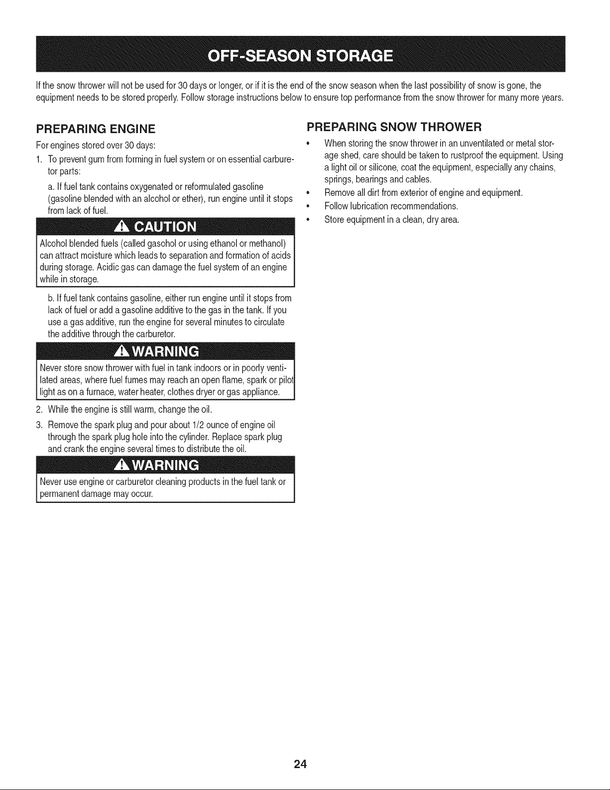
Ifthe snowthrowerwillnot be usedfor30 daysor longer,or if it is the end of the snowseasonwhenthe last possibilityof snowis gone,the
equipmentneedsto be storedproperly.Followstorageinstructionsbelowto ensuretop performancefromthe snowthrowerfor manymoreyears.
PREPARING ENGINE
Forenginesstoredover30 days:
1. Topreventgum from formingin fuel systemoron essentialcarbure-
tor parts:
a. If fueltank containsoxygenatedor rdormulatedgasoline
(gasolineblendedwithan alcoholor ether), run engineuntilit stops
fromlackof fuel.
Alcoholblendedfuels (calledgasoholor usingethanolor methanol)
canattract moisturewhichleadsto separationandformationof acids
duringstorage.Acidicgas can damagethefuel systemof an engine
_wh e n storage.
b. If fueltank containsgasoline,eitherrun engineuntilit stopsfrom
lackof fuel oradda gasolineadditiveto the gas inthe tank. Ifyou
usea gas additive,runthe enginefor severalminutesto circulate
theadditivethroughthecarburetor.
Neverstoresnowthrowerwithfuel intank indoorsor in poorlyventi-
latedareas,wherefuel fumesmayreachan openflame,sparkor pilol
lightas ona furnace,waterheater,clothesdryer orgas appliance.
.
3.
Whiletheengine is still warm,changethe oil.
Removethe sparkplug and pourabout 1/2 ounceof engineoil
throughthe sparkplug hole into the cylinder.Replacesparkplug
andcrankthe engineseveraltimesto distributethe oil.
PREPARING SNOW THROWER
• Whenstoringthe snowthrowerin anunventilatedor metal stor-
age shed,careshouldbe takento rustprooftheequipment.Using
a light oil or silicone,coat theequipment,especiallyanychains,
springs,bearingsandcables.
• Removealldirt fromexteriorof engineandequipment.
• Followlubricationrecommendations.
• Storeequipmentin a clean,dry area.
Neveruseengineor carburetorcleaningproductsin the fueltank or
permanentdamagemayoccur.
24
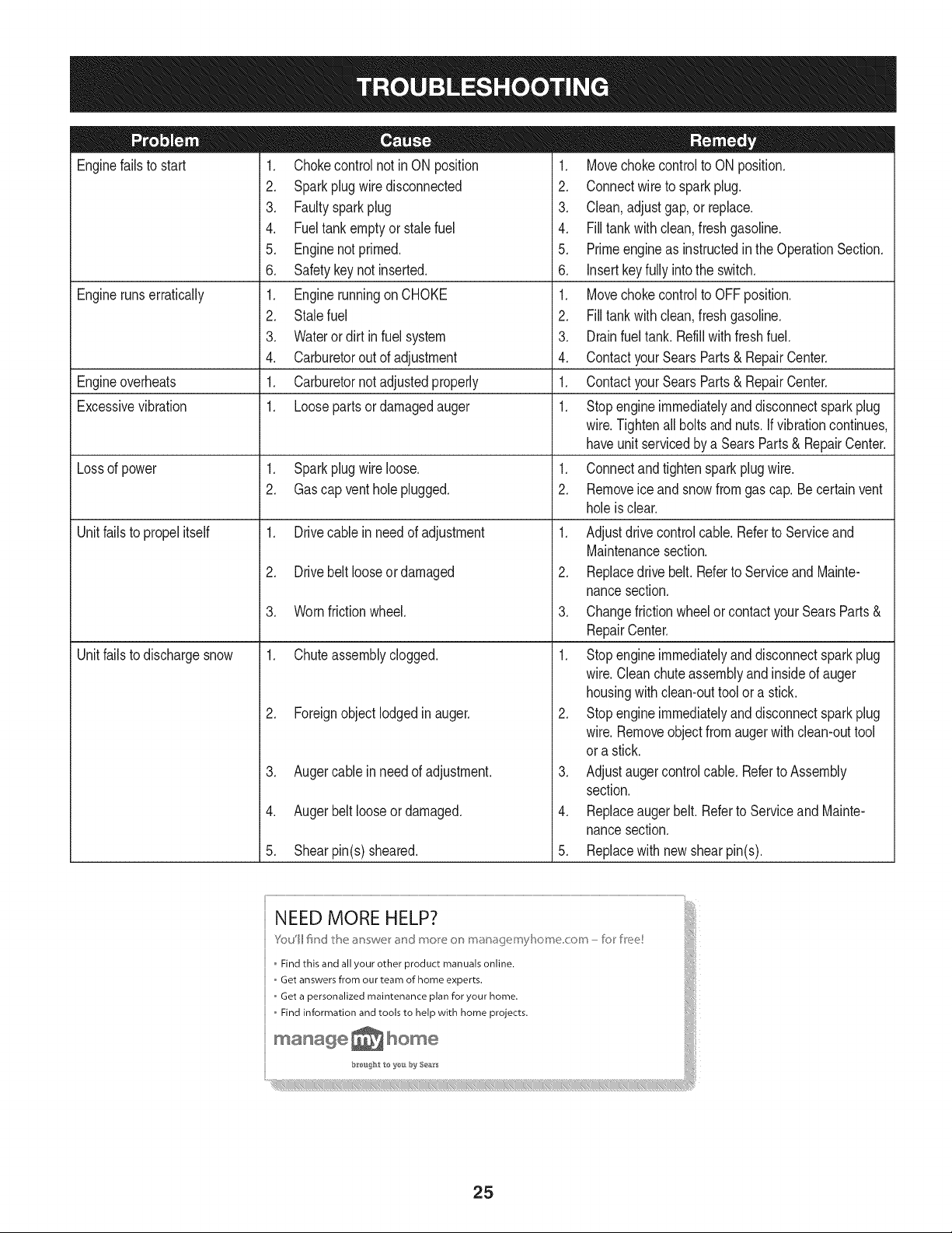
Enginefailsto start
Enginerunserratically
Engineoverheats
Excessivevibration
Lossof power
Unitfailsto propelitself
Unitfailsto dischargesnow
1. Chokecontrolnot in ON position
2. Sparkplugwire disconnected
3. Faultysparkplug
4. Fueltank emptyor stale fuel
5. Enginenotprimed.
6. Safetykeynot inserted.
1. Enginerunningon CHOKE
2. Stalefuel
3. Wateror dirt in fuel system
4. Carburetorout of adjustment
1. Carburetornot adjustedproperly
1. Loosepartsor damagedauger
1. Sparkplugwire loose.
2. Gascap vent hole plugged.
1. Drivecable in need of adjustment
2. Drivebelt looseor damaged
3. Wornfrictionwheel.
1. Chuteassemblyclogged.
2. Foreignobjectlodgedinauger.
3. Augercablein needof adjustment.
4. Augerbelt looseor damaged.
5. Shearpin(s) sheared.
1. Movechokecontrolto ONposition.
2. Connectwireto sparkplug.
3. Clean,adjustgap,or replace.
4. Filltank with clean, freshgasoline.
5. Primeengineas instructedinthe OperationSection.
6. Insertkeyfully intothe switch.
1. Movechokecontrolto OFFposition.
2. Filltank with clean, freshgasoline.
3. Drainfueltank. Refillwith freshfuel.
4. ContactyourSearsParts& RepairCenter.
1. ContactyourSearsParts& RepairCenter.
1. Stopengineimmediatelyand disconnectsparkplug
wire.Tightenall boltsand nuts.Ifvibrationcontinues,
haveunitservicedbya SearsParts& RepairCenter.
1. Connectandtightensparkplugwire.
2. Removeice andsnowfromgascap. Be certain vent
holeis clear.
1. Adjustdrivecontrolcable. Referto Serviceand
Maintenancesection.
2. Replacedrive belt. Referto Serviceand Mainte-
nancesection.
3. Changefrictionwheelor contactyour SearsParts&
RepairCenter.
1. Stopengineimmediatelyand disconnectsparkplug
wire.Cleanchuteassemblyand insideof auger
housingwith clean-outtool or a stick.
2. Stopengineimmediatelyand disconnectsparkplug
wire.Removeobjectfrom augerwith clean-outtool
ora stick.
3. Adjustaugercontrolcable. Referto Assembly
section.
4. Replaceauger belt. Referto ServiceandMainte-
nancesection.
5. Replacewith new shearpin(s).
25
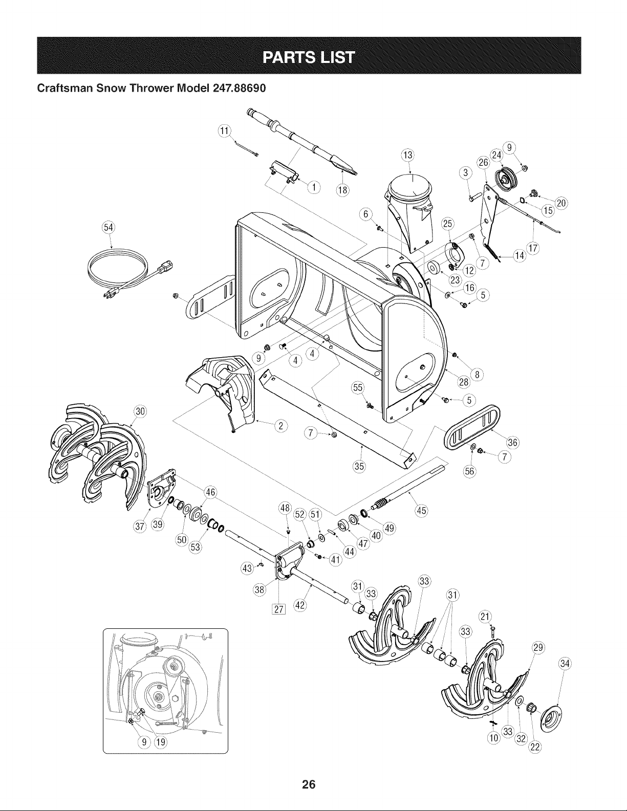
Craftsman Snow Thrower Model 247.88690
Y
I
L.
--.
i i\:/,
i
!
_k
t\ 7_
26
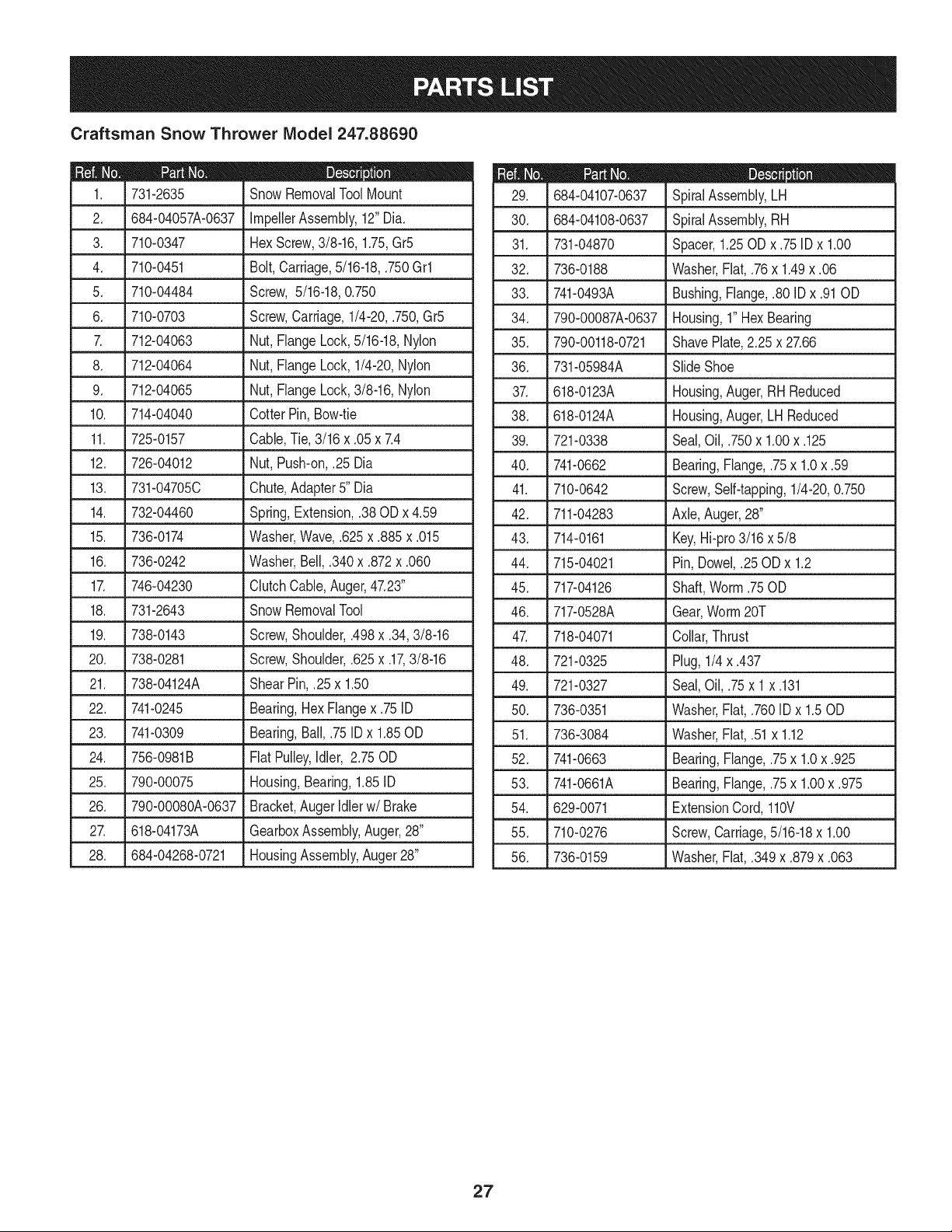
Craftsman Snow Thrower IViodel 247.88690
D = 0
731-2635 Snow RemovalToolMount
2. 684-04057A-0637 ImpellerAssembly,12"Dia.
3. 710-0347 HexScrew,3/8-16, 1.75,Gr5
4. 710-0451 Bolt,Carriage,5/16-18,.750Grl
5. 710-04484 Screw, 5/16-18,0.750
6. 710-0703 Screw,Carriage,1/4-20,.750,Gr5
7. 712-04063 Nut,FlangeLock,5/16-18,Nylon
8. 712-04064 Nut,FlangeLock,1/4-20,Nylon
9. 712-04065 Nut,FlangeLock,3/8-16, Nylon
10. 714-04040 Cotter Pin,Bow-tie
11. 725-0157 Cable,Tie, 3/16 x .05x 7.4
12. 726-04012 Nut,Push-on,.25 Dia
13. 731-04705C Chute,Adapter5" Dia
14. 732-04460 Spring,Extension,.38 ODx 4.59
15. J 736-0174 1Washer,Wave,.625x .885 x .015
16. 736-0242 Washer,Bell,.340x .872x .060
17. 746-04230 ClutchCable,Auger,47.23"
18. 731-2643 SnowRemovalTool
19. 738-0143 Screw,Shoulder,.498x .34,3/8-16
20. 738-0281 Screw,Shoulder,.625x .17,3/8-16
21. 738-04124A ShearPin,.25 x 1.50
22. 741-0245 Bearing,HexFlangex .75ID
23. 741-0309 Bearing,Ball,.75ID x 1.85OD
24. 756-0981B FiatPulley,Idler, 2.75OD
25. 790-00075 Housing,Bearing,1.85ID
26. 790-00080A-0637 Bracket,Auger Idlerw/Brake
27. 618-04173A GearboxAssembly,Auger,28"
28. 684-04268-0721 HousingAssembly,Auger28"
684-04107-0637
30. 684-04108-0637
31. 731-04870
32. 736-0188
33. 741-0493A
34. 790-00087A-0637
35. 790-00118-0721
36. 731-05984A
37. 618-0123A
38. 618-0124A
39. 721-0338
40. 741-0662
41. 710-0642
42. 711-04283
43. 714-0161
44. 715-04021
45. 717-04126
46. 717-0528A
D = B 0
SpiralAssembly,LH
SpiralAssembly,RH
Spacer,1.25OD x .75 ID x 1.00
Washer,Flat, .76x 1.49x .06
Bushing,Flange,.80 IDx .91OD
Housing,1"HexBearing
ShavePlate,2.25x 27.66
SlideShoe
Housing,Auger,RHReduced
Housing,Auger,LH Reduced
Seal,Oil, .750x 1.00x .125
Bearing,Flange,.75x 1.0x .59
Screw,Self-tapping,1/4-20,0.750
Axle,Auger,28"
Key,Hi-pro3/16 x 5/8
Pin, Dowel,.25OD x 1.2
Shaft,Worm.75OD
Gear,Worm20T
47. 718-04071 Collar,Thrust
48. 721-0325 Plug,1/4 x .437
49. 721-0327 Seal,Oil, .75x 1 x .131
50. 736-0351 Washer,Flat, .760ID x 1.50D
51. 736-3084 Washer,Flat, .51x 1.12
52. 741-0663 Bearing,Flange,.75x 1.0x .925
53. 741-0661A Bearing,Flange,.75x 1.00x .975
54. 629-0071 ExtensionCord,110V
55. 710-0276 Screw,Carriage,5/16-18x 1.00
56. 736-0159 Washer,Flat, .349x .879x .063
27
Craftsman Snow Thrower Model 247.88690
28
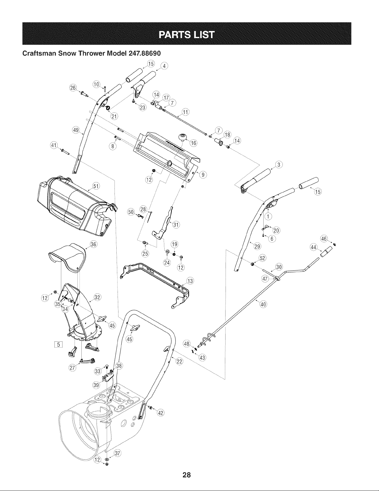
Craftsman Snow Thrower IViodel 247.88690
m = 0
631-04133A HandleAssembly,ClutchLock, LH
2. 631-04134B HandleAssembly,ClutchLock, RH
3. 684-04111B HandleAss'y, Engage,LH
4. 684-04112B HandleAss'y, Engage,RH
5. J 631-04131B _ ChuteAssembly(IncludesRef.# 27)
6. 710-04326 Screw,#8-16x .50
7. 710-3069 Screw,1/4-20,.50
8. 710-04586 Screw,1/4-20,1.625,Gr5
9. 790-00219-0721 Panel,Handle,(no cutout)
10. 710-1233 Screw,Machine,#10-24,1.375
11. 684-04250 PivotRod
12. 712-04063 Nut, FlangeLock,5/16-18,Nylon
13. .790-00248B-0637 _Bracket,Panel
14. 712-04081A Nut, Hex,1/4-20,Shoulder
15. 720-0274 Grip, 1.0IDx 5.0
16. 720-04039 Knob,Shift,Black
17. 731-04894D LockPlate
18. 731-04896B Cam,ClutchLock
19. 732-0193 Spring,.39x .60x .88
20. 732-04219C Spring,ClutchLock
21. 732-04238 Spring,Torsion,0.8156IDx .3038
22. 749-04138A-0637 Handle,Lower
23. 735-0199A Bumper,Rubber,.62ODx .22
24. 736-0262 Washer,Fiat,.385x .870x .092
25. 738-04118 Bolt,Shoulder,5/16-18x 0.905
26. 738-04348 Screw,Shoulder,.43x 1.3,1/4-20
D = W O
731-04869 Chute,FlangeKeeper
28. 746-04397 Cable,SpeedSelector
29. 749-04191A-0637 Handle,Upper,LH
30. 747-0697 Eye Bolt,ChuteCrank
31. 790-00313-0637 ShiftLever
32. 731-04912B Chute,Lower,5.0 Dia.
33. 710-0276 Bolt,Carriage,5/16-18,1.0
34. 710-04071 Bolt,Carriage,5/16-18,1.0
35. 710-0451 Bolt,Carriage,5/16-18,.750
36. 731-04426A Chute,Upper,w/Label
37. 736-0159 Washer,.349x .879x .063
38. 741-0475 Bushing,Plastic,.380
39. 784-5647-0637 Bracket,ChuteCrank
40. 684-04104-0637 CrankAssembly,Chute
41. 710-0449 Screw,Carriage,5/16-18,2.25
42. 710-04484 Screw,5/16-18,2.25,Gr5
43. 714-0104 Pin, Cotter,.072x 1.13
44. 720-0201A CrankKnob,1.0Dia.x 3.2, Black
45. 720-0284 Knob,5/16-18,Black
46. 726-0100 Cap,Push,3/8 Rod
47. 735-0234 Grommet,.44 ID x .94OD x .50
48. 736-0185 Washer,Fiat,.375x .738x .063
49. 749-04190A-0637 Handle,Upper,RH
50. 714-0145 Click Pin
51. 731-06471 HandlePanelCover
52. 712-3010 Nut, Hex,5/16-18
29
Craftsman Snow Thrower Model 247.88690
S //
/
/
/
//
/
3O
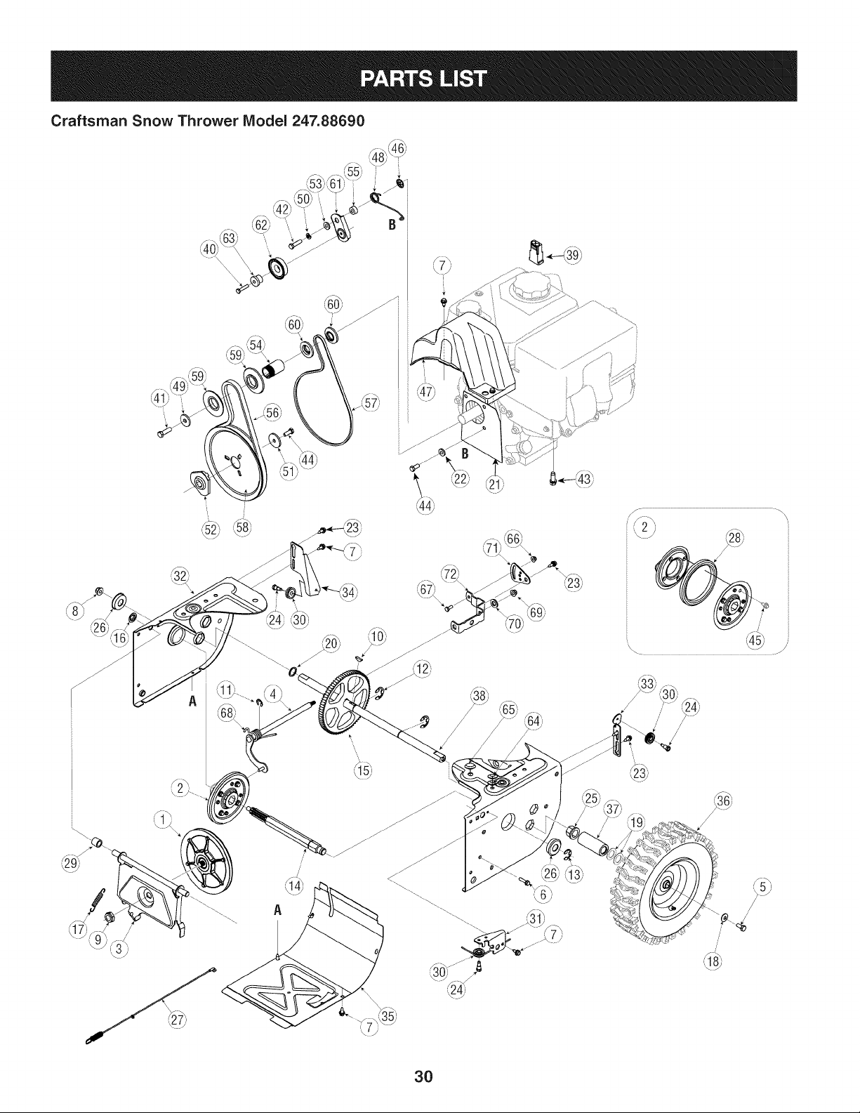
Craftsman Snow Thrower IViodel 247.88690
D = 0 0
656-04025A DiscAssembly,FrictionWheel
2. 684-04153 FrictionWheelAssembly,5.50D
3. 684-04154-0637 SupportBracket,FrictionWheel
4. 684-04156A ShiftAssembly,Rod
5. J 710-0627 Hex Screw,5/16-24,.750,Gr5
6. 710-0788 Screw,1/4-20,1.000
7. 710-1652 Screw,1/4-20x .625
8. 712-04065 Nut,FlangeLock,3/8-16,Nylon
9. 712-0417A Nut,Flange,5/8-18
10. 714-0126 Key,Hi Pro,3/16 x 3/4 Dia.
11. 716-0104 E-ring,.500 Dia.
12. 716-0136 E-ring,Retaining, .875Dia.
13. 716-0231 E-ring,.750Dia.
14. 717-04209A HexShaft, .8125,7-Tooth
15. 717-04230 Gear,80-Tooth
16. _726-0221 LSpeedNut,.500
1_ 732-0264
18. 736-0242
19. 736-0287
20. 736-04161
21. 790-00289A-0637
22. 748-0234
23. 738-04184A
24. 738-0924A
ExtensionSpring
Washer,Bell,.340x .872x .060
Washer,Flat,.793x 1.24x .060
Washer,Flat,.75x 1.00x .060
Pit.,Cvr.
ShoulderSpacer
Screw,Shoulder,.37x .105,1/4-20
Screw,1/4-28,.375
25. 741-0245
26. 741-0563
2_ 746-04229
28. 735-04054
29. 748-0190
30. 756-0625
31. 790-00096-0637
32. 790-00180A-0721
Bearing,HexFlangex .75ID
Bearing,Ball,17x 40 x 12
ClutchCable,Wheel,44.95"
Rubber,FrictionWheel,5.50D
Spacer,.508ID x .75OD x .68
Roller,Cable
FrontGuideBracket,AugerCable
Frame
33. 790-00206A-0637 Guide Bracket,AugerCable
34. 790-00207B GuideBracket,DriveCable
35. 790-00316-0637 Cover,Frame
36. 634-04147A-0911 LHWheelAssembly,15x 5 x 6
D = O O
634-04148A-0911 RHWheelAssembly,15x 5 x 6
37. 731-04873 Spacer,1.25x .75x 3.0
38. 738-04168 Axle,.75x 22"
39. 790-00218A-0637 Shift Bracket,Speed Selector
40. 710-0809 HexScrew,1/4-20,1.25,Gr5
41. 710-0191 HexScrew,3/8-24,1.25,Gr8
42. 710-0672 HexScrew,5/16-24,1.25,Gr5
43. 710-0654A Screw,Seres,3/8-16,1.00
44. 710-1245B HexScrew,5/16-24,.875,Gr8
45. 710-0896 Screw,1/4-20x .625
46. 726-04012 Nut,Push-on,.25 Dia.
47. 731-04792A Cover,Belt
48. 732-04308A Spring,Torsion,.850 ID x .354
49. 736-0247 Washer,Flat, .406x 1.25x .157
50. 736-0119 Washer,Lock .3125
51. 736-0505 Washer,Flat, .34x 1.50x .150
52. 748-04053A Pulley,Adapter,.75 Dia.
53. 748-04112B Spacer,Shoulder,.317x .50x .102
54. 750-04303 Spacer,.875ID x 1.185OD
55. 750-04477 Spacer,.340x .750x .360
56. 754-04050 Belt,AugerDrive
57. 754-0367 Belt,Wheel Drive
58. 756-04109 Pulley,Auger Drive,8.1x .5
59. 756-04113 Pulley,Half,V x 2.600 OD
60. 756-04252 Pulley,Half,3/8-V x 1.7160OD
61. 790-00208C IdlerBracket,Wheel Drive
62. 684-04169 IdlerPulleyAssembly
63. 750-04571 Spacer,Shoulder,.26x .79x .538
64. 735-04099 Plug,3/8 ID
65. 735-04100 Plug,1/2 ID
66. 712-04064 Nut,FlangeLock,1/4-20,Nylon
67. 710-0751 HexScrew,1/4-20,.620,Gr5
68. 732-04311 Spring,Torsion,.750ID x .968
69. 712-04063 Nut,FlangeLock,5/16-18,Nylon
70. 736-3015 Wash.,Flat,.469x .875x .105
71. 790-00217A-0637 PivotBracket,SpeedSelector
31
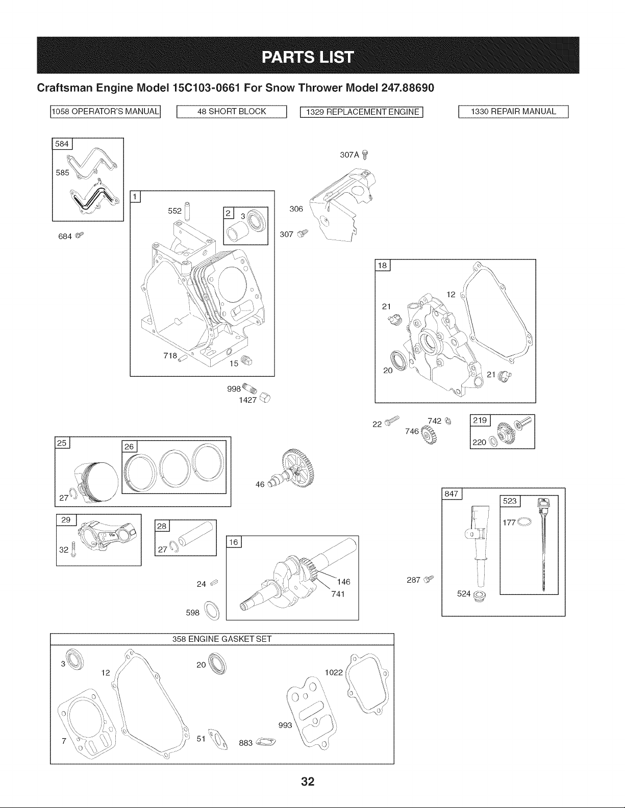
Craftsman Engine Model 15C103-0661 For Snow Thrower Model 247.88690
110580PERATOR'sMANUAL] I 48 SHORT BLOCK I I 1329 REPLACEMENT ENGINE I 1 1330 REPAIR MANUAL I
307A _
684 t)_'
718
21
22U
742 %
24 0
598
46
741
287 G_
177 ,:.C,_
' i
f
524 __?)
358 ENGINE GASKET SET
12
2O
1022
993
51
883 _3
32
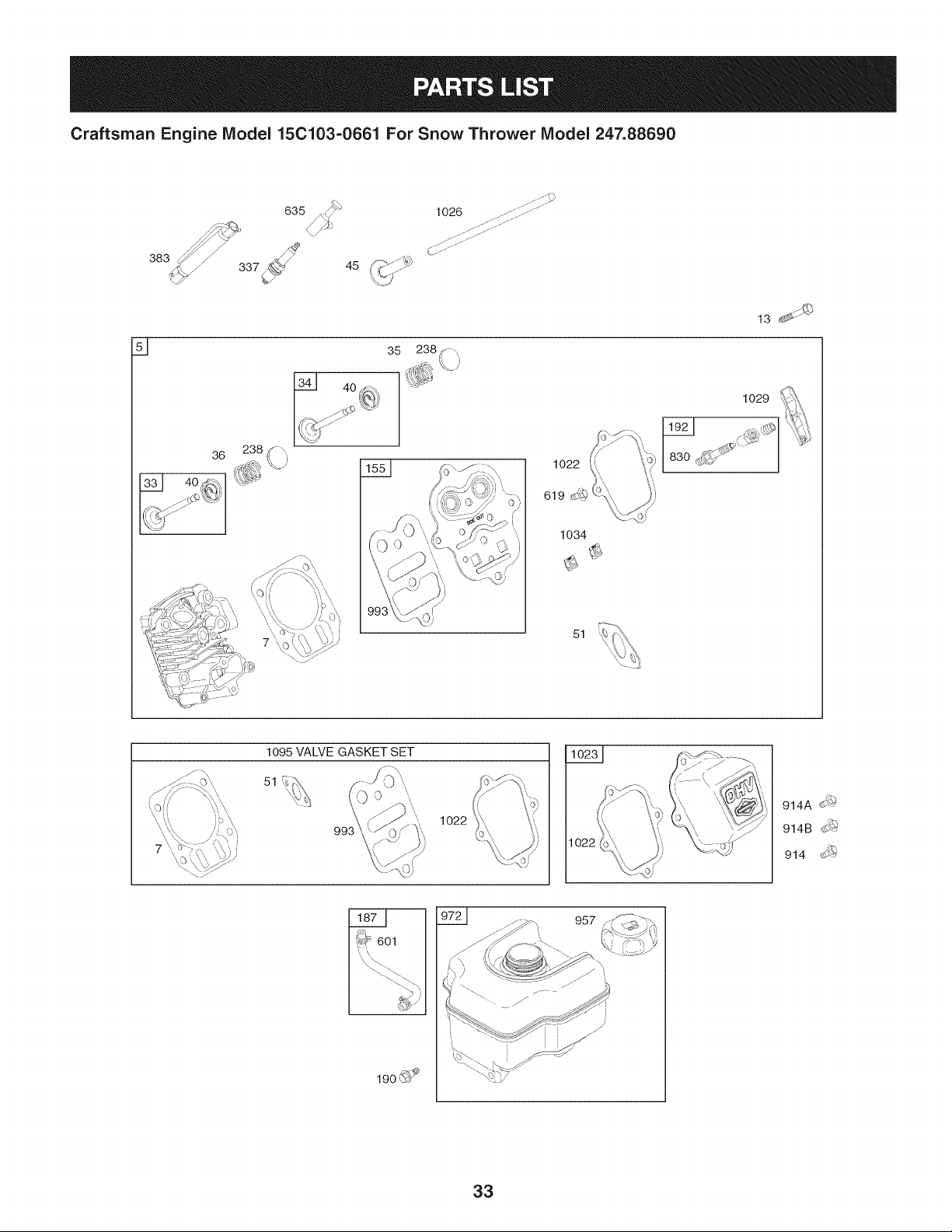
Craftsman Engine Model 15C103-0661 For Snow Thrower Model 247.88690
383
635
45
1026 ......._:[: .......
36
F-_ _
238
1034
1029
51
1095 VALVE GASKET SET
51 _-ii_L_
993
1022
1022
914
601
19o_?
957
33
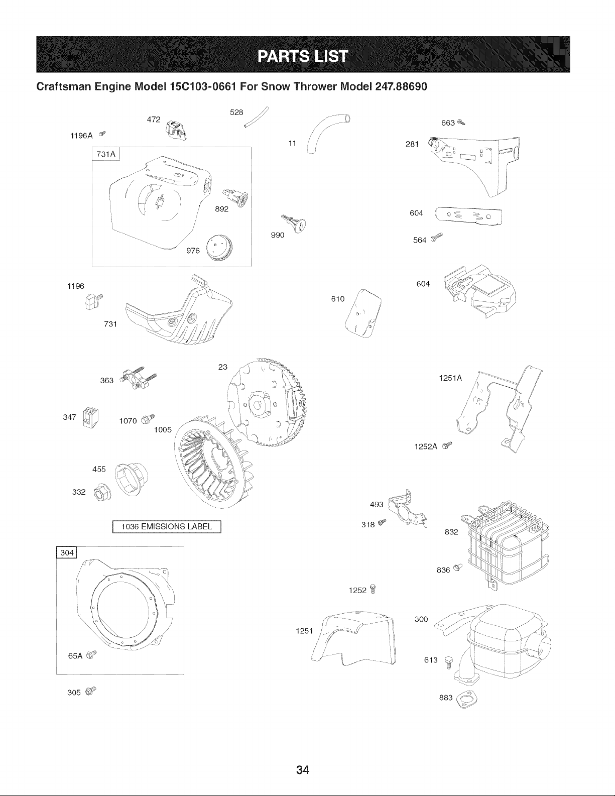
Craftsman Engine Model 15C103=0661 For Snow Thrower Model 247.88690
528
472
1196A ¢_
11 i'
663_%
281
\
",\\
604 =:_ o _ _, o
990 564 I_
1196
x
731 \ ....
610
/
604
347
1070 (_
1005 /
/
23
1251A
1252A _'>
455
332
1036 EMISSIONS LABEL ]
65A_
1252
300
305 _>
883
34
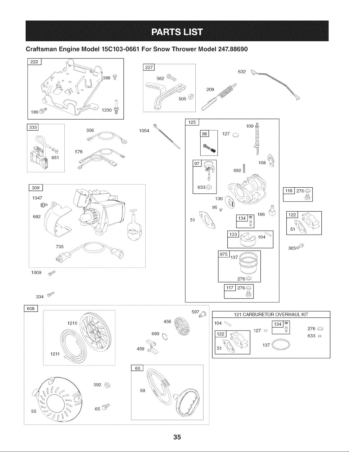
Craftsman Engine IViodel 15C103-0661 For Snow Thrower IViodel 247.88690
578
851
\
1347
682
735
1009
562 '_'*_,
334 _>
1o54
632
209
51
108
186
13___._ _- lo4_
4,.YA_9
975_ _
137 _I[_S .... '_I
%.::::cj
276 q_
t ....
276 _,_
365_ _'_
55
'_,_
,, ,__
.....,!_,_, ........,...,,,,_.___
592 _
459
58
104 _
121 CARBURETOR OVERHAUL KIT
127 _ _-8-J_ I 276 (_
633 _
137
35
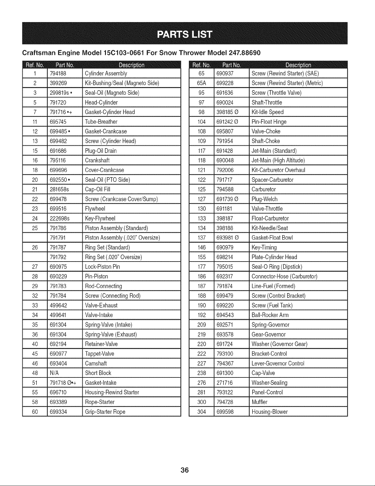
Craftsman Engine Model 15C103=0661 For Snow Thrower Model 247.88690
D = O
794188 CylinderAssembly
2 399269 Kit-Bushing/Seal(MagnetoSide)
3 299819s• Seal-Oil(MagnetoSide)
5 791720 Head-Cylinder
7 791716.+ Gasket-CylinderHead
11 695745 Tube-Breather
12 699485• Gasket-Crankcase
13 699482 Screw(CylinderHead)
15 691686 Plug-OilDrain
16 795116 Crankshaft
18 699696 Cover-Crankcase
20 692550. Seal-Oil(PTOSide)
21 281658s Cap-OilFill
22 699478 Screw(CrankcaseCover/Sump)
23 699516 Flywheel
24 222698s Key-Flywheel
25 791786 PistonAssembly(Standard)
791791 PistonAssembly(.020"Oversize)
26 791787 RingSet (Standard)
791792 RingSet (.020"Oversize)
27 690975 Lock-PistonPin
28 690229 Pin-Piston
29 791783 Rod-Connecting
32 791784 Screw(ConnectingRod)
33 499642 Valve-Exhaust
34 499641 Valve-Intake
35 691304 Spring-Valve(Intake)
36 691304 Spring-Valve(Exhaust)
40 692194 Retainer-Valve
45 690977 Tappet-Valve
46 693404 Camshaft
48 N/A ShortBlock
51 7917180.+ Gasket-Intake
55 696710 Housing-RewindStarter
58 693389 Rope-Starter
60 699334 Grip-StarterRope
D = O
690937 Screw(RewindStarter)(SAE)
65A 699228 Screw(RewindStarter)(Metric)
95 691636 Screw(ThrottleValve)
97 690024 Shaft-Throttle
98 3981850 Kit-IdleSpeed
104 6912420 Pin-FloatHinge
108 695807 Valve-Choke
109 791954 Shaft-Choke
117 691428 Jet-Main(Standard)
118 690048 Jet-Main(HighAltitude)
121 792006 Kit-CarburetorOverhaul
122 791717 Spacer-Carburetor
125 794588 Carburetor
127 6917390 Plug-Welch
130 691181 Valve-Throttle
133 398187 Float-Carburetor
134 398188 Kit-Needle/Seat
137 6939810 Gasket-FloatBowl
146 690979 Key-Timing
155 698214 Plate-CylinderHead
177 795015 Seal-ORing(Dipstick)
186 692317 Connector-Hose(Carburetor)
187 791874 Line-Fuel(Formed)
188 699479 Screw(ControlBracket)
190 699220 Screw(FuelTank)
192 694543 Bali-RockerArm
209 692571 Spring-Governor
219 693578 Gear-Governor
220 691724 Washer(GovernorGear)
222 793100 Bracket-Control
227 794367 Lever-GovernorControl
238 691300 Cap-Valve
276 271716 Washer-Sealing
281 793122 Panel-Control
L
300 794728 Muffler
304 699598 Housing-Blower
36
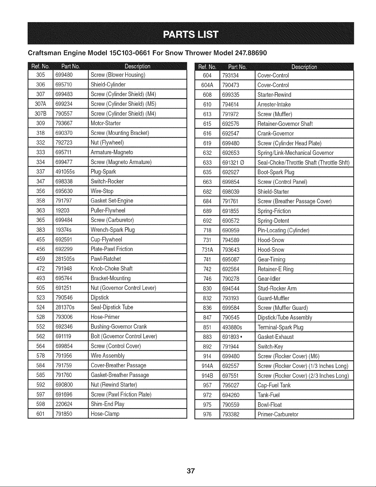
Craftsman Engine IViodel 15C103-0661 For Snow Thrower IViodel 247.88690
306
307
307A 699234 Screw(CylinderShield)(M5)
307B 790557 Screw(CylinderShield)(M4)
309 793667 Motor-Starter
318 690370 Screw(MountingBracket)
332 792723 Nut(Flywheel)
333 695711 Armature-Magneto
334 699477 Screw(MagnetoArmature)
337 491055s Plug-Spark
699480 Screw(BlowerHousing)
695710 Shield-Cylinder
699483 Screw(CylinderShield)(M4)
347 698338 Switch-Rocker
356 695630 Wire-Stop
358 791797 GasketSet-Engine
363 19203 Puller-Flywheel
365 699484 Screw(Carburetor)
383 19374s Wrench-SparkPlug
455 692591 Cup-Flywheel
456 692299 Plate-PawlFriction
459
472
493
5O5
523
524
528
552
562
564
578
584
585
592
597
598
601
281505s PawI-Ratchet
791948 Knob-ChokeShaft
695744 Bracket-Mounting
691251 Nut(GovernorControlLever)
790546 Dipstick
281370s Seal-DipstickTube
793006 Hose-Primer
692346 Bushing-GovernorCrank
691119 Bolt(GovernorControlLever)
699854 Screw(ControlCover)
791956 WireAssembly
791759 Cover-BreatherPassage
791760 Gasket-BreatherPassage
690800 Nut(RewindStarter)
691696 Screw(PawlFrictionPlate)
220624 Shim-EndPlay
791850 Hose-Clamp
D = O O
793134 Cover-Control
604A 790473 Cover-Control
608 699335 Starter-Rewind
610 794614 Arrester-lntake
613 791972 Screw(Muffler)
615 692576 Retainer-GovernorShaft
616 692547
619 699480
632 692653
633 691321 0
635 692927
663 699854
682 698039
684 791761
Crank-Governor
Screw(CylinderHeadPlate)
Spring/Link-MechanicalGovernor
Seal-Choke/ThrottleShaft(ThrottleShft)
Boot-SparkPlug
Screw(ControlPanel)
Shield-Starter
Screw(BreatherPassageCover)
689
691855 Spring-Friction
692 690572 Spring-Detent
718 690959 Pin-Locating(Cylinder)
731 794589 Hood-Snow
731A 793643 Hood-Snow
741 695087 Gear-Timing
742 692564 Retainer-ERing
746 790278 Gear-Idler
830 694544 Stud-RockerArm
832 793193 Guard-Muffler
836 699584 Screw(MufflerGuard)
847 790545 Dipstick/TubeAssembly
851 493880s Terminal-SparkPlug
883 691893• Gasket-Exhaust
892 791944 Switch-Key
914 699480 Screw(RockerCover)(M6)
914A 692557 Screw(RockerCover)(1/3 InchesLong)
914B 697551 Screw(RockerCover)(2/3 InchesLong)
957 795027 Cap-FuelTank
972 694260 Tank-Fuel
975 790559 Bowl-Float
976 793382 Primer-Carburetor
37
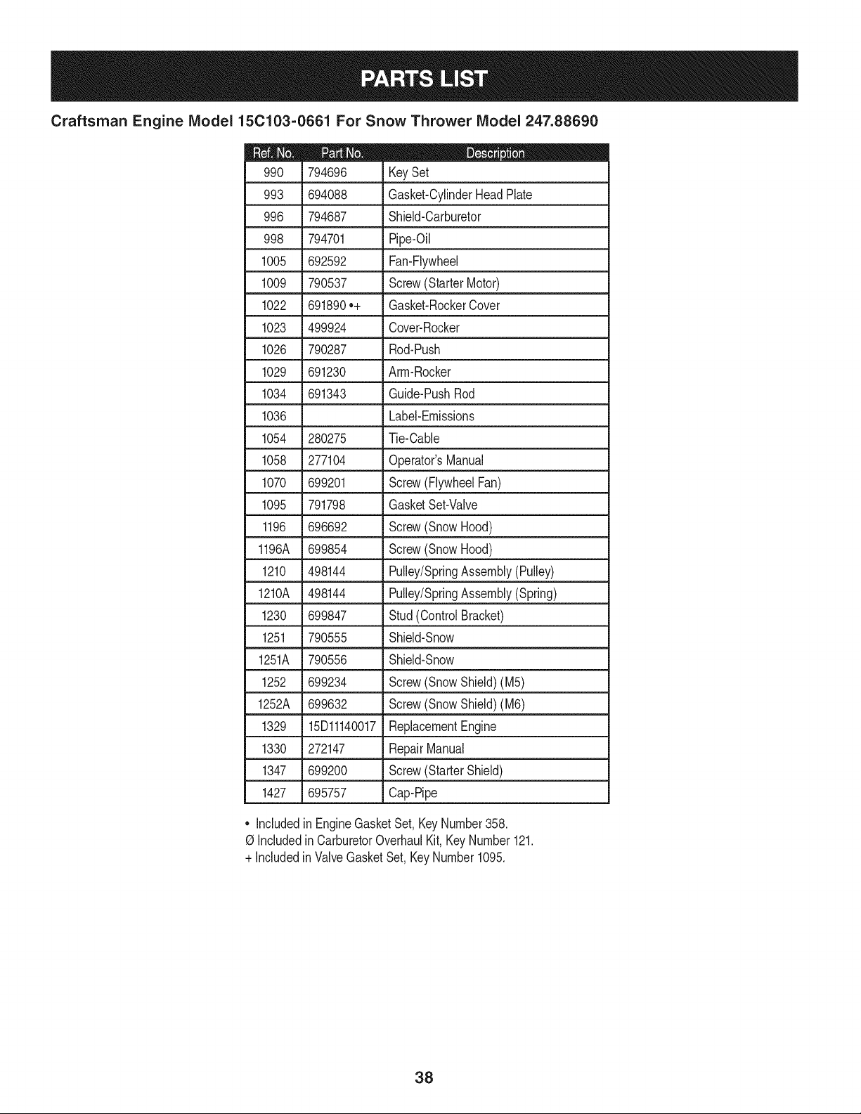
Craftsman Engine Model 15C103-0661 For Snow Thrower Model 247.88690
794696 KeySet
993 694088 Gasket-CylinderHeadPlate
996 794687 Shield-Carburetor
998 794701 Pipe-Oil
1005 692592 Fan-Flywheel
1009 790537 Screw(StarterMotor)
1022 691890o+ Gasket-RockerCover
1023 499924 Cover-Rocker
1026 790287 Rod-Push
1029 691230 Arm-Rocker
1034 691343 Guide-PushRod
1036 Label-Emissions
1054 280275 Tie-Cable
1058 _ 277104 _ Operator'sManual
1070 699201 Screw(FlywheelFan)
1095 791798 GasketSet-Valve
1196 696692 Screw(SnowHood)
1196A 699854 Screw(SnowHood)
1210 498144 Pulley/SpringAssembly(Pulley)
1210A 498144 Pulley/SpringAssembly(Spring)
1230 699847 Stud(ControlBracket)
1251 790555 Shield-Snow
1251A 790556 Shield-Snow
1252 699234 Screw(SnowShield)(M5)
1252A _ 699632 _ Screw(SnowShield)(M6)
1329 15Dl1140017 ReplacementEngine
1330 272147 RepairManual
1347 699200 Screw(StarterShield)
1427 695757 Cap-Pipe
Includedin EngineGasketSet,KeyNumber358.
0 Includedin CarburetorOverhaulKit, KeyNumber121.
+ IncludedinValveGasketSet,KeyNumber1095.
38

39
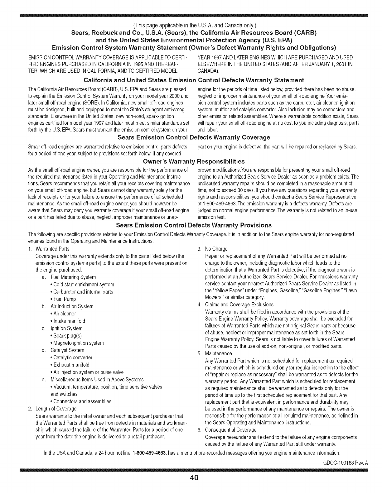
(Thispageapplicablein the U.S.A.and Canadaonly.)
Sears, Roebuck and Co., U.S.A. (Sears), the California Air Resources Board (CARD)
and the United States Environmental Protection Agency (U.S. EPA)
Emission Control System Warranty Statement (Owner's Defect Warranty Rights and Obligations)
EMISSIONCONTROLWARRANTYCOVERAGEISAPPLICABLETO CERTI-
FIEDENGINESPURCHASEDINCALIFORNIAIN 1995ANDTHEREAF-
TER,WHICHARE USEDINCALIFORNIA,ANDTO CERTIFIEDMODEL
California and United States Emission
The CaliforniaAir ResourcesBoard(CARD),U.S.EPAand Searsare pleased
to explainthe EmissionControlSystemWarrantyon your modelyear2000and
latersmalloff-roadengine(SORE).In California,newsmall off-roadengines
mustbe designed,builtand equippedto meetthe State'sstringentanti-smog
standards.Elsewherein theUnitedStates, newnon-road,spark-ignition
enginescertifiedfor modelyear 1997and latermustmeetsimilar standardsset
forth bythe U.S.EPA.Sears mustwarrantthe emissioncontrol systemonyour
YEAR 1997AND LATERENGINESWHICHARE PURCHASEDAND USED
ELSEWHEREIN THE UNITEDSTATES(ANDAFTERJANUARY1,2001 IN
CANADA).
Control Defects Warranty Statement
enginefor the periodsoftime listedbelow,providedtherehasbeen noabuse,
neglector impropermaintenanceof your smalloff-roadengine.Youremis-
sion controlsystemincludespartssuch as thecarburetor,air cleaner,ignition
system,mufflerand catalyticconverter.Also includedmaybeconnectorsand
otheremissionrelatedassemblies.Wherea warrantableconditionexists,Sears
will repairyour smalloff-roadengineat no costto you includingdiagnosis,parts
and labor.
Sears Emission Control Defects Warranty Coverage
Smalloff-roadenginesarewarrantedrelativeto emissioncontrolpartsdefects
fora period of one year,subjectto provisionsset forth below.Ifany covered
Owner's Warranty
Asthe smalloff-roadengineowner,you are responsiblefor theperformanceof
therequiredmaintenancelistedin yourOperatingand MaintenanceInstruc-
tions.Searsrecommendsthatyouretainallyourreceiptscoveringmaintenance
on yoursmalloff-roadengine,butSears cannotdenywarrantysolelyfor the
lackof receiptsorfor yourfailureto ensurethe performanceof all scheduled
maintenance.As the smalloff-roadengineowner,you shouldhoweverbe
awarethat Searsmay denyyou warrantycoverageif your smalloff-roadengine
ora part hasfaileddueto abuse,neglect,impropermaintenanceor unap-
parton yourengineis defective,the part willbe repairedorreplacedbySears.
Responsibilities
provedmodifications.Youare responsiblefor presentingyour smalloff-road
engineto an AuthorizedSearsServiceDealeras soonas a problemexists.The
undisputedwarrantyrepairsshouldbe completedina reasonableamountof
time,not to exceed30 days. Ifyou haveanyquestionsregardingyourwarranty
rightsand responsibilities,you shouldcontacta SearsService Representative
at 1-800-469-4663.The emissionwarrantyis a defectswarranty.Defectsare
judgedon normalengineperformance.Thewarrantyis not relatedto an in-use
emissiontest.
Sears Emission Control Defects Warranty Provisions
ThefollowingarespecificprovisionsrelativetoyourEmissionControlDefectsWarrantyCoverage.ItisinadditiontotheSearsenginewarrantyfornon-regulated
enginesfoundin theOperatingand MaintenanceInstructions.
1. WarrantedParts
Coverageunderthis warrantyextendsonly to the parts listedbelow (the
emissioncontrolsystemsparts)to the extentthese partswere presenton
the engine purchased.
a. FuelMeteringSystem
• Cold start enrichmentsystem
• Carburetorand internalparts
• FuelPump
b. Air lnduction System
• Air cleaner
• Intakemanifold
c. IgnitionSystem
• Spark plug(s)
• Magnetoignitionsystem
d. CatalystSystem
• Catalyticconverter
• Exhaustmanifold
• Air injectionsystemor pulsevalve
e. MiscellaneousItemsUsedin AboveSystems
• Vacuum,temperature,position,timesensitivevalves
andswitches
• Connectorsandassemblies
2. Lengthof Coverage
Searswarrantsto the initialownerand eachsubsequentpurchaserthat
the WarrantedParts shallbe free from defects in materialsandworkman-
shipwhich causedthefailure of the WarrantedPartsfor a periodof one
yearfrom the datethe engineis deliveredto a retailpurchaser.
3. NoCharge
Repairor replacementof anyWarrantedPartwill be performedat no
chargeto the owner,includingdiagnosticlabor whichleads to the
determinationthata WarrantedPartis defective,if the diagnosticworkis
performedat an AuthorizedSears ServiceDealer.For emissionswarranty
servicecontact yournearestAuthorizedSears ServiceDealeras listed in
the "YellowPages"under"Engines,Gasoline,""GasolineEngines,""Lawn
Mowers,"orsimilarcategory.
4. Claimsand CoverageExclusions
Warrantyclaimsshall be filed in accordancewiththe provisionsof the
Sears EngineWarrantyPolicy.Warrantycoverageshall be excludedfor
failuresof WarrantedPartswhichare not original Sears partsor because
of abuse,neglector impropermaintenanceas setforth inthe Sears
EngineWarrantyPolicy.Sears is notliableto coverfailuresof Warranted
Partscausedby theuse of add-on, non-original,or modifiedparts.
5. Maintenance
Any WarrantedPart whichis not scheduledfor replacementas required
maintenanceor whichis scheduledonly for regularinspectionto the effect
of "repairor replaceas necessary"shallbe warrantedasto defectsfor the
warrantyperiod.Any WarrantedPartwhich is scheduledfor replacement
as requiredmaintenanceshallbe warrantedasto defectsonly forthe
periodof time upto the firstscheduledreplacementfor that part. Any
replacementpart that is equivalentin performanceand durabilitymay
be usedin the performanceof anymaintenanceor repairs.The owneris
responsibleforthe performanceof all requiredmaintenance,as definedin
the SearsOperatingand MaintenanceInstructions.
6. ConsequentialCoverage
Coveragehereundershallextendto thefailure of anyenginecomponents
caused bythe failureof any WarrantedPartstill underwarranty.
Inthe USAandCanada,a 24 hour hot line, 1-800-469-4663,has a menuof pre-recordedmessagesofferingyou enginemaintenanceinformation.
GDOC-100188Rev.A
40
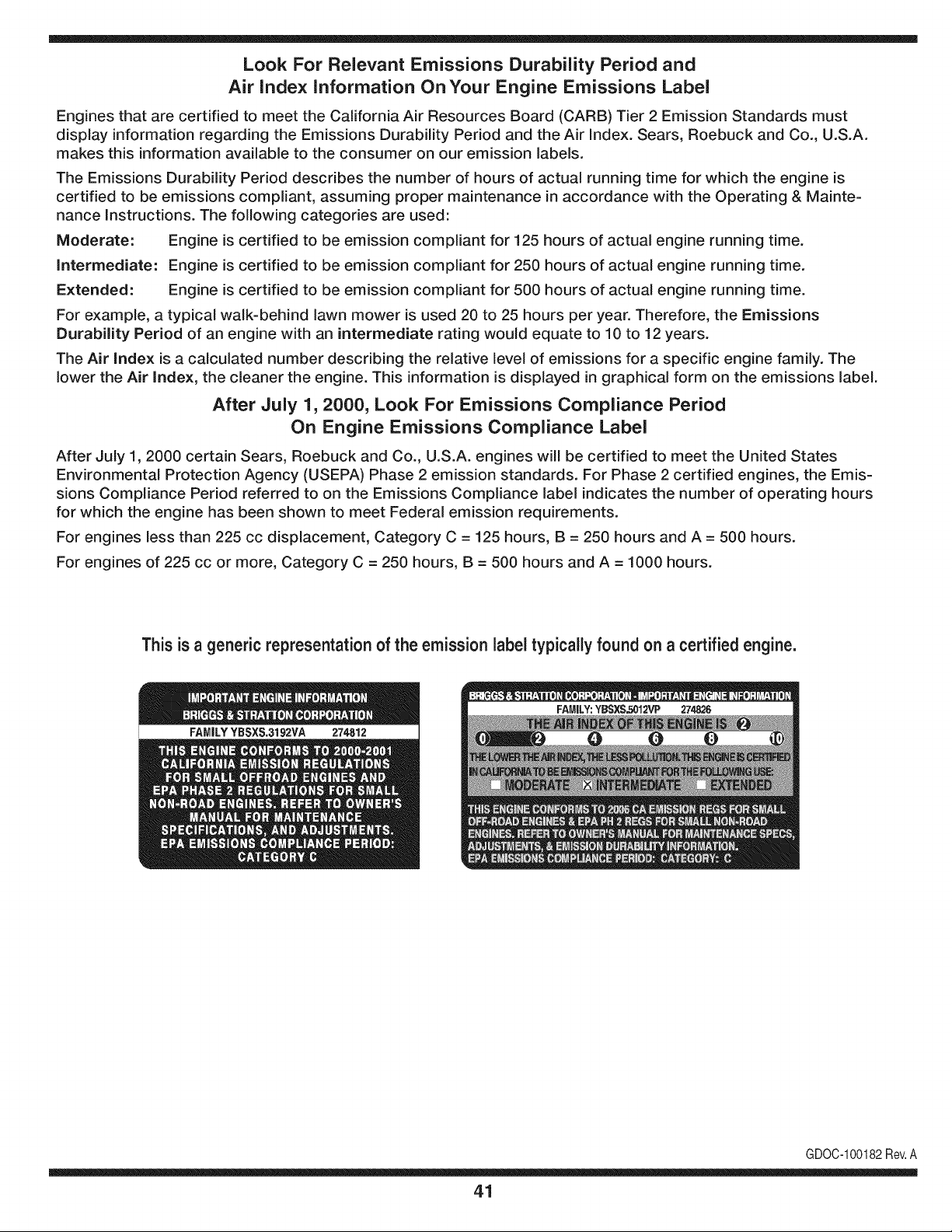
Look For Relevant Emissions Durability Period and
Air index information On Your Engine Emissions Label
Engines that are certified to meet the California Air Resources Board (CARB) Tier 2 Emission Standards must
display information regarding the Emissions Durability Period and the Air Index. Sears, Roebuck and Co., U.S.A.
makes this information available to the consumer on our emission labels.
The Emissions Durability Period describes the number of hours of actual running time for which the engine is
certified to be emissions compliant, assuming proper maintenance in accordance with the Operating & Mainte-
nance Instructions. The following categories are used:
Moderate: Engine is certified to be emission compliant for 125 hours of actual engine running time.
Intermediate: Engine is certified to be emission compliant for 250 hours of actual engine running time.
Extended: Engine is certified to be emission compliant for 500 hours of actual engine running time.
For example, a typical walk-behind lawn mower is used 20 to 25 hours per year. Therefore, the Emissions
Durability Period of an engine with an intermediate rating would equate to 10 to 12 years.
The Air Index is a calculated number describing the relative level of emissions for a specific engine family. The
lower the Air Index, the cleaner the engine. This information is displayed in graphical form on the emissions label.
After July 1,2000, Look For Emissions Compliance Period
On Engine Emissions Compliance Label
After July 1, 2000 certain Sears, Roebuck and Co., U.S.A. engines will be certified to meet the United States
Environmental Protection Agency (USEPA) Phase 2 emission standards. For Phase 2 certified engines, the Emis-
sions Compliance Period referred to on the Emissions Compliance label indicates the number of operating hours
for which the engine has been shown to meet Federal emission requirements.
For engines less than 225 cc displacement, Category C = 125 hours, B = 250 hours and A = 500 hours.
For engines of 225 cc or more, Category C = 250 hours, B = 500 hours and A = 1000 hours.
This is a generic representation of the emission label typically found on a certified engine.
FAMILYYBSXS.3192VA 274812
GDOC-100182Rev.A
41
Congratulationson makinga smartpurchase.YournewCraftsman@
productis designedand manufacturedfor yearsof dependableopera-
tion.But likeall products,it mayrequirerepairfromtimeto time.That's
whenhavinga RepairProtectionAgreementcansave youmoneyand
aggravation.
Here'swhatthe RepairProtectionAgreement*includes:
* Expert service byour 10,000professionalrepairspecialists
o Unlimitedserviceand no chargefor partsand laboron all
coveredrepairs
o Product replacementup to $1500if yourcoveredproductcan't be
fixed
• Discountof 10%from regularprice of serviceand relatedinstalled
partsnotcoveredby theagreement;also,10%off regularpriceof
preventivemaintenancecheck
• Fast help by phone- we call it RapidResolution- phonesupport
froma Searsrepresentative.Thinkof usas a "talkingowner's
manual."
Onceyou purchasethe Agreement,a simplephonecall is all thatit
takesfor youto scheduleservice.Youcan call anytimedayor night,or
schedulea serviceappointmentonline.
The RepairProtectionAgreementis a risk-freepurchase.If youcancel
for any reasonduringthe productwarrantyperiod,wewill providea full
refund.Or,a proratedrefundanytimeafterthe productwarrantyperiod
expires.Purchaseyour RepairProtectionAgreementtoday!
Somelimitationsand exclusionsapply. For pricesand additional
informationin the U.S.A.call 1-800-827-6655.
*Coverage inCanadavaries on some items. Forfull details call
Sears Canadaat 1-800-361-6665.
Sears Installation Service
ForSearsprofessionalinstallationof homeappliances,garagedoor
openers,waterheaters,and othermajorhomeitems,in the U.S.A.or
Canadacall 1-800-4-MY-HOME®.
42
Declaraci6n de garantia ............................ Pagina 43
Practicas operaci6n seguras ..................... Pagina 44
Montaje ...................................................... Pagina 48
Operaci6n .................................................. Pagina 52
Servicio y Mantenimiento .......................... Pagina 56
Almacenamiento fuera de temporada ....... Pagina 64
Soluci6n de problemas .............................. Pagina 65
Acuerdo de protecci6n para reparaciones .... Pagina 69
Etiquetas de seguridad .............................. Pagina 7
Lista de piezas ........................................... Pagina 26
NOmero de servicio ................................... Cubierta
posterior
GARANTiA LIMITADA CRAFTSMAN
Dos Ahos en Lanzador de Nieve
Cuandohechofuncionary mantenidosegQntodaslasinstruccionessuministradas,si este lanzadorde nievefalla debidoa undefectoen mate-
rialo habilidaddentrode dosa_osde la fechao compra,Ilame1-800-4MYHOMEhacerlosarreglosparareparaci6nlibre.
Estagaranfias61otendr_validezdurante90 dias si esteproductose utilizaen cualquiermomentoparafinescomercialeso de alquiler.
Duranteel primera_o de la compra,no habr_ningOnprecioparael serviciode garanfiaen sucasa. Parasu conveniencia,en de casael servicio
degaranfiatodaviaestar_disponibledespu_sdel primera_ode la compra,pero un preciode viaje se aplicar& Estepreciosera renunciado
si ustedtransportaal lanzadorde nievea unaposici6nde bajadade Artesanoautorizada.Parala posici6nautorizadam_scercana,Ilame
1-800-4-MY-HOME®.
Esta garantiacubreSOLO defectos en material y habilidad.Sears no pagar_para:
• Losarficulosprescindiblesquese hacenIlevadospuestosduranteel uso normal,incluso,perono limitadosparapatinarzapatos,platode
afeitado,esquilanalfileres,buj[a,filtro de aire,cinturones,y filtro del aceite.
• Revisi6nde mantenimientoest_ndar,cambiosde aceite,o puestasa punto.
• Reemplazodeneum_ticoo reparaci6ncausadaporpinchazosdesdefuerade objetos,como u_as,espinas,tocones,ocristal.
• Neum_ticoo reemplazode ruedao reparaci6nque resultade ropanormal,accidente,u operaci6nimpropiao mantenimiento.
• Las reparacionesnecesariasdebidoal abusode operador,inclusoperono limitadoparada_arcausadoafectandoobjetosquedoblanel
marcoo el cigOe_al,o el sobreexcesode velocidaddel motor.
• Reparacionesnecesariasdebidoa negligenciadel operador,incluyendoentre otros,da_osmec_nicoy el_ctricoocasionadoporun
almacenamientonoapropiado,falla por el usode aceitedegradoy/o cantidadno apropiadao fallapor no dar mantenimientoal equipode
acuerdocon las instruccionescontenidasen el manualdel operador.
• Limpiezao reparacionesal motor(sistemadecombustible)provocadaspor un combustiblecontaminadouoxidado(viejo).En general,el
combustibledebeutilizarseen unperbdo no mayorde 30 d[as a partirde su adquisici6n.
• Elempejoramientonormaly la ropade losfines exteriores,o productoetiquetanel reemplazo.
Estagaranfias61otendrAvalidezmientrasel productose utiliceen los EstadosUnidos.
Estagaranfiale otorgaderechoslegalesespedficos,pero ustedpodr[agozarde otrosderechosen raz6nde su lugarde residencia.
Sears, Roebuck and Co., HoffmanEstates, IL 60179
Tipode aceitedelmotor:
Capacidaddeaceitedel motor:
Capacidaddecombustible:
Bujfas:
Separaci6nde lasbujias:
SAE 5W-30
20 onzas
3 cuartos
Champion® RC12YC
.030"
N_merode modelo ..........................................................
N_merode serie ..............................................................
Fechade compra .............................................................
Registrearriba el nOmerodel modelo,elnOmerode seriey lafecha
decompra
© Sears Brands,LLC
43
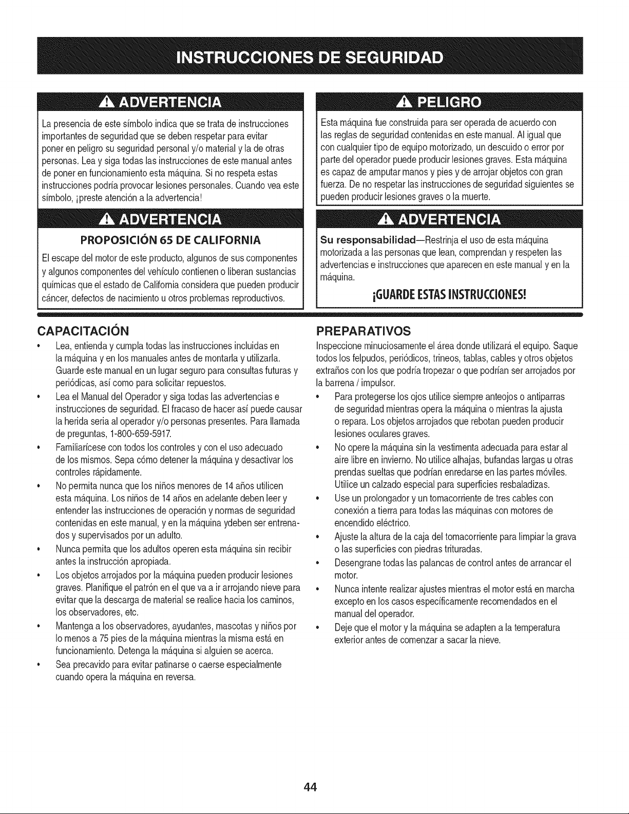
Lapresenciade este sirnboloindicaque setrata de instrucciones
irnportantesde seguridadque se deben respetarpara evitar
ponerenpeligrosu seguridadpersonaly/o materialy la de otras
personas.Lea y sigatodas lasinstruccionesdeestemanualantes
de poneren funcionarnientoesta rn_.quina.Si no respetaestas
instruccionespodria provocarlesionespersonales.Cuandoveaeste
sirnbolo,ipresteatenci6na la advertencia!
PROPOSICI6N 65 DE CALIFORNIA
Elescapedel motorde esteproducto,algunosde sus cornponentes
y algunoscornponentesdelvehiculocontieneno liberansustancias
quirnicasqueelestadode Californiaconsideraque puedenproducir
c_.ncer,defectosde nacirnientou otros problernasreproductivos.
Estarn_.quinarueconstruidaparaseroperadade acuerdocon
las reglasde seguridadcontenidasenestemanual.AI igualque
concualquiertipo deequipornotorizado,undescuidoo errorpor
partedel operadorpuedeproducirlesionesgraves.Estarn_.quina
es capazde arnputarrnanosy piesy de arrojarobjetoscon gran
fuerza.De norespetarlas instruccionesde seguridadsiguientesse
puedenproducirlesionesgraveso la rnuerte.
Su responsabilidad--Restrinja el usode estarn_.quina
rnotorizadaa las personasque lean,cornprendany respetenlas
advertenciase instruccionesqueaparecenen este manualy en la
rn_.quina.
iGUARDEESTASINSTRUCCIONES!
CAPACITACION
• Lea,entienday curnplatodaslas instruccionesincluidasen
la rn_.quinay enlos rnanualesantesde rnontarlay utilizarla.
Guardeestemanualen un lugarseguropara consultasfuturasy
peri6dicas,asi cornopara solicitarrepuestos.
• Leael ManualdelOperadory sigatodas las advertenciase
instruccionesdeseguridad.El fracasode hacerasi puedecausar
la heridaseriaal operadory/o personaspresentes.Para Ilarnada
de preguntas,1-800-659-5917.
• Farniliaricesecontodos los controlesy con el usoadecuado
de losrnisrnos.Sepac6rnodetenerla rn_.quinay desactivarlos
controlesr_.pidarnente.
• No perrnitanuncaque losni_os rnenoresde 14a_osutilicen
estarn_.quina.Los ni_osde 14a_osenadelantedebenleer y
entenderlas instruccionesde operaci6ny norrnasde seguridad
contenidasen estemanual,yen la rn_.quinaydebenserentrena-
dosy supervisadospor unadulto.
• Nuncaperrnitaquelos adultosoperenestarn_.quinasin recibir
antesla instrucci6napropiada.
• Losobjetosarrojadosporla rn_.quinapuedenproducirlesiones
graves.Planifiqueel patr6nen el queva air arrojandonievepara
evitarquela descargade materialse realicehacialos carninos,
los observadores,etc.
• Mantengaa los observadores,ayudantes,rnascotasy ni_ospor
Io rnenosa 75piesde la rn_.quinarnientrasla rnisrnaest,.en
funcionarniento.Detengala rn_.quinasialguien se acerca.
• Seaprecavidopara evitarpatinarseo caerseespecialrnente
cuandoopera la rn_.quinaen reversa.
PREPARATIVOS
Inspeccionerninuciosarnenteel _.readondeutilizar_,el equipo.Saque
todoslos felpudos,peri6dicos,trineos,tablas,cables y otrosobjetos
extra_oscon los que podriatropezaro quepodrianser arrojadospor
la barrena/ irnpulsor.
• Paraprotegerselosojos utilice siernpreanteojoso antiparras
de seguridadrnientrasoperala rn_.quinao rnientrasla ajusta
o repara.Losobjetosarrojadosque rebotanpuedenproducir
lesionesocularesgraves.
• Noopere la rn_.quinasin la vestirnentaadecuadaparaestaral
aire libreen invierno.No utilicealhajas,bufandaslargasu otras
prendassueltasquepodrianenredarseen las partes rn6viles.
Utiliceun calzadoespecialparasuperficiesresbaladizas.
• Useun prolongadory untornacorrientede tres cablescon
conexi6natierra paratodaslas rn_.quinascon rnotoresde
encendidoel_ctrico.
• Ajustela alturade lacaja deltornacorrienteparalirnpiarla grava
o las superficiescon piedrastrituradas.
• Desengranetodas las palancasde controlantesde arrancarel
motor.
• Nuncaintenterealizarajustesrnientrasel motorest,.enrnarcha
exceptoen los casosespedficarnenterecornendadosen el
manualdel operador.
• Dejequeel motory la rn_.quinaseadaptena laternperatura
exteriorantesdecornenzara sacarla nieve.
44
Manejo seguro de la gasolina
Paraevitarlesionespersonaleso daSosmaterialestengamucho
cuidadocuandotrabajecon gasolina.Lagasolinaes sumamente
infiamabley susvaporespuedencausarexplosiones,Si se derrama
gasolinaencimao sobrela ropase puedelesionargravementeya que
se puedeincendiar,L&vesela piely c&mbiesede ropade inmediato,
• Utilices61olos recipientesparagasolinaautorizados.
• Apaguetodoslos cigarrillos,cigarros,pipasy otras fuentesde
combusti6n.
• Nuncacarguecombustibleen la m_.quinaen unespado cerrado,
• Nuncasaquelatapa delcombustibleni agreguecombustible
mientrasel motorest&calienteo en marcha.
• Dejeque el motorse enfriepor Iomenosdos minutosantesde
volvera cargarcombustible,
• NuncaIleneenexcesoeldep6sitodecombustible.Lleneel
tanquea no m_.sde 1/2pulgadapordebajode la basedel cuello
deIlenadodejandoespacioparaladilataddn delcombustible,
• Vuelvaa colocarla tapade lagasolinay ajQstelabien,
• Limpieel combustibleque se hayaderramadosobreel motory el
equipo.Trasladela m_.quinaa otra zona, Espere5 minutosantes
deencenderel motor,
• Nuncaalmacenela m_.quinao el redpientede combustibleen
unespaciocerradodonde hayafuego,chispaso luz piloto(por
ejemplo,hornos,calentadoresde agua,calefactores,secadores
de ropa,etc.),
Dejeque la m&quinase enfriepor Io menos5 minutosantesde
guardarla,
• NuncaIlenelos recipientesenel interiorde un vehiculoo camidn
o cajade remolquecon recubrimientospl&sficos.Coloque
siemprelos redpientesenel pisoy lejosdel vehiculoantesde
Ilenarlos.
• Sies posiNe,retireel equipoa gasolinadelcami6no remolque
y II_neloen el suelo,Siestono es posiNe,Ileneel equipoen un
remolqueconcontenedorport_.til,en vezdedesdeuna boquilla
dispensadoradegasolina.
• Mantengala boquilladispensadoraen contactocon el hordedel
depdsitode combustibleo con la aberturadel recipienteen todo
momento,hastaterminarlacarga.No utiliceundisposifivode
apertura/derrede boquilh,
FUNCIONAMIENTO
• No pongalas manoso los piescercadelas piezasrotatorias,
enla cajade la barrena/ impulsoro en el montajedel canalde
descarga,Hacercontactocon piezasgiratoriaspuederesultaren
la amputacidndemanoso pies.
• La palancadecontrolde la barrena/ impulsores undisposifivo
deseguridad,Nuncaevitesu funcionamiento,De hacerlola
operad6ndela m_.quinaes riesgosay puedeocasionarlesiones,
• Las palancasde control debenfuncionarbienen ambasdirec-
clonesy regresarautom_.ticamentea la posicidnde desengrane
cuandose las suelta,
Nuncaoperela m_.quinasi falta un montajedel canalo si el
mismoest,. da_ado.Mantengatodoslosdispositivosde seguri-
daden su lugary en funcionamiento.
• Nuncaenciendael motoren espacioscerradoso en unazona
con pocaventilaci6n.El escapedel motorcontienemon6xidode
carbono,ungas inodoroy letal.
• Noutilice la m_.quinabajola influenciadel alcoholo las drogas.
• El silenciadory el motorse calientany puedencausarquemadu-
ras.Nolos toque.Mantengaa los ni_osalejados.
• Seasumamenteprecavidocuandooperelam_.quinasobreuna
superficiecon gravao cuandola cruce.Mant_ngasealerta porsi
sepresentanpeligrosocultoso tr_.nsito.
• Tengacuidadocuandocambiede direcci6no cuandooperela
m_.quinaen pendientes.
• Planifiqueel patr6nen el que va air arrojandonievepara evitar
que la descargade materialse produzcahacialas ventanas,
lasparedes,losautom6viles,etc.y evitarasi posiblesda_os
materialeso lesionesproducidaspor los rebotes.
• Nuncadirija ladescargahacialos ni_os,los observadoreso las
mascotasni dejequenadiese paredelantede lam_.quina.
• Nosobrecarguela capacidadde la m_.quinatratandode sacarla
nievemuy r_.pidamente.
• Nuncaopere esta m_.quinasin buenavisibilidado iluminaci6n.
Siempredebe estar segurode que est,. bienafirmadoy su-
jetandofirmementelasmanijas.Camine,nuncacorra.
• Cortela corrientea la barrena/ impulsorcuandotransportela
m_.quinao cuandola mismano est,. en uso.
• Nuncaopere la m_.quinaa alta velocidadde desplazamiento
sobresuperficiesresbaladizas.Mirehaciaabajoy haciaatr_.sy
tengacuidadocuandovayamarchaatr_.s.
• Si la m_.quinacomenzaraa vibrarde maneraanormal,detengael
motor,desconecteel cablede la bujiay p6ngalade maneraque
hagamasacontrael motor.Inspeccionela m_.quinaminuciosa-
menteparavet si est,. da_ada.Reparetodos los da_osantesde
encendery operarla m_.quina.
• Desengranetodaslas palancasde controly detengael motor
antesdedejarla posici6nde operaci6n(detr_.sdelas manijas).
Esperea quela barrena/ impulsorse detengaporcompleto
antesdedestaparel montajedel canalo realizarajustese
inspecciones.
• Nuncapongalas manosen lasaberturasde descargao de
recolecci6n.Utilicesiemprelaherramientadelimpiezaquese
adjuntaparadestaparla aberturade descarga.Nodestapeel
montajedelcanal mientrasel motorest,.en funcionamiento.
Antesdedestaparlo,apagueel motory permanezcadetr_.sde las
manijashastaquetodaslas partesm6vilesse hayandetenido.
• Uses61ounionesy accesoriosaprobadosporelfabricante(por
ejemplo,pesasparalas ruedas,cadenasparalos neum_.ticos,
cabinas,etc.).
45
• Paraencenderel motor,jab de lacuerdalentarnentehastaque
sientaresistencb, luegojab r_.pidarnente.El replieguer_.pidode
lacuerdade arranque(tensbn de retroceso)lejalar_,la rnanoy
el brazohaciael motor rn_.sr_.pidodeIo queustedpuedesoltar.
El resultadopuedenserhuesos robs, fracturas,hernatornaso
esguinces.
• Si se presentansituacionesque no est&nprevistasen este
manual,seacuidadosoy useel sentidocornQn.P6ngaseen
contactocon Asistenciaal Clientepara solicitarayuday el
nornbredeldistribuidorde serviciorn_.scercano.
MANTENIMIENTO Y ALMACENAMIENTO
Nuncaalterelos dispositivosde seguridad.Controleperi6dica-
rnenteque funcionencorrectarnente.Rernitasea las secciones
de rnantenirnientoy ajustede estemanual.
• Antesde realizarla lirnpieza,repararo revisarla rn_.quina,
desengranetodaslas palancasde controly detengael motor.
Esperea quela barrena/ irnpulsorsedetengapor cornpleto.
Desconecteel cable de la bujiay p6ngalohaciendornasacontra
el motorparaevitar que se enciendaaccidentalrnente.
Controlefrecuenternentequetodoslospernosy tornillosest_n
bienajustadosparacornprobarquela rn_.quinase encuentra
encondicionessegurasde funcionarniento.Adern_.s,haga una
inspecci6nvisualde larn_.quinapara verificarsi est,.daSada.
• Nocarnbiela configuraci6ndel reguladordel motorni acelere
dernasiadoel rnisrno.El reguladordelmotorcontrolala veloddad
rn_.xirnasegurade funcionarnientodel motor.
• Las placasde raspadoy las zapatasantideslizantesquese
usancon la rn_.quinaquitanievese desgastany se daSan.
Paraprotegersuseguridad,verifiquefrecuenternentetodos los
cornponentesy reernpl&celoss61ocon partesde losfabricantes
deequiposoriginales(OEM)."iEI usode piezasquenocurnplen
con lasespecificacionesdelequipooriginalpuederesultaren
rendirnientoinadecuadoadern_.sde poneren riesgola seguri-
dad!"
Reviselas palancasde controlperi6dicarnenteparaverificar
queengraneny desengranenadecuadarnentey ajOstelossi es
necesario.Consultela secci6nde ajustesde este manualdel
operadorparaobtenerinstrucciones.
Mantengao reernplacelasetiquetasde seguridade instrucciones
segOnseanecesario.
Respetelas norrnasreferentesa la disposici6ncorrectay las
reglarnentacionessobregasolina,aceite,etc. para protegerel
medicarnbiente.
Antesde alrnacenarlarn_.quinaenci_ndalaunosrninutospara
sacarlanieveque hayaquedadoen la rnisrnay paraevitarasi
quese congelela barrena/ irnpulsor.
• SegOnlaCornisi6nde Seguridadde Productosparael Consu-
rnidorde los EstadosUnidos(CPSC)y la Agenciade Protecci6n
Arnbientalde los EstadosUnidos(EPA),esteproductotieneuna
vida Qtilmediade siete (7) a_os,6 60 horasde funcionarniento.
AI finalizarla vidaOtilmedia,adquieraunarn_.quinanuevao
hagainspeccionaranualrnente_stapor undistribuidordeservicio
autorizadoparacerciorarsede que todoslos sisternasrnec_.nicos
y deseguridadfuncionancorrectarnentey notienenexcesivo
desgaste.SinoIo hace,puedenproducirseaccidentes,lesiones
o rnuerte
• Nuncaalrnacenela rn_.quinao el recipientede combustibleen un
espaciocerradodonde hayafuego,chispaso luz pilotocornopor
ejernplo,calentadoresde agua,hornos,secadoresde ropa,etc.
• Consultesiernpreel manualdeloperadorparaobtener
instruccionesadecuadaspara el almacenarnientofuerade
ternporadaVerifiquefrecuenternentelalineadecombustible,el
tanque,el tap6n,y losaccesoriosbuscandorajaduraso perdidas.
Reernplacede ser necesario.
• Nod_ arranqueal motorsi no est,.labujiade encendido.
NO MODIFIQUE EL MOTOR
Paraevitarlesionesgraveso la rnuerte,no rnodifiqueel motorbajo
ningunacircunstancia.Si carnbialaconfiguraci6ndel reguladorel
motorpuededescontrolarsey operara velocidadesinseguras.Nunca
carnbiela configuraci6nde f_.bricadel reguladordel motor.
AVISO REFERIDO A EIVlISIONES
Losrnotoresque est_.ncertificadosy curnplencon las regulaciones
de ernisionesfederalesEPAy de CaliforniaparaSORE(Equipos
peque_ostodoterreno)est_.ncertificadosparaoperarcongasolina
cornQnsin plornoy puedenincluirlos siguientessisternasde control
de ernisiones:Modificaci6nde motor(EM) y catalizadorde tresvbs
(TWO)siest_.nequipadosde esa rnanera.
GUARDACHISPAS
Estarn_.quinaest,.equipadacon un motorde cornbusti6ninternay
nodebeser utilizadaen o cercade un terrenoagrestecubiertopor
bosque,rnalezaso hierbaexceptosi el sisternade escapedelmotor
est,.equipadocon unarnortiguadordechispasquecurnplacon las
byes localeso estatalescorrespondientes,en caso de haberlas.
Si se utiliza un arnortiguadorde chispasel operadorIo debe rnantener
en condicionesde usoadecuadas.Enel Estadode Californialas
rnedidasanteriorrnenternencionadassonexigidaspor Icy (Arficulo
4442del C6digode RecursosPOblicosde California).Esposible
queexistanbyes sirnilaresenotrosestados.Lasbyes federalesse
aplicanen territoriosfederales.
Puedeconseguirelarnortiguadordechispasparael silenciadora
travesde su distribuidorautorizadode rnotoreso poni_ndoseen
contactoconel departarnentodeservicios.
46
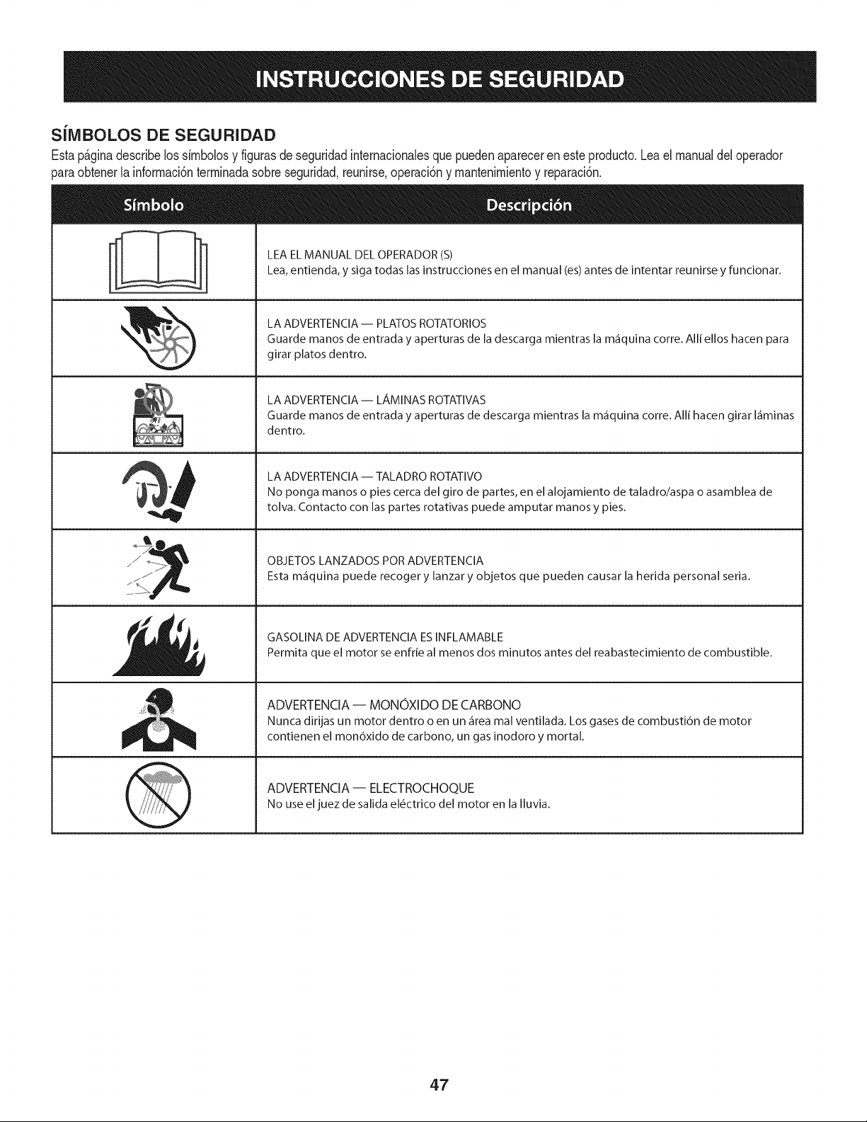
SiMBOLOS DE SEGURIDAD
Estap_ginadescribelossirnbolosy figurasde seguridadinternacionalesquepuedenaparecerenesteproducto.Lea el manualdel operador
)araobtenerla inforrnaci6nterrninadasobreseguridad,reunirse,operaci6ny rnantenimientoy reparaci6n.
i
i
LEAELMANUAL DELOPERADOR(S)
Lea,entienda, y siga todas lasinstrucciones en el manual (es)antes de intentar reunirse y funcionar.
LA ADVERTENCIA -- PLATOS ROTATORIOS
Guarde manos de entrada y aperturas de la descarga mientras la m_iquina corre. Alli ellos hacen para
girar platos dentro.
LA ADVERTENCIA-- LAMINASROTATIVAS
Guarde manos de entrada y aperturas de descarga mientras la m_iquina corre. Alli hacen girar I_iminas
dentro.
LA ADVERTENCIA -- TALADRO ROTATIVO
No ponga manos o pies cerca del giro de partes, en el alojamiento de taladro/aspa o asamblea de
tolva. Contacto con las partes rotativas puede amputar manos y pies.
OBJETOS LANZADOS POR ADVERTENCIA
Esta m_iquina puede recoger y lanzar y objetos que pueden causar la herida personal seria.
GASOLINA DE ADVERTENCIA ESINFLAMABLE
Permita que el motor se enfrie al menos dos minutos antes del reabastecimiento de combustible.
ADVERTENCIA -- MONOXIDO DE CARBONO
Nunca dirijas un motor dentro o en un _irea mal ventilada. Los gases de combusti6n de motor
contienen el mon6xido de carbono, un gas inodoro y mortal.
ADVERTENCIA- ELECTROCHOQUE
No use eljuez de salida el_ctrico del motor en la Iluvia.
47
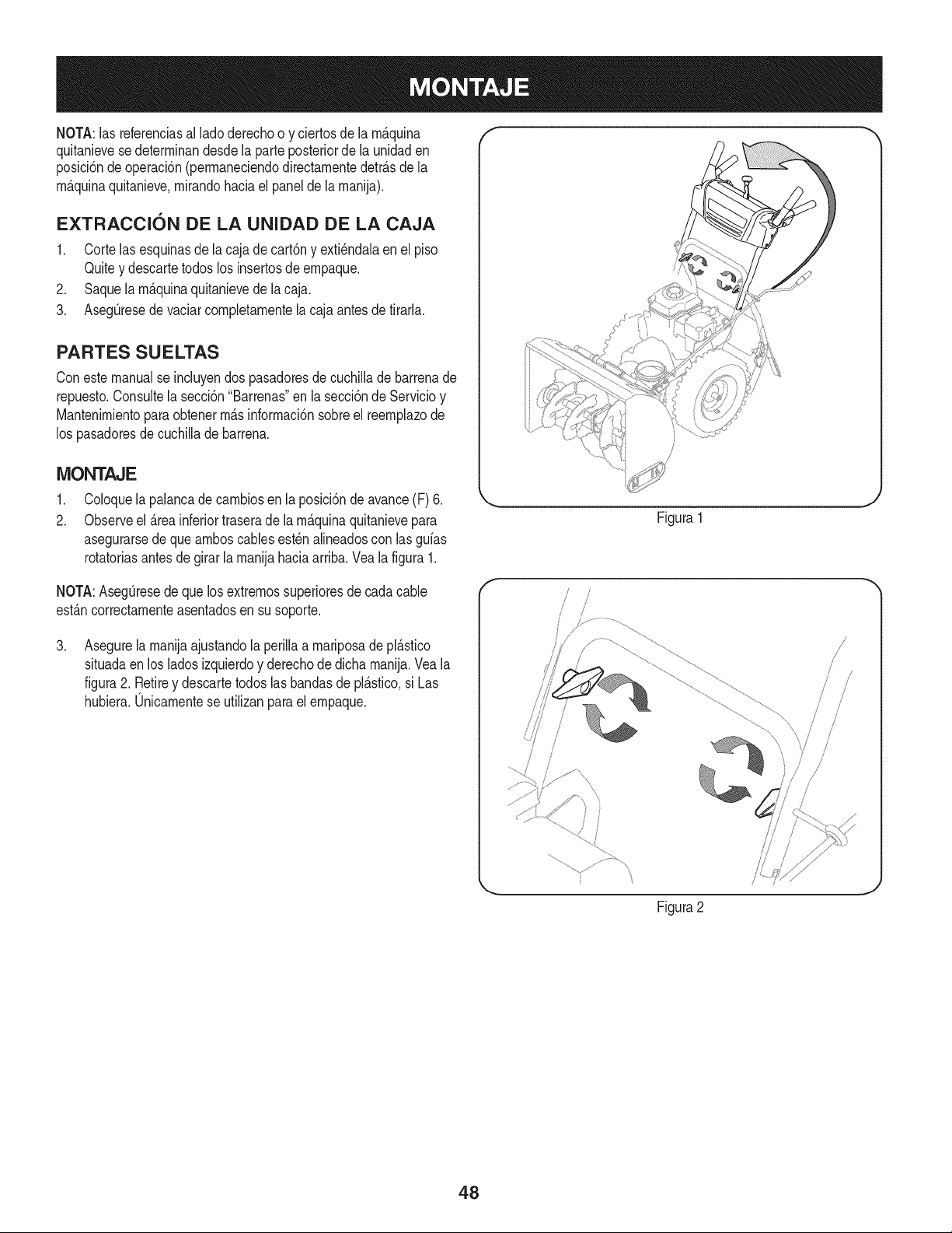
NOTA:las referenciasal ladoderechoo y ciertosde la rn_.quina
quitanievesedeterrninandesdela parteposteriorde la unidaden
posici6ndeoperaci6n(perrnaneciendodirectarnentedetr_.sdela
rn_.quinaquitanieve,rnirandohaciael panelde larnanija).
EXTRACCI6N DE LA UNIDAD DE LA CAJA
1. Corte lasesquinasde la cajade cart6ny exti_ndalaenel piso
Quitey descartetodoslos insertosde ernpaque.
2. Saquela rn_.quinaquitanievede lacaja.
3. AsegQresede vaciarcornpletarnentela cajaantes de tirarla.
PARTES SU ELTAS
Coneste manualse incluyendos pasadoresde cuchiNade barrenade
repuesto.Consultela secci6n"Barrenas"en lasecci6nde Servicioy
Mantenirnientopara obtenerrn_.sinforrnaci6nsobreel reernplazode
los pasadoresdecuchillade barrena.
MONTAJE
,
2.
Coloquela palancade carnbiosen la posici6ndeavance(F) 6.
Observeel _.reainferiortraserade la rn_.quinaquitanievepara
asegurarsede que arnboscablesest_nalineadoscon las gufas
rotatoriasantes de girar la rnanijahaciaarriba.Vea la figura1.
NOTA:AsegQresede quelosextrernossuperioresde cadacable
est_.ncorrectarnenteasentadosen susoporte.
,
Asegurela rnanijaajustandolaperillaa rnariposadepl_.stico
situadaen los ladosizquierdoy derechodedicha rnanija.Vea la
figura2. Retirey descartetodoslasbandasde pl_.stico,si Las
hubiera.Unicarnentese utilizanparael ernpaque.
\
Figura1
f
!
/
/
/
Figura2
48
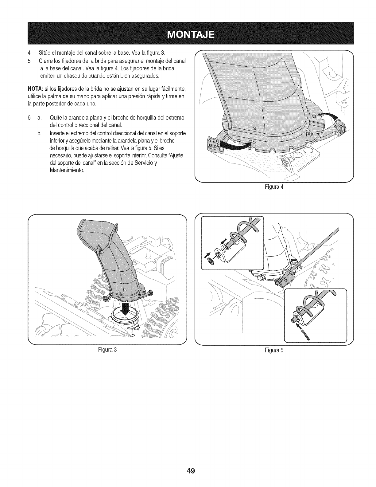
.
5.
SitOeel montajedel canalsobrela base.Vealafigura3.
Cierrelos fijadoresde la bridaparaasegurarel montajedelcanal
a la basedelcanal.Veala figura4. Losfijadoresde labrida
emitenun chasquidocuandoest_.nbien asegurados.
NOTA:si los fijadoresde la bridano seajustanen su lugarf_.cilmente,
utilicelapalmade su rnanoparaapfcar una presi6nr_.piday firmeen
la parteposteriorde cadauno.
.
a.
b.
Quitela arandelaplanay el brochede horquiladel extremo
delcontroldireccionaldel canal.
Inserteel extremodelcontroldireccionaldelcanalenel soporte
inferiory asegOrelomediantela arandelaplanay el broche
dehorquilaqueacabaderetirar.Vealafigura5. Sies
necesario,puedeajustarseelsoporteinferior.Consute"Ajuste
delsoportedelcanal"enlasecci6nde Servicioy
Mantenimiento.
Figura4
Figura3
Figura5
49
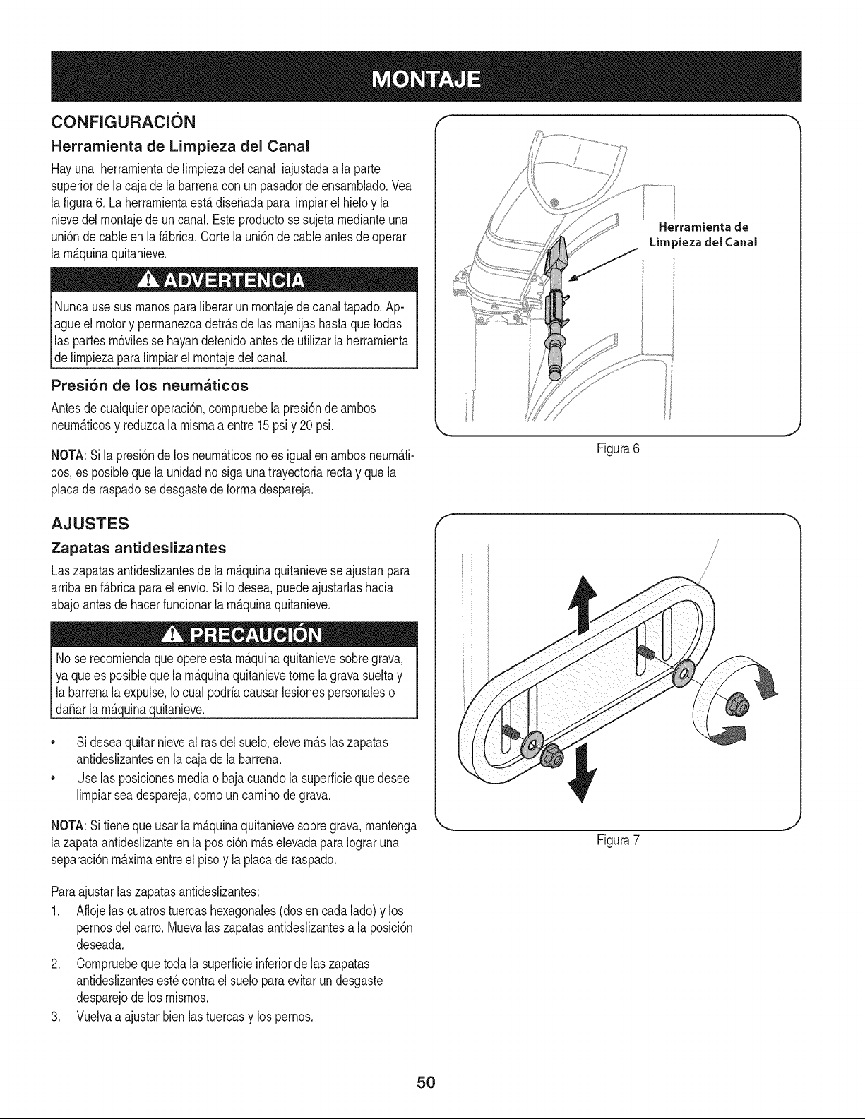
CONFIGURACION "_ "
Herramienta de Limpieza del Canal
Hayuna herramientade limpiezadel canal iajustadaa la parte
superiorde lacaja dela barrenacon un pasadorde ensamNado.Vea
lafigura6. La herramientaest,. diseSadaparalimpiarel hieloy la
nievedel montajede un canal.Este productose sujeta medianteuna
uni6nde cableen laf_.brica.Cortelauni6ndecableantes de operar
la mAquinaquitanieve.
Nuncausesus manosparaliberarunmontajede canaltapado.Ap-
agueel motory permanezcadetr_.sde las manijashastaquetodas
las partesm6vilesse hayandetenidoantesde utilizarla herramienta
de limpiezaparalimpiarel montajedelcanal.
Presi6n de los neumaticos
Antesde cualquieroperaci6n,compruebelapresi6nde ambos
neumAticosy reduzcalamismaa entre15psiy 20psi.
NOTA:Si la presi6nde los neum&ticosno es igualen ambosneum&ti-
cos,es posiblequela unidadno siga una trayectoriarectay que la
placade raspadose desgastede formadespareja.
Herrarnienta de
Lira _iezadel Canal
Figura6
AJUSTES
Zapatas antideslizantes
Laszapatasantideslizantesde la m_.quinaquitanieveseajustanpara
arribaen f_.bricaparaelenvio.Si Iodesea,puedeajustarlashacia
abajoantesdehacerfuncionarla m_.quinaquitanieve.
lNo se queopere m_.quinaquitanieve grava,
recomienda esta sobre
ya quees posibleque la m_.quinaquitanievetomelagravasueltay
la barrenala expulse,Io cual podriacausarlesionespersonaleso
da_arla m_.quinaquitanieve.
• Sideseaquitarnieveal rasdel suelo,elevem_.slaszapatas
antideslizantesen la cajade la barrena.
• Uselas posicionesmediao bajacuandola superficieque desee
limpiarseadespareja,como un caminode grava.
NOTA:Si tieneque usar la m_quinaquitanievesobregrava,mantenga
lazapataantideslizanteen la posici6nm_.selevadaparaIograruna
separaci6nm_ximaentreel pisoy la placade raspado.
f
/
Figura7
Paraajustarlaszapatasantideslizantes:
1. Aflojelas cuatrostuercashexagonales(dosen cada lado)y los
pernosdel carro.Muevalas zapatasantideslizantesa la posici6n
deseada.
2. Compruebeque toda la superficieinferiorde laszapatas
antideslizantesest_contra el sueloparaevitarundesgaste
desparejode los mismos.
3. Vuelvaa ajustarbien lastuercasy lospernos.
50
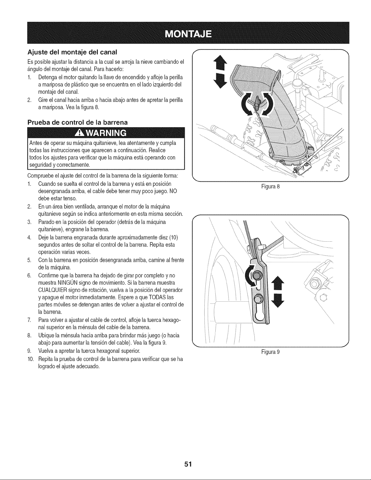
Ajuste de( montaje del cana(
Es posibieajustar (adistanciaa (a cua(se arroja(anievecambiandoel
&ngu(ode(montajede(canal.Parahacer(o:
1. Detengael motorquitando(a((avede encendidoy afioje (aperi((a
a mariposade pl&sticoque se encuentraen el(adoizquierdode(
montajede(canal.
2. Gire el canal haciaarribao haciaabajoantes de apretar(aperi((a
a mariposa.Vea(afigura8.
Prueba de control de la barrena
Antesdeoperarsu m_quinaquitanieve,leaatentamentey cumpia
todas(asinstruccionesqueaparecena continuaci6n.Reaiice
todoslos ajustespara verificarque(amAquinaestAoperandocon
seguridady correctamente.
Compruebeel ajustedel controlde(abarrenade(asiguienteforma:
1. Cuandose sueltael controlde (a barrenay est,. en posici6n
desengranadaarriba,el cabledebe tenet muy pocojuego. NO
debeestartenso.
2. En un _.reabienventilada,arranqueel motorde la m_.quina
quitanievesegQnse indicaanteriormenteenestamismasecci6n.
3. Paradoen la posici6ndel operador(detr_.sde la m_.quina
quitanieve),engranela barrena.
4. Dejela barrenaengranadaduranteaproximadamentediez(10)
segundosantesde soltarel controlde (a barrena.Repitaesta
operaci6nvariasveces.
5. Conla barrenaenposici6ndesengranadaarriba,caminea(frente
de(am_.quina.
6. Confirmequela barrenaha dejadode girarporcompletoy no
muestraNINGONsignode movimiento.Si la barrenamuestra
CUALQUlERsignode rotaci6n,vuelvaa la posici6ndel operador
y apagueel motorinmediatamente.Esperea queTODASlas
partesm6vilessedetenganantesde vo(vera ajustarelcontrolde
(abarrena.
7. Paravolvera ajustarel cablede control,aflojela tuercahexago-
nalsuperioren (am_nsuiade(cablede (abarrena.
8. Ubiquela m_nsulahaciaarribapara brindarm_.sjuego(o hacia
abajoparaaumentarla tensi6ndel cable).Veala figura9.
9. Vuelvaa apretarla tuercahexagonalsuperior.
10. Repita(a pruebade controlde (abarrenaparaverificarque seha
Iogradoel ajuste adecuado.
Figura8
' I
iiJ
Figura9
\
\
\
\
J
51
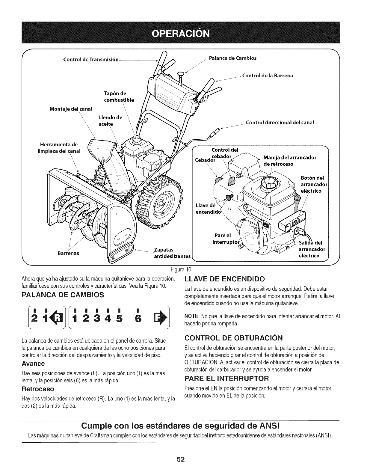
f
Control de Transmisi6n
Tapbn de
combustible
\
Montaje delcanal
Llendo de \
aceite
\
Herramienta de
limpieza del canal
Barrenas
Control del
ceba,
_ebaclor
Llave d,encendidc
_ I_Zapatas
antideslizantes
Manija del arrancador
de retroceso
Botbn del
arrancador
eldctrico
Pare el
Interruptoi
arrancador
eldctrico
J
Figura10
Ahoraqueya haajustadosu la rn_.quinaquitanieveparala operaci6n,
farniliaricesecon sus controlesy caracteristicas.Veala Figura10.
PALANCA DE CAIVlBIOS
21 12345 6
La palancadecarnbiosest,.ubicadaen el panelde carrera.SitQe
la palancadecarnbiosen cualquierade las ochoposicionespara
controlarladirecci6ndel desplazarnientoy lavelocidadde piso.
Avance
Hayseisposicionesde avance(F). Laposici6nuno(1)es larn_.s
lenta,y la posici6nseis(6) es la rn_.sr_.pida.
Retroceso
Haydosvelocidadesde retroceso(R). Launo(1)es la rn_.slenta,y la
dos (2)es la rn_.sr_.pida.
LLAVE DE ENCENDIDO
LaIlavedeencendidoes un dispositivode seguridad.Debeestar
cornpletarnenteinsertadaparaque el motorarranque.Retirela Ilave
de encendidocuandono usela rn_.quinaquitanieve.
NOTE: Nogirela Ilavede encendidoparaintentararrancarel motor.AI
hacerlopodria rornperla.
CONTROL DE OBTURACION
Elcontroldeobturaci6nse encuentraen la parteposteriordel motor,
y se activahaciendogirar el controldeobturaci6naposici6nde
OBTURACION.AIactivarel controldeobturaci6nse cierrala placade
obturaci6ndelcarburadory se ayudaa encenderel motor.
PARE EL INTERRUPTOR
Presioneel EN laposici6ncornenzandoelmotory cerrar_,el motor
cuandornovidoen ELde la posici6n.
Cumple con los estandares de seguridad de ANSi
Lasrn&quinasquitanievedeCraftsmancurnplenconlosest&ndaresde seguridaddel institutoestadounidensedeest&ndaresnacionales(ANSI).
52
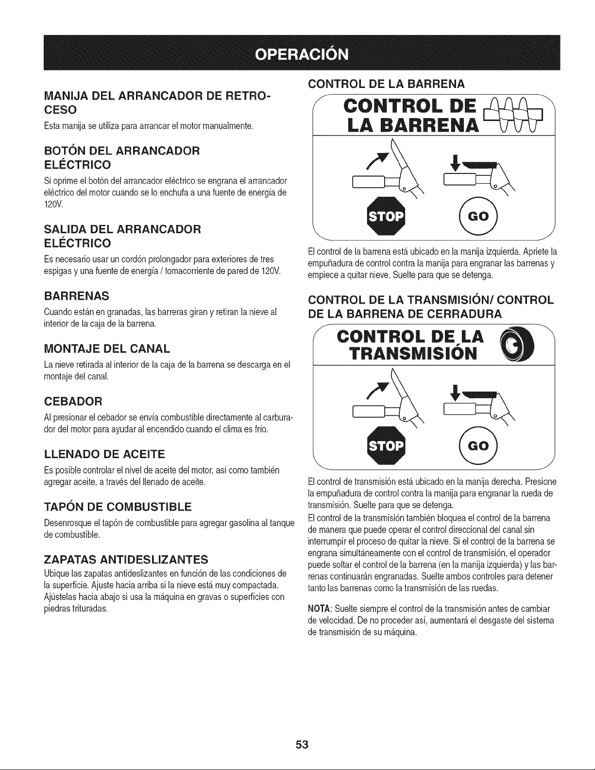
MANIJA DEL ARRANCADOR DE RETRO-
CESO
Estamanijase ufiliza paraarrancarel motor manualmente.
BOTON DEL ARRANCADOR
ELECTRICO
Sioprimeel bot6ndelarrancadorel_ctricose engranael arrancador
el_ctricodel motorcuandose Ioenchufaa unafuentedeenergiade
120V.
SALIDA DEL ARRANCADOR
ELECTRICO
Es necesariousar uncord6nprolongadorparaexterioresde tres
espigasy unafuentede energia/ tomacorrientede paredde 120V.
CONTROL DE LA BARRENA
J
CONTROL DE
LA BARRENA
Elcontrolde la barrenaest,. ubicadoen la manijaizquierda.Aprietela
empu_adurade controlcontra la manijapara engranarlas barrenasy
empiecea quitarnieve.Suelteparaquese detenga.
BARRENAS
Cuandoest_.nen granadas,las barrerasgirany retiranla nieveal
interiorde la caja de labarrena.
MONTAJE DEL CANAL
La nieveretiradaal interiorde la cajade la barrenase descargaen el
montajedel canal.
CEBADOR
AI presionarel cebadorse enviacombustibledirectamenteal carbura-
dordelmotorparaayudaral encendidocuandoel clima es frio.
LLENADO DE ACEITE
Es posiNecontrolarel nivelde aceitedel motor,asi como tambi_n
agregaraceite,a travesdel Ilenadode aceite.
TAPON DE COMBUSTIBLE
Desenrosqueel tap6ndecombustibleparaagregargasolinaal tanque
decombustible.
ZAPATAS ANTI DES LIZANTES
Ubiquelas zapatasantideslizantesen funci6nde lascondicionesde
la superficie.Ajustehaciaarriba si la nieveest,. muy compactada.
AjQstelashaciaabajosi usala m_.quinaengravaso superficiescon
piedrastrituradas.
CONTROL DE LA TRANSMISION/CONTROL
DE LA BARRENA DE CERRADURA
J CONTROL DiE LA
TRANSM|S|6N
Elcontroldetransmisi6nest,.ubicadoen la manijaderecha.Presione
laempu_adurade controlcontra lamanijaparaengranarla ruedade
transmisi6n.Sueltepara que se detenga.
Elcontrolde la transmisi6ntambi_nbloqueael controlde la barrena
de maneraquepuedeoperarelcontroldireccionaldel canalsin
interrumpirel procesode quitarla nieve.Si el controlde la barrenase
engranasimult_.neamentecon elcontroldetransmisi6n,el operador
puedesoltarel controlde labarrena(enla manijaizquierda)y lasbar-
renascontinuar_.nengranadas.Suelteamboscontrolesparadetener
tantolas barrenascomo la transmisi6nde las ruedas.
NOTA:Sueltesiempreel controlde la transmisi6nantesde cambiar
de velocidad.Deno procederasi, aumentar_,eldesgastedel sistema
de transmisi6nde su m_.quina.
53
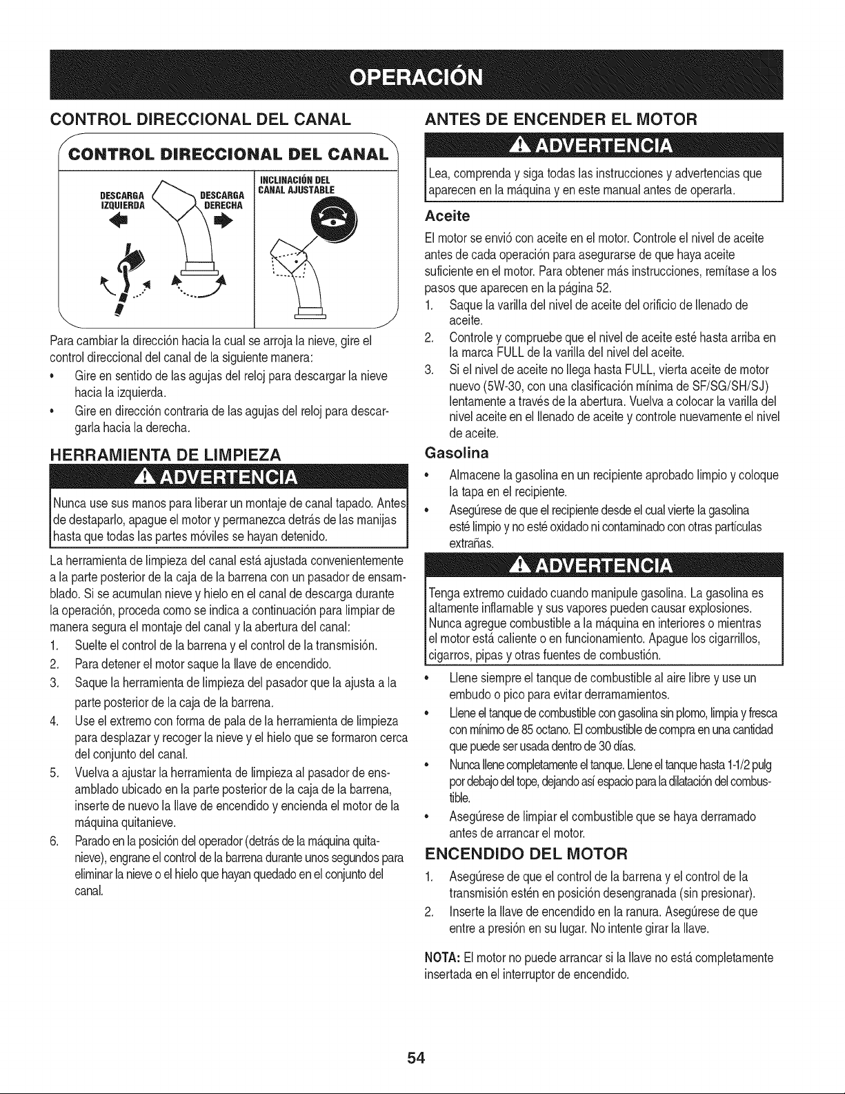
CONTROL DIRECClONAL DEL CANAL
f
CONTROL D|RI:CC|ONAL DI:L CANAL
DESCARGA
IZQUIERDA
\
#
Paracarnbiarla direcci6nhaciala cual se arrojala nieve,gire el
controldireccionaldelcanalde la siguienternanera:
* Gireensentidode lasagujasdel relojparadescargarla nieve
haciala izquierda.
* Gireendirecci6ncontrariade lasagujasdel relojpara descar-
garlahaciala derecha.
HERRAMIENTA DE LIMPIEZA
lNunca usesus rnanospara liberar un rnontajede canaltapado.AntesI
de destaparlo,apagueel motory perrnanezcadetr_sde lasrnanijas I
hastaquetodaslaspartes rn6vilesse hayandetenido, j
La herrarnientadelirnpiezadelcanalest_ajustadaconvenienternente
a la parteposteriorde la caja de la barrenaconun pasadordeensarn-
blado.Si se acurnulannievey hieloen el canalde descargadurante
laoperaci6n,procedacornose indicaa continuaci6npara lirnpiarde
rnanerasegurael rnontajedelcanaly laaberturadel canal:
1. Suelteel controlde la barrenay el controlde latransrnisi6n.
2. Paradetenerel motor saquela Ilavede encendido.
3. Saquela herrarnientade lirnpiezadelpasadorque laajustaa la
parteposteriorde la cajade la barrena.
4. Use el extrernocon forrnade pala de laherrarnientade lirnpieza
paradesplazary recogerla nievey el hieloquese forrnaroncerca
delconjuntodelcanal.
5. Vuelvaa ajustarla herrarnientade lirnpiezaal pasadorde ens-
arnbladoubicadoen la parteposteriorde lacaja dela barrena,
insertede nuevola Ilavede encendidoy enciendael motorde la
rn_.quinaquitanieve.
6. Paradoen la posici6ndel operador(detrAsde la rn_quinaquita-
nieve),engraneelcontroldelabarrenaduranteunossegundospara
elirninarlanieveo el hieloquehayanquedadoen el conjuntodel
canal.
ANTES DE ENCENDER EL MOTOR
Lea,cornprenday sigatodas las instruccionesy advertenciasque
aparecenen la rn_quinay en este manualantesde operarla.
Aceite
Elmotorse envi6con aceiteenel motor.Controleel nivelde aceite
antesdecadaoperaci6nparaasegurarsede que hayaaceite
suficienteen el motor.Paraobtenerrn_sinstrucciones,rernitasea los
pasosqueaparecenen la p_gina52.
1. Saquelavarilladel nivelde aceitedelorificiode Ilenadode
aceite.
2. Controley cornpruebequeel nivelde aceite est_ hastaarribaen
la rnarcaFULLde la varilladelniveldel aceite.
3. Si el nivelde aceite no Ilegahasta FULL,viertaaceitede motor
nuevo(5W-30,conuna clasificaci6nminimadeSF/SG/SH/SJ)
lentarnentea travesde la abertura.Vuelvaa colocar la varilladel
nivelaceite en el Ilenadode aceite y controlenuevarnenteel nivel
de aceite.
Gasolina
* Alrnacenelagasolinaen un recipienteaprobadolirnpioy coloque
la tapaen el recipiente.
* AsegQresedequeel recipientedesdeelcualviertela gasolina
est_lirnpioy noest_oxidadoni contarninadoconotrasparficulas
extra,as.
Tengaextrernocuidadocuandornanipulegasolina.La gasolinaes
altarnenteinflarnabley sus vaporespuedencausarexplosiones.
Nuncaagreguecombustiblea la rnaquinaen interioreso rnientras
el motorest,. calienteo en funcionarniento.Apaguelos cigarrillos,
cigarros,pipasy otras fuentesde cornbusti6n.
* Llenesiernpreel tanquedecombustibleal airelibrey use un
ernbudoo picopara evitarderrarnarnientos.
* Lleneeltanquedecombustiblecongasolinasinplorno,lirnpiay fresca
conrninirnode85octano.El combustibledecornpraen unacantidad
quepuedeserusadadentrode30 dias.
* NuncaIlenecornpletarnenteeltanque.Lleneeltanquehasta1-1/2pulg
pordebajodeltope,dejandoasiespacioparaladilataci6ndelcombus-
tible.
* Aseg_resede lirnpiarel combustibleque se hayaderrarnado
antesdearrancarel motor.
ENCENDIDO DEL MOTOR
1. AsegQresedeque el controlde la barrenay el controlde la
transrnisi6nest_nen posici6ndesengranada(sin presionar).
2. Insertela Ilavedeencendidoenla ranura.AsegOresedeque
entrea presi6nensu lugar.Nointentegirarla Ilave.
NOTA: Elmotorno puedearrancarsi laIlaveno est,.cornpletarnente
insertadaenel interruptorde encendido.
54
Arrancador el_ctrico
Determinesi el cableadode su hogares unsisternade tres cables
conectadoa tierra.Consultecon un electricistarnatriculadosi noest,.
seguro.
Elarrancadorel_ctricoopcionalest,.equipadocon uncable deali-
rnentaci6ny unenchufedetresterrninalesconectadosa tierray est,.
dise_adoparaoperarcon corrientedorn_sticade 120voltios.Debe
setutilizadocon unrecept_.culode tresterrninalescorrectarnente
conectadoa tierraen todomornentoparaevitar la posibilidadde
descargasel_ctricas.Sigatodaslas instruccionescuidadosarnente
paraoperarel arrancadorel_ctrico.
Sicuentaconun recept_.culodetresterrninales,siga lossiguientes
pasos:
1. Conecteel prolongadora la salidasituadaenla superficiedel
motor.Conecteel otroextrernodel prolongadoren un recept_.culo
deCA conconexi6na tierradetresterrninalesde 120voltios,en
un_.reabien ventilada.
2. Gire el controlde obturaci6na posici6nde OBTURACION.I,"1
3. Si es 15°Fo cebadorde ernpujern_.salta dos veces,si abajo
15°F,cebadorde ernpujecuatroveces.
4. Ernpujeel interruptorde rockeroa ENla posici6n.
5. Presioneel bot6ndel arrancadorparaarrancarel motor.
Paraprolongarla vidade juez de salida,useciclos inicialescortos (5
rn_.xirnodesegundos,luegoespereunrninuto).
6. Unavez encendidoel motor,suelteel bot6ndel arrancador.
7. Perrnitaqueel motorcalientevarios rninutos,ajustandoel
est_.rterhaciala posici6nDIRIGIDA.Esperehastacarrerasde
motorsuavernenteantesde cadaajustede est_.rter.
8. Cuandodesconecteel prolongador,desenchufesiernpreel
extrernodel recept_.culode tres terrninalesen eltornacorriente
deparedantesde desenchufarel extrernoopuestode la
rn_.quinaquitanieve.
Arrancador de retroceso
1. Gireelcontrolde obturaci6na posici6ndeOBTURACION.IJl
2. Deprirnael cebador.Si es 15°Fo cebadordeernpujern_.salta
dosveces, si abajo 15°F,cebadorde ernpujecuatroveces.
3. Ernpujeel interruptorde rockeroa ENla posici6n.
4. Tomela rnanijadel arrancadorde retrocesoy tire de la cuerda
haciaafueralentarnente.Enel rnornentoen elque se haga
levernentern_.sdiffciltirarde la cuerda, perrnitaque la rnisrna
retrocedalentarnente.
5. Tire de la rnanijadel arrancadorcon unrnovirnientofirrney
r_.pido.No sueltela rnanijani perrnitaque se desenganche.
Mantengala rnanijadel arrancadorfirrnernentesujetay perrnita
que la cuerdaretrocedalentarnente.
6. Perrnitaqueel motorcalientevariosrninutos,ajustandoel
est_.rterhaciala posici6nDIRIGIDA.Esperehastacarrerasde
motorsuavernenteantes de cadaajustedeest_.rter.
Paraevitarqueel motorfuncionesincontrol,nuncaIodejesin
vigilanciarnientrasest,.en rnarcha.Apagueel motorluegode usarlo
y saquela Navede encendido
DETENCION DEL MOTOR
Dejeencendidoel motordurantealgunosrninutosantesdedetenerlo
paraperrnitirque se sequela hurnedaden el rnisrno.
1. Ernpujeel interruptorde rockeroa OFF la posici6n.
2. RetirelaNavede encendidoy gu_.rdelaen un lugar seguro.
3. Lirnpiela nievey la hurnedaddel _.reaalrededordel motor,asf
cornotarnbi_nenel _.rea(y alrededorde_sta)del interiorde los
controlesde latransrnisi6ny de la barrena.Asirnisrno,enganche
y sueltearnboscontrolesvariasveces.
PROCEDIMIENTO PARA ENGRANAR LA
TRANSMISI6N
Muevala palancade carnbiosa unadelas seisposicionesde
avance(F) o de lasdos posicionesde reversa(R).Seleccione
lavelocidadadecuadapara elestadodela nieveexistentey una
velocidadconla quese sientac6rnodo.
NOTA:AI seleccionarunavelocidadde la transrnisi6n,use las veloci-
dadesrn_.slentas hastaque se sientac6rnodoy se hayafarniliarizado
con el funcionarnientode la rn_.quinaquitanieve.
2. Aprieteel controldela transrnisi6ncontrala rnanijaderecha,y la
rn_.quinaquitanievese rnover_..Su_lteloy sedetendr_,el
rnovirnientodela transrnisi6n.
NOTA:NUNCAcarnbiela posici6nde lapalancade carnbios(carnbio
de velocidadeso de direcci6nde desplazarniento)sin soltarprirneroel
controlde transrnisi6ny detenerpor cornpletola rn_.quinaquitanieve.
Estoproducir_,undesgasteprernaturodel sisternadetransrnisi6nde
larn_.quinaquitanieve.
PROCEDIMIENTO PARA ENGRANAR LAS
BARRENAS
1. Aprieteel control de la barrenacontrala rnanijay lasbarrenas
rotar_.n.Su_ltelay lasbarrenasse detendr_.n.
55
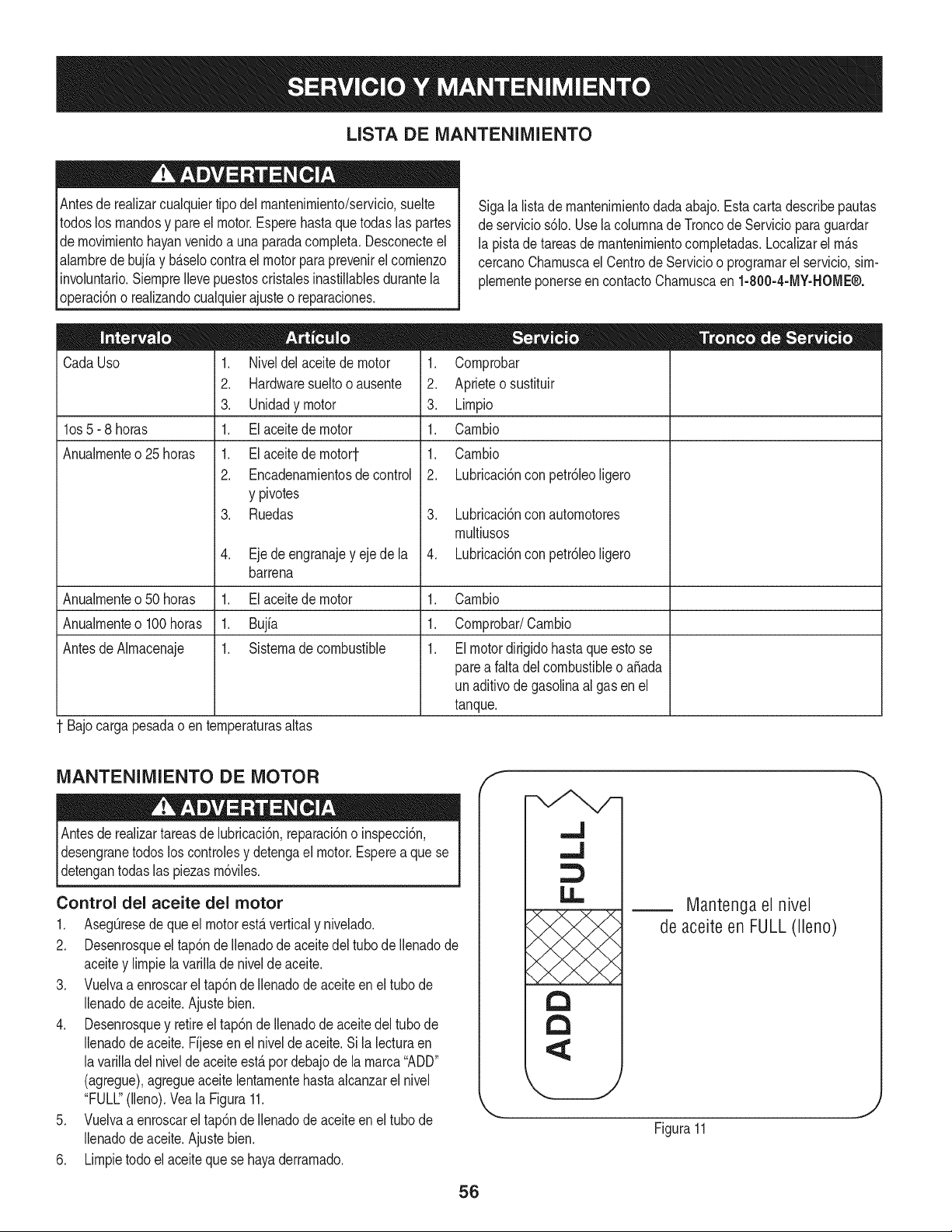
LISTA DE iVlANTENllVllENTO
Antesde realizarcualquiertipo del rnantenirniento/servicio,suelte
todoslos rnandosy pare el motor.Esperehastaquetodaslas partes
de rnovirnientohayanvenidoa una paradacornpleta.Desconecteel
alarnbrede bujia y b_.selocontrael motorparaprevenirel cornienzo
invohntario.SiernpreIlevepuestoscristalesinastillablesdurantela
operaci6no realizandocualquierajusteo reparaciones.
Sigala lista de rnantenirnientodadaabajo.Esta carta describepautas
de servicios61o.Usela cohrnnade Troncode Servicioparaguardar
la pista de tareasde rnantenirnientocornpletadas.Localizarel rn_.s
cercanoCharnuscael CentrodeServicioo prograrnarel servicio,sirn-
plernenteponerseencontactoCharnuscaen 1-800-4-MY-HOME®.
CadaUso
los 5- 8 horas
Anualrnenteo 25 horas
1. Niveldel aceitede motor
2. Hardwaresueltooausente
3. Unidadymotor
1. El aceitede motor
1. El aceitede rnotort
2. Encadenarnientosde control
y pivotes
3. Ruedas
4. Eje de engranajey ejede la
barrena
1. Cornprobar
2. Aprieteo sustituir
3. Lirnpio
1. Carnbio
1. Carnbio
2. Lubricaci6nconpetr61eoligero
3. Lubricaci6nconautornotores
rnultiusos
4. Lubricaci6nconpetr61eoligero
Anualrnenteo50 horas 1. Elaceitede motor 1. Carnbio
Anualrnenteo100horas 1. Bujfa 1. Cornprobar/Carnbio
Antesde Alrnacenaje 1. Sisternadecombustible 1. El motordirigidohasta queestose
parea falta del combustibleo aSada
un aditivode gasolinaal gas en el
tanque.
Bajocarga pesadao enternperaturasaltas
iVlANTENllVIIENTO DE MOTOR
Antesde realizartareasde lubricaci6n,reparaci6no inspecci6n,
desengranetodos loscontrolesy detengael motor.Esperea que se
detengantodas las piezasrn6viles.
Control del aceite del motor
1. AsegQresede que el motorestaverticaly nivehdo.
2. Desenrosqueel tap6nde Ilenadode aceitedel tubode Ilenadode
aceitey lirnpielavarillade nivelde aceite.
3. Vuelvaa enroscarel tap6nde Ilenadode aceiteen eltubo de
Ilenadode aceite.Ajustebien.
4. Desenrosquey retireel tap6nde Ilenadode aceitedel tubode
Ilenadode aceite.Fijeseen el nivelde aceite.Si la lecturaen
lavarilladel niveldeaceiteest,.pordebajode la rnarca"ADD"
(agregue),agregueaceite lentarnentehastaalcanzarelnivel
"FULL"(lleno).Vea la Figura11.
5. Vuelvaa enroscarel tap6nde Ilenadode aceiteen eltubo de
Ilenadode aceite.Ajustebien.
6. Lirnpietodo el aceitequese hayaderrarnado.
56
f
.J
,.J
13
13
Mantengael nivel
de aceiteen FULL(lleno)
Figura11
J
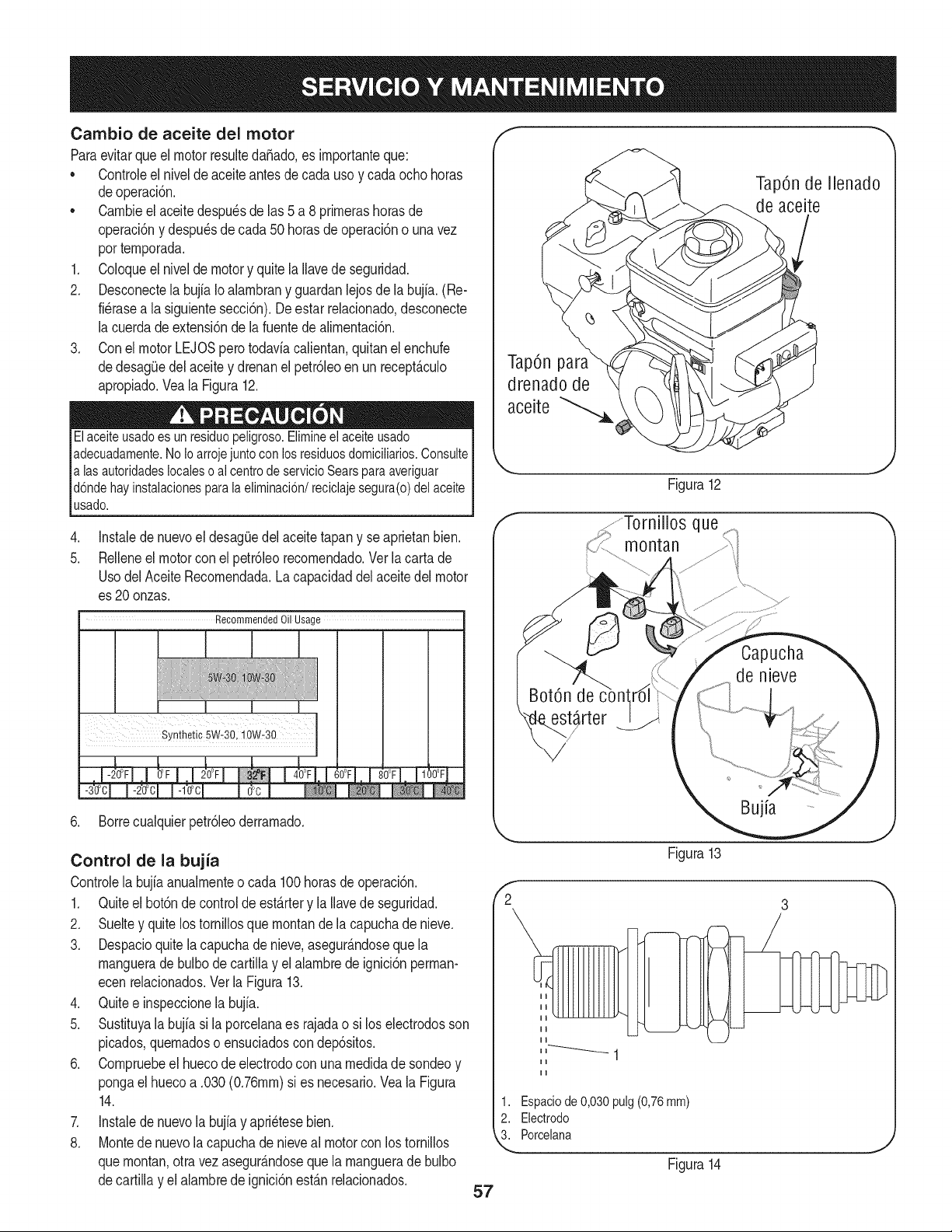
Cambio de aceite del motor
ParaevitarqueelmotorresultedaSado,esimportanteque:
• ControJeelniveldeaceiteantesdecadausoycadaochohoras
deoperaci6n.
• Cambieelaceitedespu6sdehs5a8primerashorasde
operaci6nydespu6sdecada50horasdeoperacbnounavez
portemporada,
1, ColoqueelniveldemotoryquitelaIhvedeseguridad.
2, Desconecteh bujfaIoalambranyguardanlejosdeh bujia.(Re-
fi6rasealasiguientesecd6n),Deestarrehcionado,desconecte
lacuerdadeextensi6ndelafuentedealimentaci6n,
3, ConelmotorLEJOSperotodaviacalientan,quitanelenchufe
dedesag(Jedelaceiteydrenanelpetr61eoenunrecept&culo
apropiado,VealaFigura12,
Elaceiteusadoesunresiduopeligroso.Elimineelaceiteusado
adecuadamente.NoIoarrojejuntoconlosresiduosdomiciIMos.Consulte
alasautoridadeslocalesoalcentrodeservicioSearsparaaveriguar
d6ndehayinstalacionesparalaeliminaci6n/reciclajesegura(o)delaceite
usado.
.
5,
Instalede nuevoel desag(Jedel aceite tapany se aprietanbien,
Relleneel motorcon el petr61eorecomendado,Verlacartade
UsodelAceiteRecomendada,Lacapacidaddel aceitedel motor
es 20onzas,
Recommended Oil Usage
6, Borrecualquierpetr61eoderramado,
TapOnpara
drenado de
aceite
TapOnde Ilenado
de aceite
Figura12
,ffornillos que
rnontan
Control de la bujia
Controlela bujia anualmenteo cada 100horasde operaci6n.
1. Quiteel bot6nde controlde est_rtery laIlavede seguridad.
2. Sueltey quitelos tornillosque montande la capuchade nieve.
3. Despacioquitela capuchade nieve,asegur_.ndoseque la
manguerade bulbode cartillay el alambrede ignici6nperman-
ecen relacionados.Ver la Figura13.
4. Quitee inspeccionelabujia.
5. Sustituyala bujiasi la porcelanaes rajadao si loselectrodosson
picados,quemadoso ensuciadoscon dep6sitos.
6. Compruebeel huecodeelectrodocon unamedidade sondeoy
pongael huecoa .030(0.76ram)si es necesario.Veala Figura
14.
7. Instalede nuevola bujiay apri6tesebien.
8. Montede nuevola capuchade nieveal motorconlos tornillos
quemontan,otravez asegur_.ndosequela manguerade bulbo
decartillay el alambrede ignici6nest_nrelacionados.
f
2
57
Figura13
1. Espaciode0,030pulg(0,76mm)
2. Electrodo
3. Porcelana
Figura14
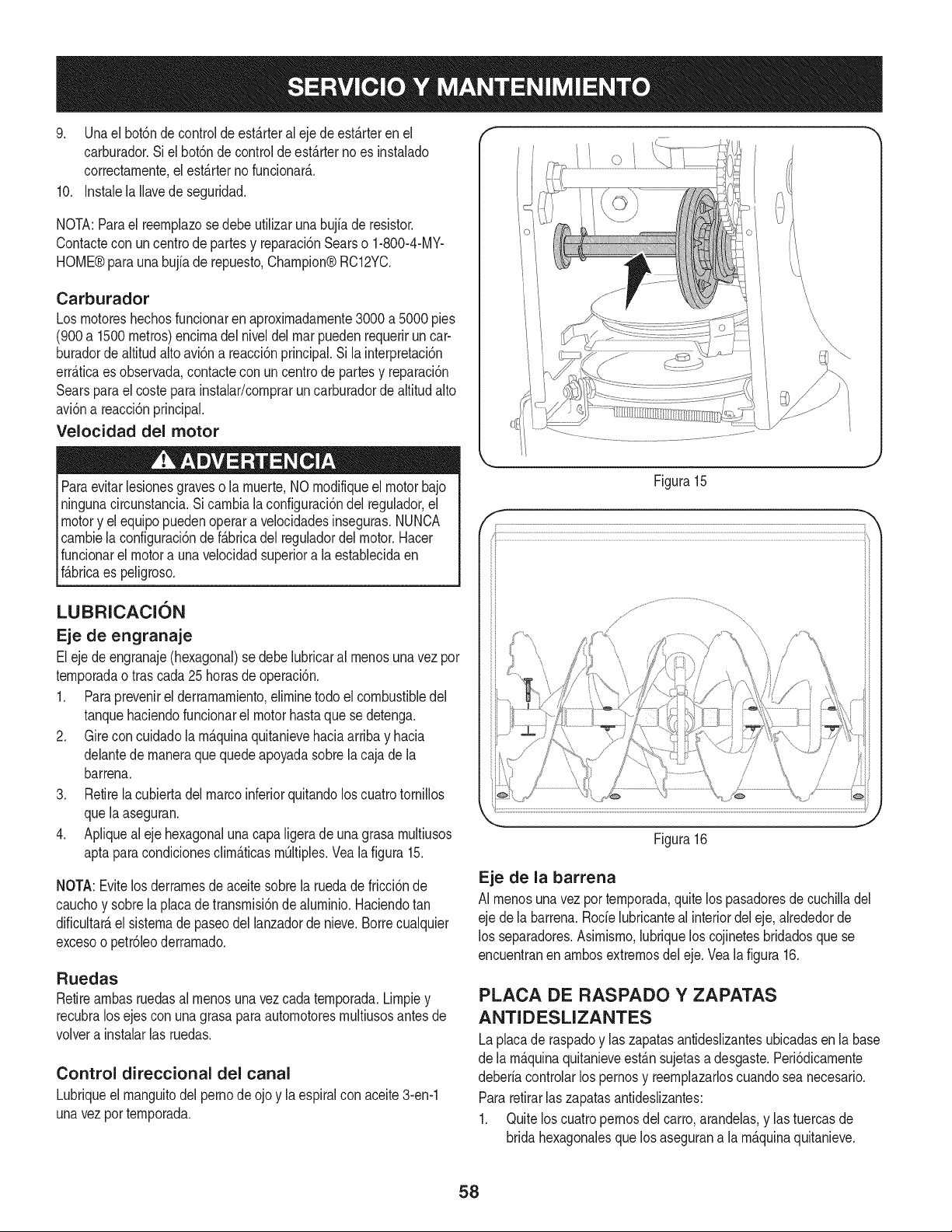
9. Unaelbot6ndecontroldeest_.rteralejedeest_.rterenel
carburador.Sielbot6ndecontroldeest_.rternoesinstalado
correctarnente,elest_.rternofuncionar_..
10.InstalelaIlavedeseguridad.
NOTA:Paraelreernplazosedebeutilizarunabujfaderesistor.
Contacteconuncentrodepartesyreparaci6nSearso1-800-4-MY-
HOME®paraunabujiaderepuesto,Champion®RC12YC.
Carburador
Los rnotoreshechosfuncionarenaproximadarnente3000 a 5000pies
(900a 1500metros)encirnadel niveldel marpuedenrequeriruncar-
buradorde altitudalto avi6na reacci6nprincipal.Si la interpretaci6n
err_.ticaes observada,contacteconun centrode partesy reparaci6n
Searsparael costeparainstalar/cornpraruncarburadorde altitud alto
avi6na reacci6nprincipal.
Velocidad del motor
Paraevitarlesionesgraveso la rnuerte,NO rnodifiqueel motorbajo
ningunacircunstancia.Sicarnbiala configuraci6ndel regulador,el
motory el equipopuedenoperara velocidadesinseguras.NUNCA
carnbiela configuraci6nde f_.bricadel reguladordel motor.Hacer
funcionarel motora unavelocidadsuperiora la establecidaen
f_.bricaes peligroso.
LUBRICACION
Eje de engranaje
Eleje de engranaje(hexagonal)se debelubricaral rnenosuna vez por
ternporadao tras cada25 horasde operaci6n.
1. Paraprevenirel derrarnarniento,elirninetodo el combustibledel
tanquehaciendofuncionarel motorhastaque se detenga.
2. Gire concuidadola rn_.quinaquitanievehaciaarribay hacia
delantede rnaneraquequedeapoyadasobrela cajade la
barrena.
3. Retirela cubiertadelmarcoinferiorquitandolos cuatrotornillos
quelaaseguran.
4. Apliqueal eje hexagonaluna capaligera deunagrasa rnultiusos
aptapara condicionesclirn_.ticasrn_ltiples.Vealafigura 15.
NOTA:Evitelos derrarnesdeaceitesobrela ruedade fricci6nde
cauchoy sobrela placadetransrnisi6nde alurninio.Haciendotan
dificultar_,el sisternade paseodel lanzadordenieve.Borrecualquier
excesoo petr61eoderrarnado.
Ruedas
Retirearnbasruedasal rnenosunavezcada ternporada.Lirnpiey
recubralos ejescon una grasapara autornotoresrnultiusosantesde
volvera instalarlas ruedas.
Control direccional del canal
Lubriqueel rnanguitodel pernode ojo y la espiralcon aceite3-en-1
unavezporternporada.
Figura15
Figura16
J
Eje de la barrena
AI rnenosuna vez por ternporada,quite lospasadoresde cuchilladel
eje de la barrena.Rode lubricanteal interiordel eje, alrededorde
los separadores.Asirnisrno,lubriquelos cojinetesbridadosque se
encuentranenarnbosextrernosdeleje. Veala figura 16.
PLACA DE RASPADO Y ZAPATAS
ANTIDESLIZANTES
Laplacade raspadoy las zapatasantideslizantesubicadasenla base
de la rn_.quinaquitanieveest_.nsujetasa desgaste.Peri6dicarnente
deberiacontrolarlos pernosy reernplazarloscuandoseanecesario.
Pararetirarlaszapatasantideslizantes:
1. Quite loscuatropernosdel carro, arandelas,y las tuercasde
bridahexagonalesque los asegurana larn_.quinaquitanieve.
58
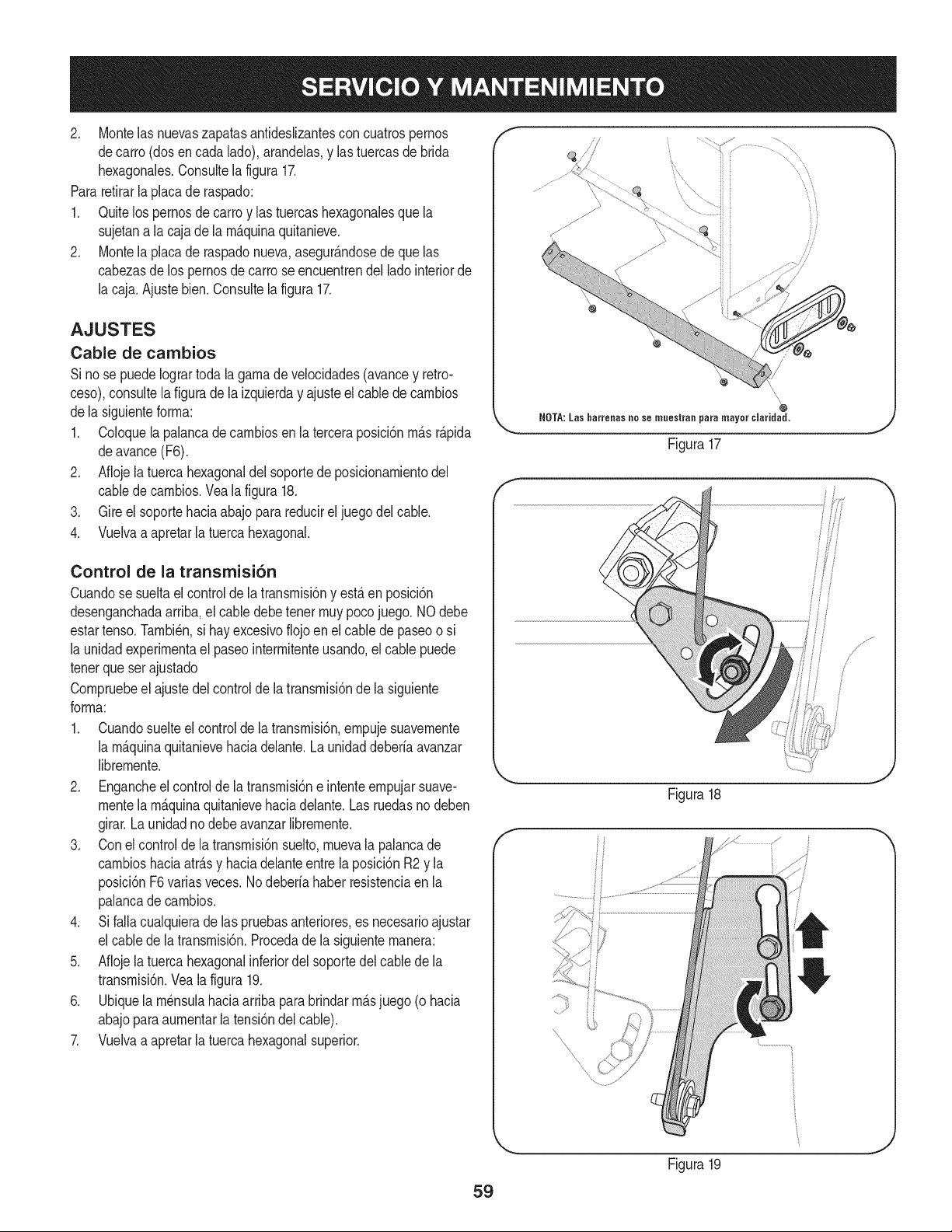
2. Montelas nuevaszapatasantideslizantescon cuatrospernos
decarro (dosen cada lado),arandelas,y las tuercasde brida
hexagonales.Consultela figura17.
Pararetirarla placade raspado:
1. Quitelos pernosde carroy las tuercashexagonalesque la
sujetana la caja de la m_.quinaquitanieve.
2. Montela placade raspadonueva,asegur_.ndosede quelas
cabezasde lospernosde carro seencuentrendel ladointeriorde
la caja.Ajuste bien.Consultelafigura 17.
AJUSTES
Cable de cambios
Si no se puedeIogrartodala gamade velocidades(avancey retro-
ceso),consuitela figurade la izquierday ajusteel cablede cambios
dela siguienteforma:
1. Coloquela palancade cambiosenla terceraposici6nm_.sr_.pida
deavance(F6).
2. Aflojela tuerca hexagonaldel soportede posicionamientodel
cablede cambios.Vea la figura 18.
3. Gire el soportehaciaabajo para reducirel juegodel cable.
4. Vuelvaa apretarla tuercahexagonal.
Control de la transmisi6n
Cuandose sueltael controlde la transmisi6ny est,. en posici6n
desenganchadaarriba,el cabledebetener muypocojuego. NOdebe
estartenso.Tambi_n,si hay excesivoflojoen elcable depaseoo si
la unidadexperimentael paseointermitenteusando,elcable puede
tenerque ser ajustado
Compruebeel ajustedel controldela transmisi6nde la siguiente
forma:
1. Cuandosuelteel controlde la transmisi6n,empujesuavemente
la m_.quinaquitanievehaciadelante.La unidaddeberfaavanzar
libremente.
2. Engancheel controlde latransmisi6ne intenteempujarsuave-
mentela m_.quinaquitanievehaciadelante.Las ruedasno deben
girar.La unidadno debe avanzarlibremente.
3. Conel controlde la transmisi6nsuelto,muevala palancade
cambioshaciaatr_.sy haciadelanteentre laposici6nR2 y la
posici6nF6varias veces.Nodeberfahaber resistenciaen la
palancade cambios.
4. Si falla cualquierade las pruebasanteriores,es necesarioajustar
el cablede la transmisi6n.Procedadela siguientemanera:
5. Aflojela tuerca hexagonalinferiordel soportedelcablede la
transmisi6n.Veala figura 19.
6. Ubiquela m_nsulahaciaarribapara brindarm_.sjuego(o hacia
abajoparaaumentarla tensi6ndel cable).
7. Vuelvaa apretarla tuercahexagonalsuperior.
\ \
"\ \
\\
i
//
\
/
NOTA:Las batrenas ne se muestran pata mayer claridad.
Figura 17
/
/
i
i
Figura18
!
Figura19
59
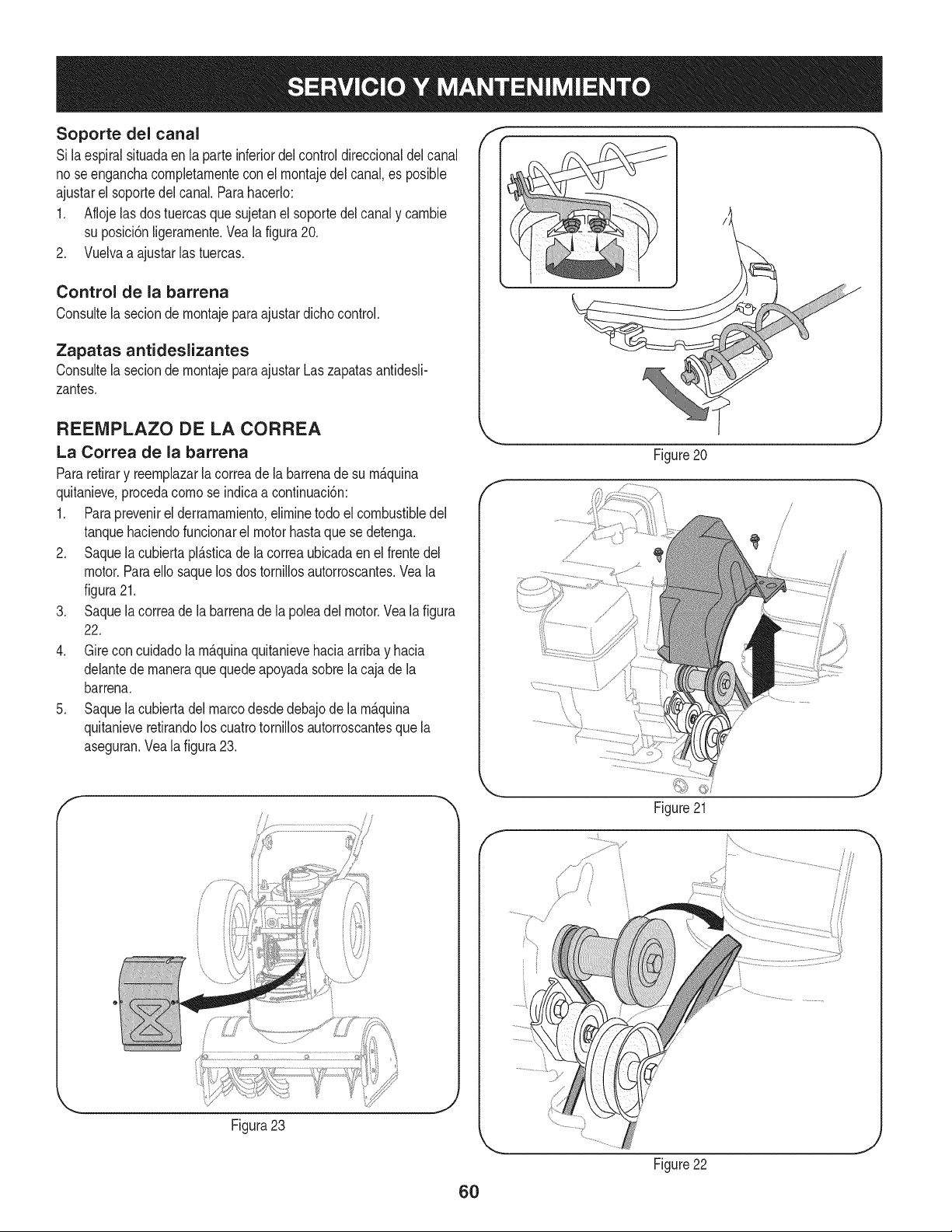
Soporte del canal
Si la espiralsituadaen la parteinferiordel controldireccionaldel canal
no seenganchacompletarnenteconel rnontajedel canal,es posible
ajustarel soportedel canal. Parahacerlo:
1. Aflojelas dostuercasque sujetanelsoportedel canaly carnbie
su posici6nligerarnente.Vealafigura20.
2. Vuelvaa ajustarlas tuercas.
Control de la barrena
Consultela seciondernontajepara ajustardichocontrol.
Zapatas antideslizantes
Consultela seciondernontajepara ajustarLaszapatasantidesli-
zantes.
REENIPLAZO DE LA CORREA
La Correa de la barrena
Pararetirary reernplazarla correade la barrenade su rn_quina
quitanieve,procedacornose indicaa continuaci6n:
1. Paraprevenirel derrarnarniento,elirninetodo el combustibledel
tanquehaciendofuncionarel motorhastaque se detenga.
2. Saquela cubiertapl_.sticade la correaubicadaen el frentedel
motor.Paraello saquelos dos tornillosautorroscantes.Veala
figura21.
3. Saquela correade la barrenade la poleadel motor.Vealafigura
22.
4. Gire concuidadola rn&quinaquitanievehaciaarribay hacia
delantede rnaneraquequedeapoyadasobrela cajade la
barrena.
5. Saquela cubiertadelmarcodesdedebajode la rn_.quina
quitanieveretirandoloscuatrotornillosautorroscantesquela
aseguran.Veala figura23.
f
Figure20
f
Figura23
6O
Figure21
Figure22
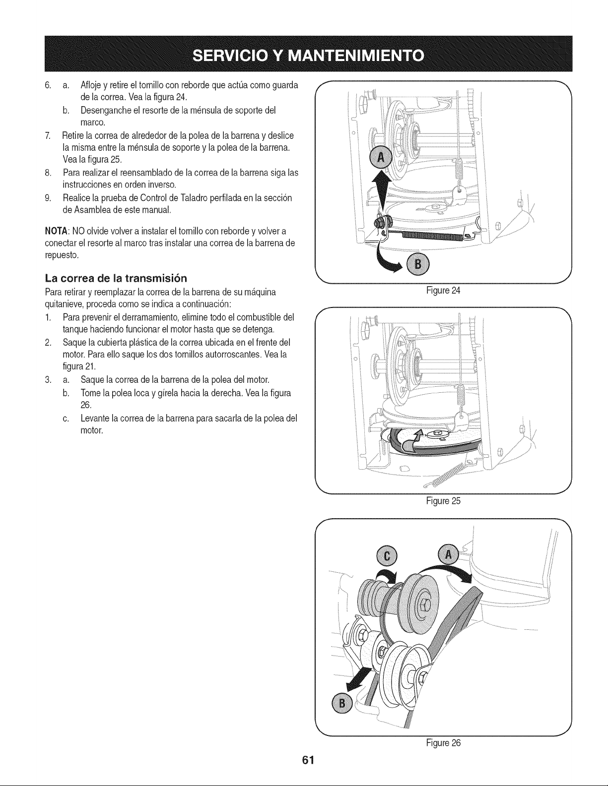
6. a. AflojeyretireeltornilloconrebordequeactOacomoguarda
delacorrea.Vealafigura24.
b. Desengancheelresortedelam_nsuladesoportedel
marco.
7. Retirelacorreadealrededordelapoleadelabarrenaydeslice
lamismaentrelam_nsuladesoporteylapoleadelabarrena.
Vealafigura25.
8. Pararealizarelreensambladodelacorreadelabarrenasigalas
instruccionesenordeninverso.
9. RealicelapruebadeControldeTaladroperfiladaenlasecci6n
deAsambleadeestemanual.
NOTA:NOolvidevolverainstalareltornilloconrebordeyvolvera
conectarelresortealmarcotrasinstalarunacorreadelabarrenade
repuesto.
La correa de la transmisi6n
Pararetirary reemplazarla correadela barrenade su m&quina
quitanieve,procedacomose indicaa continuaci6n:
1. Paraprevenirel derramamiento,eliminetodoel combustibledel
tanquehaciendofuncionarel motorhastaque sedetenga.
2. Saquela cubiertapl_.sticade la correaubicadaen el frentedel
motor.Paraello saquelosdos tornillosautorroscantes.Veala
figura21.
3. a. Saquela correade la barrenade la poleadelmotor.
b. Tomela polea Iocay girela hacialaderecha.Vealafigura
26.
c. Levantela correade la barrenaparasacarlade lapoleadel
motor.
Figure24
/" }
ioi
Figure25
,J
f
61
Figure26
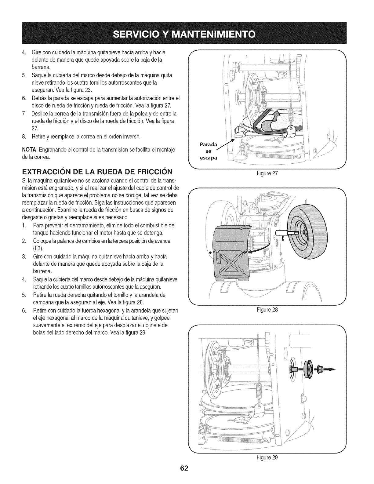
4. Gireconcuidadolarn&quinaquitanievehaciaarribayhacia
delantedernaneraquequedeapoyadasobrelacajadela
barrena.
5. Saquelacubiertadelmarcodesdedebajodelarn&quinaquita
nieveretirandoloscuatrotorniNosautorroscantesquela
aseguran.Vealafigura23.
6. Detr&slaparadaseescapaparaaurnentarlaautorizaci6nentreel
discoderuedadefricci6nyruedadefricci6n.Vealafigura27.
7. Deslicelacorreadelatransrnisi6nfueradelapoleaydeentrela
ruedadefricci6nyeldiscodelaruedadefricci6n.Vealafigura
27.
8. Retireyreernplacelacorreaenelordeninverso.
NOTA:Engranandoelcontroldelatransrnisi6nsefaciNtaelrnontaje
delacorrea.
EXTRACCI6N DE LA RUEDA DE FRICCI6N
Si la rn&quinaquitanieveno se accionacuandoel controlde la trans-
rnisi6nest&engranado,y sial realizarel ajustedel cablede controlde
latransrnisi6nque apareceel problernano se corrige,tal vez se deba
reernplazarla ruedadefricci6n.Sigalas instruccionesque aparecen
acontinuaci6n.Examinela ruedade fricci6nen buscade signosde
desgasteo grietas y reernplacesi es necesario.
1. Paraprevenirel derrarnarniento,elirninetodo el combustibledel
tanquehaciendofuncionarel motorhastaque se detenga.
2. Coloquelapalancade carnbiosen la terceraposici6nde avance
(F3).
3. Gire concuidadola rn&quinaquitanievehaciaarribay hacia
delantede rnaneraquequedeapoyadasobrela cajade la
barrena.
4. Saquela cubiertadel marcodesdedebajodelarnaquinaquitanieve
retirandoloscuatrotornillosautorroscantesquelaaseguran.
5. Retirela ruedaderechaquitandoel tornilloy la arandelade
carnpanaque la aseguranal eje. Veala figura28.
6. Retirecon cuidadola tuercahexagonaly laarandelaquesujetan
eleje hexagonalal marcode larn&quinaquitanieve,y golpee
suavernenteel extrernodel ejeparadesplazarel cojinetede
bolasdel ladoderechodel marco.Vealafigura29.
f
f
Parada
escapa
i° i
Figure27
i/
Figure28
J
Figure29
J
62
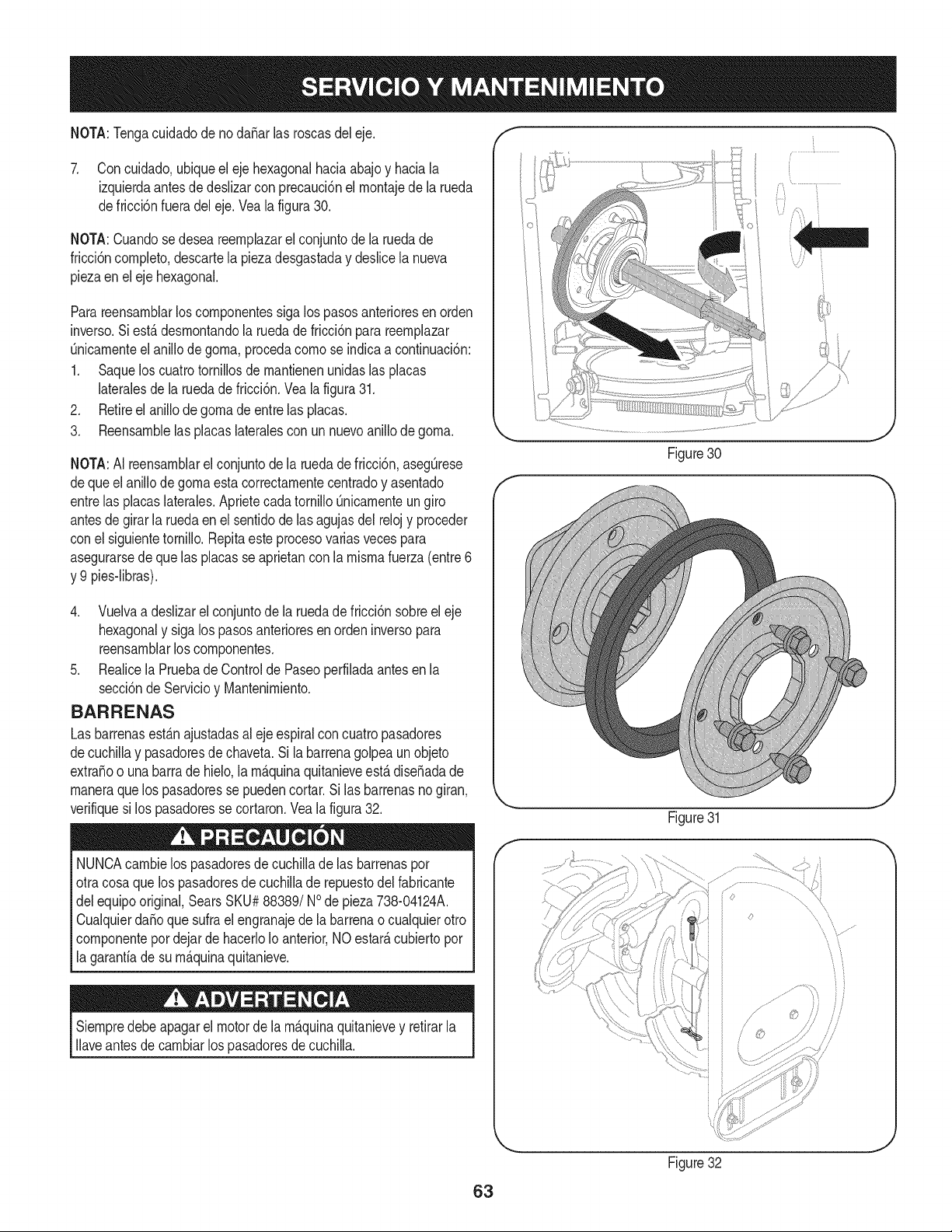
NOTA:Tengacuidadode nodaSarlas roscasdeleje.
7. Con cuidado,ubiqueel eje hexagonalhaciaabajoy haciala
izquierdaantesde deslizarcon precauci6nel rnontajede la rueda
defricci6nfueradel eje.Vealafigura30.
NOTA:Cuandosedesea reernplazarel conjuntode la ruedade
fricci6ncornpleto,descartela piezadesgastaday deslicela nueva
piezaen el ejehexagonal.
Parareensarnblarloscornponentessigalos pasosanterioresenorden
inverso.Si est,. desrnontandola ruedadefricci6npara reernplazar
Onicarnenteelanillode gorna,procedacornose indicaa continuaci6n:
1. Saquelos cuatrotornillosdernantienenunidaslas placas
lateralesde la ruedadefricci6n.Veala figura31.
2. Retireel anillode gornade entrelas placas.
3. Reensarnblelas placaslateralescon un nuevoanillode gorna.
NOTA:AI reensarnblarel conjuntode la ruedade fricci6n,asegOrese
dequeel anillode gornaestacorrectarnentecentradoy asentado
entrelas placaslaterales.AprietecadatornilloOnicarnenteun giro
antesde girar la ruedaenel sentidode lasagujasdel relojy proceder
conel siguientetornillo.Repitaeste procesovariasvecespara
asegurarsede que las placasse aprietancon la rnisrnafuerza(entre6
y 9 pies-libras).
4. Vuelvaa deslizarel conjuntode la ruedade fricci6nsobreel eje
hexagonaly sigalos pasosanterioresen ordeninversopara
reensarnblarloscornponentes.
5. Realicela Pruebade Controlde Paseoperfiladaantesen la
secci6nde Servicioy Mantenirniento.
BARRENAS
Las barrenasestAnajustadasalejeespiralcon cuatropasadores
decuchillay pasadoresde chaveta.Sila barrenagolpeaunobjeto
extraSoo una barrade hielo,la rn_.quinaquitanieveest,.diseSadade
rnaneraquelos pasadoresse puedencortar.Si las barrenasno giran,
verifiquesi los pasadoresse cortaron.Vea la figura32.
NUNCAcarnbielos pasadoresde cuchillade las barrenaspor
otracosa que lospasadoresdecuchillade repuestodel fabricante
delequipooriginal,SearsSKU#88389/NOde pieza738-04124A.
Cualquierda_o que sufra el engranajedela barrenao cualquierotro
cornponentepordejardehacerloIoanterior,NOestar_,cubiertopor
la garanfiade su rn_.quinaquitanieve.
Siernpredebeapagarel motorde la rn_.quinaquitanievey retirarla
Ilaveantesde carnbiarlos pasadoresdecuchilla.
f
Figure30
f
Figure31
63
Figure32
Sinosevaautilizaelequipodurante30dfasorn_.s,osieselfinaldelaternporadadenieveyyanoexisteposibilidaddequenieve,esnecesario
alrnacenarelequipodernaneraadecuada.Sigalasinstruccionesdealrnacenarnientoqueseindicanacontinuaci6nparagarantizarelrendirniento
rn_.xirnodelarn_.quinaquitanieveduranternuchosa_os.
PREPARACION DEL MOTOR
Yaquelos rnotoresalrnacenaronrn_.sde 30 dfas:
1. Irnpedira gornaforrnarseen sisternade combustibleo en partes
decarburadoresenciales:
a. Siel dep6sitode combustiblecontienela gasolinaoxigenada
oforrnuladade nuevo(gasolinarnezcladacon unalcoholo _ter),
dirijasel motor hastaque esto se parea faltadel combustible.
Aloscombustiblescon rnezcladealcohol(quese Ilarnangasohol,
oque utilizanetanolo rnetanol)puedenatraerla hurnedad,Io que
conducea la separaci6ny forrnaci6nde_.cidosduranteel alrnace-
narniento.Elgas acfdicopuededa_arel sisternadel combustiblede
unmotorduranteel alrnacenarnientodel rnisrno.
b. Siel dep6sitode combustiblecontienela gasolina,motordirigido
hastaqueestose parea falta del combustibleo a_ada un aditivo
degasoNnaal gasen el tanque.Si usted usaun aditivo degas,
dirigeel motordurantevariosrninutosparaponerencirculaci6nel
aditivoporelcarburador.
Nuncaalrnacenela rn_.quinaquitanievecon combustibleen el
tanqueen un espaciocerradoo en _.reascon pocaventilaci6n,
dondelos gasesdelcombustiblepuedanalcanzarel fuego,chispas
o una luz pilotocornola que tienenalgunoshornos,calentadoresde
agua,secadoresde ropao algQnotto dispositivoa gas.
PREPARACION DE LA iVlAQUINA QUITANIEVE
1. Cuandoalrnacenelarn&quinaquitanieveen ungalp6nde
dep6sitornet_.licoo con pocaventilaci6n,tengaespecialcuidado
de realizarleuntratarnientoanti- oxidanteal equipo.Useaceite
ligeroo silic6npara recubrirel equipo,especialrnentelas
cadenas,los resortes,loscojinetesy loscables.
2. Elirninetodo el polvodelexteriordelmotory delequipo.
3. Siga las recornendacionesde lubricaci6nen la secci6nde
mantenirnientode este manual.
4. Alrnaceneel equipoen un_.readespejaday seca.
.
3.
Mientrasel motor estodavfacaliente,carnbioel petr61eo.
Quitela bujfay manesobrela onza 1/2de petr61eode motorpor
elagujerode bujfaen el ciNndro.Sustituyala bujfay arranquecon
larnanivelael motorvariasvecesparadistribuirel petr61eo.
Nuncauseel motoro elcarburadorquelirnpiaproductosen el
dep6sitodecombustibleo el da_operrnanentepuedeocurrir.
64
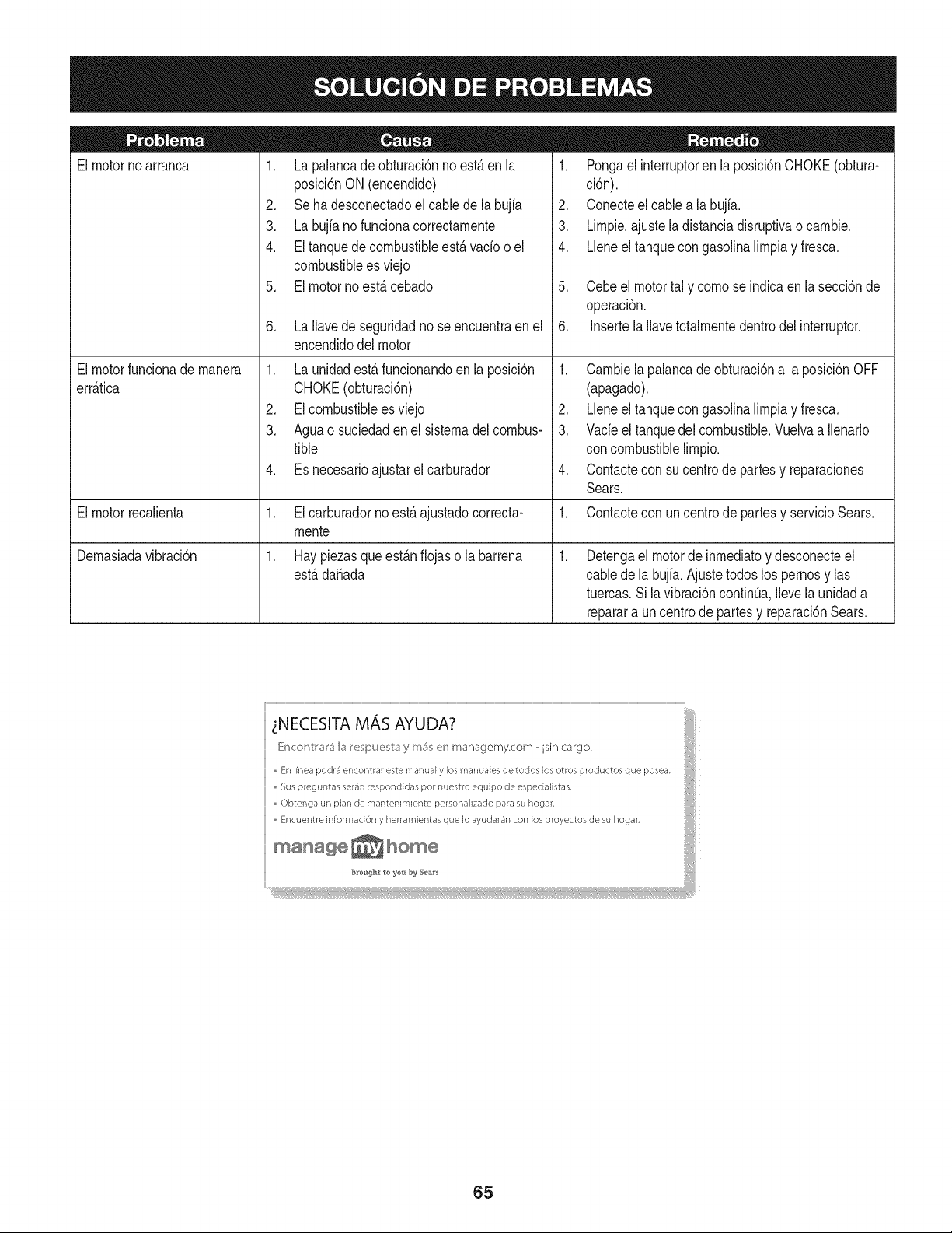
El motorno arranca
El motorfundonade manera
err_.fica
El motorrecalienta
Demasiadavibrad6n
1. La palancade obturaci6nno est,. en la
posici6nON(encendido)
2. Se ha desconectadoel cablede la bujia
3. La bujfano funcionacorrectamente
4. El tanquede combustibleest,.vado oel
combustiblees viejo
5. El motor no est,. cebado
6. La Ilavede seguridadno se encuentraen el
encendidodel motor
1. La unidadest,. funcionandoenla posici6n
CHOKE(obturaci6n)
2. EIcombustibleesviejo
3. Aguao suciedaden el sistemadel combus-
tible
4. Es necesarioajustarel carburador
1. El carburadornoest,.ajustadocorrecta-
mente
1. Hay piezasqueest_.nfiojaso la barrena
estB.dafiada
1. Pongael interruptorenlaposici6nCHOKE(obtura-
ci6n).
2. Conecteelcable a la bujfa.
3. Limpie.ajuste la distanciadisruptivao cambie.
4. Lleneel tanquecon gasolinalimpiay fresca.
5. Cebeel motortal y comose indicaenla secci6nde
operaci6n.
6. Insertela Ilavetotalmentedentrodelinterruptor.
1. Cambiela palancade obturaci6na la posici6nOFF
(apagado).
2. Lleneel tanquecon gasolinalimpiay fresca.
3. Vacieel tanquedel combustible.Vuelvaa Ilenarlo
concombustiblelimpio.
4. Contactecon sucentro de partesy reparaciones
Sears.
1. Contactecon un centrode partesy servicioSears.
Detengael motorde inmediatoy desconecteel
cablede la bujia.Ajustetodoslos pernosy las
tuercas.Si la vibraci6ncontinOa.Ilevela unidada
reparara uncentrode partesy reparaci6nSears.
LNECESITA MAS AYUDA?
[{:r_cmV:r_l'_ I_ I_!spu_;V:_ y m_; _!r_managemy.com -isin cargo!
_ En Iflqea podr_ er/contrar este manual y los rnanuales de todos los otros productos que posea.
os_p_egur,t_ _er_nre_pond_d_pornuest_oequ_pode_ped_st_, ii
Obtenga un plan de rT/antenimiento personalizade para su hogar.
o Encuentre informaci6n y herramientas que Io ayudar3n con les proyectos de su hogar,
i
65
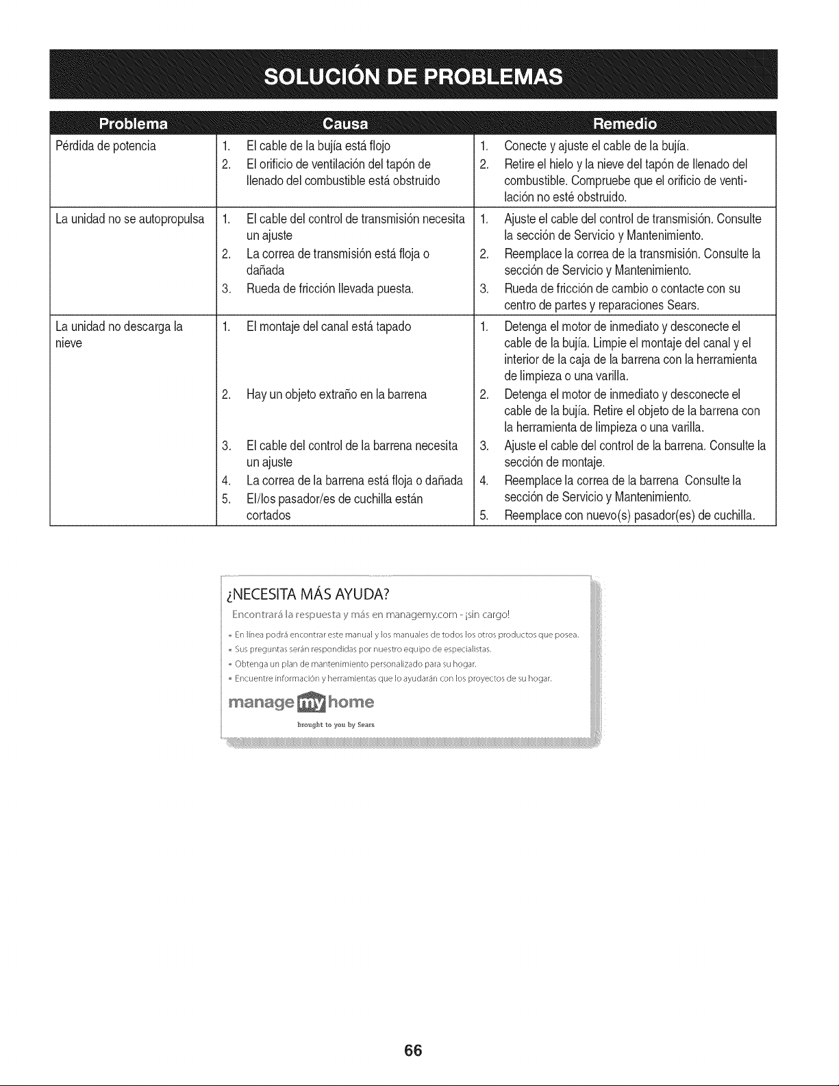
Perdidadepotencia 1. El cablede la bujfaest,.fiojo
2. El orificio de ventilaci6ndel tap6nde
Ilenadodel combustibleest,.obstruido
1. El cabledel controldetransrnisi6nnecesita
unajuste
2. La correade transrnisi6nest,.fiojao
daSada
3. Ruedadefricci6n Ilevadapuesta.
1. El rnontajedelcanalest,. tapado
2. Hay un objetoextraSoenla barrena
Elcabledel controlde labarrenanecesita
Launidadnose autopropulsa
Launidadnodescargala
nieve
unajuste
Lacorreade la barrenaest,.flojao daSada
El/lospasador/esde cuchillaest_.n
cortados
.
4.
5.
1. Conectey ajusteel cablede la bujfa.
2. Retireel hieloy la nievedeltap6nde Ilenadodel
combustible.Cornpruebequeel orificiode venti-
laci6nno est_ obstruido.
1. Ajusteel cabledelcontroldetransrnisi6n.Consulte
la secci6nde Servicioy Mantenirniento.
2. Reernplacela correade latransrnisi6n.Consultela
secci6nde Servicioy Mantenirniento.
3. Ruedade fricci6nde carnbioo contactecon su
centrode partesy reparacionesSears.
1. Detengael motorde inrnediatoy desconecteel
cablede labujia. Lirnpieel rnontajedel canaly el
interiorde lacaja dela barrenaconla herrarnienta
delirnpiezao unavarilla.
2. Detengael motorde inrnediatoy desconecteel
cablede labujia. Retireel objetode labarrenacon
la herrarnientadelirnpiezao unavarilla.
3. Ajusteel cabledelcontrolde la barrena.Consultela
secci6nde rnontaje.
4. Reernplacela correade la barrena Consultela
secci6nde Servicioy Mantenirniento.
5. Reernplacecon nuevo(s)pasador(es)de cuchilla.
66
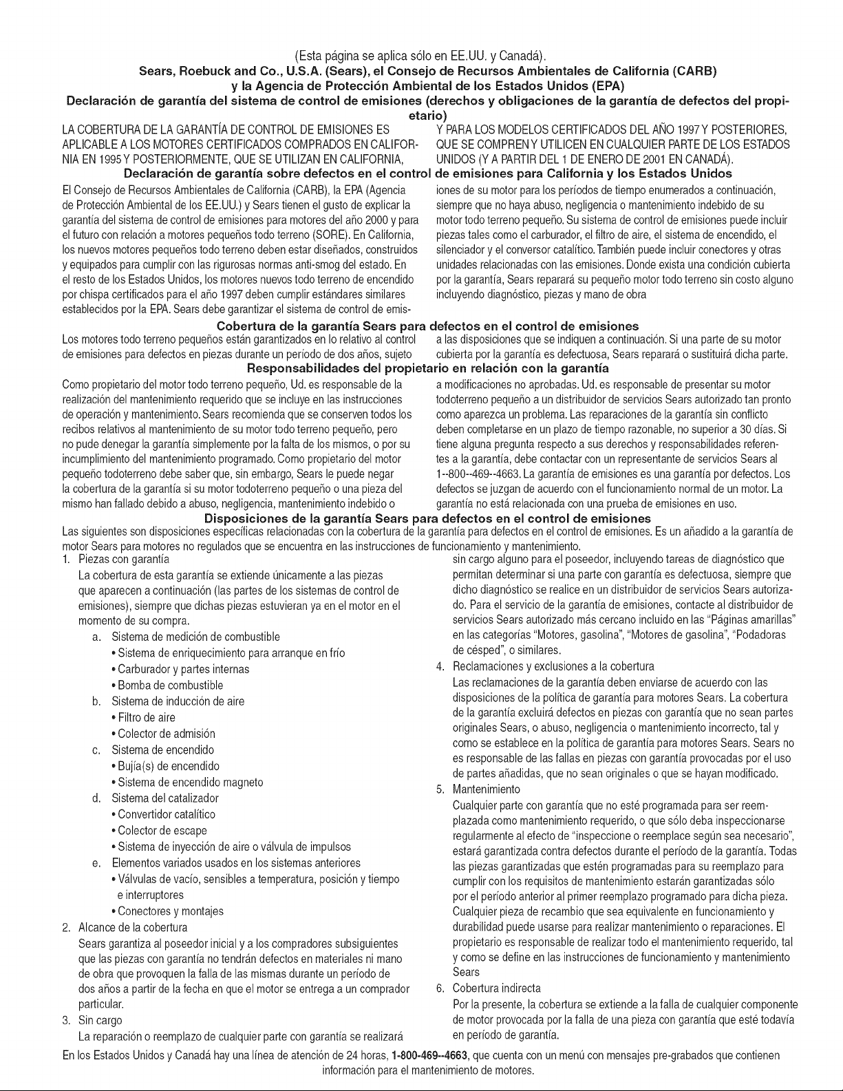
(Esta p_.ginase aplica s61oen EE.UU. y Canada.).
Sears, Roebuck and Co., U.S.A. (Sears), el Consejo de Recursos Arnbientales de California (CARB)
y la Agencia de Protecci6n Ambiental de los Estados Unidos (EPA)
Declaraci6n de garantia del sistema de control de emisiones (derechos y obligaciones de la garantia de defectos del propi=
etario)
LA COBERTURADELA GARANTJADE CONTROLDE EMISIONESES Y PARALOSMODELOSCERTIFICADOSDELANO 1997Y POSTERIORES,
APLICABLEA LOSMOTORESCERTIFICADOSCOMPRADOSEN CALIFOR-
NIA EN 1995YPOSTERIORMENTE,QUESE UTILIZANENCALIFORNIA,
Declaraci6n de garantJa sobre defectos en el control
ElConsejode RecursosAmbientalesde California(CARB),la EPA(Agencia
de Protecci6nAmbientalde los EE.UU.)y Searstienen elgustode explicarla
garantiadel sistemade control de emisionespara motoresdel a_o2000y para
elfuturocon relaci6na motorespeque_ostodo terreno(SORE).En California,
losnuevosmotorespeque6ostodo terrenodebenestar dise_ados,construidos
y equipadosparacumplircon las rigurosasnormasanti-smogdel estado.En
el restode losEstadosUnidos,losmotoresnuevostodoterrenode encendido
porchispa certificadosparael a_o 1997debencumplirest_ndaressimilares
establecidospot la EPA.Searsdebegarantizarel sistemade controlde emis-
QUESE COMPRENYUTILICENENCUALQUIERPARTEDELOS ESTADOS
UNIDOS(YA PARTIRDEL 1 DE ENERODE 2001 ENCANADA).
de ernisiones para California y los Estados Unidos
ionesdesu motorpara losperiodosde tiempoenumeradosa continuaci6n,
siemprequeno hayaabuso,negligenciao mantenimientoindebidode su
motortodoterrenopeque_o.Su sistemade controlde emisionespuedeincluir
piezastales comoel carburador,el filtro de aire,el sistemade encendido,el
silenciadoryel conversorcatalitico.Tambienpuedeincluirconectoresy otras
unidadesrelacionadascon las emisiones.Dondeexistaunacondici6ncubierta
porla garantia,Sears reparar_su peque6omotortodo terrenosin costoalguno
incluyendodiagn6stico,piezasy manodeobra
Cobertura de la garantJa Sears para defectos en el control de ernJsiones
Los motorestodo terrenopeque6osest_ngarantizadosen Iorelativoal control alas disposicionesque se indiquena continuaci6n.Si una partede su motor
de emisionespara defectosenpiezasduranteun periodode dos a_os,sujeto cubiertapot la garanfiaesdefectuosa,Sears reparar_o sustituir_dicha parte.
ResponsabJlidades del propietario en relacibn con la garantia
Comopropietariodel motortodo terrenopeque_o,Ud.es responsablede la
realizaci6ndel mantenimientorequeridoquese incluyeen las instrucciones
de operaci6ny mantenimiento.Searsrecomiendaquese conserventodoslos
recibosrelativosal mantenimientode su motortodoterrenopeque_o,pero
no pudedenegarlagarantiasimplementeporla faltadelosmismos,o por su
incumplimientodel mantenimientoprogramatic.Comopropietariodel motor
peque_otodoterrenodebe saberque, sinembargo,Searsle puedenegar
la coberturade la garantiasi su motortodoterrenopeque6oo una piezadel
mismohanfalladodebidoa abuso,negligencia,mantenimientoindebidoo
a modificacionesno aprobadas.Ud.es responsablede presentarsu motor
todoterrenopeque6oa un distribuidorde serviciosSearsautorizadotan pronto
comoaparezcaun problema.Lasreparacionesde la garantiasin confiicto
debencompletarseen un plazode tiempo razonable,no superiora 30 dias.Si
tienealguna preguntarespectoa sus derechosy responsabilidadesreferen-
tes a lagarantia,debe contactarcon un representantede serviciosSearsal
1--800--469--4663.Lagarantiade emisioneses unagarantiapordefectos.Los
defectossejuzgan de acuerdoconel funcionamientonormalde un motor.La
garantia no est_ relacionadacon unapruebade emisionesen uso.
Disposiciones de la garantJa Sears para defectos en el control de emisiones
Las siguientesson disposicionesespecificasrelacionadascon la coberturade lagarantia paradefectosen el controlde emisiones.Es un a_adidoa lagarantiade
motorSearspara motoresno reguladosque seencuentraen lasinstruccionesde funcionamientoy mantenimiento.
1. Piezascon garantia
La coberturade estagarantiase extiendeL]nicamentealas piezas
queaparecena continuaci6n(las partesde lossistemasde control de
emisiones),siempreque dichaspiezasestuvieranya en el motoren el
momentode su compra.
a. Sistemade medici6nde combustible
• Sistemade enriquecimientopara arranqueen frio
• Carburadory partesinternas
• Bombade combustible
b. Sistemade inducci6nde aire
• Filtrode aire
• Colectorde admisi6n
c. Sistemadeencendido
• Bujia(s)deencendido
• Sistemade encendidomagneto
d. Sistemadelcatalizador
• Convertidorcatalitico
• Colectorde escape
• Sistemade inyecci6nde aire o v_lvula de impulsos
e. Elementosvariadosusadosen los sistemasanteriores
• Wlvulas de vacio,sensiblesa temperatura,posici6ny tiempo
e interruptores
• Conectoresy montajes
2. AIcancede la cobertura
Searsgarantizaal poseedorinicial y a loscompradoressubsiguientes
que laspiezascongarantiano tendr_ndefectosen materialesni mano
de obra que provoquenla falla de las mismasduranteun periodo de
dos a6osa partirdela fechaen queel motorse entregaa un comprador
particular.
3. Sin cargo
La reparaci6no reemplazodecualquierpartecon garantia se realizar_
sin cargoalgunoparael poseedor,incluyendotareasde diagn6sticoque
permitandeterminarsi una partecon garantiaes defectuosa,siempreque
dichodiagn6sticose realiceen undistribuidorde serviciosSears autoriza-
do. Parael servicio de lagarantia deemisiones,contacteal distribuidorde
serviciosSearsautorizadom_scercanoincluidoen las"P_ginasamarillas"
en lascategorias"Motores,gasolina","Motoresde gasolina","Podadoras
de cesped",o similares.
4. Reclamacionesy exclusionesa la cobertura
Las reclamacionesde lagarantiadebenenviarsede acuerdo con las
disposicionesde la politica de garantia paramotoresSears.La cobertura
de la garantiaexcluir_defectosen piezascon garantiaque no scan partes
originalesSears,o abuso, negligenciao mantenimientoincorrecto,tal y
como se estableceenla politica degarantia paramotoresSears.Sears no
es responsablede lasfallas en piezas con garantia provocadaspor el uso
de partesaSadidas,que no scan originaleso quese hayan modificado.
5. Mantenimiento
Cualquierpartecon garantiaque no este programadaparaserreem-
plazadacomomantenimientorequerido,o que s61odeba inspeccionarse
regularmenteal efecto de"inspeccioneo reemplacesegL]nsea necesario",
estar_garantizadacontradefectosduranteel periodode la garantia.Todas
laspiezasgarantizadasque esten programadaspara su reemplazopara
cumplircon los requisitosde mantenimientoestar_ngarantizadass61o
porel periodoanterior al primerreemplazoprogramaticparadicha pieza.
Cualquierpiezade recambioquesea equivalenteen funcionamientoy
durabilidadpuedeusarse para realizarmantenimientoo reparaciones.El
propietarioes responsablede realizartodo elmantenimientorequerido,tal
y comose define en las instruccionesde funcionamientoy mantenimiento
Sears
6. Coberturaindirecta
Porla presente,la coberturase extiendea lafalla decualquiercomponente
de motorprovocadapor lafalla de unapieza con garantia queestetodavia
en periodode garantia.
En los EstadosUnidosy Canad_hayunalinea de atenci6nde 24 horas,1-800-469--4GG3,quecuentaconun menL]con mensajespre-grabadosque contienen
informaci6npara el mantenimientode motores.
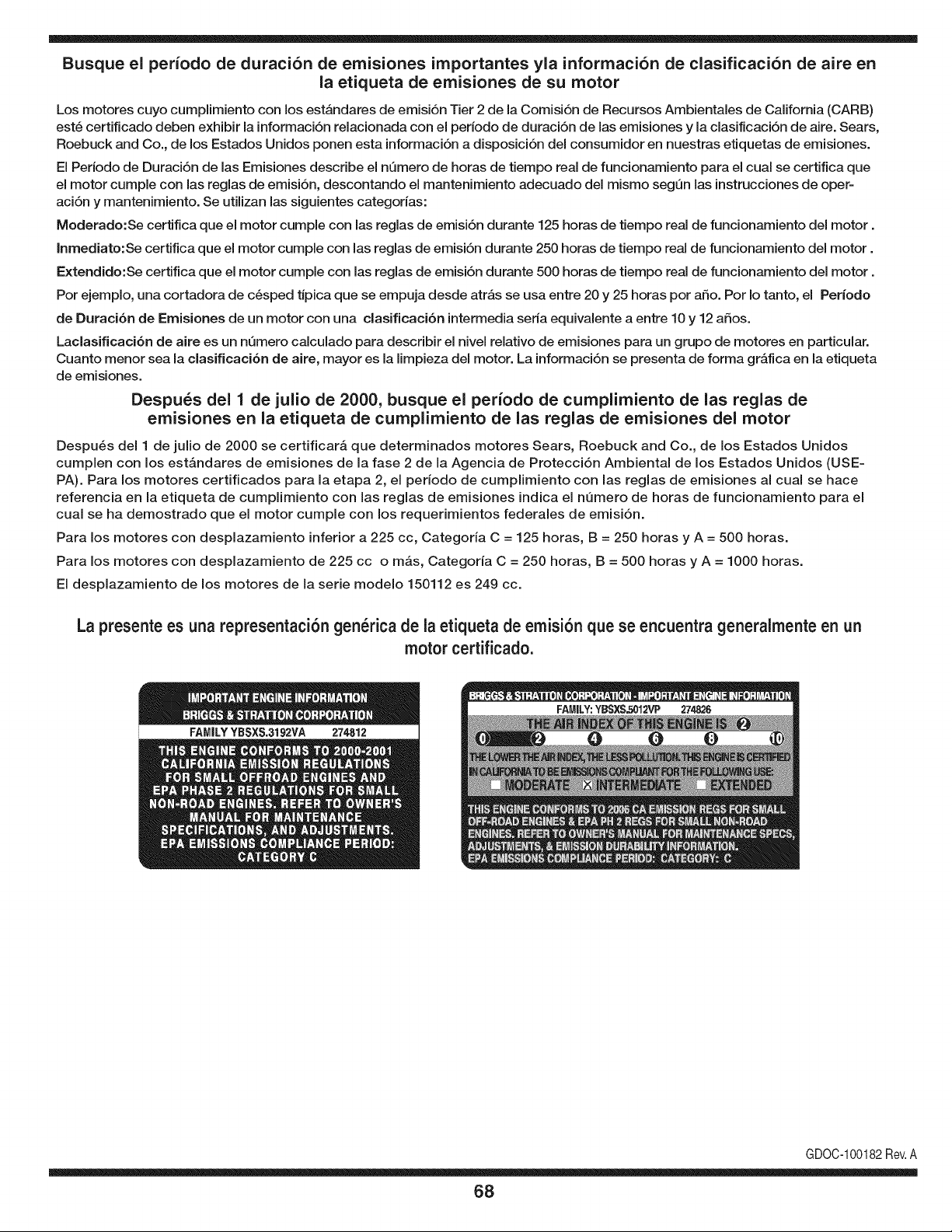
Busque el periodo de duraci6n de emisiones importantes yla informaci6n de clasificaci6n de aire en
la etiqueta de emisiones de su motor
Los motores cuyo cumpiimiento con los estAndares de emisi6n Tier 2 de la Comisi6n de Recursos Ambientales de California (CARB)
est6 certificado deben exhibir la informaci6n relacionada con el perJodo de duraci6n de las emisiones y la clasificaci6n de aire. Sears,
Roebuck and Co., de los Estados Unidos ponen esta informaci6n a disposici6n deJ consumidor en nuestras etiquetas de emisiones.
El Periodo de Duraci6n de las Emisiones describe el nQmero de horas de tiempo real de funcionamiento para el cual se certifica que
el motor cumple con las reglas de emisi6n, descontando el mantenimiento adecuado deJ mismo segQn las instrucciones de oper-
aci6n y mantenimiento. Se utilizan las siguientes categorias:
Moderado:Se certifica que el motor cumpie con las reglas de emisi6n durante 125 horas de tiempo real de funcionamiento deJ motor.
Inmediato:Se certifica que el motor cumple con las reglas de emisi6n durante 250 horas de tiempo real de funcionamiento deJ motor.
Extendido:Se certifica que el motor cumple con las reglas de emisi6n durante 500 horas de tiempo real de funcionamiento deJ motor.
Por ejemplo, una cortadora de c6sped tJpica que se empuja desde atrAs se usa entre 20 y 25 horas por afio. Por Io tanto, el Periodo
de Duraci6n de Emisiones de un motor con una clasificaci6n intermedia seria equivalente a entre 10 y 12 afios.
Laclasificaci6n de aJre es un nQmero calculado para describir eJnivel reiativo de emisiones para un grupo de motores en particular.
Cuanto menor sea Jaclasificaci6n de aire, mayor es JaJimpieza deJ motor. La informaci6n se presenta de forma gr&fica en Jaetiqueta
de emisiones.
Despu_s del 1 de julio de 2000, busque el periodo de cumplimiento de las reglas de
emisiones en la etiqueta de cumplimiento de las reglas de emisiones del motor
Despu_s deJ 1 de julio de 2000 se certificar_, que determinados motores Sears, Roebuck and Co., de los Estados Unidos
cumpien con los estAndares de emisiones de la fase 2 de la Agencia de Protecci6n Ambiental de los Estados Unidos (USE-
PA). Para los motores certificados para la etapa 2, el periodo de cumpiimiento con las reglas de emisiones al cual se hace
referencia en la etiqueta de cumpiimiento con las reglas de emisiones indica el nQmero de horas de funcionamiento para el
cuaJ se ha demostrado que el motor cumpie con los requerimientos federales de emisi6n.
Para los motores con desplazamiento inferior a 225 cc, Categoria C = 125 horas, B = 250 horas y A = 500 horas.
Para los motores con desplazamiento de 225 cc o mAs, Categoria C = 250 horas, B = 500 horas y A = 1000 horas.
El despiazamiento de los motores de la serie modelo 150112 es 249 cc.
La presente es una representaci6n gen_rica de la etiqueta de emisi6n que se encuentra generaimente en un
motor certificado.
FAMILYYBSXS.3192VA 274812
GDOC-100182Rev.A
68
Felicitacionespor haberrealizadouna adquisici6ninteligente.El
productoCraftsman@queha adquiridoest_ dise_adoy fabricado
parabrindarrnuchosa_osde funcionarnientoconfiable.Perocorno
todoslos productosa vecespuederequerirde reparaciones.Esen
esernornentocuandoel disponerde unAcuerdode protecci6npara
reparacionesle puedeahorrardineroy problernas.
A continuaci6nsedetallanlos puntosincluidosenel Acuerdo:
• Servicio experto prestadopornuestros10,000especialistasen
reparacionesprofesionales
• Servicio ilirnitadosin cargopara laspiezasy la rnanodeobraen
todaslas reparacionescubiertas
• Reernplazodel productohasta1500d61aressi no es posible
repararel productocubierto
• Descuentode 10%del precionormaldel servicioy delas piezas
relacionadascon el rnisrnoqueno est_ncubiertasporel acuerdo;
adern&s,10%del precionormalde la verificaci6nde rnanten-
irnientopreventivo
• Ayudar_pidapottel_fono- IoIlarnarnosResoluci6nR_pida- el
apoyotelef6nicode un Charnuscaal representante.Pienseen
nosotroscornoel manual"de undue_ohablador."
Unavezadquiridoel Acuerdo,puedeprograrnarel serviciocon
tan s61orealizarunaIlarnadatelef6nica.PuedeIlarnarencualquier
mornentodeldia o dela nocheo prograrnarun servicioen linea.
ElAcuerdode Protecci6nde Reparaci6nes unacornprasin riesgo.
Siustedanulaporalgunaraz6nduranteel periodode garantiade
producto,proporcionarernosun reernbolsoIleno.O,un reernbolso
prorrateadoen cualquiermornentodespu_sdel periodode garantia
de productoexpira, iAdquieraboysu acuerdode protecci6npara
reparaciones!
Seaplican deterrninadaslirnitaciones y exclusiones.Paraobtener
inforrnaci6nadicional y preciosen los Estados UnidosIlarne al
1-800-827-6655.
El*Coverage en Canad_variaen algunosarticulos. Paradetalles
Ilenosla IlarnadaCharnuscaCanad_en 1-800-361-6665.
Servicio de instalaci6nde Sears
Sideseasolicitarla instalaci6nprofesionalde Searsde aparatos
dorn_sticos,dispositivosparaabrirportones,calentadoresde agua
y otrosarficulosdorn_sticosirnportantes,en los EstadosUnidoso
Canad_Ilarneal 1-800-4-MY-HOME®.
69

70

71

Your Home
For expert troubleshooting and home solutions advice:
www.managemyhome.com
For repair - in your home - of all major brand appliances,
lawn and garden equipment, or heating and cooling systems,
no matter who made it, no matter who sold it!
For the replacement parts, accessories and
owner's manuals that you need to do-it-yourself.
For Sears professional installation of home appliances
and items like garage door openers and water heaters.
1-800-4-MY-HOME ® (1-800-469-4663)
Call anytime, day or night (U.S.A. and Canada)
www.sears.com www.sears.ca
Our Home
For repair of carry-in items like vacuums, lawn equipment,
and electronics, call anytime for the location of your nearest
Sears Parts & Repair Service Center
1-800-488-1222 (U.S.A.) 1-800-469-4663 (Canada)
www.sears.com www.sears.ca
To purchase a protection agreement on a product serviced by Sears:
1-800-827-6655 (U.S.A.) 1-800-361-6665 (Canada)
Para pedir servicio de reparaci6n
a domicilio, y para ordenar piezas:
1-888-SU-HOGAR ®
(1-888-784-6427)
Au Canada pour service en fran£ais:
1-800-LE-FOYER M°
(1-800-533-6937)
www.sears.ca
® Registered Trademark / TMTrademark / SM Service Mark of Sears Brands, LLC
SM
® Marca Registrada / TMMarca de F&brica / Marca de Servicio de Sears Brands, LLC
MCMarque de commerce / MD Marque depos6e de Sears Brands, LLC © Sears Brands, LLC