INSTALLATION AND
INSTRUCTION MANUAL
WIRELESS CLIMATE CONTROLLER
BROMIC STRATOS BRAHMA 3.0 / 5.0 / 7.0 / 9.0
Nov 2019-v1.0
BROMIC.COM/PLUMBING
1300 276 642
A member of the Bromic Group
o
Stratos Brahma

Wireless Controller - Instruction Manual
2
Flued Indoor Gas Heater - Instruction Manual
2
July 2019 - V1
PLUMBING & GAS
2
GENERAL
COMPLIANCE
RANGE
2
GENERAL
COMPLIANCE
RANGE
2
GENERAL
COMPLIANCE
RANGE
Head Ofce: 10 Phiney Place, Ingleburn, Sydney, NSW 2565 Australia
Telephone: 1300 276 642 (within Australia) or NZ 0508 276 642
Email: [email protected] Web: www.bromic.com/plumbing
Note: Bromic Plumbing Pty Ltd reserves the right to make changes to specications, parts,
components and equipment without prior notication. This Installation, operation and service manual
may not be reproduced in any form without prior written consent from Bromic Plumbing Pty Ltd.
This manual contains important information about the assembly, operation, and maintenance of
Blow Heaters. Please pay close attention to the important safety information shown
throughout this instruction manual. Any safety information will be accompanied
by the following safety alert symbols:
DANGER, WARNING, IMPORTANT
!
!
!
MODEL CODE
BRAHMA STRATOS 3.0 NG 2620970
BRAHMA STRATOS 5.0 NG 2620971
BRAHMA STRATOS 7.0 NG
2620972
BRAHMA STRATOS 9.0 NG 2620973
BASIC SAFETY PRECAUTIONS 3
GENERAL PRECAUTIONS 4
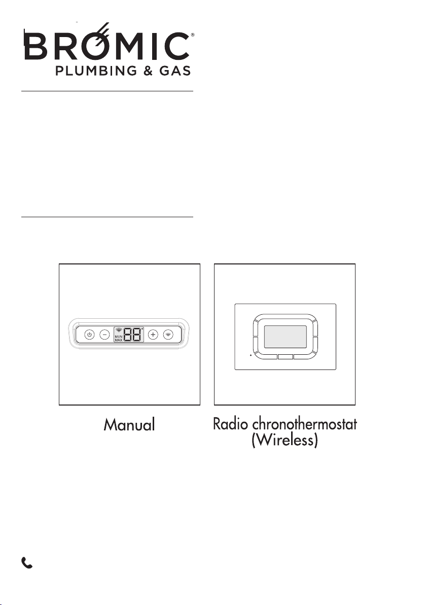
MORE ABOUT THE MANUAL CONTROL 5
Description of keys 5
Description of display 5
Programming 5
USING THE WIRELESS CONTROL 11
Description of keys 12
Programming 12
COMMISSIONING 21
SWITCHING OFF FOR LONG PERIODS 23
CLEANING THE APPLIANCE 23
MAINTENANCE 24
TROUBLESHOOTING 24
The appliance purchased by you
is covered by a SPECIFIC WARRANTY
starting on the date of validation by the Authorised
After-Sales Service in your area.
To find this log into our Website or phone
the manufacturer directly.
You are therefore warmly invited to promptly
contact the above After-Sales Service of the
Manufacturer which
FREE OF CHARGE
• will perform initial appliance start-up
• will validate the WA
RRANTY CERTIFICATE
provided with the appliance and which
you are invited to carefully read.
The After-Sales Service will offer suggestions
on how to use the appliance correctly
Our appliances are
in conformity with:
• Gas Directive 2009/142/CE
• Electromagnetic Compatibility Directive 2004/104/CE
• Low-Voltage Directive 2006/95/CE
0476
In some parts of the manual, the following symbols are used:
IMPORTANT = jobs requiring special caution and adequate preparation.
FORBIDDEN = jobs that MUST NOT be performed.
���

Wireless Controller - Instruction Manual
3
BASIC SAFETY PRECAUTIONS
Please remember that certain basic safety pre-
cautions must be taken when using products
requiring fuels and electricity:
- The appliance must not be used by children
and disabled persons if unassisted.
- If you smell fuel, do not start electric
appliances or appliances such as switches,
household appliances, etc.
In this case:
• ventilate the premises by opening the doors
and windo
ws;
• close the fuel opening/closing device;
• promptly call the After-Sales service or pro-
fessionally qualified personnel.
- Do not touch the appliance with wet or
damp parts of the body or if your feet are wet.
- Cleaning is forbidden without first discon-
necting the appliance from the power mains.
- Do not pull, disconnect or twist the power
cables exiting from the appliance even when
this is disconne
cted from the power mains.
- Do not place objects, curtains, etc., on the
appliance which could cause malfunctions or
prove to be a hazard.
4

Wireless Controller - Instruction Manual
4
5
GENERAL INFORMATION
This booklet and that for the Installer and
After-Sales Centre are an integral part of the
appliance and consequently must be looked
after carefully and ALWAYS accompany it even
when it is transferred to another owner or user
or to another system.
In the event of its being damaged or lost, ask
your Authorised Local Technical Centre for
another copy.
The appliance must be used as intended
by the Manufacturer for the purpose for
which it was specifically made.
The Manufacturer disclaims all contractual and
non-contractual liability for injury caused to
persons and animals and damage to things
caused by installation, adjustment and mainte-
nance errors or by improper use of the appli-
ance.
The appliance must be installed by a com-
pany approved in accordance with Law no. 46
dated 5 March 1990
which, once installation
has been made, must issue a correct installation
conformity certificate, pursuant to applicable
national and any local regulations in accor-
dance with Art. 17 of law no. 46/90 and the
instructions provided by the Manufacturer in the
installer's booklet provided with the product.
- If the appliance is not used for a long
period of time, the following operations must
be performed:
•
position the master switch of the system, if fit-
ted, on "off" or remove the plug from the mains
power socket;
• close the fuel tap.
Wireless Controller - Instruction Manual
5
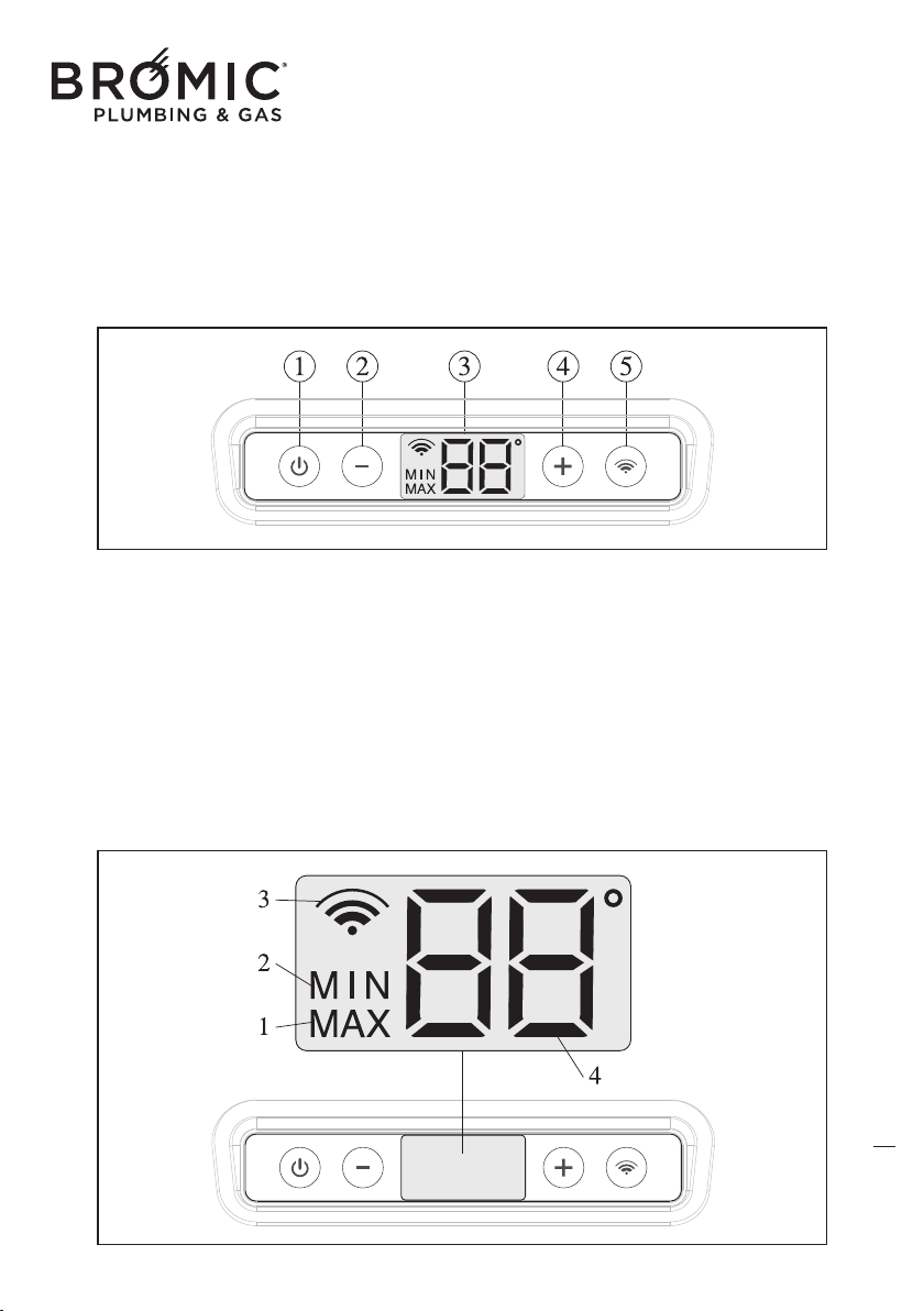
DESCRIPTION OF DISPLAY
This type of screen simultaneously provides an
entire series of information:
- MIN operating power.
- MAX operating power.
- Wire command enabling.
- ambient temperature.
- desired ambient temperature.
- degrees centigrade unit scale.
- data transmission
DESCRIPTION OF ICONS
1 - operation at MAX power.
2 - operation at MIN power.
3 - data transmission between the device and
the Wireless
command (intermittent icon).
3b - Wireless command enabled (fixed on
icon).
4 - Detected ambient temperature.
4b - Desired ambient temperature.
6
KNOW MANUAL COMMAND
1 - On/Off key and device RESET
2 - Reduce temperature key (MIN 5°C)
3 - Light display
4 - Increase temperature key (MAX 35°C)
5 - Enable/disable Wireless command key
Wireless Controller - Instruction Manual
6
PROGRAMMING
In the event of a power cut, the command main-
tains in the memory the operating status (normal or
with ERROR CODE), when electrical power returns
the previous operation continues.
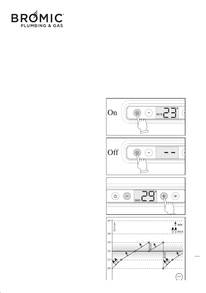
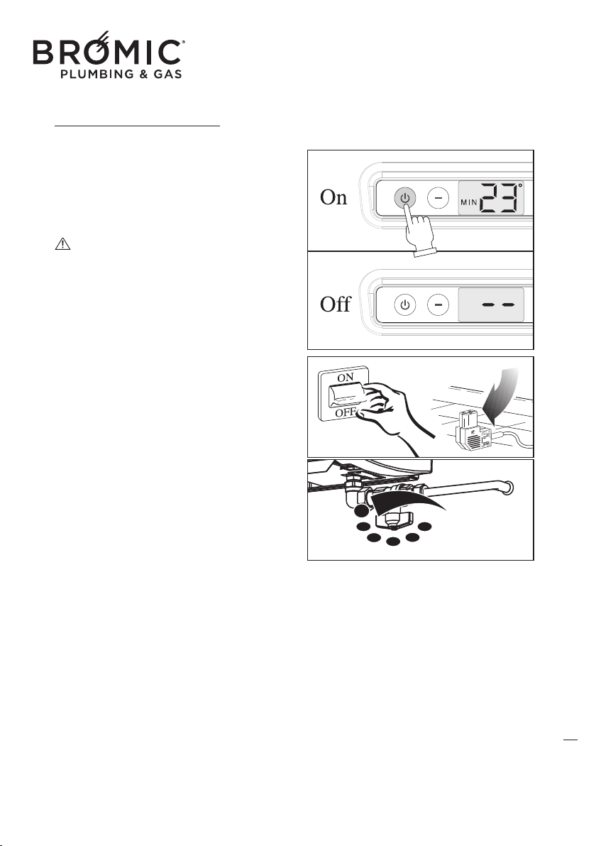
• START-UP
- Press the On/Off key, the display lights up and
the device starts.
The display is backlit only when the command is
used. It switches off automatically after approxi-
mately 3 seconds.
• SWITCH-OFF
- Press t
he On/Off key, the display lights up and
the device switches off.
The display is backlit only when the command is
used. It switches off automatically after approxi-
mately 3 seconds.
• TEMPERATURE ADJUSTMENT
With the device on:
- Press the “+” or “-”key, the display lights up to
flash the temperature which is already set.
- Press the “+” or “-” key to set the new desired
temperature.
With the device off:
- Pr
ess the “+” or “-”key, the display lights up to
flash the temperature which is already set.
- Press the “+” or “-” key to set the new desired
temperature which will be enabled as soon as the
device switches on.
A degree before (-1°) reaching the desired tempe-
rature, the device passes from MAX to MIN
power in automatic mode. Instead, if the desired
temperature is exceeded by a degree (+1°), the
device sto
ps.
7
Wireless Controller - Instruction Manual
7
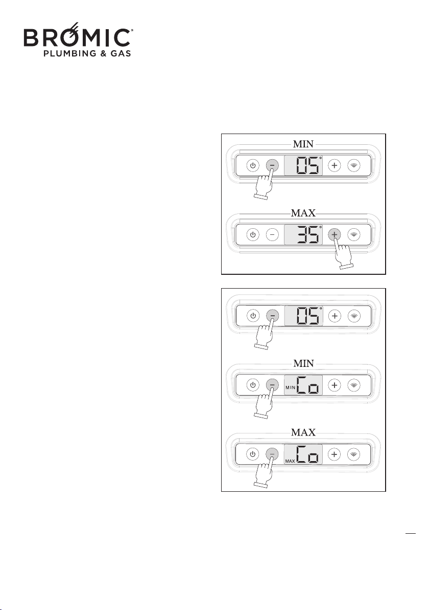
Temperature adjustment determines the type of
device operation: heating or summer ventilation.
HEATING
This function allows an operating temperature that
starts from 5°C to 35°C.
- Press the On/Off key.
- Press the “+” or“-” key to choose the desired tem-
perature.
SUMMER VENTILATION
(only managed by wireless command)
This function only uses the tangential fan at MIN or
MAX power and activates under 5°C.
- Pr
ess the On/Off key.
- Press the “-” key to set the temperature at 5°C.
- Press the “-” key to go under 5°C and then choose
the desired speed of the fan (MIN or MAX).
- Press the “+” key to bring the temperature over
5°C and exit summer ventilation.
8
Wireless Controller - Instruction Manual
8
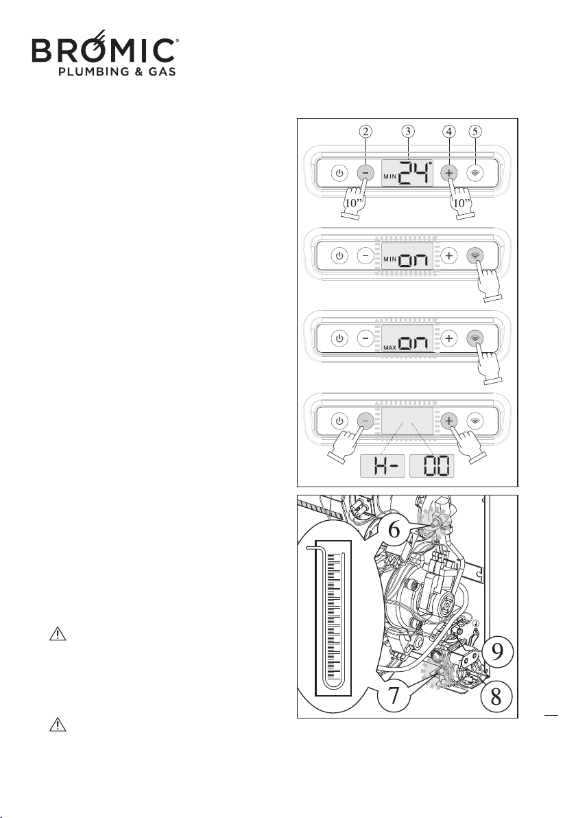
• HIDDEN FUNCTIONS: MIN POWER - MAX
POWER - SLEEP TIMER
This hidden function enables adjustment of the MIN
and MAX power level (only for Technical Support),
by doing so any ambient probe fault is ignored
and the burner function is forced to check the mod-
ulation parameters. The SLEEP TIMER function (for
the User) enables setting the device automatic
switch-off.
With the burner on or off:
- Connect the gaug
e on the device.
- Press “+” and “-” (2 + 4) together for MIN 10
seconds.
- “ON” and MIN appear on the display, set the
MIN pressure by rotating the adjustment screw (9)
on the valve.
- Press the “Wireless” key (5) to continue.
- “ON” and MAX appear on the display, set the
MAX pressure by rotating the adjustment screw (8)
on the valve.
- Press the “Wireless” key to continue.
- On the display “H-” and “00” ap
pear flashing alter-
natively (operating hours set, Sleep Timer function).
With the Sleep Timer function enabled, you can
change the temperature and switch off the
device.
- Press “+” or “-” to set the number of operating
hours (from MIN 1 to MAX 12).
- Press the “Wireless” key to continue.
- Press “+” and “-” together (2 + 4) for MIN 10
seconds to save the modified parameters and exit
the Hidden Function.
T
he “hidden function” is timed, after 0 min-
utes without pressing any key and without con-
firming the new values (“+” and “-” keys togeth-
er for MIN 10 seconds), the device exits program-
ming and maintains the previous values.
Sleep Timer, once inserted this function
always stays on and on each switch-on of the
device, to disable it, simply enter the Hidden
Functions and set the number of hours to “00”
.
9
Wireless Controller - Instruction Manual
9
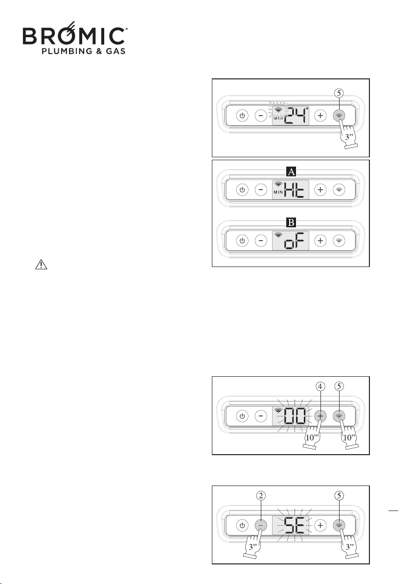
• WIRELESS COMMAND ENABLING
- Switch on the device.
- Activate the Wireless command inserting the batteries.
- Press the Wireless key (5) for MIN 3”, the wire-
less icon flashes.
- The device searches the nearest Wireless com-
mand, as soon as it finds it, it is automatically recog-
nised and the wireless icon remains on and fixed.
From now on, the device is managed by the wire-
less command and there will
be two types of
screens:
--- A (device on), HT (Heating) and MIN or MAX
(power).
--- B (device in stand-by), OF (Off), the device is
not off but in standby for the wireless command to
re-activate it to reach the desired temperature.
If communication between the device and the
remote chronothermostat is interrupted for more
than 5 seconds (e.g. battery discharge), the
device goes in standby while waiting fo
r a new
wireless signal. The device never disconnects
from the remote chronothermostat until the user
decides to do so.
• ASSIGN WIRELESS ADDRESS
- Switch on the device.
- At the same time press the 4 + 5 keys for 10 sec-
onds, the digits “00” flashes.
- Press the “+” and “-”keys to set the same value
already assigned to the remote chronothermostat.
- Press the 4 + 5 keys for 10 seconds to confirm
and return
to the main menu.
• KEYPAD LOCK
- Switch on the device.
- Simultaneously press the 2 + 5 keys for 3 sec-
onds, the letters “SE” (security) flash, whatever key
is pressed “SE” appears.
- At the same time, press the 2 + 5 keys for 3 sec-
onds to release the keys.
10
Wireless Controller - Instruction Manual
10
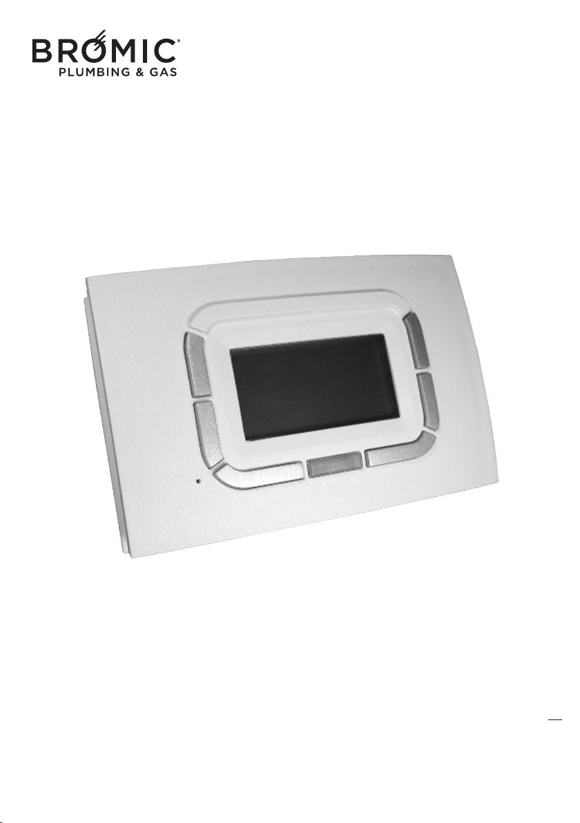
11
Wireless radio chronothermostat
WIRELESS
(optional, can also be purchased subsequently)
For the use and control of all gas appliances
in the range made by the Manufacturer.
Wireless Controller - Instruction Manual
11
-Carefully read the following instructions as these provide important information on installa-
tion and correct use of the Remote Control.
-The installer is kindly asked to give this booklet to the end user and to invite him/her to read
its contents.
-In case of malfunction or faults during the warranty period, contact the Manufacturer’s
Authorised Technical Assistance Centre only.
12
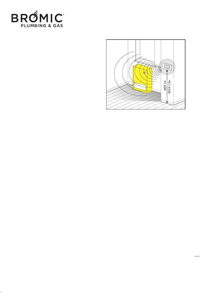
ABOUT THE RADIO WIRELESS CHRONOTHERMOSTAT
The use of this control allows:
- the best positioning of the detection sensor (on wall or table base) for controlling the actual room temperature;
- the possibility of controlling several appliances in the same room;
- programming daily and weekly operation.
Wireless radio chronothermostat without wires:
- one of a kind as regards ease of use and the control of
all the operating modes;
- distinguished by a large graphic Display unit that helps the user to make the various control and
adjustment settings;
- uses an “NTC” sensor that allows controlling/setting even the smallest room temperature variations (0.5°C),
while maintaining the difference in temperature, between switch-off and switch-on, within about 1°C.
Can also be purchased and used in a previously-i
nstalled appliance.
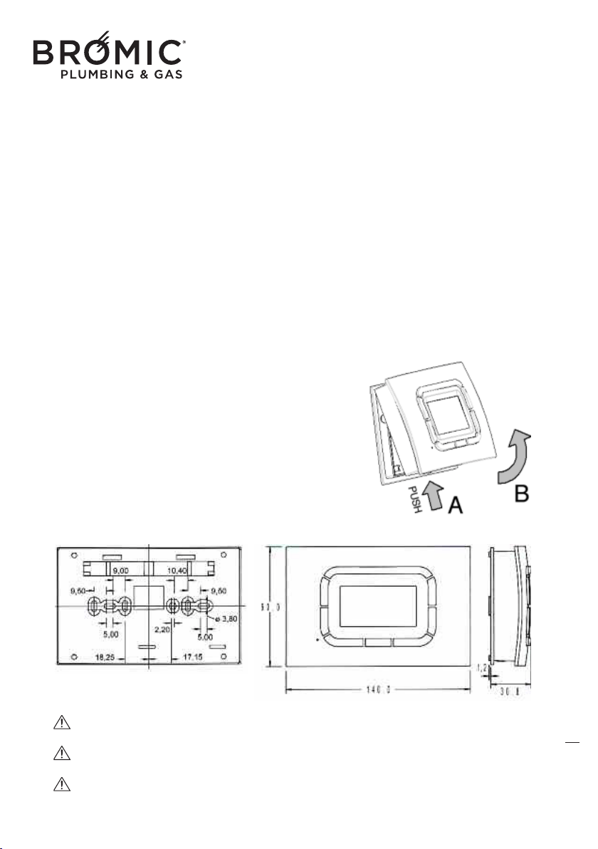
DIMENSIONS AND INSTALLATION
To install the chronothermostat, you need to:
- release the front with the display keeping the
hook pressed (PUSH key) then rotate upwards
separating it from the rear.
- mark and create holes and fasten the chro-
nothermostat on the wall.
- re-assemble the front with a compass movement,
but downwards until you hear a locking CLICK.
Wireless Controller - Instruction Manual
12
13
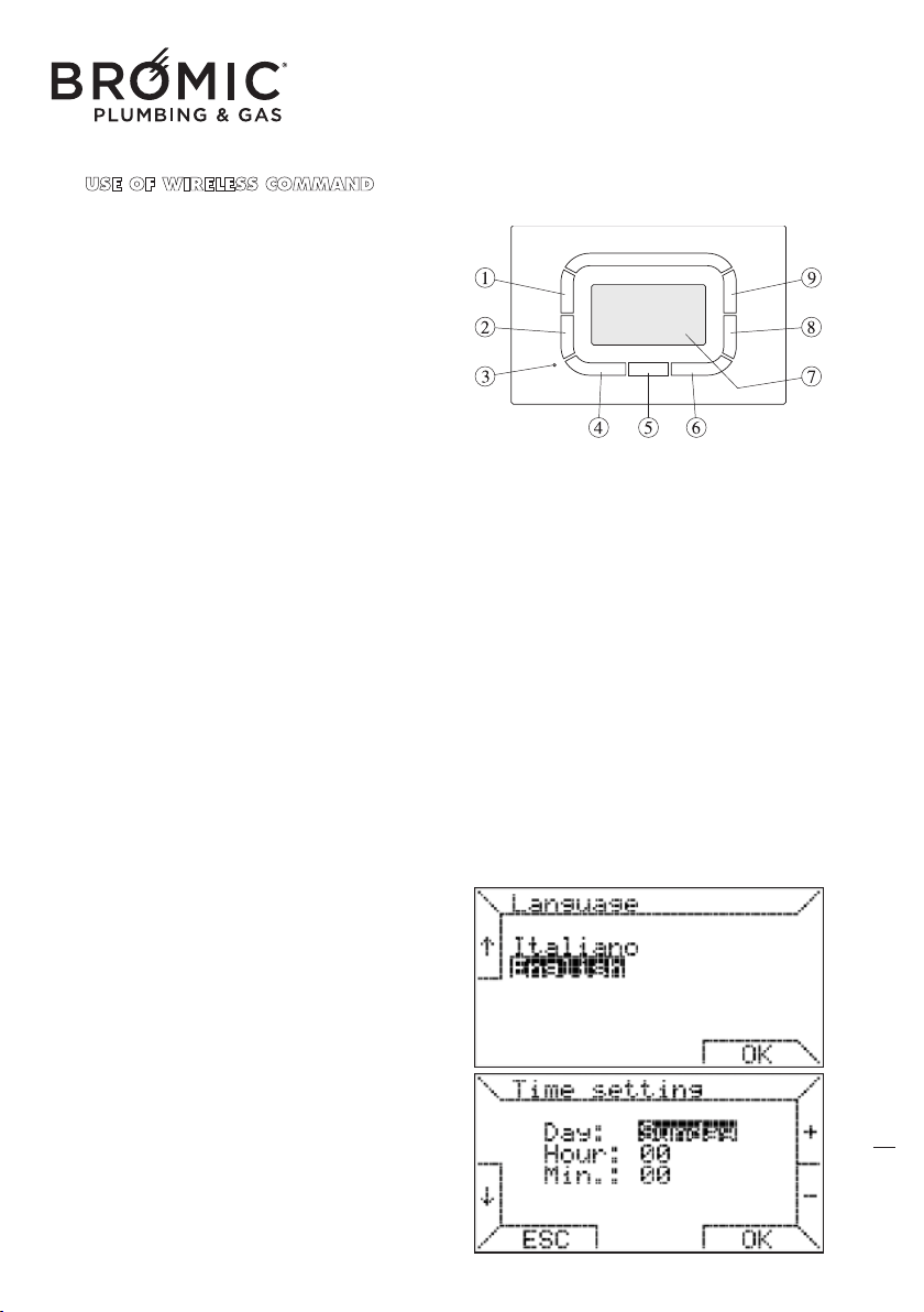
USE OF WIRELESS COMMAND
DESCRIPTION OF THE KEYS
1 - Function/parameter selection key
2 - Function/parameter selection key
3 - Reset
4 - Function key (NO, ESC, etc.)
5 - Multi-function transparent key
6 - Function key (OK, VENT, etc.)
7 - Display
8 - Temperature DECREASE key
9 - Temperature INCREASE key
GENERAL FEATURES
- Exclusive design
- graphic LCD 128x64 pixel
- timed backlighting 10 s
- LED for diagnostics/signals
- 7 variable function
keys
- weekly programming
- 4 temperature levels (T0, T1, T2, T3)
- settable ambient temp resolution: 0.5°C
- measured ambient temp resolution: 0.1°C
- programming interval: 15 minutes
• before start-up: language setting, date and time
- insert the batteries
- press keys 1 or 2 to choose the language
- press key 6 OK to confirm
- press keys 8 or 9 to choose the day
- press key 2 to move on the time line
- press keys 8 or 9 to choose the time
- press key 2 to move on the minutes line
- press keys 8 or 9 to set the minutes
- press key 6 OK to confirm
To exit programming without changing the
date
and time, press ESC.
TECHNICAL DATA
Power supply: using 2 mini AAA x 1.5V bat-
teries
Communication: RF 868 MHZ
Operating temperature: 0°C +50°C
Humidity: 95% maximum at 40°C
Level of protection: IP30
Dimensions: 140x90x32 mm
Wireless Controller - Instruction Manual
13
14
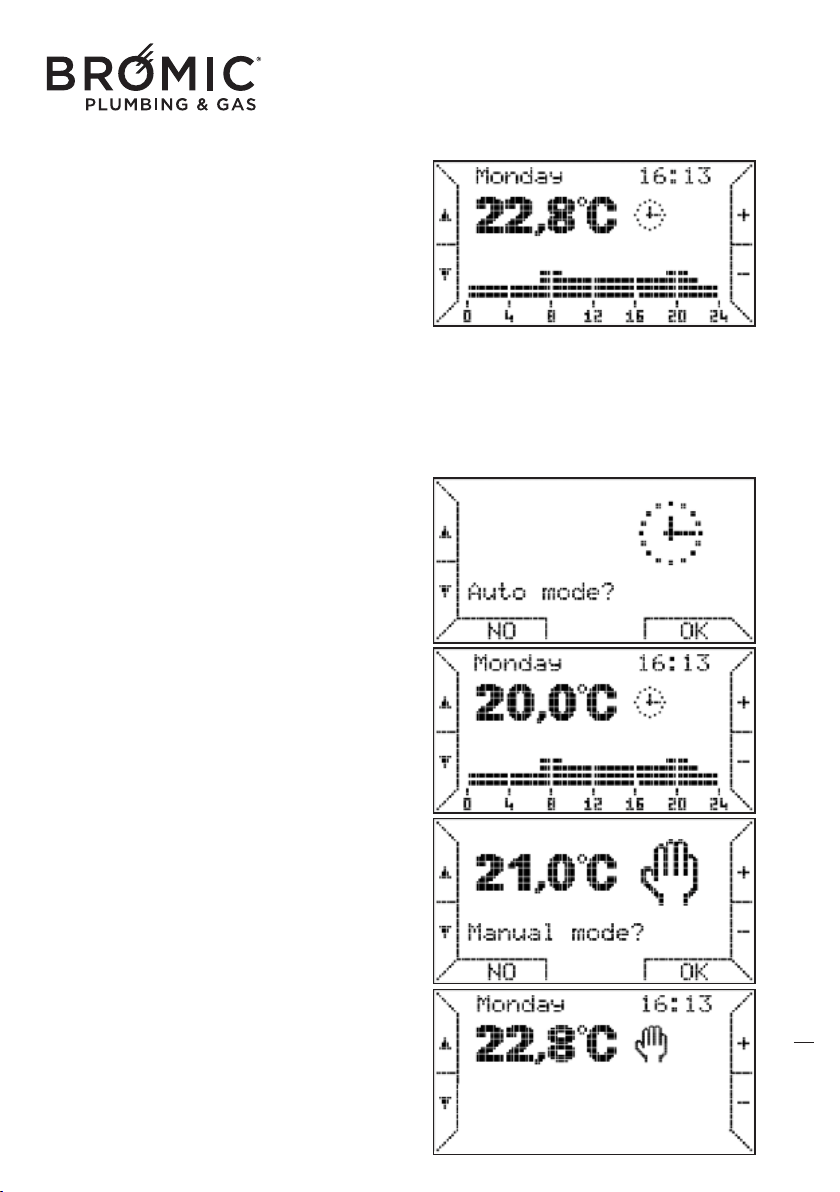
• basic functions
Having set the language, date and time, a screen
appears that shows:
- on top, the current day and time
- below, the ambient temperature (measured every
minute)
- on the right, the operating mode icon (e.g.
Automatic)
- on the bottom, the operating periods of the device.
The 24 hours are divided into intervals of 15 minu-
tes for 4 programmable temperature levels (T0, T1,
T2 and T3).
Beside
the operating icon, a flame switches on to
signal ignition of the burner: 4 types of flames from
small to big, according to the power requested.
• operating mode
AUTOMATIC: the chronothermostat executes the
thermo-regulation program set for the current day.
On the bottom of the display the switch on and off
programmed periods are displayed.
- press key 2 to choose this function and key 6 OK
to enter.
- pres
s keys 8 or 9 to change the four programma-
ble levels (T0, T1, T2 and T3).
- press keys 1 or 2 to move on the desired line (T0,
T1, T2 and T3) and key 6 OK to confirm.
MANUAL: ambient thermo-regulation according to
a temperature selected by the user (thermostat
function).
- press key 2 to choose this function and key 6 OK
to enter.
- press keys 8 or 9 to set the desired temperature.
- press key 6 OK to con
firm and exit.
Wireless Controller - Instruction Manual
14
15
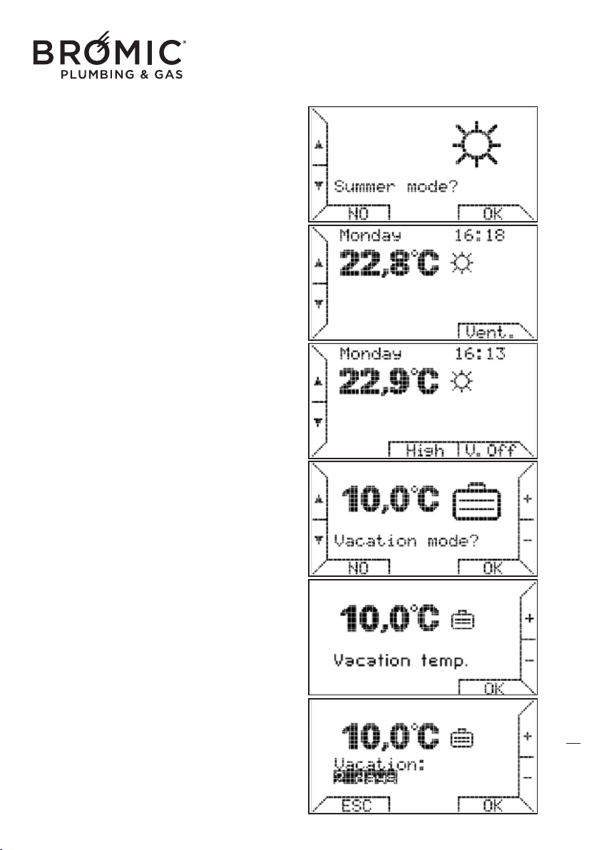
SUMMER: ambient heating function disabled.
Summer ventilation manually enabled.
- press key 2 to choose this function.
- press key 6 to choose VENT.
- press key 5 to choose high speed (HIGH) or low
speed (LOW).
HOLIDAYS: thermo-regulation, enabling the desi-
red temperature to be maintained for a number of
days set by the user (thermostat function).
- press key 2 to choose this function and key 6 OK
to ente
r.
- press keys 8 or 9 to set the desired temperature.
- press key 6 OK to confirm.
- press keys 8 or 9 to set the number of desired
days (max. 99 days).
- press key 6 OK to confirm.
If you press ESC or OK without setting the number
of days, the "HOLIDAY" mode does not activate
and the chronothermostat returns to the previous
mode.
When the period set is up, when the counter
returns to zero, the chronothermo
sat passes to
"automatic" mode and follows the already set
weekly program.
Wireless Controller - Instruction Manual
15
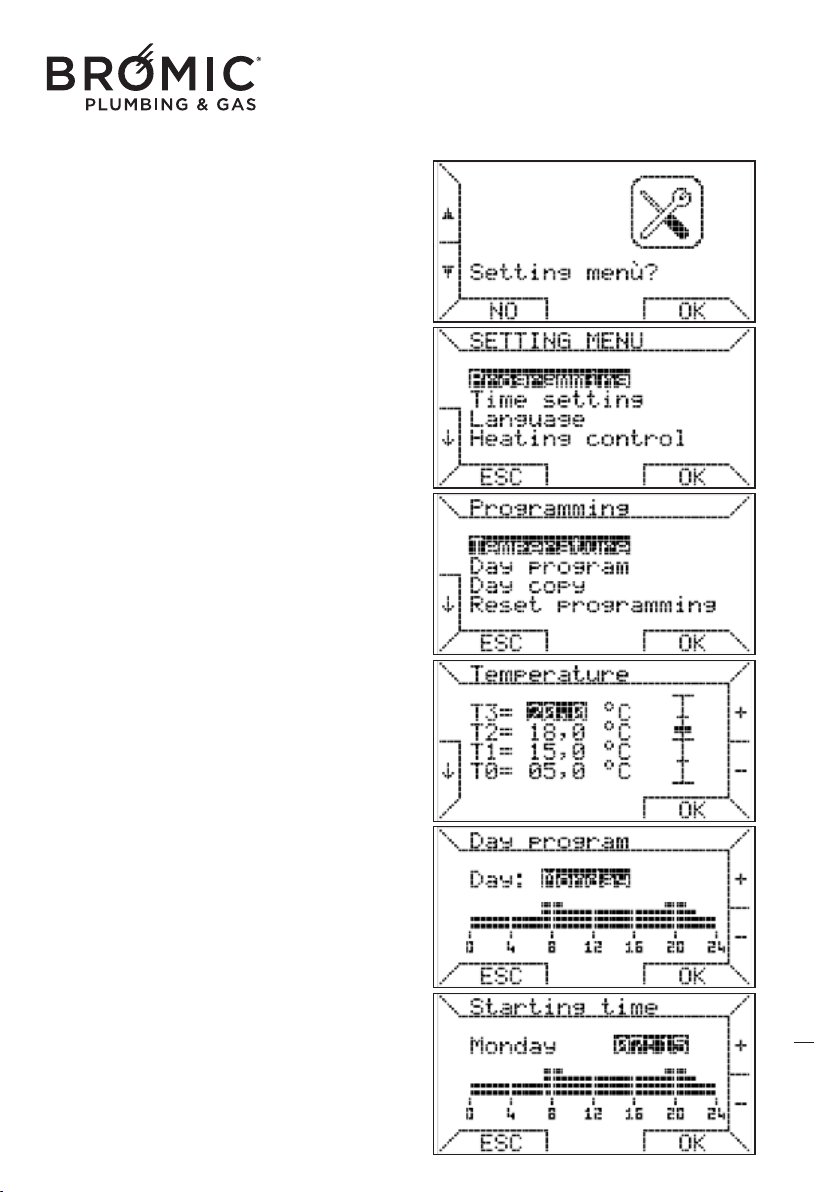
SETTINGS: allows the user to manage the ambient
thermo-regulation, including the weekly program
executed by the chronothermostat as well as confi-
gure the operating parameters.
- press key 2 to choose this function and key 6 OK
to enter.
- press key 6 OK, you enter PROGRAMMING
(weekly).
- press key 6 OK, you enter TEMPERATURE (setting
T0-T1-T2-T3).
- press keys 1 or 2 to go to the desired line T0-T1-
T2-T3.
- press keys 8 or 9 to set the desired temperature
(MIN 1°C and MAX 30°C).
The programming logic combines the MIN tempe-
rature with T0 and the MAX with T3.
The chronothermostat complies with the following
constraint: “T0 ≤ T1 ≤ T2 ≤ T3” and automatically
redimensions all the temperatures input by the user.
- press key 6 OK to confirm and return to the PRO-
GRAMMING menu.
- press keys 1 or 2, choose DAY PR
OGRAMMING
and press key 6 OK.
- press keys 8 or 9 to choose the desired day and
press key 6 OK.
- press keys 8 or 9 to set the start time (intervals of
15 minutes) and press key 6 OK.
16
Wireless Controller - Instruction Manual
16
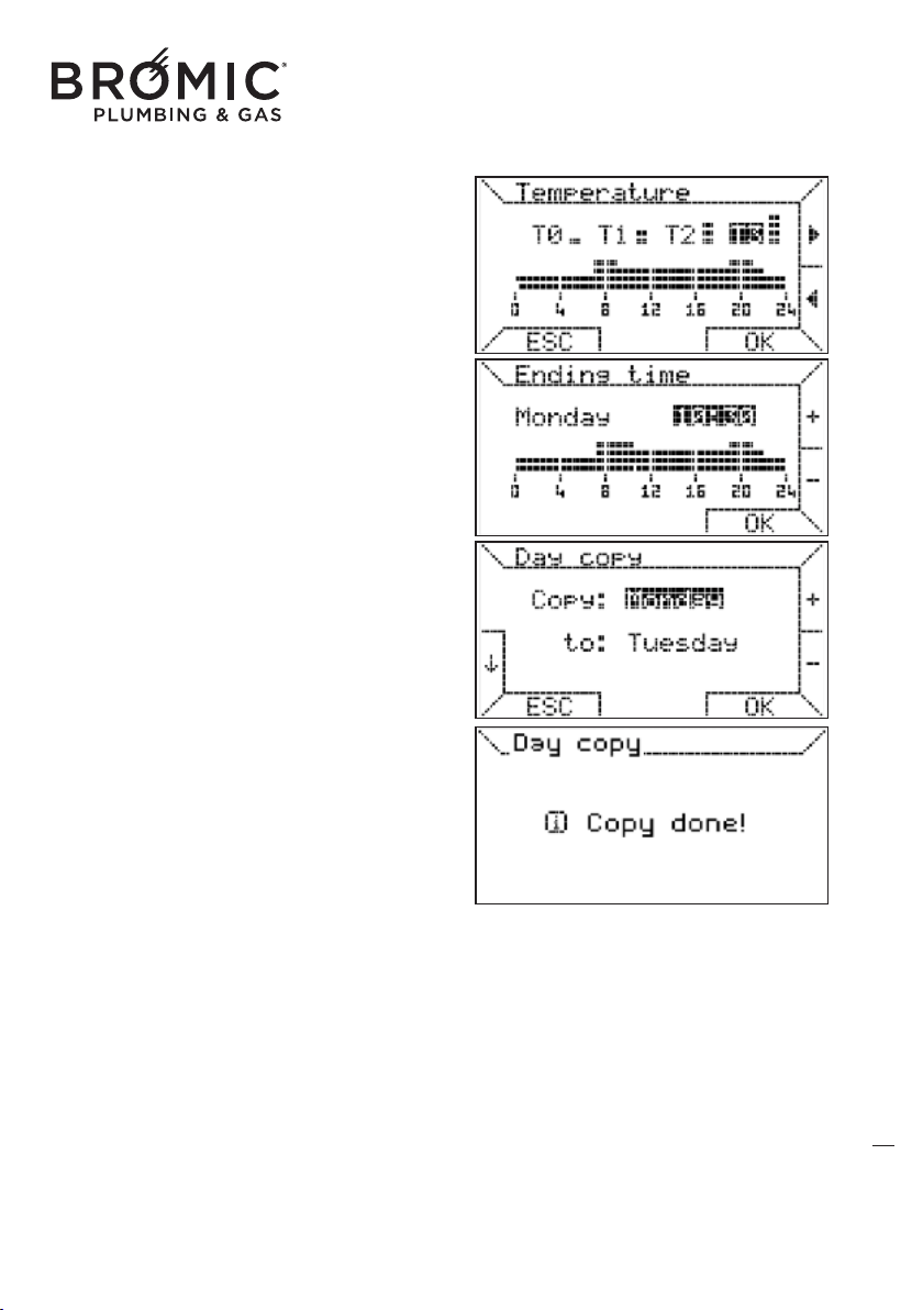
- press keys 8 or 9 to choose the temperature
range (T0-T1-T2-T3) and press key 6 OK to assign
it to the just set time.
- press keys 8 or 9 to set the end time (intervals of
15 minutes) and press key 6 OK.
The start and end times must always differ with the
end time after the start time.
This function allows copying of the program for a
day onto another or on all days.
- press keys 1 or 2 to select COPY DA
Y and press
key 6 OK.
- press keys 8 or 9 to choose the source day to
copy (Monday) and press key 6 OK.
- press keys 8 or 9 to choose the destination day
(Tuesday) and press key 6 OK.
- to confirm the operation was successful, the fol-
lowing message appears: Copied!
17
Wireless Controller - Instruction Manual
17
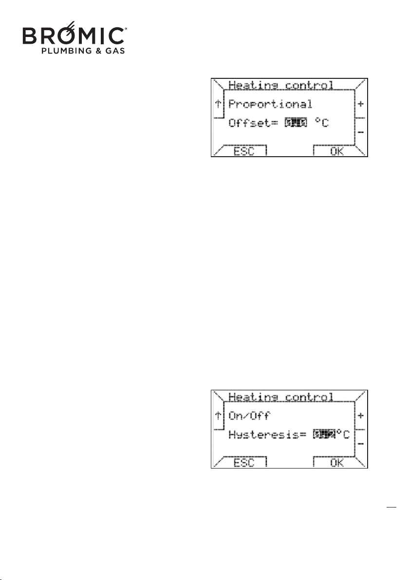
PROPORTIONAL: thermo-regulation method that
regulates the system power percentage based on
the difference in the desired and measured
ambient temperature.
The power percentage, in this case, will be propor-
tional to the difference in these two temperatures
according to the following rule
if Ta ≤ Tap - 2 + offset then P = 100%
if Tap – 2 + offset < Ta < Tap
then Ti = (max / 2) x (Tap – Ta + offset)
i
f Ta ≥ Tap then P = 0%
request made again if Ta ≤ Tap – 0.5
legend:
P = power percentage that varies from 0% to 100%,
Ti = heating set-point,
Tap = programmed ambient temperature,
Ta = measured ambient temperature,
offset = correct value (settable),
The role of the offset (settable from 0 to 1°C) is "to
move" the band so that corresponding to Ta = Tap
a higher power percentage can be obtained
without w
orking on the Tap.
Given the offset default value=0, the band has a
range of 2ºC and is centred in Tap-1.
ON/OFF: similar method to that used by the chro-
nothermostats with clean contact.
Having defined the hysteresis value, settable
between 0 and 1°C (default 0°C), thermo-regula-
tion takes place according to the following rule:
if Ta ≤ Tap - hysteresis then P = 100%
if Ta ≥ Tap + hysteresis then P
= 0 %
legend:
Ti = heating set-point,
Tap = programmed ambient temperature,
Ta = measured ambient temperature,
offset = correct value (settable),
P = maximum value that the heating set-point can
have (set by user).
18
Wireless Controller - Instruction Manual
18
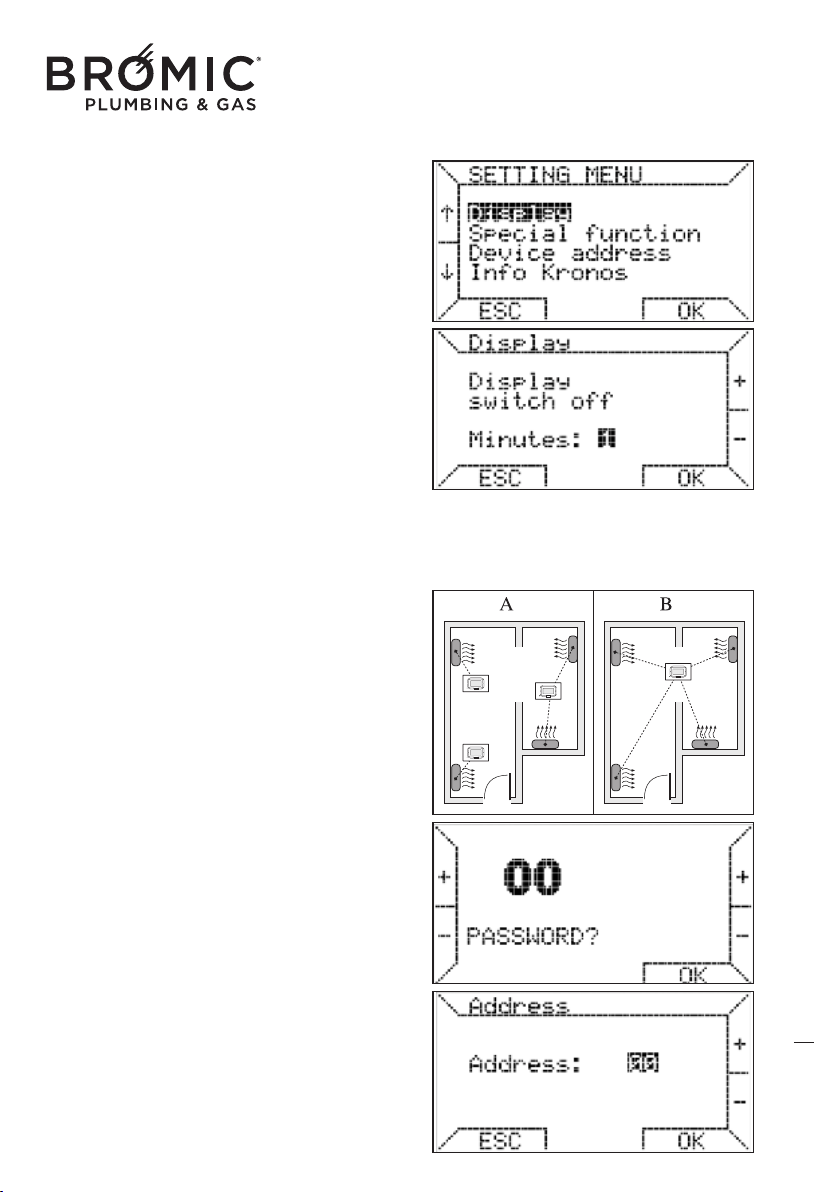
Display: this function allows you to set the time in
which the display remains on before returning to
the low consumption status. You can keep the
display always on to the detriment of the duration
of the batteries.
- press keys 1 or 2 to select Display.
- press keys 8 or 9 to choose the time value or
NEVER (always on).
- press key 6 OK to confirm.
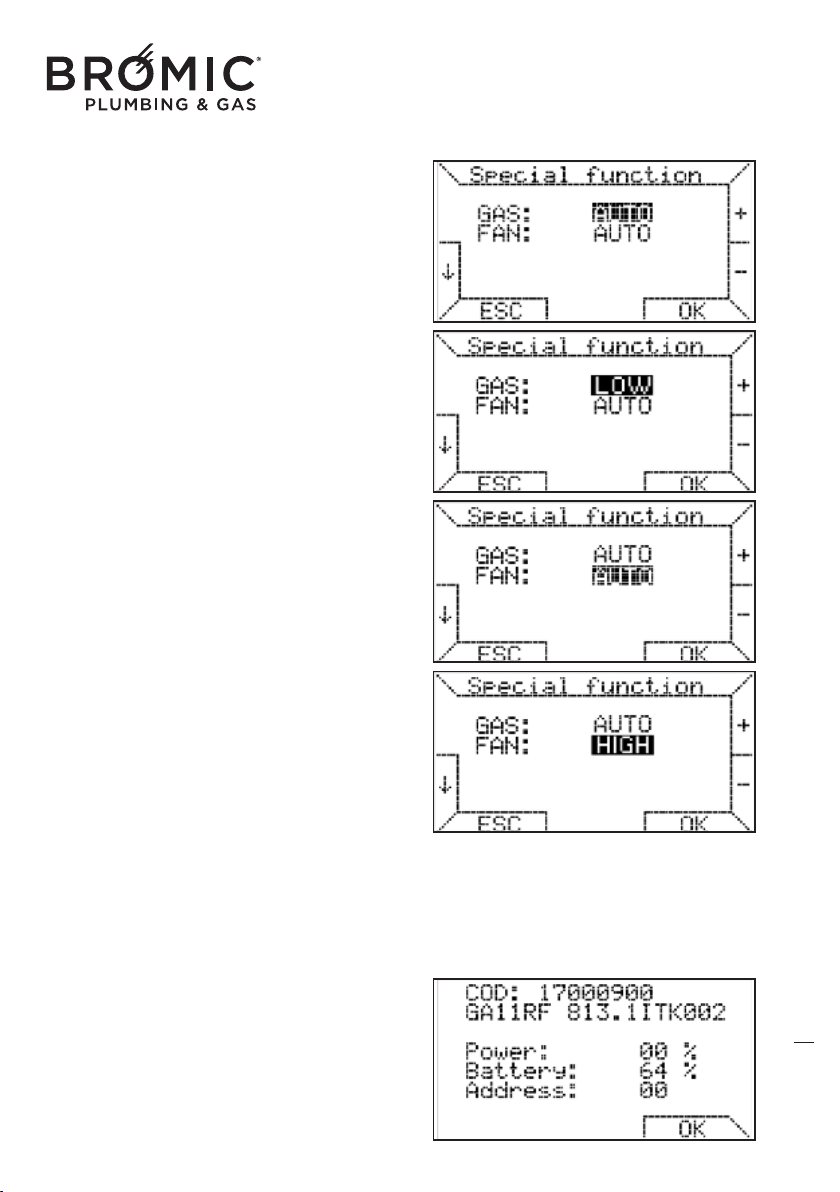
SPECIAL FUNCTIONS
• combine the command with one or more de
vices.
This chronothermostat can be combined with one
or more devices installed in the same environment
or in adjacent ambients (case A or B).
- press keys 1 or 2 to select MENU SETTINGS and
press key 6 OK.
- press keys 1 or 2 to select ADDRESS MODULE
and press key 6 OK.
- the PASSWORD 00 appears, enter number 195
and press key 6 OK.
The password is 195 and cannot be changed.
To set 195, press keys 1 and 2 t
o enter the tenths
and keys 8 and 9 for the units.
- press keys 8 or 9 to select the ADDRESS number
desired (between 00 and 99) and press key 6 OK.
Example: setting number 33, the chronothermostat
will command one or more devices with address 33.
19
Wireless Controller - Instruction Manual
19
• power always on MIN
With the function on, the device always works with
MINIMUM power.
- press keys 1 or 2 to select MENU SETTINGS and
press key 6 OK.
- press keys 1 or 2 to select SPECIAL FUNCTIONS
and press key 6 OK.
- the PASSWORD 00 appears, enter number 195
and press key 6 OK.
- press keys 1 or 2 to go to GAS line.
- press keys 8 or 9 to choose LOW.
- press key 6 OK.
• fan speed always on MAX
With this fu
nction active, the speed of the fan is
always on MAXIMUM.
- press keys 1 or 2 to select MENU SETTINGS and
press key 6 OK.
- press keys 1 or 2 to select SPECIAL FUNCTIONS
and press key 6 OK.
- the PASSWORD 00 appears, enter number 195
and press key 6 OK.
- press keys 1 or 2 to go to the FAN line.
- press keys 8 or 9 to choose HIGH.
- press key 6 OK.
• information on chronothermostat
INFO KRONOS, this function l
ists some of the set-
tings of the chronothermostat: product code,
software version, power percentage, battery loa-
ding percentage (66) and address set (03).
- press keys 1 or 2 to select the MENU SETTINGS
and press key 6 OK.
- press keys 1 or 2 to select the INFO KRONOS
and press key 6 OK to exit.
20
Wireless Controller - Instruction Manual
20
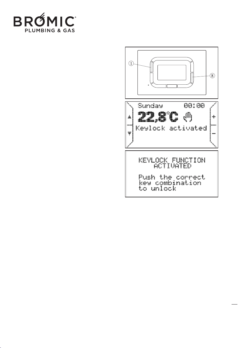
• keypad lock
This function blocks use of all the keys by avoiding
accidental changing of the parameters already set.
- simultaneously press keys 1 and 8 to activate the
keypad lock, the writing "keypads locked"
appears.
- pressing one or more keys the KEYS LOCK
FUNCTION ON screen appears.
- press keys 1 or 8 simultaneously to unlock the
keypad
21
SAVING DATA IN THE CHRONOTHERMOSTAT MEMORY
The chronothermostat saves certain data in the memory so they don't have to be reset when the bat-
teries are replaced. The following are saved: the weekly program and the 4 temperatures
(T0,T1,T2,T3) if changed for the automatic operating mode, the address of the radiofrequency and
the special functions value.
To recharge the weekly program and the 4 default
temperatures (T0,T1,T2,T3):
- press keys 1 or 2 to select the MENU SETTINGS and press key 6 OK.
- press keys 1 or 2 to select PROGRAMMING and press key 6 OK.
- press keys 1 or 2 to select PROGRAM RESET and press key 6 OK.
ATTENTION: press the reset key (3), the weekly program, the 4 temperatures (T0,T1,T2,T3), the
address assigned and the value of the special functions are not reset.
WARNINGS FOR INSTAL
LATION
Always comply with the electrical safety standards in the country of intended installation.
Before operation, check the two alkaline batteries (type AAA LR03 1,5V) are correctly placed,
respecting polarity.
Avoid exposing the system to dripping water.
Wireless Controller - Instruction Manual
21
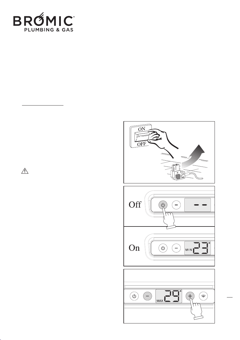
COMMISSIONING
The appliance must be started for the first time by the Technical Assistance Centre authorised by the
Manufacturer, after which it can operate in the mode preferred by the user, manual or automatic.
It may however be necessary to start up the appliance independently, without involving the
Assistance Centre; for example, after a period of absence or prolonged stoppage. In these cases,
perf
orm the following inspections and operations:
WINTER OPERATION
- Open the gas tap.
- Operate the master switch of the power mains or
connect the power plug to the appliance.
- Press the On/Off key to start the appliance, the
display automatically illuminates.
- Press the "+" or "-" to set the desired temperatu-
re, after about 3 seconds the display goes off
automatically.
Turning on or off the display NOT determi-
nes the switching on and off of the unit. The unit
is o
n or off just by pressing the On / Off.
22
Wireless Controller - Instruction Manual
22
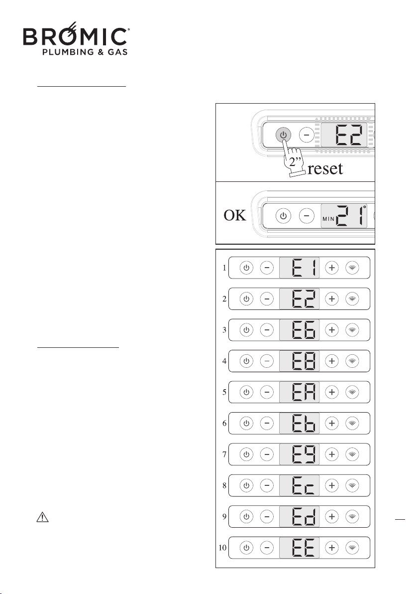
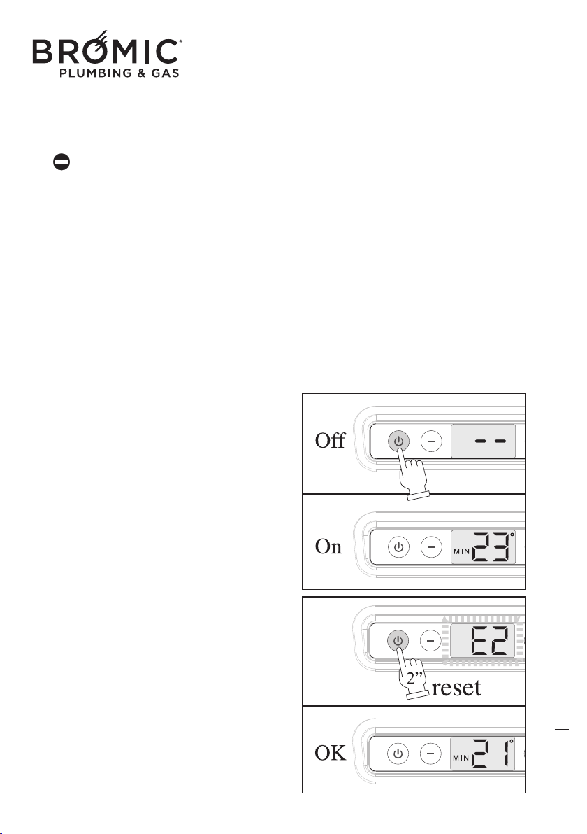
OPERATING ANOMALIES
If the device switches off during normal operation
or does not switch on, pressing the On/Off key,
the error code (E1, E2, E6, etc.) appears on the
display, in this case:
- Check opening of the gas tap.
- Check the electrical power supply is present.
- Take note of the ERROR CODE on the display to
understand the type of anomaly.
- Open the device again.
- Reset the device, keeping the On/Off button
pressed
for 2”.
If, despite various attempts, the device stays in
"BLOCK" mode, contact the Authorised Technical
Support Centre.
Under no circumstances should you fear for
domestic safety, since the device is in the
"BLOCK" position. Disable the gas supply to the
burner, preventing any type of danger. It is a
good idea to completely switch off the device as
specified in the point "DEVICE SWITCH OFF".
DISPLAY ERROR
CODES
When the device is not working, the display fla-
shes to communicate the error code, which would
allow you to identify the type of fault:
- E1, Anomalies on SAS probe
- E2, block because the burner does not switch on
- E6, block due to opening of the air pressure swit-
ch PS during operation
- E8, non-switching of the air pressure switch PS
on start-up
- EA, sticking of the air pressure switch PS on
start-u
p
- EB, communication error with safety device
- E9 - EC - ED - EE, internal safety device faults
The display with the ERROR CODE continues
to flash until the device is reset by pressing the
On/Off key.
23
Wireless Controller - Instruction Manual
23
SWITCHING OFF THE APPLIANCE
The appliance can be turned off in “standby” posi-
tion by means of the On/Off button. In this case,
the set program remains stored in the memory.
For GENERAL SWITCH-OFF use the master switch
on the power supply or disconnect the power plug.
The appliance will switch off completely.
GENERAL switch-off of the appliance must
only be done when the convection fan is no lon-
ger working after a period of heati
ng operation!
SWITCHING OFF FOR LONG PERIODS
If the appliance is not used for a long period of
time, the following operations should be performed:
- Press the On/Off key on board the machine
to switch off the appliance.
- Move the omnipolar master switch, if fitted to
the system, to “off” or remove the plug from the
socket on the appliance;
- Close the gas tap.
CLEANING THE APPLIANCE
Preliminary operations
-
Press the On/Off key on board the machine to switch off the appliance;
- Move the omnipolar master switch, if fitted to the system, to “off” or remove the plug from the
socket on the appliance;
- Close the gas tap;
- Wait for the appliance to completely cool down.
Cleaning the outer surfaces
Clean the accessible parts to remove any dust deposits, spider webs and the like.
Use compressed air to blow away
the dust, including at hard-to-access points.
To clean the plastic or painted parts, never use solvents or abrasive detergents as these could dama-
ge the treated parts.
Use neutral products readily available on the market.
Do not grease the synthetic material parts.
24
Wireless Controller - Instruction Manual
24
To clean the casing, use a soft cloth soaked in neutral-base home-cleaning products, etc. (Car sham-
poo, etc.).
Do not pour liquid directly onto the casing or onto other parts of the appliance, as this could
cause serious damage.
MAINTENANCE
Please remember that PERIODICAL MAINTENANCE – at least once a year – is essential for the safe-
ty, efficiency and long working life of the appliance. It will also
result in lower consumption and less
polluting emissions.
Maintenance can be periodically performed by the Authorised Technical Assistance Centre, which
has all the technical know-how required and, if necessary, original spare parts.
TROUBLESHOOTING
• No power supply
If the appliance fails to start after pressing the
On/Off key on the control:
- Make sure the appliance plug is properly insert-
ed in the p
ower socket.
- Make sure the master switch, if fitted, is in “on”
position.
If the appliance still fails to start, call the
Authorised Technical Assistance Centre.
• BLOCK stop and failed ignition
(see ERROR CODE)
- Make sure the fuel tap is open.
- Restore ignition conditions. Press the On/Off key
for 2 seconds to turn the appliance off and back
on and wait for all ignition phases to be per-
formed again.
Th
is operation can be repeated 3 times at most
and, in the event of its not being successful, posi-
tion the master switch, where provided, on “off”
and contact the Authorised Technical Assistance
Centre.
25
Wireless Controller - Instruction Manual
25
26
• No communication between Wireless and
appliance
- Make sure the Wireless and power batteries are
working properly.
- Check the distance between the Wireless and the
appliance (MAX 10m).
- Make sure the electronic board on the appliance
is working properly.
If communication between the device and thermo-
stat remote stops for more than 5 minutes (ex.
Batteries), the unit goes into standby mode wait-
ing for
a new wireless signal. The unit is not dis-
connected from ever programmable thermostat
remote until the user decides to do so.

Australia & NZ
10 Phiney Place, Ingleburn NSW 2565
Sydney AUSTRALIA
Tel: 1300 276 642
NZ: 0508 276 642
BROMIC.COM/PLUMBING

