

final page size: 8.5 x 5.5 in CRAFTSMANfinal page size: 8.5 x 5.5 in CRAFTSMAN
Edger
Coupe-bordure
Bordeadora
CMEED400
INSTRUCTION MANUAL | GUIDE D’UTILISATION | MANUAL DE INSTRUCTIONES
IF YOU HAVE QUESTIONS OR COMMENTS, CONTACT US.
POUR TOUTE QUESTION OU TOUT COMMENTAIRE, NOUS CONTACTER.
SI TIENE DUDAS O COMENTARIOS, CONTÁCTENOS.
1–888–331–4569 WWW.CRAFTSMAN.COM

English 1
Français 9
Español 18

1
English (original instructions)
This instruction manual uses the following safety alert symbols and words to alert you to hazardous situations and your risk
of personal injury or propertydamage.
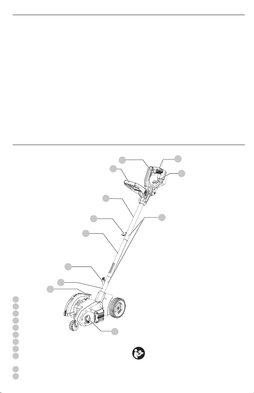
Mounting hole
Knob
Upper tube
Middle tube
Lower tube
Auxilliary handle
Trigger switch
Main handle
Cut depthknob
Edge guide lever
Extension cord retainer
Fig. A

2
Fig. B

3
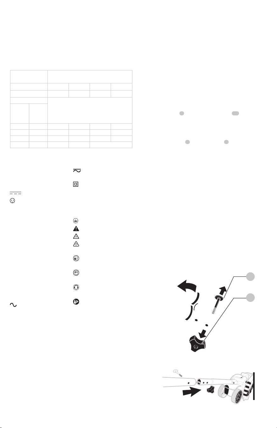
To reduce the risk of electric shock, this equipment has
a polarized plug (one blade is wider than the other). This
equipment must be used with a suitable polarized 2 wire or
3 wire extension cord. Polarized connections will fit together
only one way. Make sure that the receptacle end of the
extension cord has large and small blade slot widths. If the
plug does not fit fully into the extension cord, reverse the
plug. If it still does not fit, obtain a suitable extension cord. If
the extension cord does not fit fully into the outlet, contact
a qualified electrician to install the proper outlet. Do not
modify the appliance plug or extension cord in anyway.
4
This edger is intended for householduse.
use under wet conditions or in presence of
flammable liquids orgases.
let children come into contact with the tool.
Supervision is required when inexperienced operators use
thistool.
1. Remove knobs and curved head bolts from
handle tube mountingholes.
2. Remove tape which secures internal jacketed cable
totubes.
3. Slide middle tube
into upper tube and fasten
handle tubes together with the knob and curved head
bolt. Note that when you first insert the bolt it may
be necessary to wiggle it carefully to get it past the
jacketed cable inside the tube. There are two positions
available for adjustment to your preferred height
setting. See Figure G for upper handle orientation.
Ensure the cable moves smoothly into the handle tubes
whileassembling.
4. Push jacketed cable down into lower tube to remove
the slack. Slide the middle tube into the lower by
locating the groove and the bump. Fasten handle tubes
together with the remaining knob and curved head
bolt. Note that when you first insert the bolt it may
be necessary to wiggle it carefully to get it past the
jacketed wire inside thetube.
Be sure your power supply agrees with the nameplate
marking. Voltage decrease of more than 10% will cause loss
of power and overheating. These tools are factory tested; if
this tool does not operate, check power supply.
Fig.C
Fig.D
5
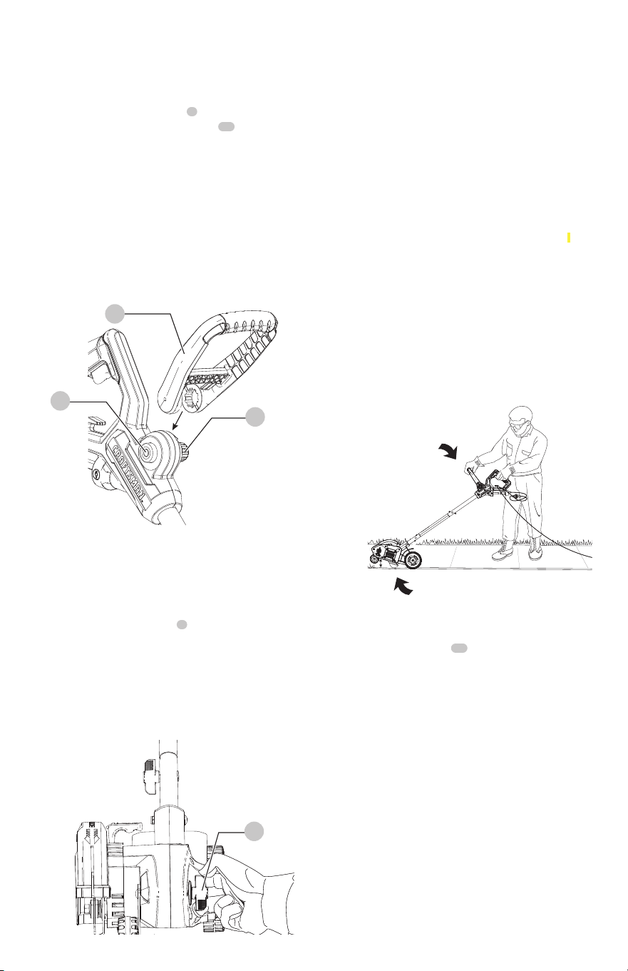
For some models the auxiliary handle may need to be
attached. If the model needs the auxiliary handle attached,
please refer to theseinstructions.
1. To attach the auxiliary handle
, press in on the
auxiliary handle adjustment buttons on both sides
of the upper housing as shown in Figure E
2. Position the auxiliary handle as shown in Figure E .
Partially push the auxiliary handle on so it will hold the
buttons in when you release them with your hand.
3. Push the auxiliary handle completely onto the housing
and position it slightly until it “snaps” intoplace.
To adjust the auxiliary handle up or down, press in on
the buttons and raise or lower the handle.
The handle should be adjusted so that your front arm
is straight when the edger is in the workingposition.
Fig.E
The front wheel can be adjusted to allow a deeper or
shallower cut, and to increase the life of the blade.
1. Wait for blade to come to completestop.
2. Unplugtool.
3. Loosen the cut depthknob
.
4. Adjust wheel depth, using the depth indicator (on the
wheel bracket and the marking on the fronthousing.
Recommend 1 " (2.5 cm) depth foredging.
5. Tighten knobfirmly.
Thick overgrowth may drag on the guard. Reduce
cut depth to minimum to help reduce thiseffect.
Fig. F
The edge guide is useful for cutting a straight path along
sidewalks. For landscaping or trenching in the yard the edge
guide can interfere with moving the edger through hard
soil or sod. The edge guide can be adjusted so that the tool
will also perform TRENCHING and LANDSCAPINGoperations.
Pull edge guide lever sideways to unlock from the guard
tab in direction of small arrow. Lift the lever up until the
lower square notch in the lever lines up with the tab on
the guard. In this position the edge guide is lifted up so the
tool can easily cut along the edges of flower and shrubbery
beds, and around trees in preparation for trenching or
sodremoval.
To return edge guide to lower position, pull lever sideways
and push down until guard tab fits into upper leverhole.
You may need to tilt edger back to allow edge guide
to be moved into trenchingposition.
Fig.G
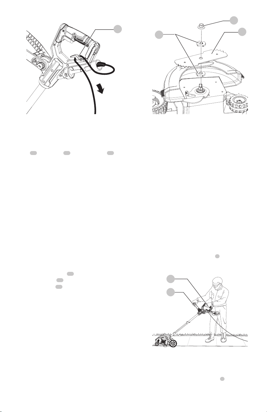
An extension cord retainer is built into the switch
handle to reduce strain on the power cord. To use this
feature, simply double the extension cord as shown, about
1' (30 cm) from the end, and insert it into the end of the
handle. Hook the loop formed by doubling the cord over
the tab. Gently tug on the cord to ensure that it is firmly
retained in thehandle.
Keep extension cord clear of operator, unit, and any
obstacles at all times. Do not expose the cord to heat, oil,
water, or sharpedges.
6
Fig.H
The blade
, two spacers and hex head nut with
conical washer should be attached to your edger in the
order shown. Please check that the blade has been properly
mounted before using your edger. The edger blade has two
wear indicators that show when blade needs to be replaced.
When the blade wears to the small hole at each end of the
blade it will give only 1/4 " (6 mm) depth of cut and should
bereplaced.
To increase blade life, keep initial cutting depth at
minimum and increase depth setting as bladewears.
1. Loosen the hex head nut
(9/16 "). Use a 1 " wrench
on the outer spacer , or a 2 " x 4 " wood block
between the blade
and guard if necessary to hold
the blade fromturning.
2. Ensure inner spacer is on shaft—”flats” in spacer hole
must engage with “flats” onshaft.
3. Holding the spacer in place, put the blade on the shaft,
as shown (FigureI).
4. Hold the blade against the spacer and install the outer
spacer, again aligning the flats in the spacer with the
flats on theshaft.
5. Install the hex head nut and conical washer, then
tighten with awrench.
Replace hex head nut and conical washer only
with identical replacementpart.
Proper hand position requires one hand on the main handle
and one hand on the auxilliary handle .
Fig.I
Fig.J
To turn tool ON, squeeze the trigger switch . The trigger
has been designed so that it is very easy to hold in the ON
position. To turn tool OFF, release thetrigger.

7
Remove and clean any debris from the outside of the edger
and inside of guard before storage. Refer to
section. If necessary, the edger may be stored by hanging
on a hook by its handle.
Fertilizers and other garden chemicals contain agents that
greatly accelerate the corrosion of metals. If you use the
tool in areas where fertilizers or chemicals have been used,
the tool should be cleaned immediately afterwards. Wipe
all exposed parts with a damp cloth. You may lubricate only
metal parts with a light petroleum based oil.
When cleaning, DO NOT immerse tool in water or squirt it
with ahose.
The edger is a major appliance and should not be
operated simultaneously with other major appliances on
the same householdcircuit.
1. Set cut depth at 1 " and set edge guide to
the down position, refer to
Instructions.
2. Before starting the edger, line up the tool so the edge
guide rests against the edge of the paved surface.
Both rear wheels should be on the paved surface
whenedging.
When there is heavy overgrowth of grass over the
paved surface it may drag on the guard. An initial cut may
be required with the edger on the grass side. This will
require lifting up the edge guide and may require reducing
the depth of cut (refer to
instructions).
3. To avoid kickback of edger, tilt the handle down so the
blade is above theground.
4. Turn switch ON and allow blade to spin without
movingtool.
5. Slowly lift the handle to lower the blade, finding the
edge of the paved surface and start edging. Then
move tool forward slowly along edge of paved surface,
keeping the edge guide pressed lightly against the
pavementedge.
For the first edging each season, it is best to move
forward slowly because grass is thickest then.
Subsequent edging will be completed more rapidly.
If the tool slows down, back it up an inch or two
until the blade comes up to normal speed. During
edging some sparks may be generated from hitting
stones. This is normal. Do not attempt to edge when
the grass or soil is wet or moist—for electrical safety
and to prevent clogging of the blade chamber. If
you must edge under conditions that cause the
blade chamber to become clogged, release trigger,
wait for blade to come to complete stop. Unplug
tool, open door and remove clogged material with
a stick. To continue to operate the tool in a clogged
condition will seriously overload themotor.

8
Recommended accessories for use with your tool are
available at extra cost from your local dealer or authorized
service center. If you need assistance in locating any
accessory, please contact CRAFTSMAN call 1-888-331-4569.
can return it within 90 days from the date of purchase with a
receipt for a full refund – no questionsasked.
This warranty does not apply to products
sold in Latin America. For products sold in Latin America,
see country specific warranty information contained in
the packaging, call the local company or see website for
warrantyinformation.
If your warning
labels become illegible or are missing, call
for a freereplacement.
Thank you for your purchase. Register your product nowfor:
Registering your product will
help you obtain more efficient warranty service in case
there is a problem with yourproduct.
In case of
an insurance loss, such as fire, flood or theft, your
registration of ownership will serve as your proof
ofpurchase.
Registering your product will
allow us to contact you in the unlikely event a safety
notification is required under the Federal Consumer
SafetyAct.
• Register online at
CRAFTSMAN will repair or replace, without charge, any
defects due to faulty materials or workmanship for three
years from the date of purchase. This warranty does not
cover part failure due to normal wear or tool abuse. For
further detail of warranty coverage and warranty repair
information, visit or call
. This warranty does not apply to
accessories or damage caused where repairs have been
made or attempted by others. THIS LIMITED WARRANTY
IS GIVEN IN LIEU OF ALL OTHERS, INCLUDING THE IMPLIED
WARRANTY OF MERCHANTABILITY AND FITNESS FOR A
PARTICULAR PURPOSE, AND EXCLUDES ALL INCIDENTAL
OR CONSEQUENTIAL DAMAGES. Some states do not allow
limitations on how long an implied warranty lasts or the
exclusion or limitation of incidental or consequential
damages, so these limitations may not apply to you. This
warranty gives you specific legal rights and you may have
other rights which vary in certain states orprovinces.
If you are not completely satisfied with the performance of
your CRAFTSMAN Power Tool or Nailer for any reason, you
9
Ces guides d'utilisation utilisent les symboles et termes d'alarmes sécurité suivants pour vous prévenir de situations
dangereuses et de risques de dommages corporels ou matériels.
Français (traduction de la notice d’instructions originale)
Trou de montage
Bouton
Tube supérieur
Tube central
Tube inférieur
Poignée auxiliaire
Gâchette
Poignée principale
Bouton de profondeur
de la coupe
Levier du guide de bord
Enrouleur de la rallonge
Fig. A

10
Fig. B

11
Le produit est muni d’une fiche polarisée (une lame plus
large que l’autre) afin de minimiser les risques de secousses
électriques. Le produit doit alors être utilisé avec un cordon
de rallonge bifilaire ou trifilaire approprié. Ce genre de fiche
n’entre que d’une façon dans une prise polarisée. S’assurer
que la douille de la rallonge possède une fente plus large
que l’autre. Lorsqu’on ne peut insérer la fiche à fond dans la
rallonge, il faut tenter de le faire après avoir inversé les lames
de côté. Si la fiche n’entre toujours pas dans la rallonge, il
faut se procurer une rallonge appropriée. Lorsqu’on ne peut
insérer la fiche de la rallonge à fond dans la prise, il faut
communiquer avec un électricien certifié pour qu’il installe
une prise appropriée. Il ne faut pas modifier la fiche de l’outil
ni larallonge.

12
1. Retirer les boutons et les boulons à tête bombée
des trous de montage du tube de lapoignée.
2. Retirer le ruban qui fixe solidement le câble gainé
interne auxtubes.
S’assurer que le bloc d’alimentation est compatible avec
l’inscription de la plaque signalétique.Une diminution de
tension de plus de 10 % provoquera une perte de puissance
et une surchauffe. Ces outils sont testés en usine; si cet outil
ne fonctionne pas, vérifier l’alimentation électrique.
Ce coupe-bordure est conçu pour un usagedomestique.
les utiliser en milieu ambiant humide ou en
présence de liquides ou de gazinflammables.
le laisser à la portée des enfants. Une supervision
est nécessaire auprès de tout utilisateur nonexpérimenté.