Loading ...
Loading ...
Loading ...
8 49-6000061
Installation Instructions
INSTALLATION INSTRUCTIONS
MOUNTING SYSTEM INSTALLATION
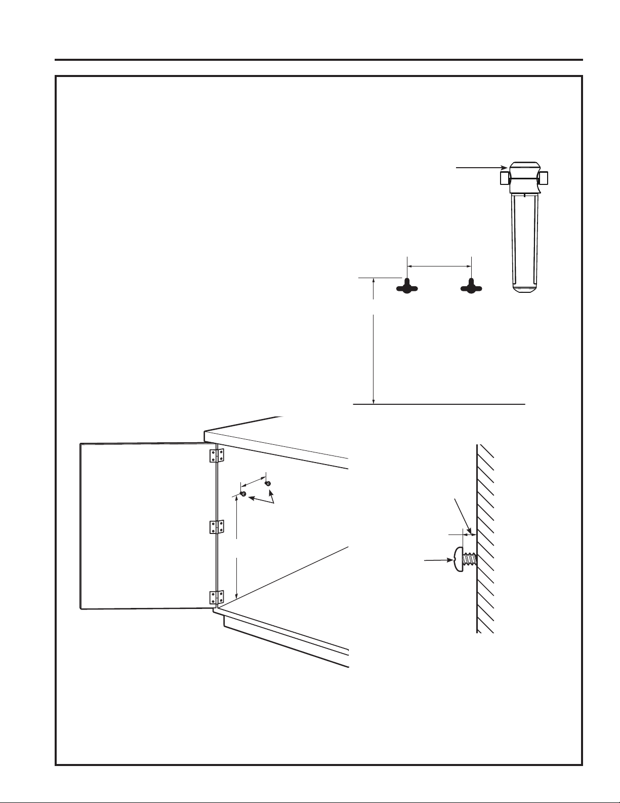
Pick a location under the sink to mount the system. Location should be easily accessible, with 4” of
clearance between the bottom of the filter canisters and the floor or bottom of the cabinet; any less
will result in difficulty of removing filter canisters (see Fig. 5). Allow enough space on either side of the
system for the tubing connections. System should be mounted at least 7” from front of cabinet to allow
proper routing of tubing.
SCREW INSTALLATION
1. Remove the top cover of system.
2. Screws should be placed a minimum of 15 inches above the bottom of the
cabinet or floor where the system is to be mounted (Fig. 5).
NOTE: Any distance lower may result in filter canisters interfering
with the floor when removed.
3. Use the system as a template to mark screw hole locations
where the screws are to be installed. Install screws into the
wall, leaving 3/16 inch clearance between the head of the screw
and wall (drill pilot holes if needed) (Fig. 6). Use anchors if
mounting to drywall. Anchors require a 1/4” hole.
4. Hang system on screws and tighten until system is held firmly.
5. Install top cover onto system.
6. Install 4 foot long yellow tube into inlet (left side) of system (inlet
and outlet are labeled on top of the system).
7. Install 4 foot long blue tube into outlet (right side) of system.
Pull firmly on tubes to make sure they are secure.
8. Remove shrink wrap from filters and install in system by turning approximately 1/3 turn until locked into place. Filter
will raise up as it is turned. Filter label will be centered and facing forward when fully installed.
NOTE: System may exhibit low flow or no flow at all if the filter is not fully installed.
9. Turn on water supply valve and check for leaks.
10.
Perform Flush Procedure as described on page 9, steps 3-7.
15 inches
Screws
Screw
3/16 inch
Fig. 6
Fig. 5
Wall
System
Top Cover
15 inches
11/16
inches
Bottom of Cabinet or Floor
Template for screw hole pattern
on back of filtration system
(not to scale)
Loading ...
Loading ...
Loading ...