Loading ...
Loading ...
Loading ...
49-6000061 5
INSTALLATION INSTRUCTIONS
Installation
Kitchen Faucet Filtration System
Instructions
GXK185KBL
WARNING
—
Read “Important Safety
Information” on page 3 before beginning
installation.
TOOLS AND MATERIALS
REQUIRED FOR INSTALLATION
• Phillips screwdriver
• Two (2) adjustable wrenches
• Electric drill and drill bit to drill 1.25” hole (type as
required) if mounting hole is needed for control valve
• Tape measure
•
If your main water line is a rigid pipe, you will require
a compression fitting and possibly other plumbing
hardware to complete the installation (sold separately).
NOTICE —
To avoid damaging the sink or counter
top, consult a qualified plumber or installer for drilling
procedures. Special drill bits may be needed for granite,
stone, porcelain or stainless steel.
CONTENTS INCLUDED
WITH THE PRODUCT
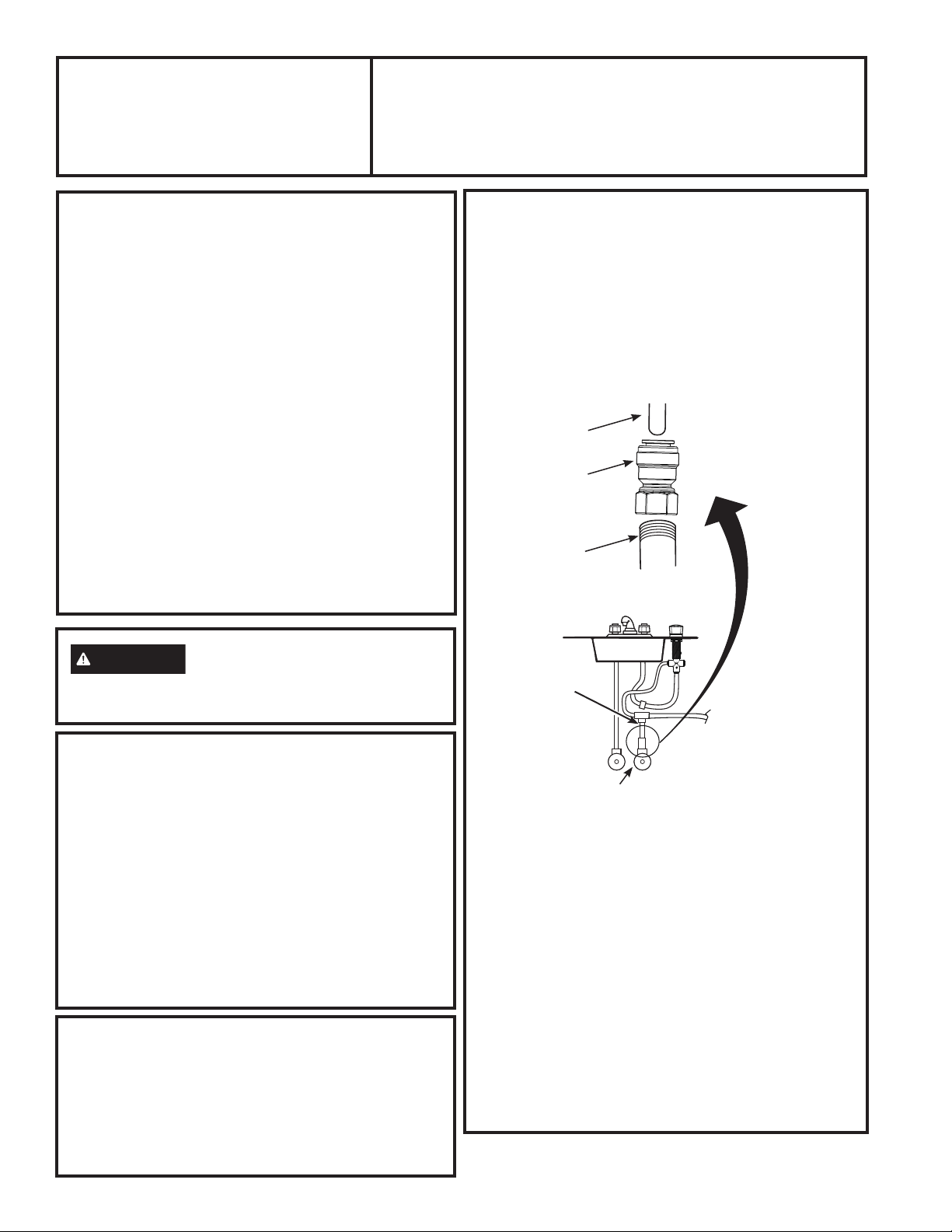
COLD WATER CONNECTION
A typical connection using the included water supply
fitting is shown in the illustration below.
1. Close the water shut-off valve that is immediately
in front of the supply tube and open the faucets to
drain water from the sink cold water pipe.
2. Remove line that connects the cold water from faucet
line to the supply valve. Some water may spill out.
3. Hand tighten the angle stop valve adapter onto
the cold water valve. NOTE: A minimum of
approximately 8 threads is required on valve
stem. Finish tightening 1/2 turn with adjustable
wrench. Be careful not to overtighten or cross-thread
as damage to threads can occur.
Some valve threads may be exposed when adapter is
fully seated.
4. Insert one foot long yellow tube fully into angle stop
valve adapter. Pull firmly on tube to make sure it is
secure.
5. Insert one foot long yellow tube into bottom of T-fitting
(see Figure 1). Insert 3 foot long yellow tube into one
side of T-fitting. Insert 4 foot long yellow tube into
other side of T-fitting. Pull firmly on tubes to make
sure they are secure.
1 foot Yellow
3/8” Tube
Cold Water Shutoff
Fig. 1
Angle Stop
Valve Adapter
Existing Cold
Water Valve
(Approximately 8
threads minimum)
T-Fitting
BEFORE YOU BEGIN
Read these instructions completely and
carefully.
•
IMPORTANT – Save these
instructions for local inspector’s use.
•
IMPORTANT – Check with your
local public works department for plumbing
codes. You must follow their guides as you
install the Water Filtration system.
• Note to Installer – Be sure to leave these
instructions with the Consumer.
• Note to Consumer – Keep these
instructions for future reference.
• Skill level – Installation of this appliance requires
basic mechanical and electrical skills.
• Completion time – 60-90 minutes
• Proper installation is the responsibility of the
installer.
• Product failure due to improper installation is not
covered under the Warranty.
• Water filter system
assembly, including
mounting screws
• Water line adapters
and tubing
• Control Valve with LED
Lights
• Decorative Knob and Nut
• Timer Box
• Batteries
Loading ...
Loading ...
Loading ...