Loading ...
Loading ...
Loading ...
49-6000061 7
Installation Instructions
INSTALLATION INSTRUCTIONS
INSTALL THE CONTROL VALVE
(continued)
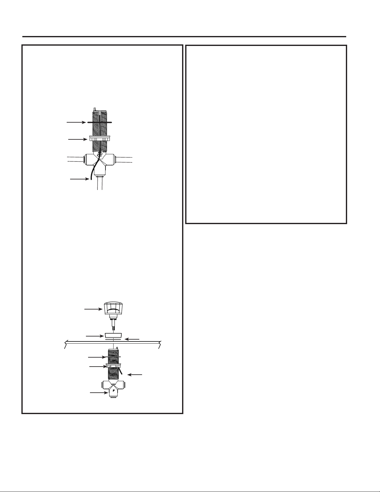
3. With wire routed under rubber gasket and
locking nut (as shown below) thread nut at
least 3/4 toward bottom.
4. With “F” port label facing toward you (wire
groove facing back of cabinet) insert control
valve up through hole in sink/counter top.
5. Install 2nd rubber gasket on the control valve.
Insert decorative nut on top of control valve
turning fully until it stops, approximately two
turns of nut. Do not overtighten.
6. Turn locking nut clockwise to tighten until it is
firmly secure against underside of sink/counter
top. Do not allow control valve body to rotate,
“F” port label should face toward you after
locking nut is tight.
Rubber Gasket
Locking Nut
Wire
INSTALL THE CONTROL VALVE
(continued)
7. Insert control knob into valve body.
NOTE: Knob only inserts in one position,
rotate slowly until you feel it drop slightly
into place. Then push down firmly to snap
in place.
8. Check knob rotation. Knob should rotate 180
degrees and point towards you as it rotates
left/right. If point of knob rotates towards
wall, then unit is installed backwards. Please
review step 2.
9. Connect wire to timer box.
10. Find suitable location for timer box and
battery access. Mount timer box to side of
wall or cabinet with two screws (and drywall
anchor) provided. NOTE: Be careful not to
pinch or screw through the wire.
11.Install two AA, 1.5 volt, batteries into timer box.
Control Knob
Decorative Nut
Wire
Rubber Gasket
Locking Nut
NOTE:
“F” facing toward you.
Rubber Gasket
Loading ...
Loading ...
Loading ...