Loading ...
Loading ...
Loading ...
Removing the Burner Door Assembly
5.
1. Turn off the gas to the water heater at the manual
shut-off valve (Figure 2).
2. Turn the gas control/temperature knob to the "OFF"
position (Figure 22).
3. Remove the outer door.
4. Remove the two screws (1/4" nut driver) securing the
burner door assembly to the combustion chamber
(Figure 24).
Disconnect the pilot tube (7/16" wrench), the igniter wire
from the igniter lead wire, and manifold tube (3/4" wrench)
at the gas control valve/thermostat. Disconnect the sensor
wires (lift white lever outward, then gently pull the plug
downward). Also, use needle nose pliers to disconnect the
red (+) and white (-) thermopite wires from the gas control
valve/thermostat. See Figures 24 & 25.
GAS CONTROL VALVE/
THERMOSTAT
PIEZO IGNITER
PILOT TUBE
VIEWPORT
OUTER DOOR
NOT SHOWN
BURNER DOOR
SCREWS (2) --
TEMPERATURE SENSOR
WIRE CONNECTION
/THERMOPILE
WIRE
CONNECTIONS
SENSOR
DOOR
MANIFOLD COMPONENT BLOCK
FIGURE 24.
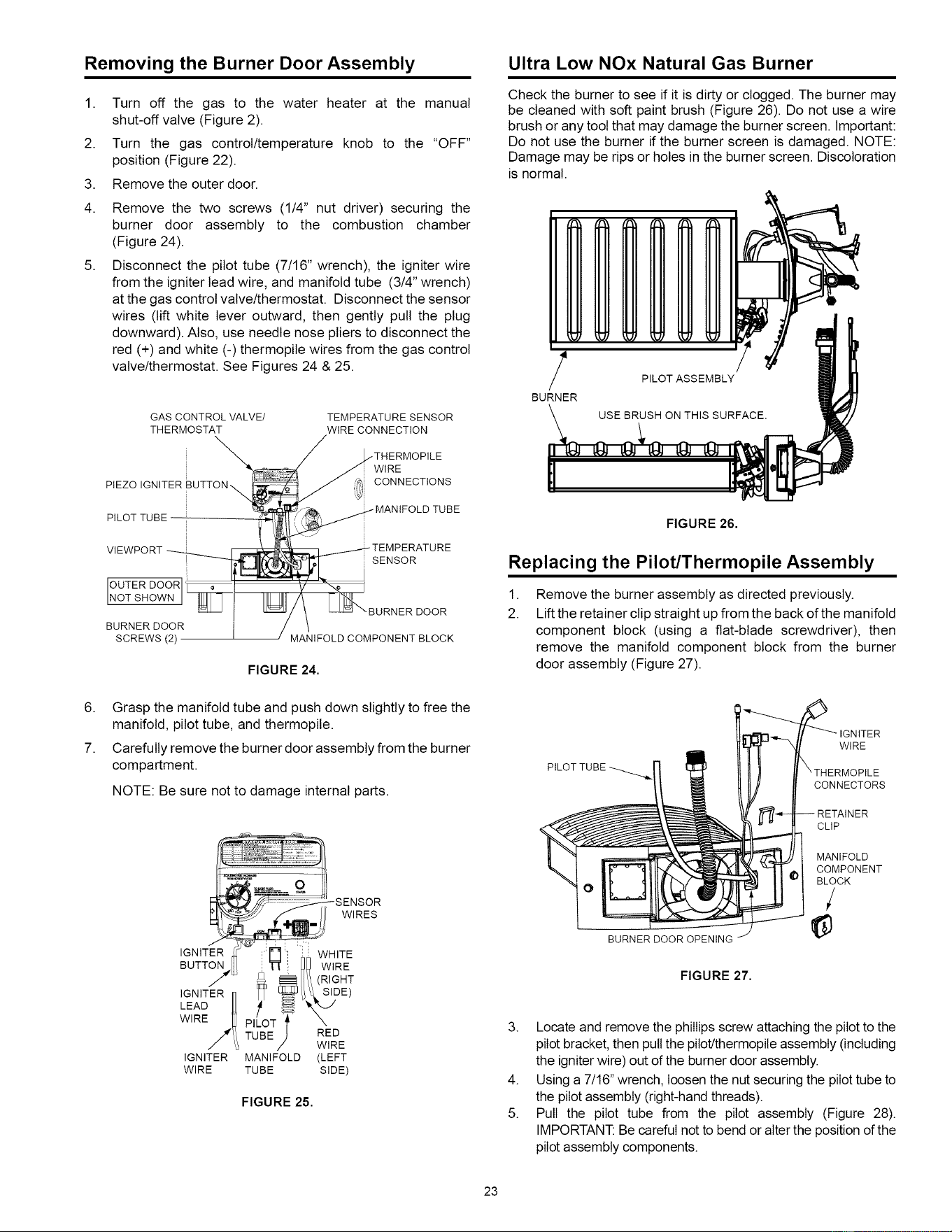
Ultra Low NOx Natural Gas Burner
Check the burner to see if it is dirty or clogged. The burner may
be cleaned with soft paint brush (Figure 26). Do not use a wire
brush or any toot that may damage the burner screen. Important:
Do not use the burner if the burner screen is damaged. NOTE:
Damage may be rips or holes in the burner screen. Discoloration
is normal.
J
BURNER
PILOT ASSEMBLY
USE BRUSH ON THIS SURFACE,
FIGURE 26.
Replacing the Pilot/Thermopile Assembly
1.
2.
Remove the burner assembly as directed previously.
Lift the retainer clip straight up from the back of the manifold
component block (using a fiat-blade screwdriver), then
remove the manifold component block from the burner
door assembly (Figure 27).
6. Grasp the manifold tube and push down slightly to free the
manifold, pilot tube, and thermopite.
7. Carefully remove the burner door assembly from the burner
compartment.
NOTE: Be sure not to damage internal parts.
SENSOR
W,RES
IGNITER _- r ' :: WHITE
BUTTON I! _" [_ WIRE
IGNITER r] _ _/i_ SIDE)
LEAD U[ _ _
WIRE _ PIL'OJ X
/'4/i TUBE RED
/_ WIRE
IGNITER MANIFOLD (LEFT
WIRE TUBE SIDE)
FIGURE 25.
PILOT
IGNITER
WIRE
CONNECTORS
O
BURNER DOOROPENING
FIGURE 27.
CLIP
MANIFOLD
COMPONENT
BLOCK
/
3. Locate and remove the phillips screw attaching the pilot to the
pilot bracket, then pull the pitot!thermopite assembly (including
the igniter wire) out of the burner door assembly.
4. Using a 7/16" wrench, loosen the nut securing the pilot tube to
the pilot assembly (right-hand threads).
5. Pull the pilot tube from the pilot assembly (Figure 28).
IMPORTANT: Be careful not to bend or alter the position of the
pilot assembly components.
23
Loading ...
Loading ...
Loading ...