
Use & Care Guide
Manual de Uso y Cuidado
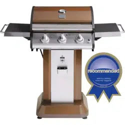
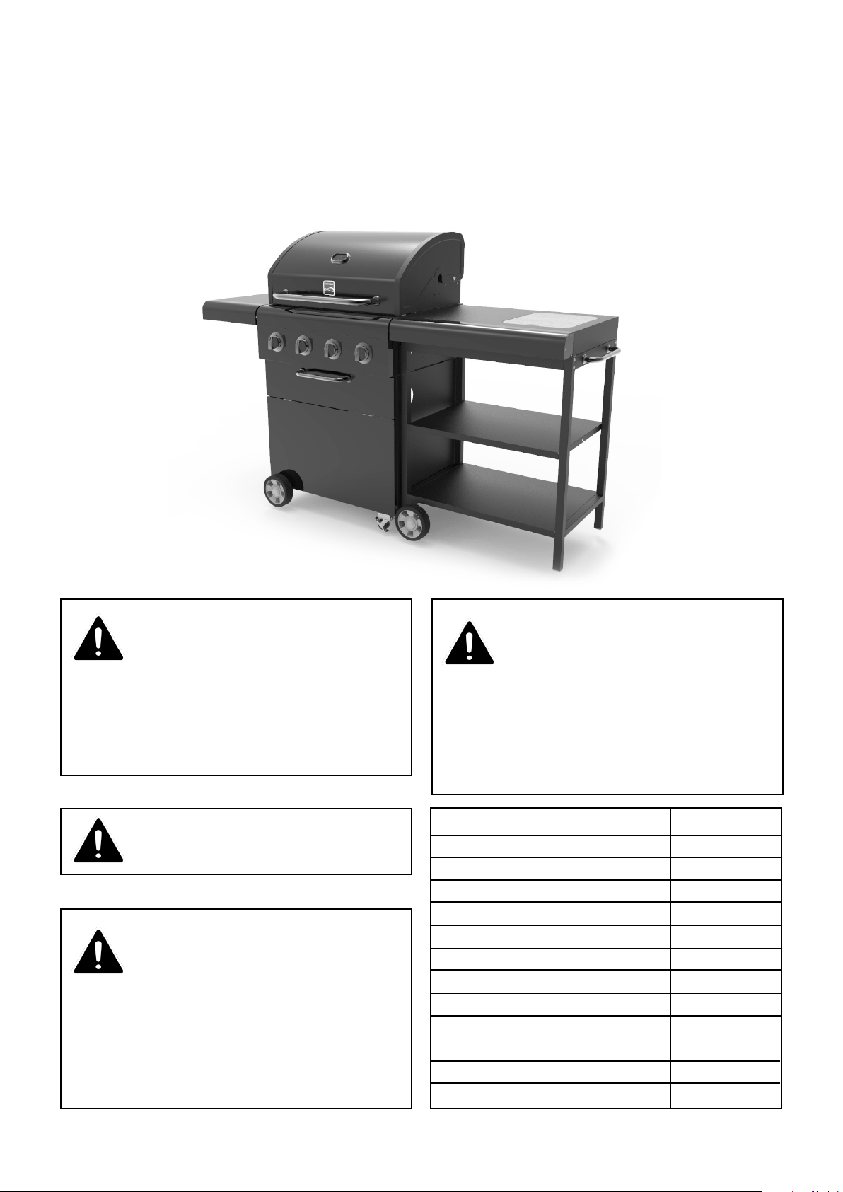
4 Burner LP Gas Grill
with Side Cart
Parrilla a gas LP con 4
quemadores y carro lateral
Model/Modelo: 152.23151910
Sears Brands Management Corporation
Homan Estates, IL 60179 U.S.A.
www.kenmore.com
Kenmore
®
Customer Care Hotline
To schedule in-home repair service
or order replacement parts
Para pedir servicio de reparación
a domicilio, y ordenar piezas
1-844-553-6667
www. kenmore. com
®

These instructions are for your safety. Read them thoroughly before use
and retain them for future reference.
WARNING:
Do not store or use gasoline or other
ammable vapors and liquids in the
vicinity of this or any other appliance.
An LP-cylinder not connected for use
shall not be stored in the vicinity of
any other appliance.
WARNING:
For Outdoor Use Only!
WARNING:
Improper installation, adjustment,
alteration, service or maintenance can
cause injury or property damage.
Read the installation, operating and
maintenance instructions thoroughly
before installing or servicing this
equipment.
3
Table of Contents
Parts Supplied 4
Hardware and Before You Start 5
Diagram and Part List 6
Assembly Steps 7
Leak Testing 23
Safety Instructions 24
User Instructions 25
Care and Maintenance 26
Grill Specications and Troubleshooting
29
Warranty 30
Service Number Back Cover
DANGER:
If you smell gas:
1. Shut o gas to the appliance.
2. Extinguish any open ame.
3. Open lid.
4. If odor continues, keep away from
the appliance and immediately call
your gas supplier or re department.
4
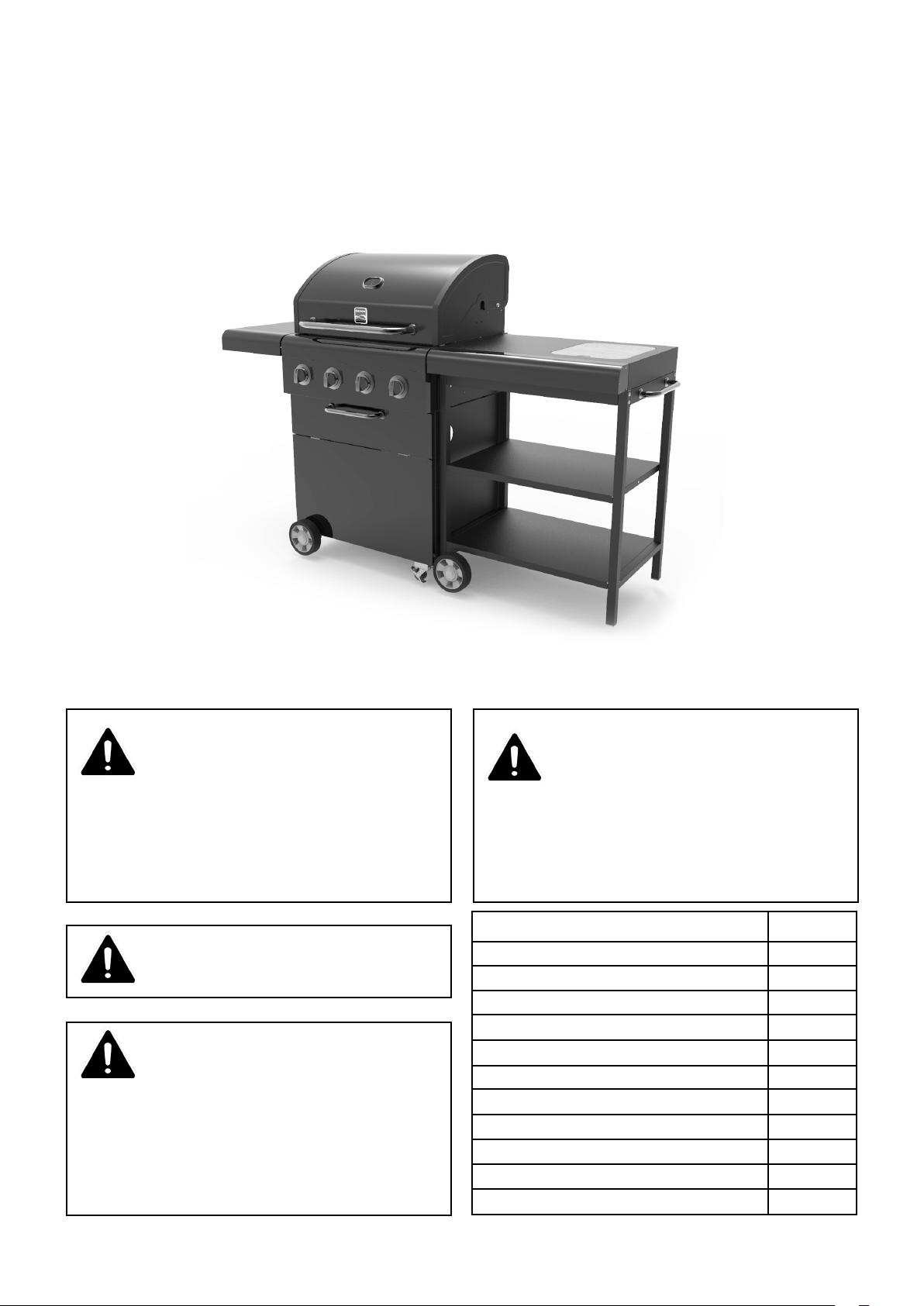
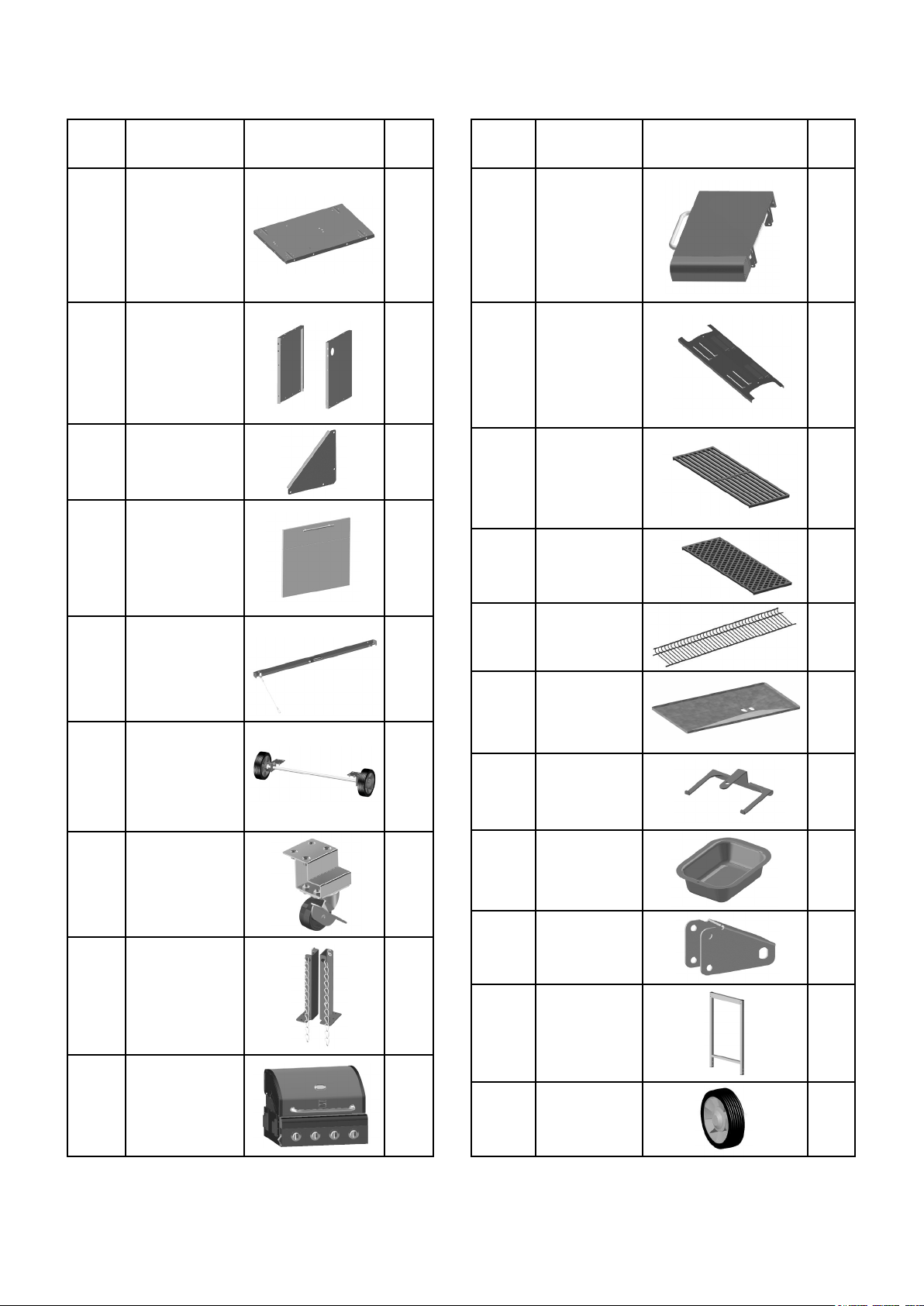
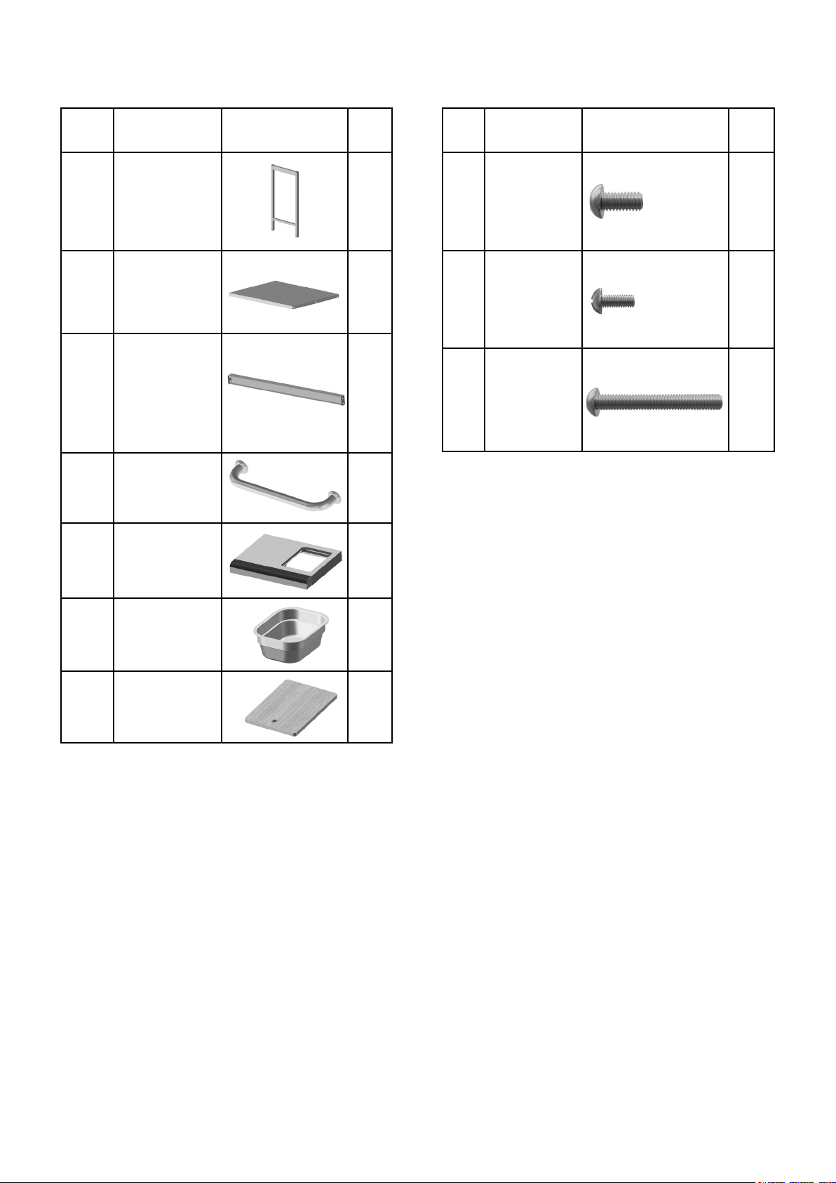
Ref Description Illustration Qty Ref Description Illustration Qty
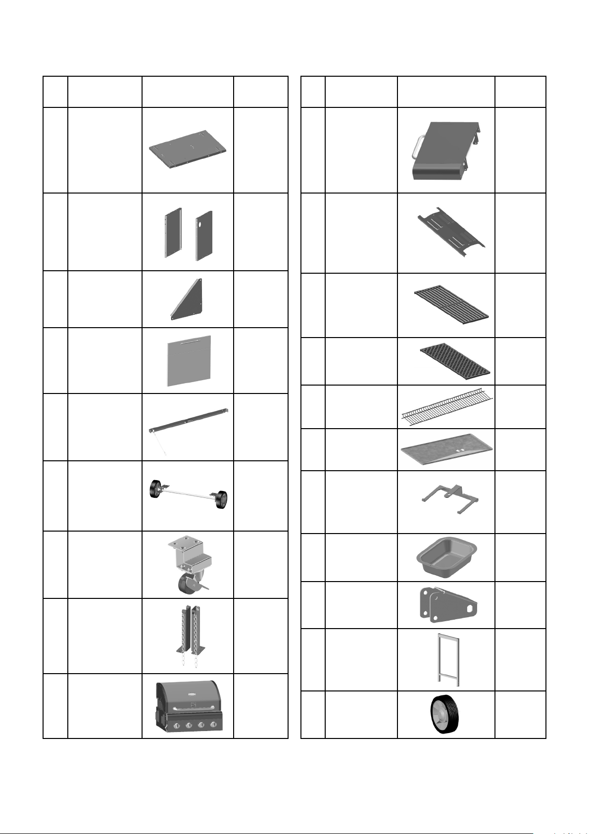
Parts Supplied
10
11
12
13
14
15
16
17
18
19
20
1
4
3
1
1
1
1
1
2
1
2
Fold-down
Side Shelf
Vaporising
Bar
Cooking
Grate
Searing
Grate
Warming
Rack
Grease
Tray
Grease Cup
Bracket
Grease
Cup
Cart Wheel
Bracket
Left Cart
Frame
Cart
Wheel
1
2
3
4
5
6
7
8
9
Cabinet Base
Left + Right
Side Wall
Cabinet
Brace Plate
Cabinet
Front Panel
Cross Bar
Axle
Assembly
Locking
Caster
Wheel
Cylinder
Supports
Firebox
1
1
2
1
1
1
2
1
1
5
Ref Description Illustration Qty
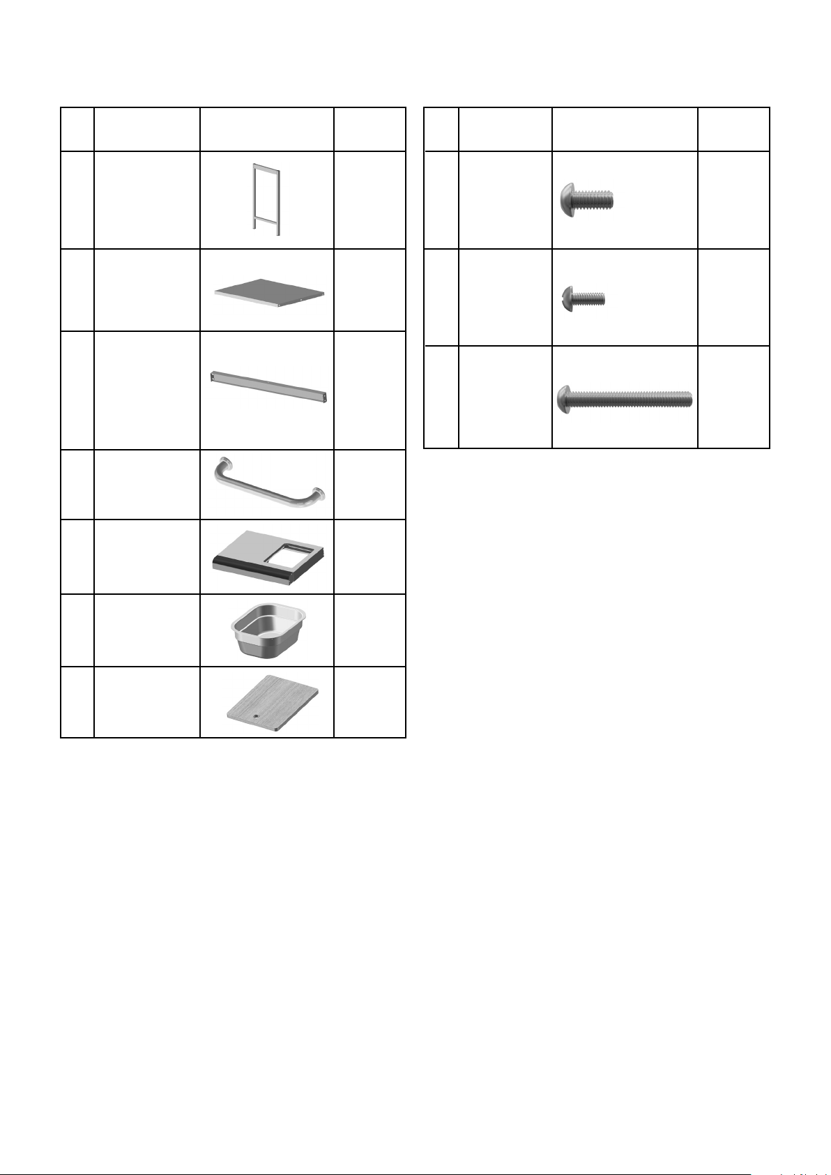
Parts Supplied
21
22
23
24
25
26
27
Right Cart
Frame
Cart Shelf
Cart Rail
Side Cart
Handle
Side Cart
Tabletop
Utility Bin
Chopping
Board
1
2
2
1
1
1
1
Hardware Supplied
Ref Description Illustration Qty
A
B
C
Hardware items are not shown at actual
size.
Before You Start
Check the contents of the box and make sure
you have all the parts and ttings listed. If not,
call 1-844-553-6667.
When you are ready to start, make sure that you
have the right tools at hand, plenty of space and
a clean dry area for assembly.
Assembly
Lay out all nuts and bolts and check lengths
before assembly. It is recommended that the
carton is cut open and spread out on the
oor and used as a protective surface during
assembly. Refer to the assembly diagrams as
necessary.
CAUTION: While every precaution has been
made in the manufacture of this product, care
must be taken during assembly in case sharp
edges are present.
M6 x 12
Bolt
M4 x 10
Bolt
M6 x 45
Bolt
74
4
8
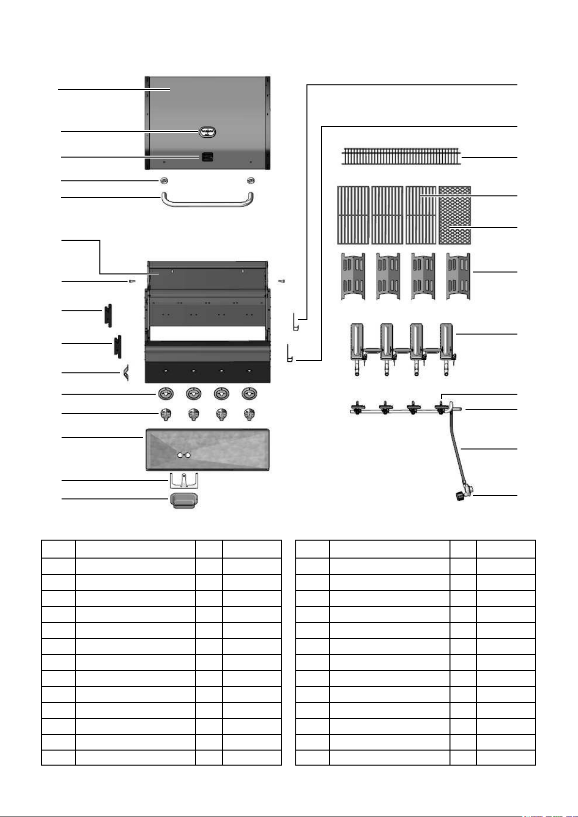
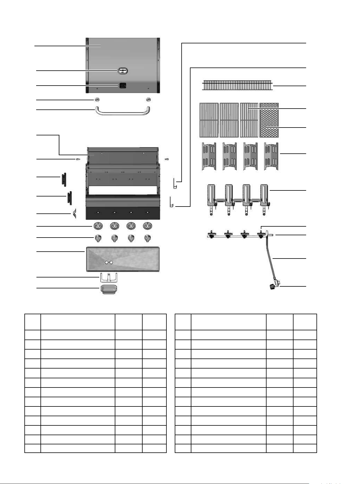
Diagram
6
Part List
Key Description Qty Part Number
Lid
Temperature Gauge
Logo
Lid Handle Bezel
Lid Handle
Firebox
Rotate Rod
Left Back Side Shelf Bracket
Left Front Side Shelf Bracket
Right Back Side Bracket
Right Front Side Bracket
Bottle Opener
Bezel Control Dial
A01
A02
A03
A04
A05
A06
A07
A08
A09
A10
A11
A12
A13
1
1
1
2
1
1
2
1
1
1
1
1
4
Key Description Qty Part Number
Control Dial
Grease Tray
Grease Cup Bracket
Grease Cup
Warming Rack
Cooking Grate
Searing Grate
Vaporising Bar
Burner
Gas Valve
Manifold
Gas Hose
Regulator
A14
A15
A16
A17
A18
A19
A20
A21
A22
A23
A24
A25
A26
4
1
1
1
1
3
1
4
4
4
1
1
1
506 A01
506 A02
506 A03
506 A04
506 A05
506 A06
506 A07
506 A08
506 A09
506 A10
506 A11
506 A12
506 A13
506 A14
506 A15
506 A16
506 A17
506 A18
506 A19
506 A20
506 A21
506 A22
506 A23
506 A24
506 A25
506 A26
A01
A02
A03
A04
A05
A06
A07
A08
A09
A12
A13
A14
A15
A16
A17
A10
A11
A18
A19
A20
A21
A22
A23
A24
A25
A26
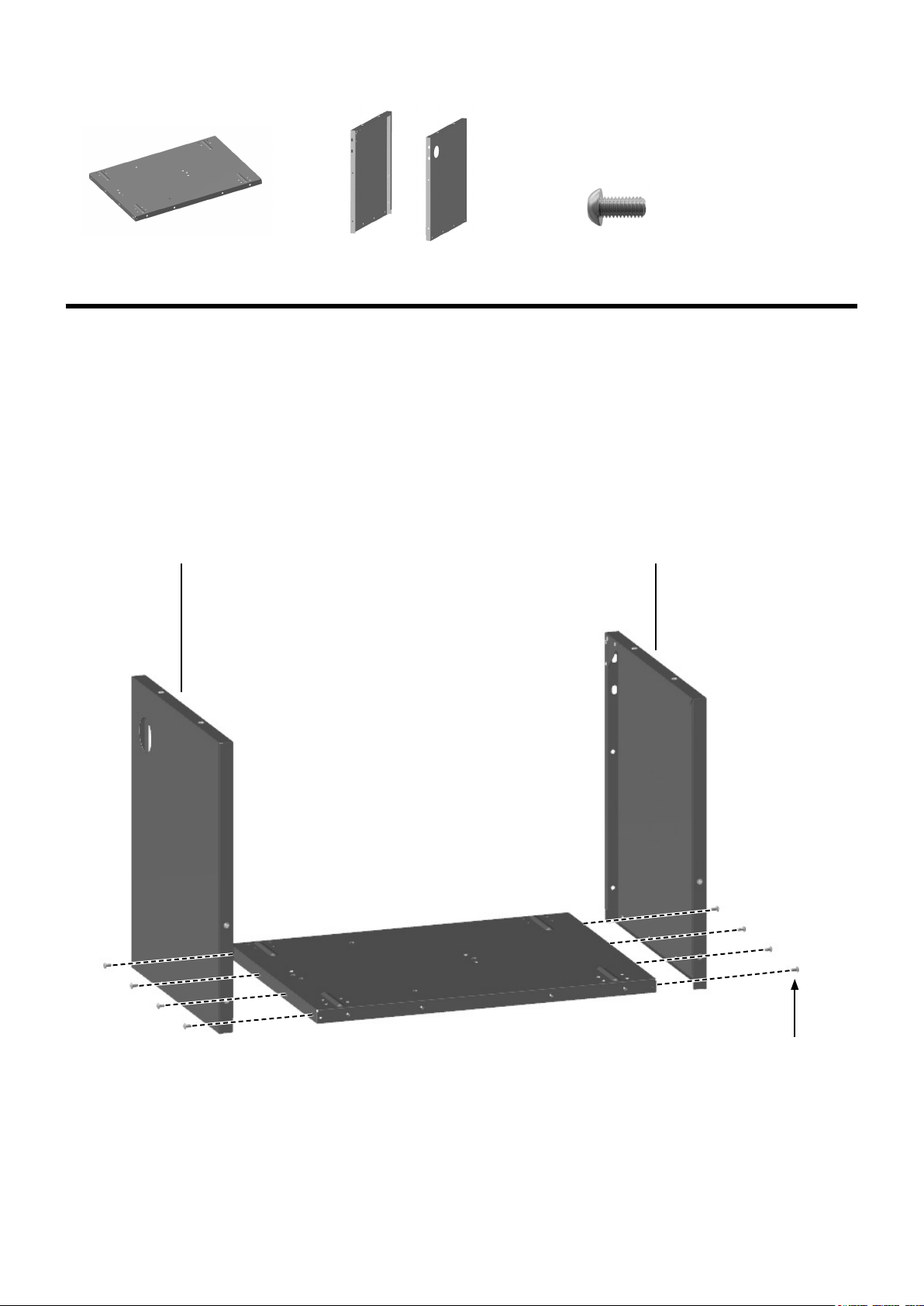
Assembly Step 1
7
Fit left and right side walls to the cabinet base as shown below using 8 of the M6 x 12 bolts.
Note: The right side wall has a hole in the top corner.
This is a view from the back.
Cabinet Base
M6 x 12 Bolt
Left + Right Side Wall
Right Side Wall Left Side Wall
M6 x 12 Bolt
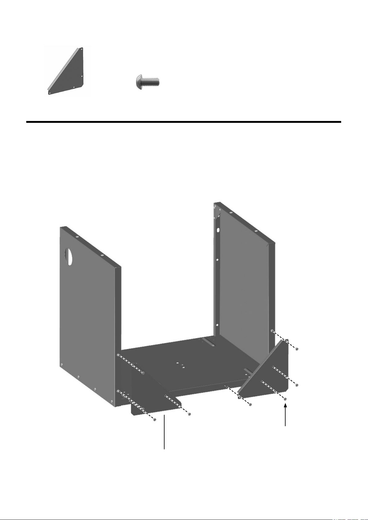
Assembly Step 2
8
Fit the two cabinet brace plates to the cabinet base and side wall assembly using 8 of the M6 x 12 bolts as
shown below.
Cabinet Brace Plate (x2)
M6 x 12 Bolt
Cabinet Brace Plate
M6 x 12 Bolt
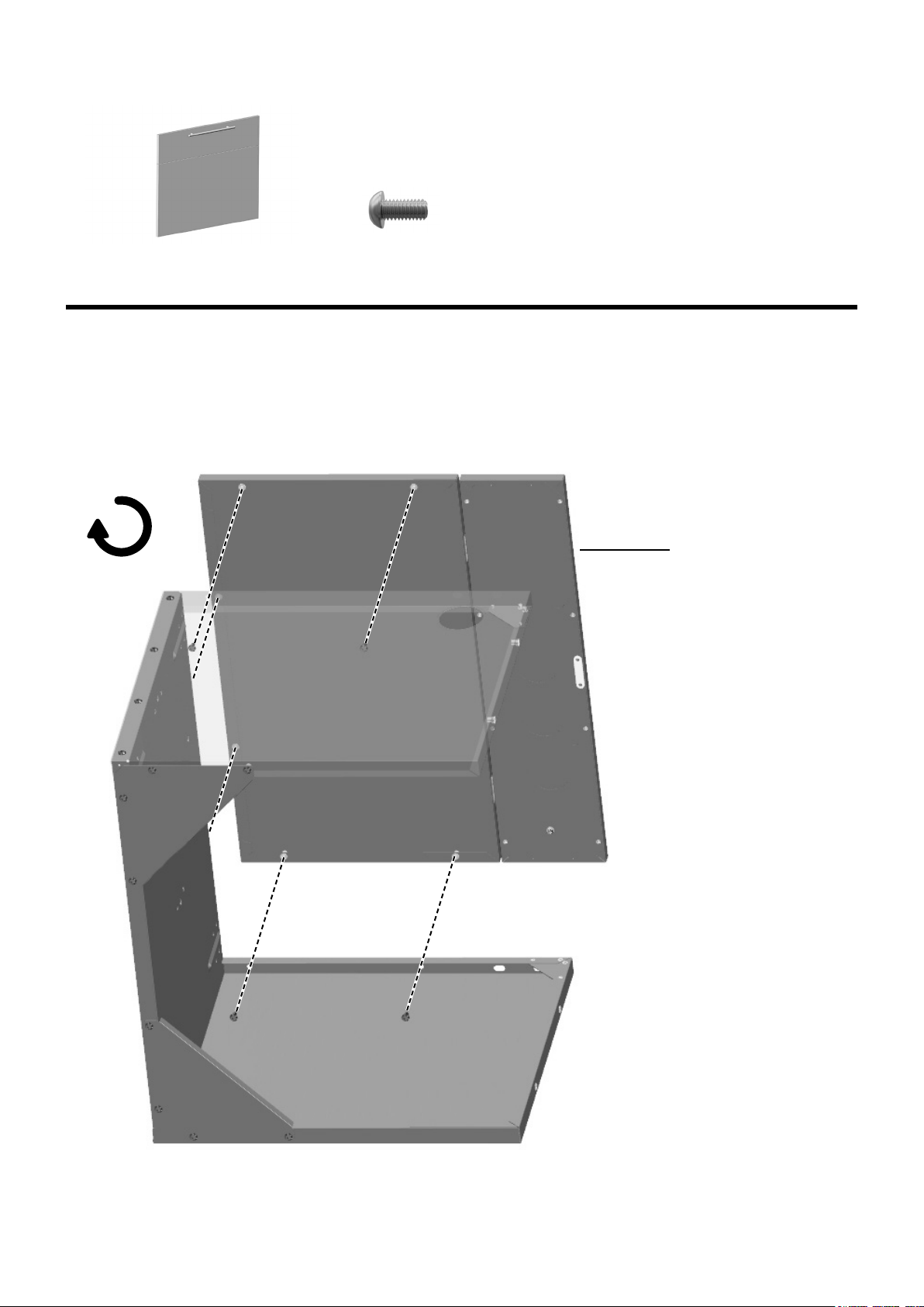
Assembly Step 3
9
Note: Flip cabinet assembly over so that the left side wall is on the oor.
Fit cabinet front panel to base and side wall assembly as shown below using 6 of the M6 x 12 bolts.
Note: An extra person will be needed to hold the door in position while tightening the bolts.
Cabinet Front Panel
Cabinet Front Panel
M6 x 12 Bolt
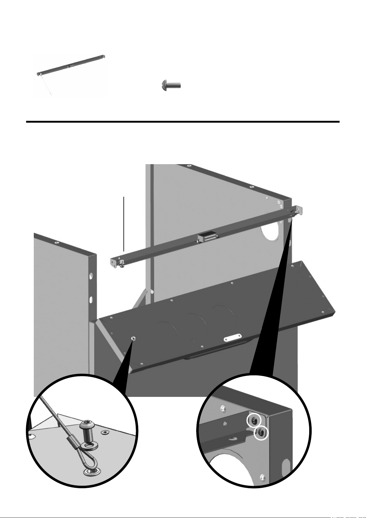
Assembly Step 4
10
Fit the cross bar using 4 of the M4x10 bolts.
Secure chain to cabinet front panel using the pre-tted M6 x 12 bolt and washer.
M4 x 10 Bolts
Cross Bar
Cross Bar
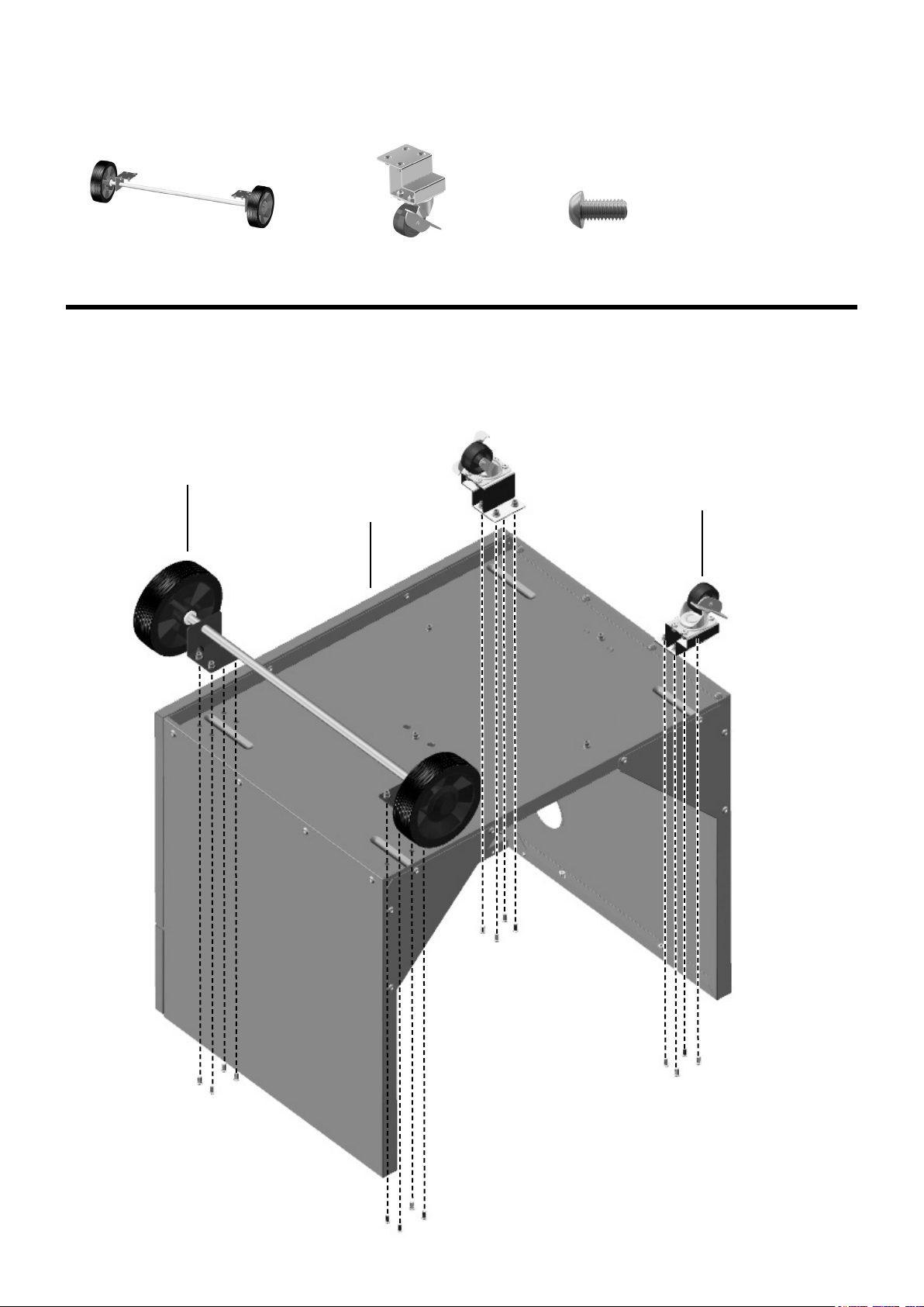
Assembly Step 5
11
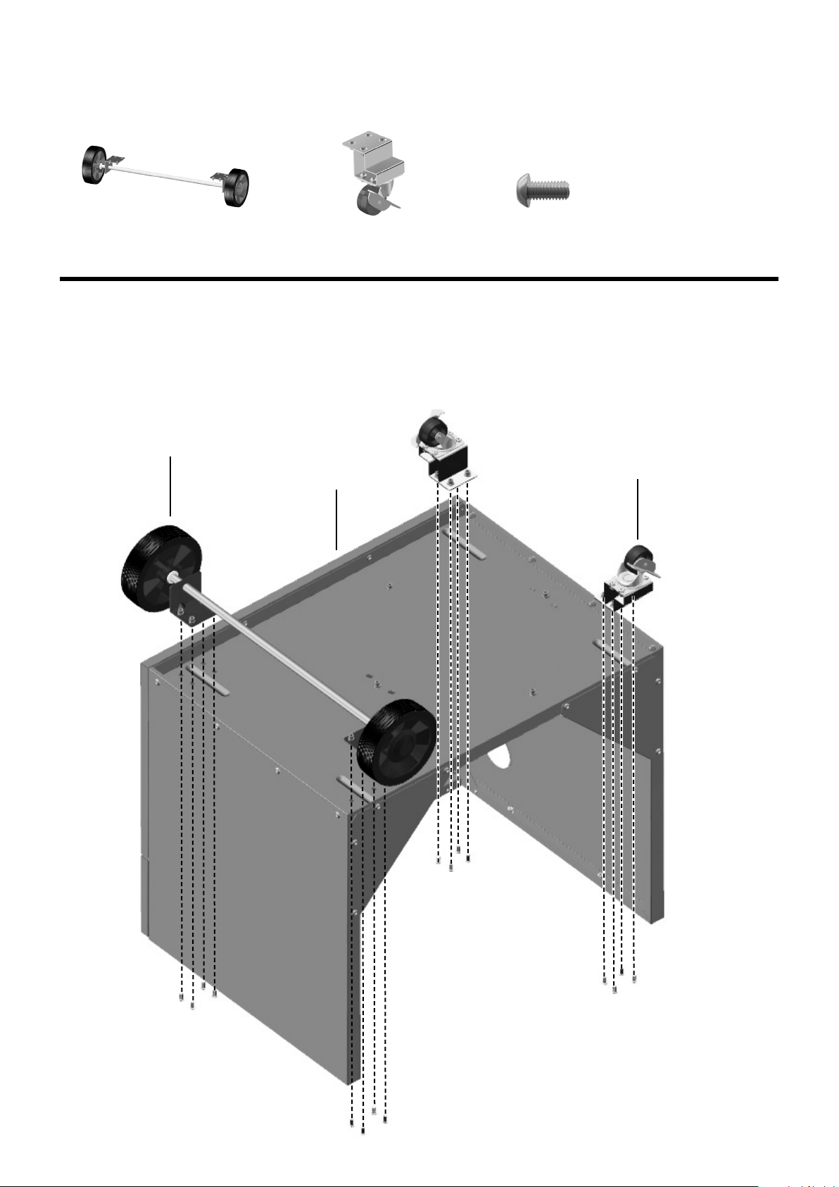
Turn the cabinet assembly over and t axle assembly and two locking caster wheels to the underside of the
cabinet base using 16 of the M6 x 12 bolts.
Note: Axle side with cutout goes to back side of cart.
Note: Once grill is assembled and rolled into position, press caster levers down to lock casters in place.
Always detach side cart from grill when moving grill.
Axle Assembly
Locking Caster
Wheel (x2)
Axle Assembly
Locking Caster
Wheel
Cabinet Base
M6 x 12 Bolt
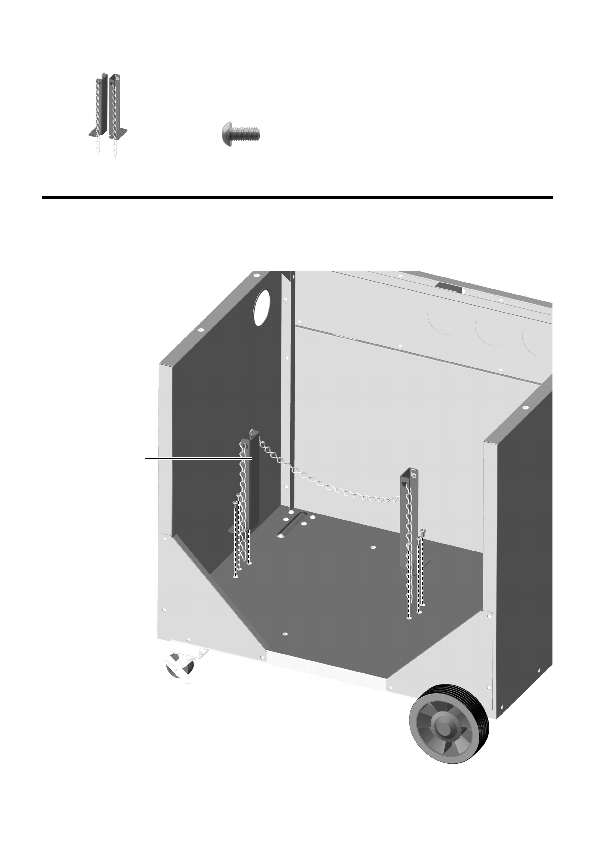
Assembly Step 6
12
Turn the cabinet assembly over and t the two cylinder supports to the cabinet base using 6 of the M6 x 12
bolts.
Cylinder Supports
Cylinder Support
M6 x 12 Bolt
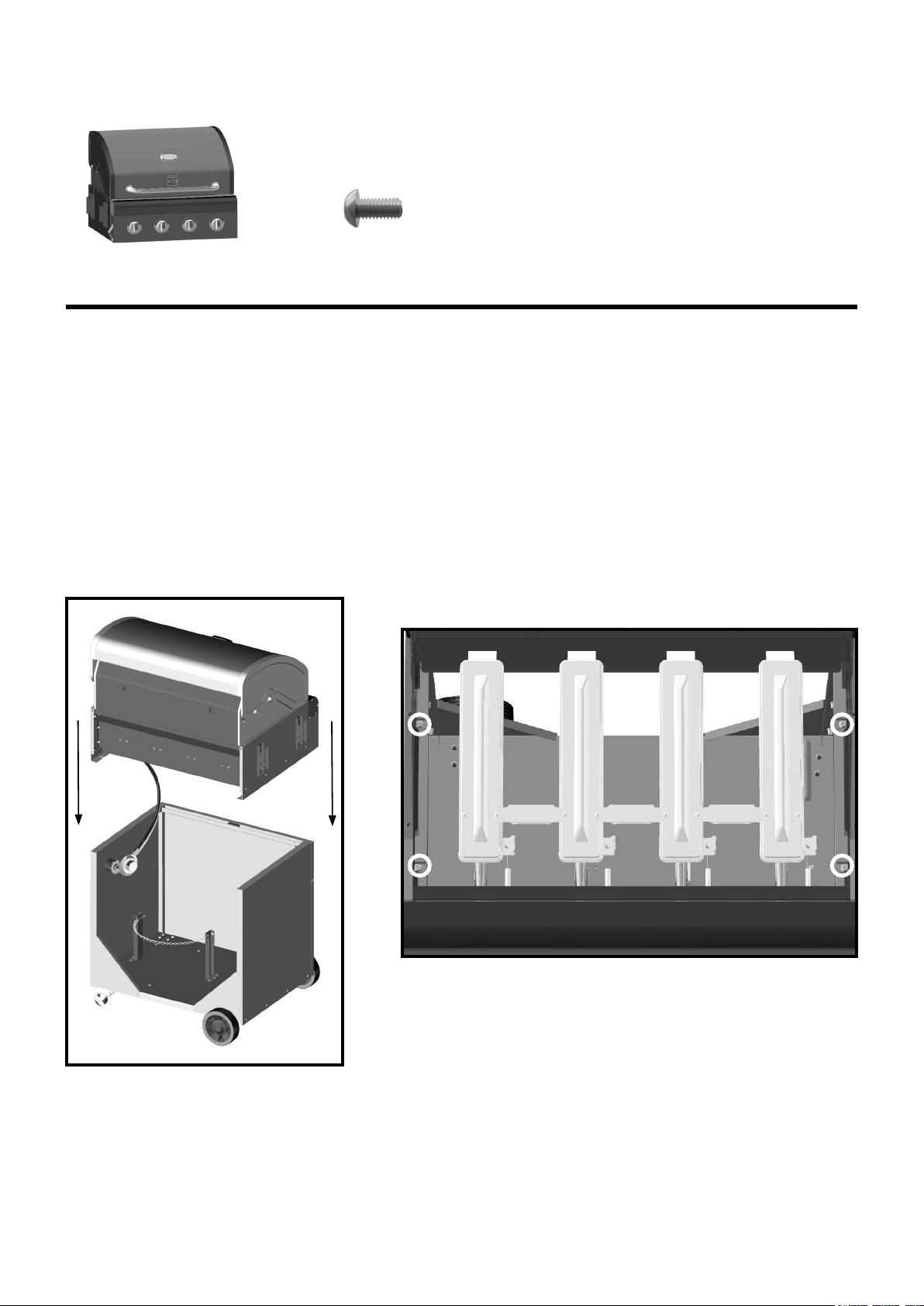
Assembly Step 7
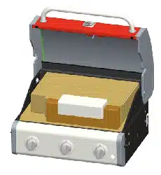
13
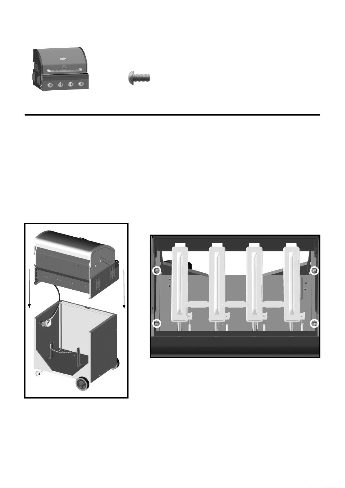
Firebox
Cut the zip ties securing regulator and hose to underside of rebox. Allow hose to hang straight down when
lowering rebox onto cart.
Position rebox onto cabinet. Open hood and use 4 of the M6 x 12 bolts to secure rebox into position. Be
sure that edges of rebox are even with edges of cart before tightening bolts.
Note: Attachment holes are located on inside of rebox (2 on each side).
Note: Two people are required to lift rebox into position.
M6 x 12 Bolt

R-clip and pin
Long bar
Assembly Step 8
14
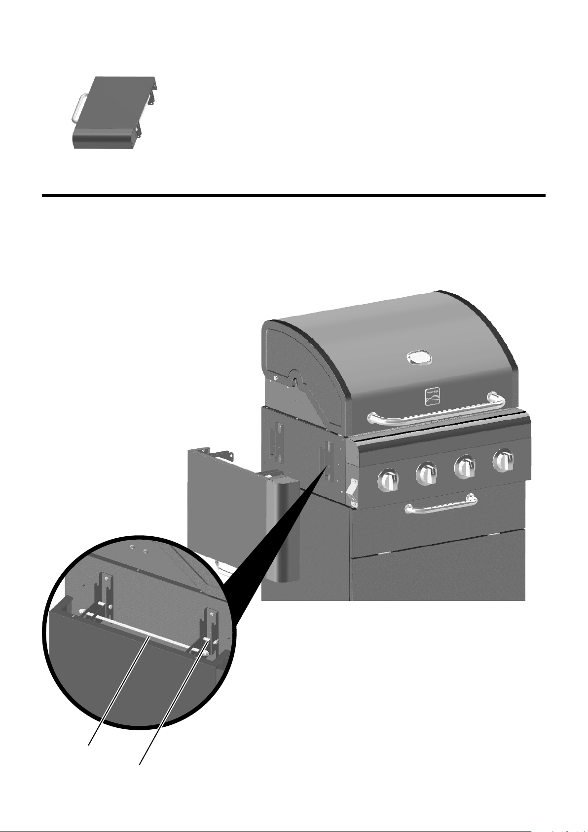
Fold-down Side Shelf
Remove the pre-tted R-clips and pins from brackets on side of rebox.
Insert the shelf brackets into the rebox brackets and align the holes. Reinsert pins and clips through the
holes to secure the shelf in place.
To raise the shelf to use position, lift shelf up and hold it against side of rebox with one hand. Use other
hand to reach below shelf to lift up long bar and insert it into rebox bracket hooks. To fold shelf down,
reach below shelf to lift up long bar with one hand, and gently lower shelf with other hand.
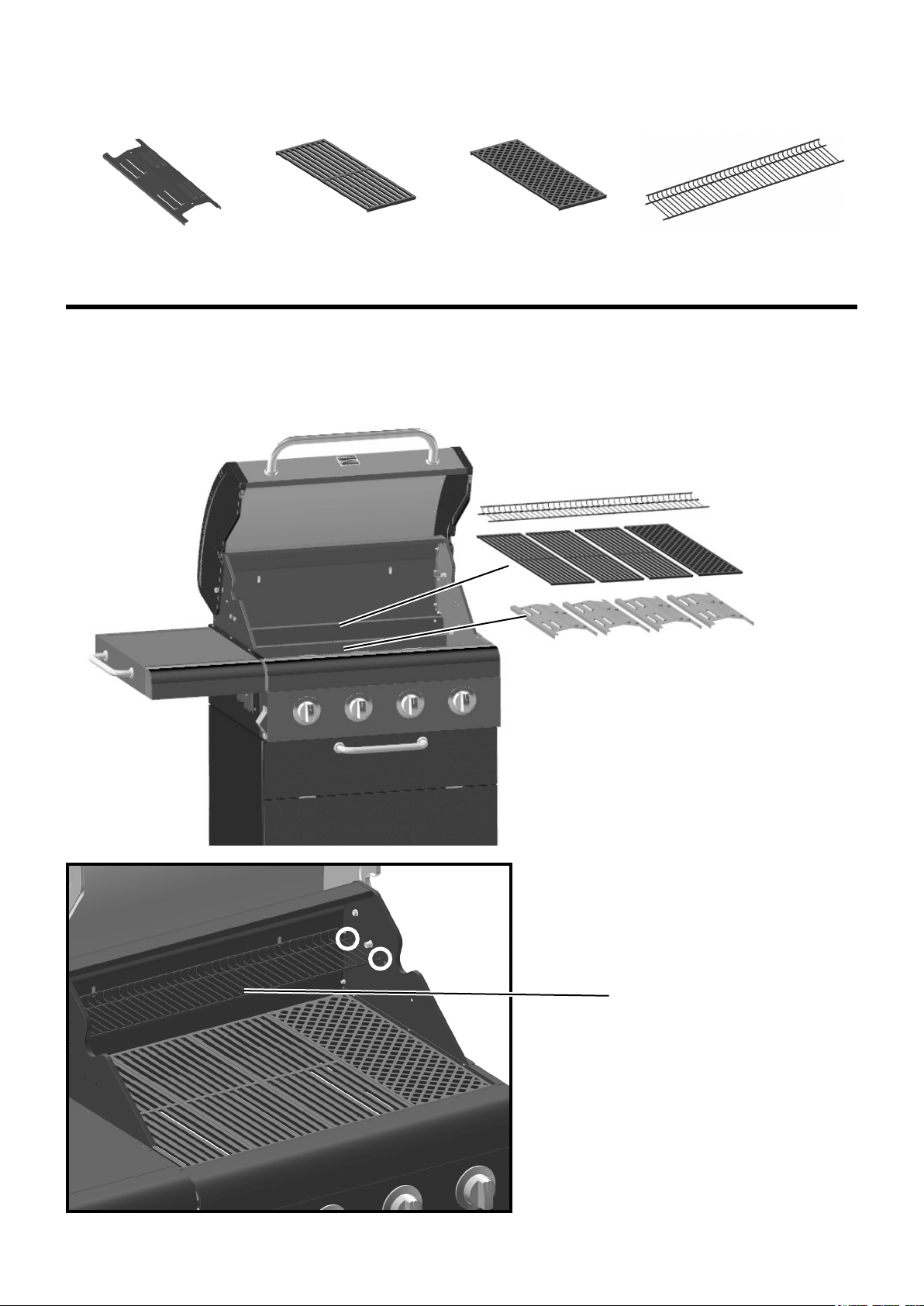
Warming Rack
Assembly Step 9
15
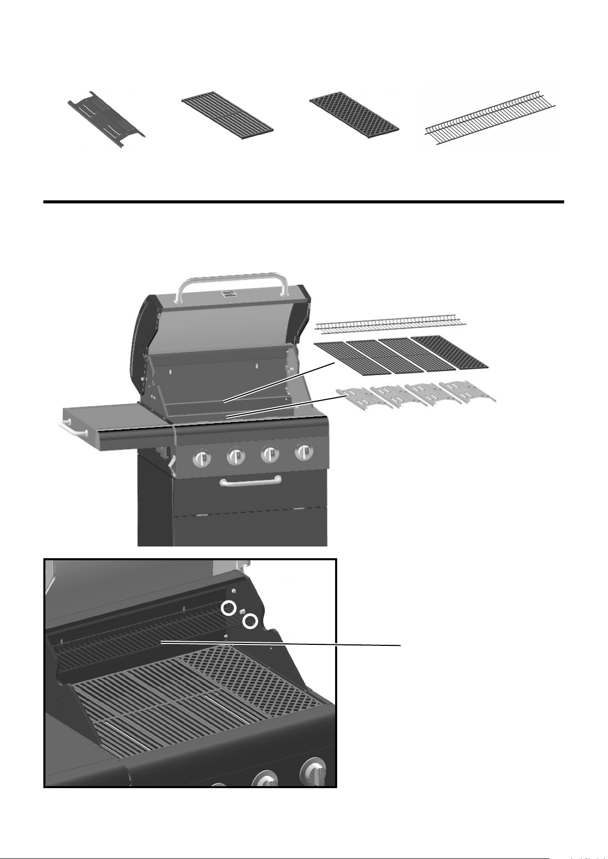
1. Fit vaporising bars (x4) into position as shown.
2. Fit cooking grates (x3) and searing grate into position as shown.
3. Fit warming rack into position as shown.
Note: As a convenience feature, there is a bottle opener on the left side of the rebox.
1.
2.
3.
Vaporising Bar (x4) Cooking Grate (x3) Searing Grate Warming Rack
Note: The Searing Grate must be
positioned over the Searing Burner. For
searing purposes the Searing Burner
(14000 BTU) is hotter than the other
three burners (11700 BTU). The Searing
Grate design is also dierent than the
other three grates. Its diamond check
pattern will sear into the surface of the
meat.

Assembly Step 10
16
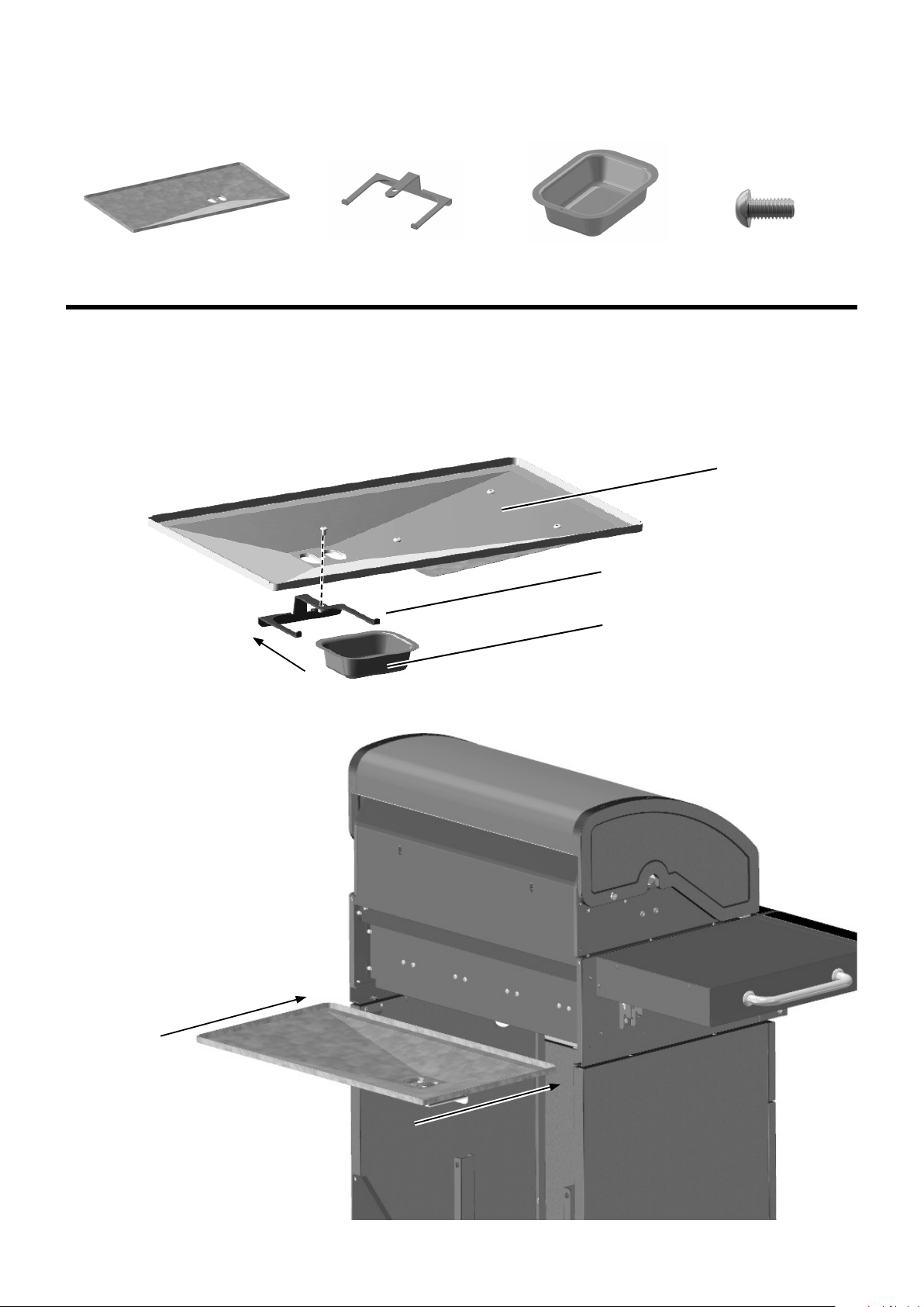
Attach grease cup bracket to grease tray using one of the M6 x 12 bolts and then slide tray into the back
of the grill as shown below. Open the front panel door and slide grease cup into the grease cup bracket as
shown.
Note: Access the grease cup to remove for cleaning by lowering the front panel door. Also, as a
convenience feature, there are three beverage container holder recesses on the inside of the door.
Grease Tray
Grease Cup Bracket
Grease Tray
Grease Cup Bracket
Grease Cup
Grease Cup
M6 x 12 Bolt
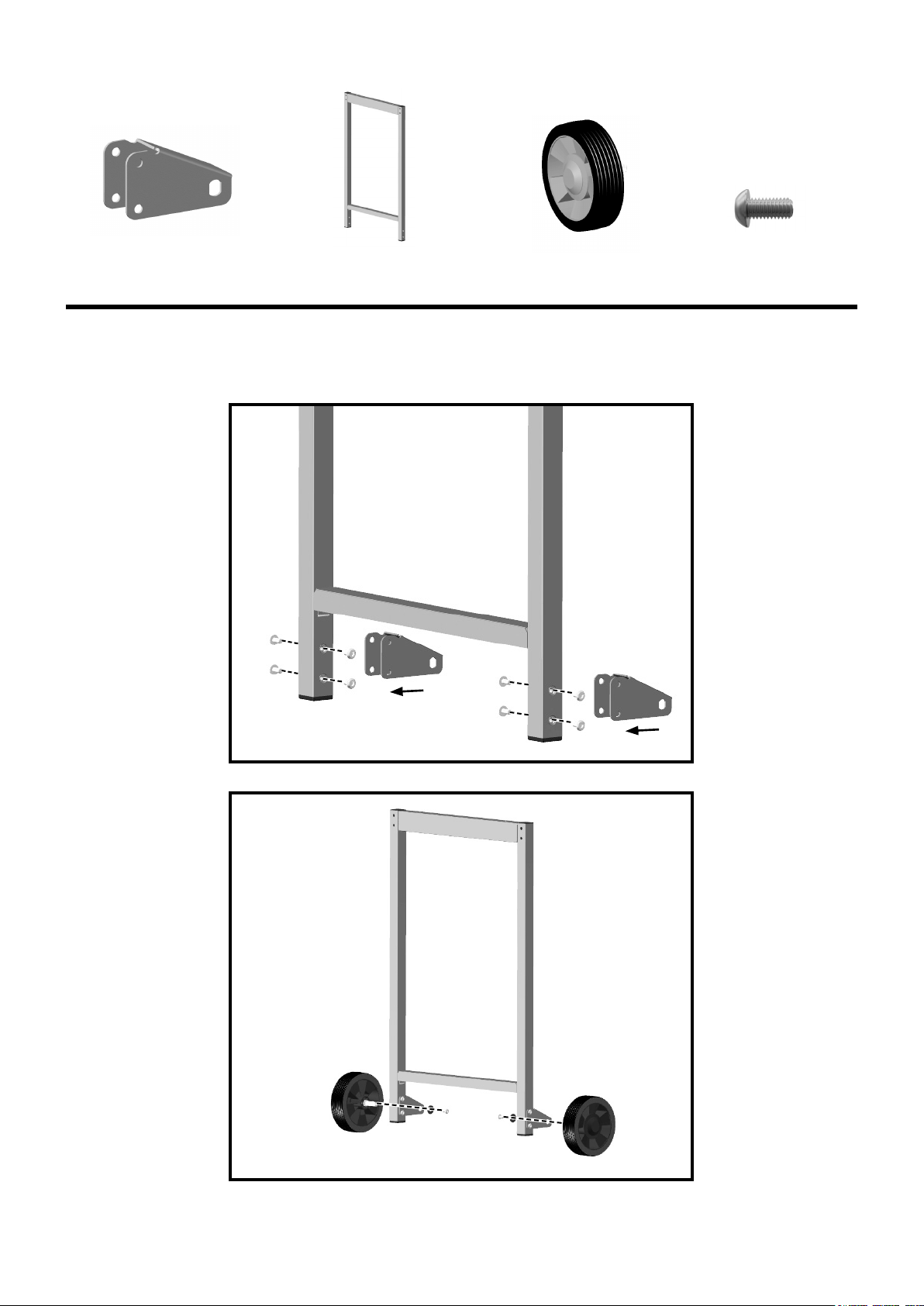
Assembly Step 11
17
Cart Wheel (x2)Cart Wheel Bracket (x2) Left Cart Frame
M6 x 12 Bolt
1. Fit cart wheel brackets to left cart frame as shown below using 8 of the M6 x 12 bolts.
2. Fit the 2 cart wheels to the cart wheel brackets using pretted bolt and washer attached to the tip of the
wheel axles.
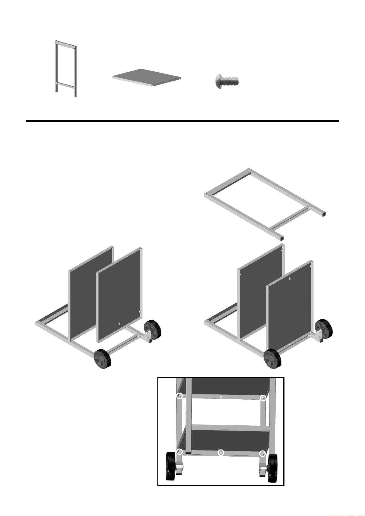
Assembly Step 12
18
Lay the left cart frame down and attach the middle cart shelf rst using 2 of the M6 x 12 bolts. Then attach
the bottom cart shelf using 3 of the M6 x 12 bolts (Ref A).
Then attach the right cart frame to the assembled
shelves using 5 of the M6 x 12 bolts (Ref A).
Note: There are 3 height options for the shelves.
Note: Bolt attachment points are located
underneath the cart shelves.
Right Cart Frame
Cart Shelves (x2)
M6 x 12 Bolt
Assembly Step 13
19
Fit the two cart rails to cart frame as shown using 8 of the M6x45 bolts.
Note: Be sure to attach the Cart Rails with the wide side facing up.
Cart Rail (x2)
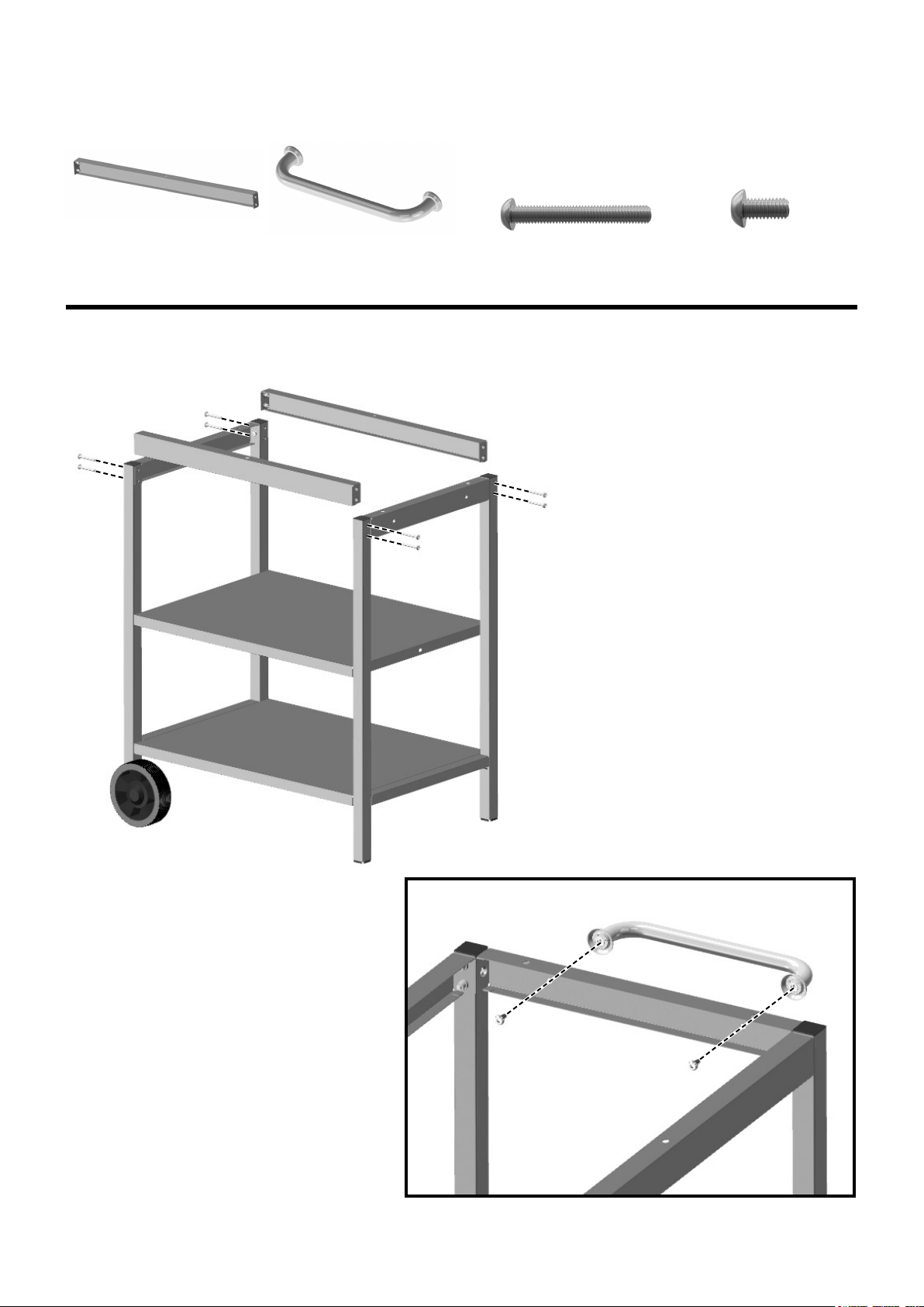
Attach the side cart handle to the top of
the right cart frame with 2 M6 x 12 Bolts.
Side Cart Handle M6x45 Bolt
M6 x 12 Bolt
Assembly Step 14
20
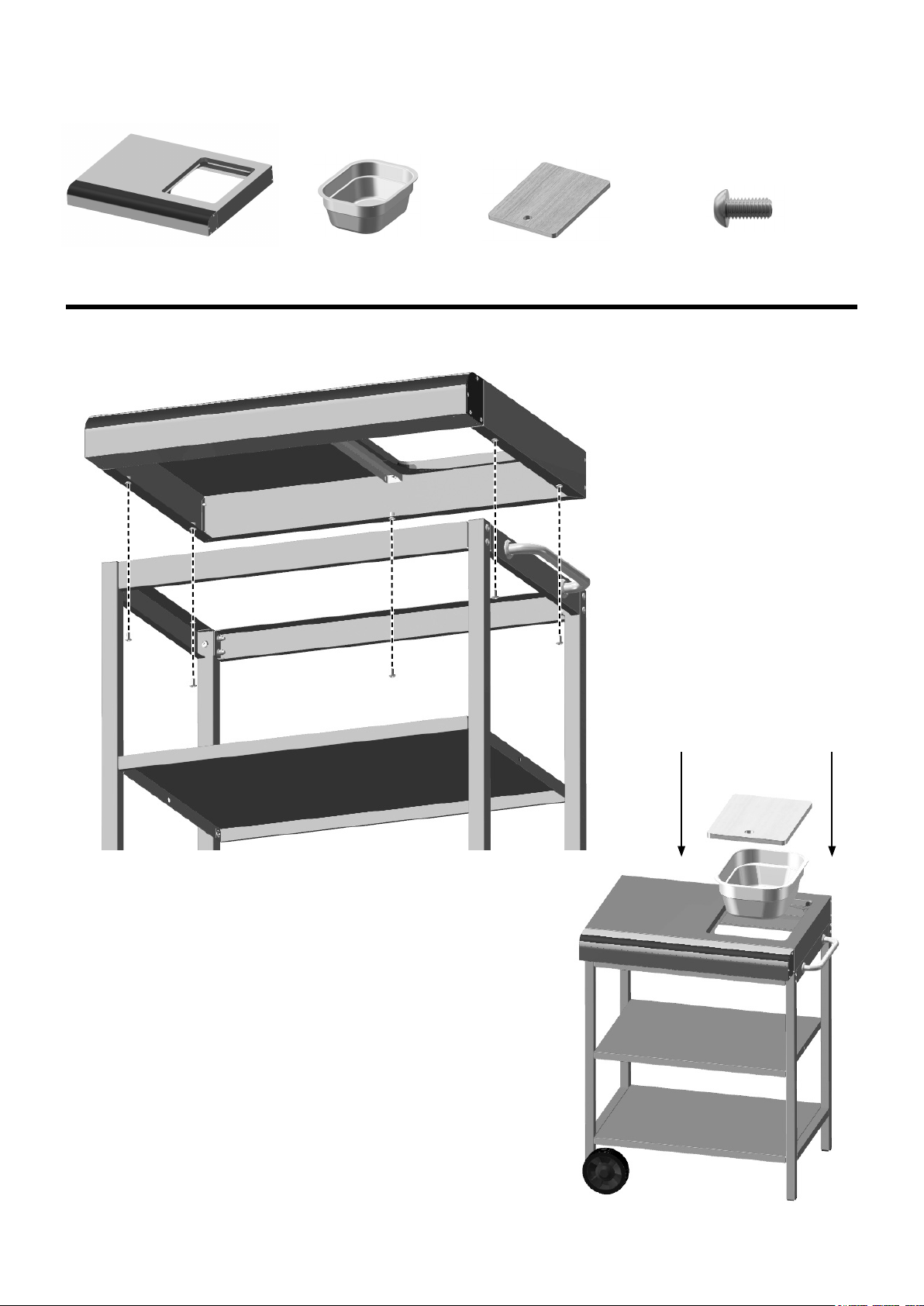
Attach the side cart tabletop to the cart frame using 5 of the M6 x 12 Bolts (Ref A).
Side Cart Tabletop Utility Bin Chopping Board
Place utility bin and chopping board into the side cart
tabletop as shown.
M6 x 12 Bolt (Ref A)

21
Assembly Step 15
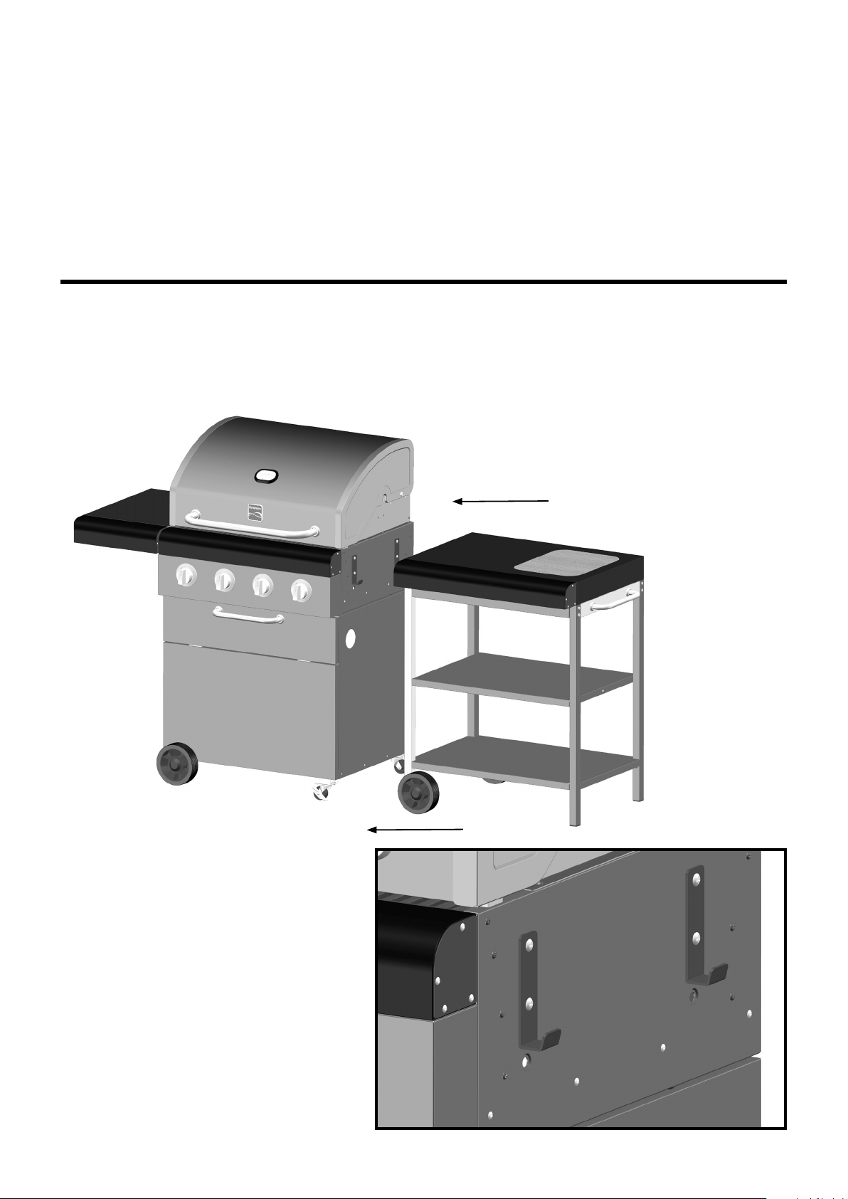
To t the cart to the grill body, lift the cart slightly on the left and lower down to hook onto the grill side
brackets.
Note: Make sure the side cart wheels are on the left hand side. If you wish to keep the side cart detached,
you can remove the side brackets from the grill.
Note: Always detach the side cart from the grill when moving grill.
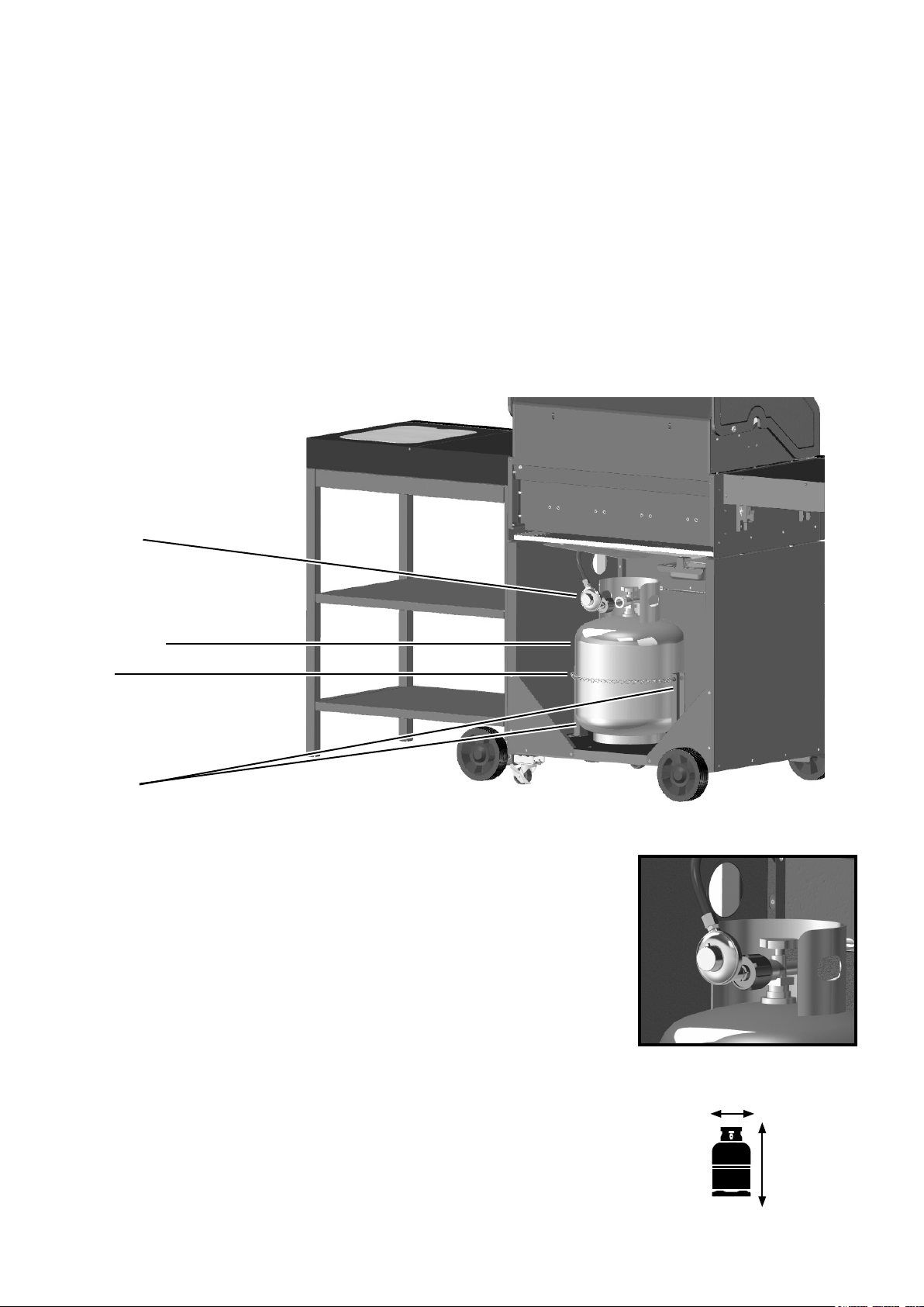
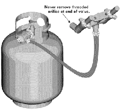
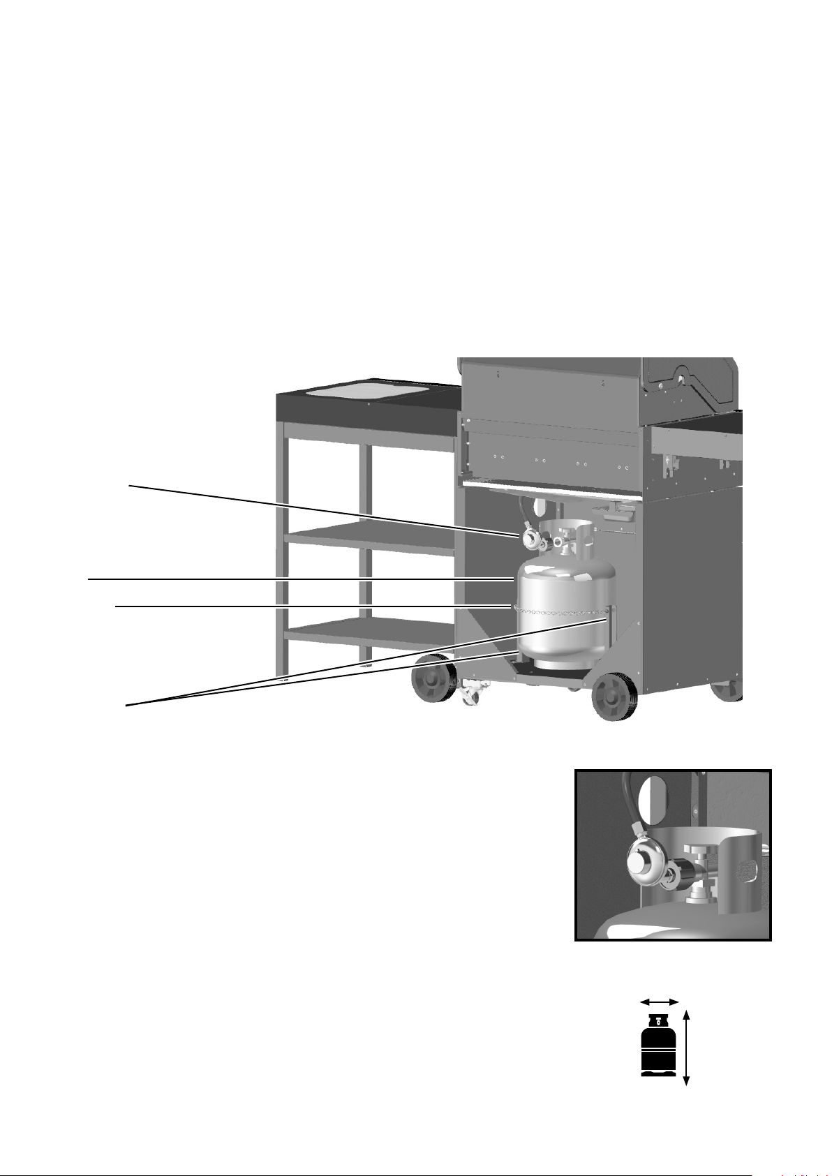
Load gas cylinder into the cabinet through the back, positioning it against the chain between the two
cylinder supports, and then securing it by hooking together the two loose chain ends.
Connect the gas cylinder to the regulator as shown. Perform leak test (see page 23).
Use cabinet front panel for easy access to gas hose and regulator.
Note: Grease cup needs to be on the opposite side to the gas cylinder.
Screw regulator onto
gas cylinder.
When connecting the exible hose ensure that it is not subjected to twisting.
Use LP gas cylinder, max height 17.75 inches, width 12.25 inches and weight
20 lbs.
12.25"
17.75"
Assembly Step 16
Gas Cylinder
Cylinder
Supports
Chain
Regulator
22
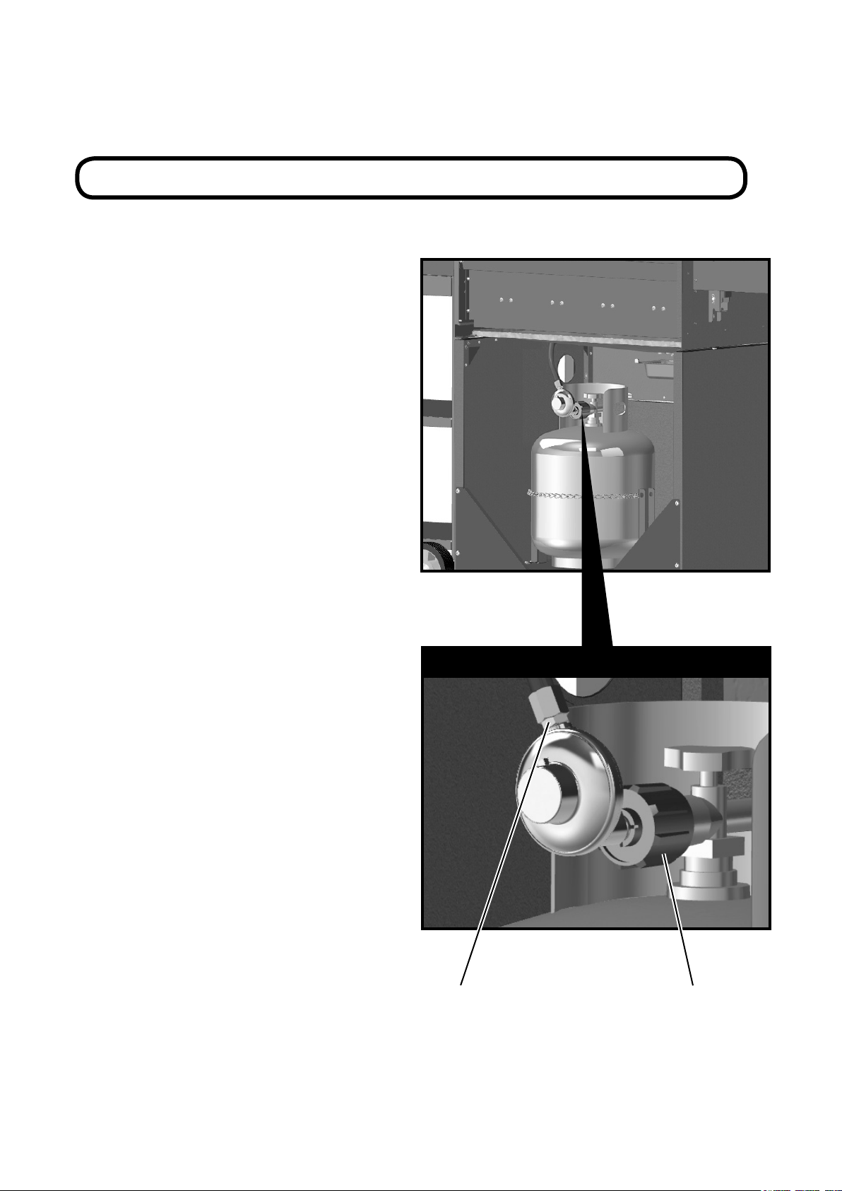
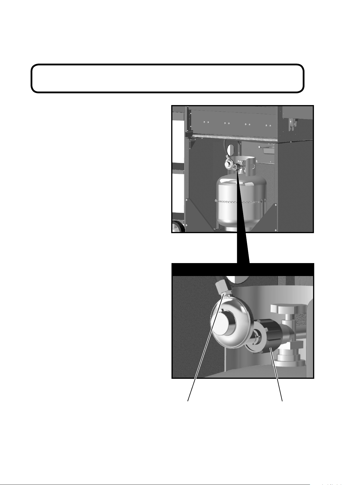
Assembly Step 17
Leak Testing
Your grill has been checked at all factory
connections for leakage. To be performed in a well
ventilated area. Conrm all control knobs are in
the o position. To check the connection at the gas
hose/regulator/cylinder:
1. Make leak test solution by mixing 50%
water with 50% liquid dish soap.
2. Brush several drops of the solution
onto the gas hose/regulator/cylinder
and hose connection.
3. Turn on the gas cylinder valve.
Inspect the connections and look for bubbles.
NEVER USE AN OPEN FLAME to test for leaks
at any time.
4. If no bubbles appear the connection is safe.
5. If bubbles appear, there is leakage.
Turn o gas supply and re-tighten all joints.
Repeat test. If bubbles form again, do not use the
grill. Please contact the helpline stated in this
manual.
Leak test annually and whenever the gas bottle is
removed or replaced.
NOTE: Leak Test to be performed before using the appliance.
Hose / Regulator Regulator / Cylinder
Points for leak testing
23

SAFETY INSTRUCTIONS
Warnings
• Failure to read and follow these instructions could
result in serious injury or damage to property.
• This product is for OUTDOOR USE ONLY.
• This product shall not be used in a building,
garage or any other enclosed area.
• This outdoor cooking gas appliance is not
intended to be installed in or on boats.
• This product shall not be installed in or on
recreational vehicles.
• Positioning - ensure the unit is a minimum of 40
inches (1m) from ammable items or structure
from all sides and above.
• This product shall not be used under overhead
combustible construction.
• Always position the gas cylinder as instructed in
this manual – always keep the cylinder vertical.
• Important – Ensure the grill is positioned on
at level ground to aid with fat/grease run o.
• Important – LEAK TEST THE GRILL WHEN
FULLY ASSEMBLED BEFORE FIRST USE. IN
ADDITION always leak test the unit annually,
when dismantled, when parts are replaced, or if
the gas cylinder is removed or replaced. FAILURE
TO DO THIS COULD CAUSE SERIOUS INJURY,
OR DAMAGE TO THE GRILL.
• Always ensure that changing of the gas cylinder
is carried out away from any source of ignition.
• Do not obstruct the ow of combustion and
ventilation air.
• NEVER use indoor, in an enclosed area or below
ground level.
• The pressure regulator and hose assembly
supplied with the outdoor cooking gas
appliance must be used. Replacement pressure
regulators and hose assemblies must be those
specied by the outdoor cooking gas appliance
manufacturer.
The LP-gas supply cylinder to be used must be:
a. Constructed and marked in accordance with
the specications for LP-gas cylinders of the U.S.
Department of Transportation (D.O.T.), CAN/
CSA-B339, or the Cylinders, Spheres and Tubes
for Transportation of Dangerous Goods and
Commission, as applicable; and
b. Provided with a listed overlling prevention
device; and
c. Provided with a cylinder connection device
compatible with the connection for outdoor cooking
appliances.
24
• The cylinder used must include a collar to
protect the cylinder valve.
Do not store a spare LP-gas cylinder under or near
this appliance. Never ll the cylinder beyond 80
percent full. If the above information is not followed
exactly, a re causing death or serious injury may
occur.
• Other cylinders may be acceptable for use with
the appliance provided they are compatible with
the appliance retention means.
• Place dust cap on cylinder valve outlet whenever
the cylinder is not in use. Only install the type
of dust cap on the cylinder valve outlet that is
provided with the cylinder valve. Other types of
caps or plugs may result in leakage of propane.
• This appliance has been supplied with an LP
REGULATOR (only use with LP gas).
• NEVER use an adjustable regulator with this
grill.
• This product will become hot when in use – take
care when touching.
• Keep children and pets at a safe distance from
the unit when in use.
• DO NOT move this product when in use.
• Always turn o gas supply at the gas cylinder
when not in use.
• Any modication of this grill may be
dangerous.
• DO NOT leave this product unattended when in
use.
• Any parts sealed by the manufacturer or his
agent must not be altered by the user.
• When igniting, always have the lid open.
• ONLY use grill on a at LEVEL non-
ammable surface or ground.
• This grill is not intended for use with
charcoal or other similar fuel.
• DO NOT use gasoline, white spirit, lighter uid,
alcohol or other similar chemicals to ignite a grill.
• When storing the grill or gas cylinder,
ensure they are away from ammable materials
or liquids.
• Always follow care and maintenance instructions
– regularly maintain your grill.
• DO NOT allow grease, fat or food residue to
build up in or on the grill – RISK OF FIRE.
• Always replace worn parts – do not use grill
if a leak, wear, or damage is found.
25
• Never overload the grill with food – evenly space
over the cooking grill surface, ensuring sucient
air circulation to the burners.
• DO NOT store or cover the grill until fully
cooled.
• Keep outdoor cooking appliance area clear and
free from combustible materials, gasoline and
other ammable vapors and liquids.
• Do not empty the grease tray until the grill
has cooled down.
• This product is not suitable for Lava Rock.
• Retain instructions for future reference.
• Installation must conform with local codes or, in
the absence of local codes with either the
National Fuel Gas Code, ANSI Z223.1/NFPA 54,
Natural Gas and Propane Installation Code. CSA
B149.1, or Propane Storage and Handling Code,
B149.2
ALTHOUGH EVERY PRECAUTION HAS BEEN
TAKEN TO ELIMINATE SHARP EDGES, ALWAYS
TAKE CARE WHEN HANDLING METAL
COMPONENTS.
Do Not Bring Goods Back To Place Of Purchase.
USER INSTRUCTIONS
Connecting to the Cylinder
• Conrm all grill control knobs are in the o
position and ensure gas is turned o.
• Connect the regulator to the gas cylinder
according to your regulator and cylinder dealer’s
instructions.
Use Instructions - Grill
Before proceeding, make certain that you
understand the WARNINGS section of this manual.
• Preparation before cooking – To prevent foods
from sticking to the cooking grill, apply a light
coat of cooking or vegetable oil to food before
barbecuing session.
• Note: When cooking for the rst time, paint
colors may change slightly as a result of high
temperatures. This is normal and should be
expected.
• Inspect the hose before each use of the outdoor
cooking gas appliance.
• If it is evident there is excessive abrasion or
wear, or the hose is cut, it must be replaced prior
to the outdoor cooking gas appliance being put
into operation. The replacement hose assembly
must be identical to the original part. See Part
List.
Lighting the Grill
• Turn on gas supply at gas cylinder.
• Push control dial in and slowly turn to
position.
• If burner does not light, return to
position
and try again.
• Once ignition has occurred, hold dial in for at
least 10 seconds to ensure the burner stays lit.
• If burner does not light or stay lit after holding
dial in for 10 seconds, turn the dial to
position and wait for 1 minute and try again. Do
not continuously hold the dial in as you may
cause a build up of gas.
• In windy conditions shield from wind to ensure
easy lighting.
• Turn control dial to alter burner settings as
required.
To Turn O:
• Push the dial in and turn to the
position.
• Turn the gas o and disconnect at the cylinder
when not in use.
Use Instructions - Side Cart
The customer has the option to secure the side cart
to the grill or to keep it detached. To attach the side
cart to the grill, lift the side cart slighly on the left
and lower down to lock in to the grill side brackets.
Note: make sure the side cart wheels are on the
left hand side. If you wish to keep the side cart
detached, you can remove the side brackets from
the grill.

26
Manual Lighting Instructions
• Remove the searing grill and vapor bar from
barbecue.
• Place a lit match beside the burner (at the same
location as the sparker shield)
• Push and turn the right most control knob anti-
clockwise to the high position.
• After successful lighting, light each burner from
left to right as desired.
• If burner fails to ignite after repeated attempts,
contact the help line number stated in this
manual.
WARNING
• If you smell gas – turn o the grill,
extinguish all ames, open the grill hood. If the
odor continues, immediately contact your gas
supplier.
• In the event of an uncontrollable re, immediately
disconnect the gas cylinder moving it away from
re and contact the re services. DO NOT PUT
YOURSELF AT RISK!
• Ensure aerosols are not used near this unit when
in use.
• Ensure all packaging and plastic bags are
disposed of safely.
Grill Cooking
The Vapor bar evenly distributes the heat across the
cooking grill area. The natural food juices produced
during cooking fall onto the hot vapor bar below
and vaporise. Even cooking of food will be achieved
by using the grill with the hood down. This should
only be done with the burner on low.
Flare-Up Control
IMPORTANT – FLARE UPS CAN OCCUR FROM
RESIDUE FAT AND JUICES DRIPPING ONTO THE
BURNERS AND HOT VAPOR BAR. To reduce this,
regularly clean the burners and vapor bar. To control
are-ups, it is advisable to trim away excess fat
from meat and poultry before grilling. The burners
should always be placed on the low setting during
cooking. Always protect your hands when handling
anything near the cooking surface of the grill.
End of Cooking Session
After each cooking session, turn the grill burners
to the position and burn for 5 minutes. This
procedure will burn o cooking residue, thus making
cleaning easier.
Care and Maintenance
• Regularly clean your grill between uses and
especially after extended periods of storage.
• Ensure the grill and it’s components are
suciently cool before cleaning.
• Do not leave the grill exposed to outside
weather conditions or stored in damp, moist
areas.
• Never douse the grill with water when its
surfaces are hot.
• Never handle hot parts with unprotected hands.
• In order to extend the life and maintain the
condition of your grill, we strongly
recommend that the unit is covered when left
outside for any length of time, especially during
the winter months.
• IMPORTANT – We recommend that servicing of
this appliance should be performed either after
every 100 hours of use or annually, which ever is
achieved soonest.
• Change the exible tube when the national
conditions require it.
• Keep outdoor cooking gas appliance area clear
and free from combustible materials,
gasoline and other ammable vapors and liquids.
Cooking Grill
• Clean with hot soapy water.
• To remove any food residue, use a mild cream
cleaner on a non-abrasive pad.
• Rinse well and dry thoroughly.
Grill Body
• Regularly remove excess grease or fat from the
grill body with a soft plastic or wooden scraper.
• It is not necessary to remove all the grease from
the body. If you need to clean fully, use hot
soapy water and a cloth, or nylon-bristled brush
only.
• Remove cooking surfaces and burners before full
cleaning.
• Do not immerse the gas controls or manifold in
water.
• Check burner operation after carefully retting
into body.
Burner Maintenance
• In normal usage, burning o the residue after
cooking will keep the burners clean.
• The burners should be cleaned annually, or
whenever heavy build-up is found, to ensure that
there are no signs of blockage (debris, insects) in
either the burner portholes or the venturi tubes
of the burners tted over the valve outlets. A
clogged tube can lead to a re beneath the grill.
Vapor Bar
• Clean the vapor bar with soap and warm water
using a low abrasive cleaning cloth or sponge.
CAUTION: SPIDER ALERT! Spiders or small insects
can create “ashback” problems. The spiders
spin webs or build nests in the grill burner tubes,
obstructing the ow of gas to the burner. The
backed-up gas can ignite in the tube behind the
control panel. This is known as ashback and can
damage your grill or cause personal injury. To
prevent ashback and ensure good performance,
remove and clean the burners before use whenever
the grill has been idle for an extended period.
Cleaning the Burner Assembly
Follow these instructions to clean and/or replace
parts of burner assembly or if you have trouble
igniting grill.
1. Turn gas o at control knobs and LP cylinder.
2. Remove cooking grills, searing grill and vaporiser
bars.
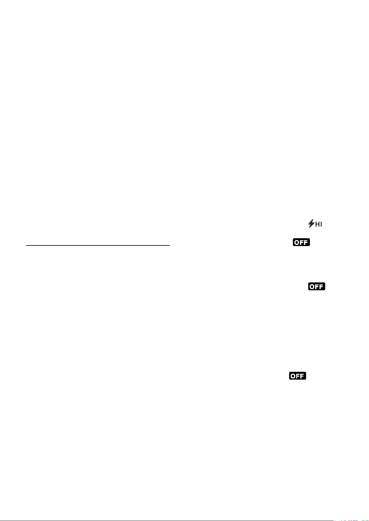
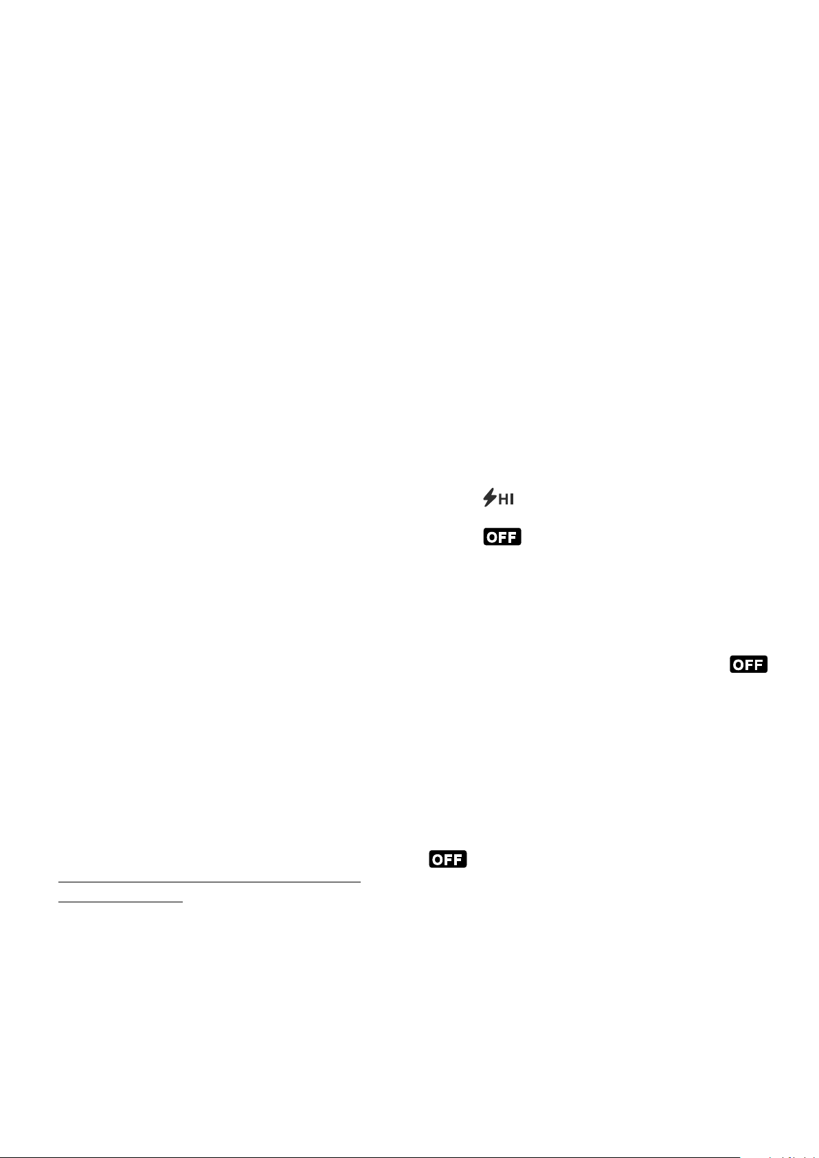
3. Remove the screws from the ignition plates
connecting the burners. See Fig. A below.
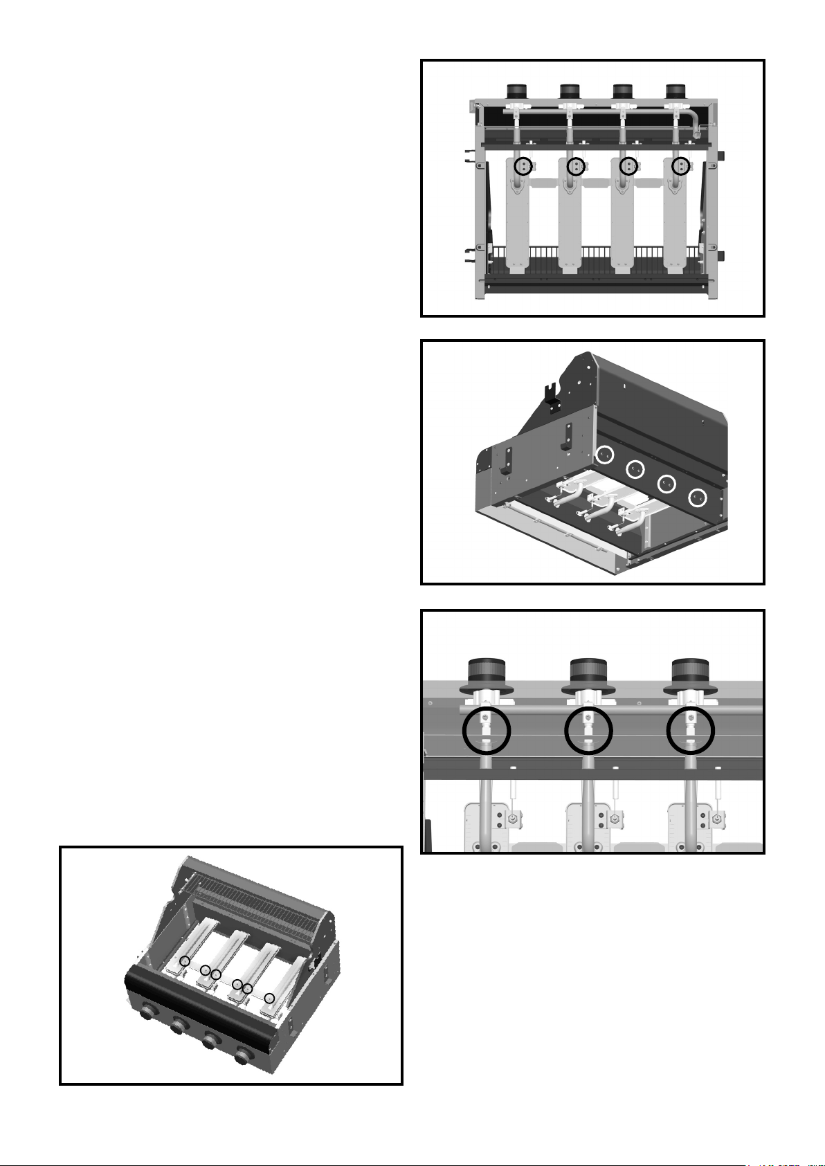
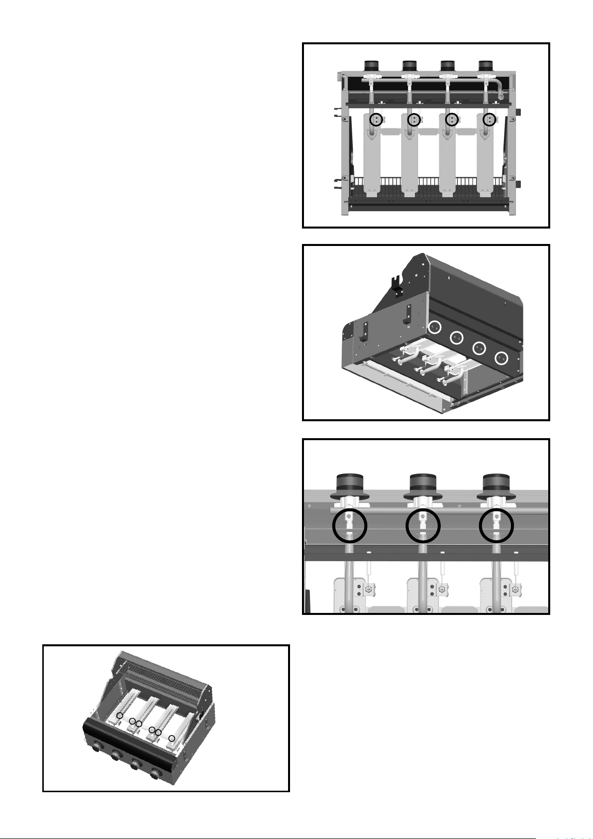
4. Remove the screws from the connection between
the burner and the ignition bracket on the
underside of the rebox. See Fig. B.
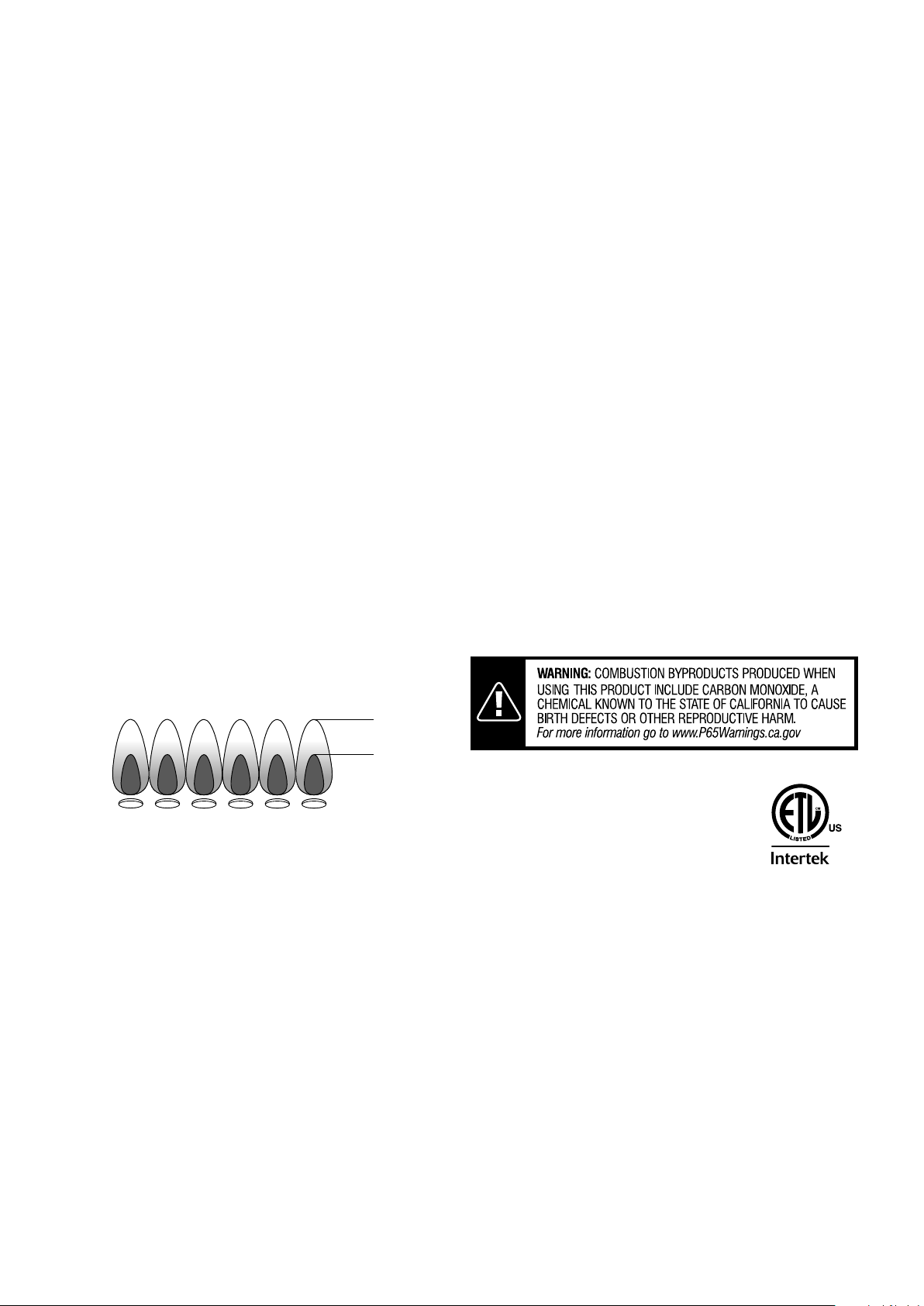
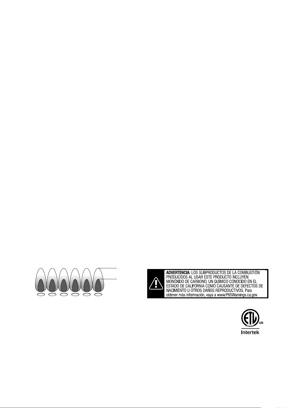
5. Remove the screws on the back board of the
rebox. See Fig. C.
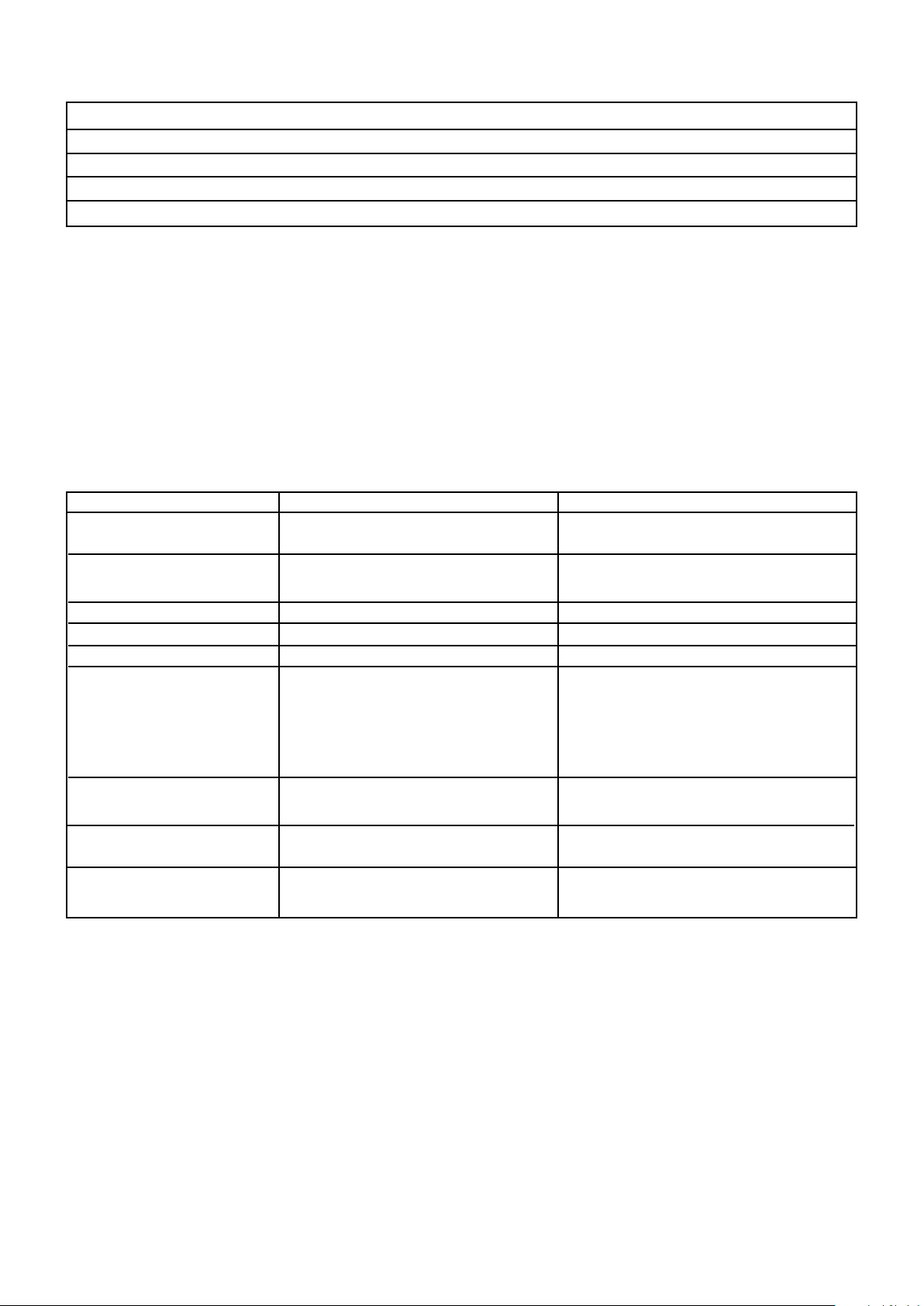
6. Fully remove the burner assembly from the
rebox.
We suggest the following ways to clean the burner
tubes. Use the one easiest for you.
(A) Using a narrow bottle brush or alloy wheel
brush with a exible handle (do not use a brass
wire brush), run the brush through each burner
tube several times.
(B) Wear eye protection: Use an air hose to force air
into the burner tube and out the burner ports.
Check each port to make sure air comes out
each hole.
27
Fig. A
Fig. B
Fig. C
Fig. D
6. Wire brush entire outer surface of burner to
remove food residue and dirt.
7. Clean any blocked ports with a sti wire such as
an open paper clip.
8. Check burner for damage, due to normal wear
and corrosion some holes may become enlarged.
If any large cracks or holes are found, replace
burner assembly.
9. Carefully re-install burner assembly.
VERY IMPORTANT: Burner tubes must reengage
valve openings. See Fig. D.
10. Secure burner assembly using the previously
removed screws from the back board of the
rebox (See Fig. C). Then t the previously
removed screws from the ignition bracket on the
underside of the rebox (See Fig. B). Finally, t
the previously removed screws from the ignition
plates connecting the burners (See Fig. A).
11. Replace vaporiser bars, cooking grills and
searing grill.
Burner Flame Check
• Remove cooking grill and vaporising bar. Light
burner, rotate knobs from HI to LO. You should
see a smaller ame in LO position than seen on
HI. Always check ame prior to each use.
Grease Tray
• IMPORTANT – Check and clean the grease tray
regularly before every use and replace if
necessary. Do not allow the fat residue to build
up in the tray.
• NEVER use without grease tray in position.
Fixings
• All screws and bolts, etc. should be checked and
tightened on a regular basis.
Storage
• Store your grill in a cool dry place.
• Cover the burner with aluminum foil in order to
prevent insects or other debris from collecting in
burner holes.
HIGH
LOW
• If the grill is to be stored indoors, the gas
bottle must be disconnected and left outside. The
gas bottle should always be stored outside, in a
dry, well-ventilated area, away from any sources
of heat or ignition.
• Disconnect the cylinder when the barbecue is not
in use.
• Do not let children tamper with the bottle.
• Cylinders must be stored outdoors out of reach of
children and must not be stored in a building,
garage or any other enclosed area.
DO NOT leave your grill uncovered when not in
use. Store your appliance in a shed or garage
when not in use to protect against the eects of
extreme weather conditions, particularly if you live
near coastal areas. Prolonged exposure to sunlight,
standing water, sea-air/saltwater can all cause
damage to your appliance. (A cover may not be
sucient to protect your appliance in some of these
situations)
• Accessible parts may be very hot. Keep young
children away.
• Always wear protective gloves when handling hot
components or items such as pots.
5010527
28
• To be performed in a well ventilated area.
• Conrm all control knobs are in the o position.
• Open the gas control valve on the bottle.
• Check for leaks by brushing a solution of 50% water and 50% dish soap over the gas system joints,
• to test for leaks at any time.
• If bubbles form over any of the joints, there is a leak.
• Turn o gas supply and retighten all joints.
• Repeat test. If bubbles form again, do not use the patio heater. Please contact the helpline stated in
• Leak test annually and whenever the gas bottle is removed or replaced.
• The gas hose must be connected in accordance with these instructions. When installed correctly all
part of hose should be outside of the Patio heater body where it could be a trip hazard or could be
• See instructions supplied with regulator for correct use and attachment.
• Gas bottles should never be stored on their side.
• Never store gas bottles indoors.
• This appliance is supplied with a propane regulator which must only be used for propane gas.
NEVER use an adjustable regulator with this appliance.
• Please consult your gas dealer for the most suitable gas bottles for your regulator.
• This appliance is for OUTDOOR USE ONLY and should be placed in a well ventilated area.
• A well ventilated area must have a minimum of 30% of its surface area open.
(Surface area is dened as the total surface of the walls surface.)
• The sides of the appliance should NEVER be closer than 40 inches (1m) from any combustible surface.
• Keep this appliance away from any ammable materials!
• Important - Make sure the gas bottle is placed level within the base.
• Should you need to change the gas bottle, conrm the gas supply is turned o at the regulator or
bottle / cylinder valve, and there are no sources of ignition (cigarettes, open ame, sparks, etc.) near
• Inspect the gas hose to ensure it is free from any twisting or tension. The hose should hang freely with
no bends, folds, or kinks that could obstruct free ow of gas. Always inspect the hose for cuts, cracks,
or excessive wear before use. If the hose is damaged, it must be replaced with hose suitable for use
• Conrm all control knobs are in the o position.
• Connect the regulator to the gas bottle according to your regulator and bottle dealers instructions.
WARNING:
FUELS USED IN LIQUEFIED PROPANE GAS
APPLIANCES, AND THE PRODUCTS OF COMBUSTION OF SUCH
FUELS, CAN EXPOSE YOU TO CHEMICALS INCLUDING BENZENE,
WHICH IS KNOWN TO THE STATE OF CALIFORNIA TO CAUSE
CANCER AND CAUSE BIRTH DEFECTS OR OTHER REPRODUCTIVE
HARM.
For more information go to: www.P65Warnings.ca.gov.
29
Grill Specications
Burner 4 Burner
Injector Size 1.0 MM
Gas/Pressure 11" per W.C
Input Rate 11,700 BTU/HR*3 (main) 14,000 BTU/HR*1 (searing)
Standard ANSI STD Z21.58-2018 Outdoor Cooking Gas Appliances
TECHNICAL AND SERVICING INFORMATION
This appliance is designed for outdoor use only using Propane gas at a supply pressure of 11" per WC
and must be serviced by a competent person in accordance with the instructions included. Please read all
accompanying documentation carefully.
TROUBLESHOOTING
Problem Possible Cause Solution
Burner will not light using LP gas cylinder is empty Replace with full cylinder
the ignition system
Faulty regulator Have regulator checked
or replace
Obstructions in burner Clean burner
Obstructions in gas jets or gas hose Clean jets and gas hose
Electrode wire is loose Reconnect wire
Electrode or wire is damaged Change electrode and wire
Low ame or ashback Obstructions in burner Clean burner
(re in burner tube - a
hissing or roaring noise may
be heard
Obstructions in gas jets or Clean jets and gas hose
gas hose
Windy conditions Use grill in a more
sheltered position
Gas valve knob dicult to Gas valve jammed Replace gas valve
turn

KENMORE LIMITED WARRANTY
WITH PROOF OF SALE, the following warranty coverage applies when this appliance is correctly installed, operated and
maintained according to all supplied instructions.
FOR ONE YEAR from the date of sale this appliance is warranted against defects in material or workmanship. A defective
appliance will receive free repair. If the appliance cannot be repaired it will be replaced free of charge.
FOR FIVE YEARS from the date of sale, any stainless steel burner that rusts through or burns through will be replaced free of
charge.* If rust through or burn through occurs within the rst year, a new burner will be installed at no charge. If rust through or
burn through occurs after the rst year, a new burner will be supplied but not installed at no charge. You are responsible for the
labor cost of burner installation after the rst year from the date of sale. *Rust-through or burn-through must be veried by a
Sears authorized service representative.
For warranty coverage details to obtain free repair or replacement, visit the web page: www.kenmore.com/warranty
All warranty coverage excludes ignitor batteries and grill part paint loss, discoloration or surface rusting, which are either
expendable parts that can wear out from normal use within the warranty period, or are conditions that can be the result of
normal use, accident or improper maintenance.
All warranty coverage is void if this appliance is ever used for other than private household purposes.
This warranty covers ONLY defects in material and workmanship, and will NOT pay for:
1. Expendable items that can wear out from normal use within the warranty period, including but not limited to batteries,
screw-in base light bulbs and surface coatings or nishes.
2. A service technician to clean or maintain this appliance, or to instruct the user in correct appliance installation, operation and
maintenance.
3. Service calls to correct appliance installation not performed by Sears authorized service agents, or to repair problems with
house fuses, circuit breakers, house wiring, and plumbing or gas supply systems resulting from such installation.
4. Damage to or failure of this appliance resulting from installation not performed by Sears authorized service agents, including
installation that was not in accord with electrical, gas or plumbing codes.
5. Damage to or failure of this appliance, including discoloration or surface rust, if it is not correctly operated and maintained
according to all supplied instructions.
6. Damage to or failure of this appliance, including discoloration or surface rust, resulting from accident, alteration, abuse, misuse
or use for other than its intended purpose.
7. Damage to or failure of this appliance, including discoloration or surface rust, caused by the use of detergents, cleaners,
chemicals or utensils other than those recommended in all instructions supplied with the product.
8. Damage to or failure of this appliance resulting from natural or other catastrophe, such as ood, re or storm.
9. Damage to or failure of parts or systems resulting from unauthorized modications made to this appliance.
10. Service to an appliance if the model and serial plate is missing, altered, or cannot easily be determined to have the
appropriate certication logo.
Disclaimer of implied warranties; limitation of remedies
Customer’s sole and exclusive remedy under this limited warranty shall be product repair or replacement as provided herein.
Implied warranties, including warranties of merchantability or tness for a particular purpose, are limited to one year on
the appliance and ve years on the burners, or the shortest period allowed by law. Seller shall not be liable for incidental
or consequential damages. Some states and provinces do not allow the exclusion or limitation of incidental or consequential
damages, or limitation on the duration of implied warranties of merchantability or tness, so these exclusions or limitations may
not apply to you.
This warranty applies only while this appliance is used in the United States.
This warranty gives you specic legal rights, and you may also have other rights which vary from state to state.
Sears Brands Management Corporation, Homan Estates, IL 60179
30
Estas instrucciones son para su seguridad. Léalas cuidadosamente antes
de utilizar el equipo y guárdelas para futuras referencias.
ADVERTENCIA:
No almacene ni utilice gasolina u otros
vapores y líquidos inamables cerca de
este u otro artefacto. Si el cilindro de
gas propano líquido no se encuentra
conectado para su uso, no debe estar
guardado cerca de otro artefacto.
ADVERTENCIA:
¡Solo para uso en exteriores!
ADVERTENCIA:
Toda instalación, ajustes, modicaciones,
reparaciones o mantenimiento realizado
de forma incorrecta al equipo pueden
causar lesiones o daños materiales.
Lea cuidadosamente las instrucciones
de instalación, funcionamiento y
mantenimiento antes de instalar o
empezar a utilizar el equipo.
31
Tabla de contenidos
Piezas provistas 32
Equipo y antes de empezar 33
Diagrama y lista de piezas 34
Pasos del ensamblaje 35
Prueba de fugas 51
Instrucciones de seguridad 52
Instrucciones de uso 53
Cuidado y mantenimiento 54
Especicaciones y solución de
problemas de la parrilla 57
Garantía 58
Número de atención al cliente Contraportada
PELIGRO:
Si siente olor a gas:
1. Cierre la válvula de gas del equipo.
2. Apague cualquier llama visible.
3. Abra la tapa del equipo.
4. Si el olor continúa, aléjese del
artefacto y contacte inmediatamente
a su proveedor de gas o al
departamento de bomberos.
32
Ref. Descripción Ilustración Cantidad Ref. Descripción Ilustración Cantidad
Piezas provistas
10
11
12
13
14
15
16
17
18
19
20
1
4
3
1
1
1
1
1
2
1
2
Estante
Lateral
Plegable
Barra de
vapor
Parrilla para
Cocinar
Parrilla de
Cocción a la
Brasa
Rejilla para
calentar
Bandeja de
grasa
Soporte del
recipiente
colector de
grasa
Recipiente
colector de
grasa
Soporte de
rueda del
carro
Marco
izquierdo del
carro
Rueda del
carro
1
2
3
4
5
6
7
8
9
1
1
2
1
1
1
2
1
1
Base del
armario
Pared
izquierda +
Pared
derecha
Placa de
soporte del
armario
Panel frontal
del armario
Barra
transversal
Ensamblaje
del eje
Traba de
la Rueda
Pivotante
Soportes del
cilindro
Cámara de
combustión
33
Ref. Descripción Ilustración Cantidad Ref. Descripción Ilustración Cantidad
Piezas provistas
21
22
23
24
25
26
27
Marco
derecho del
carro
Estante del
carro
Riel del
carro
Mango del
Carro Lateral
Mesada del
carro
Contenedor
de basura
Tabla para
cortar
1
2
2
1
1
1
1
Componentes suministrados
A
B
C
Las piezas del equipo no se muestran en
tamaño real.
Antes de comenzar
Revise el contenido de la caja y asegúrese de
que cuenta con todas las piezas y partes arriba
enumeradas. De no ser así, contáctenos al 1-844-
553-6667.
Cuando esté listo para comenzar, asegúrese
de que tiene todas las herramientas a mano y
de contar con un espacio limpio y seco para
proceder con el ensamblaje.
Ensamblaje
Prepare las tuercas y pernos, y revise todas
las medidas antes de empezar a ensamblar.
Se recomienda cortar el cartón de la caja y
disponerlo en el suelo, para que sea utilizado
como soporte protector durante el ensamblaje.
Revisar los diagramas de ensamblaje cada vez
que sea necesario.
PRECAUCIÓN: Si bien se han tomado todas
las precauciones durante la fabricación de
este producto, se debe tener cuidado durante
el ensamblaje en caso de que haya bordes
alados.
Perno
M6 x 12
Perno
M4 x 10
Perno
M6 x 45
74
4
8
Diagrama
34
Piezas provistas
Clave Descripción Cantidad Número
de pieza
Tapa
Medidor de temperatura
Logo
Bisel del mango de la tapa
Mango de la tapa
Cámara de combustión
Varilla giratoria
Soporte del estante posterior izquierdo
Soporte del estante frontal izquierdo
Soporte del estante posterior derecho
Soporte del estante frontal derecho
Abridor de garrafa
Dial de control del bisel
A01
A02
A03
A04
A05
A06
A07
A08
A09
A10
A11
A12
A13
1
1
1
2
1
1
2
1
1
1
1
1
4
Dial de control
Bandeja de grasa
Soporte del recipiente colector de grasa
Recipiente colector de grasa
Rejilla para calentar
Parrilla para Cocinar
Parrilla de Cocción a la Brasa
Barra de vapor
Quemador
Válvula de Gas
Colector
Manguera de gas
Regulador
A14
A15
A16
A17
A18
A19
A20
A21
A22
A23
A24
A25
A26
4
1
1
1
1
3
1
4
4
4
1
1
1
506 A01
506 A02
506 A03
506 A04
506 A05
506 A06
506 A07
506 A08
506 A09
506 A10
506 A11
506 A12
506 A13
506 A14
506 A15
506 A16
506 A17
506 A18
506 A19
506 A20
506 A21
506 A22
506 A23
506 A24
506 A25
506 A26
A01
A02
A03
A04
A05
A06
A07
A08
A09
A12
A13
A14
A15
A16
A17
A10
A11
A18
A19
A20
A21
A22
A23
A24
A25
A26
Clave Descripción Cantidad Número
de pieza

Ensamblaje – Paso 1
35
Coloque la pared izquierda y la pared derecha en la base del armario (como se muestra abajo), utilizando
8 de los pernos M6 x 12.
Nota: La pared derecha tiene un oricio en la esquina superior.
Esta es una vista desde la parte posterior.
Base del armario
Perno M6 x 12
Pared izquierda + Pared
derecha
Pared derecha Pared izquierda
Perno M6 x 12

Ensamblaje – Paso 2
36
Coloque las 2 placas de soporte del armario con el ensamblaje de la base y las paredes, utilizando 8 de
los pernos M6 x 12, como se muestra abajo.
Placa de soporte del
armario (x2)
Perno M6 x 12
Placa de soporte del
armario
Perno M6 x 12

Ensamblaje – Paso 3
37
Note: Dé vuelta el ensamblaje del armario, de modo que la pared izquierda mire al suelo.
Junte el panel frontal del armario con las paredes laterales montadas, como se muestra abajo, utilizando 6
de los pernos M6 x 12.
Nota: Requerirá la asistencia de otra persona para mantener la puerta en posición mientras ajusta los
pernos.
Panel frontal del
armario
Panel frontal del
armario
Perno M6 x 12

Ensamblaje – Paso 4
38
Coloque la barra transversal utilizando 4 de los pernos M4x10.
Asegure la cadena de la barra transversal a la puerta del panel frontal utilizando el perno M6 x 12 y la
arandela preinstalados.
Pernos M4 x 10
Barra transversal
Barra
transversal
Ensamblaje – Paso 5
Dé vuelta el ensamblaje del armario y coloque el ensamblaje del eje y dos ruedas pivotantes en la parte
inferior de la base del armario, utilizando 16 de los pernos M6 x 12.
Nota: El lado del eje que lleva la abertura va en la parte trasera del carro.
Nota: Una vez que el equipo esté ensamblado y colocado en posición, baje las palancas de las ruedas
pivotantes para que estas queden trabadas. Procure siempre desprender el carro lateral de la parrilla
cuando traslade el equipo.
Ensamblaje del eje Traba de la Rueda
Pivotante (x2)
Ensamblaje del eje
Traba de la Rueda
Pivotante
Base del armario
Perno M6 x 12
39

Ensamblaje – Paso 6
40
Dé vuelta el ensamblaje del armario. Coloque dos soportes del cilindro en la base del armario utilizando 6
de los pernos M6 x 12.
Soportes del cilindro
Soporte del
cilindro
Perno M6 x 12
Ensamblaje – Paso 7
41
Cámara de combustión
Proceda a cortar los precintos que sujetan el regulador y la manguera a la parte inferior de la cámara de
combustión. Deje la manguera suelta para colocar la cámara de combustión en la parte inferior del carro.
Coloque la cámara de combustión sobre el armario. Abra la cubierta y utilice 4 de los pernos M6 x 12 para
jar la cámara de combustión en la posición indicada.
Asegúrese de que los bordes de la cámara de combustión están alineados con los ejes del carro, antes de
comenzar a ajustar los pernos.
Nota: Los oricios de jación están ubicados en el interior de la cámara de combustión (2 de cada lado).
Nota: Se necesita de dos personas para levantar la cámara de combustión y colocarla en la posición
indicada.
Perno M6 x 12
Pasador R y
barra de metal
Barra larga
Ensamblaje – Paso 8
42
Estante Lateral Plegable
Quite los pasadores R preinstalados y barras de metal de los soportes laterales de la cámara de
combustión.
Coloque los soportes del armario sobre los soportes de la cámara de combustión. Procure que todos los
oricios estén alineados. Reinserte los pasadores R y las barras de metal para asegurar el estante.
Para que el estante esté listo para su uso,
levántelo y sosténgalo contra el costado de
la cámara de combustión con una mano.
Pase la otra mano por debajo del estante
para levantar la barra larga, e insértela en
los ganchos soporte de la cámara de
combustión. Para plegar el estante hacia
abajo, pase nuevamente una mano por
debajo del estante, retire la barra larga, y
con cuidado proceda a hacer bajar el
estante con la otra mano.
Rejilla para calentar
Ensamblaje – Paso 9
43
1. Coloque las barras de vapor (x4) en la posición indicada.
2. Coloque las parrillas para cocinar (son 3) y la parrilla de cocción a la brasa en la posición que se indica.
3. Coloque la rejilla para calentar en la posición indicada.
Nota: Como accesorio útil, hay un abridor de botellas en el costado izquierdo de la cámara de combustión.
1.
2.
3.
Barra de vapor (x4) Parrilla para
Cocinar (x3)
Parrilla de Cocción a la
Brasa
Rejilla para calentar
Nota: La Parrilla de Cocción a la Brasa
debe ser colocada sobre el Quemador
de Cocción a la Brasa. Para una cocción
optima, dicho Quemador (14000 BTU)
alcanza una mayor temperatura que
los otros tres quemadores (11700 BTU).
El diseño de rombos de la Parrilla de
Cocción a la Brasa se diferencia del
diseño de las otras tres parrillas ya
que, gracias a los rombos, las brasas
penetran la supercie de la carne para
una cocción ideal.
Ensamblaje – Paso 10
44
Fije el recipiente colector de grasa a la bandeja de grasa utilizando uno de los pernos M6 x 12, y luego
deslice la bandeja por la parte posterior de la parrilla, como se muestra a continuación. Abra la puerta del
panel frontal y coloque el recipiente colector de grasa sobre el soporte instalado para dicho recipiente.
Nota: Para poder quitar el recipiente colector de grasa para su limpieza, baje la puerta del panel frontal.
Adicionalmente, como accesorio útil, hay tres huecos para apoyar bebidas en el lado interno de la puerta.
Bandeja de grasa
Soporte del recipiente
colector de grasa
Bandeja de grasa
Soporte del recipiente
colector de grasa
Recipiente colector
de grasa
Recipiente colector
de grasa
Perno M6 x 12

Ensamblaje – Paso 11
45
Rueda del carro (x2)Soporte de rueda del
carro (x2)
Marco izquierdo del
carro
Perno M6 x 12
1. Coloque los soportes de las ruedas en el marco izquierdo, como se indica abajo, utilizando 8 de los
pernos M6 x 12.
2. Coloque las 2 ruedas en los soportes utilizando los pernos y arandelas que están preinstalados y unidos a
las ruedas.

Ensamblaje – Paso 12
46
Apoye el marco izquierdo del carro en el suelo y empiece montando el estante del medio, utilizando 2 de
los pernos M6 x 12. Luego, coloque el estante inferior, utilizando 3 de los pernos M6 x 12. A continuación,
junte el marco derecho del carro con los estantes montados utilizando 5 de los pernos M6 x 12.
Nota: Hay 3 opciones de altura para los estantes.
Nota: Los oricios para los pernos
están ubicados debajo de los estantes
del carro.
Marco derecho del
carro
Estantes del carro
(x2)
Pernos M6 x 12

Ensamblaje – Paso 13
47
Coloque los dos rieles en el marco del carro, como se indica, utilizando 8 de los pernos M6 x 45.
Nota: Procure que, cuando je los rieles del carro, el lado ancho de estos mire hacia arriba.
Riel del carro (x2)
Fije el mango del carro lateral a la parte
superior del marco derecho del carro
utilizando 2 Pernos M6 x 12.
Mango del Carro Lateral Perno M6 x 45
Perno M6 x 12

Ensamblaje – Paso 14
48
Coloque la mesada en el marco utilizando 5 de los pernos M6 x 12.
Mesada del carro Contenedor de
basura
Tabla para cortar
Coloque el contenedor de basura y la tabla para cortar
dentro de la mesada, como se indica.
Perno M6 x 12
49
Ensamblaje – Paso 15
Para ajustar el carro al cuerpo de la parrilla, levántelo ligeramente por el lado izquierdo y bájelo para
encajarlo en los soportes laterales de la parrilla. Nota: Asegúrese de que las ruedas del carro miren hacia
la izquierda. Si preere continuar utilizando el carro por separado, puede quitar los soportes laterales de la
parrilla.
Nota: Procure siempre desprender el carro lateral de la parrilla cuando traslade el equipo.
Coloque el cilindro de gas dentro del armario por la parte posterior. Colóquelo entre los soportes y
asegúrelo con las cadenas, enganchándolo a los extremos de estas.
Conecte el cilindro de gas al regulador como se indica. Efectúe la prueba de fugas (ver página 23).
Utilice el panel frontal del armario para acceder fácilmente a la manguera de gas y al regulador.
Nota: El recipiente colector de grasa debe estar colocado en el lado opuesto al cilindro de gas.
Atornille el regulador
al cilindro de gas.
Cuando conecte la manguera exible, asegúrese de que no se encuentre
torcida.
Utilice un cilindro de gas propano líquido, con una altura máxima de 17,75
pulgadas, un grosor máximo de 12,25 pulgadas y un peso máximo 20 libras.
12.25"
17.75"
Ensamblaje - Paso 16
Cilindro de
gas
Soportes
del cilindro
Cadena
Regulador
50
Ensamblaje – Paso 17
Prueba de fugas
Para descartar fugas, se han efectuado todas las
revisiones de fábrica sobre las conexiones del
equipo. Le rogamos que efectúe la prueba de fugas
en un lugar ventilado. Asegúrese de que todos los
botones del equipo se encuentren apagados. Para
revisar los puntos de conexión manguera de gas/
regulador y regulador/cilindro, usted debe:
1. Preparar una mezcla con agua (50%) y jabón
líquido para platos (50%), para su utilización en
la prueba.
2. Verter varias gotas de la solución sobre un cepillo.
Cepillar los puntos de conexión manguera de
gas/regulador y regulador/cilindro, así como
también la conexión de la manguera.
3. Encienda la válvula del cilindro de gas.
Observe los puntos de conexión y revise si hay
burbujas.
NUNCA UTILIZAR UNA LLAMA EXPUESTA para
efectuar la prueba de fugas.
4. Si no se observan burbujas, las conexiones son
seguras.
5. Si se observan burbujas, se está produciendo una
fuga.
Proceda a apagar el gas y ajuste nuevamente todas
las conexiones.
Repita la prueba. Si aparecen burbujas nuevamente,
no utilice el equipo. Proceda a contactarse con la
línea de asistencia indicada en este manual.
Las pruebas de fuga deben realizarse anualmente y
siempre que se quite o se cambie el cilindro de gas.
NOTA: La prueba de fugas debe llevarse a cabo antes de
empezar a utilizar el aparato.
Manguera / Regulador Regulador / Cilindro
Puntos de conexión donde debe efectuarse la prueba
51

INSTRUCCIONES DE SEGURIDAD
Advertencias
• El no leer y seguir estas instrucciones puede causar
lesiones graves o daños materiales.
• Este producto es para USO EXTERIOR
SOLAMENTE.
• Este producto no debe usarse en un edicio, garaje
o cualquier otra área cerrada.
• Esta parrilla a gas para exterior no está diseñada
para ser instalada en barcos.
• Este producto no debe instalarse en vehículos
recreativos.
• Posicionamiento: asegúrese de que la unidad esté
a un mínimo de 40 pulgadas (1 m) de elementos
o estructuras inamables desde todos los lados y
desde arriba.
• Este producto no debe utilizarse en construcciones
elevadas inamables.
• Coloque siempre el cilindro de gas como se indica
en este manual; mantenga siempre el cilindro en
posición vertical.
• Importante: asegúrese de que la parrilla esté
colocada en una supercie plana y nivelada para
ayudar a que la grasa se corra.
• Importante: REALICE UNA PRUEBA DE FUGAS EN
LA PARRILLA CUANDO ESTÉ COMPLETAMENTE
MONTADA ANTES DEL PRIMER USO. ADEMÁS,
debe realizar una prueba de fugas de la unidad
anualmente, cuando se desmonte, cuando se
reemplacen las piezas o si se retira o reemplaza el
cilindro de gas. NO HACER ESTE PODRÍA CAUSAR
LESIONES GRAVES O DAÑOS A LA PARRILLA.
• Asegúrese siempre de que el cambio del cilindro
de gas se realice lejos de cualquier fuente de
ignición.
• No obstruya el ujo de aire de combustión y
ventilación.
• NUNCA la use en interiores, en un área cerrada o
por debajo del nivel del suelo.
• Se debe utilizar el regulador de presión y la
manguera suministrados con la parrilla a gas para
exterior. Cualquier repuesto del regulador
de presión y de la manguera deben ser los
especicados por el fabricante de la parrilla a gas
para exterior.
El cilindro de gas propano líquido que se utilice
debe cumplir con las siguientes características:
a. Construidos y marcados de acuerdo con las
especicaciones de los cilindros de gas líquido
propano del Departamento de Transporte de EE.UU.
(D.O.T.), CAN/CSA-B339, o según la
52
Norma en materia de cilindros, esferas y tubos
para el transporte de mercancías peligrosas, según
corresponda; y
b. Provisto de un dispositivo de prevención de
sobrellenado; y
c. Provisto de un dispositivo de conexión de cilindro
compatible con la conexión para equipos de
cocción para exterior.
• El cilindro utilizado debe incluir un collar para
proteger la válvula de este.
• No almacene cilindros de gas propano líquido
de repuesto debajo o cerca de este aparato.
Nunca llene el cilindro por encima del 80% de su
capacidad. Si no se sigue la información anterior
con exactitud, puede provocar un incendio con
peligro de muerte o lesiones graves.
• Se pueden utilizar otros cilindros con este equipo
siempre que sean compatibles con los medios de
retención del aparato.
• Coloque la tapa antipolvo en la salida de la
válvula del cilindro siempre que este no esté siendo
utilizado. Debe instalar únicamente el tipo de tapa
antipolvo en la salida de la válvula del cilindro
proporcionada con la válvula del cilindro. Otros
tipos de tapas o tapones pueden provocar fugas
de propano.
• Este equipo ha sido suministrado con un
REGULADOR DE GAS PROPANO LÍQUIDO
(utilizar únicamente con gas propano líquido).
• NUNCA use un regulador ajustable con esta
parrilla.
• Este producto tomará temperatura cuando esté en
uso; tenga cuidado al tocarlo.
• Mantenga a los niños y mascotas a una distancia
segura de la unidad cuando esta esté en uso.
• NO mueva este producto cuando esté en uso.
• Siempre apague el suministro de gas en el cilindro
de gas cuando este no esté en uso.
• Cualquier modicación de esta parrilla puede ser
peligrosa.
• NO deje este producto desatendido cuando esté
en uso.
• Las partes selladas por el fabricante o su
representante no deben ser alteradas por el
usuario.
• Al encender, siempre mantenga la tapa abierta.
• SOLO utilice la parrilla en una supercie o suelo
plano o no inamable NIVELADO.
• Esta parrilla no está diseñada para ser utilizada
con carbón u otro combustible similar.
53
• NO utilice gasolina, aguarrás, líquido inamable,
alcohol u otros productos químicos similares para
encender la parrilla.
• Cuando almacene la parrilla o el cilindro de gas,
asegúrese de que estén alejados de materiales o
líquidos inamables.
• Siga siempre las instrucciones de cuidado y
mantenimiento; realice un mantenimiento regular a
su parrilla.
• NO permita que se acumule grasa o residuos
de alimentos en o sobre la parrilla - RIESGO DE
INCENDIO.
• Siempre reemplace las piezas desgastadas: no
utilice la parrilla si encuentra una fuga, desgaste o
daños.
• Nunca sobrecargue la parrilla con alimentos:
distribúyalos de manera uniforme sobre la
supercie de cocción para asegurar la circulación
de aire suciente en los quemadores.
• NO almacene ni cubra la parrilla hasta que esté
completamente enfriada.
• Mantenga el área de la parrilla a gas para
exterior limpia y libre de materiales combustibles,
gasolina y otros vapores y líquidos inamables.
• No vacíe la bandeja de grasa hasta que la parrilla
se haya enfriado.
• Este producto no es adecuado para utilizarlo con
carbón.
• Conserve las instrucciones para futuras referencias.
• La instalación debe cumplir con los códigos
locales o, en ausencia de códigos locales, con
el Código Nacional de Gas Combustible, ANSI
Z223.1/NFPA 54, el Código de Instalación de Gas
Natural y Propano. CSA B149.1, o con el Código de
Almacenamiento y Manejo de Propano, B149.2
A PESAR DE QUE SE HAN TOMADO TODAS LAS
PRECAUCIONES PARA ELIMINAR LOS BORDES
AFILADOS, SIEMPRE TENGA CUIDADO AL
MANIPULAR LOS COMPONENTES DE METAL.
No devuelva los productos a la tienda donde
efectuó la compra.
INSTRUCCIONES DE USO
Conectar el cilindro
• Conrme que todas las perillas del control y que el
gas estén en la posición de apagado.
• Conecte el regulador a la garrafa de gas de
acuerdo con las instrucciones del regulador y del
distribuidor de garrafas.
Instrucciones de uso - Parrilla
Antes de continuar, asegúrese de comprender la
sección de ADVERTENCIAS de este manual.
• Preparación antes de cocinar: para evitar que los
alimentos se adhieran a la supercie de cocción,
aplique una capa ligera de aceite de cocina o
vegetal a los alimentos antes de comenzar con la
barbacoa.
• Nota: Al cocinar por primera vez, los colores de la
pintura pueden cambiar ligeramente como
resultado de las altas temperaturas. Esto es normal
y está previsto que suceda.
• Inspeccione la manguera antes de cada uso de la
parrilla a gas para exterior.
• Si es evidente que hay una abrasión o desgaste
excesivos, o si la manguera presenta un corte,
esta debe reemplazarse antes de poner en
funcionamiento la parrilla a gas para exterior.
El repuesto de la manguera debe ser idéntico a la
pieza original. Ver la lista de piezas.
Encender la Parrilla
• Encienda el suministro de gas en el cilindro de gas.
• Presione el dial de control y gire lentamente a la
posición .
• Si el quemador no se enciende, vuelva a la
posición e intente nuevamente.
• Una vez que se haya producido el encendido,
mantenga presionado el botón durante al menos
10 segundos para asegurarse de que el quemador
permanezca encendido.
• Si el quemador no se enciende o no permanece
encendido después de mantener presionado el dial
durante 10 segundos, gire el dial a la posición
espere 1 minuto e intente nuevamente. No sostenga
el dial continuamente ya que puede causar una
acumulación de gas.
• En condiciones de viento, debe proteger la parrilla
del viento para garantizar un encendido fácil.
• Gire el dial de control para modicar la
conguración del quemador según sea necesario.
Para apagarla:
• Empuje el dial hacia adentro y gire a la posición
• Apague el gas y desconecte el cilindro cuando no
esté en uso.
Instrucciones de uso - Carro lateral
El cliente tiene la opción de jar el carro lateral
a la parrilla o mantenerlo separado. Para jar
el carro lateral a la parrilla, levante el carro
lateral ligeramente a la izquierda y bájelo para
asegurarlo en los soportes laterales de la parrilla.
Nota: asegúrese de que las ruedas laterales del
carro estén en el lado izquierdo. Si desea mantener
el carro lateral por separado, puede quitar los
soportes laterales de la parrilla.

54
Instrucciones de encendido manual
• Retire la parrilla de cocción a la brasa y la barra
de vapor de la barbacoa.
• Coloque una cerilla encendida al lado del
quemador (en el mismo lugar que el encendedor)
• Presione y gire la perilla de control lo más a la
derecha posible en el sentido contrario a las
agujas del reloj, hasta la posición alta.
• Después de un encendido exitoso, encienda cada
quemador de izquierda a derecha según lo desee.
• Si el quemador no se enciende después de
repetidos intentos, comuníquese con el número de
Servicio al Cliente que se indica en este manual.
ADVERTENCIA
• Si huele gas, apague la parrilla, extinga todas
las llamas y abra la cubierta de la parrilla. Si el
olor continúa, comuníquese inmediatamente con su
proveedor de gas.
• En el caso de un incendio incontrolable,
desconecte inmediatamente el cilindro de gas,
aléjelo del fuego y póngase en contacto con el
departamento de bomberos. ¡NO SE PONGA EN
RIESGO!
• Asegúrese de que no se utilicen aerosoles cerca de
este equipo cuando esté en uso.
• Asegúrese de que todo el embalaje y las bolsas de
plástico se desechen de forma segura.
Cocinar en la parrilla
La Barra de Vapor distribuye uniformemente el
calor en el área de cocción de la parrilla. Los
jugos naturales producidos durante la cocción caen
sobre la barra de vapor caliente que se encuentra
debajo y se vaporizan. La cocción pareja de los
alimentos se logrará utilizando la parrilla con la
cubierta hacia abajo. Esto solo debe hacerse con el
quemador en posición baja.
Control de llamarada
IMPORTANTE: PUEDEN OCASIONARSE
LLAMARADAS POR LOS RESIDUOS DE GRASA Y
JUGOS ENTRE LOS QUEMADORES Y LA BARRA
DE VAPOR CALIENTE. Para disminuir esto, limpie
regularmente los quemadores y la barra de vapor.
Para controlar las llamaradas, es aconsejable
eliminar el exceso de grasa de la carne antes de
asarla. Los quemadores siempre deben colocarse
en la posición baja durante la cocción. Siempre
protéjase las manos cuando manipule algo cerca de
la supercie de cocción de la parrilla.
Finalizar la cocción
Después de cada sesión de cocción, gire los
quemadores de la parrilla a la posición y
déjelos así durante 5 minutos. Este procedimiento
quemará los residuos de cocción y facilitará la
limpieza.
Cuidado y Mantenimiento
• Limpie regularmente su parrilla entre cada uso
y especialmente después de largos períodos de
almacenamiento.
• Asegúrese de que la parrilla y sus componentes
estén lo sucientemente fríos antes de limpiarlos.
• No deje la parrilla expuesta a condiciones
climáticas exteriores y tampoco debe guardarla en
áreas húmedas.
• Nunca apague la parrilla con agua cuando las
supercies estén calientes.
• Nunca manipule las partes calientes con las manos
desprotegidas.
• Para prolongar la vida útil y mantener el estado
de su parrilla, recomendamos encarecidamente
que la unidad esté cubierta cuando se deja afuera
por un período prolongado, especialmente durante
los meses de invierno.
• IMPORTANTE: Recomendamos que el servicio
técnico de este aparato se realice cada 100 horas
de uso o anualmente, según corresponda.
• Cambie el tubo exible cuando las condiciones
nacionales lo requieran.
• Mantenga el área de la parrilla a gas para
exterior limpia y libre de materiales combustibles,
gasolina y otros vapores y líquidos inamables.
Parrilla
• Limpiar con agua caliente con jabón.
• Para eliminar cualquier residuo de comida, use
un limpiador en crema suave sobre un paño no
abrasivo.
• Enjuague y seque bien.
Cuerpo de la Parrilla
• Elimine regularmente el exceso de grasa del
cuerpo de la parrilla con un raspador de madera o
de plástico suave.
• No es necesario quitar toda la grasa del cuerpo.
Si necesita limpiarla por completo, utilice
solamente agua caliente con jabón y un paño, o un
cepillo de cerdas de nailon.
• Retire las supercies de cocción y los quemadores
antes de limpiarlos por completo.
• No sumerja los controles de gas o el colector en
agua.
• Verique el funcionamiento del quemador después
de volver a colocarlo cuidadosamente en el
cuerpo.
Mantenimiento del quemador
• Con un uso normal, quemar los residuos después
de la cocción mantendrá los quemadores limpios.
Sugerimos las siguientes formas de limpiar los tubos
del quemador. Siga la que sea más fácil para usted.
(A) Con un cepillo para botella estrecho o un cepillo
de aleación con un mango exible (no utilice un
cepillo de alambre de latón), pase el cepillo por
cada tubo del quemador varias veces.
(B) Utilice protección para los ojos: Utilice una
manguera de aire para forzar el aire dentro del
tubo del quemador y hacer que salga por las
cavidades del quemador. Revise cada cavidad para
asegurarse de que salga aire por cada oricio.
55
Fig. A
Fig. B
Fig. C
Fig. D
• Los quemadores deben limpiarse anualmente, o
siempre que haya una acumulación pesada, para
asegurarse de que no haya signos de obstrucción
(restos, insectos) en los oricios del quemador o en
los tubos de venturi de los quemadores instalados
sobre las salidas de la válvula. Un tubo obstruido
puede provocar un incendio debajo de la parrilla.
Barra de vapor
• Limpie la barra de vapor con jabón y agua tibia
con un paño o esponja de limpieza poco
abrasivos.
PRECAUCIÓN: ¡ALERTA DE ARAÑAS! Las arañas o
pequeños insectos pueden provocar un retroceso de
llamas. Las arañas forman su telaraña o construyen
nidos en los tubos del quemador de la parrilla,
y obstruyen el ujo de gas al quemador. El gas
acumulado puede encenderse en el tubo detrás del
panel de control. Esto se conoce como retroceso
y puede dañar su parrilla o causar lesiones
físicas. Para evitar el retroceso y asegurar un buen
rendimiento, retire y limpie los quemadores antes de
usarlos siempre que la parrilla haya estado inactiva
durante un período prolongado.
Limpieza del ensamblaje del quemador
Siga estas instrucciones para limpiar y/o
reemplazar el ensamblaje del quemador o si tiene
problemas para encender la parrilla.
1. Apague el gas en las perillas de control y en el
cilindro de gas propano líquido.
2. Retire las parrillas para cocinar, la parrilla de
cocción a la brasa y las barras de vapor.
3. Retire los pernos de las placas de encendido
que conectan los quemadores. Vea la gura A a
continuación.
4. Retire los pernos de la conexión entre el
quemador y el soporte de encendido en la parte
inferior de la cámara de combustión. Ver Fig. B.
5. Retire los pernos de la placa posterior de la
cámara de combustión. Ver Fig. C.
6. Retire por completo el ensamblaje del quemador
de la cámara de combustión.
6. Pase un cepillo de alambre en toda la supercie
exterior del quemador para eliminar los residuos
de alimentos y la suciedad.
7. Limpie las cavidades bloqueadas con un cable
rígido, como un clip de papel desplegado.
8. Revise el quemador para ver si está dañado.
Debido al desgaste normal y la corrosión, algunos
oricios pueden agrandarse. Si encuentra grietas
u oricios grandes, reemplace el ensamblaje del
quemador.
9. Vuelva a instalar con cuidado el ensamblaje del
quemador.
MUY IMPORTANTE: los tubos del quemador deben
volver a conectar las aberturas de las válvulas. Ver
Fig. D.
10. Asegure el ensamblaje del quemador utilizando
los pernos que retiró anteriormente de la placa
posterior de la cámara de combustión (ver
Fig. C). Luego, coloque los pernos que retiró
anteriormente del soporte de encendido en la
parte inferior de la cámara de combustión (ver
Fig. B). Finalmente, instale los pernos que retiró
previamente de las placas de encendido que
conectan los quemadores (ver Fig. A).
11. Vuelva a colocar las barras de vapor, las
parrillas para cocinar y la parrilla de cocción a
la brasa.
Control de llama del quemador
• Retire la parrilla de cocción y la barra de vapor.
Encienda el quemador, gire las perillas de HI (alto)
a LO (bajo). Debería ver una llama más pequeña
en la posición LO que en HI. Siempre revise la
llama antes de cada uso.
Bandeja de grasa
• IMPORTANTE – Revise y limpie la bandeja
de grasa regularmente antes de cada uso y
reemplácela si es necesario. No permita que los
residuos de grasa se acumulen en la bandeja.
• NUNCA utilice el equipo sin la bandeja de grasa
en la posición correspondiente.
Fijaciones
• Todos los pernos y pernos, etc. deben revisarse y
ajustarse regularmente.
ALTO
BAJO
Almacenamiento
• Guarde su parrilla en un lugar fresco y seco.
• Cubra el quemador con papel de aluminio para
evitar que insectos o residuos se acumulen en los
oricios del quemador.
• Si va a almacenar la parrilla en un espacio
interior, debe desconectar la garrafa de gas y
dejarla afuera. La garrafa de gas siempre debe
almacenarse afuera, en un área seca y bien
ventilada, lejos de cualquier fuente de calor o
ignición.
• Desconecte el cilindro cuando la barbacoa no esté
en uso.
• No permita que los niños manipulen la garrada.
• Los cilindros deben almacenarse al aire libre fuera
del alcance de los niños y no deben almacenarse
en un edicio, garaje o cualquier otra área
cerrada.
NO deje su parrilla descubierta cuando no esté
en uso. Guarde el equipo en un cobertizo o garaje
cuando no esté en uso para protegerlo de los
efectos de las condiciones climáticas extremas,
especialmente si vive cerca de una zona costera.
La exposición prolongada a la luz solar, el agua
estancada, el aire de mar/agua salada pueden
causar daños a su parrilla. (Es posible que una
cubierta no sea suciente para proteger su equipo
en algunas de estas situaciones)
• Las partes accesibles pueden estar muy calientes.
Mantenga a los niños pequeños alejados.
• Siempre use guantes protectores cuando manipule
componentes calientes u objetos tales como ollas.
5010527
56
• To be performed in a well ventilated area.
• Conrm all control knobs are in the o position.
• Open the gas control valve on the bottle.
• Check for leaks by brushing a solution of 50% water and 50% dish soap over the gas system joints,
• to test for leaks at any time.
• If bubbles form over any of the joints, there is a leak.
• Turn o gas supply and retighten all joints.
• Repeat test. If bubbles form again, do not use the patio heater. Please contact the helpline stated in
• Leak test annually and whenever the gas bottle is removed or replaced.
• The gas hose must be connected in accordance with these instructions. When installed correctly all
part of hose should be outside of the Patio heater body where it could be a trip hazard or could be
• See instructions supplied with regulator for correct use and attachment.
• Gas bottles should never be stored on their side.
• Never store gas bottles indoors.
• This appliance is supplied with a propane regulator which must only be used for propane gas.
NEVER use an adjustable regulator with this appliance.
• Please consult your gas dealer for the most suitable gas bottles for your regulator.
• This appliance is for OUTDOOR USE ONLY and should be placed in a well ventilated area.
• A well ventilated area must have a minimum of 30% of its surface area open.
(Surface area is dened as the total surface of the walls surface.)
• The sides of the appliance should NEVER be closer than 40 inches (1m) from any combustible surface.
• Keep this appliance away from any ammable materials!
• Important - Make sure the gas bottle is placed level within the base.
• Should you need to change the gas bottle, conrm the gas supply is turned o at the regulator or
bottle / cylinder valve, and there are no sources of ignition (cigarettes, open ame, sparks, etc.) near
• Inspect the gas hose to ensure it is free from any twisting or tension. The hose should hang freely with
no bends, folds, or kinks that could obstruct free ow of gas. Always inspect the hose for cuts, cracks,
or excessive wear before use. If the hose is damaged, it must be replaced with hose suitable for use
• Conrm all control knobs are in the o position.
• Connect the regulator to the gas bottle according to your regulator and bottle dealers instructions.
WARNING:
FUELS USED IN LIQUEFIED PROPANE GAS
APPLIANCES, AND THE PRODUCTS OF COMBUSTION OF SUCH
FUELS, CAN EXPOSE YOU TO CHEMICALS INCLUDING BENZENE,
WHICH IS KNOWN TO THE STATE OF CALIFORNIA TO CAUSE
CANCER AND CAUSE BIRTH DEFECTS OR OTHER REPRODUCTIVE
HARM.
For more information go to: www.P65Warnings.ca.gov.
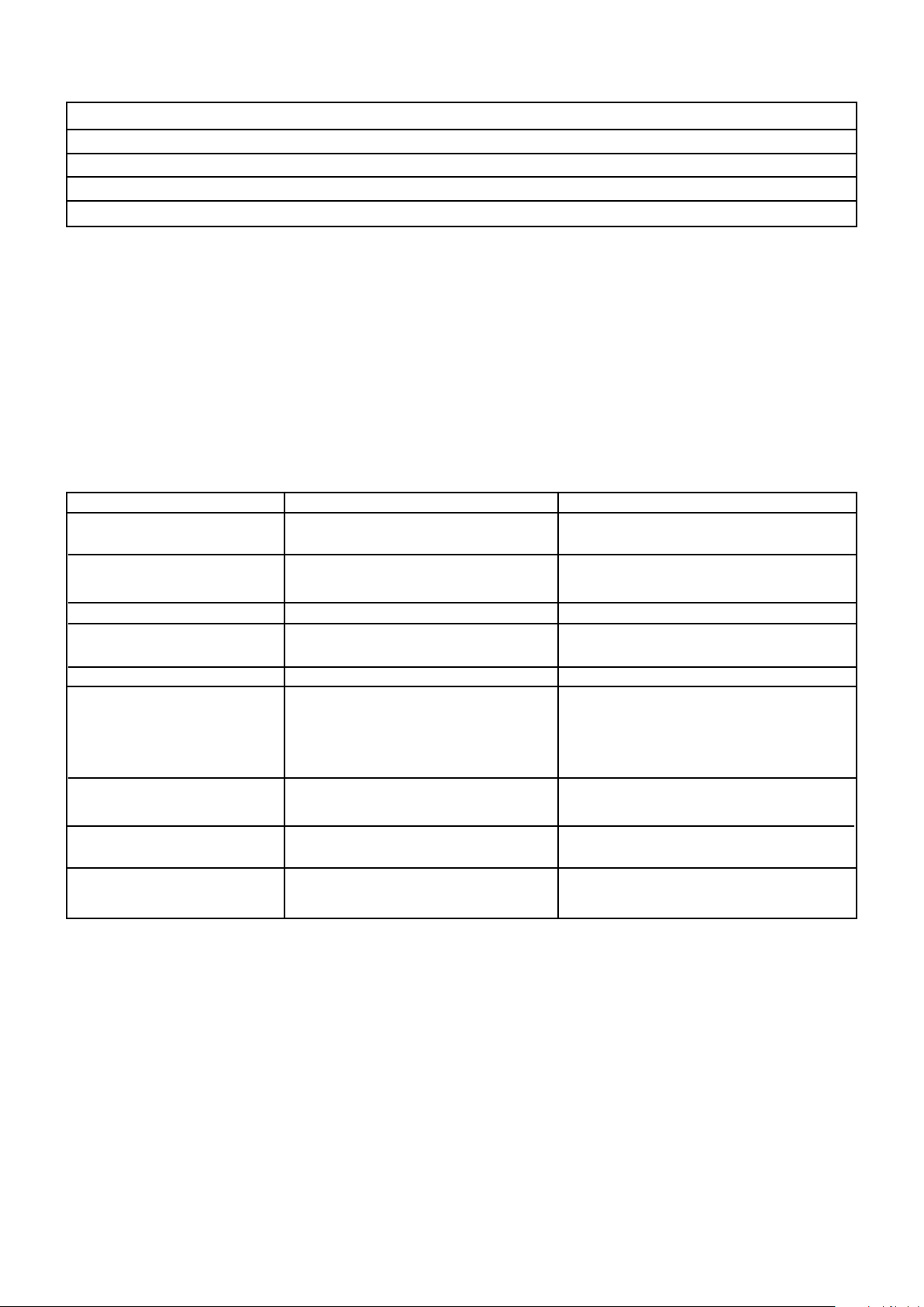
Especicaciones de la Parrilla
Quemador 4 quemadores
Tamaño del inyector 1,0 MM
Gas/Presión 11" por W.C
Potencia 11.700 BTU/H*3 (principal) 14.000 BTU/H*1 (brasas)
Estándar ANSI STD Z21.58-2018 Electrodomésticos a gas para cocinar al aire libre
INFORMACIÓN TÉCNICA Y DE SERVICIO
Este equipo está diseñado para ser utilizado en exteriores, únicamente con gas propano a una presión
de suministro de 11" por WC y debe ser reparado por una persona capacitada que siga las instrucciones
incluidas. Lea toda la documentación cuidadosamente.
SOLUCIÓN DE PROBLEMAS
Problema Causa posible Solución
El quemador no se enciende El cilindro de gas líquido propano Reemplazar con un cilindro lleno
con el sistema de encendido está vacío
Regulador defectuoso Haga revisar o reemplazar el
regulador
Obstrucciones en el quemador Limpie el quemador
Obstrucciones en la boquilla o en la Limpie la boquilla y la manguera de
manguera de gas gas
El alambre del electrodo esta suelto Reconecte el cable
Llama pequeña o retroceso Electrodo o cable dañado Cambe el electrodo y el cable
(fuego en el tubo del Obstrucciones en el quemador Limpie el quemador
quemador: se puede
escuchar un silbido o un
ruido de rugido)
Obstrucciones en la boquilla o en Limpie la boquilla y la manguera de
la manguera de gas gas
Condiciones de viento Utilice la parrilla en un lugar donde
esté más protegida contra el viento
Es difícil girar la perilla de La válvula de gas está atascada Reemplace la válvula de gas
la válvula de gas
57

KENMORE LIMITED WARRANTY
CON EL COMPROBANTE DE LA COMPRA, se aplica la siguiente garantía solo en el caso de que este equipo se instale, opere y
mantenga correctamente de acuerdo con todas las instrucciones suministradas.
POR UN AÑO a partir de la fecha de compra, este aparato está garantizado contra defectos en los materiales o mano de obra.
Todo aparato defectuoso recibirá reparación gratuita. Si el aparato no se puede reparar, se reemplazará de forma gratuita.
POR CINCO AÑOS a partir de la fecha de compra, cualquier quemador de acero inoxidable que se oxida o queme se
reemplazará sin cargo. * Si el óxido o el quemado tiene lugar durante el primer año, se instalará un nuevo quemador sin cargo.
Si el óxido o el quemado tiene lugar después del primer año, se suministrará un nuevo quemador pero no se instalará sin cargo.
Usted será responsable del costo de mano de obra de la instalación del quemador después del primer año a partir de la fecha
de compra. * Un representante autorizado de Sears debe vericar la oxidación o el quemado.
Para obtener detalles de la cobertura de la garantía para obtener reparaciones o repuestos gratuitos, visite la página web:
www.kenmore.com/warranty
La cobertura de la garantía excluye las baterías de ignición y la pérdida de pintura, decoloración o corrosión de partes de
la parrilla, las cuales constituyen piezas prescindibles que pueden desgastarse debido al uso normal dentro del período de
garantía, o son condiciones que pueden ser el resultado de un uso normal, un accidente o un mantenimiento inadecuado.
La cobertura de la garantía se anulará si este aparato se utiliza para otros nes que no sean domésticos.
Esta garantía cubre SOLO defectos en los materiales y en la mano de obra, y NO cubrirá lo siguiente:
1. Artículos prescindibles que pueden desgastarse debido al uso normal dentro del período de garantía, incluyendo, entre otros, las baterías,
bombillas de luz de base roscada y recubrimientos o acabados de supercie.
2. Un técnico de servicio para limpiar o mantener este aparato, o para instruir al usuario sobre la correcta instalación, operación y
mantenimiento de este.
3. Llamadas para recibir servicio técnico para corregir la instalación del aparato no realizada por agentes de servicio autorizados de Sears,
o para reparar problemas con los fusibles, los disyuntores y el cableado de la casa y los sistemas de plomería o suministro de gas que
resulten de dicha instalación.
4. El daño o la falla de este aparato como resultado de la instalación no realizada por agentes de servicio autorizados de Sears, incluyendo
toda instalación que incumpla con los códigos eléctricos, de gas o de plomería.
5. Daños o fallas de este aparato, incluyendo la decoloración u oxidación de la supercie, si no se opera y mantiene correctamente de
acuerdo con todas las instrucciones suministradas.
6. Daños o fallas de este aparato, incluyendo la decoloración u oxidación de la supercie, como resultado de un accidente, alteración, abuso,
mal uso o uso para otro propósito que no sea el previsto.
7. Daños o fallas de este aparato, incluyendo la decoloración u oxidación de la supercie, causado por el uso de detergentes, limpiadores,
productos químicos o utensilios que no sean los recomendados en las instrucciones suministradas con el producto.
8. Daños o fallas de este aparato causados por catástrofes naturales o de otro tipo, como inundaciones, incendios o tormentas.
9. Daños o fallas de partes o sistemas causados por modicaciones no autorizadas hechas a este aparato.
10. Haga revisar el equipo si la placa de modelo y serie está ausente o está alterada, o no se puede determinar fácilmente que contenga el
logotipo de certicación adecuado.
Exención de responsabilidad sobre las garantías implícitas; límites de resarcimiento
El único y exclusivo resarcimiento del Cliente bajo esta garantía limitada será la reparación o el reemplazo del producto según
lo dispuesto en este documento. Las garantías implícitas, incluyendo las garantías de comercialización o la adecuación para
un propósito en particular, están limitadas a un año para el aparato y cinco años para los quemadores, o el período más corto
permitido por la ley. El vendedor no será responsable por daños incidentales o consecuentes. Algunos estados y provincias no
permiten la exclusión o limitación de daños incidentales o consecuentes, o la limitación en la duración de las garantías implícitas
de comercialización o adecuación, por lo que estas exclusiones o limitaciones pueden no ser aplicables en su caso.
Esta garantía solo es válida solo para el uso del aparato en Estados Unidos.
Esta garantía le otorga derechos legales especícos, y también puede tener otros derechos que varían de un estado a otro.
Sears Brands Management Corporation, Homan Estates, IL 60179
58


Kenmore ®
Customer Care Hotline
To schedule in-home repair service
or order replacement parts
Para pedir servicio de reparación
a domicilio, y ordenar piezas
1-844-553-6667
www. kenmore. com
®