
MODEL NUMBER 917.256563
OWNER'S MANUAL
®
• Assembly
• Operation
• Customer Responsibilities
° Service and Adjustments
° Repair Parts
CAUTION: Read and follow all safety rules and instructions before operating this equipment,
FOR CONSUMER ASSISTANCE HOT LINE, CALL THiS TOLL FREE NUMBER: 1-B00-659-5917
SAFETY RULES
A
Safe Operation Practices for Ride-On Mowers
IMPORTANT: THIS CUTTING MACHINE IS CAPABLE OF AMPUTATING HANDS AND FEET AND THROWING OBJECTS.
FAILURE TO OBSERVE THE FOLLOWING SAFETY INSTRUCTIONS COULD RESULT IN SERIOUS INJURY OR DEATH.
I. GENERAL OPERATION
• Read, understand, and follow al! instructions in the manual
and on the machine before starting,
Only allow responsible adults, who are familiar with the
instructions,to operate the machine,
• Clear the area of objects such as rocks, toys, wire, etc,,
which could be picked up and thrown by the blade,
• Besuretheareaisclearofotherpeoplebeforemowing. Stop
machine ifanyone enters the area,
• Never carry passengers.
. Do not mow in reverse unless absolutely necessary. Always
look down and behind before and while backing.
. Be aware 0f the mower discharge direction and do not point
it at anyone. Do not operate the mower without either the
entire grass catcher or the guard in place.
• Slow down before turning.
• Never leave a running machine unattended. Always turn off
blades, set parking brake, stop engine, and remove keys
before dismounting.
• Turn off blades when not mowing.
• Stop engine before removing grass catcher or unclogging
chute.
• Mow only in daylight or good artificial light.
• Do not operate the machine while under the influence of
alcohol or drugs.
• Watch for traffic when operating near or crossing roadways.
, Use extra care when loading or unloading the machine into
a trailer or truck.
I|. SLOPE OPERATION
Slopes are a major factor related to loss-of-control and
tipover accidents, which can resul t in severe injury or death.
All slopes require extra caution. If you cannot back up the
slope or if you feel uneasy on it, do not mow it.
DO:
• Mow up and down slopes, not across.
• Remove obstacles such as rocks, tree limbs, etc.
• Watch for holes, ruts, or bumps. Uneven terrain could
overturn the machine. Tall grass can hide obstacles.
• Use slow speed. Choose a low gear so that you will not have
to stop or shift while on the slope.
• Follow the manufacturer's recommendations for wheel
weights or counterweights to improve stability.
. Use extra care with grass catchers or other attachments.
These can change the stability of the machine.
• Keep all movement on the slopes stow and gradual Do not
make sudden changes in speed or direction.
,, Avoid starting or stopping on a slope. If tires lose traction,
disengage the blades and proceed slowly straight down the
slope.
DO NOT:
• Donot tum on slopes unless necessary, andthen, turn slowly
and gradually downhill, if possible.
• Do not mow near drop-offs, ditches, or embankments. The
mower could suddenly tum over ifa wheel is over the edge
of a cliff or ditch, or if an edge caves in.
• Do not mow on wet grass. Reduced traction could cause
sliding.
• Do not try to stabilize the machine by putting your foot on the
ground.
= Do not use grass catcher on steep slopes.
Ill. CHILDREN
Tragic accidents can occur if the operator is not alert to the
presence of children. Children are often attracted to the
machine and the mowing activity. Never assume that
children will remain where you last saw them.
• Keep childrenout of the mowing area and under the watchful
care of another responsible adult.
, Be alert and turn machine off if children enter the area.
• Before and when backing, look behind and downfor small
children.
• Never carry children. They may fall off and be seriously
injured or interfere with safe machine operation.
• Never al ow children to operate the machine.
• Use extra care when approaching blind comers, shrubs,
trees, or other objects that may obscure vision.
IV.
o
o
SERVICE
Use extra care in handling gasoline and other fuels. They are
flammable and vapors are explosive.
Use only an approved container.
Never remove gas cap or add fuel with the engine
running. Allow engine to cool before refueling. Do not
smoke.
Never refuel the machine indoors.
Never store the machine or fuel container inside where
there is an open flame, such as a water heater.
Never run a machine inside a closed area.
Keep nuts and botts, especially blade attachment bolts, tight
and keep equipment in good condition.
Never tamper with safety devices. Check their proper
operation regularly.
Keep machine free of grass, leaves, or other debris build-up.
Clean oil or fue! spillage. Allow machine to cool before
storing.
Stop and inspect the equipment if you strike an object.
Repair, if necessary, before restarting.
Never make adjustments or repairs with the engine running.
Grasscatcher components are subject to wear, damage, and
deterioration, which could expose moving parts or allow
objects to be thrown. Frequently check components and
replace with manufacturer's recommended parts, when nec-
essary.
Mower blades are sharp and can cut. Wrap the blade(s) or
wear gloves, and use extra caution when servicing them.
Check brake operation frequently. Adjust and service as
required.
A
Look for this symbol to point out im-
portant safety precautions, It means
CAUTION!!! BECOMEALERT!!! YOUR
SAFETY IS INVOLVED.
A
CAUTION: Always disconnect spark plug
wire and place wire where it can not contact
spark plug in order to prevent accidental
starting when setting up, transporting,
adjusting or making repairs.
WARNING A
The engine exhaust from this product con-
tains chemicals known to the State of Califor-
nia to cause cancer, birth defects, or other
reproductive harm.

CONGRATULATIONS on your purchase of a Sears
Tractor. It nas been designed, engineered and manufac-
tured to gwe you the best possible deoendability and
performance.
Should you experience any problem you cannot easily
remedy, please contact your nearest Sears Authorized
Service Center/Department. We have competent, well-
trained technicians and the prooer tools to service or repair
this tractor.
Please read and retain this manual. The instructions will
enable you to assemble and maintain your tractor properly.
Always observe the "SAFETY RULES".
MODEL
NU MBER 917.256563
SERIAL
NUMBER
DATEOFPURCHASE
THE MODELAN D SERIAL NUMBERS WILL BE FOUND
ON A PLATE UNDER THE SEAT.
YOU SHOULD RECORD BOTH SERIAL NUMBER AND
DATE OF PURCHASE AND KEEP IN A SAFE PLACE
FOR FUTURE REFERENCE.
MAINTENANCE AGREEMENT
A Sears Maintenance Agreement is available on this prod-
uct. Contact your nearest Sears store for details.
CUSTOMER RESPONSIBILITIES
• Read and observe the safety rules.
o Follow a regular schedule in maintaining, caring for and using
your tractor.
• Follow the instructions under "Customer Resoonsibilities"
and "Storage" sections of this owner's manual.
WARNING: This tractor is equipped with an internal
combustion eng_ne ana should not be used on or near any
un_mprovea forest-covered brush-covered or grass-cov-
ere(] land unless the engine's exhaust system is equipped
with a spark arrester meehng applicable local or state laws
(if any). If a spark arrester is used, it should be maintained
in effective working oreer by tt_e operator.
PRODUCT SPECIFICATIONS
HORSEPOWER: 19.0
GASOLINE CAPACITY 3.5 GALLONS
AND TYPE: UNLEADED REGULAR
OIL TYPE (API-SFiSG): SAE 30 (above 32°F)
SAE 5W-30 (below 32°F)
OIL CAPACITY: 3.0 PINTS
SPARK PLUG: CHAMPION RJlg_M
(GAP: .030' ) STD361458
VALVE CLEARANCE: INTAKE: .004" - .006"
EXHAUST: .007" - .009"
GROUND SPEED (MPH): FORWARD:
1st 1.1
2nd 1.5
3rd 2.3
4th 3.5
5th 4.4
6th 5.7
REVERSE: 1.7
TIRE PRESSURE: FRONT: "4 PSI
REAR: 10 PSI
CHARGING SYSTEM: 3 AMPS BATTERY
5 AMPS HEADLIGHTS
ATTERY: AMP!HR: 30
MIN. CCA: 240
CASE SIZE: U1R
BLADE BOLT TORQUE: 30-35 FT LBS.
In the state of California the above is reauired by law
(Section 4442 of the California Public Resources Code).
Other states may have similar laws, Federal laws apply on
federa lands, A spark arrester for the muffler is available
through your nearest Sears Authorized Service Center/
De 3artment (See REPAI R PARTS section of this manual).
LIMITED TWO YEAR WARRANTY ON CRAFTSMAN RIDING EQUIPMENT
Foi two I2) years from the date of purchase, if this Craftsman eliding Equipment is maintained, lubricated and tuned up according
to the instructions in the owner's manual. Sears will repair or replace, free of charge, any parts fet]nd to be defective in material or
workmanship.
"l'his Warranty does not cover:
• Expendable items which become worn during normal use. such as blades, spark plugs, air cleaners, belts, etc.
• Tire replacement or repair caused by punctures from outside oblects, such as nails, thorns, stumps, or gJass.
• Repairs necessary because of oaerator abuse, negligence, improper storage or accident or the failure to maintain the
equipment according to the instructions contained in the owner's manual.
Riding equipment used for commercia or rental pumoses.
LIMITED 90 DAY WARRANTY ON BATTERY
For ninety (90) days from date of purcnase, if any battery included with this riding equipment proves defective q material or
workmanship and our testing determines the battery will not hold a charge, Sears will replace the battery at no charge,
N-HOME WARRANTY SERVICE ON YOUR CRAFTSMAN RIDING EQUIPMENT tS AVAILABLE AT NO-CHARGE FOR 30
DAYS FROM THE DATE OF PURCHASE. PLEASE CONTACT YOUR NEAREST SERVICE CENTER. AFTER 30 DAYS FROM
THE DATE OF PURCHASE. WARRANTY SERVICE iS AVAILABLE BY TAKING YOUR CRAFTSMAN RIDING EQUIPMENT TO
YOUR NEAREST SEARS SERVICE CENTER. (IN-HOME WARRANTY SERVICE WILL STILL BE AVAILABLE AFTER 30 DAYS
FROM THE DATE OF PURCHASE BUT A STANDARD TRIP CHARGE WILL APPLY.) THIS WARRANrY APPLIES ONLY
WHILE THIS PRODUCT IS iN THE UNITED STATES.
This Warranty gives you specific legal rights, and you may also have other rights which may vary from state to state.
SEARS, ROEBUCK AND CO., D/8!7 WA, HOFFMAN ESTATES, IL 60179
3
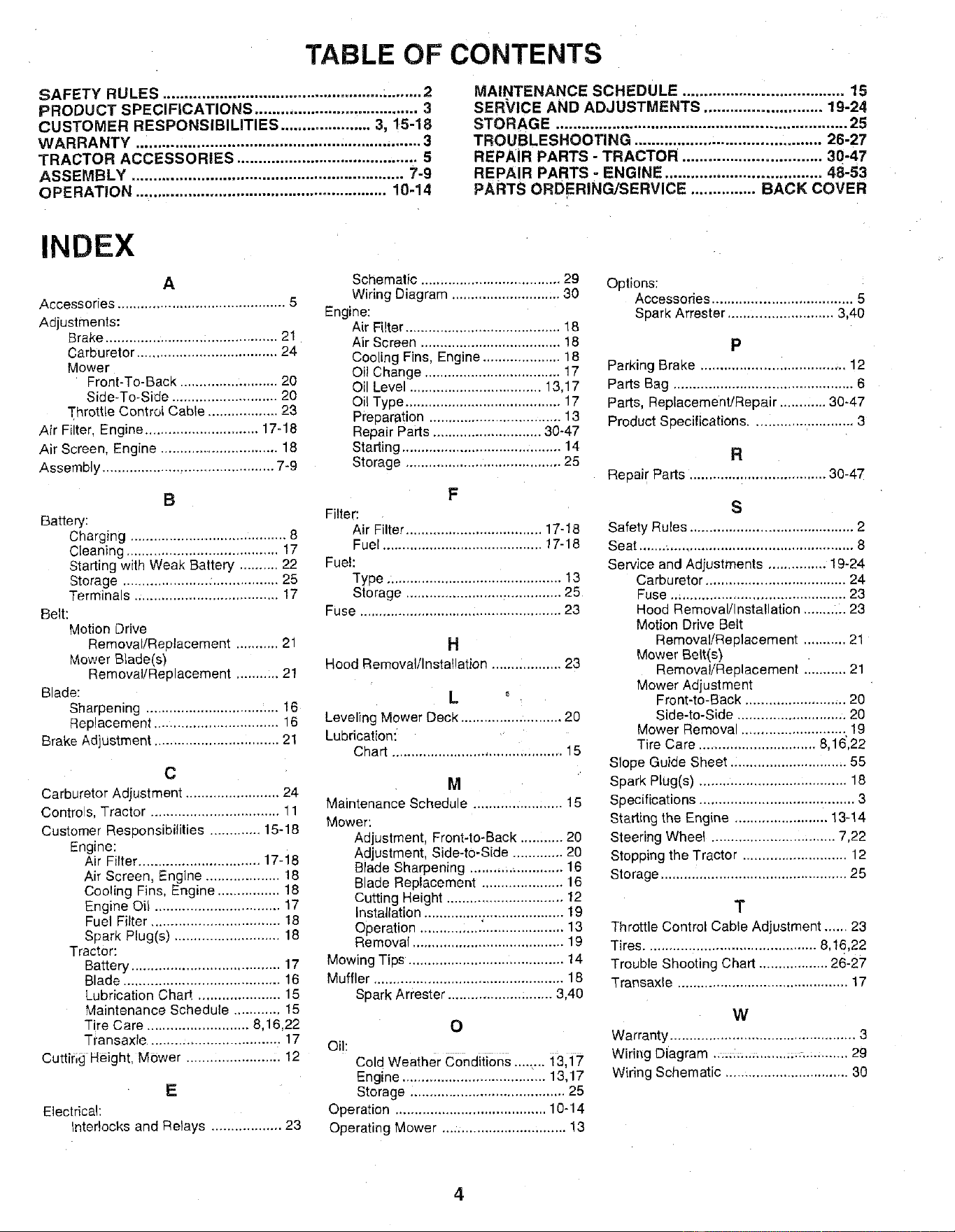
TABLE OF CONTENTS
SAFETY RULES ............................................................ 2
PRODUCT SPECIFICATIONS ...................................... 3
CUSTOMER RESPONSIBILITIES ..................... 3, 15-18
WARRANTY .................................................................. 3
I"RACTOR ACCESSORIES .......................................... 5
ASSEMBLY ............................................................... 7-9
OPERATION .......................................................... 10-14
MAINTENANCE SCHEDULE ..................................... 15
SERVICE AND ADJUSTMENTS ........................... 19-24
STORAG E ................................................................... 25
TROUBLESHOOTING ........................................... 26-27
REPAIR PARTS - TRACTOR ................................ 30-47
REPAIR PARTS - ENGINE .................................... 48-53
PARTS ORDERING/SERVICE ............... BACK COVER
INDEX
A
Accessories ........................................... 5
Adjustments:
Brake ......................... :.................. 21
Carburetor .................................... 24
Mower
Front-To-Back ......................... 20
Side-To-Side ........................... 20
Throttle Control Cable ................... 23
Air Filter, Engine ............................. 17-18
Air Screen, Engine ............................... 18
Assembly ............................................ 7-9
B
Battery:
Charging ......................................... 8
Cleaning ....................................... 17
Starting with Weak Battery .......... 22
Storage ...................... ;................. 25
Terminals ..................................... 17
Belt:
Motion Drive
Removal/Replacement ........... 21
Mower Blade(s)
Removal/Replacement ........ :.. 21
Blade:
Sharpening .............................. '.... 16
Replacement ................................ 16
Brake Adjustment ................................ 21
C
Carburetor Adjustment ........................ 24
Controls, Tractor ................................. 11
Customer Responsibilities ............. 15-18
Engine:
Air Filter ............................... 17-i8
Air Screen, Engine ................... 18
Cooling Fins, Engine ................ 18
Engine Oi! ................................ 17
Fuel Filter ................................. 18
Spark Plug(s) ........................... 18
Tractor:
Battery ...................................... 17
Blade ........................................ 16
Lubrication Chart ..................... 15
Maintenance Schedule ............ 15
Tire Care .......................... 8,16,22
Transaxle .................................. 17
Cuttirig Height, Mower ...................... :. 12
E
Electrical:
Inter!ocks and Relays .................. 23
Schematic .................................... 29
Wiring Diagram ............................ 30
Engine:
Air Fiter ....................................... 18
Air Screen .................................... 18
Cooling Fins. Engine ................... 18
Oil Change ................................... 17
Oil Level .................................. 13.17
Oil Type ....................................... 17
Preparation .................................. 13
Repair Parts ............................ 30-47
Starting ......................................... 14
Storage ........................................ 25
F
Filter:
Air Filter .................................. 17-18
Fuel ......................................... 17-18
Fuel:
Type ............................................. 13
Storage ....................................... 25
Fuse ................................................. 23
H
Hood Removal/Installation .................. 23
L
Leveling Mower Deck .......................... 20
Lubrication:
Chart .......................................... 15
M
Maintenance Schedule ....................... 15
Mower:
Adjustment, Front-to-Back ........... 20
Adjustment Side-to-Side ............. 20
Blade Sharpening ........................ 16
Blade Replacement ..................... 16
Cutting Height .............................. 12
Installation ............... . .................... 19
Operation ..................................... 13
Removal ....................................... 19
Mowing Tips ........................................ 14
Muffler ................................................. 18
Spark Arrester ........................... 3,40
0
Oil:
Cold Weather conditions........ 13,17
Engine ..................................... 13,17
Storage ........................................ 25
Operation ....................................... 10-14
Operating Mower ................................ 13
Options:
Accessories ................................... 5
SDar_ Arrester ........................... 3,40
P
Parking Brake ..................................... 12
Parts Bag .............................................. 6
Pads, Replacement/Repair ............ 30-47
Product Soecifications .......................... 3
R
Reoair Parts ................................... 30-47
S
Safety Rules .......................................... 2
Seat ....... ;............................................... 8
Service and Adjustments .............. 19-24
Carburetor .................................... 24
Fuse ............................................. 23
Hood Removal/I nstallation ........... 23
Motion Drive Belt
Removal/Reolacement ........... 21
Mower Belt(s)
Remova/Re 91acement ........... 21
Mower Adjustment
Front-to-Back .......................... 20
Side-to-Side ............................ 20
Mower Removal ........................... 19
Tire Care .............................. 8.16,22
Slope Guide Sheet .............................. 55
SoarK Plug(s) ...................................... 18
Soecifications ........................................ 3
Starling the Engine ........................ 13-14
Steering Wheel .............................. 7,22
Stopping the Tractor ........................... 12
Storage ................................................ 25
T
Throttle Control Cable Adjustment ...... 23
Tires ............................................ 8,16,22
Trouble Shooting Chart .................. 26-27
Transaxle ............................................ 17
W
Warranty ................................................ 3
Wiring Diagram .: ._:._:: ........;;::_........... 29
Wiring Schematic ................................ 30
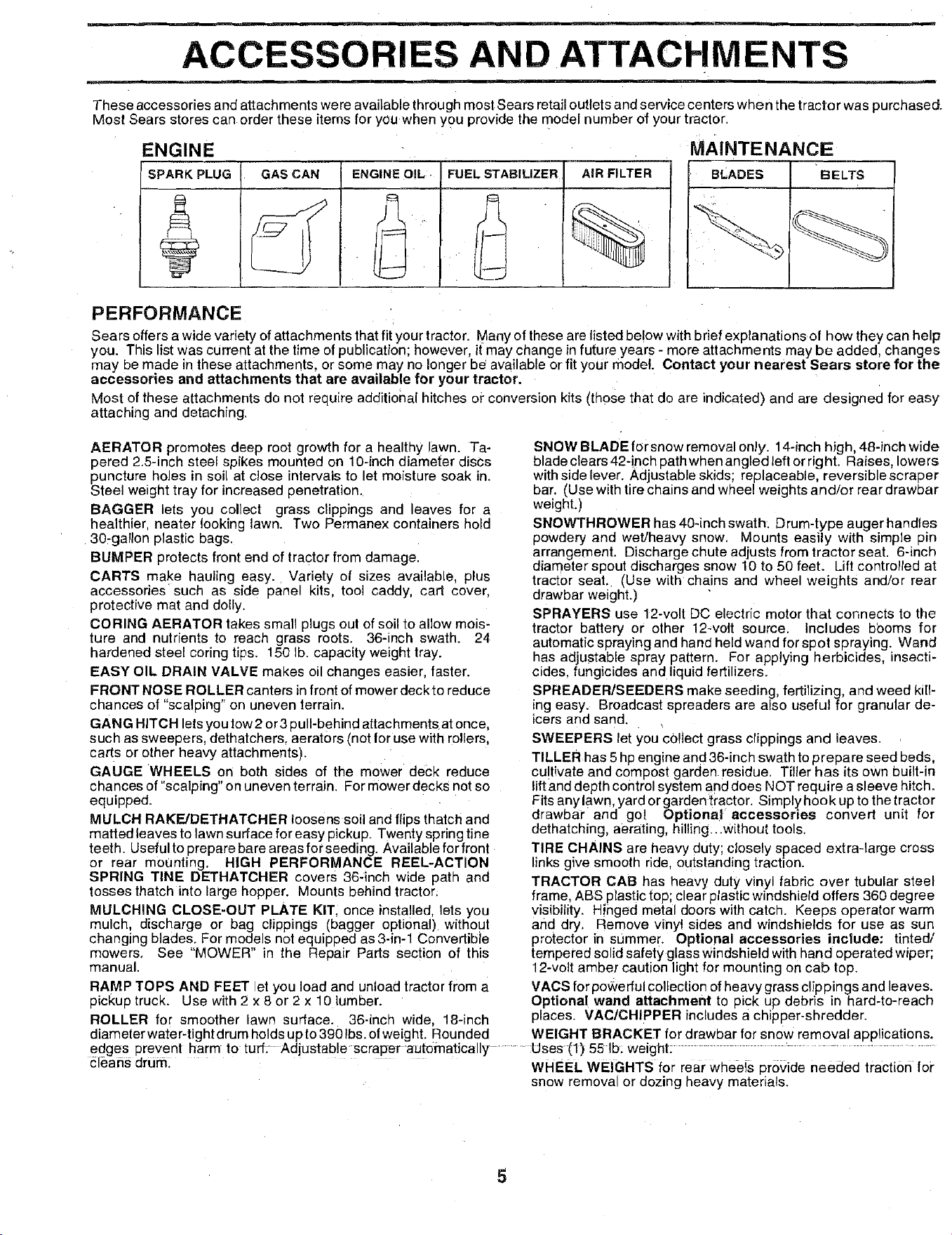
ACCESSORIES AND ATTACHMENTS
These accessories and attachments were aVailable through most Sears retail outlets and service centers when the tractor was purchased.
Most Sears stores can order these items for you when yo u provide the model number of your tractor.
MAINTENANCE
ENGINE
SPARK PLUG GAS CAN ENGINE OIL, FUEL STABILIZER
AIR FILTER
BLADES BELTS
PERFORMANCE
Sears offers a wide variety of attachments that fit your tractor. Many of these are listed below with brief explanations of how they can help
you. This list was current at the time of publication; however, it may change in future years - more attachments may be added, changes
may be made in these attachments, or some may no longer be available or fit your model. Contact your nearest Sears store for the
accessories and attachments that are available for your tractor.
Most of these attachments do not require additional hitches or conversion kits (those that do are indicated) and are designed for easy
attaching and detaching,
AERATOR promotes deep root growth for a healthy lawn. Ta-
pered 2.5-inch steel spikes mounted on 10-inch diameter discs
puncture holes in soil at close intervals to let moisture soak in.
Steel weight tray for increased penetration.
BAGGER lets you collect grass clippings and leaves for a
healthier, neater looking lawn. Two Permanex containers hold
30-ga!lon plastic bags.
BUMPER protects front end of tractor from damage•
CARTS make hauling easy. Variety of sizes available, plus
accessories' such as side panel kits, tool caddy, cart cover,
protective mat and dolly.
CORING AERATOR takes small plugs out of soil to allow mois-
ture and nutrients to reach grass roots• 36-inch swath. 24
hardened steel coring tips. 150 lb. capacity weight tray.
EASY OIL DRAIN VALVE makes oil changes easier, faster.
FRONT NOSE ROLLER canters in front of mower deck to reduce
chances of "scalping" on uneven terrain.
GANG HITCH lets you tow2 or3 pull-behind attachmentsat once,
such as sweepers, dethatchers, aerators (not for use with rollers,
carts or other heavy attachments).
GAUGE WHEELS on both sides of the mower deck reduce
chances of "scalping" on uneven terrain. For mower decks not so
equipped.
MULCH RAKFJDETHATGHER loosens soil and flips thatch and
matted leaves to lawn surface for easy pickup. Twenty spring tine
teeth. Useful to prepare bare areas for seeding. Available for front
or rear mounting. HIGH PERFORMANCE REEL-ACTION
SPRING TINE DETHATCHER covers 36-inch wide path and
tosses thatch into large hopper. Mounts behind tractor;
MULCHING CLOSE-OUT PLATE KIT, once insta!led, lets you
mulch, discharge or bag clippings (bagger optional) without
changing blades. For models not equipped as 3-in-1 Convertible
mowers, See "MOWER" in the Repair Parts section of this
manual•
RAMP TOPS AND FEET let you load and unload tractor from a
pickup truck. Use with 2 x 8 or 2 x 10 lumber.
ROLLER for smoother lawn surface. 36-inch wide, 18-inch
diameter water-tight drum holds up to 390 Ibs. of weight. Rounded
SNOW BLADE forsnow removal only. 14-inch high, 48-inch wide
bladeclears42-inch pathwhenangledleft orright. Raises, lowers
with side lever. Adjustable skids; replaceable, reversible scraper
bar. (Use with tire chains and wheel weights and/or rear drawbar
weight.)
SNOW'rHROWER has 40-inch swath• Drum-type auger handles
powdery and wet/heavy snow. Mounts easily with simple pin
arrangement. Discharge chute adjusts from tractor seat. 6-inch
diameter spout discharges snow 10 to 50 feet. Lift controlled at
tractor seat. (Use with chains and wheel weights and/or rear
drawbar weight.)
SPRAYERS use 12-volt DC electric motor that connects to the
tractor battery or other 12,volt source. Includes b0oms for
automatic spraying and hand held wand for spot spraying. Wand
has adjustable spray pattern. For applying herbicides, insecti-
cides, fungicides and liquid fertilizers.
SPREADER/SEEDERS make seeding, fertilizing, and weed kill-
ing easy. Broadcast spreaders are also useful for granular de-
icers and sand.
SWEEPERS let you cOllect grass clippings and leaves.
TILLER has 5 hp engine and 36-inch swath to prepare seed beds,
cultivate and compost garden residue• Tiller has its own built-in
lift and depth control system and does NOT require a sleeve hitch.
Fits any lawn, yard or garden tractor. Simplyhook up to the tractor
drawbar and go! Optional accessories convert unit for
dethatching, aerating, hilling:..without tools.
TIRE CHAINS are heavy duty; ctosely spaced extra-large cross
links give smooth ride, outstanding traction.
TRACTOR CAB has heavy duty vinyl fabric over tubular steel
frame, ABS plastic top; clear plastic windshield offers 360 degree
visibility. Hinged metal doors with catch. Keeps operator warm
and dry, Remove vinyl sides and windshields for use as sun
protector in summer. Optional accessories include: tinted/
tempered solid safety glass Windshield with hand operated wiper;
12-volt amber caution light for mounting on cab top.
VAGS for powerful collection ofheavy grass clip pin gs and leaves.
Optional wand attachment to pick up debris in hard-to-reach
places. VAC/CHIPPER includes a chipper-shredder.
WEIGHT BRACKET for drawbar for snow removal applications.
edges prevent harm to turf. Adjustablescraper automatically ..... Uses (1) 55 Ib: weight: .......
cleaffs drum_ WHEEL WEIGHTS for rear wheels provide needed traction for
snow removal or dozing heavy materials.
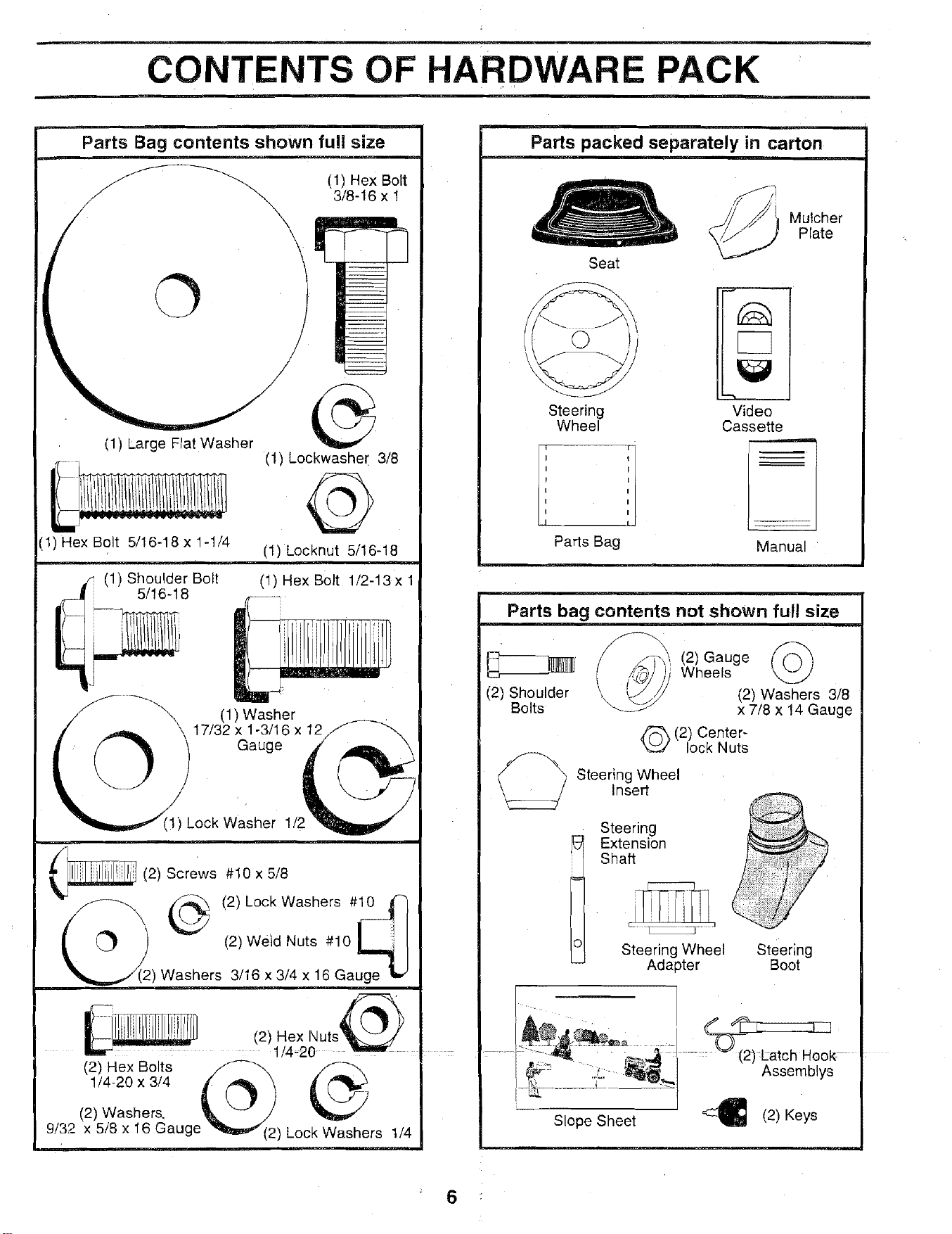
CONTENTS OF HARDWARE PACK
Parts Bag contents shown full size
©
(1) Hex Bolt
3/8-16 x 1
(1) Large Flat Washer
(1) Hex Bolt 5/16-18 x 1-1/4
(1) Lockwasher 3/8
(1) kocknut 5/16-18
i
(1) Hex Bolt 1/2-13x 1
(1) Washer
\ 17/32 x 1-3/16 x 12
Gauge
Lock Washer 1/2
(2) Screws #10 x 5/8
(2) Lock Washers #_
(2) we'td Nuts #10 _'_1
,Washers 3/16 x 3/4 x 16 Gauge _'
1/4-20X3/4 _: _ t
(2) Washer& _ _ /
9/32 x 5/8 x 16 Gauge "_m_1(2 ) Lo 1/4
Parts packed separately in carton
Seat
Mulcher
Plate
Steering Video
Wheel Cassette
Parts Bag Manual
Parts bag contents not shown full size
(2) Shoulder
Bolts
f-q-_,.>,,_(2) Gauge/
i /tL_'/) Wheels
" /// (2) Washers 3/8
'_/ x 7/8 x 14 Gauge
Q(2) Center-
lock Nuts
Steering Wheel
Insert
Steering
i extensi°_Shaft
L ...... J
Steering Wheel
Adapter
steering
Boot
Assemblys
Slope Sheet
(2) Keys
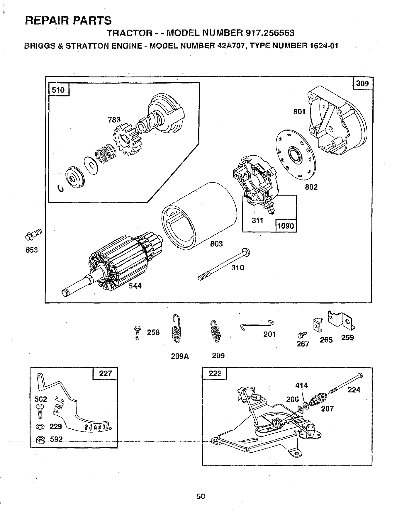
REPAIR PARTS
TRACTOR-- MODEL NUMBER 917.256563
BRIGGS & STRATTON ENGINE - MODEL NUMBER 42A707, TYPE NUMBER 1624-01
653
783
803
311
801
802
209A 209
201
267
265 259
414
206
5O
ASSEMBLY
Use
o
®
o
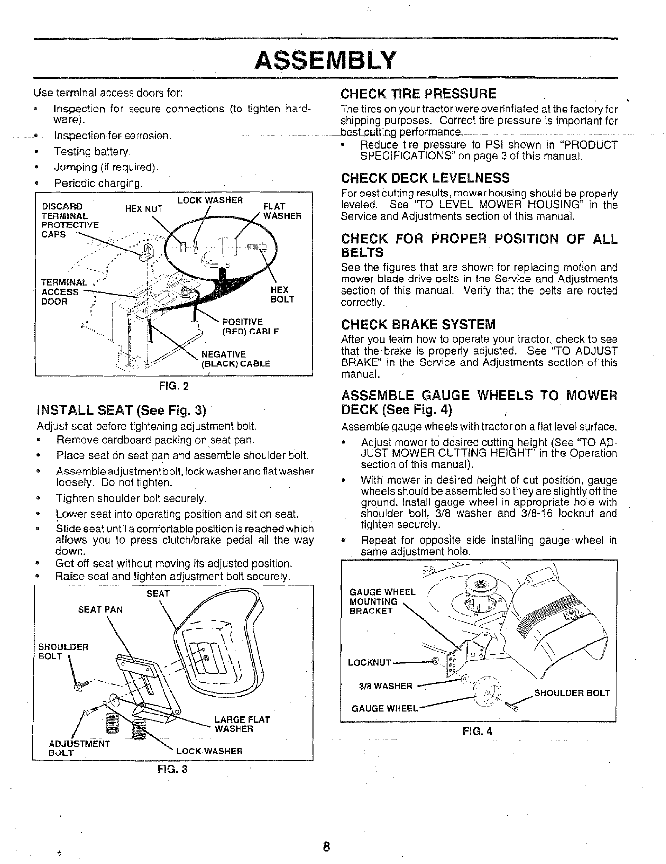
terminal access doors for: CHECK TIRE PRESSURE
Inspection for secure connections (to tighten hard- The tires on yourtractorwere overinfiated atthe factoryfor
ware), shipping purposes. Correct tire pressure is important for
Inspectien for eorrosien_ ............. _Joest.cutting performance- ..............
• Reduce tire pressure to PSi shown in "PRODUCT
Testing battery.
Jumping (if required).
Periodic charging.
DISCARD HEX NUT
TERMINAL
PR OTIECT|VE
CAPS
TERMINAL ,,'°_
ACCESS
DOOR ,/'
,; [
LOCK WASHER
FLAT
HEX
BOLT
(RED) CABLE
NEGATIVE
(BLACK} CABLE
FIG. 2
INSTALL SEAT (See Fig. 3)
Adjust seat before tightening adjustment bolt.
• RemoVe cardboard packing on seat pan.
• Place seat On seat pan and assemble shoulder bolt.
• Assemble adjustment bolt, lock washer and flat washer
loosely. Do not tighten.
• Tighten shoulder bolt securely.
= Lower seat into operating position and sit on seat.
, Slide seat until a comfortable position is reached which
allows you to press clutch/brake pedal all the way
down.
• Get off seat without moving its adjusted position.
Raise seat and tighten adjustment bolt securely.
SEAT
SEAT PAN
SHOULDER
BOLT
ADJUSTMENT
BOLT
LARGE FLAT
WASHER
LOCKWASHER
FiG. 3
SPECIFICATIONS" on page 3 of this manual.
CHECK DECK LEVELNESS
For best cutting results, mower housing should be properly
leveled. See "TO LEVEL MOWER HOUSING" in the
Service and Adjustments section of this manual.
CHECK FOR PROPER POSITION OF ALL
BELTS
See the figures that are shown for replacing motion and
mower blade drive belts in the Service and Adjustments
section of this manual. Verify that the belts are routed
correctly.
CHECK BRAKE SYSTEM
After you learn how to operate your tractor, check to see
that the brake is properly adjusted. See "TO ADJUST
BRAKE" in the Service and Adjustments section of this
manual.
ASSEMBLE GAUGE WHEELS TO MOWER
DECK (See Fig. 4)
Assemble gauge wheels with tractor on a flat level surface.
Adjust mower to desired cutting height (See "TO AD-
JUST MOWER CUTTING HEIGHT" in the Operation
section of this manual).
• With mower in desired height of cut position, gauge
wheels should be assembled so they are slightly off the
ground. Install gauge wheel in appropriate hole with
houlder bolt, 3/8 washer and 3/8-16 Iocknut and
tighten securely.
• Repeat for opposite side installing gauge wheel in
same adjustment hole.
GAUGE WHEEL /
MOUNTING _.
BRACKET
LOCKNUT_
3/8 WASHER
u
GAUGE WHEEL __
FIG. 4
SHOULDER BOLT
8
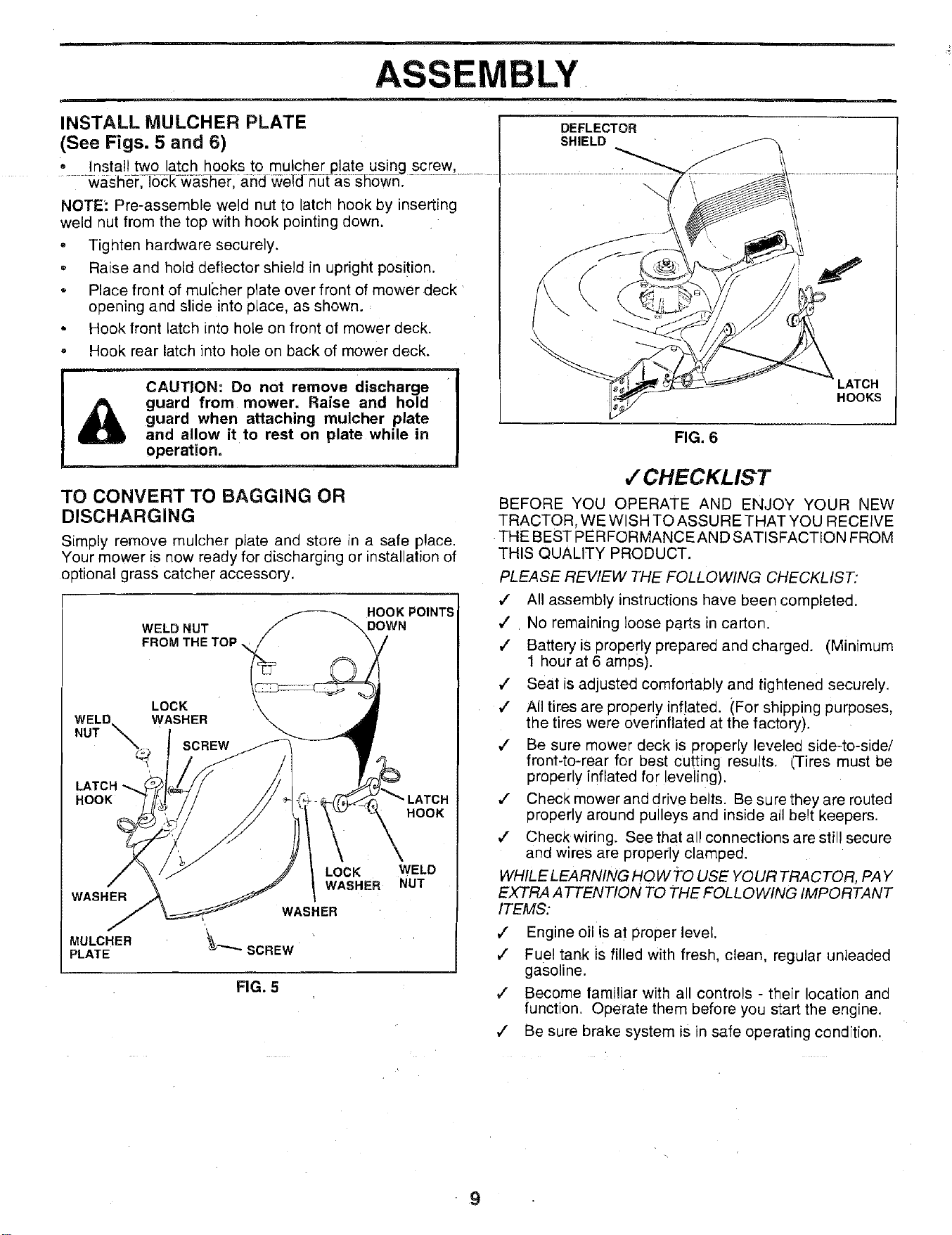
ASSEMBLY
INSTALL MULCHER PLATE
(See Figs. 5 and 6)
• Install two latch hooks to mulcher plate using screw,
washe=r,TocEw-a-s_erl ahd _efd nut _._ _h_wn.
NOTE _.Pre-assemble weld nut to latch hook by inserting
weld nut from the top with hook pointing down.
• Tighten hardware securely.
• Raise and hold deflector shield in upright position.
• Place front of mul_:her plate over front of mower deck
opening and slide into place, as shown.
• Hook front latch into hole on front of mower deck.
. Hook rear latch into hole on back of mower deck.
CAUTION: Do not remove discharge
guard from mower. Raise and hold
guard when attaching mulcher plate
and allow it to rest on plato while in
operation.
&
TO CONVERT TO BAGGING OR
DISCHARGING
Simply remove mulcher plate and store n a safe place.
Your mower is now ready for discharging or installation of
optional grass catcher accessory.
HOOK POINTS
\\DOWN
WELD NUT
FROM THE TOP
"_ LATCH
HOOK
LOCK
WELD. WASHER
NUT _
N. SCREW
LATCH
HOOK
LOCK WELD
WASHER NUT
FIG. 5
WASHER
MULCHER
_LATE
DEFLECTOR
SHIELD
HOOKS
FIG. 6
•/ CHECKLIST
BEFORE YOU OPERATE AND ENJOY YOUR NEW
TRACTOR, WE WISH TO ASSU RE -I-HAT YOU RECEIVE
THE BEST PERFORMANCEAND SATISFACT!ON FROM
THIS QUALITY PRODUCT.
PLEASE REVIEW THE FOLLOWING CHECKLIST:
,/ All assembly instructions have been completed.
,/ No remaining loose parts in carton.
/ Battery is properly prepared and charged. (Minimum
1 hour at 6 amos).
,/ Seat is adjustea comfortably and tightened securely.
,/ All tires are properly inflated (For shipping purposes,
the tires were overintlated at the factory).
,/ Be sure mower deck is properly leveled side-to-side/
front-to-rear for aest cutting results. (Tires must be
properly inflated for leveling).
€" Check mower and drive belts. Be sure they are routed
properly around pulleys and inside all be!t keepers.
,/ Check wiring. See that all connections are still secure
and wires are propeny clamped.
WHILE LEARNING HOW TO USE YOUR TRACTOR, PAY
EXTRA ATTENTION TO THE FOLLOWING IMPORTANT
ITEMS:
€" Engine oil is at 3roper level.
,/ Fuel tank is filled with fresh, clean, regular unleaded
gasoline.
,/ Become familiar with all controls - their location ane
function. Ouerate them before you start the engne.
¢" Be sure brake system is in safe operating cond'tion.
9
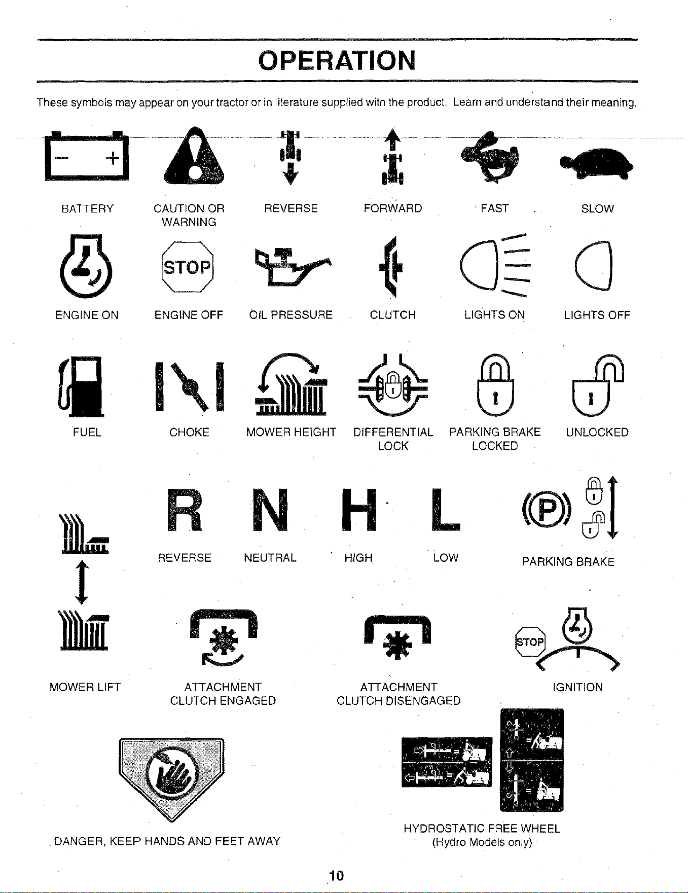
OPERATION
These symbols may appear on your tractor or in literature supplied with the product. Learn and understand their meaning.
& +
BATTERY CAUTION OR REVERSE FORWARD FAST SLOW
WARNING
ENGINE ON ENGINE OFF OIL PRESSURE CLUTCH LIGHTS ON LIGHTS OFF
FUEL CHOKE UNLOCKED
MOWER HEIGHT DIFFERENTIAL PARKING BRAKE
LOCK LOCKED
MOWER LIFT
REVERSE NEUTRAL
ATTACHMENT
CLUTCH ENGAGED
H L
HIGH Low
ATTACHMENT
CLUTCH DISENGAGED
PARKING BRAKE
IGNITION
.DANGER, KEEP HANDS AND FEET AWAY
HYDROSTATIC FREE WHEEL
(Hydro Models only)
10
m ....
OPERATION
KNOW YOUR TRACTOR
READ THIS OWNER'S MANUAL AND SAFETY RULES BEFORE OPERATING YOUR TRACTOR
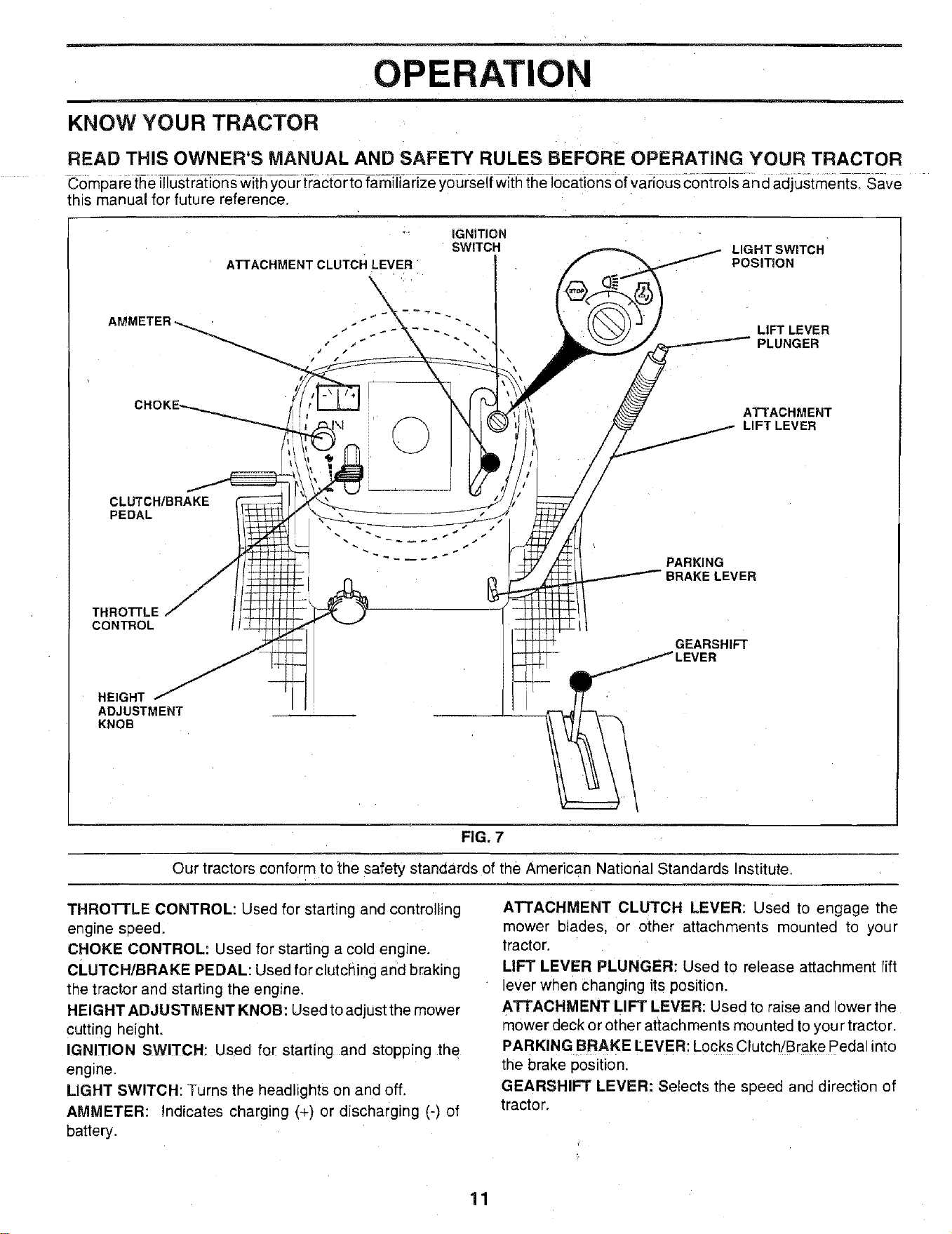
Compare t-hei[lustr_a_t]6r_s-w_{hyour tTactorto fa_n-iiiarizeyourseJf w_t_{he J66ati6ns of Various con_oJsan d adjustments.-_;ave
this manual for future reference.
ATTACHMENT CLUTCH LEVER
IGNITION
SWITCH
LIGHT SWITCH
POSITION
-"" "- LIFT LEVER
•" .,' PLUNGER
ATTACHMENT
LIFT LEVER
CLUTCH/BRAKE
PEDAL
THROTTLE
CONTROL
- :-:._::--
PARKING
BRAKE LEVER
GEARSHIFT
HEIGHT
ADJUSTMENT
KNOB
FIG. 7
Our tractors conform to the safety standards of the American National Standards Institute.
THROTTLE CONTROL: Used for starting and controlling
engine speed.
CHOKE CONTROL: Used for starting a cold engine.
CLUTCH/BRAKE PEDAL: Used for clutclling and braking
the tract.or and starting the engine.
HEIGHT ADJUSTMENT KNOB: Used to adjust the mower
cutting height.
IGNITION SWITCH: Used for starting and stopping the
engine.
LIGHT SWITCH: Turns the headlights on and off.
AMMETER: Indicates charging (+) or discharging (-) of
battery.
ATTACHMENT CLUTCH LEVER: Used to engage the
mower blades, or other attachments mounted to your
tractor.
LIFT LEVER PLUNGER: Used to release attachment lift
lever when Changing its position.
ATTACHMENT LIFT LEVER: Used to raise and lower the
mower deck or other attachments mounted to you r tractor.
PARKING BRAKE LEVER: Locks Clutch/Brake Pedal into
the brake position.
GEARSHIFT LEVER: Selects the speed and direction of
tractor.
OPERATION
m
m
I _ The operation of any tractor can result in foreign objects thrown into the eyes, which
I k _A_s Jl can result in severe eye damage. Always wear safety glasses or eye shields while
I ...... _ ............. operating you[ tractor o[ Rerform_p_ny_d_iustme_ts o.[repairs.__.W_J'ecommend a_ ......
| _ wide vision safety mask over the spectacles or standard safety glasses.
iL
HOW TO USE YOUR TRACTOR
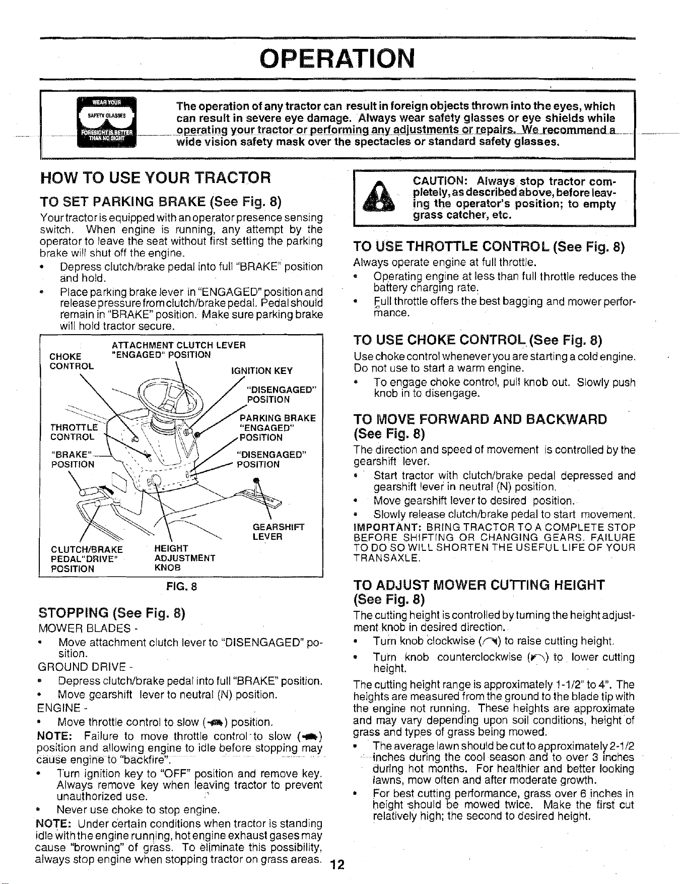
TO SET PARKING BRAKE (See Fig. 8)
Your tractoris equipped with an operator presence sensing
switch. When engine is running, any attempt by the
operator to leave the seat without first setting the parking
brake will shut off the engine.
° Depress clutch/brake pedal into full "BRAKE" position
and hold.
• Place parking brake lever in "ENGAGED" position and
releasepressurefromclutch/brake pedal. Pedal should
remain in "BRAKE" position. Make sure parking brake
will hold tractor secure.
ATTACHMENT CLUTCH LEVER
CHOKE "ENGAGED" POSITION
CONTROL IGNITION KEY
"DISENGAGED"
POSITION
THROTTLE
CONTROL
PARKING BRAKE
"ENGAGED"
"DISENGAGED"
POSITION POSITION
CLUTCH/BRAKE HEIGHT
PEDAL"DRIVE" ADJUSTMENT
POSITION KNOB
FIG. 8
GEARSHIFT
LEVER
STOPPING (See Fig. 8)
MOWER BLADES -
• Move attachment clutch lever to "DISENGAGED" po-
sition.
GROUND DRIVE -
• Depress clutch/brake pedal into full "BRAKE" position.
• Move gearshift lever to neutral (N) position.
ENGINE -
• Move throttle control to slow (,_) position.
NOTE: Failure to move throttle controlto slow (._b)
position and allowing engine to idle before stopping may
cause engine to "backfire".
• "[urn ignition key to "OFF" position and remove key.
Always remove key when leaving tractor to prevent
unauthorized use.
- Never use choke to stop engine.
NOTE: Under certain conditions when tractor is standing
idle Withthe engine running, hot engine exhaust gases may
cause "browning" of grass. To eliminate this possibility,
always stop engine when stopping tractor on grass areas. 12
CAUTION: Always stop tractor com-
pletely, as described above, before leav-
ing the operator's position; to empty
grass catcher, etc.
TO USE THROTTLE CONTROL (See Fig. 8)
Always operate engine at full throttle.
• Operating engine at less than full throttle reduces the
bal_terycharging rate:
• Full throttle offers the best bagging and mower perfor-
mance.
TO USE CHOKE CON'rROL(See Fig. 8)
Use choke control whenever you are starting a cold engine.
Do not use to start a warm engine.
• To engage choke control, pull knob out. Slowly push
knob in to disengage.
TO MOVE FORWARD AND BACKWARD
(See Fig. 8)
The direction and speed of movement is controlled by the
gearshift lever.
• Start tractor with clutch/brake pedal depressed and
gearshift lever in neutral (N) position.
. Move gearshift lever to desired position.
• Slowly release clutch/brake pedal to start movement.
IMPORTANT: BRING TRACTOR TO A COMPLETE STOP
BEFORE SHIFTING OR CHANGING GEARS. FAILURE
TO DO SO WILL SHORTEN THE USEFUL LIFE OF YOUR
TRANSAXLE.
TO ADJUST MOWER CU'I-FING HEIGHT
(See Fig. 8)
The cutting height iscontrolled by turning the height adjust-
ment knob in desired direction.
• Turn knob Clockwise (F_) te raise cutting height.
* Turn knob counterclockwise (lf'_)to lower cutting
height.
The cutting height range is approximately 1-1/2" to 4". The
heights are measured from the ground to the blade tip with
the engine not running. These heights are approximate
and may vary depending upon soil conditions, height of
grass and types of grass being mowed.
• The average lawn should be cut to approximately 2-1/2
: inches during the cool season and to over 3 inches
during hot months. For healthier and better looking
lawns, mow often and after moderate growth.
• For best cutting performance, grass over 6 inches in
height "should be mowed twice. Make the first cut
relatively high; the second to desired height.
OPERATION
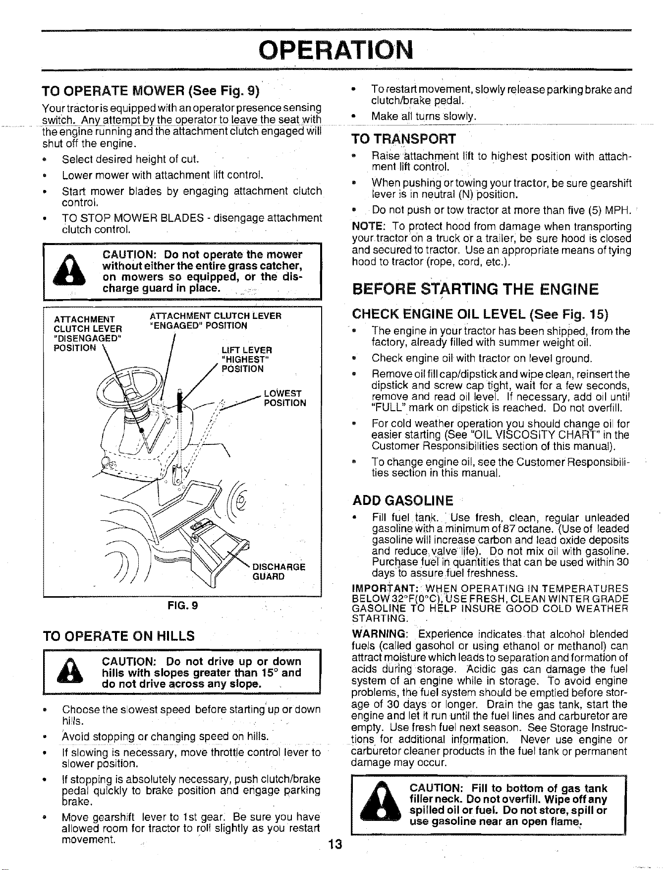
TO OPERATE MOWER (See Fig. 9) • To restart movement, slowly release parking brake and
clutch/brake pedal.
Your tractor is equipped with an operator presence sensing
switch. An_ attemj3t by the operator to leave the seat with • Make all turns slowly.
t h-een-g]ne running an-elt_heattachment €lutch engaged will
shut off the engine. TO TRANSPORT
• Select desired qeight of cut.
• Lower mower with attachment ift control.
• Start mower blades by engaging attachment clutch
control,
TO STOP MOWER BLADES - disengage attachment
Clutch control.
i
CAUTION: Do not operate the mower
without either the entire grass catcher,
on mowers so equipped, or the dis-
charge guard in place ....
- Raise attachment lift to highest position with attach-
ment lift control.
- When pushing or towing your tractor, be sure gearshift
ever is n neutral (N) position.
• Do not oush or tow tractor at more than five (5) MPH.
NOTE: To orotect hood from damage when transporting
your tractor on a truck or a trailer, be sure hood _sclosed
and securedto tractor. Use an appropriate means of tying
hood to tractor (rope, cord, etc.).
BEFORE STARTING THE ENGINE
FIG. 9
TO OPERATE ON HILLS
L
!
CAUTION: Do not drive up or down I
hills with slopes greater than 15° and
I
do not drive across any elope.
, Choose the s owest speed before starting uo or down
hills.
• Avoid stopping or changing speed on hills.
• If slowing is necessary, move throttle control lever to
slower position,
• If stopping is absolutely necessary, push clutch/brake
pedal quickly to brake position and engage parking
brake.
• Move gearshift lever to 1st gear. Be sure you have
allowed room for tractor to roll slightly as you restart
movement.
CHECK ENGINE OIL LEVEL (See Fig. 15)
, The engine in your tractor has been shioued, from the
factory, already filled with summer weight oil.
• Check engine oil with tractor on level ground.
• Remove oil fill cap/dipstick and wipe clean, reinsert the
diostick and screw cap tight wait for a few seconds,
"emove an(] read oil level. If necessary, add od until
"FULL" mark on dipstick is reached. De not overfill.
= For cold weather operation you should change oi for
easier starting (See "OIL VISCOSITY CHART" in the
Customer Responsibilities section of this manual).
• To change engine oil, see the Customer Responsibili-
ties section in this manual.
ADD GASOLINE
• Fi]l fuel tank. Use fresh, clean, regular unleaded
gasoline With a minimum of 87 octane. (Use of leaded
gasoline will increase carbon and lead oxide deposits
an(] reduce_valve life). Do not mix oi with gasoline.
Purchase :fuel in quantities that can be usee within 30
daysto assure fuel freshness.
IMPORTANT: WHEN OPERATING IN TEMPERATURES
BELOW32°F(0°C), USE FRESH, CLEAN WINTER GRADE
GASOLINE TO HELP INSURE GOOD COLD WEATHER
STARTING.
WARNING: Experience indicates that alcohol blended
fuels (called gasohol or using ethano or methanol) can
attract moisture which leads to separation and formation of
acids during storage. Acidic gas can oamage the fuel
system of an engine while in storage. To avoid engine
problems, the fuel system should De emptied before stor-
age of 30 days or onger. Drain the gas tank, start the
engine and et it run until the fuel lines and carburetor are
empty. Use Iresh fue next season. See Storage Instruc-
tions for additional information. Never use engine or
carburetor cleaner products in the fuel tank or permanent
damage may occur.
CAUTION: Fill to bottom of gas tank
filler neck. Do not overfill. Wipe off any
spilled oil or fuel. Do not store, spill or
use gasoline near an open flame.
13
OPERATION
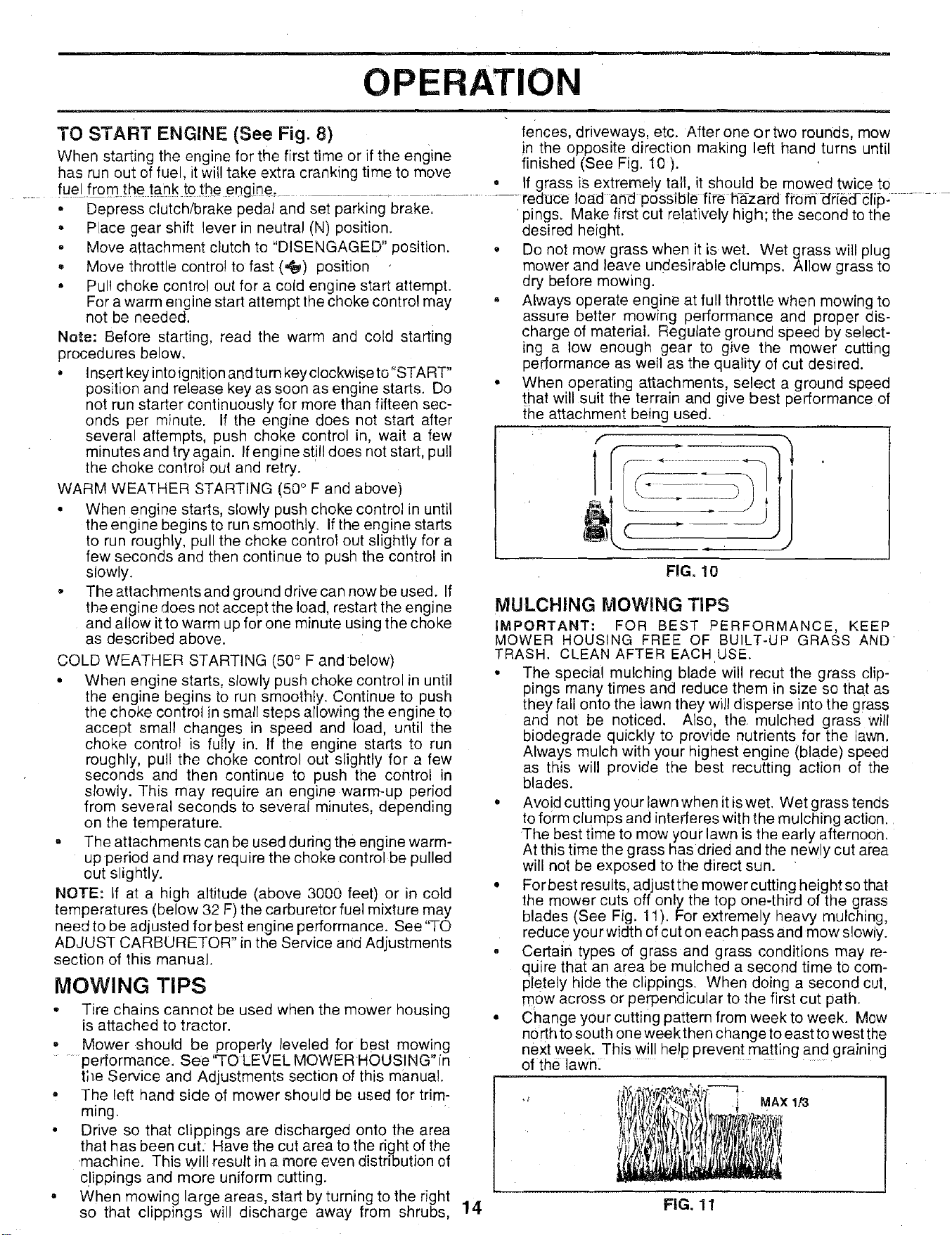
TO START ENGINE (See Fig. 8) fences, driveways, etc. After one or two rounds, mow
When starting the engine for the first time or if the engine in the opposite direction making left hand turns until
finished (See Fig. 10 ).
has run out of fuel, it will take extra cranking time to move
, , el
. _ fu#/from the tank to :[heerlg[ne............................. If grass is extremely tall, it should be mowed twice to
reduce load arid possible fire hazard fi'om-dfi6dclip: ....
, Depress clutch/brake pedal and set parking brake. 'pings. Make first cut relatively high the second to the
. Place gear shift lever in neutral (N) position, desired height.
- Move attachment clutch to "DISENGAGED" position.
, Move throttle control to fast (,_) position
• Pul! choke control out for a cold engine start attempt.
For a warm engine start attempt the choke control may
not be needed.
Note: Before starting, read the warm and cold starting
procedures below.
• Insertkeyintoignitionandturnkeyclockwiseto"START"
position and release key as soon as engine starts. Do
not run starter continuously for more than fifteen sec-
onds per minute. If the engine does not start after
several attempts, push choke control in, wait a few
minutes and try again. Ifengine still does not start, pull
the choke control out and retry.
WARM WEATHER STARTING (50° F and above)
• When engine starts, slowly push choke control in until
the engine begins to run smoothly. If the engine starts
to run roughly, pull the choke control out slightly for a
few seconds and then continue to push the control in
slowly.
• The attachments and ground drive can now be used. If
the engine does not accept the load, restart the engine
and allow itto warm up for one minute using the choke
as described above.
COLD WEATHER STARTING (50° F and below)
• When engine starts, slowly push choke control in until
the engine begins to run smoothly. Continue to push
the choke control in small steps allowing the engine to
accept small changes in speed and load, until the
choke control is fully in. If the engine starts to run
roughly, pull the choke control out slightly for a few
seconds and then continue to push the control in
slowly. This may require an engine warm-up period
from several seconds to several minutes, depending
on the temperature.
o The attachments can be used during the engine warm-
up period and may require the choke control be pulled
out slightly.
NOTE: if at a high altitude (above 3000 feet) or in cold
temperatures (below 32 F) the carburetor fuel mixture may
need to be adjusted for best engine performance. See "TO
ADJUST CARBURETOR" in the Service and Adjustments
section of this manual.
MOWING TIPS
= Tire chains cannot be used when the mower housing
is attached to tractor.
• Mower should be properly leveled for best mowing
performance. See 'q'O LEVEL MOWER HOUSING" in
the Service and Adjustments section of this manual.
• The [eft hand side of mower should be used for trim-
ming.
• Drive so that clippings are discharged onto the area
that has been cut. Have the cut area to the right of the
.machine. This will result in a more even distribution of
clippings and more uniform cutting.
• When mowing large areas, start by turning to the right
so that clippings will discharge away from shrubs,
Do not mow grass when it is wet. Wet grass will plug
mower and leave undesirable clumps, Allow grass to
dry before mowing.
Always operate engine at full throttle when mowing to
assure better mowing performance and proper dis-
charge of material, Regulate ground speed by select-
ing a low enough gear to give the mower cutting
performance as well as the quality of cut desired.
When operating attachments, select a ground speed
that will suit the terrain and give best performance of
the attachment being used.
f
i ,JJ
FIG. 10
MULCHING MOWING TIPS
IMPORTANT: FOR BEST PERFORMANCE, KEEP
MOWER HOUSING FREE OF BUILT-UP GRASS AND
TRASH. CLEAN AFTER EACH USE.
• The special mulching blade will recut the grass clip-
pings many times and reduce them in size so that as
they fall onto the tawn they will disperse into the grass
and not be noticed. Also, the mulched grass will
biodegrade quickly to provide nutrients for the lawn.
Always mulch with your highest engine (blade) speed
as this will provide the best recutting action of the
blades.
• Avoid cutting your lawn when it is wet. Wet grass tends
to form clumps and interferes with the mulching action.
The best time to mow your lawn is the early afternoon,
At this time the grass has dried and the newly cut area
will not be exposed to the direct sun.
• For best results, adjust the mower cutting height so that
the mower cuts off only the top one-third of the grass
blades (See Fig. 11). For extremely heavy mulching,
reduc e yourwidth of cut on each pass and mow slowly.
• Certain types of grass and grass conditions may re-
quire that an area be mulched a second time to com-
Pletely hide the clippings. When doing a second cut,
mow across or perpendicular to the first cut path.
• Change your cutting pattern from week to week. Mow
no rth to south one week then change to east to west the
next week. This will help prevent matting and graining
of the lawn:
MAX 1/3
14 FIG. 11
CUSTOMER RESP LITIES
s
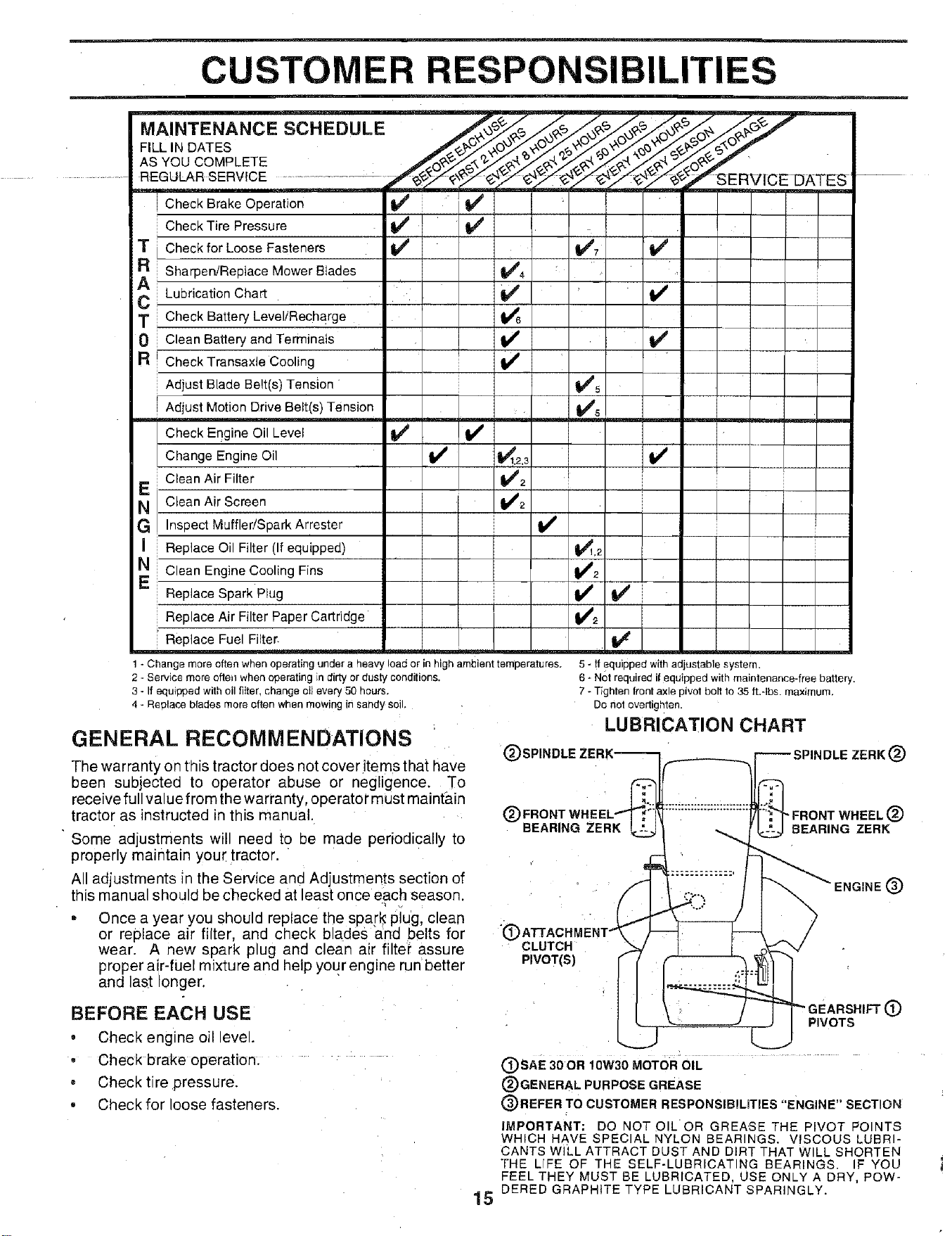
MAINTENANCE SCHEDULE
FILL IN DATES
AS YOU COMPLETE
REGULAR SERVICE
T
0
R
G
I
I Check Brake Operation
Check Tire Pressure
L Check for Loose Fasteners
Sharpen/Replace Mower Blades
Lubrication Chart
Check Battery Level/Recharge
Clean Battery and Terminals
I Check Transaxle Cooling
Adjust Blade Belt(s) Tension "
I Adjust Motion Drive Belt(s) Tension
Check Erlgine Oil Level
Change Engine Oil
Clean Air Filter
Clean Air Screen
Inspect Muffler!Spark Attester
Replace Oil Filter (If equipped)
Clean Engine Cooling Fins
Replace Spark Plug
Replace Air Filter Paper Cartridge
• Replace Fuel Filter-
v' v'
v'
_4
v'
v' i,,'
v'
V'2
V'
I
1 - Change more often when operating unaer a neavy load or in high aml31enttemperatures.
2 - Service more often when operating _ndirty or dusty conditions.
3 - If equipped with oil filter, change oiI every 50 hours.
4 - Replace blades more often when mowing in sandy soil.
GENERAL RECOMM ENDATIONS
The warranty on this tractor does not cover items that have
been subjected to operator abuse or negligence. To
receive full value from the warranty, operator must maintain
tractor as instructed in this manual.
Some adjustments will need to be made periodically to
properly maintain your tractor.
All adjustments in the Service and Adjustments section of
this manual should be checked at least once each season.
• Once a year you should replace the spark plug, clean
or replace air filter, and check blades and belts for
wear. A new spark plug and clean air filte_ assure
proper air-fuel mixture and help your engine run better
and ast longer.
BEFORE EACH USE
• Check engine oil level.
• Check brake operation:
• Check tire pressure.
• Check for loose fasteners.
v'7 v'
i/
v'
v%
i/'5
i/
t/
5 - Ifequippedwithadjustable system
6 - Netrequired ifequipped with maintenance-freebattery.
7 - Tighten front axle pivotboFtto 35 ft.-Ibs, maximum.
Do not overtighten.
LUBRICATION CHART
(_SPINDLE ZERK_ --SPINDLE ZERK (_)
(_) FRONT WHEEL_. ::::::::::::::::::::::::::
BEARING ZERK _
)ATI'ACHMENT_ r',.-,
(_sAE 30OR 10W30 MoTORolL
(_)GENERAL PURPOSE GREASE
(_)REFER TO CUSTOMER RESPONSIBILITIES "ENGINE" SECTION
iMPORTANT: DO NOTOIL OR GREASE THE PIVOT POINTS
WHICH HAVE SPECIAL NYLON BEARINGS. VISCOUS LUBRI-
CANTS WILL ATTRACT DUST AND DIRT THAT WILL SHORTEN
THE LIFE OF THE SELF-LUBRICATING BEARINGS. IF YOU
FEEL THEY MUST BE LUBRICATED, USE ONLY A DRY, POW-
DERED GRAPHITE TYPE LUBRICANT SPARINGLY.
15
FRONT WHEEL (_)
-_..>1-BEARING ZERK
CUSTOMER R SIBILITIES
TRACTOR TO SHARPEN BLADE (See Fig. 13)
Always observe safety rules when performing any mainte- Care should be taken to keep the blade balanced. An
nance, unbalanced blade will cause excessive vibration and even-
............................................... tua_damage t_: mower and erigine. ........................
BRAKE OPERATION
If tractor requires more than six (6) feet stopping distance
at high speed in highest gear, then brake must be adjusted.
(See "TO ADJUST BRAKE" in the Service and Adjust-
ments section of this manual).
TIRES
= Maintain proper air pressure in all tires (See "PROD-
UCT SPECIFICATIONS" on page 3 of this manual).
• Keep tires free of gasoline, oil, or insect control chemi-
cals which can harm rubber.
, Avoid stumps, stones, deep ruts, sharp objects and
other hazards that may cause tire damage.
BLADE CARE
For best results mower blades must be kept sharp. Re-
place bent or damaged blades.
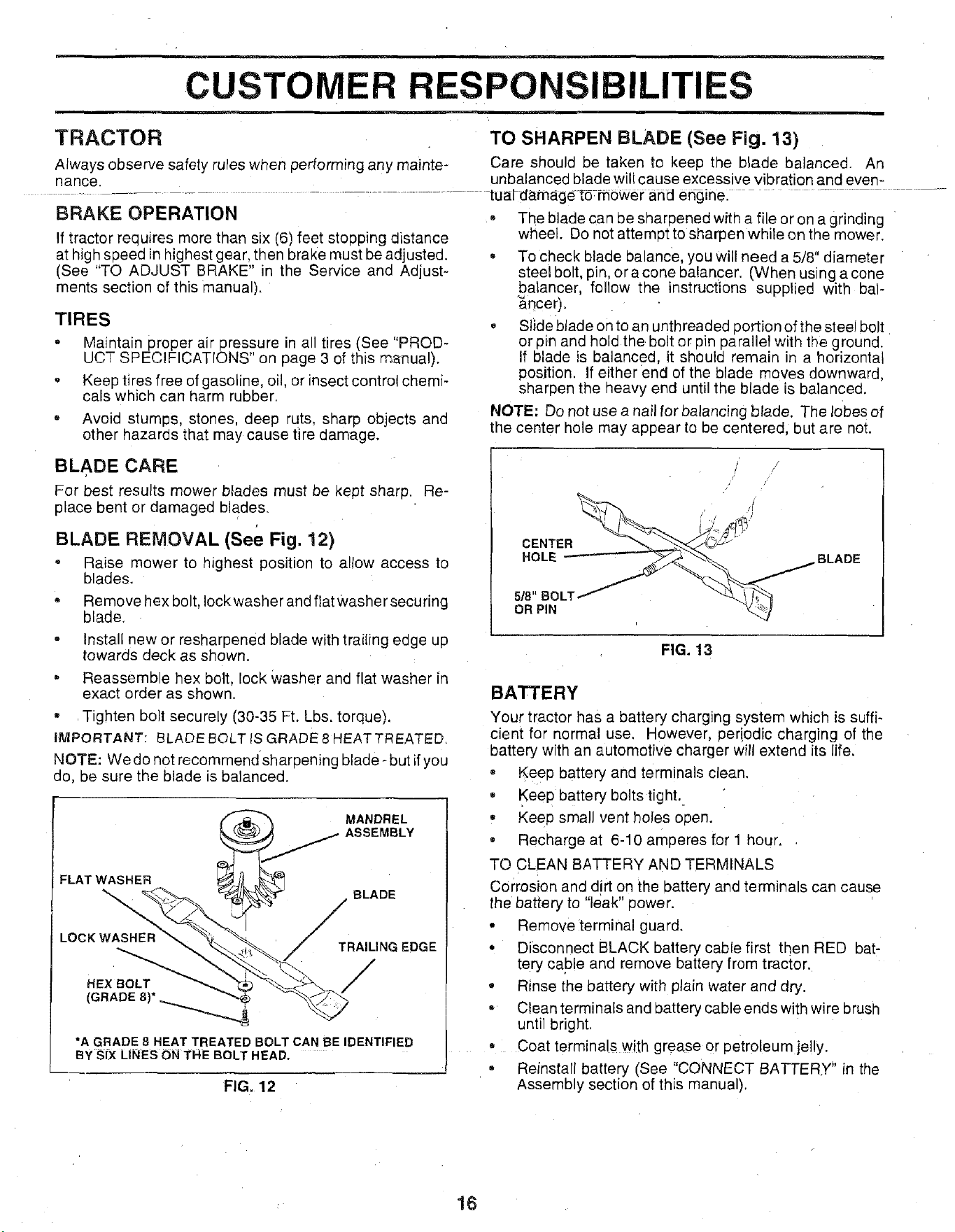
BLADE REMOVAL (See Fig. 12)
Raise mower to highest position to allow access to
blades.
* Remove hex bolt, Iockwasher and flat Washer securing
blade.
- Install new or resharpened blade with trailing eage up
towards deck as shown.
, Reassemble hex bolt, lock washer ane flat washer in
exact order as shown.
, Tighten bolt securely (30-35 Ft. Lbs. torque).
IMPORTANT: BLADE BOLT IS GRADE 8 HEATTREATED.
NOTE: We do not recommend sharpening blade -but if you
do, be sure the blade s balanced.
MANDREL
ASSEMBLY
FLAT WASHER
BLADE
/
LOCK WASHER
TRAILING EDGE
HEX BOLT /
(GRADE 8)* _
*A GRADE 8 HEAT TREATED BOLT CAN BE IDENTIFIED
BY SIX LINES ON THE BOLT HEAD,
FIG. 12
, The blade can be sharpened with a file or on a grinding
wheel. Do not attempt to sharpen while on the mower.
* To check blade balance, you will need a 5/8" diameter
steel bolt, pin, or a cone balancer. (When using a cone
balancer, follow the instructions supplied with bal-
_ncer).
, Slide blade on to an unthreaded portion of the steeJ bolt
or pin and hold the bolt or pin parallet with the ground.
If blade is balanced, it should remain in a horizontal
position. If either end of the blade moves downward,
sharpen the heavy end until the blade is balanced.
NOTE: Do not use a nail for balancing blade. The lobes of
the center hole may appear to be centered, but are not.
CENTER
HOLE BLADE
5/8" B(
OR PIN
FIG. 13
BATTERY
Your tractor has a battery charging system which is suffi-
cient for normal use. However, oeriodic charging of the
battery with an automotive charger will extend its life.
• Keep battery and terminals clean.
• Keep battery bolts tight..
• Keep small vent holes open.
• Recharge at 6-10 amperes for 1 hour.
TO CLEAN BATTERY AND TERMINALS
Corrosion and dirt on the battery and termina s can cause
the battery to "leak" oower.
• Remove terminal guard.
° Disconnect BLACK battery cable first then RED bat-
tery cable and remove battery from tractor.
• Rinse the battery with plain water and dry.
- Clean terminals and battery cable ends with wire brush
until bright.
• Coat terminals with grease or petroleum jelly.
- Reinstall battery (See "CONNECT BATTERY" in the
Assembly section of this manual).
16
CUSTOMER RESPONSIBILITIES
V-BELTS
Check V-be'ts for deterioration and wear after 100 hours of OIL
DRAIN
operation and replace if necessary. The belts are not PLUG
adjustable. Replace belts if they begin to slip from wear.
TRANSAXLE COOLING
Keep transaxle free from build-up of dirt and chaff which
can restrict cooling.
ENGINE
LUBRICATION
Only use high quality detergent oil rated with API service
classification SF or SG. Select the oil's SAE viscosity
grace according to your expected operating temperature.
ENGINEOIL
DIPSTICK AND
FILLTUBE
SAE VISCOSITY GRADES
.20 o 0_ 30 ° 32 ° 40 ° 6U° 80 ° 100 °
TEMPERATURE_NGE AN- CIPATE-_-_L C_E J
AIR SCREEN
FIG. 14
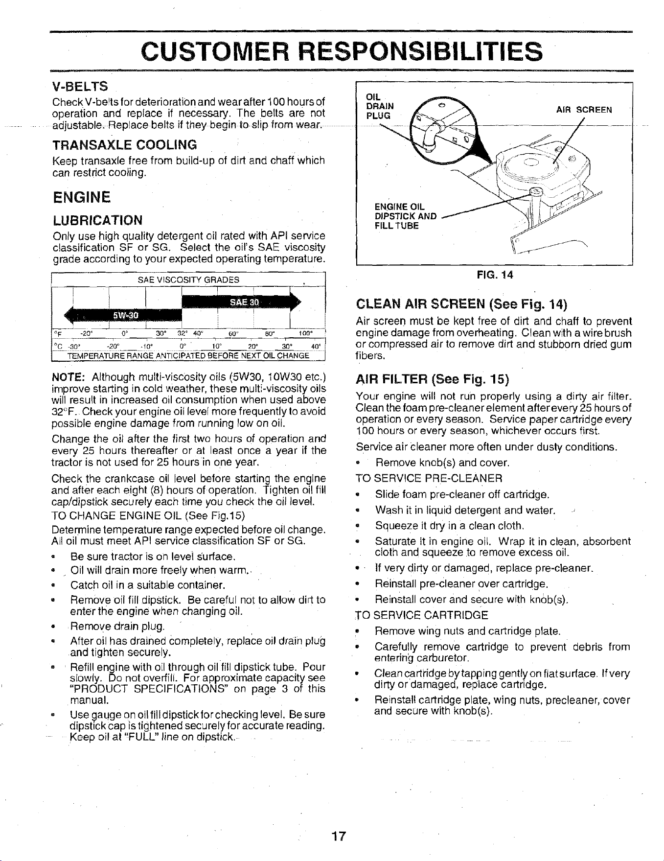
CLEAN AIR SCREEN (See Fig. 14)
Air screen must be kept free of dirt and chaff to prevent
engine damage from overheating. Clean with a wire brush
or compressed air to remove dirt and stubborn dried gum
fibers.
NOTE: Although multi-viscosity oils t5W30, 10W30 etc.)
improve starting in cold weather, these multi-viscosity oils
will result in increased oil consumption when used above
32°F. Check your engine oil level more frequently to avoid
possible engine damage from running low on oil.
Change the oil after the first two hours of operation and
every 25 hours thereafter or at least once a year if the
tractor is not used for 25 hours in one year.
Check the crankcase oil level before starting the engine
and after each eight (8) hours of operation. Tighten oil fill
cap/dipstick securely each time you check the oil level.
TO CHANGE ENGINE OIL (See Fig.15)
Determine temperature range expected before oil change.
All oil must meet API service classification SF or SG.
* Be sure tractor is on level ._urface.
° . Oil will drain more freely when warm..
, Catch oil in a suitable container.
, Remove oil fill dipstick. Be careful not to allow dirt to
enter the engine when changing oil.
= Remove drain plug.
= After oil has drained Completely, replace oil drain plug
and tighten securely.
- Refill engine with oil through oil fill dipstick tube. Pour
slowly. Do not overfill. For approximate capacity see
"PRODUCT SPECIFICATIONS" on page 3 of this
manual.
- Use gauge on oil fill dipsticktor checking level. Be sure
dipstick cap is tightened securely for accurate reading.
Keep oil at "FULL" line on dipstick.
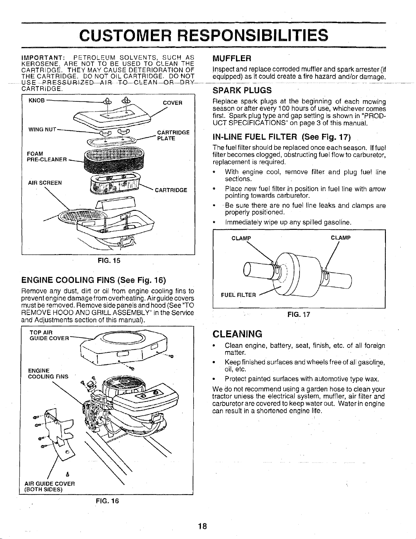
AIR FILTER (See Fig, 15)
Your engine will not run properly using a dirty air filter.
Clean the foam pre-cleaner element afterevery 25 hours of
operation or every season. Service paper cartridge every
100 hours or every season, whichever occurs first.
Service air Cleaner more often under dusty conditions.
° Remove knob(s) and cover.
TO SERVICE PRE-CLEANER
° Slide foam pro-cleaner off cartridge.
• Wash it in liquid detergent and water.
, Squeeze it dry in a clean cloth.
,, Saturate it _nengine oil. Wrap it in clean, absorbent
cloth and squeeze to remove excess oil.
,, If very d!rty or damaged, replace pre-cleaner.
• Reinstall pre-cleaner over cartridge.
° Reinstall cover and secure with kn6b(s).
TO SERVICE CARTRIDGE
• Remove wing nuts and cartridge plate.
• Carefully remove cartridge to prevent debris from
entering carburetor.
• Clean qartiidge bytapping gently on flat sudace. If very
dirty or damaged, replace cartridge.
• Reinstall cartridge plate, wing nuts, precleaner, cover
and secure with knob(s).
17
CUSTOMER RESPONSIBILITIES
IMPORTANT: PETROLEUM SOLVENTS, SUCH AS MUFFLER
KEROSENE, ARE NOT TO BE USED TO CLEAN THE
CARTRIDGE. THEY MAY CAUSE DETERIORATION OF Inspect and replace corroded muffierand spark arrester(if
THE CARTRIDGE. DO NOT OiL CARTRIOGE. DO NOT equipped) as it could create a fire hazard and/or damage.
- USE-PRESSUR4ZED AIR TO CLEAN _OR DRY ..........................................
CARTRIDGE.
KNOB
COVER
FOAM
PRE-CLEANER-.....
AIR SCREEN
FIG. 15
ENGINE COOLING FINS (See Fig. 16)
Remove any dust, dirt or oil from engine cooling fins to
prevent engine damage from overheating. Air guide covers
must be removed. Remove side panels and hood (See"'TO
REMOVE HOOD AND GRILL ASSEMBLY" in the Service
and Adjustments section of this manual).
TOP AIR
GUIDE COVE R'-'__
ENGINE
COOLING FiNS "
\
\
&
AIR GUIDE COVER
(BOTH SIDES)
SPARK PLUGS
Replace spark plugs at the beginning of each mowing
season or after every 100 hours of use, whichever comes
first. Spark plug type and gap setting is shown in "PROD-
UCT SPECIFICATIONS" on page 3 of this manual.
IN-LINE FUEL FILTER (See Fig. 17)
The fuel filter should be replaced once each season. If fuel
filter becomes clogged, obstructing fuel flow to carburetor,
replacement is required.
• With engine cool, remove filter and plug fuel line
sections.
. Place new fuel filter in position in fuel line with arrow
pointing towards carburetor.
• •Be sure there are no fuel line leaks and clamps are
properly positioned.
, Immediately wipe up any spilled gasoline.
CLAMP CLAMP
FuEL FILTER
FIG. 17
CLEANING
• Clean engine, battery, seat, finish, etc. of al! foreign
matter.
• Keep finished surfaces and wheels free of all gasoline,
oil, etc.
• Protect painted surfaces with automotive type wax.
We do not recommend using a garden hose to clean your
tractor unless the electrical system, muffler, air filter and
carburetor are covered to keep water out. Water in engine
can result in a shortened engine life.
FIG. 16
18
m
SERVICE AND ADJUSTMENTS
m
CAUTION: BEFORE PERFORMING ANY SERVICE OR ADJUSTMENTS:
= Depress clutch/brake pedal fully and set parking brake,
- Place gearshift lever in neutral (N) position.
Piace attachment Clutch in "DISENGAGED" position. ..........................
= Turn ignition key "OFF" and remove key,
= Make sure the blades and all moving parts have completely stopped.
• Disconnect spark plug wire from spark plug and place wire where it cannot come in contact with
plug.
TRACTOR
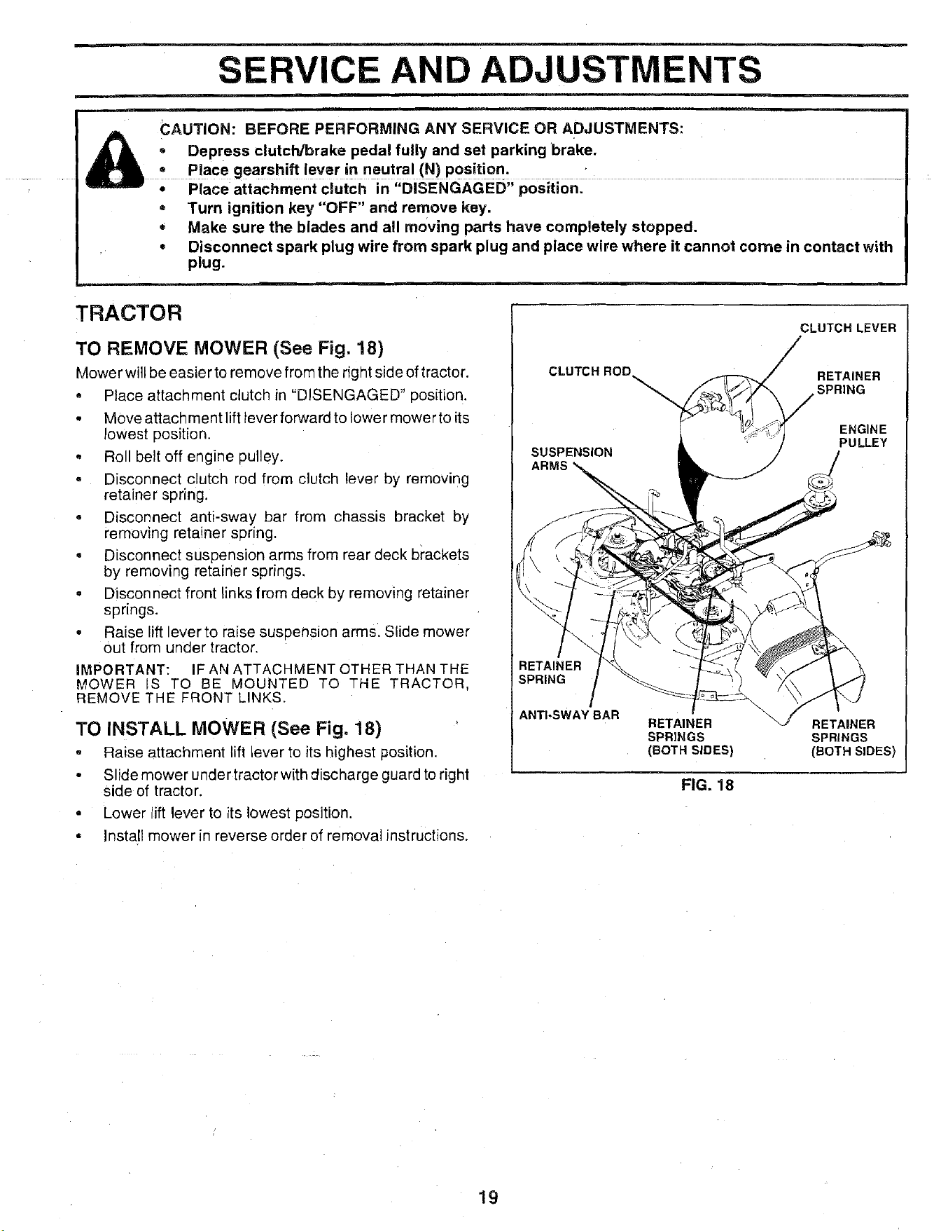
TO REMOVE MOWER (See Fig. 18)
Mower will be easier to remove from the right side of tractor.
, Place attachment clutch in "DISENGAGED" position.
• Move attachment lift lever forward to Iower mower to its
lowest position.
• Roll belt off engine pulley.
, Disconnect clutch rod from clutch lever by removing
retainer spring.
° Disconnect anti-sway bar from chassis bracket by
removing retainer spnng.
• Disconnect suspension arms from rear deck brackets
by removing retainer springs.
= Disconnect front links from deck by removing retainer
springs.
• Raise lift lever to raise susoenslon arms. Slide mower
out from under tractor.
IMPORTANT: F AN ATTACHMENT OTHER THAN THE
MOWER S TO BE MOUNTED TO THE TRACTOR.
REMOVE THE ;RONT LINKS.
TO INSTALL MOWER (See Fig. 18)
- Raise attachment lift lever to its highest position.
• Slidemower undertractorwith discharge guardto right
Side of tractor.
- Lower ift lever to its lowest position.
° Install mower in reverse order of removal instructions.
CLUTCH LEVER
CLUTCH ROD
RETAINER
SPRING
SUSPENSION
ARMS
ENGINE
PULLEY
RETAINER
SPRING I
/
ANTI-SWAY BAR
RETAINER RETAINER
SPRINGS SPRINGS
(BOTH SIDES) (BOTH SIDES)
FIG. 18
19
SERVICE AND ADJUSTMENTS
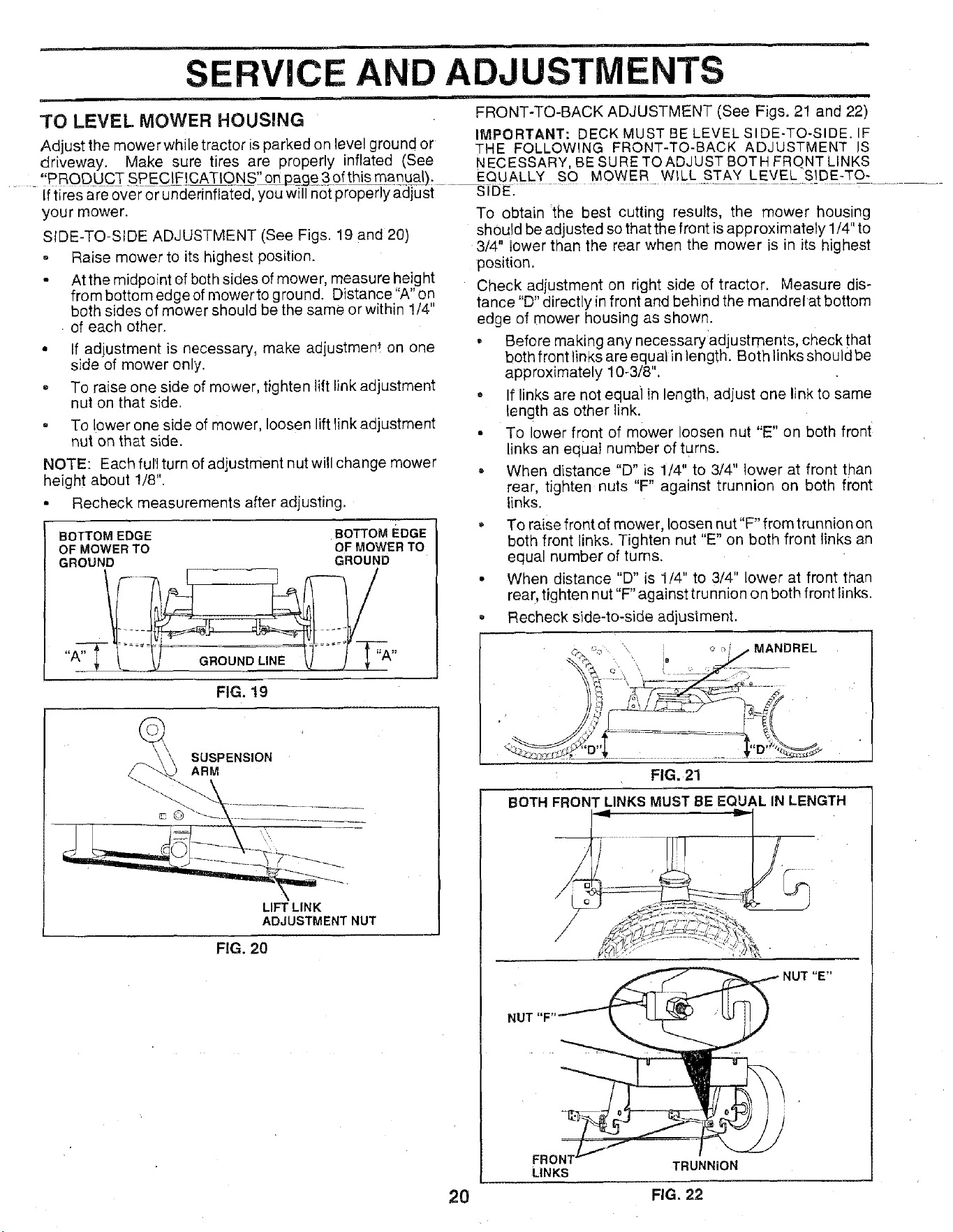
3"0 LEVEL MOWER HOUSING FRONT-TO-BACK ADJUSTMENT (See Figs. 21 and 22)
IMPORTANT: DECK MUST BE LEVEL SIDE-TO,SIDE. IF
Adjustthemowerwhiletractorisparkedonlevelgroundor THE FOLLOWING FRONT-TO-BACK ADJUSTMENT JS
driveway. Make sure tires are properly inflated (See NECESSARY, BESURETOADJUSTBOTHFRONTLINKS
, PRODUCT SPEC[F!CATIONS" o_age.3_pfthis manual) ..... _I_UEALLy SO MOWER WtLL._._TA_Y_L_EV_E_L_S]D.E:_9-
- if tires are over or underinflated, you will not properly acl]-ust S .
your mower. To obtain the best cutting results, the mower housing
SIDE-TO-SI DE ADJUSTMENT (See Figs. 19 and 20) should be adjusted so that the front is approximately 1/4" to
3/4" lower than the rear when the mower is in its highest
= Raise mower to its highest position.
o Atthe midpoint of both sides of mower, measure height
from bottom edge of mowerto ground. Distance "A" on
both sides of mower should be the same or within 1/4"
of each other.
• If adjustment is necessary, make adiustment on one
side of mower only.
To raise one side of mower, tighten lift link adjustment
nut on that side.
- To lower one side of mower, loosen lift link adjustment
nut on that side.
NOTE: Each full turn of adjustment nut will change mower
height about 1/8".
• Recheck measurements after adjusting.
BOTTOM EDGE BOTTOM EDGE
OF MOWER TO OF MOWER TO
GROUND GROUND
FIG. 19
LIFT LINK
ADJUSTMENT NUT
SUSPENSION
ARM
position.
Check adjustment on right side of tractor. Measure dis-
tance "D" directly in front and behind the mandrel at bottom
edge of mower housing as shown.
• Before making any necessaryadjustments, check that
both front links are equat in length. Both links should be
approximately 10-3/8".
= If links are not equai in length, adjust one link to same
length as other link.
• To lower front of mower loosen nut "E" on both front
links an equal number of turns.
When distance "D" is 1/4" to 314" lower at front than
rear, tighten nuts "F" against trunnion on both front
links.
• To raise front of mower, loosen nut"F" from trunnion on
both front links. Tighten nut "E" on both front links an
equal number of tUrns.
• When distance "D" is 1/4" to 3/4" lower at front than
rear, tighten nut "F" against trunnion on both front links.
o Recheck side-to-side adjustment.
FIG. 20
' _ " i o o//MANDREL
FIG. 21
BOTH FRONT LINKS MUST BE EQUAL IN LENGTH
. _ NUT "E"
LINKS TRUNNION
20 FIG. 22
SERVICE AND ADJUSTMENTS
u
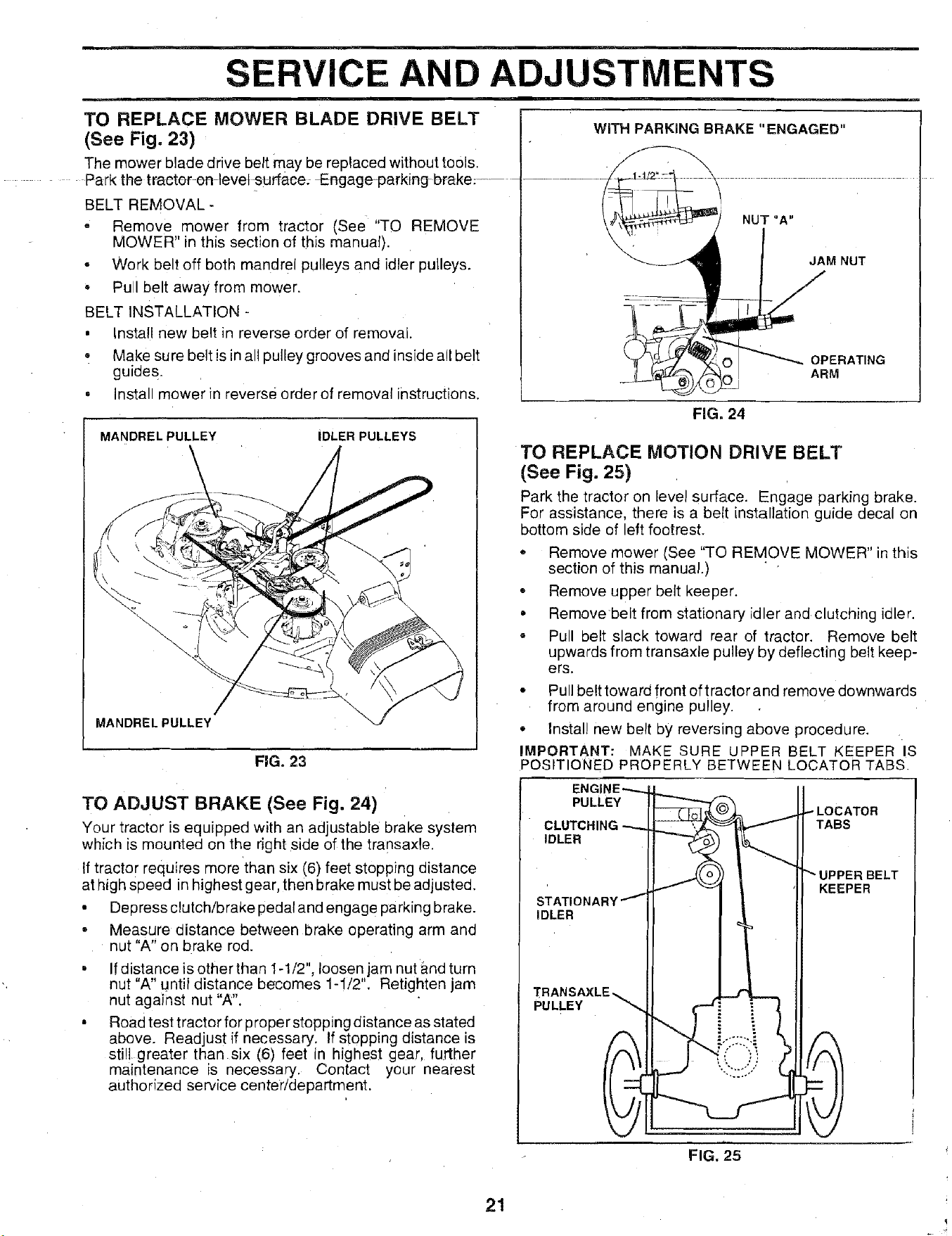
TO REPLACE MOWER BLADE DRIVE BELT
(See Fig. 23)
The mower blade drive belt may be replaced without tools.
Park the tractor-en-levet surface_ Engage13arking brake_......
BELT REMOVAL -
• Remove mower from tractor (See "TO REMOVE
MOWER" in this section of this manual).
• Work belt off both mandrel pulleys and idler pulleys.
• Pull belt away from mower.
BELT INSTALLATION -
, Install new belt in reverse order of removal.
• Make sure belt is in all pulley grooves and inside all belt
guides.
• Install mower in reverse order of removal instructions.
MANDRELPULLEY
IDLER PULLEYS
/
MANDREL PULLEY
FIG. 23
m
WiTH PARKING BRAKE "ENGAGED"
NUT "A"
JAM NUT
OPERATING
ARM
FIG. 24
TO REPLACE MOTION DRIVE BELT
(See Fig. 25)
Park the tractor on level surface. Engage parking brake.
For assistance, there is a belt installation guide decal on
bottom side of left footrest.
Remove mower (See "TO REMOVE MOWER" in this
section of this manual.)
• Remove upper belt keeper.
• Remove belt from stationary idler and clutching idler.
• Pull belt slack toward rear of tractor. Remove belt
upwards from transa×le pulley by deflecting belt keep-
ers.
* Pull belt toward front of tractor and remove downwards
from around engine pulley.
, Install new belt by reversing above procedure.
IMPORTANT: MAKE SURE UPPER BELT KEEPER IS
POSITIONED PROPERLY BETWEEN LOCATOR TABS.
TO ADJUST BRAKE (See Fig. 24)
Your tractor is equipped with an adjustable brake system
which is mounted on the right side of the transaxle.
If tractor requires more than six (6) feet stopping distance
at high speed in highest gear, then brake must be adjusted.
• Depress clutch/brake pedal and engage parking brake.
• Measure distance between brake operating arm and
nut "A" on brake rod.
Ifdistance is other than 1-1/2", loosen jam nut and turn
nut "A" until distance becomes 1-1/2". Retighten jam
nut against nut "A".
Road test tractor for proper stopping distance as stated
above. Readjust if necessary. If stopping distance is
still greater than six (6) feet in highest gear, further
maintenance is necessary. Contact your nearest
authorized service center/department.
PULLEY
CLUTCHING
IDLER
STATIONA
IDLER
TRI
PULLEY
LOCATOR
KEEPER
FIG, 125
21
SERVICE AND ADJUSTMENTS
TO ADJUST STEERING WHEEL ALIGNMENT
If steering wheel crossbars are not horizontal (left to right)
when wheels are positioned straight forward, remove steer-
ing wheeland reassemble per instructiensin-the Assembly
section of this manual.
FRONT WHEEL TOE-IN/CAMBER
The front wheel toe-in and camber are not adjustable on
your tractor. If damage has occurred to affect the front
wheel toe-in or camber, contact your nearest authorized
service center.
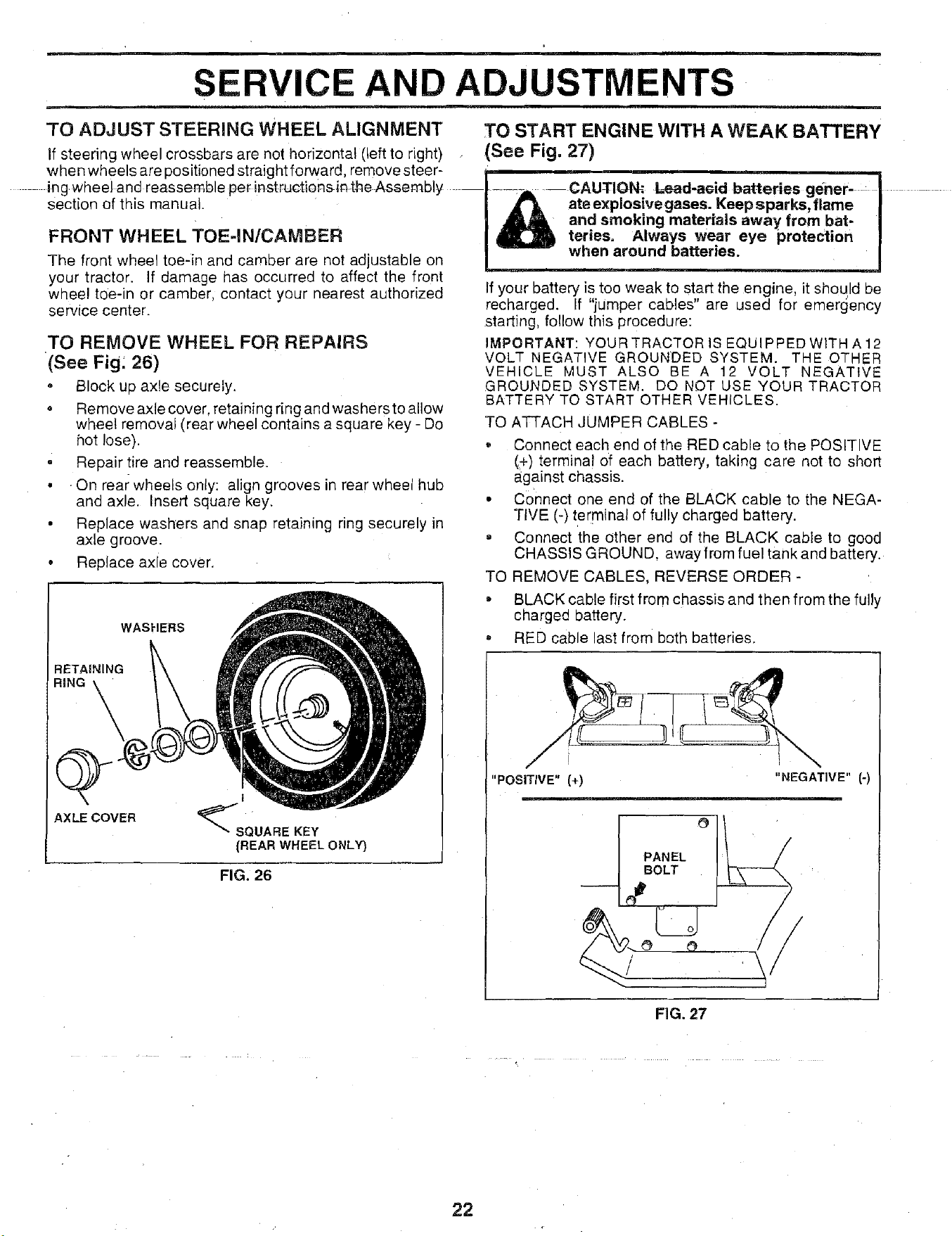
TO REMOVE WHEEL FOR REPAIRS
(See Fig: 26)
° Block up axle securely.
Remove axle cover, retaining ring and washers to allow
wheel removal (rear wheel contains a square key - Do
hot lose).
• Repair tire and reassemble.
• . On rear wheels only: align grooves in rear wheel hub
and axle. Insert square key.
• Replace washers and snap retaining ring securely in
axle groove.
• Replace axle cover.
WASHERS
RETAINING
RiNG
AXLE COVER
I
%SOOAREKEY
(REAR WHEEL ONLY}
FIG. 26
TO START ENGINE WITH A WEAK BATTERY
(See Fig. 27)
....._, -- CAUTION: Lead-a¢id batteries gener ...... J...............
,_ ate explosive gases. Keep sparks, flame J
_1_ and smoking materials away from bat- J
teries. Always wear eye protection J
when around batteries.
your battery is too weak to start the engine, it should be
recharged. If "jUmper cables" are used for emergency
starting, follow this procedure:
IMPORTANT: YOUR TRACTOR IS EQUIPPEDWITH A 12
VOLT NEGATIVE GROUNDED SYSTEM. THE OTHER
VEHICLE MUST ALSO BE A 12 VOLT NEGATIVE
GROU.NDED SYSTEM. DO NOT USE YOUR TRACTOR
BATTERY TO START OTHER VEHICLES.
TO ATTACH JUMPER CABLES -
• Connect each end of the RED cable to the POSITIVE
(.4-)terminal of each battery, taking care not to short
against chassis.
• Connect one end of the BLACK cable to the NEGA-
TIVE (-) terminal of fully charged battery.
= Connect the ether end of the BLACK cable to good
CHASSIS GROUND, away from fuel tank and battery.
TO REMOVE CABLES, REVERSE ORDER -
• BLACK cable first from chassis and then from the fully
charged battery.
= RED cable last from both batteries.
"POSITIVE" (+)
PANEL
BOLT
"NEGATIVE" (-)
\
FIG. 27
22
SERVICE AND ADJUSTMENTS
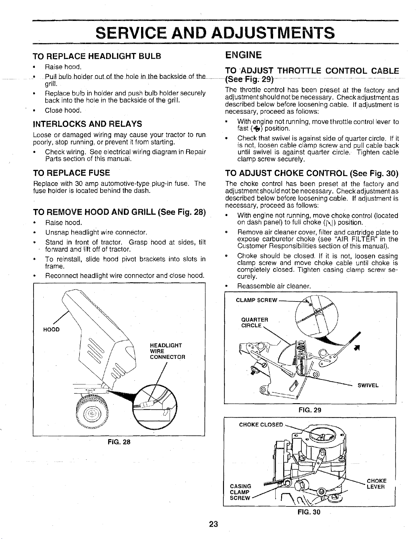
TO REPLACE HEADLIGHT BULB ENGINE
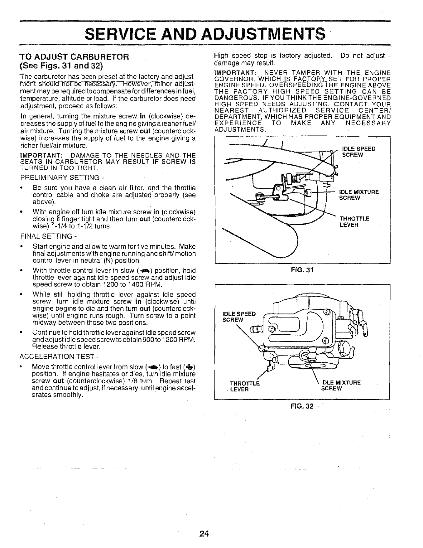
• Raise hood. TO 'ADJUST THROTTLE CONTROL CABLE
• Pull bulb holder out of the hole in the backside of the............(SeeFig• 29) ...........................................
grill.
The throttle control has been preset at the factory and
• Replace bulb in holder and push bulb holder securely
back into the hole in the backside of the grill.
• Close hood.
INTERLOCKS AND RELAYS
Loose or damaged wiring may cause your tractor to run
poorly, stop running, or prevent it from starting.
• Check wiring. See electrical wiring diagram in Repair
Parts section of this manual.
TO REPLACE FUSE
Replace with 30 amp automotive-type plug-in fuse. The
fuse holder is located behind the dash.
TO REMOVE HOOD AND GRILL (See Fig. 28)
• Raise hood.
• Unsnap headlight wire connector.
• Stand in front of tractor. Grasp hood at sides, tilt
forward and lift off of tractor.
• To reinstall, slide hood pivot brackets into slots in
frame.
• Reconnect headlight wire connector and close hood.
HOOD
HEADLIGHT
WIRE
CONNECTOR
FIG. 28
adjustment should not be necessary. Check adjustment as
described below before loosening cable. If adjustment is
necessary, proceed as follows:
• With engine not running, move throttle control lever to
fast (,_) position.
° Check that swivel is against side of quarter circle. If it
is not, loosen cable clamp screw and pull cable back
until swivel is against quarter circle. Tighten cable
clamp screw securely.
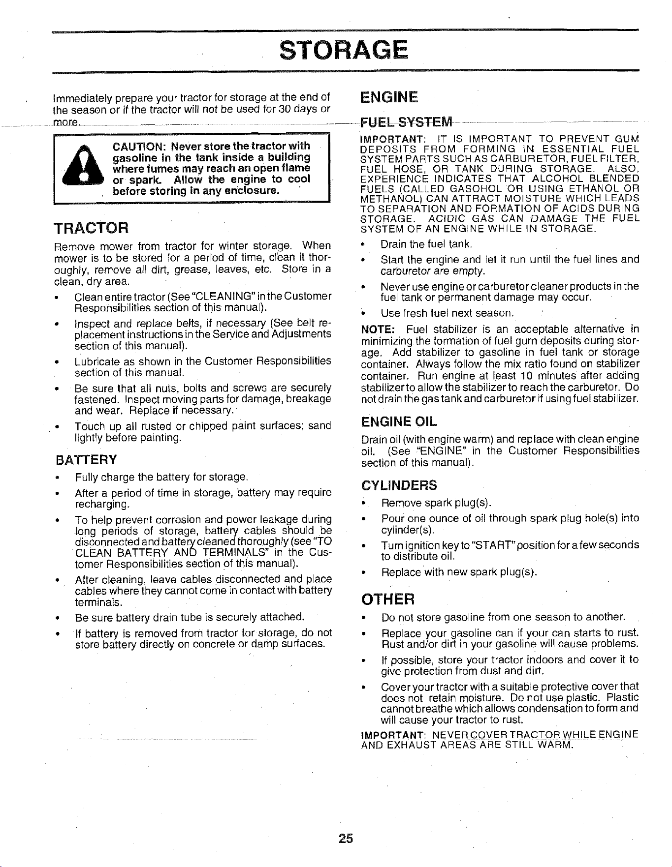
TO ADJUST CHOKE CONTROL (See Fig. 30)
The choke control has been preset at the factory and
adjustment should not be necessary. Check adjustment as
described below before loosening cable. If adjustment is
necessary, proceed as follows:
• With engine not running, move choke control (!ocated
on dash panel) to full choke (IXI) position.
= Remove air cleaner cover, filter and cartridge plate to
expose carburetor choke (see "AIR FILTER" in the
Customer Responsibilities section of this manual).
° Choke should be closed. If it is not, loosen casing
clamp screw and move choke cable until choke is
completely closed. Tighten casing clamp screw se-
curely.
• Reassemble air cleaner.
CLAMP_
QUARTER
CIRCLE
SWIVEL
FIG. 29
CHOKECLOSED
CASING
CLAMP J
SCREW
FIG. 30
CHOKE
LEVER
1
23
SERVICE AND ADJUSTMENTS
TO ADJUST CARBURETOR High speed stop is factory adjusted. Do not adjust -
(See Figs. 31 and 32) damage may result.
IMPORTANT: NEVER TAMPER WITH THE ENGINE
The carburetor has been preset at the factory and adjust- GOVERNOR, WHICH IS FACTORY SET FOR PROPER
f'nent should hot-be nec-esSary._H_eVeC-mlhor _djtJSF .......................................ENGINE SPEED. OVERSPEEDING THE ENGINE ABOVE
ment may be required to compensate for differences in fuel,
temperature, altitude or load. If the carburetor does need
adjustment, proceed as follows:
In general, turning the mixture screw in (clockwise) de-
creases the supply of fuel to the engine giving a leaner fuel/
air mixture. Turning the mixture screw eut (counterclock-
wise) increases the supply of fue! to the engine giving a
richer fuel/air mixture.
IMPORTANT: DAMAGE TO THE NEEDLES A,",tD THE
SEATS IN CARBURETOR MAY RESULT IF SCREW IS
TURNED IN TOO TIGHT.
PRELIMINARY SETTING -
• Be sure you have a clean air filter, and the throttle
control cable and choke are adjusted properly (see
above).
• With engine off turn idle mixture screw in (clockwise)
closing it finger tight and then turn out (counterclock-
wise) 1-1/4 to 1-1/2 turns.
FINAL SETTING -
• Start engine and allow to warm for five minutes. Make
finat adjustments with engine running and shift/motion
control lever in neutral (N) position.
° With throttle control lever in slow (,_) position, hotd
throttle lever against idle speed screw and adjust idle
speed screw to obtain 1200 to 1400 RPM.
• While still holding throttle lever against idle speed
screw, turn idle mixture screw in (clockwise) until
engine begins to die and then turn out (counterclock-
wise) until engine runs rough. Turn screw to a point
midway between those two positions.'
• Continue to hold throttle lever against idle speed screw
and adjust idle speed screw to obtain 900 to 1200 RPM.
Release throttle lever.
ACCELERATION TEST -
Move throttle controt lever from slow (,_) to fast (,_)
position. If engine hesitates or dies, turn idle mixture
screw out (counterclockwise) 1/8 turn. Repeat test
and continue to adjust, if necessary, until engine accel-
erates smoothly.
THE FACTORY HIGH SPEED SETTING CAN BE
DANGEROUS. IFYOU THINKTHE ENGINE-GOVERNED
HIGH SPEED NEEDS ADJUSTING, CONTACT YOUR
NEAREST AUTHORIZED SERVICE CENTER/
DEPARTMENT, WHICH HAS PROPER EQUIPMENT AND
EXPERIENCE TO MAKE ANY NECESSARY
ADJUSTMENTS.
IDLE SPEED
SCREW
IDLE MIXTURE
SCREW
THROTTLE
LEVER
FIG. 31
IDLE SPEED _ _( :_l_
THROTTLE i \ IDLE MIXTURE
LEVER SCREW
FIG. 32
24
STORAGE
immediately prepare your tractorfor storage at the end of ENGINE
the season or if the tractor will not be used for 30 days or
..... mole ................................................. FUEL SYSTEM ...............................
CAUTION: Never store the tractor with
gasoline in the tank inside a building
where fumes may reach an open flame
or spark. Allow the engine to cool
before storing in any enclosure.
TRACTOR
Remove mower from tractor for winter storage. When
mower is to be stored for a period of time, clean it thor-
oughly, remove al! dirt, grease, leaves, etc. Store in a
clean, dry area.
• Clean entire tractor (See"CLEAN ING" in the Customer
Responsibilities section of this manual).
• Inspect and replace belts, if necessary (See belt re-
placement instructions in the Service and Adjustments
section of this manual).
• Lubricate as shown in the Customer Responsibilities
section of this manual.
• Be sure that all nuts; bolts and screws are securely
fastened. Inspect moving parts for damage, breakage
and wear. Replace if necessary.
• Touch up all rusted or chipped paint surfaces; sand
lightTy before painting.
BATTERY
• Fully charge the battery for storage.
• After a period of time in storage, battery may require
recharging.
• To help prevent corrosion and power leakage during
long periods of storage, battery cables should be
disconnected and batterycleaned thoroughly (see "TO
CLEAN BATTERY AND TERMINALS" in the Cus-
tomer Responsibilities section of this manual).
• After cleaning, leave cables disconnected and place
cables where they cannot come in contact with battery
terminals.
• Be sure battery drain tube is securely attached.
• If battery is removed from tractor for storage, do not
store battery directly on concrete or damp surfaces.
iMPORTANT: IT IS IMPORTANT TO PREVENT GUM
DEPOSITS FROM FORMING IN ESSENTIAL FUEL
SYSTEM PARTS SUCH AS CARBURETOR, FUEL FILTER,
FUEL HOSE, OR TANK DURING STORAGE. ALSO,
EXPERIENCE INDICATES THAT ALCOHOL BLENDED
FUELS (CALLED GASOHOL OR USING ETHANOL OR
METHANOL) CAN ATTRACT MOISTURE WHICH LEADS
TO SEPARATION AND FORMATION OF ACIDS DURING
STORAGE. ACIDIC GAS CAN DAMAGE THE FUEL
SYSTEM OF AN ENGINE WHILE IN STORAGE.
• Drain the fuel tank.
• Start the engine and let it run until the fuel lines and
carburetor are empty.
• Never use engine or carburetor cleaner products inthe
fuel tank or permanent damage may occur.
° Use fresh fuel next season.
NOTE: Fuel stabilizer is an acceptable alternative in
minimizing the formation of fuel gum deposits during stor-
age. Add stabilizer to gasoline in fuel tank or storage
container. Always follow the mix ratio found on stabilizer
container. Run engine at least 10 minutes after adding
stabilizer to allow the stabilizer to reach the carburetor. Do
not drain the gas tank and carburetor if using fuel stabilize r.
ENGINE OIL
Drain oil (with engine warm) and replace with clean engine
oil. (See _'ENGINE" in the Customer Responsibilities
section of this manual).
CYLINDERS
' Remove spark plug(s).
• Pour one ounce of oil through spark plug hole(s) into
cylinder(s).
• Turnignitionkeyto"START"positionforafewseconds
to distribute oil.
• Replace with new spark plug(s).
OTHER
• Do not store gasoline from one season to another.
• Replace your gasoline can if your can starts to rust.
Rust and/or dirt in your gasoline will cause problems.
• If possible, store your tractor indoors and cover it to
give protection from dust and dirt.
• Cover your tractor with a suitable protective cover that
does not retain moisture. Do not use plastic. Plastic
cannot breathe which allows condensation to form and
will cause your tractor to rust.
IMPORTANT: NEVERCOVER TRACTQB WH!LE ENG!N E
AND EXHAUST AREAS ARE STILL WARM.
25
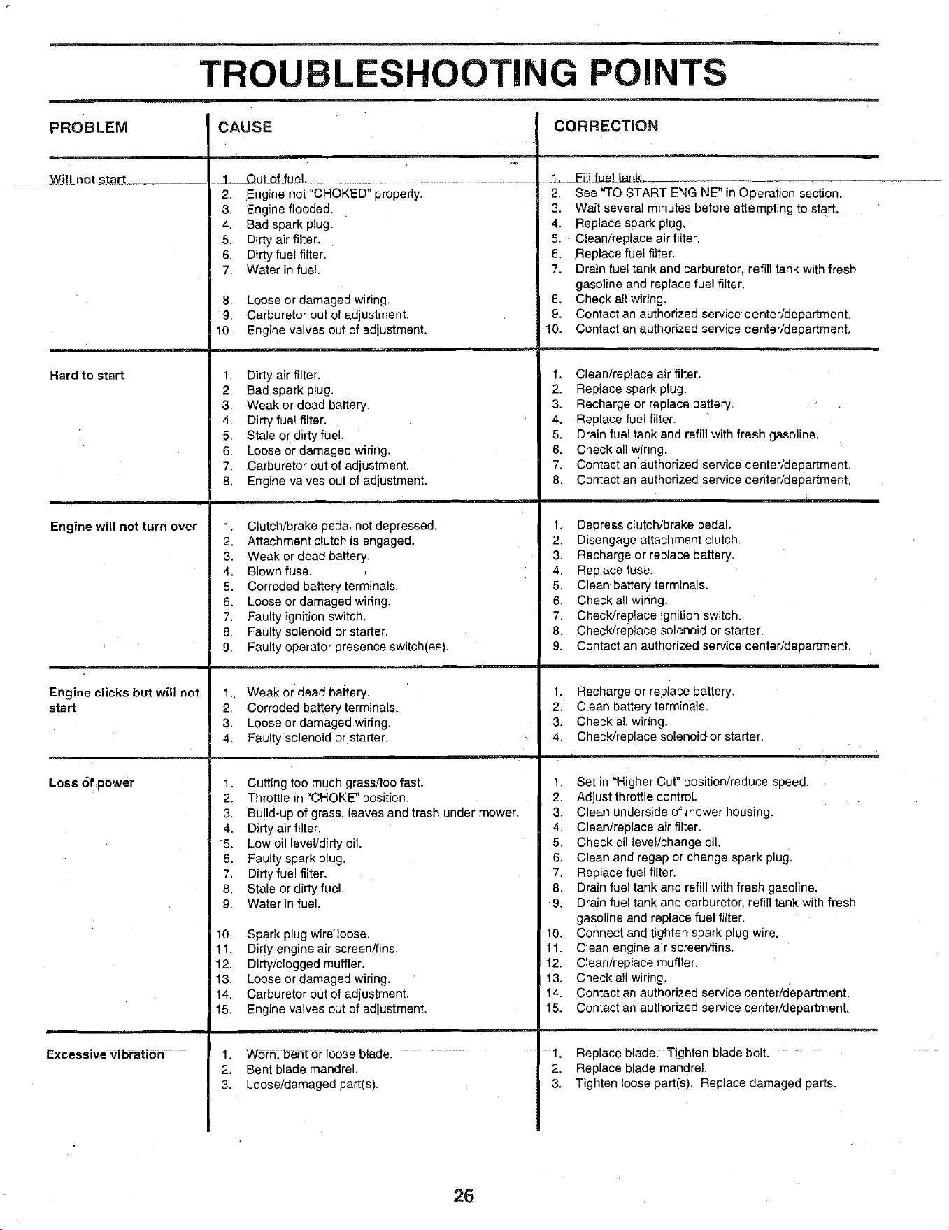
PROBLEM
Wi!Inot _tart ............
TROUBLESHOOTING POINTS
CAUSE CORRECTION
J. _.Out_of _ue].............................. __:ill fueLtaak ....
Hard to start
Engine will not turn over
Engine clicks but will not
start
Loss 6fpower
Excessive vibration
2. Engine not "CHOKED" properly.
3. Engine flooded.
4. Bad spark plug,
5. Dirty air filter.
6. Dirty fuel filter,
7. Waterin fuel.
8. Loose or damaged wiring
9. Carburetor out of adjustment,
10. Engine valves out of adjustment,
1. Dirty air filter.
2, Bad spark plug.
3. Weak or dead battery.
4. Dirty fue! filter,
5. Stale or dirty fuel.
6. Loose or damaged Wiring.
7. Carburetor out of adjustment.
8. Engine valves out of adjustment.
1. Clutch/brake pedal not depressed.
2. Attachment clutch is engaged.
3, Weak or dead battery.
4. Blown fuse.
5, Corroded battery terminals.
6. Loose or damaged wiring.
7. Faulty ignition switch,
8. Faulty solenoid or starter.
9, Faulty operator presence switch(es),
1.. Weak or dead battery.
2. Corroded battery terminals,
3. Loose or damaged wiring.
4. Faulty solenoid or starter.
1. Cutting too much grass!too fast.
2. Throttle in "CHOKE" position.
3. Build-up of grass, leaves and trash under mower.
4. Dirty air filter.
5, Low oil level/dirty oil.
6. Faulty spark plug.
7. Dirty fuel filter.
8. Stale or dirty fuel.
9. Waterin fuel.
10. SPark plug wire'loose,
11. Dirty engine air screen/fins.
12. Dirty/clogged muffler.
13. Loose or damaged widng.
14, Carburetor out of adjustment.
15. Engine valves out of adjustment.
1. Worh, bent or loose blade.
2. Bent blade mandrel.
3. Loose/damaged part(s).
m
2, See "TO START ENGINE" in Operation section.
3. Wait several minutes before attempting to start.
4. Replace spark plug.
5. Clean/replace air filter.
6, Replace fuel filter.
7, Drain fuel tank and carburetor, refill tank with fresh
gasoline and replace fuel filter.
8. Check all wiring.
9, Contact an authorized service center/department,
10, Contact an authorized service center/department.
1. Clean/replace air filter,
2. Replace spark plug.
3. Recharge or replace battery.
4. Replace fuel filter,
5. Drain fuel tank and refill with fresh gasoline.
6. Check all wiring.
7. Contact an'authorized service center/department.
8. Contact an authorized service center/department.
1, Depress clutch/brake pedal.
2. Disengage attachment clutch.
3. Recharge or replace battery.
4. Replace fuse.
5. Clean battery terminals.
6. Check all wiring.
7. ChecWreplace ignition switch.
8. Check/replace solenoid or starter,
9. Contact an authorized service center/department.
1. Recharge or replace battery.
2, Clean battery terminals.
3. Check al! wiring.
4. Check/replace solenoid, or starter.
1. Set in "Higher Cut" position/reduce speed.
2. Adjust throttle control.
3. Clean underside of mower housing.
4. Clean/replace air filter,
5. Check oil leve!/change oil.
6. Clean and regap Or change spark plug.
7, Replace fuel filter.
8. Drain fuel tank and refill with fresh gasoline.
9. Drain fuel tank and carburetor, refill tank with fresh
gasoline and replace fuel filter.
10. Connect and tighten spark plug wire.
11. Clean engine air screen/fins.
12. Clean/replace muffler.
13. Checkall wiring.
14. Contact an authorized service center!department.
15. Contact an authorized service center/department,
1, Replace blade; Tighten blade bolt. '
2. Replace blade mandrel.
& Tighten loose part(s). Replace damaged parts.
26
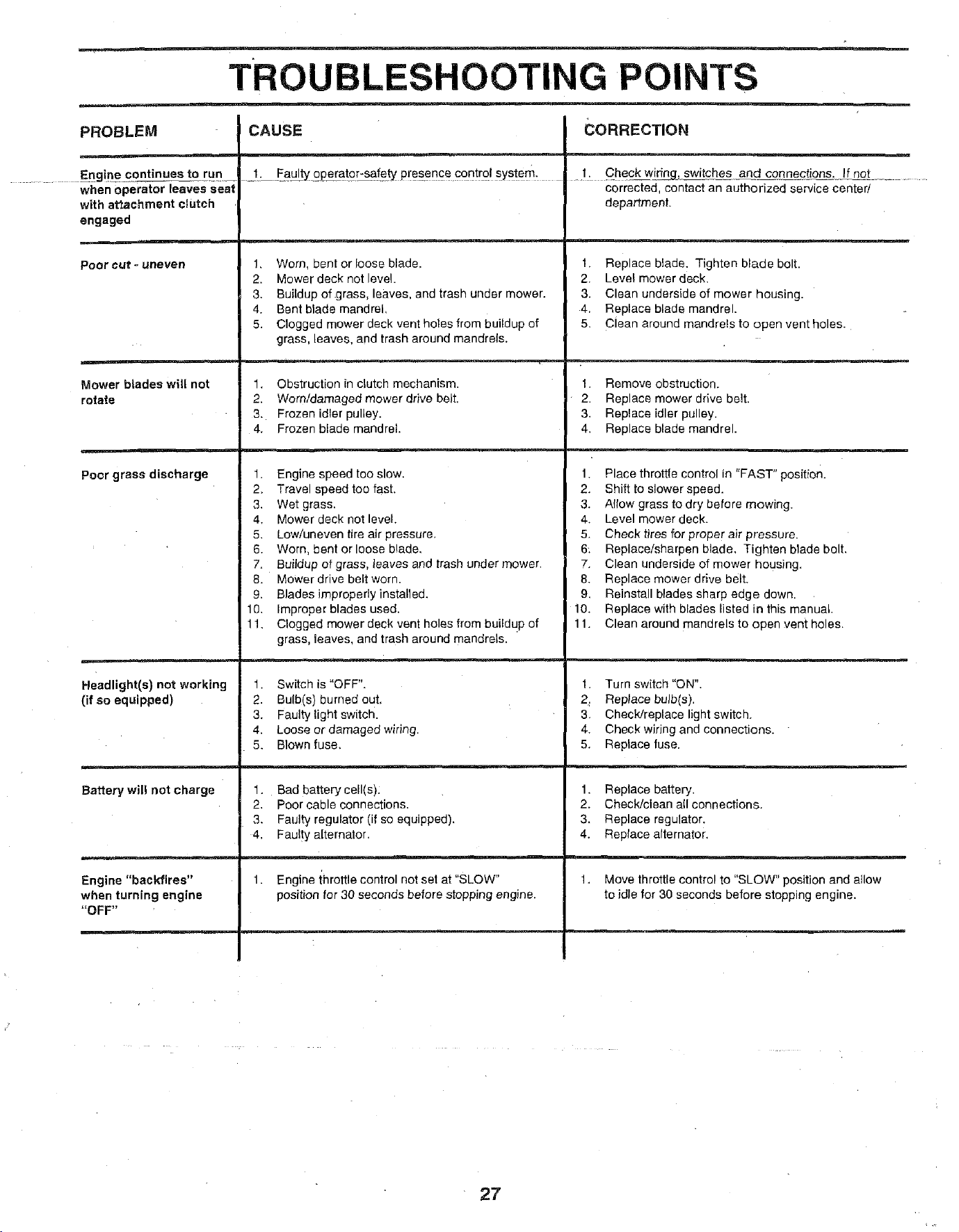
TRO LESHOOTING POINTS
PROBLEM CAUSE CORRECTION
...... Enginecontinuest- __eru n _1. Faul__0Peratgr-sa/etyp[es_encec0ntrg!syste m. t: Cbeckw[ring_switches and connections. If not
when Operator leaves seat
with attachment clutch
engaged
Poorcut-uneven
Mower blades will not
rotate
Poer grass discharge
Headlight(s) not working
(if so equipped)
Battery wil! not charge
Engine "backfires"
when turning engine
"OFF"
1, Worn, bent orloose blade,
2. Mower deck not level.
3. Buildup of grass, leaves, and trash under mower.
4. Bent blade mandrel,
5. Clogged mower deck vent holes from buildup of
grass, leaves, and trash around mandrels.
1, Obstruction in clutch mechanism.
2. Worn/damaged mower drive belt.
3. Frozen idler pulley.
4. Frozen blade mandrel.
1. Engine speed too slow.
2, Travel speed too fast,
3. Wet grass,
4. Mower deck not level.
5. Low/uneven tire air pressure.
6. Worn, bent or loose blade.
7. Buildup of grass, leaves and trash under mower,
8. Mower drive belt worn.
9, Blades improperly installed.
10. Improper blades used.
11. Clogged mower deck vent holes from buildup of
grass, leaves, and trash around mandrels.
1. Switch is "OFF".
2. Bulb(s) burned out,
3. Faulty light switch.
4. Loose or damaged wiring.
5. Blown fuse.
1. Bad battery cell(s):
2. Poor cable connections.
3. Faulty regulator (if so equipped).
4. Faulty alternator.
1. Engine ihrottle control not set at "SLOW"
position for 30 seconds before stopping engine.
corrected, contact an authorized service center/
department.
1. Replace blade. Tighten blade bolt.
2. Level mower deck.
3. Clean underside of mower housing.
4. Replace blade mandrel.
5. Clean around mandrels to open vent holes.
1. Remove obstruction.
2. Replace mower drive belt.
3. Replace idler pulley.
4, Replace blade mandrel.
1. Place throttle control in "FAST" position.
2. Shift to slower speed.
3. Allow grass to dry before mowing.
4. Level mower deck.
5. Check tires for proper air pressure.
6: Replace/sharpen blade, Tighten blade bolt.
7. Clean underside of mower housing.
8. Replace mower drive belt.
9. Reinstall blades sharp edge down.
10. Replace with blades listed in this manual.
11. Clean around mandrels to open vent holes,
1. Turn switch "ON".
2. Replace bulb(s).
3. Check!replace light switch.
4. Check wiring and connections.
5. Replace fuse.
1. Replace battery.
2. Check/clean all connections.
3. Replace regulator.
4. Replace alternator.
1. Move throttle control to "SLOW" position and allow
to idle for 30 seconds before stopping engine.
27

SERVICE NOTES
28
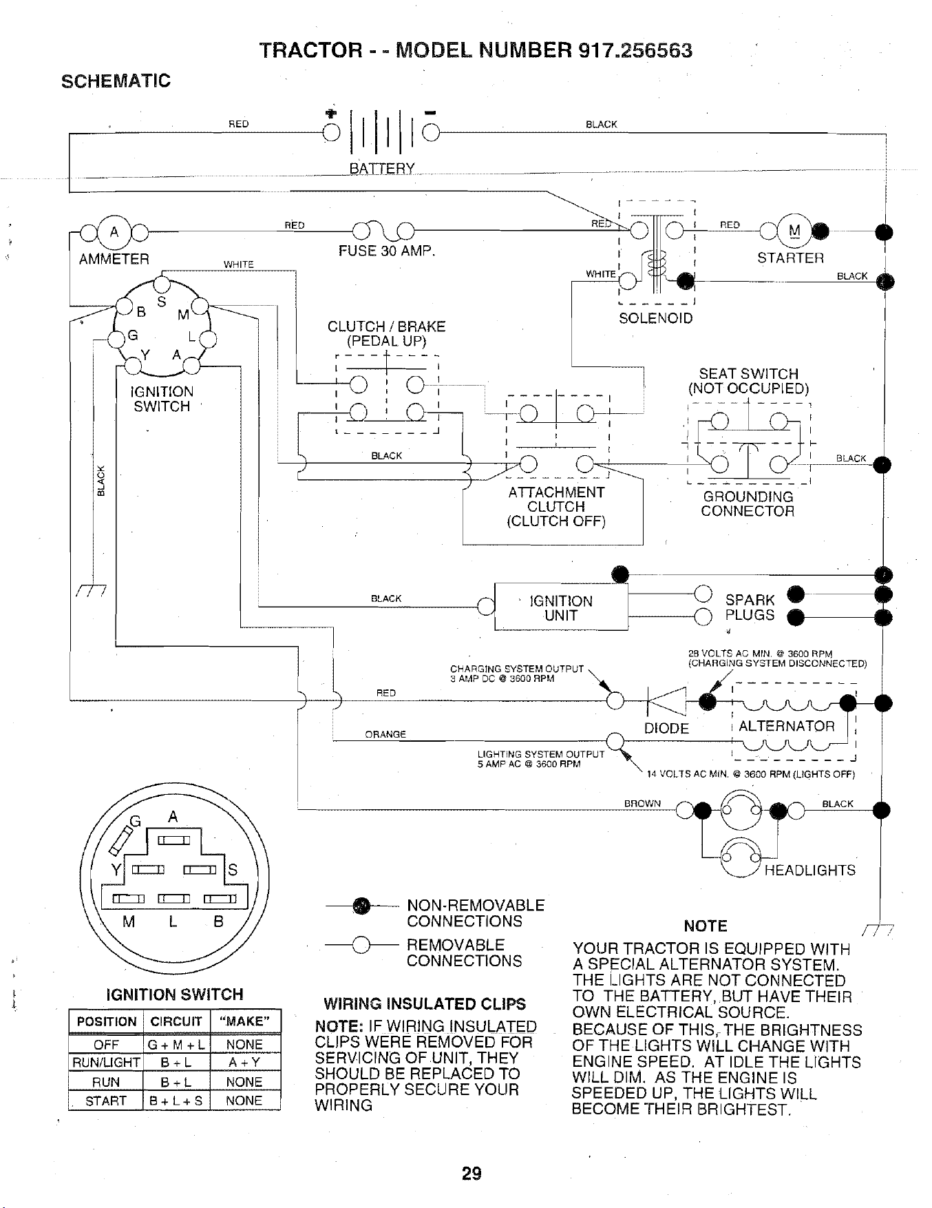
TRACTOR - = MODEL NUMBER 917.256563
SCHEMATIC
RED
o I o
BLACK
......................... B._A_TT.5RY.....................................................
AMMETER
S
G L
IGNITION
SWITCH
WHITE
RED
SEAT SWITCH
(NOT OCCUPIED)
i
GROUNDING
CONNECTOR
t
BLACK IGNITION SPARK
UNIT PLUGS
BLACK O
BLACK
"D
I
qD
qD
28VOLTS AC MIN @ 3600 BP_"
,CHARGING SYSTEM DISCONNECTED)
RED
ORANGE
C HA_C'DIN G@S3Y6SoToERMp_UT P UT "-_ ,___
DIODE iALTERNATORI;
LIGHT,NGSYSTEMOUTPUT(Z_ _-_'-AJ_J-J_
5 AMP AC @ 3600 RPM \
14 VOLTS AC MIN. @ 3600 RPM (UGHTS OFF)
BROWN
_L BLACK
IGHTS
IGNITION SWITCH
POSITION CIRCUIT "MAKE"
OFF G + M + L NONE
RUN/LIGHT B + L A + Y
RUN B + L NONE
START B + L + S NONE
--_ NON-REMOVABLE
CONNECTIONS
O REMOVABLE
CONNECTIONS
WIRING INSULATED CLIPS
NOTE: IF WIRING INSULATED
CLIPS WERE REMOVED FOR
SERVICING OF UNIT, THEY
SHOULD BE REPLACED TO
PROPERLY SECURE YOUR
WIRING
NOTE
YOUR TRACTOR IS EQUIPPED WITH
A SPECIAL ALTERNATOR SYSTEM.
THE LIGHTS ARE NOT CONNECTED
TO THE BATTERY, BUT HAVE THEIR
OWN ELECTRICAL SOURCE.
BECAUSE OF THIS, THE BRIGHTNESS
OF THE LIGHTS WILL CHANGE WITH
ENGINE SPEED. AT IDLE THE LIGHTS
WILL DIM. AS THE ENGINE IS
SPEEDED UP, THE LIGHTS WILL
BECOME THEIR BRIGHTEST.
29
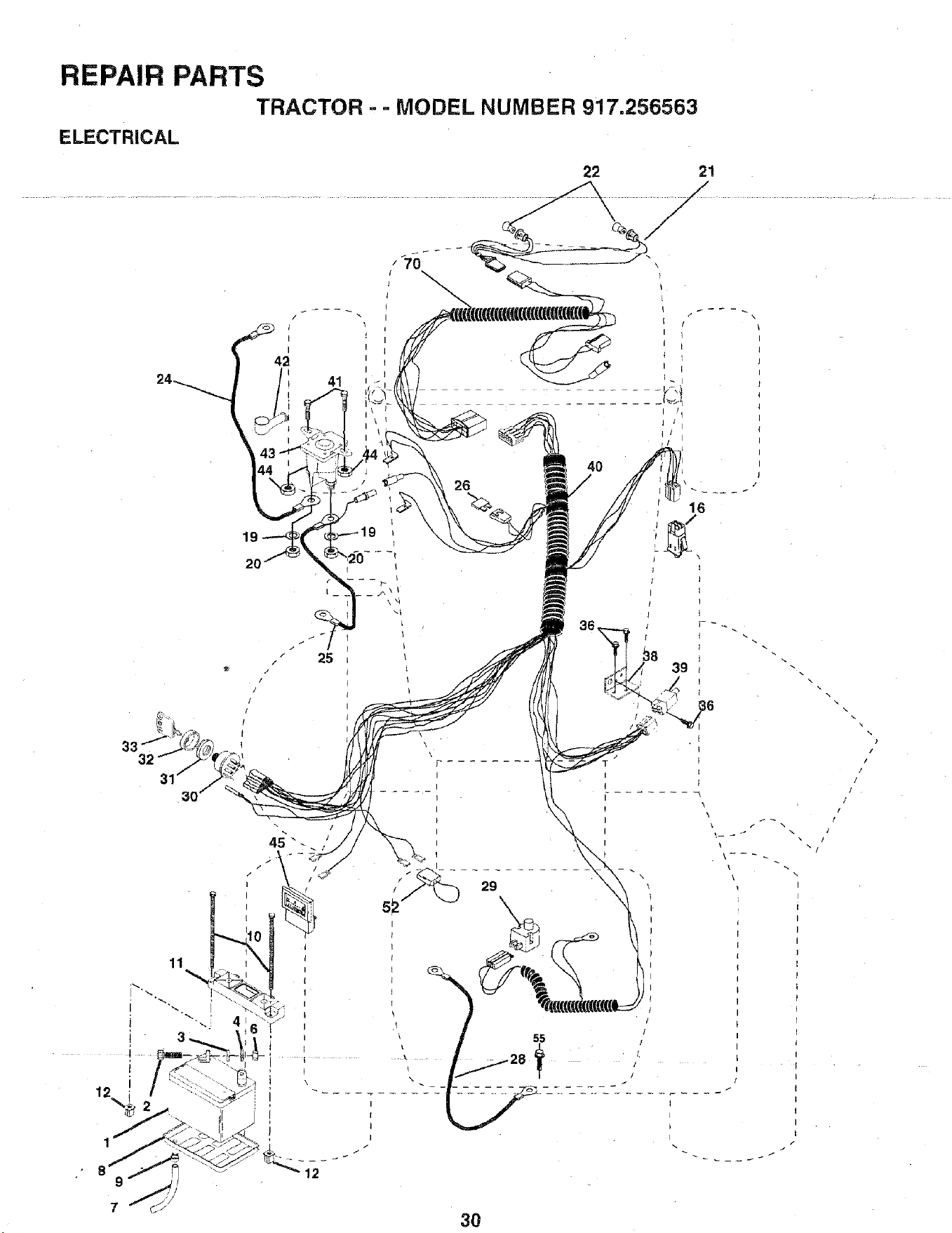
REPAIR PARTS
TRACTOR , - MODEL NUMBER 917.256563
ELECTRICAL
22 21
I
42
41
/
/
]
/
/
I
l
I
26
4O
3O
x ]
\ /
x I
\
\
)
/
I
l
I
]
/
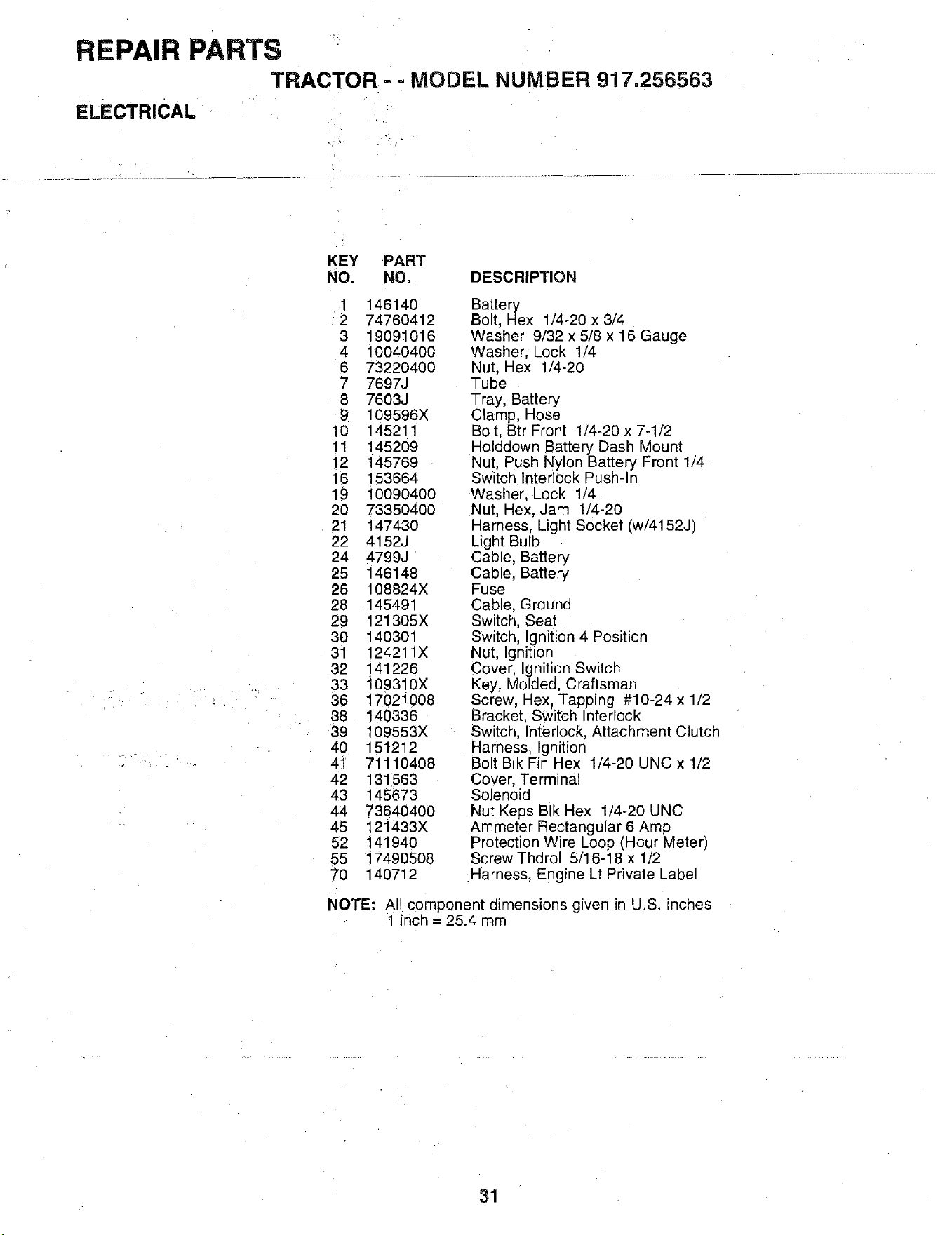
REPAIR PARTS
TRACTOR = = MODEL NUMBER 917.256563
ELECTRICAL
KEY PART
NO. NO, DESCRIPTION
1 146140
2 74760412
3 19091016
4 1OO4O4OO
6 73220400
7 7697J
8 7603J
9 109596X
10 145211
11 145209
12 145769
16 153664
19 10090400
20 73350400
21 147430
22 4152J
24 4799J
25 146148
26 108824X
28 145491
29 121305X
30 140301
31 124211X
32 141226
33 109310X
36 17021008
38 140336
39 109553X
40 151212
41 71110408
42 131563
43 145673
44 73640400
45 121433X
52 141940
55 17490508
70 140712
Battery
Bolt, Hex 1/4-20 x 3/4
Washer 9/32 x 5/8 x 16 Gauge
Washer, Lock 1/4
Nut, Hex 1/4-20
Tube
Tray, Battery
Clamp, Hose
Bolt, Btr Front 1/4-20 x 7-1/2
Holddown Battery Dash Mount
Nut, :_ush Nylon Battery Front 1/4
Switch Interlock Push-In
Washer. Lock 1/4
Nut, Hex, Jam 1/4-20
Harness, Light Socket (w/4152J)
Light Bulb
Cable, Battery
Cable, Battery
Fuse
Cable, Groune
Switch, Seat
Switch, Ignition 4 Position
Nut, Ignition
Cover, Ignition Switch
Key, Molded, Craftsman
Screw, Hex, Tapping #10-24 x 1/2
Bracket, Switch Interlock
Switch, Interlock, Attachment Clutch
Harness, Ignition
Bolt BIk Fin Hex 1/4-20 UNC x 1/2
Cover, Terminal
Solenoid
Nut Keps BIk Hex 1/4-20 UNC
Ammeter Rectangular 6 Am p
Protection Wire Loop (Hour Meter)
ScrewThdrol 5/16-18 x 1/2
Harness, Engine Lt Private Label
NOTE: AI component dimensions given in U.S. inches
1 inch = 25.4 mm
31
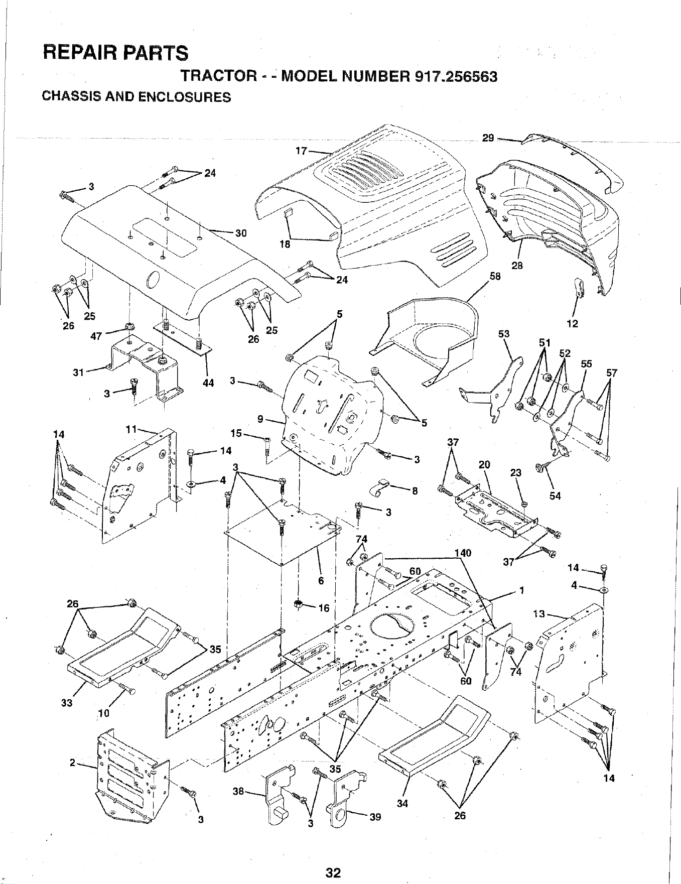
REPAIR PARTS
TRACTOR - MODEL NUMBER 917,256563
CHASSIS AND ENCLOSURES
\J
/
I
26
47
14
26
33
<10
25
26
18
6
28
58
' 12
53
60
34
26
14
32
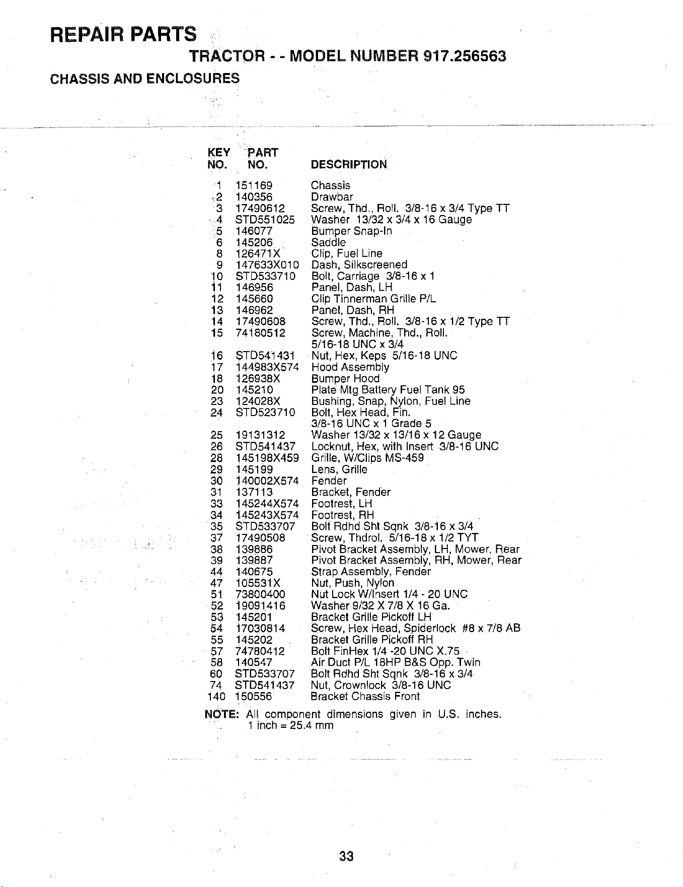
REPAIR PARTS
TRACTOR - - MODEL NUMBER 917.256563
CHASSIS AND ENCLOSURES
KEY PART
NO. NO. DESCRIPTION
1 151169
42 140356
3 17490612
4 STD551025
5 146077
6 145206
8 126471X
9 147633X010
!0 STD533710
11 146956
12 145660
13 146962
14 17490608
15 74180512
16 STD541431
17 144983X574
18 126938X
20 145210
23 124028X
24 STD523710
25 19131312
26 STD541437
28 145198X459
29 145199
30 140002X574
31 137113
33 145244X574
34 145243X574
35 STD533707
37 17490508
38 139886
39 139887
44 140675
47 105531X
51 73800400
52 19091416
53 145201
54 17030814
55 145202
57 74780412
58 140547
60 STD533707
74 STD541437
140 150556
Chassis
Drawbar
Screw, Thd., RoTI. 3/8-16 x 3/4 Type TT
Washer 13/32 x 3/4 x 16 Gauge
Bumper Snap-In
Saddle
Clip, Fuel Line
Dash, Silkscreened
Bolt Carriage 3/8-16 x 1
Panel, Dash, LH
Clip Tinne rman Grille P/L
Panel, Dash, RH
Screw, Thd.. Roll. 3/8-16 x 1/2 Type TT
Screw, Machine. Thd., Roll.
5/16-18 UNC x 3/4.
Nut, Hex, Keps 5/16-18 UNC
Hood Assemb y
Bumper Hood
Plate Mtg Battery Fue Tank 95
Bushing, Snap, Nylon, Fuel Line
Bolt, Hex Head. Fin.
3/8-16 UNC x 1 Grade 5
Washer 13/32 x 13/16 x 12 Gauge
Locknut, Hex, with nsert 3/8-16 UNC
Grille. W/Clips MS-459
Lens. Grille
Fender
Bracket, Fender
Footrest, LH
Footrest, RH
Bolt Rdhd Sht Sqnk 3/8-16 x 3/4
Screw, Thdrol. 5/16-18 x 1/2 TYT
Pivot Bracket Assembly, LH, Mower. Rear
Pivot Bracket Assembly, RH, Mower, Rear
Strap Assembly, Fender
Nut. Push, Nylon
Nut Lock W/Insert 1/4 - 20 UNC
Washer 9/32 X 7/8 X 16 Ga.
Bracket Grille Pickoff LH
Screw. Hex Head Soiderlock #8 x 7/8 AB
Bracket Grille Pickoff RH
Bolt FinHex 1/4 -20 UNC X.75
Air Duct P/L 18HP B&S Opp. Twin
Bolt Rdhd Sht Sqnk 3/8-16 x 3/4
Nut, Crownlock 3/8-16 UNC
Bracket Chassis Front
NOTE: A com_x)nent dimensions given Jr" U.S. inches.
1 inch = 25. Amm
33
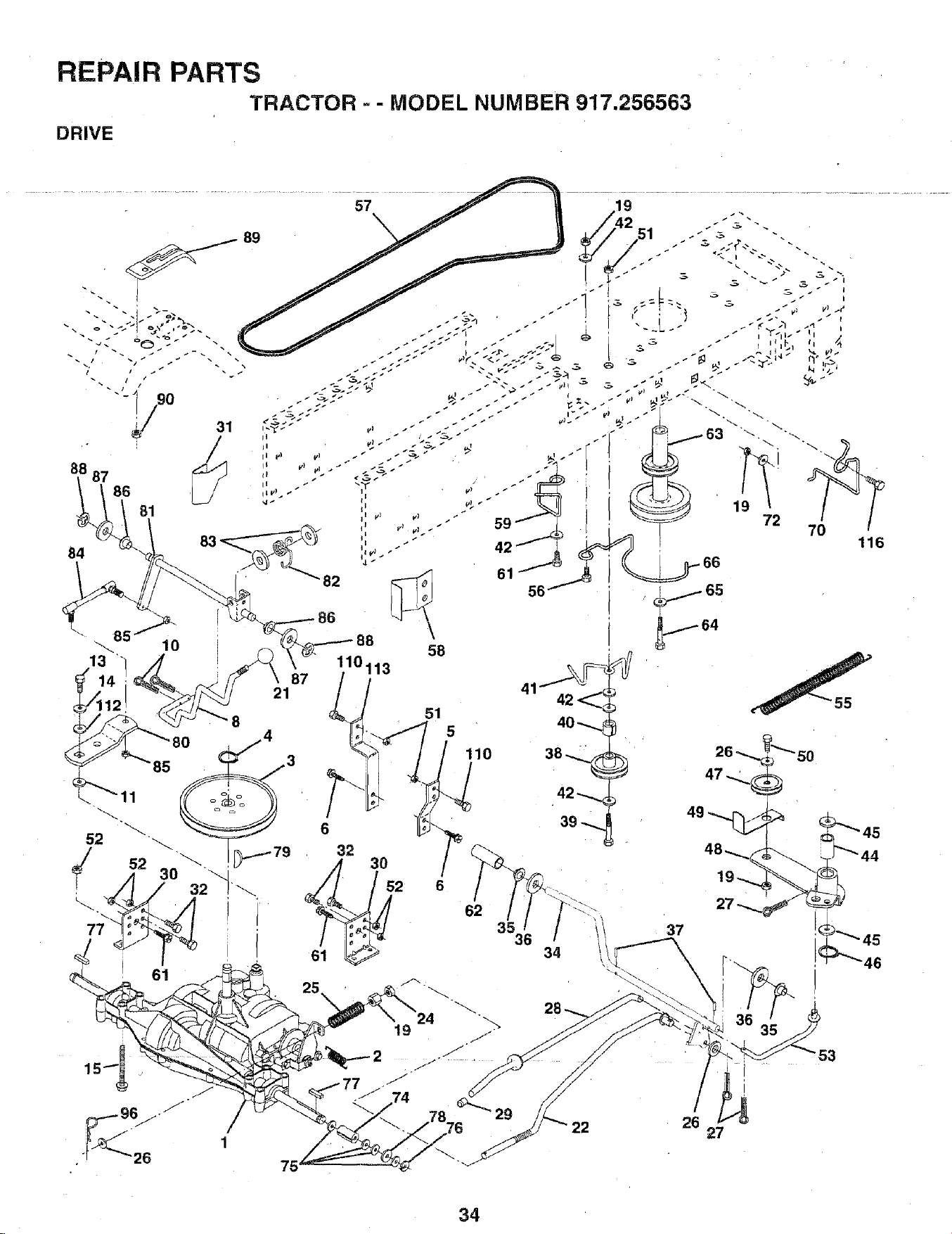
REPAIR PARTS
TRACTOR ° - MODEL NUMBER 917.256563
DRIVE
84
13
110113
87
21
75
51
5
110
6
62
34
37
26
53
I
27
34
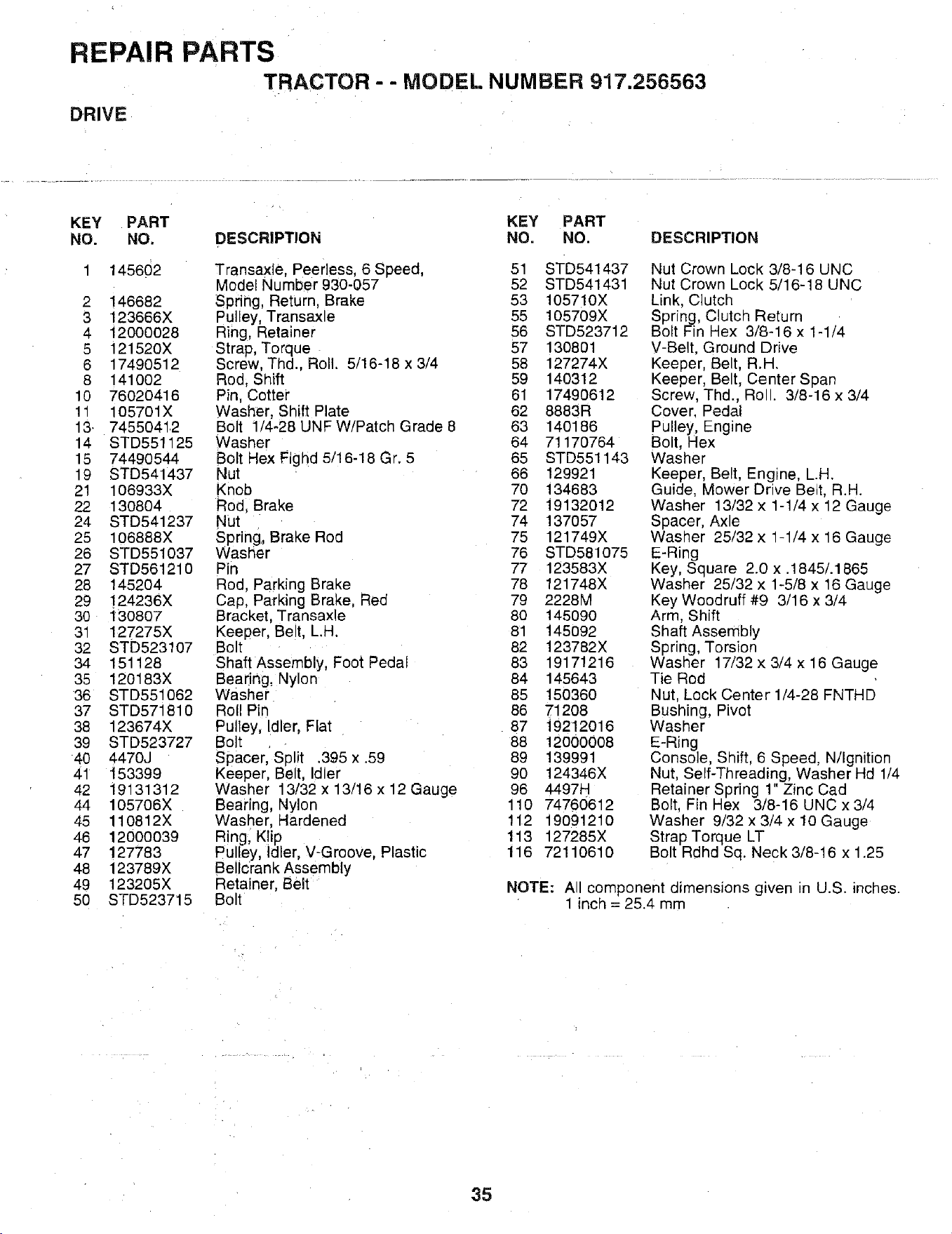
REPAIR
DRIVE
PARTS
TRACTOR - - MO DEL NUM BER 917.256563
KEY PART KEY PART
NO. NO. DESCRIPTION NO. NO. DESCRIPTION
1 145602 Transaxle, Peerless, 6 Speed,
Model Number 930-057
2 146682 Spring, Return, Brake
3 123666X Pulley, Transaxle
4 12000028 Ring, Retainer
5 121520X Strap, Torque
6 17490512 Screw, Thd., Roll. 5/16-18 x 3/4
8 141002 Rod, Shift
10 76020416 Pin, Cotter
11 105701X Washer, Shift Plate
13. 74550412 Bolt 1/4-28UNFW/PatchGrade8
14 STD551125 Washer
15 74490544 Bolt Hex Flghd 5/16-18 Gr. 5
19 STD541437 Nut
21 106933X Knob
22 130804 Rod, Brake
24 STD541237 Nut
25 106888X Spring, Brake Rod
26 STD551037 Washer
27 STD561210 Pin
28 145204 Rod, Parking Brake
29 !24236X Cap, Parking Brake, Red
30 130807 Bracket, Transaxle
31 127275X Keeper, Belt, L.H.
32 STD523107 Bolt
34 151128 Shaft Assembly, Foot Pedal
35 120183X Bearing, Nylon
36 STD551062 Washer
37 STD571810 Roll Pin
38 123674X Pulley, Idler, Flat
39 STD523727 Bolt
40 4470J Spacer, Split .395 x .59
4" 153399 Keeper, Belt, Idler
42 19131312 Washer 13/32 x 13/16 x 12 Gauge
44 105706X Bearing, Nylon
45 110812X Washer, Hardened
46 12000039 Ring, Kip
47 127783 PulleY, Idler, V-Groove, Plastic
48 123789X Bellc'rankAssembly
49 123205X Retainer, Belt
50 STD523715 Bolt
51 STD541437
52 STD541431
53 105710X
55 105709X
56 STD523712
57 130801
58 127274X
59 140312
61 1749O612
62 8883R
63 140186
64 71170764
65 STD551143
66 129921
70 134683
72 19132012
74 137057
75 121749X
76 STD581075
77 123583X
78 121748X
79 2228M
80 145090
81 145O92
82 123782X
83 19171216
84 145643
85 150360
86 71208
87 i9212016
88 12000008
89 139991
90 124346X
96 4497H
110 74760612
112 19091210
113 127285X
116 72110610
Nut Crown Lock 3/8-16 UNC
Nut Crown Lock 5/16-18 UNC
Link, Clutch
Spring, Clutch Return
Bolt Fin Hex 3/8-16 x 1-1/4
V-Belt, Ground Drive
Keeper, Belt, R.H.
Keeper, Belt, Center Span
Screw, Thd., Roll. 3/8-16 x 3/4
Cover, Pedal
Pulley, Engine
Bolt, Hex
Washer
Keeper, Belt, Engine, L.H.
Guide, Mower Drive Belt, R.H.
Washer 13/32 x 1-1/4 x 12 Gauge
Spacer, Axle
Washer 25/32 x 1-1/4 x 16 Gauge
E-Ring
Key, Square 2.0 x .1845/.1865
Washer 25/32 x 1-5/8 x 16 Gauge
Key Woodruff #9 3/16 x 3/4
Arm, Shift
Shaft Assembly
Spring, Torsion
Washer 17/32 x 3/4 x 16 Gauge
Tie Rod
Nut, Lock Center 1/4-28 FNTHD
Bushing, Pivot
Washer
E-Ring
Console, Shift, 6 Speed, N/Ignition
Nut, Self-Threading, Washer Hd 1/4
Retainer Spring 1" Zinc Cad
Bolt, Fin Hex 3/8-16 UNC x 3/4
Washer 9/32 x 3/4 x 10 Gauge
Strap Torque LT
Bolt Rdhd Sq. Neck 3/8-16 x 1.25
NOTE: All component dimensions given in U.S. inches.
1 inch = 25.4 mm
35
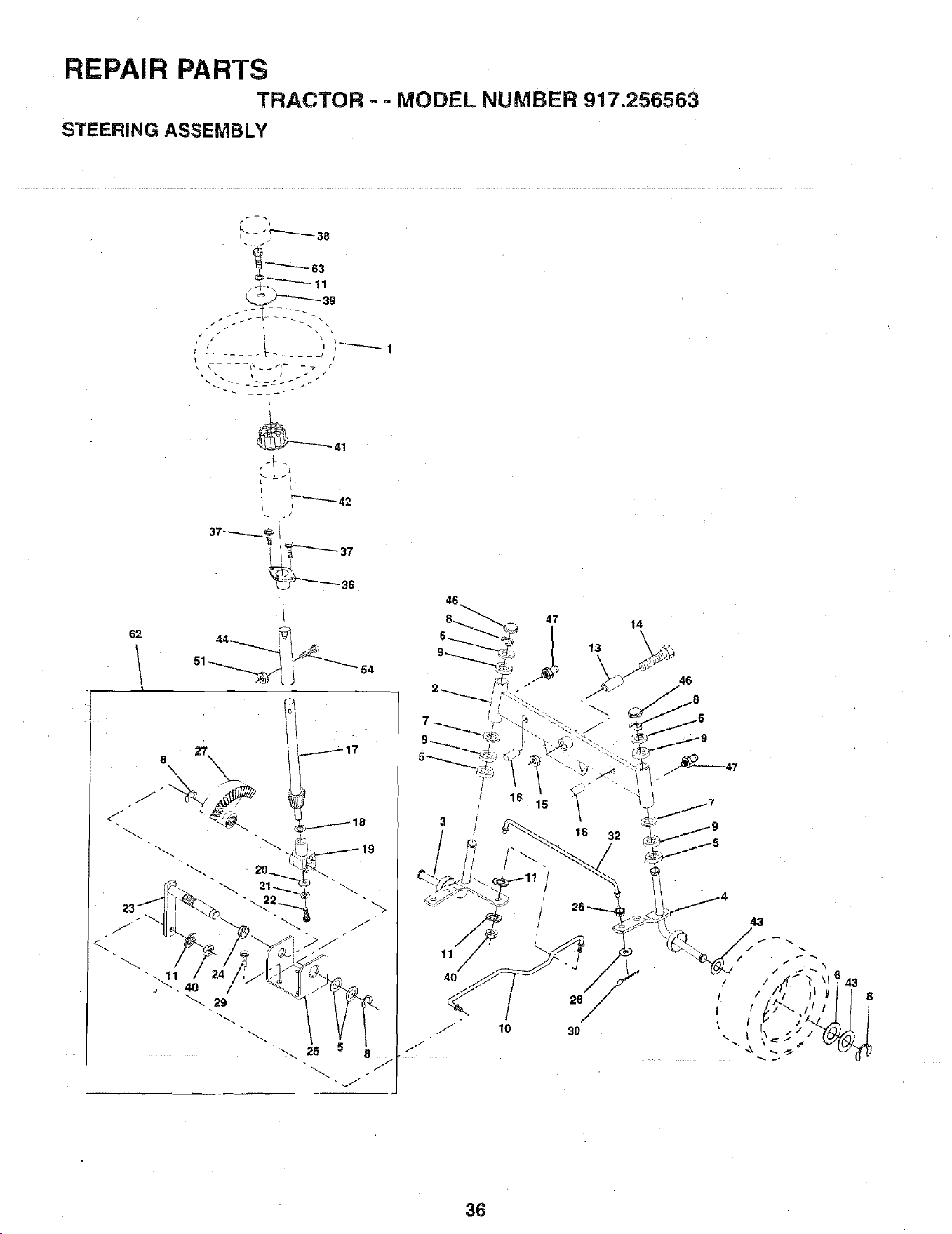
REPAIR PARTS
TRACTOR - - MODEL NUMBER 917.256563
STEERING ASSEMBLY
62
_-_"_--'-"'-_ 11
39
c"
L
44 _ _
8 27\
j17
. 40
29
25
3
11
40
14
s..17
il -
28
3O
36
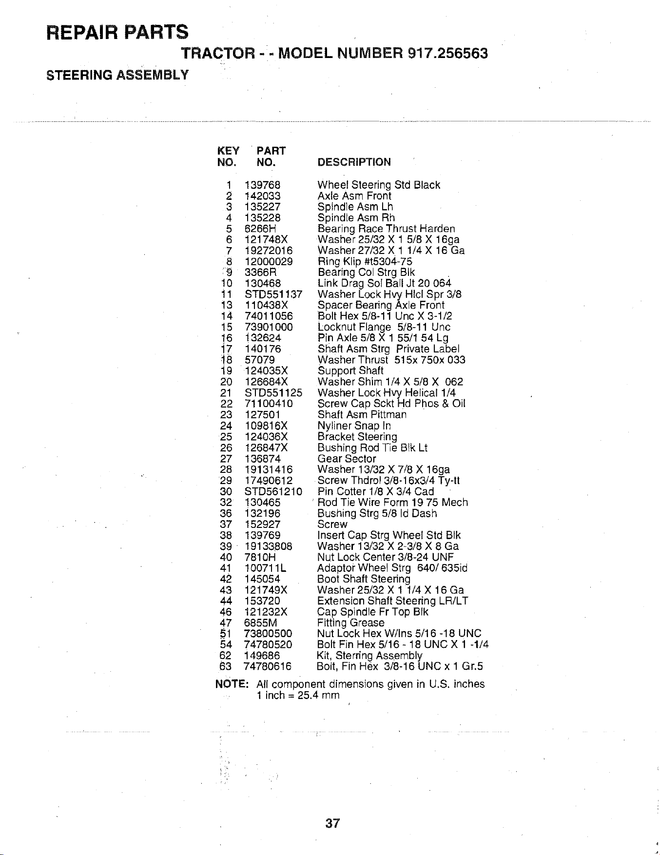
REPAIR PARTS
TRACTOR - - MODEL NUMBER 917.256563
STEERING ASSEMBLY
KEY PART
NO, NO. DESCRIPTION
t 139768
2 142033
3 135227
4 135228
5 6266H
6 121748X
7 19272016
8 12000029
_9 3366R
10 130468
11 STD551137
13 110438X
14 74011056
15 73901000
16 132624
17 140176
_8 57079
19 124035X
20 126684X
21 STD551125
22 71100410
23 127501
24 109816X
25 124036X
26 126847X
27 136874
28 19131416
29 17490612
30 STD561210
32 130465
36 132196
37 152927
38 139769
39 19133808
40 7810H
41 100711L
42 145054
43 121749X
44 153720
46 121232X
47 6855M
_1 73800500
54 74780520
62 149686
63 74780616
Wheel Steering Std Black
Axle Asm Front
Spindle Asm Lh
Spindle Asm Rh
Bearing Race Thrust Harden
Washer 25/32 X 1 5/8 X 16ga
Washer 27/32 X 1 1/4 X 16 Ga
Ring Klip #t5304-75
Bearing Col Strg BIk
Link Drag Sol Ball Jt 20 064
Washer Lock Hvy HIcl Spr 3/8
Spacer Bearing Axle Front
Bolt Hex 5/8-11 Unc X 3-1/2
Locknut Flange 5/8-11 Unc
Pin Axle 5/8 X 1 55/1 54 Lg
Shaft Asm Strg Private Label
Washer Thrust 515x 750x 033
Support Shaft
Washer Shim 1/4 X 5/8 X 062
Washer Lock Hvy Helical 1/4
Screw Cap Sckt Hd Phos & Oil
Shaft Asm Pittman
Nyliner Snap In
Bracket Steering
Bushing Rod Tie Blk Lt
Gear Sector
Washer 13/32 X 7/8 X 16ga
Screw Thdrol 3/8-16x3/4 Ty-tt
Pin Cotter 1/8 X 3/4 Cad
' Rod Tie Wire Form 19 75 Mech
Bushing Strg 5/8 Id Dash
Screw
Insert Cap Strg Wheel Std BIk
Washer 13/32 X 2-3/8 X 8 Ga
Nut Lock Center 3/8-24 UNF
Adaptor Wheel Strg 640/635id
Boot Shaft Steering
Washer 25/32 X 1 1/4 X 16 Ga
Extension Shaft Steering LR/LT
Cap Spindle Fr Top BIk
Fitting Grease
Nut Lock Hex W/Ins 5/16 -18 UNC
Bolt Fin Hex 5/16 - 18 UNC X 1 -1/4
Kit, Sterring Assembly
Bolt, Fin Hex 3/8-16 UNC x 1 Gr.5
NOTE: All component dimensions given in U.S. inches
1 inch = 25.4 mm
?
37
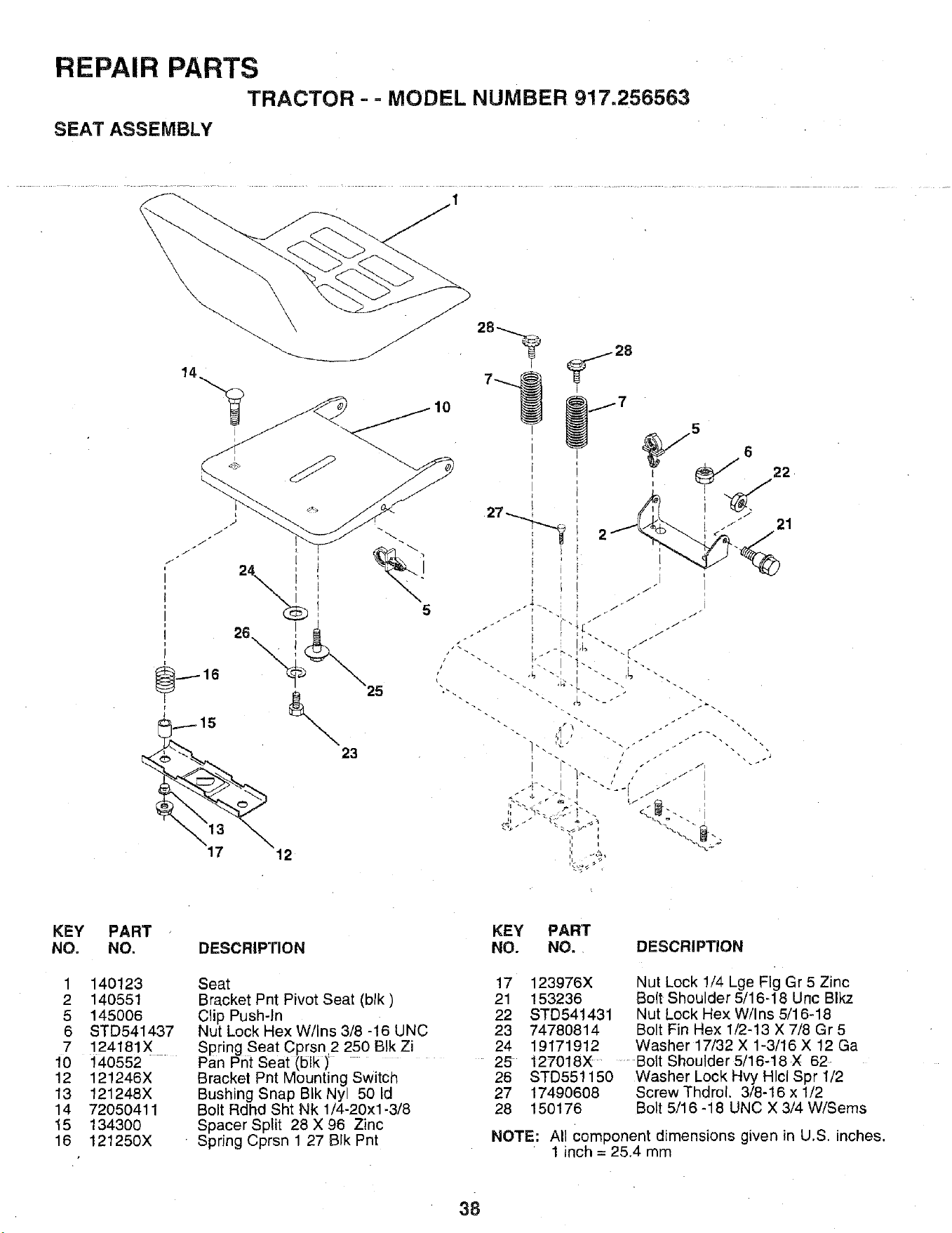
REPAIR PARTS
TRACTOR - - MODEL NUMBER 917.256563
SEAT ASSEMBLY
I
KEY
NO.
1
2
5
6
7
10
12
13
14
t5
16
PART
NO.
140123
140551
145006
STD541437
124181X
140552
121246X
121248X
72O50411
134300
121250X
KEY PART
DESCRIPTION NO. NO. DESCRIPTION
Seat
Bracket Pnt Pivot Seat (blk)
Clip Push-In
Nut Lock Hex W/Ins 3/8 -16 UNC
Spring Seat Cprsn 2 250 BIk Zi
Pan Pnt Seat (blk)
Bracket Pnt Mounting Switch
Bushing Snap B!k Nyl 50 Id
Bolt Rdhd Sht Nk 1/4-20xl-3/8
Spacer Split 28 X 96 Zinc
Spring Cprsn 1 27 BIk Pnt
NOTE:
17 123976X Nut Lock 1/4 Lge Fig Gr 5 Zinc
21 153236 Bolt Shoulder 5/16-18 Unc Blkz
22 STD541431 Nut Lock Hex W/Ins 5/16-18
23 74780814 Bolt Fin Hex 1/2-13 X 7/8 Gr 5
24 19171912 Washer 17/32 X 1-3/16 X 12 Ga
25 127018X Bolt Shoulder 5/16-t8 X 62
26 STD551150 Washer Lock Hvy Hlcl Spr 1/2
27 17490608 Screw Thdrol. 3/8-16 x 1/2
28 150176 Bolt 5/16-18 UNC X 3/4 W/Seres
All Component dimensions given in U.S. inches.
1 inch = 25.4 mm
38
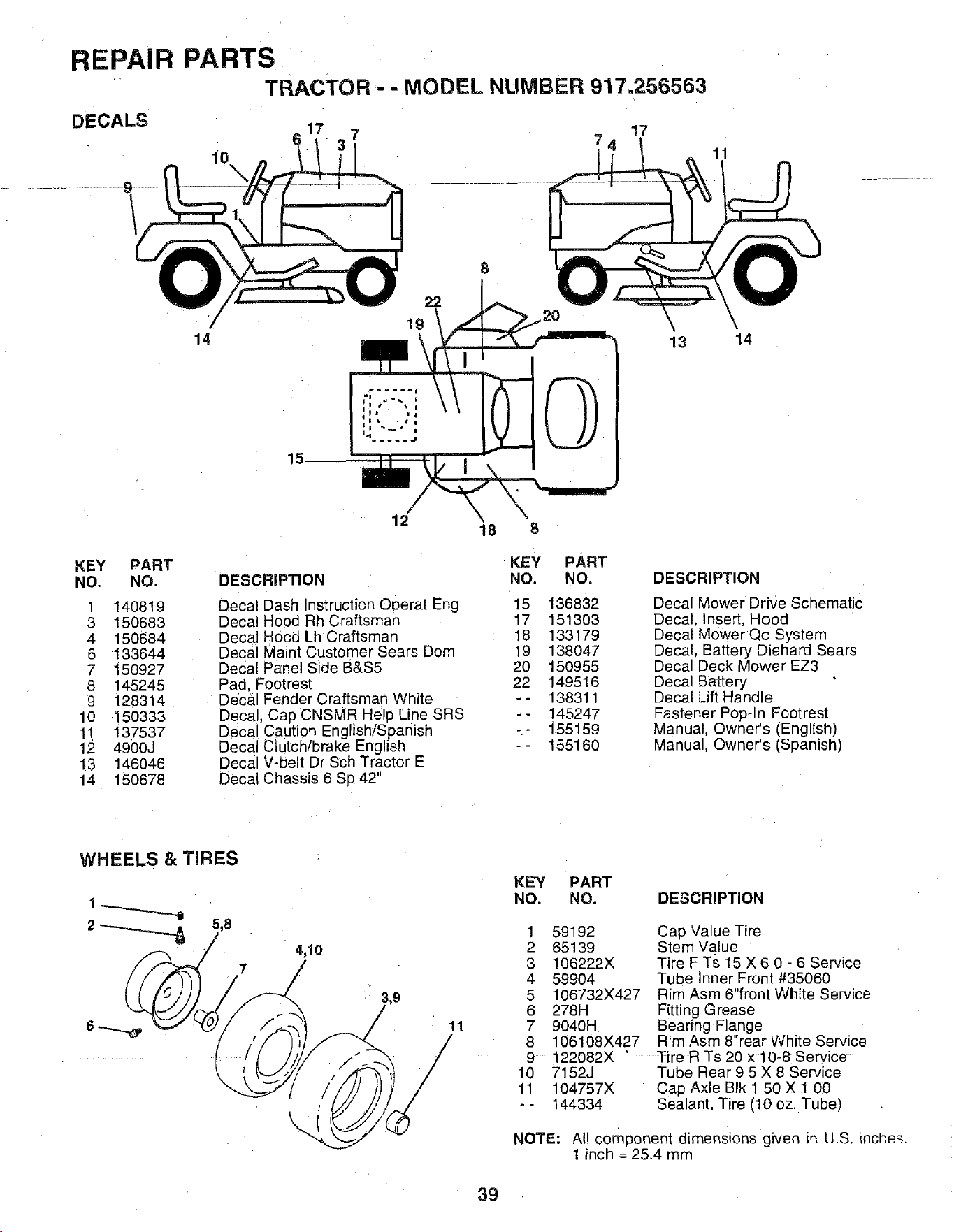
REPAIR PARTS
' TRACTOR =- MODEL NUMBER 917.256563
DECALS
10
\
6 1 7 7 17
11
7 19 \, \
14 13 14
15
12
"18
KEY PART KEY PART
NO. NO. DESCRIPTION NO. NO. DESCRIPTION
Decal Dash Instruction Ooeral Eng 15 136832
Decal Hood Rh Craftsman 17 151303
Decal Hood Lh Craftsman 18 133179
Decal Maint Customer Sears Dom 19 138047
Decal Panel Side B&S5 20 150955
Pad. Footrest 22 149516
Deca Fender Craftsman White -- 138311
Decal, Cap CNSMR Held Line SRS -- 145247
Deca Caution English/Spanish -- "155159
Decal Clutch/brake English - - 155160
Decal V-belt Dr Sch Tractor E
Decal Chassis 6 Sp 42"
1 140819
3 150683
4 15O684
6 133644
7 150927
8 145245
9 128314
10 150333
11 137537
12 4900J
13 146046
14 150678
Decal Mower Drive Schematic
Decal. Insert, Hood
Decal Mower Qc System
Decal. Battery Diehard Sears
Decal Deck Mower EZ3
Deca Battery
Decal Lift Handle
Fastener Pop-In Footrest
Manual. Owner's (English)
Manual, Owner's (Spanish)
WHEELS & TIRES
4,10
7
KEY PART
NO. NO.
DESCRIPTION
11
1
2
3
4
5
6
7
8
59192
65139
106222X
59904
106732X427
278H
9040H
106108X427
Cap Value Tire
Stem Value
Tire F Ts 15 X 6 0 - 6 Service
Tube Inner Front #35060
Rim Asm 6"front White Service
Fitting Grease
Bearing Flange
Rim Asm 8"rear White Service
9 122082X " Tire R Ts 20 x 10-8 Service
10 7152J Tube Rear 9 5 X 8 Service
11 104757X Cap Axle BIk 1 50 X 1 00
- - 144334 Sealant, Tire (10 oz. Tube)
NOTE: Air component dimensions given in U.S. inches,
1 inch = 25.4 mm
39
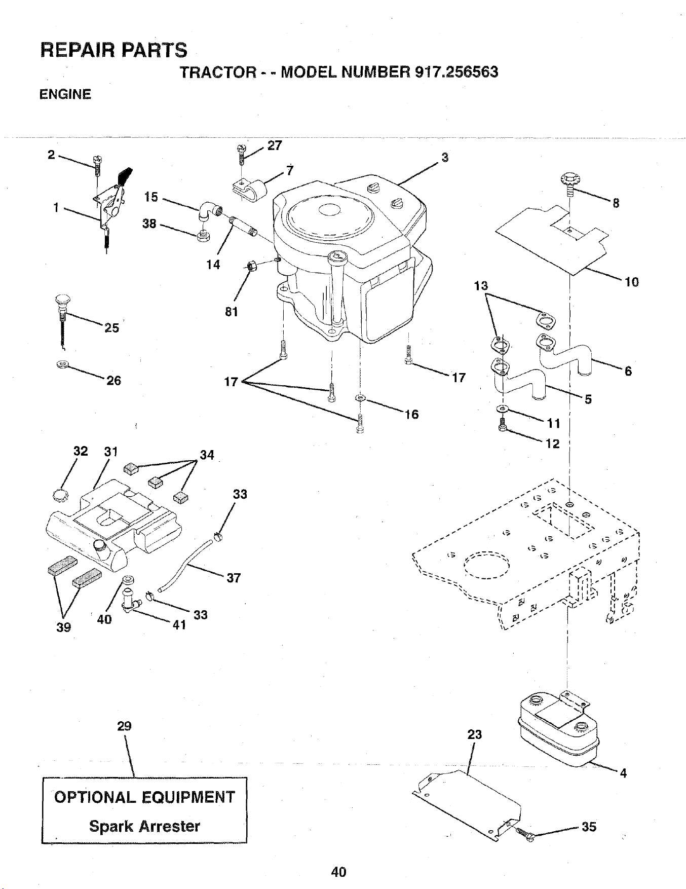
REPAIR PARTS
TRACTOR - - MODEL NUMBER 917.256563
ENGINE
27
3
14
81
25
32 31
40
39
34
I
6
I
12
33
/
37
29
\
OPTIONAL EQUIPMENT
• Spark Attester
4O
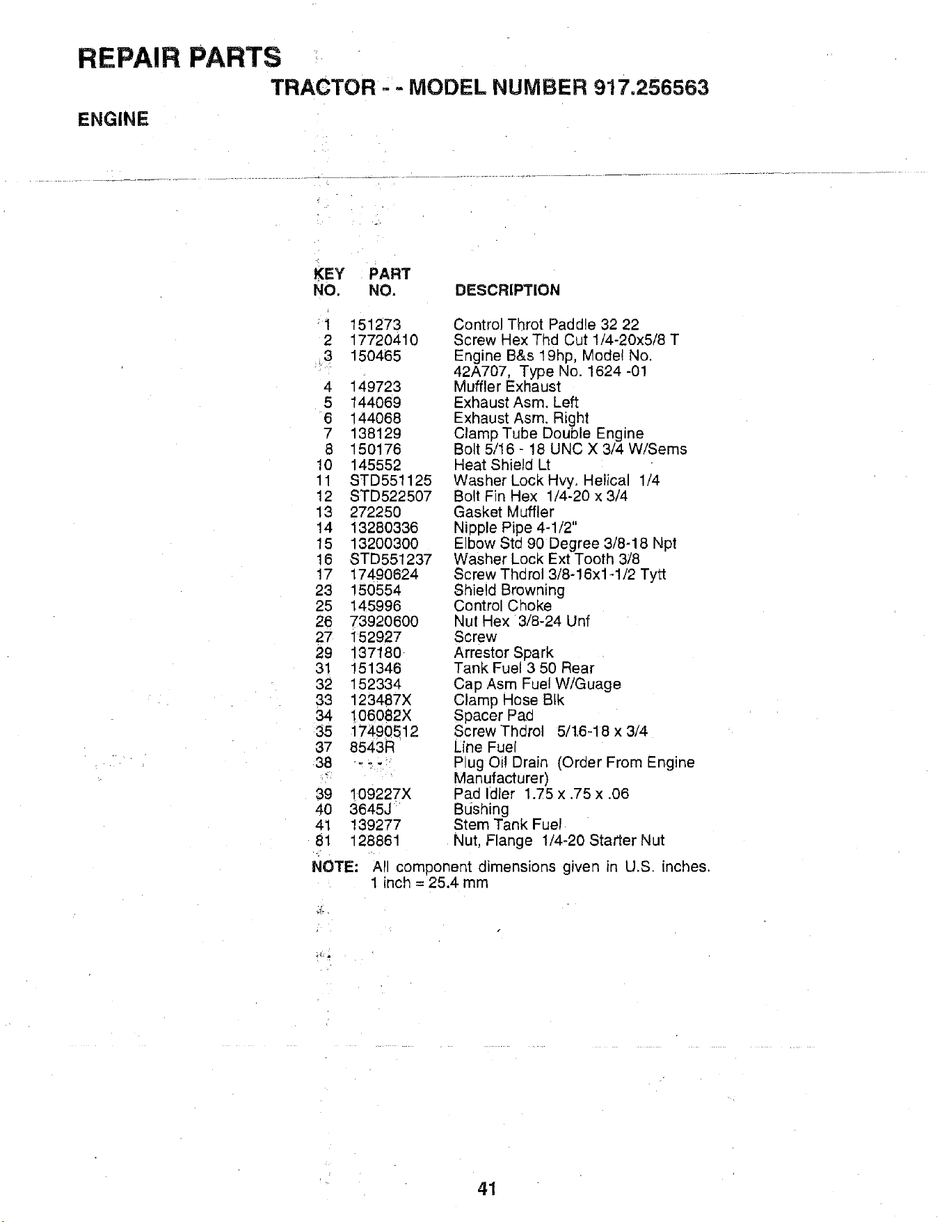
REPAIR PARTS
TRACTOR = - MODEL NUMBER 917.256563
ENGINE
KEY PART
NO. NO. DESCRIPTION
1 151273
2 17720410
3 150465
4 149723
5 144069
6 144068
7 138129
8 150176
10 145552
11 STD551125
12 STD522507
13 272250
14 13280336
15 13200300
16 STD551237
17 17490624
23 150554
25 145996
26 7392O6O0
27 152927
29 137180
31 151346
32 152334
33 123487X
34 106082X
35 17490512
37 8543R
38 ---
39 109227X
4O 3645J
41 139277
81 128861
Control Throt Paddle 32 22
Screw Hex Thd Cut 1/4-20x5/8 T
Engine B&s 19hp, Mode! No.
42A707, Type No. 1624 -01
Muffler Exhaust
Exhaust Asm. Left
Exhaust Asm. Right
Clamp Tube Double Engine
Bolt 5/16 - 18 UNC X 3/4 W/Sems
Heat Shield Lt
Washer Lock Hvy. Helical 1/4
Bolt Fin Hex 1/4-20 x 3/4
Gasket Muffler
Niople Pipe 4-1/2"
Elbow Std 90 Degree 3/8-18 Npt
Washer Lock Ext Tooth 3/8
Screw Thdml 3/8-16x1-1/2 Tytt
Shield Browning
Control Choke
Nul Hex 3/8-24 Unf
Screw
Arrestor Spark
Tank Fuel 3 50 Rear
Cap Asm Fuel W/Guage
Clamp Hose BIk
Spacer Pad
Screw Thdrol 5/1.6-18 x 3/4
Line Fuel
Plug Oi! Drain (Order From Engine
Manufacturer)
Pad Idler 1.75 x .75 x .06
Bushing
Stem Tank Fuel
Nut, Flange 1/4-20 Starter Nut
NOTE: All component dimensions given in U.S. inches.
1 inch = 25.4 mm
41
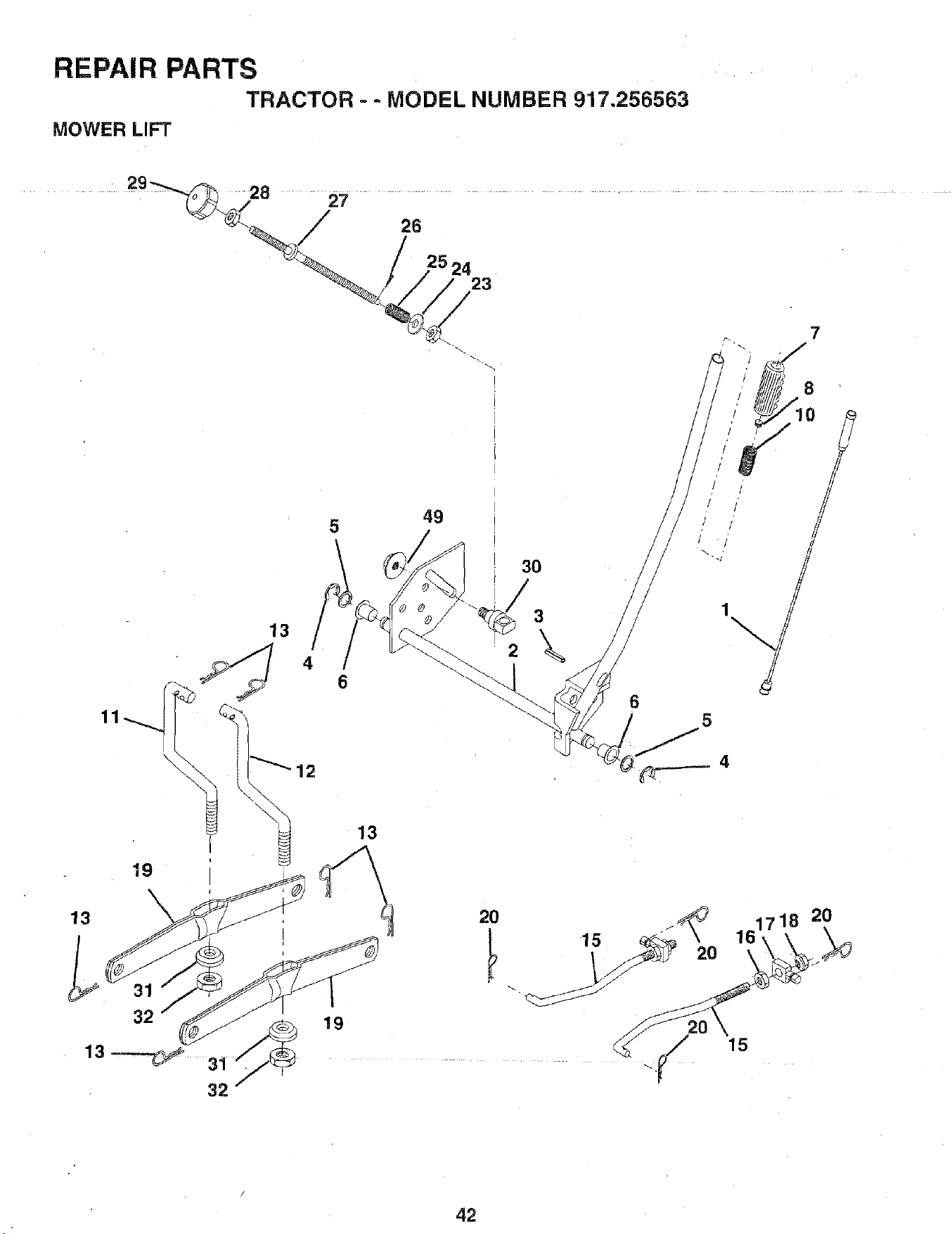
REPAIR PARTS
TRACTOR - - MODEL NUMBER 917.256563
MOWER LIFT
- 28 " 27 ........
26
23
11
49
19
i 3O
13
\
6
7
8
5
13
32
32--
19
20 20
161,718 20
42
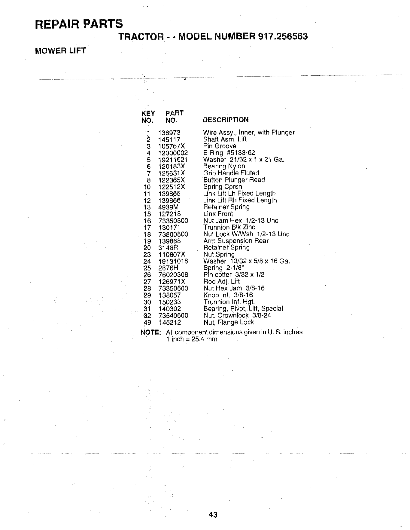
REPAIR PARTS
TRACTOR - - MODEL NUMBER 917.256563
MOWER LIFT
KEY PART
NO. NO. DESCRIPTION
1 136973
2 145117
3 105767X
4 12000002
5 19211621
6 120183X
7 125631X
8 122365X
10 122512X
11 139865
12 139866
13 4939M
15 127248
16 733508OO
17 130171
18 73800800
19 139868
20 3146R
23 110807X
24 19131016
25 2876H
26 7602O308
27 126971X
28 73350600
29 138057
3O 150233
31 14O302
32 73540600
49 14521.2
Wire Assy., Inner, with Plunger
Shaft Asm. Lift
Pin Groove
E Ring #5133-62
Washer 21/32 x 1 x 21 Ga.
Bearing Nyton
Grip Handle Fluted
Button Plunger Read
Spring Cprsn
Link Lift Lh Fixed Length
Link Lift Rh Fixed Length
Retainer Spring
Link Front
Nut Jam Hex 1/2-13 Unc
Trunnion BIk Zinc
Nut Lock WANsh 1/2-13 Unc
Arm Suspension Rear
Retainer Spring
Nut Spring
Washer 13/32 x 5/8 x 16 Ga.
Spring 2-1/8"
Pin cotter 3/32 x 1/2
Rod Adj. Lift
Nut Hex Jam 3/8-16
Knob nf. 3/8-16
Trunnion Inf. Htt.
Bearing, Pivot, ift,Special
Nut. Crownlock 3/8-24
Nut, Flange Lock
NOTE: All comDonentdimensions given n U. S. inches
1 incl_ = 25.4 mm
43
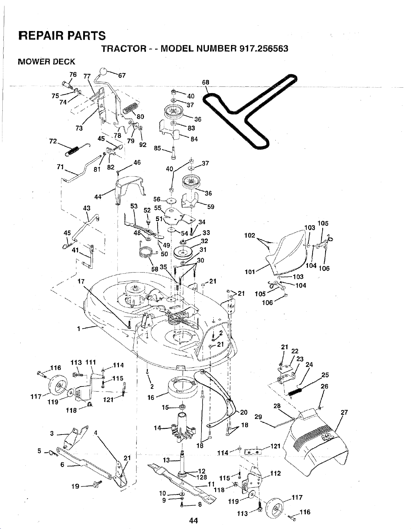
REPAIR PARTS
TRACTOR " - MODEL NUMBER 917.256563
MOWER DECK
73
52
58
34
33
32
25
26
27
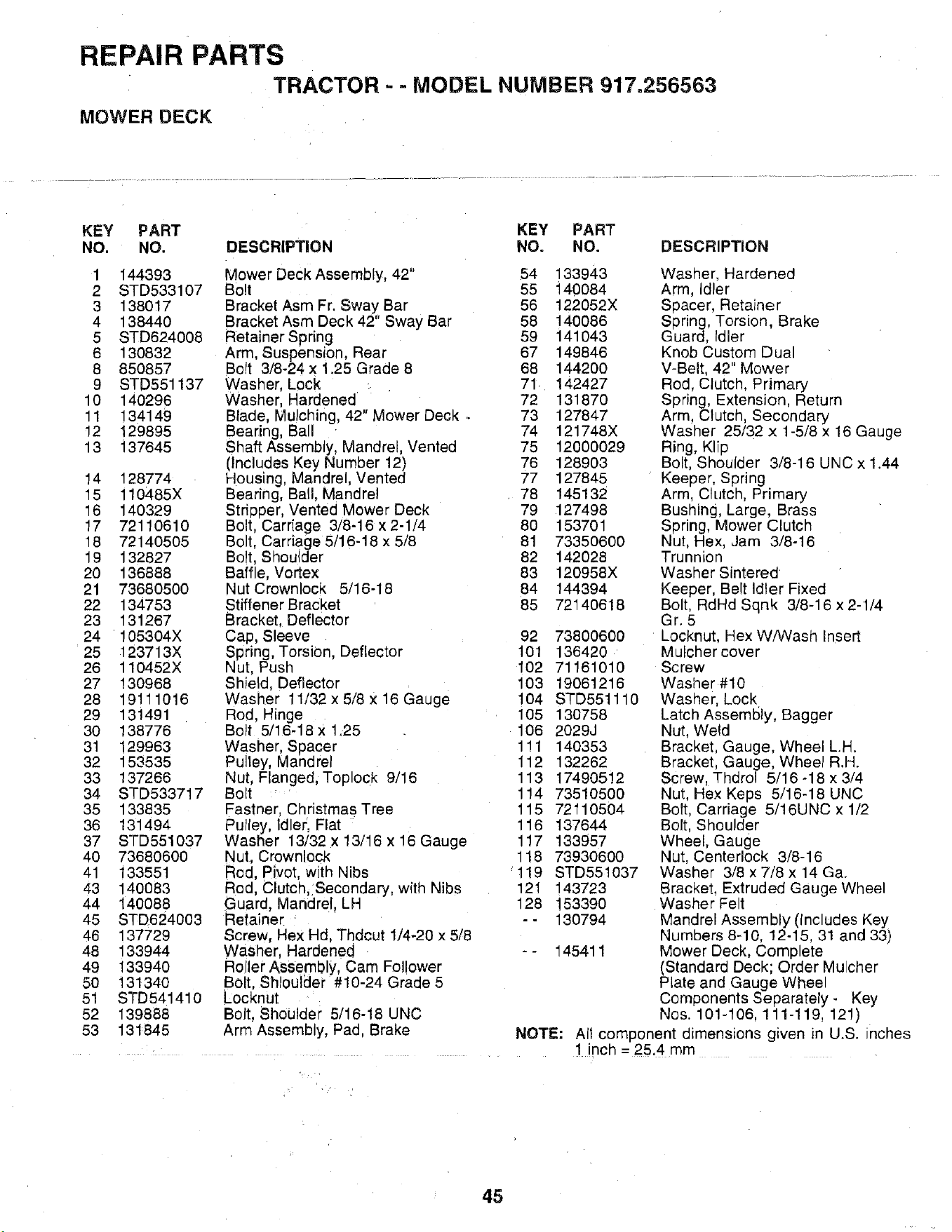
REPAIR PARTS
TRACTOR - - MODEL NUMBER 917.256563
MOWER DECK
KEY PART KEY PART
NO. NO. DESCRIPTION NO. NO. DESCRIPTION
1 144393
2 STD533107
3 138017
4 138440
5 STD624008
6 130832
8 850857
9 STD551137
10 140296
11 134149
!2 129895
13 137645
14 128774
15 110485X
16 140329
17 72110610
18 72140505
19 132827
20 136888
21 73680500
22 134753
23 131267
24 105304X
25 123713X
26 110452X
27 130968
28 19111016
29 131491
30 138776
31 129963
32 153535
33 137266
34 STD533717
35 133835
36 131494
37 STD551037
4O 736806OO
41 133551
43 140083
44 140088
45 STD624003
46 137729
48 133944
49 133940
5O 13134O
51 STD541410
52 139888
53 131845
Mower Deck Assembly, 42" 54 133943
Bolt 55 _140084
Bracket Asm Fr. Sway Bar 56 122052X
Bracket Asm Deck 42" Sway Bar 58 140086
Retainer Spring 59 141043
Arm, Suspension, Rear 67 149846
Bolt 3/8-24 x 1.25 Grade 8 68 144200
Washer, Lock . 71 142427
Washer, Hardened 72 131870
Blade, Mulching, 42" Mower Deck _ 73 127847
Bearing, Ball 74 121748X
Shaft Assembly, Mandrel, Vented 75 12000029
(Includes Key Number 12) 76 128903
Housing, Mandrel, Vented 77 127845
Bearing, Ball, Mandrel 78 145132
Striooer, Vented Mower Deck 79 127498
Bolt Carriage 3/8-16 x 2-1/4 80 153701
Bolt, Carriage 5/16-18 x 5/8 81 73350600
Bolt. Shoulder 82 142028
Baffle, Vortex 83 120958X
Nut Crownlock 5/16-18 84 144394
Stiffener Bracket 85 72140618
Bracket. Deflector
Cap, Sleeve 92
Spring, TorsiOn, Deflector 101
Nut, Push 102
Shield. Deflector 103
Washer 11/32 x 5/8 x 16 Gauge 104
Rod, Hinge 105
Bolt 5/16-18 x 1.25 106
Washer, Spacer 111
Pulley, Mandrel 112
Nut, Flanged, Toplock 9/16 113
Bolt 114
Fastner, Christmas Tree 115
Pulley, Idler, Flat 116
Washer 13/32 x 13/16 x 16 Gauge 117
Nut, Crownlock 118
Rod, Pivot, with Nibs 119
Rod, Clutch, Secondary, with Nibs 121
Guard, Mandrel, LP 128
Retainer - -
Screw, Hex Hd Thdcut 1/4-20 x 5/8
Washer, Hardened - - 145411
Rojler Assembly, Cam Foil ower
Bolt, Shlouider #10-24 Grade 5
Locknut
Bolt, Shoulder 5/16-18 UNC
Arm Assembly, Pad Brake NOTE:
73800600
136420
71161010
19061216
STD551110
130758
2029J
140353
132262
17490512
73510500
72110504
137644
133957
73930600
STD551037
143723
153390
130794
Washer, Hardened
Arm, Idler
Spacer, Retainer
Spring, Torsion, Brake
Guard, Idler
Knob Custom Dual
V-Belt, 42" Mower
Rod, Clutch, Primary
Spring, Extension, Return
Arm, Clutch, Secondary
Washer 25/32 x 1-5/8 x 16 Gauge
Ring, Klip
Bolt, Shoulder 3/8-16 UNC x 1.44
Keeper, Spring
Arm, Clutch, Primary
Bushing, Large, Brass
Spring, Mower Clutch
Nut, Hex, Jam 3/8-16
Trunnion
Washer Sintered
Keeper, Belt Idler Fixed
Bolt, RdHd Sqnk 3/8-16 x 2-1/4
Gr. 5
Locknut, Hex W!Wash Insert
Mulcher cover
Screw
Washer #10
Washer, Lock
Latch Assembly, Bagger
Nut, Weld
Bracket, Gauge, Wheel L.H.
Bracket, Gauge, Wheel R.H.
Screw, Thdrol 5/16 -18 x 3/4
Nut, Hex Keps 5/16-18 UNC
Bolt, Carriage 5/16UNC x 1/2
Bolt, Shoulder
Wheel, Gauge
Nut, Centerlock 3/8-16
Washer 3/8 x 7/8 x 14 Ga.
Bracket, Extruded Gauge Wheel
Washer Felt
Mandrel Assembly (Includes Key
Numbers 8-10, 12-15, 31 and 33)
Mower Deck, Complete
(Standard Deck; Order Mu chef
Plate and Gauge Wheel
Components Separately- Key
Nos. 101-106, 111-119, 121)
All component dimensions given in U.S. inches
1 inch = 25.4 mm
45
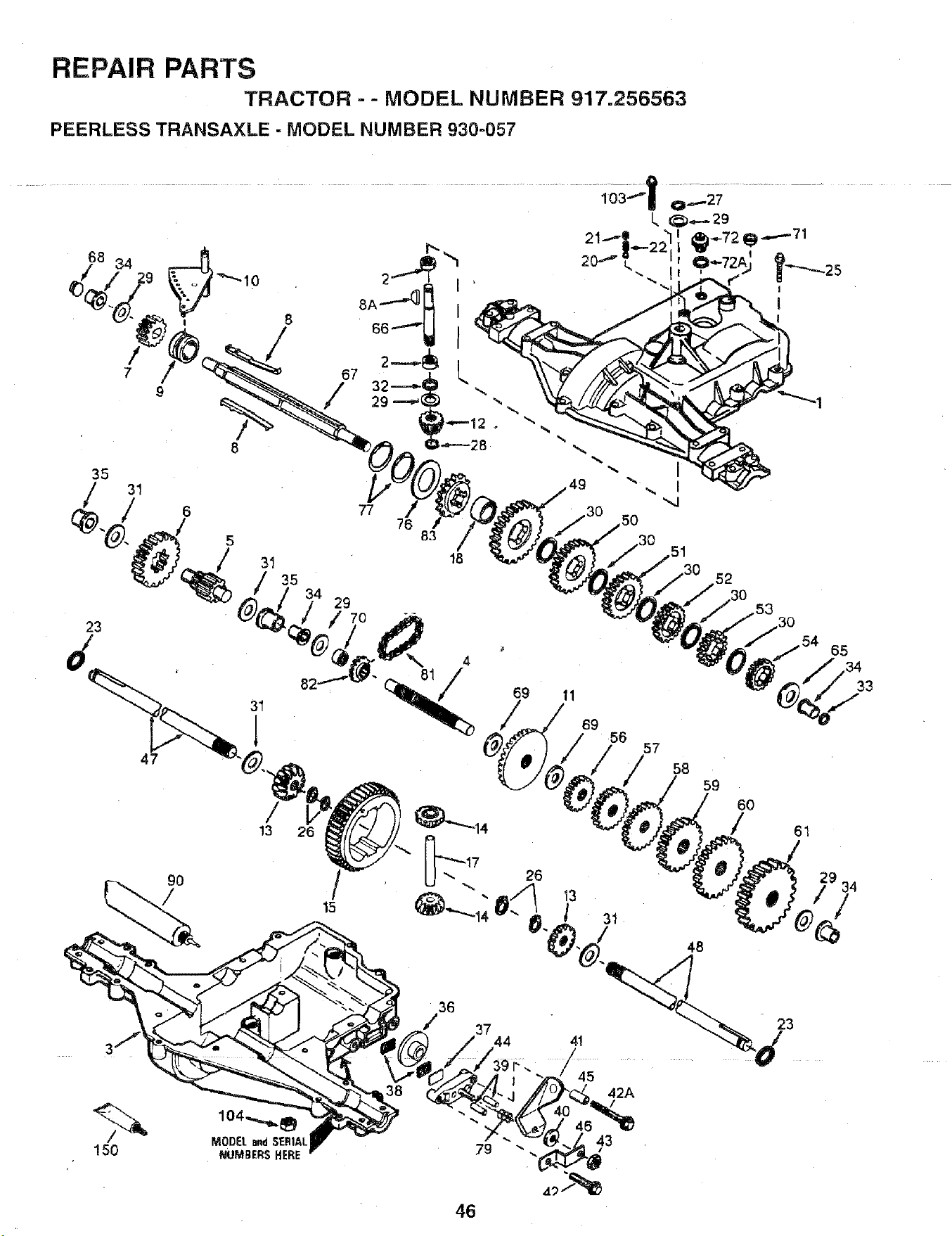
REPAIR PARTS
TRACTOR - - MODEL NUMBER 917.256563
PEERLESS TRANSAXLE - MODEL NUMBER 930-057
................................. +++-+|0:.-+_'.........
L, _+.- 29
68 34
8
/ /
7 67
° /
35
150
47
31
18
35 ,52
29 3O
70 ,53
/
13
15
\ 4
69 11
69
56
46
26
4!
45
43
65
57
59
6O
, 34
/
31 _
48
42A
33
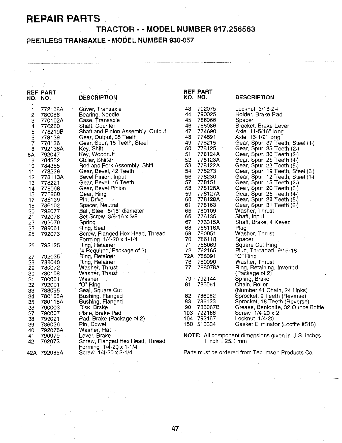
REPAIR PARTS
TRACTOR = = MODEL NUMBER 917.256563
PEERLESS TRANSAXLE MODEL NUMBER 930.057
REF PART REF PART
NO. NO. DESCRIPTION NO. NO. DESCRIPTION
1 772108A Cover, Transaxle 43 792075
2 780086 Bearing, Needle 44 790025
3 770102A Case Transaxle 45 786066
4 776260 Shaft. Counter 46 786086
5 776219B Shaft and Pinion Assembly, Output 47 774690
6 778139 Gear. Output 35 Teeth 48 774691
7 778136 Gear. Spur, 15 Teeth, Steel 49 778215
8 792136A Key, Shift 50 778125
8A 792047 Key, Woodruff 51 778124A
9 784352 Collar, Shifter 52 778123A
10 784355 Rod ana Fork Assembly, Shift 53 778122A
11 778229 Gear. Bevel 42 Teeth 54 778273
12 778113A Bevel Pinion: Input 56 778230
13 778221 Gear. Bevel, 16 Teeth 57 778151
14 778068 Gear, Bevel Pinior 58 778126A
15 778260 Gear, Ring 59 778127A
17 786139 Pin, Drive 60 778128A
18 786102 Spacer, Neutral 61 778163
20 792077 Ba , Stee 5/16" diameter 65 780109
21 792078 Set Screw 3/8:16 x 3/8 66 776135
22 792079 Spring 67 776315A
23 788061 Ring, Seal 68 786116A
25 792073 Screw. Flanged Hex Head, Thread 69 780051
Forming 1/4-20x 1-1/4 70 786118
26 792125 Ring Retainer 71 788069
(4 Requ red; Package of 2) 72 792165
27 792035 Ring, Retainer 72A 788091
28 788040 Ring, Retainer 76 780090
29 780072 Washer, Thrust 77 788078A
30 780108 Washer, Thrust
31 780001 Washer 79 792144
32 792001 "O" Ring 81 786081
33 788095 Seat, Sauare Cut
34 780105A Bushing, Flanged 82 786082
35 780118A Bushing, Flanged 83 786123
36 790003 Disk. Brake 90 788067B
37 790007 Plate, Brake Pad 103 792166
38 799021 Pad. Brake (Package of 2) 104 792167
39 786026 Pit, Dowel 150 510334
40 792076A Washer, Fiat
41 790079 Lever, Brake
42 792073 Screw, Flanged Hex Head, Thread
Forming 1/4_20x 1-1/4
42A 792085A Screw 1/4-20 x2-1/4
_OCKnUt 5/16-24
Holder, Brake Pad
Spacer
Bracket Brake Lever
Axle 11-5/16" ong
Axle 16-1/2" long
Gear, Spur. 37 Teeth. Steel (1.)
Gear. Spur, 35 Teeth (2.)
Gear, Spur, 30 Teeth (3°)
Gear, Spur. 25 Teeth (4-)
Gear Spur. 22 Teeth (5.)
'Gear Spur, 19 Teeth, Steel (6.)
Gear Spur. 12 Teeth, Steel (!.)
Gear Spur. 15 Teeth (2..)
Gear Spur. 20 Teeth (3-)
Gear Spur. 25 Teeth (4-)
Gear Spur, 28 Teeth (5.)
Gear Sour. 31 Teeth (6.)
Washer Thrust
Shaft. Input
Shaft. Brake 4 Keyed
Plug
Washer Thrust
Spacer
Square Cut Ring
Plug, Threaded 9/16-18
"O" Ring
Washer. Thrust
Ring, Retaining, Inverted
(Package of 2)
Spring, Brake
Chain. Roller
(Number 41 Chain. 24 Links)
Sprocket. 9 Teeth (Reverse)
Sprocket. 18 Teeth (Reverse)
Grease. Bentonite, 32 Ounce Bottle
Screw 1/4-20 x 2
Locknut 1/4-20
Gasket Eliminator (Loctite #515)
NOTE: All component dimensions g_ven n U.S. inches
1 inch = 25.4 mm
Parts must be ordered from Tecumsen Products Co.
47
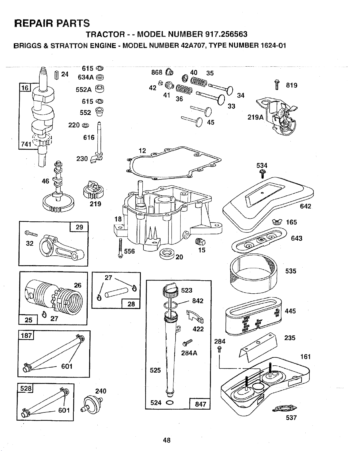
REPAIR PARTS
TRACTOR - - MODEL NUMBER 917.256563
BRIGGS & STRATTON ENGINE - MODEL NUMBER 42A707, TYPE NUMBER 1624-01
r_
24
634A _)
552A
615 q_
552
220 _
2ao
219
615
868 _ ,,_40 35
219A
534
642
, i
18
15
601
523I- 842
%
422
284A
525
524 (3) _
165
643
535
445
537
48
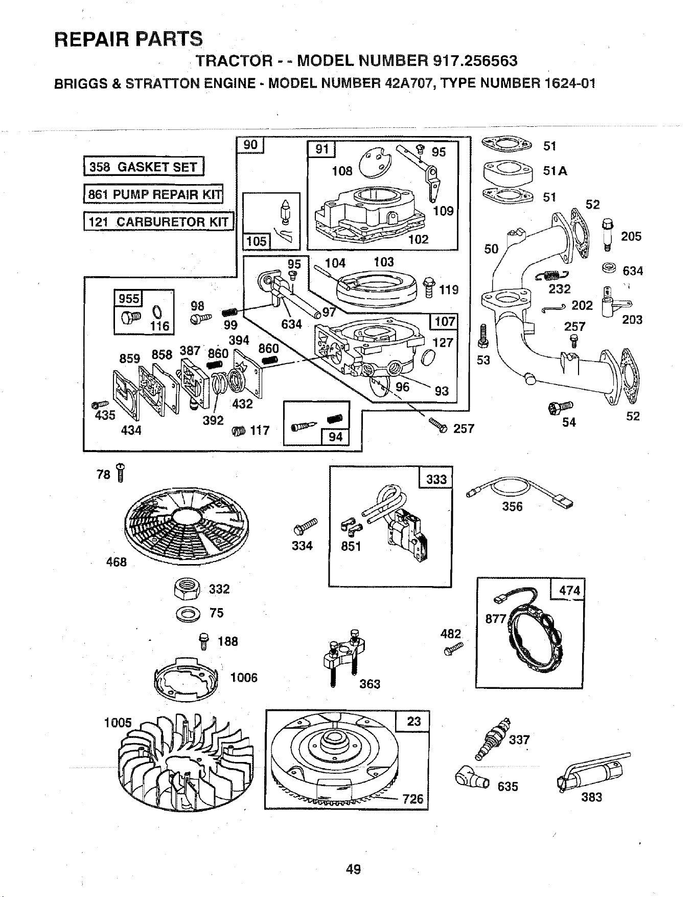
REPAIR PARTS
TRACTOR -= MODEL NUMBER 917.256563
BRIGGS & STRATTON ENGINE - MODEL NUMBER 42A707, TYPE NUMBER 1624-01
108
104 103
102
51
51A
52
232
202
257
54
205
634
52
78
468
_332
Q 7s
188
: 1006
334
_363
482
37
383
49
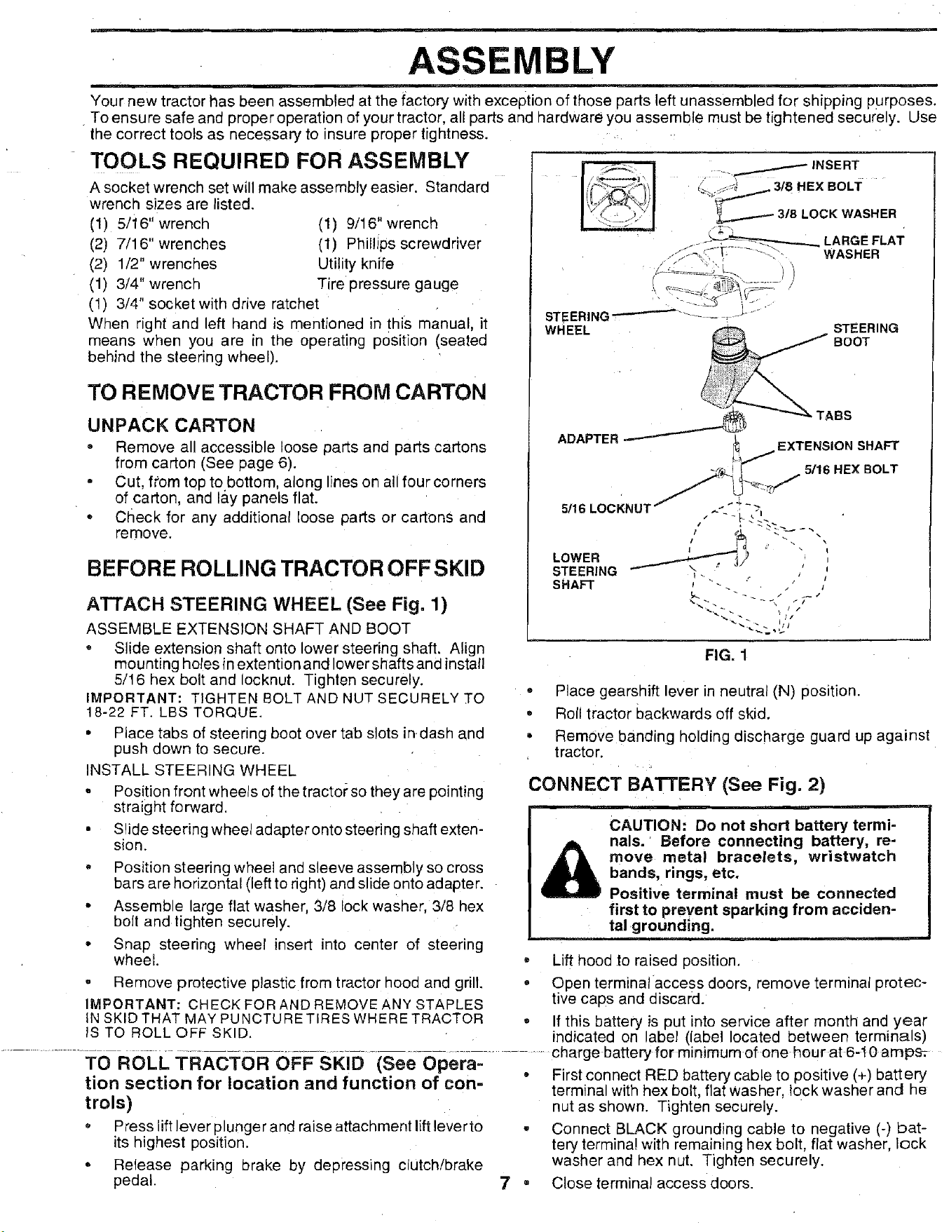
ASSEMBLY
Your new tractor has been assembled at the factory with exception of those parts left unassembled for shipping purposes,
To ensure safe and proper operation of your tractor, all parts and hardware you assemble must be tightened securely. Use
the correct tools as necessary to insure proper tightness.
TOOLS REQUIRED FOR ASSEMBLY
A socket wrench set will make assembly easier. Standard
wrench sizes are listed.
(1) 5/i6" wrench (1) 9/16" wrench
(2) 7/16" wrenches (1) Phillips screwdriver
(2) 1/2" wrenches Utility knife
(1) 3/4" wrench Tire pressure gauge
(1) 3/4" socket with drive ratchet
When right and left hand is mentioned in this manual, it
means when you are in the operating position (seated
behind the steering wheel).
TO REMOVE TRACTOR FROM CARTON
UNPACK CARTON
o Remove all accessible loose parts and parts cartons
from carton (See page 6).
• Cut, from top tobottom, along lines on all four corners
of carton, and lay panels flat.
• Check for any additional loose parts or cartons and
remove.
BEFORE ROLLING TRACTOR OFFSKID
ATTACH STEERING WHEEL (See Fig. 1)
ASSEMBLE EXTENSION SHAFT AND BOOT
° Slide extension shaft onto lower steering shaft. Align
mounting holes in extention and lower shafts and install
5/16 hex bolt and Iocknut. Tighten securely.
IMPORTANT: TIGHTEN BOLT AND NUT SECURELY TO
18-22 FT. LBS TORQUE.
• Place tabs of steering boot over tab slots in.dash and
push down to secure.
INSTALL STEERING WHEEL
° Position front wheels of the tractor so they are pointing
straight forward.
• Slide steering wheel adapter onto steering shaft exten-
sion.
, Position steering wheel and sleeve assembly so cross
bars are horizontal (left to right) and slide onto adapter.
• Assemble large flat washer, 3/8 iock washer, 3/8 hex
bolt and tighten securely.
* Snap steering wheel insert into center of steering
wheel.
• Remove protective plastic from tractor hood and grill,
IMPORTANT: CHECK FOR AND REMOVE ANY STAPLES
IN SKID THAT MAY PUNCTURE TIRES WHERE TRACTOR
IS TO ROLL OFF SKID.
• --...._.._.....-.-_ INSERT
;_.v_ 3/8 HEX BoLT
3/8 LOCK WASHER
_ LARGE LAT
..-iS"o ,_- [: ...... -._'- , WASHER
WHEEL
STEERING
BOOT
ADAPTER
• TABS
EXTENSION SHAFT
5/16 HEX BOLT
LOWER
STEERING
SHAFT
_'_ _ _ i_j /
FIG. 1
o Place gearshift lever in neutral (N) position.
• Roll tractor backwards off skid.
• Remove banding holding discharge guard up against
tractor.
CONNECT BATTERY (See Fig. 2)
CAUTION: Do not short battery termi-
nals. Before connecting battery, re-
move metal bracelets, wristwatch
bands, rings, etc.
Positive terminal must be connected
first to prevent sparking from acciden=
tal grounding.
• Lift hood .to raised position.
= Open terminal access doors, remove terminal protec-
tive caps and discard.
° If this battery is put into service after month and year
indicated on label (label located between terminals)
.............................................................................. charge battery for minimum of one hour at 6-t0 amps_
TO ROLL TRACTOR OFF SKID (See Opera- • First connect RED battery cable to positive (+) battery
tion section for location and function of con-
trois)
° Press lift lever plunger and raise attachment lift lever to
its highest position.
° Release parking brake by depressing clutch/brake
pedal.
terminal with hex bolt, flat washer, lock washer and he
nut as shown. Tighten securely.
° Connect BLACK grounding cable to negative (-) bat-
tery terminal with remaining hex bolt, flat washer, lock
washer and hex nut. Tighten securely.
7 • Close terminal access doors.
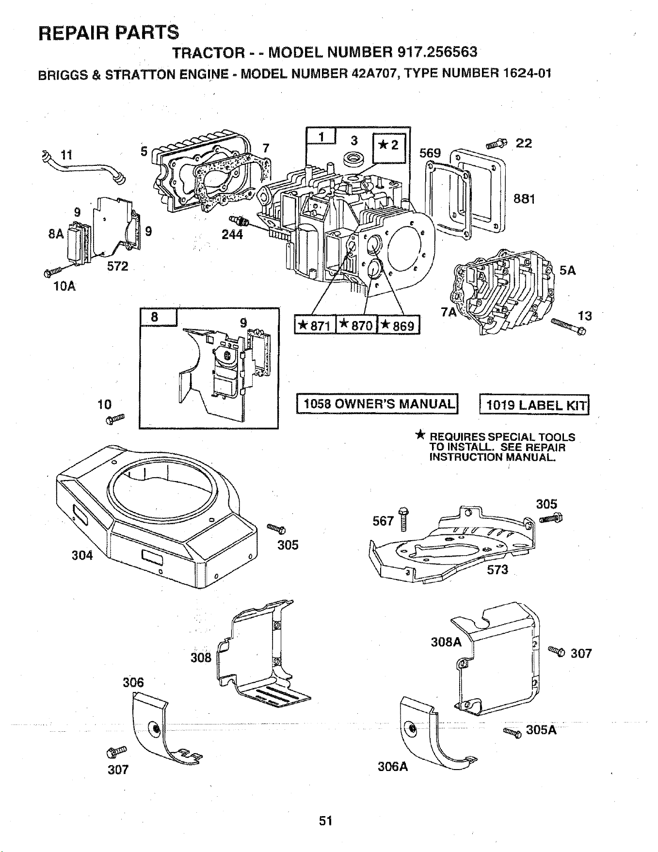
REPAIR PARTS
TRACTOR- = MODEL NUMBER 917.256563
BRIGGS & STRATTON ENGINE ° MODEL NUMBER 42A707, TYPE NUMBER 1624-01
• . = 3 _ 22
. ., °±__.. oo,
"_ REQUIRES SPECIAL TOOLS
TO INSTALL. SEE REPAIR
INSTRUCTION MANUAL.
_5
! 1019 LABEL KITI
305
307
308A
_) 307
305A
306A
51
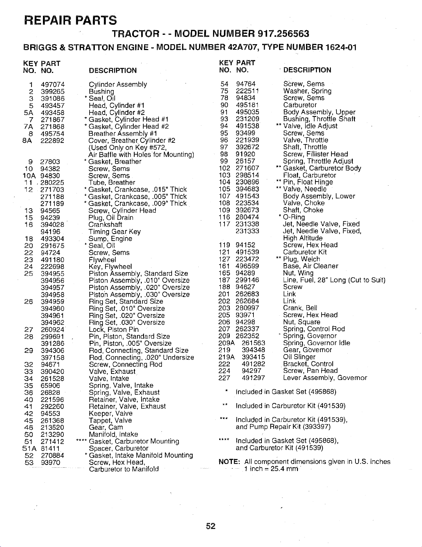
REPAIR PARTS
TRACTOR - - MODEL NUMBER 917.256563
BRIGGS & STRATTON ENGINE - MODEL NUMBER 42A707, TYPE NUMBER 1624-01
KEY PART KEY PART
NO. NO. DESCRIPTION NO, NO.
1 497074
2 399265
3 391086
5 493457
5A 493458
7 271867
7A 271868
8 495754
8A 222892
9 27803
10 94382
10A 94830
1 1 . 280225
12 271703
271188
271189
13 94565
15 94239
16 394028 "
94196
18 493304
20 291675
22 94724
23 491180
24 222698
25 394955
394956
394957
394958
26 394959
394960
394961
394962
27 260924
28 299691
391286
29 394306
397158
32 94671
33 390420
34 261528
35 65906
36 26828
40 221596
41 292260
42 94553
45 261368
46 213520
50 213290
51 271412
51A 81411
52 270884
53 93970
Cylinder Assembly
Bushing
* Sea!, Oil
Head, Cylinder #1
Head, Cylinder #2
* Gasket, Cylinder Head #1
* Gasket, Cylinder Head #2
Breather Assembly #1
Cover, Breathe[ Cylinder #2
(Used Only on Key #572,
Air Baffle with Holes'for Mounting)
* Gasket, Breather
Screw, Sems
Screw, Sems
Tube, Breather
* Gasket, Crankcase, .015" Thick
* Gasket, Crankcase, .005" Thick
* Gasket, Crankcase, °009"-I-hick
Screw, Cylinder Head
Plug, Oil Drain
Crankshaft
Timing Gear Key
Sump, Engine
* Seal, Oil
Screw, Sems
Flywheel
Key, Flywheel
Piston Assembly, Standard Size
Piston Assembly, .010" Oversize
Piston Assembly, .020" Oversize
Pisto'n Assembly, .030" Oversize
Ring Set, Standard Size
Ring Set, .010" Oversize
Ring Set, .020" Oversize
Ring Set, .030" Oversize
Lock, Piston Pin
Pin, Piston, Standard Size
Pin, Piston, .005" Oversize
Rod, Connecting, Standard Size
Rod, Connecting, .020" Undersize
Screw, Connecting Rod
Valve, Exhaust
Valve, Intake
Spring, Valve, Intake
Spring, Valve, Exhaust
Retainer, Valve, Intake
Retainer, Valve, Exhaust
Keeper, Valve
Tappet, Valve
Gear, Cam
Manifold, Intake
Gasket, Carburetor Mounting
Spacer, Carburetor
Gasket, Intake Manifold Mounting
Screw, Hex Head,
Carburetor to Manifold
DESCRIPTION
54 94764
75 222511
78 94834
90 495181
91 495036
93 231209
94 491538
95 93499
96 221939
97 392672
98 91920
99 26157
102 271607
103 298514
104 230896
105 394683
107 491543
108 223534
109 392673
116 280474
117 231338
231333
119 94152
121 491539
127 223472
161 496599
165 94289
187 299146
188 94627
201 262683
202 262684
203 280997
205 93971
206 94298
207 262337
209 262352
209A 261563
219 394348
219A 393415
222 491282
224 94297
227 491297
S_rew, Sems
Washer, Spring
Screw, Sems
Carburetor
Body Assembly, Upper
Bushing, Throttle Shaft
** Valve, idle Adjust
Screw, Sems
Valve, Throttle
Shaft, Throttle
Screw, Fiilister Head
Spring, Throttle Adjust
Gasket, carburetor Body
Float, Carburetor
Pin, Float Hinge
Valve, Needle
Body Assembly, Lower
Valve, Choke
Shaft, Choke
* O-Ring
Jet, Needle Valve, Fixed
Jet, Needle Valve, Fixed,
High Altitude
Screw, Hex Head
Carburetor Kit
** Plug, Welch
Base, Air Cleaner
Nut, Wing
Line, Fuel, 28" Long (Cut to Suit)
Screw
Link
Link
Crank, Bell
Screw, Hex Head
Nut, Square
Spring, Control Rod
" Spring, Governor
Spring, Governor Idle
Gear, Gbvernor
Oil Slinger
Bracket, Control
Screw, Pan Head
Lever Assembly, Governor
* Included in Gasket Set (495868)
** Inciuded in Carburetor Kit (491539)
*** Included in Carburetor Kit (491539),
and Pump Repair Kit (393397)
.... Included in Gasket Set (495868),
and Carburetor Kit (491539)
NOTE: All component dimensions given in U.S. inches
- 1 inch = 25.4 mm
52
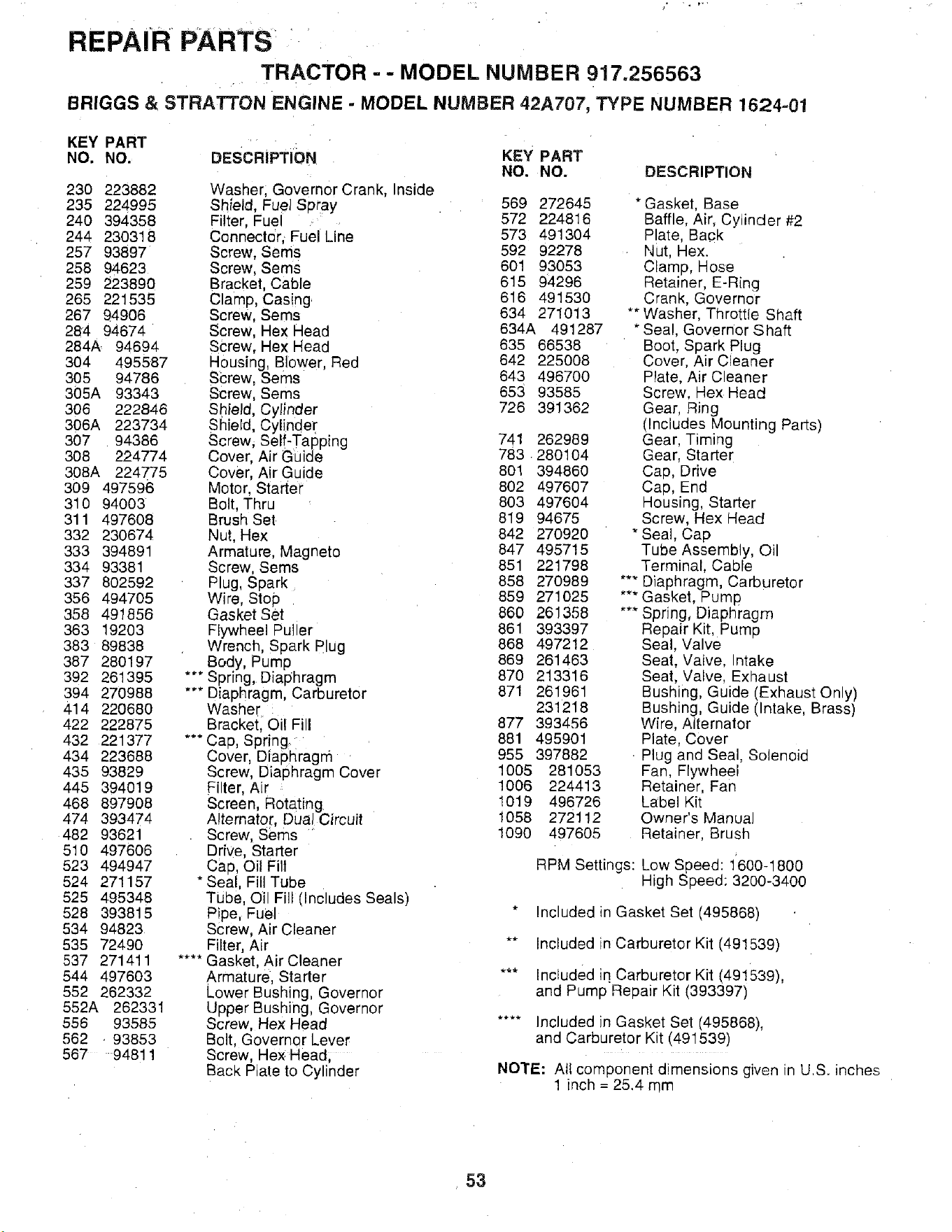
REPAIR PARTS
TRACTOR -- MODEL NUMBER 917.256563
BRIGGS & STRATTON ENGINE - MODEL NUMBER 42A707, TYPE NUMBER 1624-01
KEY PART KEY PART
NO. NO. DESCRIPTION
NO. NO. DESCRIPTION
230 223882 Washer, Governor Crank, Inside
235 224995 Shield, Fuel Spray 569 272645 * Gasket, Base
240 394358 Filter, Fuel 572 224816 Baffle, Air, Cylinder #2
244 230318 Connector, , Fuel Line 573 491304 Plate, Back
257 93897 Screw, Sems 592 92278 Nut, Hex.
258 94623 Screw, Sems 601 93053 Clamp, Hose
259 223890 Bracket Cable 615 94296 Retainer, E-Ring
265 221535 Clamp, Casing 616 491530 Crank, Governor
267 94906 Screw, Seres 634 271013 *'Washer, Throttie Shaft
284 94674 Screw, Hex Head 634A 491287 * Seal, Governor Shaft
284A 94694 SCrew, Hex Head 635 66538 Boot, Spark Plug
304 495587 Housing, Blower. Red 642 225008 Cover, Air Cleaner
305 94786 SCrew, Seres 643 496700 Plate, Air Cleaner
305A 93343 Screw, Sems 653 93585 Screw, Hex Head
306 222846 Shield, Cylinder 726 391362 Gear, Ring
(Includes Mounting Parts)
306A 223734 Shield, Cylinder
307 94386 Screw, Self-Tapping 741 262989 Gear, Timing
308 224774 Cover, Air Guide 783 280104 Gear, Starter
308A 224775 Cover, Air Guide 801 394860 Cap, Drive
309 497596 Motor. Starter 802 497607 Cap, End
310 94003 Bolt. Thru 803 497604 Housing, Starter
311 497608 Brush Set 819 94675 Screw, Hex Head
332 230674 Nut, Hex 842 270920 * Seal, Cap
333 394891 Armature, Magneto 847 495715 Tube Assembly, Oil
334 93381 Screw, Sems 851 221798 Terminal, Cable
337 802592 Plug, Spark 858 270989 **" Diaphragm, Carburetor
356 494705 Wire. Stop 859 271025 *** Gasket, Pump
358 491850 Gasket Set 860 261358 *** Spring, Diaphragm
363 19203 Flywheel Pul er 861 393397 Repair Kit, Pump
383 89838 Wrench, Spark Plug 868 497212 Seal, Valve
' 869 261463 Seat, Valve, Intake
387 280197 Body, Pump
392 261395 *** Spring, Diaphragm 870 213316 Seat, Valve, Exhaust
394 270988 *** Diaphragm, Carburetor 871 261961 Bushing, Guide (Exhaust OnLy)
231218 Bushing, Guide (Intake, Brass)
414 220680 Washer .
422 222875 Bracket, Oil Fill 877 393456 Wire, Alternator
881 495901 Plate, Cover
432 221377 "** Cap, Spring. '
434 223688 Cover Diaphragm 955 397882 • Plug and Seal, Solenoid
435 93829 Screw, Diaphragm Cover 1005 281053 Fan, Flywheel
1006 224413 Retainer, Fan
445 394019 Filter, Air 1019 496726 Label Kit
468 897908 Screen, Rotating.
474 393474 Alternator, Dual Circuit 1058 272112 Owner's Manual
482 93621 Screw, seres 1090 497605 Retainer, Brush
510 497606 Drive, Starter
523 494947 Cap, Oil Filt RPM Settings: Low Speed: 1'600-1800
524 271157 * Seal, Fill Tube High Speed: 3200-3400
525 495348 Tube, Oil Fill (Includes Seals)
528 393815 Pipe, Fuel * Included in Gasket Set (495868)
534 94823 Screw, Air Cleaner
535 72490 Filter, Air ** Included in Carburetor Kit (491539)
537 271411 .... Gasket, Air Cleaner
544 497603 Armature, Starter *** IncLuded iq Carburetor Kit (491539),
552 262332 Lower Bushing, Governor and Pump Repair Kit (393397)
552A 262331 Upper Bushing, Governor
556 93585 Screw, Hex Head .... Included in Gasket Set (495868),
562 . 93853 Bolt, Governor Lever and Carburetor Kit (491539)
567 94811 Screw, He× Head,
Back Plate to Cylinder NOTE: All component dimensions given in U.S. inches
1 inch = 25.4 mm
53

SERVICE NOTES
.... ir i¸ , ----
54

SUGGESTED GUIDE FOR SIGHTING SLOPES FOR SAFE OPERATION
01
ol
"T
SIGHTING
---.. ot -ou .°
_'H__s'_v _o_n.
ONLY RIDE UP AND DOWN HILL,
NOT ACROSS HiLL
SIGHT AND HOLD THIS LEVEL WITH
SKY LINE OR TREE.
15 ° MAX.
1
Operate your Tractor up and down the face of slopes (not
greater than 15°), never across the face, Make turns gradu-
ally to prevent tipping or loss of control. Exercise extreme
caution when changing direction on slopes,

SEARS
OWNER'S
MANUAL
MODEL NO.
917.256563
IF YOU NEED
REPAIR SERVICE
OR PARTS:
FOR REPAIR SERVICE, CALL
THIS TOLL FREE NUMBER:
1-800-4-REPAIR
(1-800-473-7247)
FOR REPLACEMENT PARTS
INFORMATION AND
ORDERING, CALL THIS
TOLL FREE NUMBER:
1-800-FON-PART
(1-800-366-7278)
FOR CONSUMER ASSISTANCE
HOT LINE, CALL THIS
TOLL FREE NUMBER:
1-800-659-5917
CRAFTXMAN®
19.0 HP TWIN CYLINDER
ELECTRIC START
42" MOWER
6 SPEED TRANSAXLE
LAWN TRACTOR
Each tractor has its own model number. Each engine has
its own model number.
The model number for your tractor will be found on the
model plate located under the seat.
The model number for your engine will be found on the
blower housing of the engine.
All parts listed herein may be ordered from any Sears,
Roebuck and Co. Service Center/Department and most Re-
tail Stores.
WHEN ORDERING REPAIR PARTS, ALWAYS GIVE THE
FOLLOWING INFORMATION:
• PRODUCT - TRACTOR
* MODEL NUMBER- 917.256563
• ENGINE MODEL NO. -42A707, TYPE NO. 1624-01
,, PART NUMBER
, PART DESCRIPTION
Your Sears merchandise has added value when you
consider Sears has service units nationwide staffed with
Sears trained technicians.., professional technicians
specifically trained to insure that we meet our pledge to
you, we service what we sell.
155159 5.9.96 JH Printed in U.S.A.


