Loading ...
Loading ...
Loading ...
Safety Instructions Operating Instructions Care and Cleaning Installation Instructions Troubleshooting Tips Customer Service
Read these instructions completely and carefully.
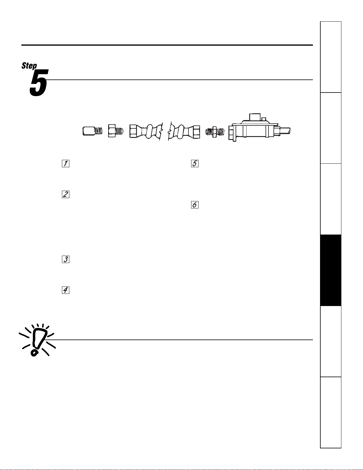
Connect the Range to Gas
The house piping and connector used to connect the range to the main gas supply must be
clean, free of metal shavings, rust, dirt or liquids (oil or water). Contaminants in the supply lines
can work their way into the range manifold and cause failure of gas valves or controls and clog
burners or pilot orifices.
If the range is to be connected to house
piping with flexible or semi-rigid metal
appliance connector, connector nuts
MUST
NOT
be connected directly to pipe threads.
The appliance connector must be installed
by using the proper flare union adapters with
the connector. Cutoff valve, appliance
connector and adapters are not supplied
with the range. (Because solid pipe restricts
moving the range, we recommend use of
A.G.A. certified flexible tubing.) In Canada,
flexible connectors must be single wall metal
connectors no longer than 6 feet in length.
Install a manual shutoff valve in the gas line
in an easily accessible location outside of the
range. Be sure you know how and where to
shut off the gas supply to the range.
Check for leaks. After connecting the range
to gas, check the system for leaks with a liquid
leak detector at all joints and connections.
Tighten all connections as necessary to
prevent gas leakage in the range or supply
line.
CAUTION: Do not use a flame to check for
gas leaks.
Check alignment of valves after connecting
the range to the gas supply to be sure the
manifold pipe has not been moved. A
misalignment could cause the valve knob
stem to rub on the control panel, resulting in
a gas leak at the valve.
Disconnect the range and its individual shut-off
valve from the gas supply piping system during
any pressure testing of the system at test pressures
greater than 1/2 psig.
Isolate the range from the gas supply piping
system by closing its individual manual shut-off
valve during any pressure testing of the gas supply
piping system at test pressures equal to or less
than 1/2 psig.
29
House
piping
Flare union
adapter
Flare union
adapter
Range pressure
regulator
Appliance
connector
Nut Nut
Checking Manifold Gas Pressure
If it should be necessary to check the manifold gas
pressure, connect manometer (water gauge) or
other pressure device to the top burner orifice
farthest from the manifold inlet and turn burner
valve on.
For an accurate pressure check have at least
2 other top burners burning. Be sure the gas
supply inlet pressure is at least one inch above
specified range manifold pressure.
The gas supply pressure should never be over
14 inches W.C. When properly adjusted for
Natural Gas the W.C. pressure is 4 inches; for LP
Gas the W.C. pressure is 10 inches. The serial
plate, located under the main top in the burner
box area, indicates for which type of gas your
range was factory adjusted.
Loading ...
Loading ...
Loading ...