Loading ...
Loading ...
Loading ...
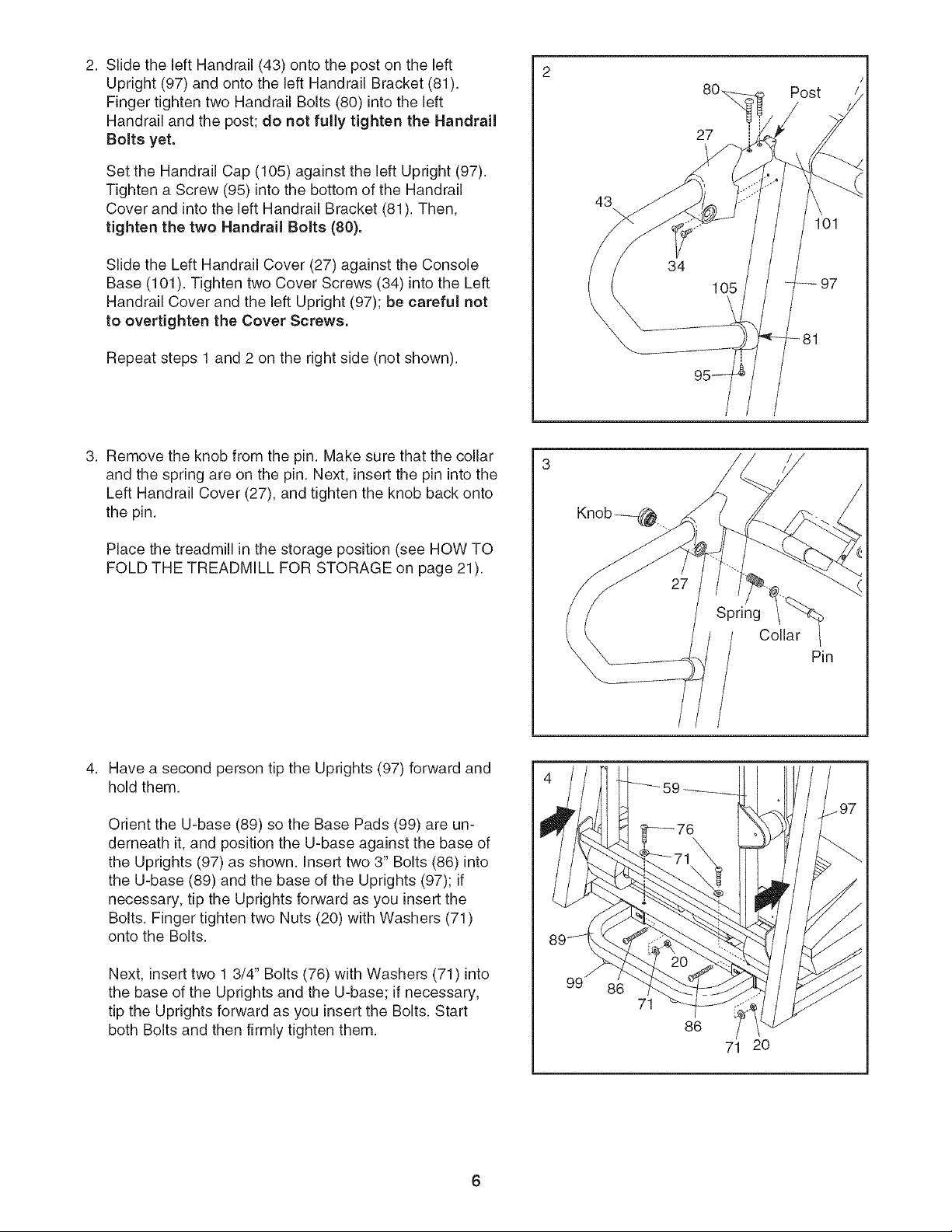
2. SlidetheleftHandrail(43)ontothepostontheleft
Upright(97)andontotheleftHandrailBracket(81).
FingertightentwoHandrailBolts(80)intotheleft
Handrailandthepost;do notfully tightentheHandrail
Boltsyet.
SettheHandrailCap(105)againsttheleftUpright(97).
Tightena Screw(95)intothebottomoftheHandrail
CoverandintotheleftHandrailBracket(81).Then,
tightenthetwoHandrailBolts(80).
SlidetheLeftHandrailCover(27)againsttheConsole
Base(101).TightentwoCoverScrews(34)intotheLeft
HandrailCoverandtheleftUpright(97);becarefulnot
to overtightentheCoverScrews.
Repeatsteps1 and2 ontherightside(notshown).
43
\
27
97
3. Remove the knob from the pin. Make sure that the collar
and the spring are on the pin. Next, insert the pin into the
Left Handrail Cover (27), and tighten the knob back onto
the pin.
Place the treadmill in the storage position (see HOW TO
FOLD THE TREADMILL FOR STORAGE on page 21).
Spring
Collar
Have a second person tip the Uprights (97) forward and
hold them.
Orient the U-base (89) so the Base Pads (99) are un-
derneath it, and position the U-base against the base of
the Uprights (97) as shown. Insert two 3" Bolts (86) into
the U-base (89) and the base of the Uprights (97); if
necessary, tip the Uprights forward as you insert the
Bolts. Finger tighten two Nuts (20) with Washers (71)
onto the Bolts.
Next, insert two 1 3/4" Bolts (76) with Washers (71) into
the base of the Uprights and the U-base; if necessary,
tip the Uprights forward as you insert the Bolts. Start
both Bolts and then firmly tighten them.
71
86
71 2O
V
Loading ...
Loading ...
Loading ...