
SWAINS
®
MODEL
917.259541 OWNER'S MANUAL
° Assembly
° Operation
° Customer Responsibilities
° Service and Adjustments
Repair Parts
CAUTION: Read and follow all safety rules and instructions before operating this equipment.
FOR CONSUMER ASSISTANCE HOT LINE, CALL THIS TOLL FREE NUMBER: 1-800-659-5917
IIIIIIIIIIIIIHIII

SAFETY RULES
Safe Operation Practices for Ride-On Mowers
IMPORTANT: THIS CUTTING MACHINE fS CAPABLE OF AMPUTATING HANDS AND FEET AND THROWING OBJECTS
FAILURE TO OBSERVE THE FOLLOWING SAFETY INSTRUCTIONS COULD RESULT IN SERIOUS INJURY OR DEATH
1. GENERAL OPERATION
• Read, understand, and follow all instructions in the manual
and on the machine before starting,
• Only atiow responsible adults, who are familiar with the
instructions, to operate the machine
• Clear the area of objects such as rocks, toys, wire, etc,
which could be picked up and thrown by the blade
• Be sure ihe area isclear of other people before mowing Stop
machine if anyone enters the area
Never carry passengers
Do no! mow in reverse unless absolutely necessary Always
look down and behind before and while backing,,
• Be aware of the mower discharge dilection and do not point
it at anyone. Do not operate the mower without either the
entire grass catcher or the guard in place
• Stow down before turning,
° Never leave a running machine unattended. Always turn off
blades, set parking brake, stop engine, and remove keys
before dismounting
° Turn elf blades when not mowing
• SLop engine before removing grass catcher or unclogging
chuie
Mow only in daylight or good artificial light,
Do not operaie the machine while under the infiuence of
alcohol or drugs
. Watch for traffic when operating near or crossing roadways,
• Use extra care when foRding or unbadlng the machine into
a trailer or truck
II. SLOPE OPERATION
Slopes are a major factor related to loss-of-control and
tipover accidents, which can result in severe injury ordeath.
All slopes require extra caution. If you cannot back up the
slope or if you feel uneasy on it, do not mow it..
DO:
• Mow up and down stopes, not acros s.
• Remove obstacles such as rocks, tree limbsl etc
Watch for hobs, ruts, or bumps, Uneven ierrain could
overturn the machine. Tall grass can hide obstacles
• Use slow speed.. Choose atowgear so that you will not have
to slop or shill while on the slope
• Follow the manufacturer's recommendations for wheel
weights or counterweights to improve stability.
• Use exlra care wilh grass catchers oi' other attachments
These can change the stability of the machine.
• Keep all movement on the slopes slow and gradual Do not
make sudden changes in speed or direction
• Avoid starting or stopping on a slope. If liras lose traction,
disengage the blades and proceed slowly straight down the
slope
DO NOT:
Do not lurn on slopes unless necessary, and then, turn slowly
and gradually downhill, if possible.
• Do not mow near drop-otis, ditches, or embankments. The
mower could suddenly turn over if a wheel is over the edge
of a cliff or ditch, or if an edge caves in.
• Do not mow on wet grass, Reduced traction could cause
sliding..
• De not iry to stabilize the machine by putting your foot on the
ground
• Do not use grass catcher on steep slopes..
IIL CHILDREN
Tragic accidents can occur if the operator is not alert to the
presence of children Children are often attracted to the
machine and the mowing activity, Never assume that
children wi!l remain where you last saw them.
• Keep children out of the mowing area and under the watchful
care of another responsible adut!
• Be alert and turn machine off if children enter lhe area
• Before and when backing, look behind and down for' small
children
,, Never carry children They may fall otf and be seriously
injured or intedere with safe machine operation
• Never allow children to operate the machine..
• Use extra care when approaching blind corners, shrubs,
trees, or other objects that may obscure vision
IV. SERVICE
" Use extra care in handling gasoline and other fuels, They are
flammable and vapors are explosive
Use only an approved container
Never remove gas cap or add fuel with the engine
running.. Allow engine to cool before refueling Do not
smoke
Never refuel the machine indoors
Never slore the machine or fuel container inside where
there is an open flame, such as a water heater
• Never run a machine inside a closed area
• Keep nuts and bolts, especially blade attachment bolts, tight
and keep equipment in good condition
• Never tamper with safety devices, Check their proper
operation regularly
• Keep machine free of grass, leaves, or other debris build-up
Clean oil or fuel spillage Allow machine to cool before
storing,.
• Stop and inspect the equipment il you strike an objecL
Repair, if necessary, before restarling
• Never make adjustmenls or repairs with the engine running,
• Grass catcher components are subjeci towear, damage, and
deterioration, which could expose moving paris or allow
objects to be thrown. Frequently check components and
replace with manulacturer's recommended pads, when nec-
essary
• Mower blades are sharp and can cut,. Wrap the blade(s) or
wear gloves, and use extra caution when servicing them
" Check brake operation frequently, Adjust and service as
required.
H i HmHN,ll mH,,,,,I I I J
Look for this symbol to point out im.
!
portent safety precautions. It means
CAUTION!!! BECOMEALERT!!! YOUR
SAFETY IS INVOLVED.
ill
The engine exhaust from this product con-
tains cl'iemicals known to the State of Califor-
nia to cause cancer, birth defects, or other
reproductive harm.
,,i,J,i i i imml iHll ill

CONGRATULATIONS on your purchase of a Sears
Tractor. It has been designed, engineered and manufac-
tured to give you the best possible dependability and
performance.
Should you experience any problem you cannot easily
remedy, please contact your nearest Sears Authorized
Service CentedDepartmenL We have competent, well-
trained technicians and the proper tools to service or repair
this tractor.
Please read and retain this manual. The instructions will
enable you to assemble and maintain your tractor properly.
Always observe the "SAFETY RULES"°
MODEL
NUMBER 917 259541
SERIAL
NUMBER
DATE OF PURCHASE
THE MODEL AND SERIAL NUMBERSWILLBE FOUND
ON A PLATE UNDER THE SEAT.
YOU SHOULD RECORD BOTH SERIAL NUMBER AND
DATE OF PURCHASE AND KEEP IN A SAFE PLACE
FOR FUTURE REFERENCE,
MAINTENANCE AGREEMENT
A Sears Maintenance Agreement is available on this prod-
uct, Contact your nearest Sears store for details,
CUSTOMER RESPONSIBILITIES
• Read and observe the safety rules.
. Follow a regular schedule in maintaining, caring for and
using your tractor.
. Follow the instructions under "Customer Responsibili-
ties" and "Storage" sections of this owner's manual.
PRODUCT SPECIFICATIONS
HORSEPOWER: 15.5
iGASOLINE CAPACITY 125 GALLONS
ANw...D TYPE: UNLEADED REGULAR
OIL TYPE (API-SF/SG/SH): SAE 10W30 (above 32°F)
SAE 5W-30 (below 32 F)
OlL CAPACITY: W/FILTER: 4.0 PINTS
W/O FILTER: 3.5 PINTS
SPARK PLUG: CHAMPION RC12YC
(GAP: ,040")
VALVE CLEARANCE: NOT ADJUSTABLE
GROUND SPEED (MPH): FORWARD:
1st 1,,1
2rid 1,5
3rd 2,3
41h 35
5th 4 4
6th 57
REVERSE: 1.7
TIRE PRESSURE: FRONT: 14 PSI
REAR: 10 PSI
CHARGING SYSTEM: 3 AMPS BATTERY
5 AMPS HEADLIGHTS
BATTERY: AMP/HR: 30
MIN. CCA: 240
CASE SIZE: U1R
BLADE BOLT TORQUE: 30-35 FT' LBS
WARNING: This tractor is equipped with an internal
combustion engine and should not be used on or near any
unimproved forest-covered, brush-covered or grass-cov-
ered land unless the engine's exhaust system is equipped
with a spark arrester meeting applicable local or state laws
(if any).. If a spark arrester is used, it should be maintained
in effective working order by the operator.
In the state of California the above is required by law
(Section 4442 of the California Public Resources Code),
Other states may have similar laws_ Federal taws apply on
federal lands. A spark arrester for the muffler is available
through your nearest Sears Authorized Service Center!
Department (See REPAIR PARTS section of this manual),
,,, i
IL....................
LIMITED TWO YEAR WARRANTY ON CRAFTSMAN RIDING EQUIPMENT
For two (2) years from the date of purchase, if this Craftsman Riding Equipment is maintained, lubricated and tuned up according to
the instructions in the owner's manual, Sears will repair or replace, free of charge, any parts found to be defective in material or
workmanship.
This Warranty does not cover:
- Expendable items which become worn during normal use, such as blades, spark plugs, air cleaners, belts, etc
• Tire replacement or repair caused by punctures from ou!side objects, such as nails, thorns, stumps, or glass
• Repairs necessary because of operator abuse, negligence, improper storage or accident or the failure to maintain the
equipment according to the instructions contained in the owner's manual
• Riding equipment used for commercial or rental purposes.
LIMITED 90 DAY WARRANTY ON BATTERY
For ninety (90) days from date of purchase, if any battery included with this riding equipment proves defective in material or
workmanship and our testing determines the battery will not hold a charge, Sears will replace the battery at no charge.
IN-HOME WARRANTY SERVICE ON YOUR CRAFTSMAN RICING EQUIPMENT IS AVAILABLE AT NO-CHARGE FOR 30 DAYS
FROM THE DATE OF PURCHASE. PLEASE CONTACT YOUR NEAREST SERVICE CENTER. AFTER 30 DAYS FROM THE
DATE OF PURCHASE, WARRANTY SERVICE IS AVAILABLE BY TAKING YOUR CRAFTSMAN RIDING EQUIPMENT TO YOUR
NEAREST SEARS SERVICE CENTER. (IN-HOME WARRANTY SERVICE WILL STILL BE AVAILABLE AFTER 30 DAYS FROM
THE DATE OF PURCHASE BUT A STANDARD TRIP CHARGE WILL APPLY.) THIS WARRANTY APPLIES ONLY WHILE THIS
PRODUCT IS IN THE UNITED STATES.
This Warranty gives you specific legal rights, and you may also have other rights which may vary from state to state..
SEARS, ROEBUCK AND CO,, D/817 WA, HOFFMAN ESTATES, IL 60179

TABLE OF CONTENTS
SAFETY RULES ............................................................ 2
PRODUCT SPECIFICATIONS ...................................... 3
CUSTOMER RESPONSIBILITIES ..................... 3, 15-19
WARRANTY .................................................................. 3
TABLE OF CONTENTS ................................................ 4
ASSEMBLY ................................................................ 7-9
OPERATION ............... ............................................ 10-14
MAINTENANCE SCHEDULE ...................................... 15
SERVICE AND ADJUSTMENTS ............................ 20-25
STORAGE ................................................................... 26
TROUBLESHOOTING ............................................ 27-28
REPAIR PARTS - TRACTOR ................................. 30-47
REPAIR PARTS - ENGINE .................................... 48-53
PARTS ORDERING/SERVICE .................. BACK PAGE
iNDEX
A
Accessories ............. :.................... 5
Adjuslments:
Brake ...................................... 22
Carburetor ...................................... 25
Mower:
Front-To-Back ........................ 21
Side-To-Side .......................... 21
Throttle Control Cable ......................25
Air Filter, Engine .................................. 18
Air Screen, Engine ............................. 18
Assembly ......................................... 7.9
B
Battery:
Charging ................................ 7
Cleaning ....................................... 16
Starting with Weak Battery ......... 23
Storage .......................................... 26
Terminals ..................................... 16
Belts:
Motion Drive
Removal/Replacement .......... 22
Mower Blade Drive
RemovalfReplacement .......... 22
Blade:
Sharpening ................................ !6
Replacement ................................ !6
Brake Adiustment ................................ 22
C
Carburetor Adjustment ....................... 25
Controls, Tractor .............................. 11
Customer Responsibilities ............ 15-19
Engine:
Air Filter .................................. 18
Air Screen, Engine .................. 18
Battery .................................... t 7
Cooling Fins, Engine ............... 18
Engine OIl ............................... 17
Fuel Filter ................................ 19
Spark Plugs ............................. 18
Tractor:
Blades ....................................... 16
Lubrication Chart .................... 15
Maintenance Schedule .......... 15
Tire Care ......................... 9,16,23
Cutting Height, Mower ......................... 12
E
Electrical:
Interlocks and Relays ................. 24
Schematic ...................................... 29
Wiring Diagram ........................... 30
Engine:
Air Filter. ....................................... 18
Atr Screen ...................................... 18
Cooling Fins, Engine ......................18
OIl Change ................................... 17
OIl Level ..................................... 13,17
Oil Type .......................................... t 7
Preparation ................................. 13
Repair Parts ......................... 48-53
Starting ....................................... 14
Storage .............................................26
F
Filters:
Air ................................................ 18
Fuel .......................................... 19
Fuel:
Type ........................................... 13
Storage ............................................26
Fuse .....................................................24
G
Gauge Wheels ...................................... 8
H
Hood Removaltlnstallation .................. 24
L
Leveling Mower Deck ........................ 21
Lubrication Chart ................................ 15
M
Maintenance Schedule ....................... 15
Mower:
Adjustment, Front-to-Back .......... 21
Adjustment, Stde.,to.Slde ............ 21
Blade Sharpening ...................... 16
Blade Replacement .................... 16
Cutting Height .............................. 12
Instaitatlon .................................... 20
Operation ...................................... 13
Removal ...................................... 20
Mowing Tips ........................................ 14
Muffler ................................................ 18
Spark Arrestor ............................3,40
Mulcher Plate ...................................... 9
O
Oi1:
Cold Weather Conditions ....... 14,17
Engine ........................................17
Storage ....................................... 26
Operation .................................. 10-t 4
Operating Mower ......................... t3
Options:
Accessories .................................... 5
Spark Arrester ...................... 3,40
P
Parking Brake .............................. t 1-12
PartsBag ......................................................6
Parts, Replacement/Repair ...........30-47
Product Specifications ....................... 3
R
Repair Paris ............................... 30-47
S
Safely Rules ........................... 2
Seat .................................................. 8
Service and Adjustments ............ 20-25
Brake ............................................. 22
Carburetor ..................................... 25
Fuse ..............................................24
Hood Removaltlnstaflation .......... 24
Motion Drive Belt
Removat/Replacemenl .......... 22
Mower Blade Drive Belt
Removal/Replacement ......... 22
Mower Adjustment:
Front-to-Back ........................ 21
Side-to-Side ................. 21
Mower Installation ................... 20
Mower Removal ........................ 20
Tire Care ........................... 9,!6,23
Slope Guide Sheet .............................. 55
Spark Plugs ....................................... 18
Specifications ......................................... 3
Starting the Engine ......................... 13.14
Steering Wheel ................................ 7,23
Stopping the Tractor .......................... 12
Storage ......................................... 26
T
Throttle Control Cable Adjustment .... 25
Tires ........................................ 9,16,23
Trouble Shooting Chart ............. 27-28
Transaxle Repair Paris .............. 46-47
W
Warranty ................................................. 3
Wiring Diagram ................................... 30
Wiring Schematic ................................ 29
4
.................................................... i ........................... i uu,L
ACCESSORIES AND ATTACHMENTS
These accessories and attachments were available through most Sears retail outlets and service centers when the tractor was purchased
Most Sears stores can order these items for you when you provide the model number of your tractor
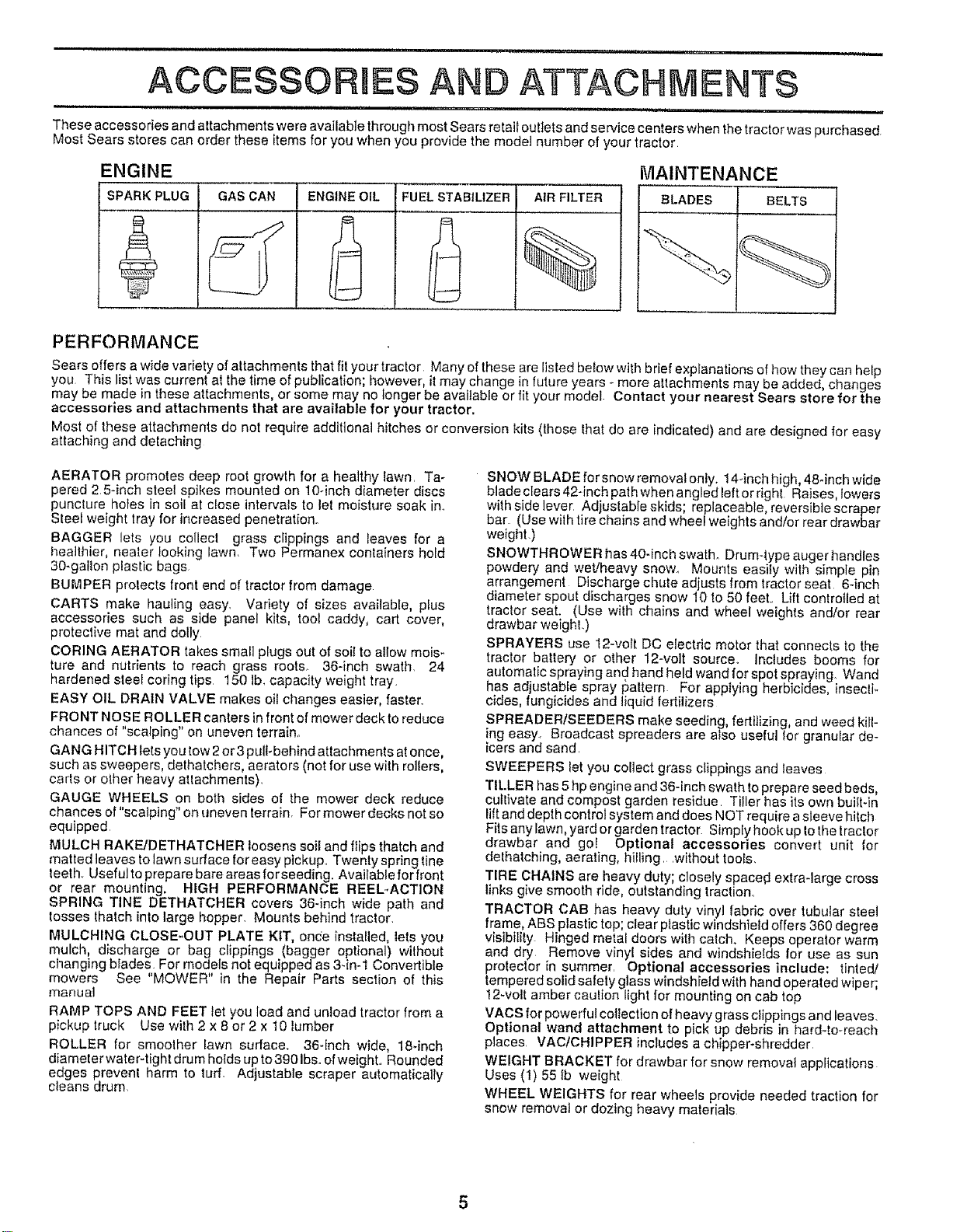
ENGINE MAINTENANCE
SPARK PLUG GAS CAN ENGINEOIL FUEL STABILIZER AIR FILTER BLADES BELTS
PERFORMANCE
Sears offers a wide variety of attachments that fit your tractor Many of these are listed below with brief exp anations of how they can help
you Ti_is list was current at the time of publication; however itmay change in future years - more attachments may be added, changes
may be made n these attachments, or some may no longer be available or fit your model Contact your nearest Sears store for the
accessories and attachments that are available for your tractor.
Most of these attachmenls do not require additional hitches or conversion kits (those that do are indicated) and are designed for easy
attaching and detaching
AERATOR promotes deep root growth for a healthy lawn, Ta-
pered 2 5*inch steel spikes mounted on 10-inch diameter discs
puncture holes in soil at c!ose intervals to let moisture soak in_
Steel weight tray for increased penetration°
BAGGER lets you collecl grass clippings and leaves for a
healthier, nealer looking lawn_ Two Permanex containers hold
30-gallon plastic bags
BUMPER prelects front end of tractor from damage
CARTS make hauling easy, Variety of sizes available, plus
accessories such as side panel kits, tool caddy, cart cover,
protective mat and dolly
CORING AERATOR takes small plugs out of soil to allow mois-
ture and nutrienls to reach grass roots_ 36-inch swath. 24
hardened sleet coring tips 150 lb_capacity weight tray,
EASY OIL DRAIN VALVE makes oil changes easier, faster.
FRONT NOSE ROLLER canters in front of mower deck to reduce
chances of "scalping" on uneven terrain,
GANG HITCH lets you tow2 or 3puli-behlnd attachments atonce,
such as sweepers, dethatchers, aerators (not for use with rolIers,
carts or other heavy atlachments),
GAUGE WHEELS on both sides of the mower deck reduce
chances of "scalping" on uneven terrain, For mower decks not so
equipped
MULCH RAKE/DETHATCHER loosens soil and flips thatch and
matted leaves to lawn surface for easy pickup,, Twenty spring line
leeth. Useful to prepare bare areas forseeding, Available for front
or rear mounting. HIGH PERFORMANCE REEL-ACTION
SPRING TINE DETHATCHER covers 36-inch wide path and
tosses lhatch info large hopper, Mounts behind tractor,
MULCHING CLOSE-OUT PLATE KIT, once installed, lets you
mulch, discharge or bag clippings (bagger optional) without
changing blades For models not equipped as 3-in-1 Convertible
mowers See "MOWER" in the Repair Parts section of this
manual
RAMP TOPS AND FEET let you load and unload tractor from a
pickup truck Use with 2 x 8 or 2 x t0 lumber
ROLLER for smoother lawn surface, 36-inch wide, t8qnch
diameterwater-tight drum holds upto3901bs, ofweight., Rounded
edges prevent harm to turf. Adjustable scraper automatically
cleans drum
SNOW BLADE for snow removal only. 14÷inch high, 48qnch wide
bladeclears42-inchpalhwhenangledleftorright Raises, lowers
with side lever Adjustable skids; replaceable, reversible scraper
bar (Use with tire chains and wheel weights and/or rear drawbar
weight.)
SNOWTHROWER has 40-inch swath° Drum-type auger handles
powdery and wet/heavy snow° Mounts easily with simple pin
arrangement Discharge chute adjusts from tractor seat 6-inch
diameter spout discharges snow 10 !o 50 feet,, Lift controlled at
tractor seat. (Use with chains and wheel weights and/or rear
drawbar weight.)
SPRAYERS use 12-volt DC electric motor that connects to the
tractor battery or other 12-volt source Includes booms for
automatic spraying and hand held wand for spot spraying. Wand
has adjustable spray f3attern For applying herbicides insecfi-
cides, lung c des and liquid fertilizers
SPREADERISEEDERS make seeding, fertilizing, and weed kill-
ing easy, Broadcast spreaders are also useful Ior granular de-
icers and sand,
SWEEPERS let you collect grass clippings and leaves
TILLER has 5hp engine and 36-inch swath to prepare seed beds,
cultivate and compost garden residue Tiller has its own built-in
lift and depth control system and does NOT require asleeve hitch
Fits any lawn, yard or garden tractor. Simply hook up io the tractor
drawbar and go! Optional accessories convert unit for
delhatching, aerating, hilling, ,without tools.
TIRE CHAINS are heavy duty; closely spaced extra-large cross
links give smooth ride, outstanding traction.,
TRACTOR CAB has heavy duly vinyl fabric over tubular steel
frame, ABS plastic top; clear plastic windshield offers 360 degree
visibility. Hinged metal doors with catch. Keeps operator warm
and dry Remove vinyl sides and windshields for use as sun
protector [n summer, Optional accessories include: tinted/
tempered solid safety glass windshield with hand operated wiper
12-volt amber cau ion Ight for mounting on cab lop
VACS for powerful collection of heavy grass clippings and leaves,
Optional wand attachment to pick up debris in hard-to-reach
places, VACtCHIPPER includes a chipper-shredder
WEIGHT BRACKET for drawbar for snow removal applications
Uses (1) 55 lb weight
WHEEL WEIGHTS for rear wheels provide needed traction for
snow removal or dozing heavy materials
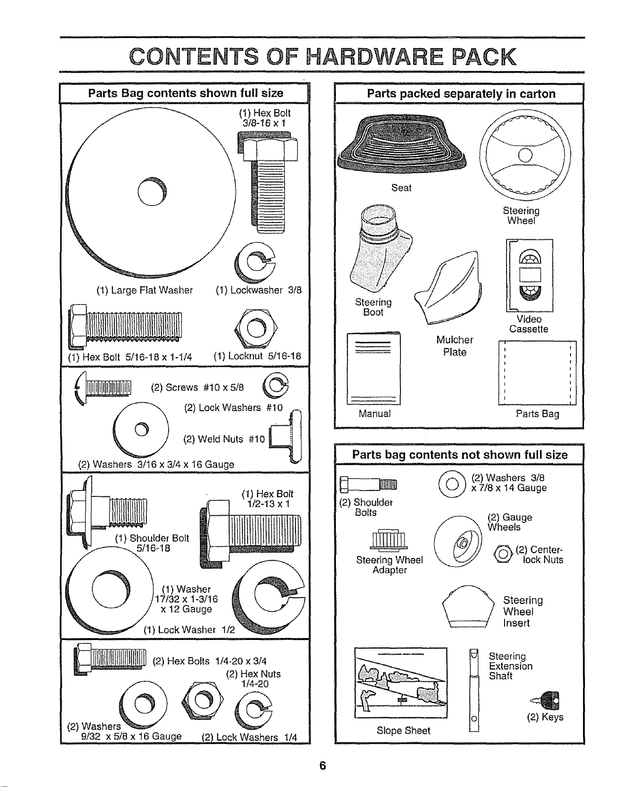
©
(1) Large Flat Washer
©
(1) Lockwasher 3/8
(1) Hex Bolt 5/16q8 x 1-1/4 (1) Locknut 5/16-18
(2) Screws #10 x 5/8
(2) Lock Washers #10 -.
(2) Weld Nuts #10 _ I
J
,,, (2) Washers 3/16 X 3,/4,x !6 Gauge
(t) Hex Bolt
112-13 x 1
(1) Shoulder Bolt
5/16_18
1) Washer
x 1-3/16
x 12 Gauge
Seat
Steering
Boot
Manual
u,
Mulcher
Plate
Steering
Wheel
Video
Cassette
Parts Bag
inn, i1,11
Parts bag contents not shown full size
...................... i mHHHH Hn,
_ (2) Washers 3/8x 7/8 x 14 Gauge
(2) Shoulder
Bolts
Steering Wheel
Adapter
(2) Gauge
Wheels
(2) Center-
lock Nuts
Steering
Wheel
Insert
Slope Sheet
Steering
Extension
Shaft
(2) Keys
6
ASSEMBLY
i ,., i .nuul i ,.lU i ...............i..... n,, i, , i,,, H,,i
Your new tractor has been assembled at the factory with exception of those parts left unassembled for shipping purposes.
To ensure safe and proper operation of your tractor alf parts and hardware you assemble must be tightened securely.. Use
the correct tools as necessary to insure proper tightness.
TOOLS REQUIRED FOR ASSEMBLY
A socket wrench set will make assembly easier, Standard
wrench sizes are listed°
(2) 7/16" wrenches Tire pressure gauge
(2) 1/2" wrenches Phillips screwddver
(I) 9/16" wrench Utiiity knife
(1) 3/4" socket with drive ratchet
When dght or left hand is mentioned in this manual, it
means when you are in the operating position (seated
behind the steering wheel).
TO REMOVE TRACTOR FROM CARTON
UNPACKCARTON
• Remove all accessible loose parts and parts cartons
from carton (See page 2).
• Cut, from top to bottom, along lines on all four corners
of carton, and lay panels fiaL
o Check for any additional loose parts or cartons and
BEFORE ROLLING TRACTOR OFF SKID
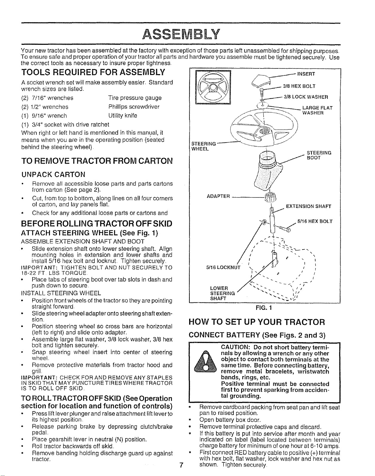
ATTACH STEERING WHEEL (See Fig. 1)
ASSEMBLE EXTENSION SHAFT AND BOOT
• Slide extension shaft onto lower steering shaft. Align
mounting holes in extension and lower shafts and
install 5/16 hex bolt and locknut, Tighten securely,
iMPORTANT: TIGHTEN BOLT AND NUT SECURELY TO
18-22 FT LBSTORQUE
• Place tabs of steering boot over tab slots in dash and
push down to secure_
iNSTALL STEERING WHEEL
• Position front wheels of the tractor so they are pointing
straight forward
° Slide steering wheel adapter onto steering shaft exten-
sion.
• Position steering wheel so cross bars are horizontal
(left to right) and slide onto adapter°
• Assemble large flat washer, 3/8 lock washer, 3/8 hex
bolt and tighten securely°
- Snap steering wheel insert into center of steering
wi_eel.
• Remove protective materials from tractor hood and
grill.
IMPORTANT: CHECK FOR AND REMOVE ANY STAPLES
INSKID THAT MAY PUNCTURE TIRES WHERETRACTOR
IS TO ROLL OFF SKID.
TO ROLLTRACTOR OFF SKID (See Operation
section for location and function of controls)
° Press lift lever plunger and raise attachment lift lever to
its highest position
° Release parking brake by depressing clutch/brake
pedal
° Place gearshift lever in neutral (N) position.
• Roll tractor backwards off skid,
° Remove banding holding discharge guard up against
tractor.
_ INSERT
_-__W-/ _1,-------3/8LOCKWASRER
STEERING "_--"---_'_-_--_J
WHEEL
%_) STEE_ING
_._ BOOT
ADAPTER
EXTENSION SHAFT
5/16 HEX BOLT
5116 LOCKNUT
LOWER
STEERING
SHAFT
FIG. I
HOW TO SET UP YOUR TRACTOR
CONNECT BATTERY (See Figs. 2 and 3)
• ,11
CAUTION: DO not short battery termi-
nals by allowing a wrench or any other
object to contact both terminals at the
same time. Before connecting battery,
remove metal bracelets, wristwatch
bands, rings, etc.
Positive terminal must be connected
first to prevent sparking from acciden-
tal grounding.
i,i,n i ,i,ii lUl,n n i
Remove cardboard packing from seat pan and fift seat
pan to raised position.
• Open battery box door.
• Remove terminal protective caps and discard,
o If this battery is put into service after month and year
indicated on tabel (label located between terminals)
charge battery for minimum of one hour at 6-10 amps.
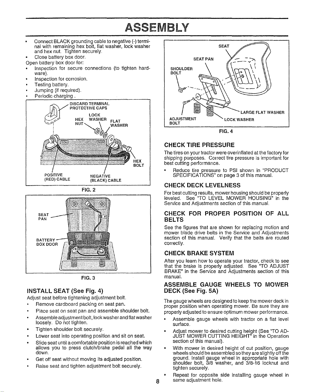
• First connect RED battery cable to positive (+) terminal
with hex bolt, flat washer, lock washer and hex nut as
shown. Tighten securely.
i ii nil ,,, n iinlllll Ill,I i illlll,lllllmlll I
ASSEMBLY
n illllllll, i I n i ii illlllll unlnl,lU I
* Connect BLACK grounding cable to negative (-) termi-
nal with rernaining hex bolt, flat washer, lock washer
and hex nuL Tighten securely.,
= Close battery box doon
Open battery box door for:
. Inspection for secure connections (to tighten hard-
ware),
• Inspection for corrosion_
• Testing battery,
• Jumping (if required),
Periodic charging.
POSITIVE NEGATIVE
(RED) CABLE (BLACK) CABLE
FIG. 2
SEAT
PAN
BATTEF
BOX DOOR
FIG. 3
INSTALL SEAT (See Fig. 4)
Adjust seat before tightening adjustment bolt.
° Remove cardboard packing on seat pan.
• Place seat on seat pan and assemble shoulder bolt.
• Assemble adjustment bolt, Iockwasher and flat washer
loosely, Do not tighten.
o Tighten shoulder bolt securely.
. Lower seat into operating position and sit on seat.
. Slide seat until a comfo rtabte position is reached which
allows you to press clutch/brake pedal all the way
down,,
• Get off seat without moving its adjusted positionv
• Raise seat and tighten adjustment bolt securely.
,i ii i lUUl i i ill lunnlllllllll,i
EAT,A. III
BOLT
FIG. 4
8
CHECK TIRE PRESSURE
The tires on your tractor were ovefinflated at the factory for
shipping purposes. Correct tire pressure is important for
best cutting performance,
. Reduce tire pressure to PSI shown in "PRODUCT
SPECIFICATIONS" on page 3 of this manual
CHECK DECK LEVELNESS
For best cutting results, mower housing should be properly
leveled. See "TO LEVEL MOWER HOUSING" in the
Service and Adjustments section of this manua!,
CHECK FOR PROPER POSITION OF ALL
BELTS
See the figures that are shown for replacing motion and
mower blade drive belts in the Service and Adjustments
section of this manual,. Verify that the belts are routed
correctly_
CHECK BRAKE SYSTEM
After you learn how to operate your tractor', check to see
that the brake is properly adjusted_ See "TO ADJUST
BRAKE" in the Service and Adjustments section of this
manual
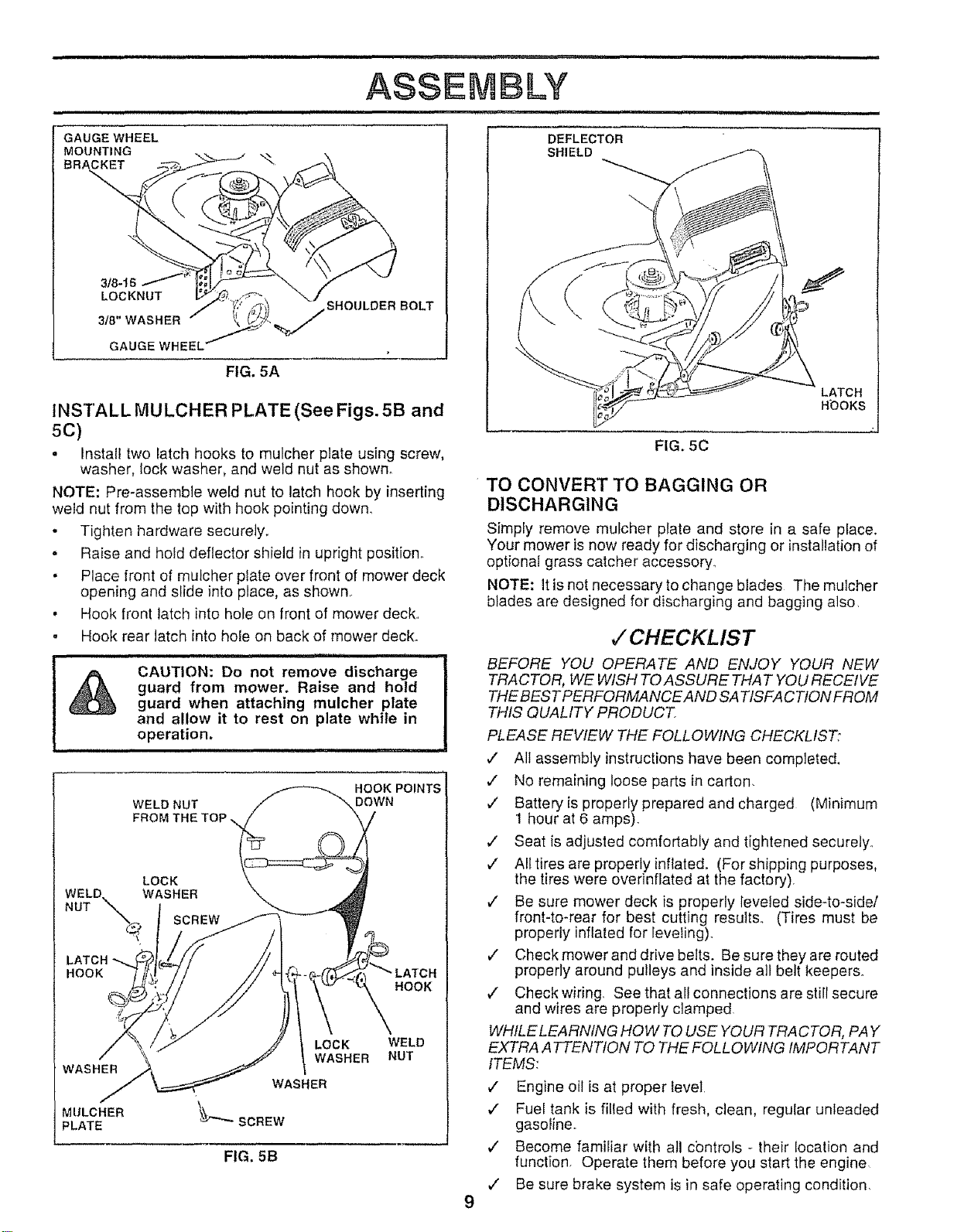
ASSEMBLE GAUGE WHEELS TO MOWER
DECK (See Fig. 5A)
The gauge wheels are designed to keep the mower deck in
proper position when operating mower'. Be sure they are
properly adjusted to ensure optimum mower performance.
. Assemble gauge wheels with tractor on a flat level
surface.
• Adjust mower to desired cutting height (See "TO AD-
" " O tO
JUST MOWER CUTTING HEIGHT In the pelat' n
section of this manual).
. With mower in desired height of cut position, gauge
wheels should be assembled so they are slightly off the
groun& Install gauge wheel in appropriate hole with
shoulder bolt, 3/8 washer, and 3/8-16 locknut and
tighten securely,
o Repeat for opposite side installing gauge wheel in
same adjustment holeo
ASSEMBLY
1,,,,,,,1,,,,=u= 1,11 = = m,== = . ,,,,,,1,,,1
GAUGE WHEEL
MOUNTING
BRACKET
318-16
LOCKNUT
318" WASHER
GAUGE WHE
FIG. 5A
SHOULDER BOLT
INSTALL MULCHER PLATE (See Figs. 5B and
5C)
° Install two latch hooks to mulcher plate using screw,
washer, lock washer, and weld nut as shown°
NOTE: Pre-assemble weld nut to latch hook by inserting
weld nut from the top with hook pointing down,
° Tighten hardware securely.
. Raise and hold deflector shield in upright position°
• Place front of mulcher plate over front of mower deck
opening and slide into place, as shown.
, Hook front latch into hole on front of mower deck..
o Hook rear latch into hole on back of mower deck.
=m=M,rml,m,=,=, = .................
CAUTION: Do not remove discharge ]
guard from mower. Raise and hold
guard when attaching mulcher plate
and allow it to rest on plate while in
operation.
,,,,=,,,,,,H= H== H
HOOK POINTS
WELD NUT DOWN
LOCK
WELD WASHER
NUT "_,
LATCH *-.
HOOK
HOOK
WASHER
MULCHER
=LATE
LOCK
WASHER
WASHER
SCREW
WELD
NUT
FIG. 5B
DEFLECTOR
SHIELD
LATCH
HbOKs
FIG. 5C
TO CONVERT TO BAGGING OR
DISCHARGING
Simply remove mufcher plate and store in a safe place.
Your mower is now ready for discharging or installation of
optional grass catcher accessory.
NOTE: It is not necessary to change blades The mulcher
blades are designed for discharging and bagging also,
CHECKLIST
BEFORE YOU OPERATE AND ENJOY YOUR NEW
TRACTOR, WE WISH TOASSURE THAT YOU RECEIVE
THE BEST PERFORMANCE AND SA TISFACTION FROM
THIS QUALITY PRODUCT
PLEASE REVIEW THE FOLLOWING CHECKLIST:
,/ All assembly instructionshave been completed.
v" No remaining loose parts in carton,
,/ Batteryis properly prepared and charged (Minimum
1 hour at 6 amps).
,/ Seat is adjusted comfortably and tightened securely,.
,/ Alltires are properly inflated. (For shipping purposes,
the tires were overinflated at the factory),
,/ Be sure mower deck is properly leveled side-to-side/
front-to-rear for best cutting results.. (Tires must be
properly inflated for leveling)°
¢" Check mower and drive belts. Be sure they are routed
properly around pulleys and inside all belt keepers.
,/ Check wiring. See that al! connections are still secure
and wires are properly clamped
WHILE LEARNING HOW TO USE YOUR TRACTOR, PAY
EXTRA ATTENTION TO THE FOLLOWING IMPORTANT
ITEMS:
v" Engine oil is at proper level.
,/ Fuel tank is filled with fresh, clean, regular unleaded
gasoline.
¢' Become familiar with all cbntrols - their location and
function. Operate them before you start the engine.
,/ Be sure brake system is in safe operating condition.
OPERAT O
,,, i Hun,,, Hn,,,, i n lllnnH,,,, l l,l, i ii, .................. ,,,,,,, ,,, , .........
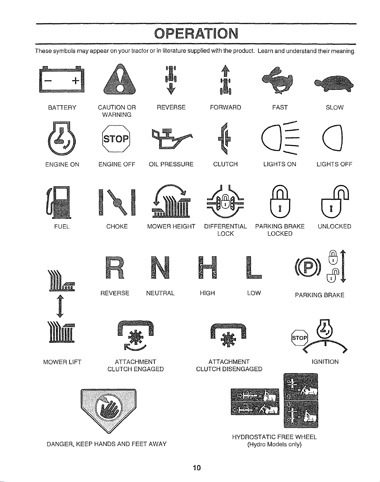
These symbols may appear on your' tractor or in literature supplied with the product. Learn and understand their' meaning,
BATTERY CAUTION OR REVERSE FORWARD FAST SLOW
WARNING
ENGINE ON ENGINE OFF OtL PRESSURE CLUTCH LIGHTS ON LIGHTS OFF
FUEL
\
CHOKE MOWER HEIGHT DIFFERENTIAL PARKING BRAKE UNLOCKED
LOCK LOCKED
MOWER LIFT
R
REVERSE NEUTRAL
ATTACHMENT
CLUTCH ENGAGED
L
HIGH LOW
ATTACHMENT
CLUTCH DISENGAGED
PARKING BRAKE
IGNITION
DANGER, KEEP HANDS AND FEET AWAY
HYDROSTATIC FREE WHEEL
(Hydro Models only)
10
OPERATION
,ull i i i mimH,,,, H,i i, i i , i, H,,i,,,ll i ,,u ul, i
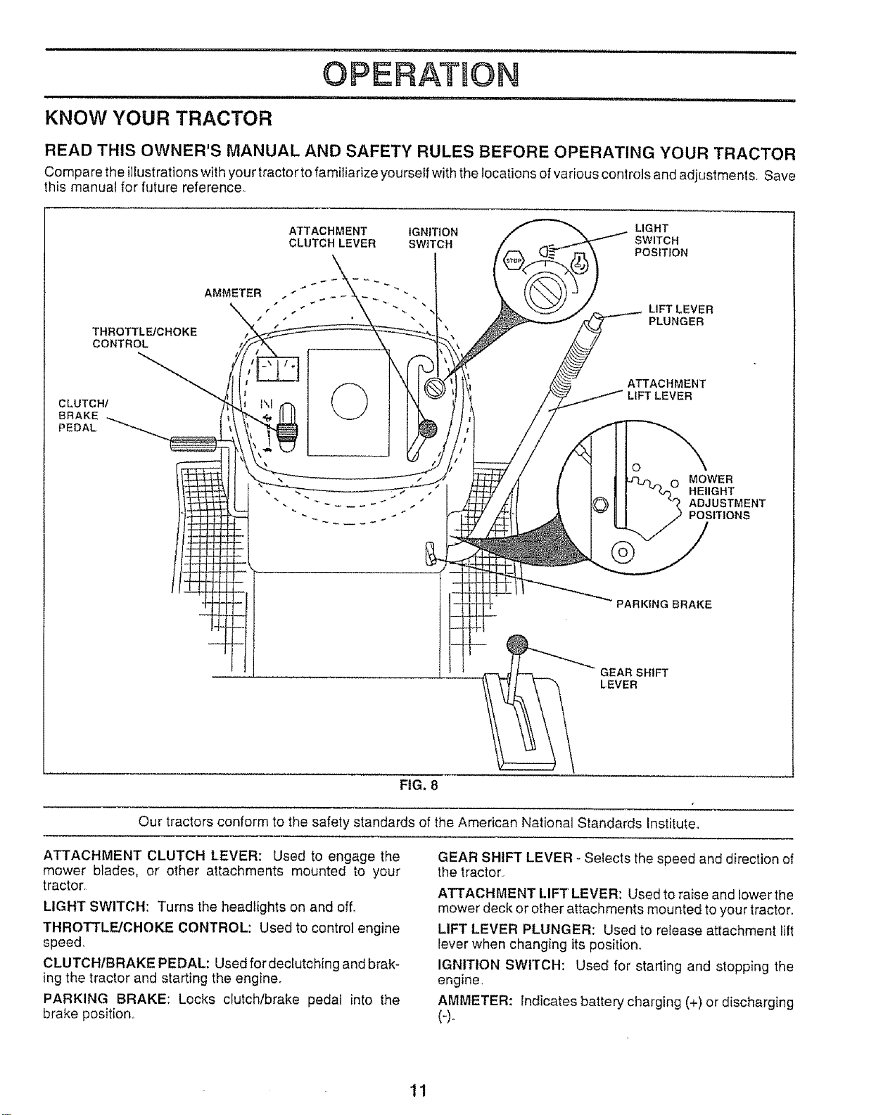
KNOW YOUR TRACTOR
READ THiS OWNER'S MANUAL AND SAFETY RULES BEFORE OPERATING YOUR TRACTOR
Compare the illustrations with your tractor to familiarize yourseIf with the locations of various controls and adjustments, Save
this manual for future reference,
THROTTLE/CHOKE
CONTROL
ATTACHMENT
CLUTCH LEVER
AMMETER ,. _ .__ _
IGN|TION LIGHT
SWITCH SWITCH
POSITION
LIFT LEVER
PLUNGER
CLUTCH/
BRAKE
PEDAL
©
ATTACHMENT
LIFT LEVER
O
MOWER
HEIIGHT
ADJUSTMENT
POSITIONS
PARKING BRAKE
GEAR SHIFT
LEVER
FIG. 8
Our tractors conform to the safety standards of the American National Standards Institute.
ATTACHMENT CLUTCH LEVER: Used to engage the
mower blades, or other attachments mounted to your
tractor,
LIGHT SWITCH: Turns the headlights on and off°
THROTTLE/CHOKE CONTROL: Used to control engine
speed,
CLUTCH/BRAKE PEDAL: Used for declutching and brak-
ing the tractor and starting the engine°
PARKING BRAKE: Locks clutch/brake pedal into the
brake position,
GEAR SHIFT LEVER - Selects the speed and direction of
the tractor
ATTACHMENT LIFT LEVER: Used to raise and lower the
mower deck or other attachments mounted to your tractor°
LIFT LEVER PLUNGER: Used to release attachment lift
lever when changing its position°
IGNITION SWlI"CH: Used for starting and stopping the
engine,
AMMETER: indicates battery charging (+) or discharging
{-).
11
OPERATION
i i iil,,i, IN,IIIIII ,,
i ,ira i i ii,lll,l_ln .................................. ii iiiii¸ ,,,,,,,,,,,,,,,,,,,,, ii
!
The operation of any tractor can result in foreign objects thrown into the eyes, which can I
result in severe eye damage, Always wear safety glasses or eye shields while operating you r
!
tractor or perfor ruing any adjustments or repairs, We recommend a wide vision safety mask
over the spectacles or standard safety glasses,
i, i1,1, i,m ........................ 1,'lr ,i i1,1ii i, ii i,, i! iii, ii, iiii
HOW TO USE YOUR TRACTOR
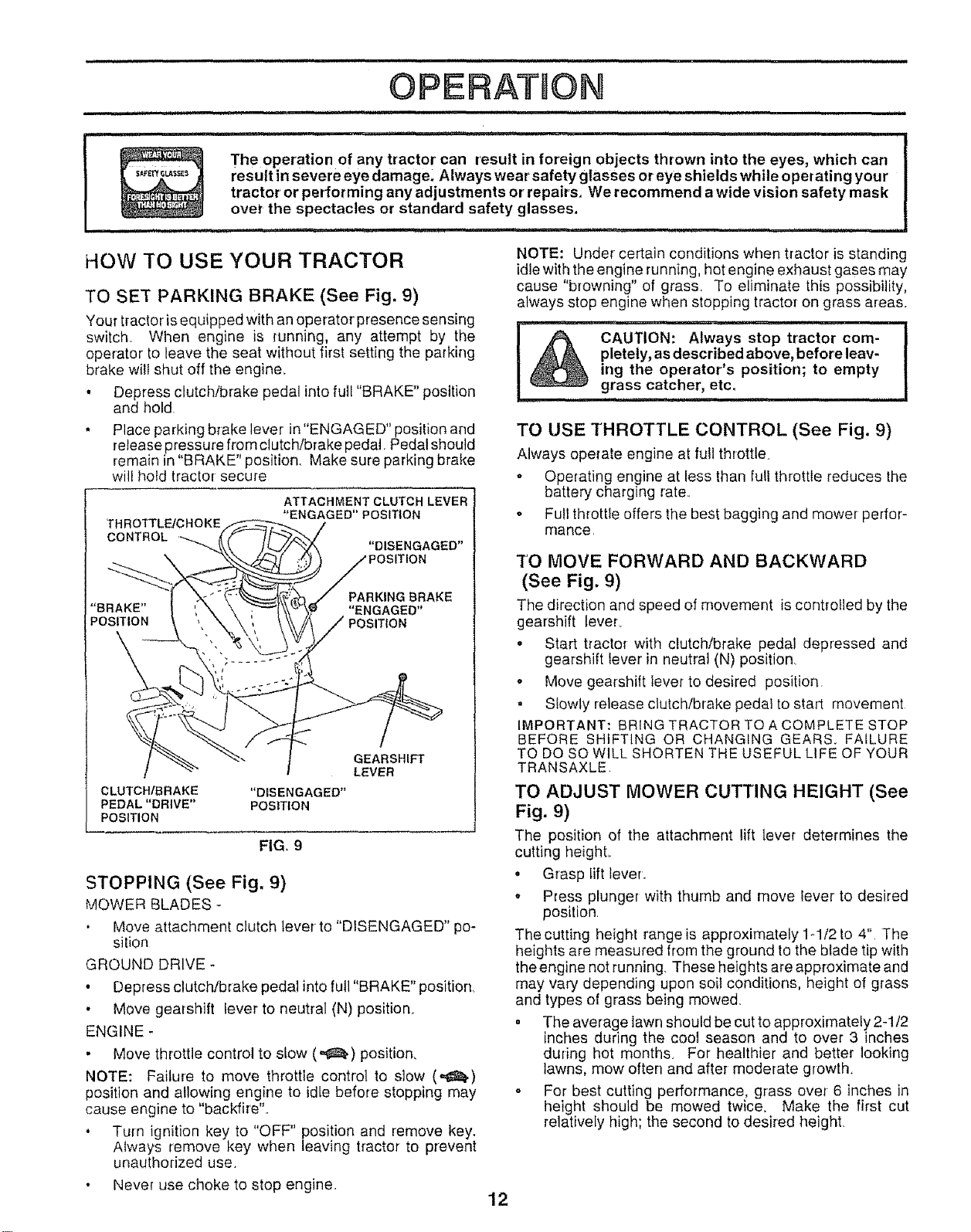
TO SET PARKING BRAKE (See Fig. 9)
Your tractor isequipped with an operator presence sensing
switch When engine is running, any attempt by the
operator to leave the seat without first setting the parking
brake w[l{ shut off the engine.
• Depress clutch/brake pedal into full "BRAKE" position
and hold
• Place parking brake lever in "ENGAGED" position and
release pressure from clutch/brake pedal. Pedal should
remain in BRAKE position. Make sure parking brake
will hold tractor secure
THROTTLEICHOKE
CONTROL "---.._
ATTACHMENT CLUTCH LEVER
"ENGAGED'POSIT|ON
PARKING BRAKE
"BRAKE" "ENGAGED"
POSITION POSITION
\
CLUTCHIBRAKE "DISENGAGED"
PEDAL "DRIVE" POSITION
POSITION
GEARSHIFT
LEVER
FIG, 9
STOPPING (See Fig. 9)
MOWER BLADES -
Move attachment clutch lever to "DISENGAGED" po-
silion
GROUND DRIVE -
• Depress ctutchtbrake pedal into full "BRAKE" position
• Move gearshift lever to neutral (N) position.
ENGINE -
. Move throttle control to stow (,,,_.) position,
NOTE: Failure to move throttle control to slow (,,_)
position and allowing engine to idle before stopping may
cause engine to "backfire"..
* Turn ignition key to "OFF" position and remove key.
Always remove key when leaving tractor to prevent
unauthorized use.
Never use choke to stop engine.
NOTE: Under certain conditions when t_actor is standing
idle with the engine running, hot engine exhaust gases may
cause "browning" of grass. To eliminate this possibility,
always stop engine when stopping tractor on grass areas.
IIH ,11 'IN'Ill,I,
CAUTION: Always stop tractor com-
pletely, as described above, before leav-
ing the operator's position; to empty
grass catcher, etc.
i i,im, i i ii mll
TO USE THROTTLE CONTROL (See Fig. 9)
Always operate engine at full throttle.
= Operating engine at less than full throttle reduces the
battery charging rate.
o Full throttle offers the best bagging and mower perlor-
mance
TO MOVE FORWARD AND BACKWARD
(See Fig. 9)
The direction and speed of movement is controlled by the
gearshi{t lever°
. Start t_actoi with clutch/brake pedal depressed and
gearshift lever' in neutral (N) position
- Move gearshift lever to desired position
- Slowly release clutch/brake pedal to start movement
IMPORTANT: BRING TRACTOR TO A COMPLETE STOP
BEFORE SHIFTING OR CHANGING GEARS. FAILURE
TO DQ SO WILL SHORTEN THE USEFUL LIFE OF YOUR
TRANSAXLE.
TO ADJUST MOWER CUTTING HEIGHT (See
Fig. 9)
The position of the attachment lift leve_ determines the
cutting height.
• Grasp lift lever..
• Press plunger with thumb and move lever to desired
position
The cutting height range is approximately 1-1/2 to 4" The
heights are measured from the ground to the blade tip with
the engine not running. These heights are approximate and
may vary depending upon soil conditions, height of grass
and types of grass being mowed.
. The average lawn should be cut to approximately 2-1/2
inches during the cool season and to over 3 inches
during hot months. For healthier and better looking
lawns, mow often and after moderate growth.
o For best cutting performance, grass over 6 inches in
height should be mowed twice. Make the first cut
relatively high; the second to desired height.
12
OPERAT!ON
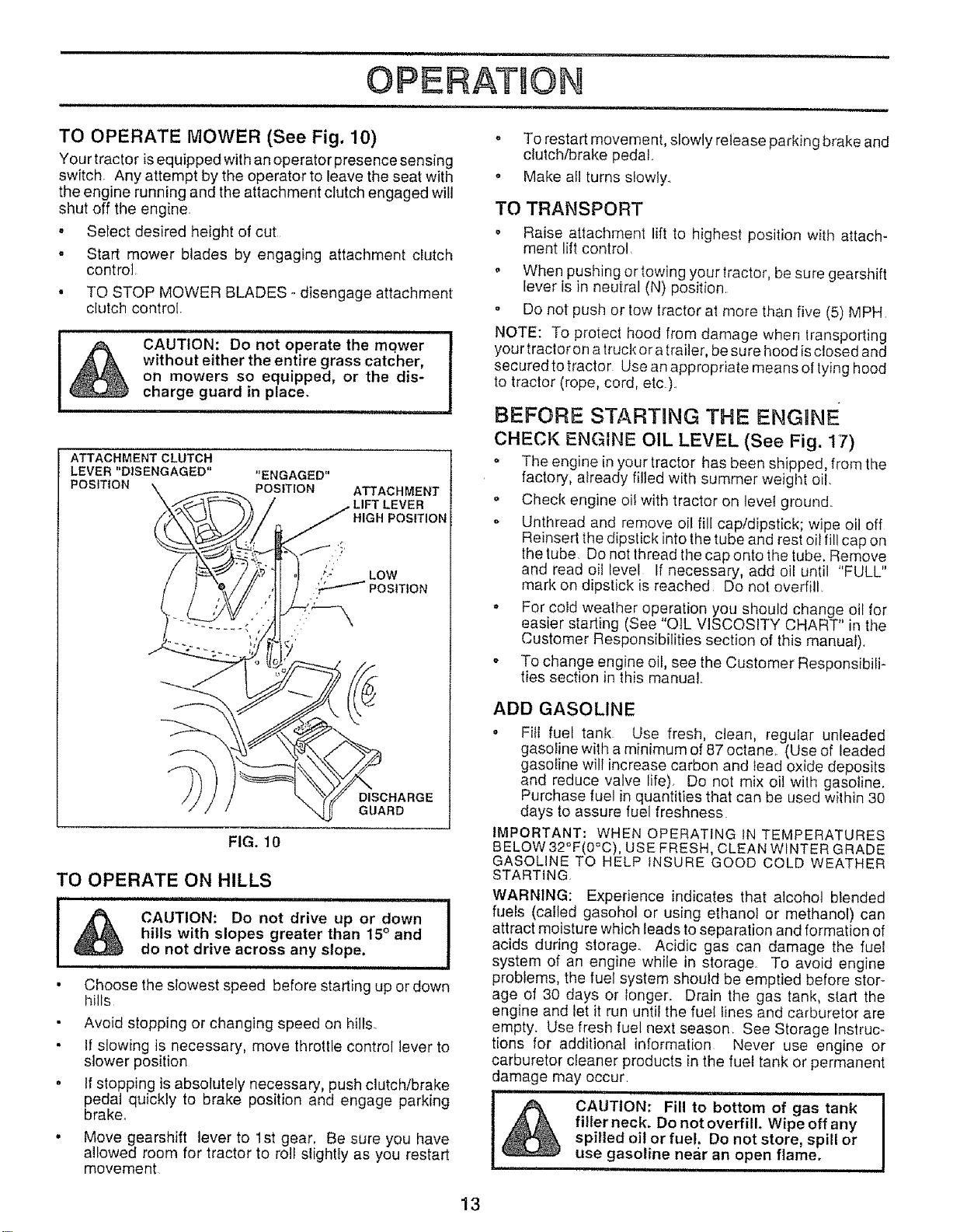
TO OPERATE MOWER (See Fig. 10)
Your tractor is equipped with an operator presence sensing
switch Any attempt by the operator to leave the seat with
the engine running and the attachment clutch engaged will
shut off the engine
, Select desired height of cut
• Start mower blades by engaging attachment clutch
control,
• TO STOP MOWER BLADES odisengage attachment
clutch control,
CAUTION: Do not operate the mqwer
without either the entire grass catcher,
on mowers so equipped, or the dis-
charge guard in place.
i i .....................
ATTACHMENT CLUTCH
LEVER "DISENGAGED"
POSITION
"ENGAGED"
POSITION
ATTACHMENT
• LIFT LEVER
HIGH POSITION
;" LOW
POSITION
FIG. 10
DISCHARGE
GUARD
TO OPERATE ON HILLS
..............I
CAUTION: Do not drive up or down
hills with slopes greater than 15° and
do not drive across any slope,
u ii
Choose the slowest speed before starting up or down
hills
o
Avoid stopping or changing speed on hills.
If slowing is necessary, move throttle control lever to
slower position
If stopping is absolutely necessary, push clutch/brake
pedal quickly to brake position and engage parking
brake.
° Move gearshift lever to 1st gear. Be sure you have
allowed room for tractor to roll slightry as you restart
movement
o To restart movement, slowly release parking brake and
clutch/brake pedal..
o Make all turns slowly.
TO TRANSPORT
o Raise attachment lift to highest position with attach-
ment lift control.
,' When pushing or towing your tractor, be sure gearshift
lever is in neutral (N) position.
,, Do not push or tow tractor at more than five (5) MPH
NOTE: To protect hood from damage when lransporting
your tractor on a truckor a trailer,be sure hood isclosed and
secured to tractor Use an appropriate means of tyinghood
to tractor (rope, cord, etc ).
BEFORE STARTING THE ENGHNE
CHECK ENGINE OIL LEVEL (See Fig. 17)
o The engine in your tractor has been shipped, from the
factory, already filled with summer weight oil.
,, Check engine oil with tractor on level ground.
', Unthread and remove oil fill cap/dipstick; wipe oil off
Reinsed the dipstick into the tube and rest oil fill cap on
the tube. Do not thread the cap onto the tube+Remove
and read oil level If necessary, add oil until "FULL"
mark on dipstick is reached Do not overfill.
o For cold weather operation you should change oil for
easier starting (See "OIL VISCOSITY CHART" in the
Customer Responsibilities section of this manual).
o To change engine oil, see the Customer Responsibili-
ties section in this manual+
ADD GASOLINE
° Fill fuel tank Use fresh, clean, regular unleaded
gasoline with a minimum of 87 octane+ (Use of leaded
gasoline will increase carbon and lead oxide deposits
and reduce valve life). Do not mix oil wilt] gasoline.
Purchase fuel in quantities that can be used within 30
days to assure fuel freshness
IMPORTANT: WHEN OPERAT1NGtN TEMPERATURES
BELOW 32°F(0°C), USE FRESH, CLEAN WINTER GRADE
GASOLINE TO HELP INSURE GOOD COLD WEATHER
STARTING
WARNING: Experience indicates that alcohol blended
fuels (called gasohot or using ethanol or methanol) can
attract moisture which leads to separation and formation of
acids during storage.. Acidic gas can damage the fuel
system of an engine while in storage. To avoid engine
problems, the fuel system should be emptied before stor+
age of 30 days or Ionger. Drain the gas tank, start the
engine and let it run until the fuel lines and carburetor are
empty. Use fresh fuel next season See Storage Instruc-
tions for additional information Never use engine or
carburetor cleaner products in the fuel tank or permanent
damage may occur
,,,,pll,m,i i H,i IHH II
CAUTION: Fill to bottom of gas tank
fi!ler neck. Do not overfill Wipe off any
spilled oil or fuel, Do not store, spill or
use gasoline near an open flame.
iiiii iiHu ,
13
, u, , ,I_Ju.l,,I I I III ,,,I,,¸ I1,11,,,¸ I1,,H ' UU,U ,,,UI,I I1,1,
OPERATION
................ _..... , ,,u ,,, u
TO START ENGINE (See Fig, 9)
When starting the engine for the first time or if the engine
has run out of fuel, it wilt take extra cranking time to move
fuel from the tank to the engine.
• Sit on seat in operating position, depress clutch/brake
pedal and set parking brake.
• Place gear shift lever in neutral (N) position
• Move attachment clutch to "DISENGAGED" position,
• Move throttle control to choke (N) position
Note: Before starting, read the warm and cold starting
procedures below
. tnsert keyinto ignition and turn key clockwise to"START"
position and release key as soon as engine starts, Do
not run starter continuously for more than fifteen sec-
onds per minute If the engine does not start after
several attempts, move throttle control to fast (,,_)
position, wait afew minutes and try again,. Ifengine still
does not start, move the throttle control back to the
choke (N) position and retry_
WARM WEATHER STARTING (50° F and above)
- When engine starts, move the throttle control to the fast
(ze_)position.
The attachments and ground drive can nowbe used. ]f
the engine does not accept the load, restart the engine
and allow it to warm up for one minute using the choke
as described above.
COLD WEATHER STARTING ( 50° F and below)
• When engine starts, allow engine to run with the throttle
control in the choke (\!) position until the engine runs
roughly, then move thrott e contro to fast (,_) posit on..
This may require an engine warm-up period from
several seconds to several minutes, depending on the
temperature
• The attachments can also be used during the engine
warm-up period.
NOTE: tf at a high altitude (above 3000 feet) or in cold
[emperatures (below 32 F) the carburetor fuel mixture may
need Io be adjusted for best engine performance. See"TO
ADJUST CARBURETOR" in the Service and Adjustments
section of this manual.
MOWING TIPS
• Mower should be properly leveled for best mowing
performance See"TO LEVEL MOWER HOUSING" in
the Service and Adjustments section of this manual
• The left hand side of mower shoutd be used for trim-
ming
• Drive so that clippings are discharged onto the area
that has been cut. Have the cut area to the right of the
machine This will result in a more even distribution of
clippings and more uniform cutting.
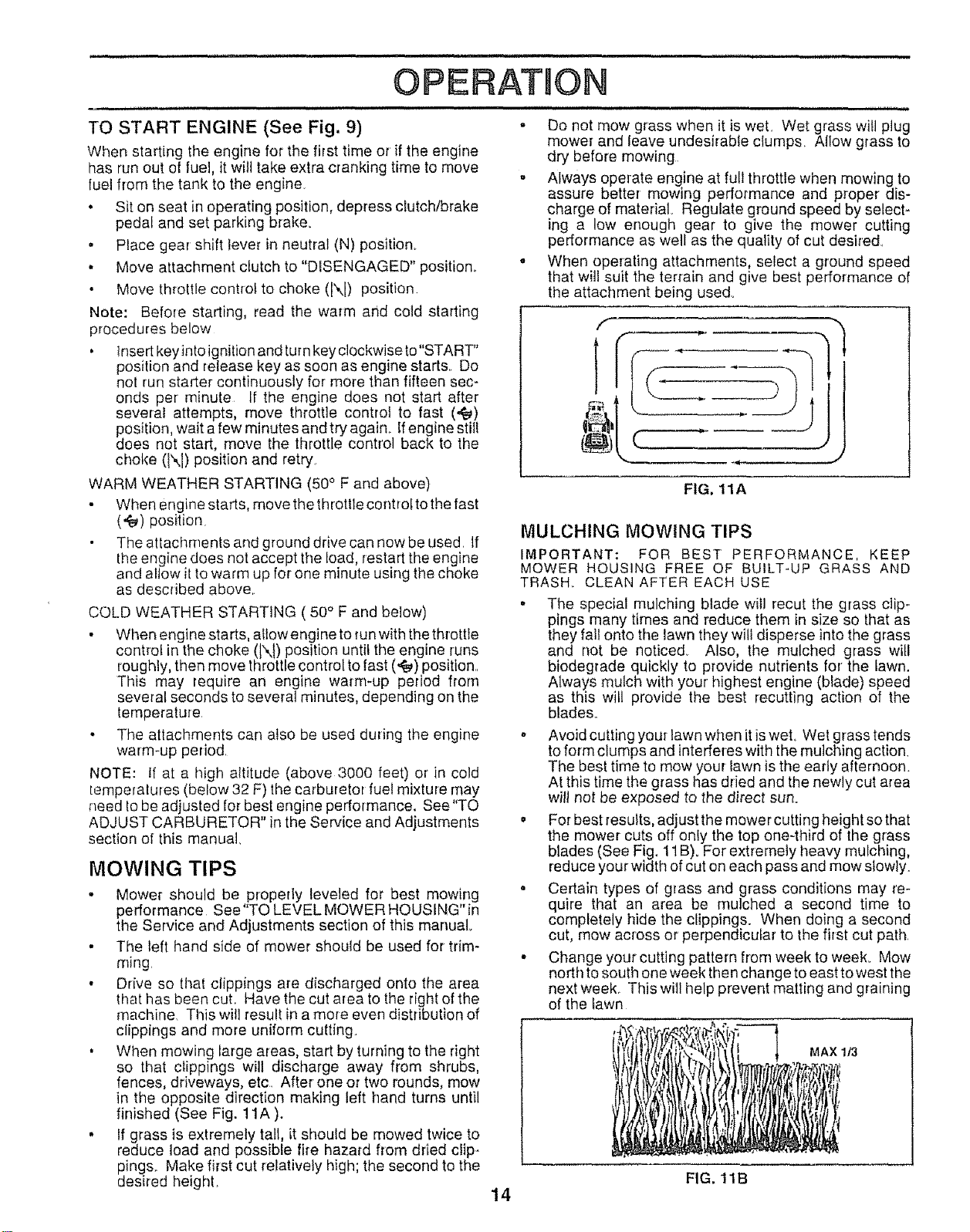
• When mowing large areas, start by turning to the right
so that clippings will discharge away from shrubs,
fences, driveways, etc. After one or two rounds, mow
in the opposite direction making left hand turns until
finished (See Fig. ! 1A ).
• If grass is extremely tall, it should be mowed twice to
reduce load and possible fire hazard from dried clip-
pings. Make first cut relatively high; the second to the
desired height,
i,,,11,11,,,, , ii , , u ,ulJ ...................
,, Do not mow grass when it is wet. Wet grass will plug
mower and leave undesirable clumps, Allow grass to
dry before mowing.
° Always operate engine at full throttle when mowing to
assure better mowing performance and proper dis-
charge of material,. Regulate ground speed by select-
ing a low enough gear to give the mower cutting
performance as well as the quality of cut desired
° When operating attachments, select a ground speed
that will suit the terrain and give best performance of
the attachment being used°
FIG. 11A
MULCHING MOWING TIPS
IMPORTANT: FOR BEST PERFORMANCE, KEEP
MOWER HOUSING FREE OF BUILT-UP GRASS AND
TRASH. CLEAN AFTER EACH USE
• The special mulching blade will recur the grass clip-
pings many times and reduce them in size so that as
they falt onto the lawn they will disperse into the grass
and not be noticed. Also, the mulched grass will
biodegrade quickly to provide nutrients for the lawn.
Always mulch with your highest engine (blade) speed
as this will provide the best recutting action of the
blades.
. Avoid cutting your lawn when it is wet. Wet grass tends
to form clumps and interferes with the mulching action.
The best time to mow your lawn is the early afternoon.
At this time the grass has dried and the newly cut area
will not be exposed to the direct sun°
* For best results, adjust the mower cutting height so that
the mower cuts off only the top one-third of the grass
blades (See Fig. 11 B). For extremely heavy mulching,
reduce your width of cut on each pass and mow slowly.
o Certain types of grass and grass conditions may re-
quire that an area be mulched a second time to
completely hide the clippings. When doing a second
cut, mow across or perpendicular to the first cut path.
. Change your cutting pattern from week to week. Mow
north to south one week then change to east to west the
next week.. This will help prevent matting and graining
of the fawn
MAX 1/3
FIG. 11B
14
CUSTOMER RESPONSIBULR'UES
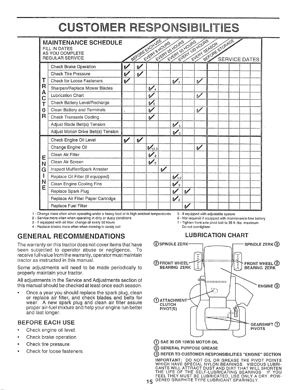
MAINTENANCE SCHEDULE /__ ._o__o__
FILL IN DATES /__'_'_/_._
ASYouCOMPLETE
REGULARSERV!OE / Y' .YSERV'CE DA'rEs
Check Brake Operation $/ e/
Check Tire Pressure _#',. V _'
T Check for Loose Fasteners 6/ 6f 7
a Sharpen/Replace Mower Blades ......................
u b 3 .......
Lubrication Chart _'
T Check Batlery LevellRecharge
0 Clean Battery and Terminals ....6./ .............. _'
R Check Transaxle Cooling 6,,4"
Adjust Blade Belt(s) Tension ,6/5
Adjust Motion Drive Bell(s) Tension ........................... 6#45
Check Engine Oil Leve!
Change Engine Oil
Clean Air Filler
E
N Clean Air Screen
e Inspect Muffler/Spark Arrester
I Replace Oil Filter (If equipped)
N Clean Engine Cooling Fins ....
Replace Spark Plug
Replace Air Filter Paper Ca4ridge
Replace Fuel Filter
d i3 v" ..................
J v'
1 - Change more ollen when operating under a heavy load or in high ambient temperatures
2 - Service more of Ion when ope_alfng in dtrly or dusty conditions
3 - I1equipped wilh oil filler, change oil every 50 l_ours
4 - Replace blades more often when mowing in sandy soll
5 - If equipped wilh adiuslabie system
6 - Not requ[re_! if equipped wilh mainlenance-iree ballery
7 - Tighten t[onl axle pivot bolt to 35 ft -Ibs maximum
Do not overlighlen
GENERAL RECOMMENDATIONS
The warranty on this tractor does not cover items that have
been subjected to operator abuse or negligence° To
receive full value from the warranty, operator must maintain
tractor as instructed in this manual
Some adjustments will need to be made periodically to
properly maintain your tractor.
All adjustments in the Service and Adjustments section of
this manual should be checked at least once each season.
Once a year you should replace the spark plug, clean
or replace air filter, and check blades and belts for
wear. A new spark plug and clean air filter assure
proper air-fuel mixture and help your engine run better
and last longer.
LUBRICATION CHART
(_ FRONT WHEE
BEARING ZERK
" FRONT WHEEL (_)
BEARING ZERK
CLUTCH
PIVOT(S)
BEFORE EACH USE
• Check engine oil level.
" Check brake operation,
', Check tire pressure
,, Check for loose fasteners,
(9
PIVOTS
(9 SAE 30 OR 10W30 MOTOR OIL
(_) GENERAL PURPOSE GREASE
(_) REFER TO CUSTOMER RESPONSIBILITIES "ENGtNE" SECTION
IMPORTANT; DO NOT OIL OR GREASE THE PIVOT POINTS
WHICH HAVE SPECIAL NYLON BEARINGS VISCOUS LUBRI-
CANTS WILL ATTRACT DUST AND DIRT THAT WILL SHORTEN
THE LIFE OF THE SELF-LUBRICATING BEARINGS IF YOU
FEEL THEY MUST BE LUBRICATED, USE ONLY A DRY. POW-
!5 DERED GRAPHITE TYPE LUBRICANT SPARINGLY
TRACTOR
Always observe safety rules when performing any mainte-
nance.
BRAKE OPERATION
If tractor requires more than six (6) feet stopping distance
at high speed inhighest gear, then brake must be adjusted.
(See "TO ADJUST BRAKE" in the Service and Adjust-
ments section of this manual).
TIRES
Maintain proper air pressure in a!! tires (See "PROD-
UCT SPECIFICATIONS" on page 3 of this manual).
. Keep tires free of gasoline, oil, or insect controE chemF
cals which can harm rubber.
• Avoid stumps, stones, deep ruts, sharp objects and
other hazards that may cause tire damage,
NOTE: To seal tire punctures and prevent flat tires due to
slow leaks, tire sealant may be purchased from yourtocal
parts dealer. Tire sealant also prevents tire dry rot and
corrosion
BLADE CARE
For best results mower blades must be kept sharp Re-
place bent or damaged blades.
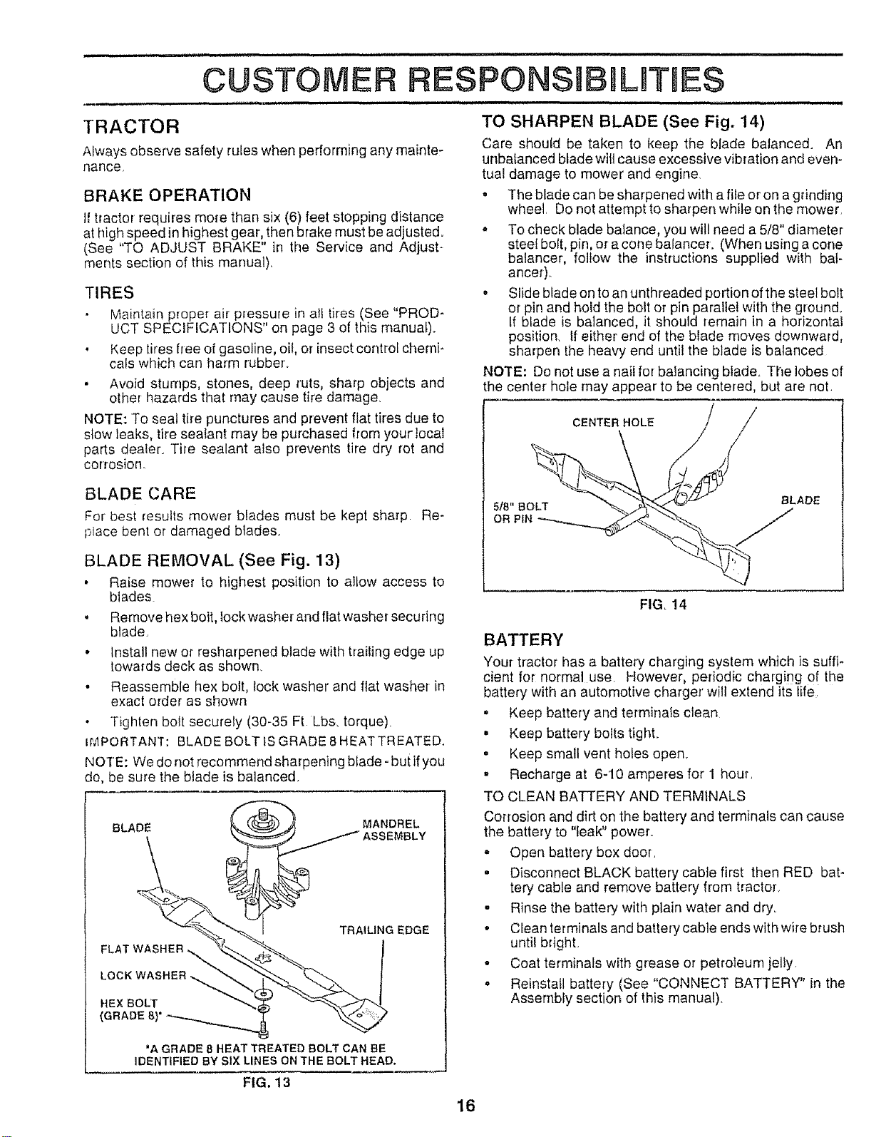
BLADE REMOVAL (See Fig. 13)
• Raise mower to highest position to allow access to
blades
o Remove hex bolt, lock washer and flat washer securing
blade.
• Install new or resharpened blade with trailing edge up
towards deck as shown.
• Reassemble hex bolt, lock washer and flat washer in
exact order as shown
Tighten bolt securely (30-35 Ft Lbs, torque)
H',4PORTANT: BLADE BOLT IS GRADE 8 HEATTREATED.
NOTE: We do not recommend sharpening blade -but ifyou
do, be sure the blade is balanced.
BLADE
MANDREL
TRAILING EDGE
FLAT WASHER !
LOC
HEXBOLT
(GRADE
'AGRADEaHEATTREATEDBOLTCAN BE
IDENTIFIED BYSIXLINESONTHEBOLTHEAD.
TO SHARPEN BLADE (See Fig. 14)
Care shoutd be taken to keep the blade balanced. An
unbalanced blade wilt cause excessive vibration and even-
tual damage to mower and engine.
o The blade can be sharpened with a file or on a grinding
wheel Do not attempt to sharpen while on the mower
o To check blade batance, you will need a 5/8" diameter
steel bolt, pin, or a cone balancer. (When using a cone
balancer, follow the instructions supplied with bat-
ancer)_
" Slide blade on to an unthreaded portion ofthe steel bolt
or pin and hold the bolt or pin parallel with the ground.
If blade is balanced, it should remain in a horizontal
position. If either end of the blade moves downward,
sharpen the heavy end until the blade is balanced
NOTE: Do not use a nail for balancing blade_ The lobes of
the center hole may appear to be centered, but are not.
CENTER HOLE
5ta"BOLT BLADE
OR PIN j
FIG. 14
BATTERY
Your tractor has a battery charging system which is suffF
cient for normal use. However, periodic charging of the
battery with an automotive charger will extend its life
. Keep battery and terminals clean
. Keep battery bolts tight
o Keep small vent holes open.
o Recharge at 6-10 amperes for 1 hour,
TO CLEAN BATTERY AND TERMINALS
Corrosion and dirt on the battery and terminals can cause
the battery to "leak" power,.
o Open battery box door,
• Disconnect BLACK battery cable first then RED bat-
tery cable and remove battery from tractor,
° Rinse the battery with plain water and dry.
° Clean terminals and battery cable ends with wire brush
until bright,
o Coat terminals with grease or petroleum jelly
o Reinstall battery (See "CONNECT BATTERY" in the
Assembly section of this manual).
FIG. 13
16
i iiiiii
CUSTOMER
V-BELTS
Check V-belts for deterioration and wear after 100 hours of
operation and replace if necessary, The belts are not
adjustable° Replace belts if they begin to slip from wear°
TRANSAXLE COOLING
Keep transaxle free from build-up of dirt and chaff which
can restrict cooling°
ENGINE
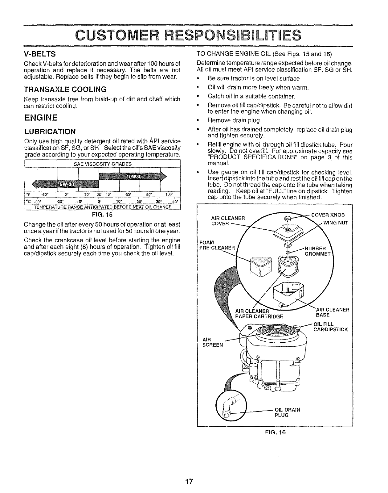
LUBRICATION
Only use high quality detergent oil rated with API service
c_assification SF, SG, or SH. Select the oil's SAE viscosity
grade according to your expected operating temperature°
SAE VISCOSITY GRADES
t ! J
I ....
_F "204 09 30 ° 32" 40 = 60 _ B0_'' _00 _
°C .30= -20° -10" 0_ 1'0_ 20° ,,, 30" .......40°
TEMPERATURE RANGE ANTICIPATED BEFORE NEXT OIL CHANGE
FIG. 15
i ,i, i ..................................i , i i_,,,, IIHIIIII , ii
RESPONS LRTIES
H,_I_L i, rill ,i , ,I,,H
TO CHANGE ENGINE OiL (See Figs. 15 and 16)
Determine temperature range expected before oil change_
All oil must meet API service classification SF, SG or SHo
o Be sure tractor is on level surface
• Oil wi!l drain more freely when warm,
o Catch oil in a suitable container_
o Remove oil fill cap/dipstick_ Be careful not to allow dirt
to enter the engine when changing oil.
o Remove drain plug
- After oil has drained completely, replace oil drain plug
and tighten secure{y.
= Refill engine with oil through oil fill dipstick tube. Pour
slowly. Do not overfill For approximate capacity see
"PRODUCT SPECIFICATIONS" on page 3 of this
manual
= Use gauge on oil fill cap/dipstick for checking level.
Insert dipstick into the tube and rest the oil fill cap on the
tube. Do not thread the cap onto the tube when taking
reading° Keep oil at"FULL" line on dipstick Tighten
cap onto the tube securely when finished,
Change the oil after every 50 hours of operation or at least
once a year if the tractor is not used for 50 hours inone year,,
Check the crankcase oil level before starting the engine
and after each eight (8) hours of operation, Tighten oil fill
cap/dipstick securely each time you check the oil level..
AIR CLEANER
COVER • WING NUT
FOAM
PRE-CLEANER
AIR
SCREEN
PAPER CARTRIDGE
AIR CLEANER
BASE
CAP/DIPSTICK
PLUG
FIG. 16
17
CLEAN AIR SCREEN (See Fig, 16)
Air screen must be kept free of dirt and chaff to prevent
engine damage from overheating., Clean with awire brush
or compressed air to remove dirt and stubborn dried gum
fibers_
AIR FILTER (See Fig. 16)
Your engine will not run properly using a dirty air filter,
Clean the foam pre-cleaner after' every 25 hours of opera-
tion or every season° Service paper cartridge every 100
hours of operation or every season, whichever occurs first.
Service air cleaner more often under dusty conditions°
* Remove knob and cover,
* Remove wing nut and air cleaner from base.
TO SERVICE PRE-CLEANER
• Slide foam pro-cleaner off cartridge.
. Wash it in liquid detergent and water°
. Squeeze it dry in a clean ciotho Allow itto dry.
• Saturate it in engine oil Wrap it in clean, absorbent
cloth and squeeze to remove excess oil,
TO SERVICE CARTRIDGE
, Replace a dirty, bent, or damaged cartridge.
NOTE: Donor washthe papercartridge or use pressurized
air, as this will damage the cartridge°
Reinstall the pro-cleaner (cleaned and oiled) over the
paper cartridge,
. Reassemble air cleaner, wing nut, cover and tighten
knob securely,
CLEAN AIR INTAKE!COOLING AREAS
To insure proper cooling, make sure the grass screen,
cooling fins, and other external surfaces of the engine are
kept clean at all times,
Every 100 hours of operation (more often under extremely
dusty, dirty conditions), remove the blower housing and
other cooling shrouds. Clean the cooling fins and external
surfaces as necessary. Make sure the cooling shrouds are
reinstalled_
NOTE: Operating the engine with a blocked grass screen,
dirty or plugged cooling fins, and/or cooling shrouds re-
moved will cause engine damage due to overheating,
MUFFLER
Inspect and replace corroded muffler and spark arrestor (if
equipped) as itcould create a fire hazard and/or damage.
SPARK PLUGS
Replace spark plugs at the beginning of each mowing
season or after every 100 hours of operation, whichever
occurs first, Spark plug type and gap setting are shown in
"PRODUCT SPECIFICATIONS" on page 3 of this manual.
18
i i
CUSTO RESPONSBBIL TUES
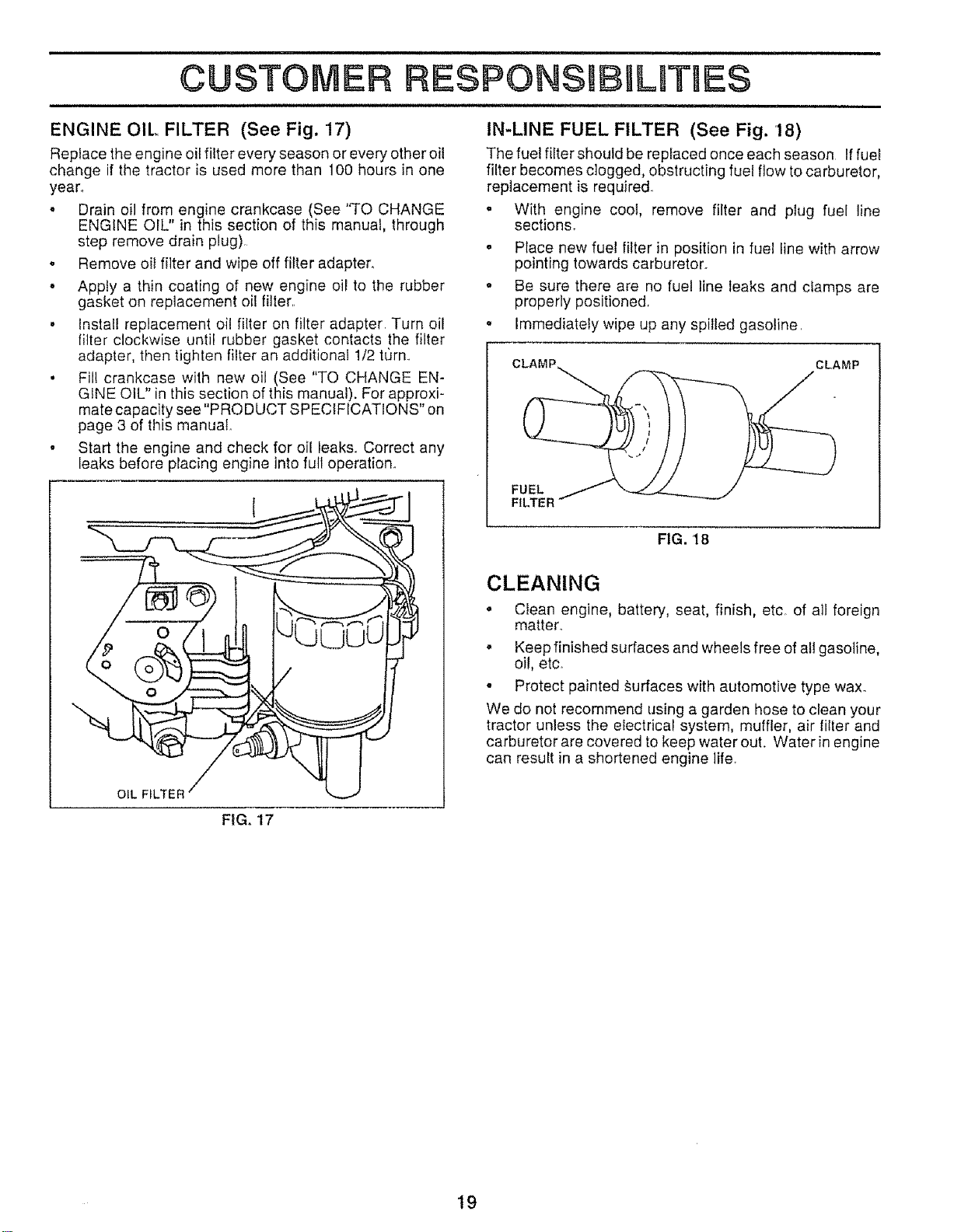
ENGINE OIL. FILTER (See Fig. 17)
Replace the engine oil filter every season or every other oil
change if the tractor is used more than 100 hours in one
yean
. Drain oil from engine crankcase (See "TO CHANGE
ENGINE OIL" in this section of this manual, through
step remove drain plug),
° Remove oil filter and wipe off filter adapter.
° Apply a thin coating of new engine oil to the rubber
gasket on replacement oil filler,
• Install replacement oil filter on filter adapter, Turn oil
filter clockwise until rubber gasket contacts the filter
adapter, then tighten filter an additional 1/2 t_rn.,
• Fil! crankcase with new oil (See "TO CHANGE EN-
GINE OIL" in this section of this manual). For approxi-
mate capacity see "PRODUCT SPECIFICATIONS" on
page 3 of this manual
• Start the engine and check for oil leaks, Correct any
leaks before placing engine into full operation,,
OIL FILTER
FIG. 17
IN-LINE FUEL FILTER (See Fig. 18)
The fue! filter should be replaced once each season If fuel
filter becomes clogged, obstructing fuel flow to carburetor,
replacement is required
o With engine cool, remove filter and plug fuel line
sections_
o Place new fue! filter in position in fuel line with arrow
pointing towards carburetor.
o Be sure there are no fuel line leaks and ctamps are
properly positioned
, Immediately wipe up any spilled gasoline.
CLAMP CLAMP
FUEL
FILTER
FIG. 18
CLEANING
• Clean engine, battery, seat, finish, etco of all foreign
matter..
• Keep finished surfaces and wheels free of all gasoline,
oil, etc.
o Protect painted surfaces with automotive type wax.
We do not recommend using a garden hose to clean your
tractor unless the electrical system, muffler, air filler and
carburetor are covered to keep water out. Water in engine
can result in a shortened engine life.
19
CAUTION: BEFORE PERFORMING ANY SERVICE OR ADJUSTMENTS:
:
o
0
Jo
o
Depress clutch/brake pedal fully and set parking brake.
Place gearshift lever in neutral (N) position,
Place attachment clutch in "DISENGAGED" position,
Turn ignition key "OFF" and remove key,
Make sure the blades and all moving parts have completely stopped,
Disconnect spark plug wire from spark plug and place wire where itcannot come in contact with
plug_
1, ,w n..................... 1, n,,_,nil........ ,,11
TRACTOR
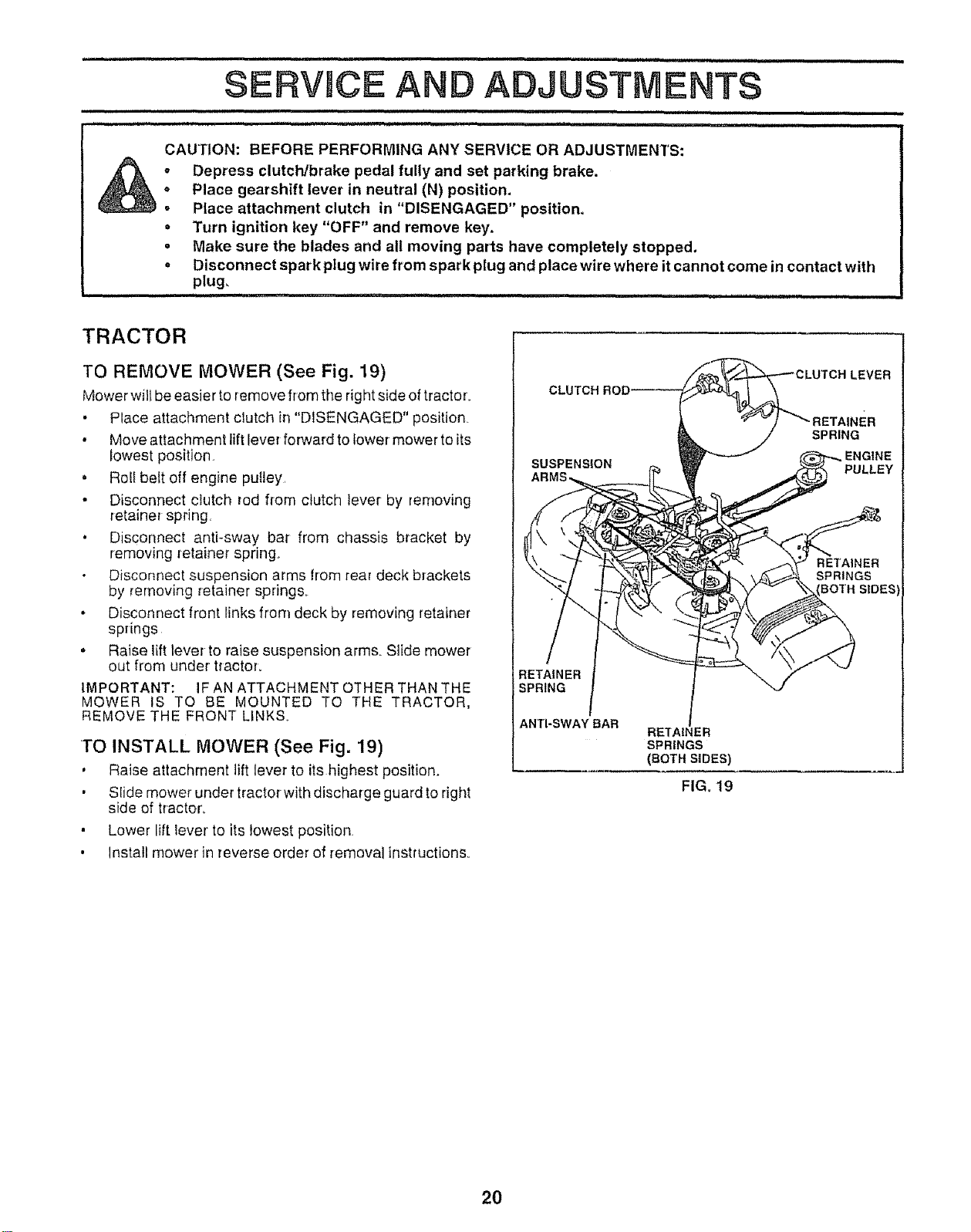
TO REMOVE MOWER (See Fig. 19)
Mower will be easier to remove from the right side of tractor°
• Place attachment clutch in "DISENGAGED" position.
• Move attachment lift lever forward to Iower mower to its
lowest position
. Roll belt off engine putley,
• Disconnect dutch rod from clutch lever by removing
retainer spring.
. Disconnect antFsway bar from chassis bracket by
removing retainer spring.
Oiscormect suspension arms from rear deck brackets
by removing retainer spring&
• Disconnect front Iinks from deck by removing retainer
springs
• Raise lift lever to raise suspension arms Slide mower
out from under tractor.
IMPORTANT: IF AN ATTACHMENT OTHER THAN THE
MOWER tS TO 8E MOUNTED TO THE TRACTOR,
REMOVE THE FRONT LfNKS,.
TO INSTALL MOWER (See Fig. 19)
, Raise attachment lift lever to its highest position.
, Slide mower under tractor with discharge guard to right
side of tractor,
• Lower lift lever to its lowest position
, Install mower in reverse order of removal instructions
LEVER
SUSPENSION
SPRING
PULLEY
RETAINER
SPRINGS
BOTH SLDE_
RETAINER
SPRING
ANTI-SWAY BAR
RE"[AINER
SPRINGS
(BOTH SIDES)
FIG, 19
2O
SERVICE ANO ADJUSTMENTS
TO LEVEL MOWER HOUSING
Adjust the mower while tractor is parked on level ground or
driveway. Make sure tires are properly inflated (See
"PRODUCT SPECIFICATIONS"on page 3ofthis manual)°
If tires are over or underinflated, you will not properly adjust
your mower.
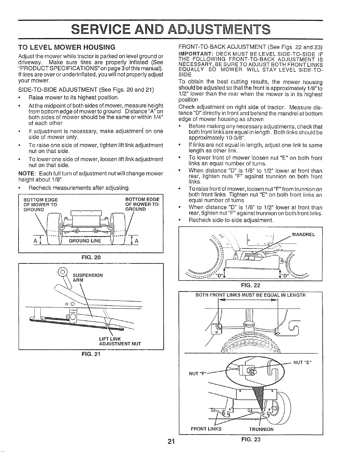
SIDE-TO-SIDE ADJUSTMENT (See Figs. 20 and 21)
• Raise mower to its highest position.
• At the midpoint of both sides of mower, measure height
from bottom edge of mower to ground Distance' A" on
both sides of mower should be the same or within 1/4"
of each other
If adjustment is necessary, make adjustmen{ on one
side of mower only.
• To raise one side of mower, tighten lift link adjustment
nut on that side.
o To lower one side of mower, loosen lift link adjustment
nut on that side.
NOTE: Each full turn of adjustment nut will change mower
height about t/8".
• Recheck measurements after adjusting
BOTTOM EDGE BOTTOM EDGE
OF MOWER TO OF MOWER TO
GROUND GROUND
GROUND LINE A
FIG. 20
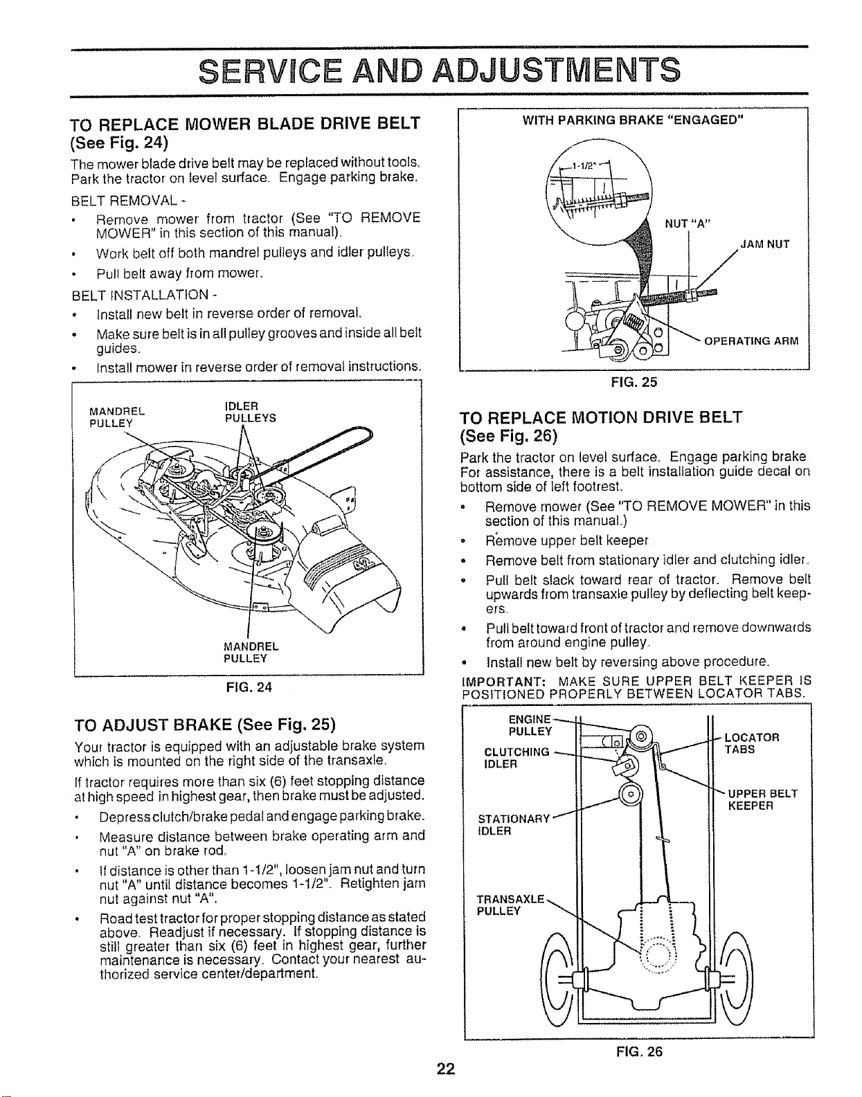
SUSPENSION
ARM
LIFT LINK
ADJUSTMENT NUT
FIG. 21
FRONT-TO-BACK ADJUSTMENT (See Figs 22 and 23)
IMPORTANT: DECK MUST BE LEVEL SIDE-TO-SIDE IF
THE FOLLOWING FRONT-TO-BACK ADJUSTMENT 18
NECESSARY, BE SURE TO ADJUST BOTH FRONT LINKS
EQUALLY SO MOWER WILL STAY LEVEL SIDE-TO-
SIDE
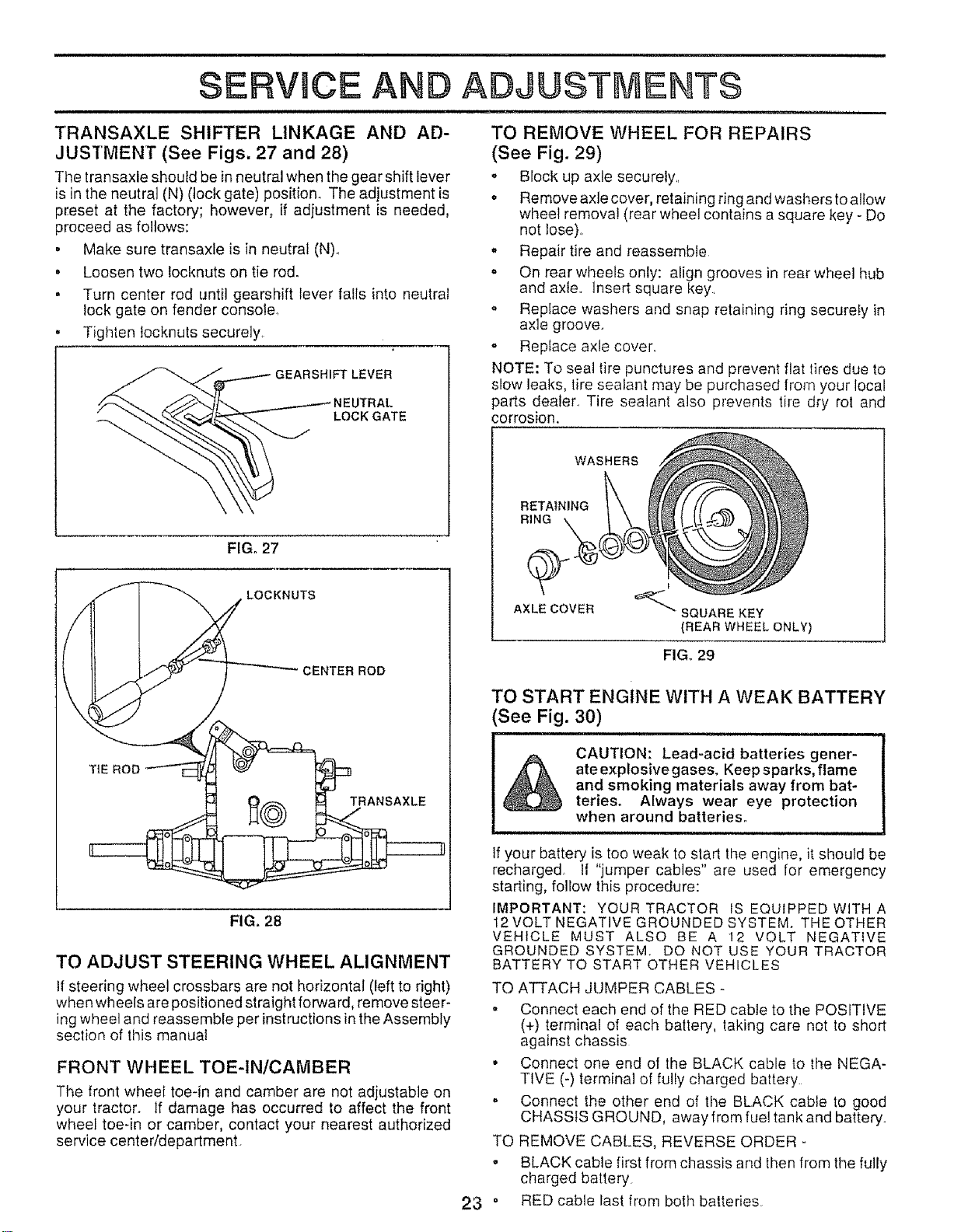
To obtain the best cutting results, the mower housing
should be adjusted so that the front is approximately 1/8" to
1/2" lower than the rear when the mower is in its highest
position.
Check adjustment on right side of tractor_ Measure dis-
tance"D" directly in front and behind the mandrel at bottom
edge of mower housing as shown
. Before matdng any necessary adjustments, check that
both front links are equal in length. Both links should be
approximately 10-3/8".
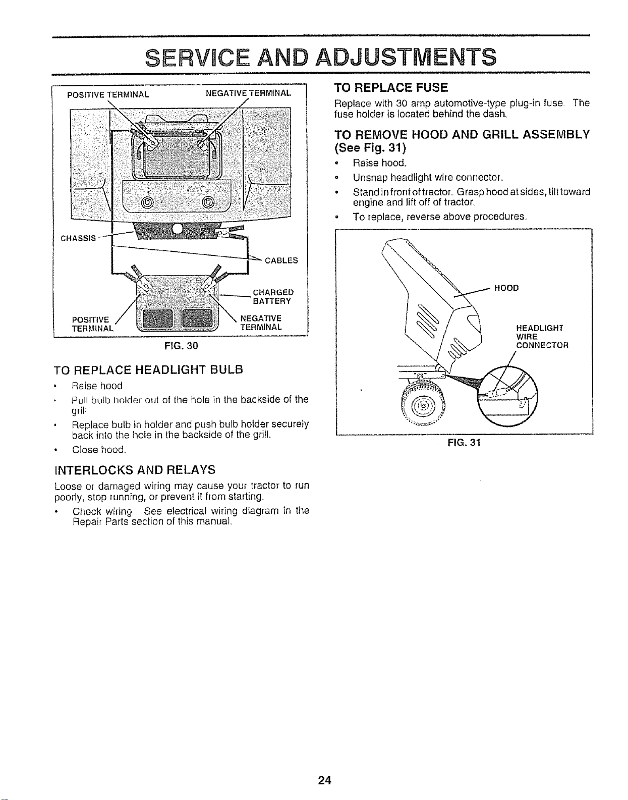
o If links are not equal in length, adjust one link to same
Iength as other linko
" To lower front of mower loosen nut "E" on both front
links an equal number of turns.
o When distance "D" is 1/8" to 1/2" lower at front than
rear, tighten nuls "F" against trunnion on both front
links
o To raise front of mower, loosen nut"F" from trunnion on
both front links Tighten nut "E" on both front links an
equal number of turns
° When distance "D" is I/8" to 1t2" lower at front than
rear, tighten nut "F" against trunnion on both front links..
o Recheck side-to-side adjustment.
,,,:_ _:_ .... _ MANDREL
FIG. 22
BOTH FRONT LINKS MUST BE EQUAL IN LENGTH
NUT "F"_ NUT "E"
FRONT LINKS TRUNNION
21 FIGo 23
SERVmCE AND ADJUSTMENTS
u,, ,,, = ,ran,,= =nnun 11,nu,,,,,H,
WITH PARKINGBRAKE "ENGAGED"
TO REPLACE MOWER BLADE DRIVE BELT
(See Fig. 24)
The mower blade drive belt may be replaced without tool&
Park the tractor on level surface. Engage parking brake.
BELT REMOVAL -
* Remove mower from tractor (See "TO REMOVE
MOWER" in this section of this manua0_
, Work belt off both mandrel pulleys and idler pulIeys.
. Pull belt away from mower.
BELT INSTALLATION -
. Install new belt in reverse order of removal.
o Make sure belt isinall pulley grooves and insideall belt
guides°
, Install mower in reverse order of removal instructions.
MANDREL IDLER
PULLEY PULLEYS
MANDREL
PULLEY
FIG. 24
FIG. 25
TO REPLACE MOTION DRIVE BELT
(See Fig. 26)
Park the tractor on level surface_ Engage parking brake
For assistance, there is a belt installation guide decal on
bottom side of left footrest.
, Remove mower (See "TO REMOVE MOWER" in this
section of this manual.)
• Remove upper belt keeper
• Remove belt from stationary idler and clutching idler,
o Pull belt slack toward rear' of tractor. Remove belt
upwards from transaxte pulley by deflecting belt keep-
ers
• Pull belt toward front of tractor and remove downwards
from around engine pulley,
• Install new belt by reversing above procedure.
IMPORTANT: MAKE SURE UPPER BELT KEEPER IS
POSITIONED PROPERLY BETWEEN LOCATOR TABS.
TO ADJUST BRAKE (See Fig, 25)
Your tractor is equipped with an adjustable brake system
which is mounted on the right side of the transaxle.
If tractor requires more than six (6) feet stopping distance
at high speed in highest gear, then brake must be adjusted.
Depress clutch!brake pedal and engage parking brake.
Measure distance between brake operating arm and
nut "A" on brake rod._
tf distance is other than 1°1/2", loosen jam nut and turn
nut "A" until distance becomes 1-1/2". Retighten jam
nut against nut "A".
• Road test tractor for proper stopping distance as stated
above. Readjust if necessary. If stopping distance is
still greater than six (6) feet in highest gear, further
maintenance is necessary. Contact your nearest au-
thorized service center/departmento
PULLEY LOCATOR
CLUTCHING TABS
IDLER
STATIONARY
IDLER
TF
PULLEY
UPPER BELT
KEEPER
22
FIG. 26
TRANSAXLE SHIFTER LINKAGE AND AD-
JUSTMENT (See Figs. 27 and 28)
The transaxle should be inneutral when the gear shift lever
is in the neutral (N) (lock gate) position. The adjustment is
p_eset at the factory; however, if adjustment is needed,
proceed as foJtows:
• Make sure transaxle is in neutral (N).
. Loosen two locknuts on tie rod.
° Turn center rod until gearshift lever falls into neutral
lock gate on fender console_
° Tighlen tocknuts securely,
LEVER
LOCK GATE
FIG. 27
LOCKNUTS
CENTER ROD
TiE ROD
FIG. 28
TO ADJUST STEERING WHEEL ALIGNMENT
tf steering wheel crossbars are not horizontal (left to right)
when wheels are positioned straight forward, remove steer-
ing wheel and reassemble per instructionsin the Assembly
section of this manual
FRONT WHEEL TOE-IN/CAMBER
The front wheel toe-in and camber are not adjustable on
your tractor. If damage has occurred to affect the front
wheel toe-in or camber, contact your nearest authorized
service centerldepartment
TO REMOVE WHEEL FOR REPAIRS
(See Fig, 29)
o Block up axle securely..
. Remove axle cover, retaining ring and washers to allow
wheel removal (rear wheel contains a square key - Do
not lose).,
,, Repair tire and reassemble
,' On rear wheels only: align grooves in rear wheel hub
and axle,. Insert square key.
o Replace washers and snap retaining ring securefy in
axle groove.
- Repiace axle cover..
NOTE: To seal tire punctures and prevent flat tires due to
slow leaks, tire sealant may be purchased from your local
parts deater_ Tire sealant also prevents tire dry rot and
corrosion.
WASHERS
RETAINING
RING
AXLE COVER
I
'_"" SQUARE KEY
(REAR WHEEL ONLY)
FIGo29
TO START ENGINE WITH A WEAK BATTERY
See Fig. 30)
CAUTION: Lead-acid batteries gener-
ate explosivegases. Keep sparks, flame
and smoking materials away from bat-
teries. Always wear eye protection
when around batteries.
If your battery is too weal< to start tile engine, it should be
recharged !{ "jumper cables" are used for emergency
starting, follow this procedure:
IMPORTANT: YOUR TRACTOR IS EQUIPPED WITH A
12 VOLT NEGATIVE GROUNDED SYSTEM. THE OTHER
VEHICLE MUST ALSO BE A 12 VOLT NEGATIVE
GROUNDED SYSTEM. DO NOT USE YOUR TRACTOR
BATTERY TO START OTHER VEHICLES
TO ATTACH JUMPER CABLES
,, Connect each end of the RED cable to the POSITIVE
(+) terminal of each battery, taking care not to short
against chassis
" Connect one end of the BLACK cable to the NEGA-
TIVE (-) terminal of fully charged battery.
o Connect the other end of the BLACK cable to good
CHASSIS GROUND, away from fuel tank and battery,
TO REMOVE CABLES, REVERSE ORDER -
,, BLACK cable first from chassis and Ihen from the fully
charged battery
23 ° RED cable last from both batteries
= ==l=l=lllll ii =,I,J=,J,JJ:IL,=_=U ,H==I==,I=I = == = == H=== = I
SERVmCE AN ADJUSTMENTS
POSITIVE TERMINAL NEGATIVE TERMINAL
CABLES
CHARGED
BATTERY
POSITIVE NEGATIVE
TERMINAL TERMINAL
FIG. 30
TO REPLACE HEADLIGHT BULB
, Raise hood
Pull bulb holder out of the hole in the backside of the
grill
Replace bulb in holder and push bulb holder securely
back into the hole in the backside of the grill
• Close hood,,
TO REPLACE FUSE
Replace with 30 amp automotive-type plug-in fuse, The
fuse holder is iocated behind the dash_
TO REMOVE HOOD AND GRILL ASSEMBLY
(See Fig. 31)
- Raise hood°
. Unsnap headlight wire connector,,
o Stand in front of tractor, G rasp hood at sides, tilt toward
engine and lift off of tractor
- To replace, reverse above procedures,
\
\
\
HOOD
HEADLIGHT
WIRE
CONNECTOR
FIG. 31
INTERLOCKS AND RELAYS
Loose or damaged wiring may cause your' tractor to run
poorly, stop running, or prevent it from starting
. Check wiring See electrical Wiring diagram in the
Repair Parts section of this manual.
24
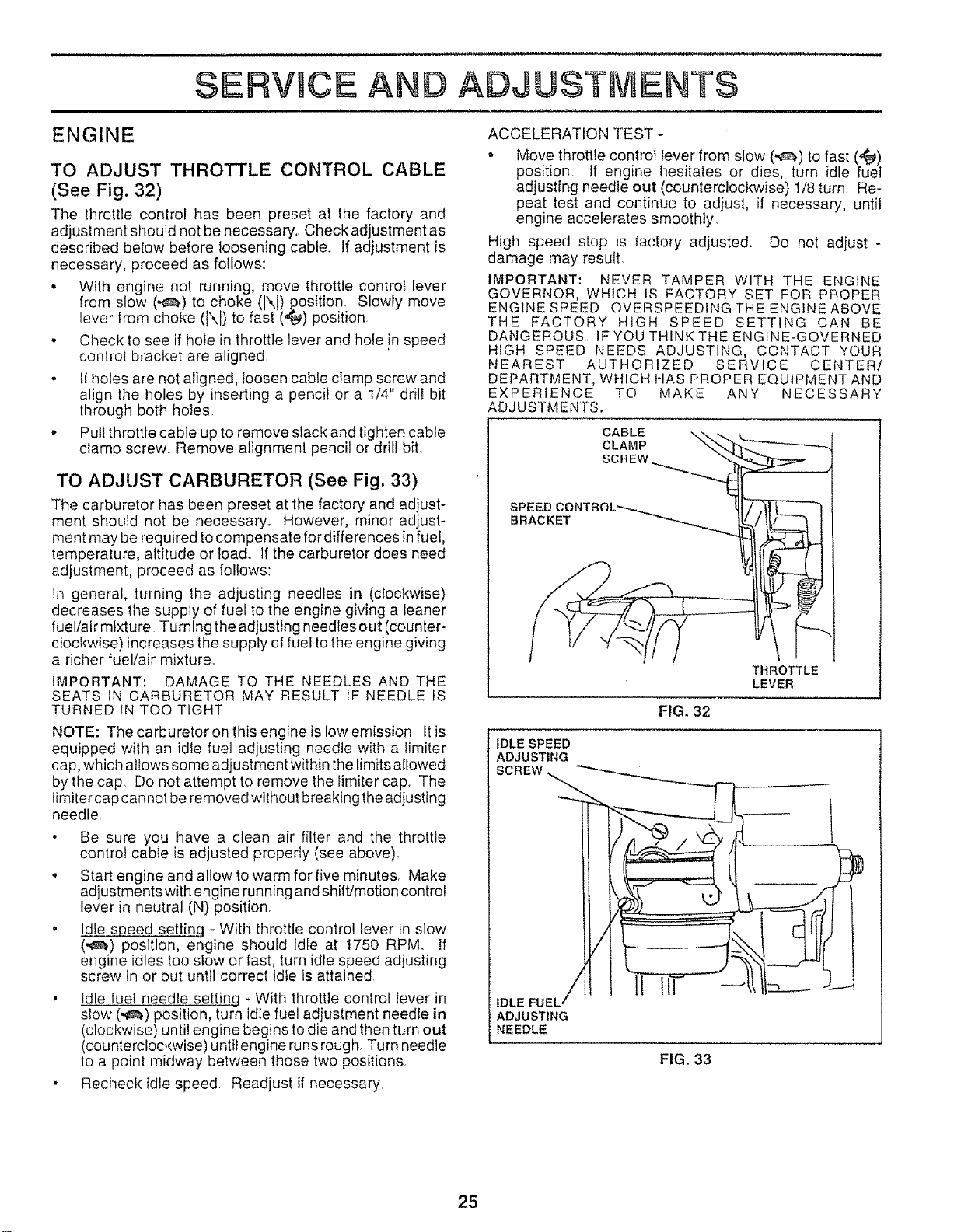
TO ADJUST THROTTLE CONTROL CABLE
(See Fig. 32)
The throttle control has been preset at the factory and
adjustment should not be necessary. Check adjustment as
described below before loosening cable. If adjustment is
necessary, proceed as follows:
• With engine not running, move throttle control lever
from slow (,e_) to choke (\) position Slowly move
lever from choke (N) to fast ('_) position
• Check to see if hole in throttle lever and hole !n speed
control bracket are aligned
• it holes are not aligned, toosen cable clamp screw and
align the holes by inserting a pencil or a 1/4" drill bit
through both hoies.
• Putt throttle cable up to remove slack and tighten cable
ciamp screw. Remove alignment pencil or drill bit
o Move throttle control lever from stow (,,,_.) to fast (,,_)
position If engine hesitates or dies, turn idle fuel
adjusting needle out (counterclockwise) 1/8 turn Re-
peat test and continue to adjust, if necessary, until
engine accelerates smoothly°
High speed stop is factory adjusted. Do not adjust -
damage may result.
IMPORTANT: NEVER TAMPER WITH THE ENGINE
GOVERNOR, WHICH IS FACTORY SET FOR PROPER
ENGINE SPEED OVERSPEEDINGTHEENGtNEABOVE
THE FACTORY HIGH SPEED SETTING CAN BE
DANGEROUS IFYOUTHINKTHEENGINE-GOVERNED
HiGH SPEED NEEDS ADJUSTING, CONTACT YOUR
NEAREST AUTHORIZED SERVICE CENTER/
DEPARTMENT, WHICH HAS PROPER EQUIPMENT AND
EXPERIENCE TO MAKE ANY NECESSARY
ADJUSTMENTS.
TO ADJUST CARBURETOR (See Fig. 33)
The carburetor has been preset at the factory and adjust-
ment should not be necessary_ However, minor adjust-
ment may be required to compensate for differences in fuel,
temperature, altitude or toado If the carburetor does need
adjustment, proceed as follows:
tn general, turning lhe adjusting needles in (clockwise)
decreases the supply of fuel to the engine giving a leaner
fuel/air mixture Turning the adjusting needles out (counter-
clockwise) increases the supply of fuel to the engine giving
a richer fuel/air mixture.
IMPORTANT: DAMAGE TO THE NEEDLES AND THE
SEATS IN CARBURETOR MAY RESULT IF NEEDLE IS
TURNED IN TOO TIGHT
NOTE: The carburetor on this engine is Iow emission. It is
equipped with an idle fuel adjusting needle with a timiter
cap, whictl allows some adjustment within the limits allowed
by the cap. Do not attempt to remove the fimiter cap. The
limiter cap cannot be removed without breaking the adjusting
needle
° Be sure you have a clean air filter and the throttle
control cable is adjusted properly (see above).
• Start engine and allow to warm for five minutes. Make
adjustments with engine running and shift/motion control
lever in neutral (N) position..
• Idle speed setting - With throttle control lever in slow
(,,,,_,) position, engine should idle at 1750 RPM If
engine idles too slow or fast, turn idle speed adjusting
screw in or out until correct idle is attained
, Idle fuel needle settinq - With throttle control lever in
stow (,_.) position, turn idle fuel adjustment needle in
(clockwise) until engine begins to die and then turn out
(counterclockwise) until engine runs rough. Turn needle
lo a point midway between those two positions
• Recheck idle speed. Readjust if necessary..
CABLE ,_
CLAMP
SCREW_
SPEED CONTROL"--..,..,.,.._
BRACKET _"_-._
THROTTLE
LEVER
FIG. 32
IDLE SPEED
ADJUSTING
IDLE FUEL'
ADJUSTING
NEEDLE
FIG. 33
25
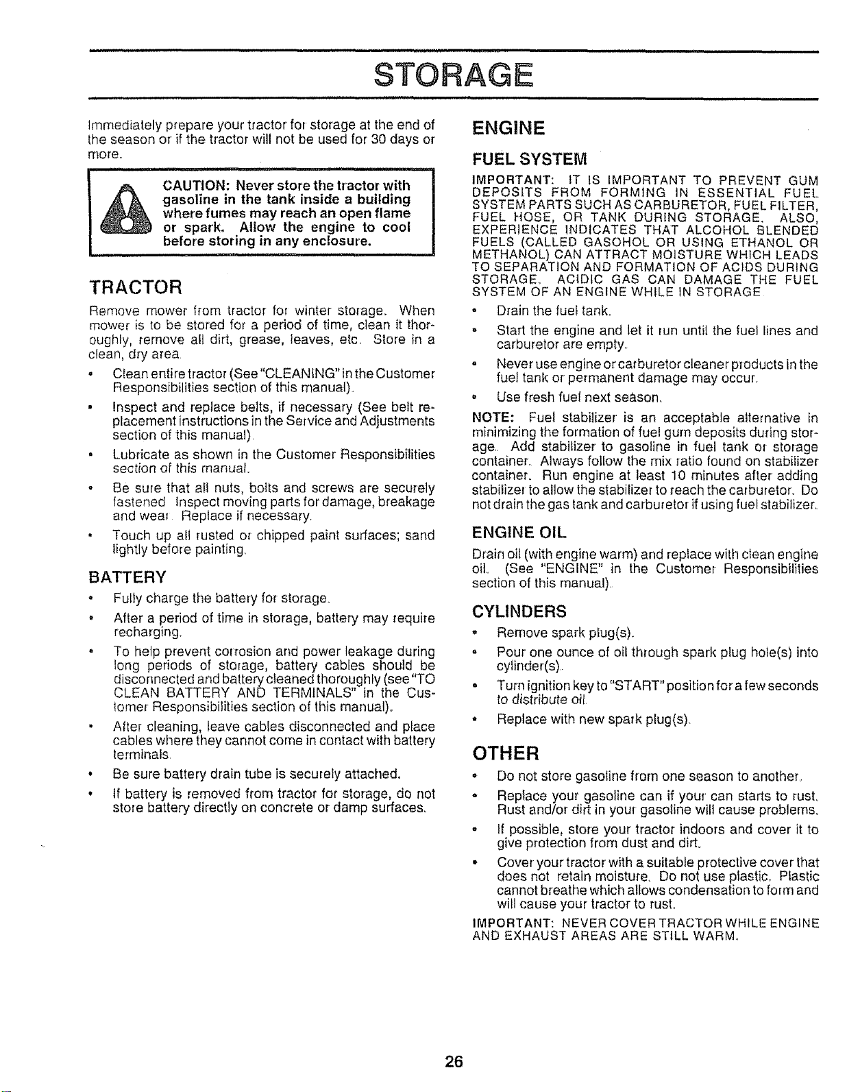
STORAGE
,, ,, , , i, i ,,,,i ,,, ,,,,, i ,i,,,,l,,,,ul,,,l,
Immediately prepare your tractor for storage at the end of
the season or if the tractor will not be used for 30 days or
more..
!
CAUTION: Never store the tractor with
gasoline in the tank inside a building
where fumes may reach an open flame
or spark, Allow the engine to cool
before storing in any enclosure.
, i, ,,,H, ll,,,,,H,,,,l,
TRACTOR
Remove mower from tractor for winter storage.. When
mower is to be stored for a period of time, clean it thor-
oughfy, remove all dirt, grease, leaves, etc. Store in a
clean, dry area
• Clean enti re tractor (See "CLEANING" in the Customer
Responsibilities section of this manual).
• Inspect and replace belts, if necessary (See belt re-
placement instructions in the Service and Adjustments
section of this manual)
• Lubricate as shown in the Customer Responsibilities
section of this manual
,, Be sure that all nuts, bolts and screws are securely
fastened inspect moving parts fordamage, breakage
and wear Replace if necessary.
• Touch up alt rusted or chipped paint surfaces; sand
lightly before painting.
BATTERY
• Fully charge the battery for storage.
• After a period of time in storage, battery may require
recharging.
, To help prevent corrosion and power' leakage during
tong periods of storage, battery cables should be
disconnected and battery cleaned thoroughly (see "TO
CLEAN BATTERY AND TERMINALS" in the Cus-
lomer Responsibilities section of this manual).
• AIter cleaning, leave cables disconnected and place
cables where they cannot come in contact with battery
lerminals.
• Be sure battery drain tube is securely attached.
• tf battery is removed from tractor for storage, do not
store battery directly on concrete or damp surfaces.
ENGINE
FUEL SYSTEM
IMPORTANT: IT IS IMPORTANT TO PREVENT GUM
DEPOSITS FROM FORMING IN ESSENTIAL FUEL
SYSTEM PARTS SUCH AS CARBURETOR, FUEL FILTER,
FUEL HOSE, OR TANK DURING STORAGE. ALSO,
EXPERIENCE INDICATES THAT ALCOHOL BLENDED
FUELS (CALLED GASOHOL OR USING ETHANOL OR
METHANOL) CAN ATTRACT MOISTURE WHICH LEADS
TO SEPARATION AND FORMATION OF ACIDS DURING
STORAGE. ACIDIC GAS CAN DAMAGE THE FUEL
SYSTEM OF AN ENGINE WHILE IN STORAGE
• Drain the fuel tank.
o Start the engine and let it run until the fuel lines and
carburetor are empty.
,, Never use engine or carburetor cleaner products in the
fuel tank or permanent damage may occur
• Use fresh fuel next season
NOTE: Fuel stabilizer is an acceptable alternative in
minimizing the formation of fuel gum deposits dudng stor-
age. Add stabilizer to gasoline in fuel tank or storage
container, Always follow the mix ratio found on stabilizer
container. Run engine at least 10 minutes after adding
stabilizer to allow the stabilizer to reach the carburetor. Do
not drain the gas tank and carburetor if using fuel stabilizer..
ENGINE OIL
Drain oil (with engine warm) and replace with clean engine
oil (See "ENGINE" in the Customer Responsibilities
section of this manual).
CYLINDERS
• Remove spark plug(s).
o Pour one ounce of oil through spark plug hole(s) into
cylinder(s).
o Turn ignition key to"START" position for a few seconds
to distribute oil
o Replace with new spark plug(s).
OTHER
o Do not store gasoline from one season to another_
° Replace your gasoline can if your can starts to rust°
Rust and/or dirt in your gasoline will cause problems..
o If possible, store your tractor indoors and cover it to
give protection from dust and dirt.
o Cover your tractor with a suitable protective cover that
does not retain moisture. Do not use plastic. Plastic
cannot breathe which allows condensation to form and
will cause your tractor to rust°
IMPORTANT: NEVER COVER TRACTOR WHILE ENGINE
AND EXHAUST AREAS ARE STILL WARM.
26

i = ....................
TRO LESHOOTtNG POHNTS
PROBLEM CAUSE CORRECTION
Will not start
Hard to start
1 Out of fuel
2, Engine not "CHOKED" propedy
3 Engine flooded.
4 Bad sparkptug
5 Dirty air fitter
6 Dirty fuel filter
7 Water in fuel
8 Loose or damaged wiring
9 Carburetor out of adjustment
!0 Engine valves out of adjustment,
1 Fill fuel tank
2 See "TO START ENGINE" in Operation section
3 Wait several minutes before attempting to sled.,
4 Replace spark ptug,
5 Clean/replace air litter
6 Replace fuel filter,
7 Drain fuel tank and carburetor, refill tank with flesh
gasoline and replace fuel filter
8 Check all wiring
9 See "To Adjust Carburetor" in Service Adjustments
section
!0 Contact an authorized service centeridepartmenl
1 Dirty air filter
2 Bad spark plug
3 Weak or dead battery
4 Dirty fuel fi_ter
5 Staie or dirty fuel
6 Loose or damaged wiring
7 Carburetor out of adjustment
! Clean/replace air filter
2. Replace spark plug
3, Recharge or replace battery
4 Replace fuel filter
5 Drain fuel tank and refill with fresh gasoline
6 Check ell wiring
7 See "To Adjust Carburetor" in Service Adjustments
section
Engine wilt not lurn over
Engine clicks but will not
start
Loss of power
8 Engine valves out of adjustment,
1 Clutch/brake pedal not depressed
2 Attachment clutch is engaged
3 Weak or dead baltery,
4 Blown fuse
5 Corroded battery terminals
6 Loose or damaged wiring
7 Faulty ignition swilch
8. Faulty solenoid or starter
9. Faulty operator presence switch(es)
1. Weaker dead battery.
2 Corroded battery terminals
3. Loose or damaged wiring
4 Faulty solenoid or starter
1 Cutting too much grass/leo fast
2 Throttle in "CHOKE" position
3 Build-up of grass, leaves and trash under mower
8 Confact an authorized service center/department
1 Depress c_utchlbrake pedal
2 Disengage allachment clutch
3 Recharge or replace battery
4 Replace luse
5 Clean battery terminals
6 Check all wiring
7 Check/replace ignition switch
8 Chectdreplace solenoid or starter
9 Contact an authorized service center/department
1, Recharge or replace baltery
2, Clean battery terminals
3 Check nil wiring,
4 ChecWrep_ace solenoid or starter
1 Set in "Higher Cut" posilionireduce speed
2 Adjust throttle control
3 Clean underside of mower housing
4 Dirty air filter
5 Low oil level/dirty oil
6 Faully spark plug
7 Dirty fuel filler
8 Stale or dirty IueJ
9 Water in fuel
10 Spark plug wire loose,
11 Dirty engine air screenlflns
12 Didy/c]ogged muffler
t 3 Loose or damaged wiring,
4 Clean!replace air filter
5 Check oil level/change oil
6 Clean and regap or change spark plug
7 Replace fuel filter
8 Drain rue] tank and refill with fresh gasoline
9 Drain fuel tank and carburetor, refill tank with fresh
gasoline and replace fuel filter
10 Connect and lighten spark plug wire
1I, Clean engine air screen/fins
12 Clean/replace muffler
13 Check all wiring
Excessive vibration
! 4 Carburetor out of adiustment
15 Engine valves out of adjustment
t Worn, bent or loose blade
2 Benl blade mandrel
3 Loose/damaged part(s}
14 See 'To Adjust Carburelor" in Service Adjustments
section
15 Contact an authorized service center/department
1 Replace blade Tighten btade bolt
2 Replace blade mandrel,
3 Tighten loose part(s) Replace damaged parts
27

TROUBLESHOOTING POINTS
PROBLEM CAUSE CORRECTION
i , i u,u,,,,,,, u, i,,
Engine continues to run
when operator leaves seat
with attachment clutch
engaged
z)oorcut-uneven
Mower blades will not
rotate
,,:oor grass discharge
Headlight(s} not working
th so equipped)
,,,,,, u i,,,,,
Battery will not charge
Engine "backfires"
when turning engine
OFF"
Ull i inl ,,UlU,,
Faulty operator-safety presence control system
1 Worn, bent or loose blade
2 Mower deck not level
3 BuiIdup of grass, leaves, and trash under mower
4 Bent blade mandret
5 Clogged mower deck vent holes from buildup of
grass, leaves, and trash around mandrels
1_ Check wiring, switches and connections If not
corrected, contact an authorized service center/
department
1 Replace blade Tighten blade bolt
2 Level mower deck
3 Clean underside of mower housing
4 Replace blade mandrel
5 Clean around mandrels to open vent holes
t Obstruction in clutch mechanism
2 Worn/damaged mower drive belt
3 Frozen idler pulley
4 Frozen blade mandrel
t Engine speed too slow
2 Travef speed too last
3 Wet grass
4 Mower deck not level
5 Low/uneven tire air pressure
6 Worn, bent or{oose blade,
7 Buildup of grass, leaves and trash under mower
8 Mower drive belt warn
9 Blades improperly installed
10 improper blades used
1l, Clogged mower deck vent holes from buildup of
grass, leaves, and trash around mandrels
! Remove obstruction
2 Replace mower drive belt
3 Replace idler pulley
4 Replace blade mandrel
t Place throttle control in "FAST" position
2 Shift to slower speed,
3 Allow grass to dry before mowing
4 Level mower deck
5 Check tires for proper air pressure
6 Replace/sharpen blade Tighfen blade bolt
7 Ctean underside of mower housing
8 Replace mower drive beff
9 Reinstall blades sharp edge down
10 Replace with blades listed in this manual
11 Clean around mandrels to open vent holes
1 Switch is "OFF"
2 Bulb(s) burned out
3 Faulty light switch
4 Loose or damaged wiring
5 Blown fuse
i, Bad battery cell(s)
2, Poor eabte conneclions
3, Faulty regulator (if so equipped)
4 Faulty a]Iemator
Engine throttle control not set at "SLOW"
position for 30 seconds before stopping engine,
1 Turn switch "ON'
2 Replace bulb(s)
3 Checidreplace tight switch
4_ Check wiring and connections .......
5, Replace fuse
1 Replace battery,
2, Check!clean ail connections
3. Replace regulator
4 Replace afternator
Move throttle control to "SLOW" position and allow
to idle for 30 seconds before stopping engine
28


