Loading ...
Loading ...
Loading ...
Part number 550-100-260/0520
48
ECO
®
Tec
GAS-FIRED WATER BOILER – 80/110/150/199 BOILER MANUAL
:
Install relief valve ONLY with the spindle
vertical, as shown in illustrations in this
manual.
Discharge line must be connected to relief
valve outlet and run to a safe place of disposal.
Terminate the discharge line in a manner that
will prevent possibility of severe burns or
property damage should the valve discharge.
Locate away from the top of the boiler.
Discharge line must be as short as possible
and be the same size as the valve discharge
connection throughout its entire length.
Discharge line must pitch downward from
the valve and terminate at least 6" above the
floor drain where any discharge will be clearly
visible.
The discharge line shall terminate plain, not
threaded, with a material serviceable for
temperatures of 375 °F or greater.
Do not pipe the discharge to any place where
freezing could occur.
No shutoff valve shall be installed between the
relief valve and boiler, or in the discharge line.
Do not plug or place any obstruction in the
discharge line.
Test the operation of the valve after filling and
pressurizing system by lifting the lever. Make
sure the valve discharges freely. If the valve fails
to operate correctly, replace it with a new relief
valve.
Failure to comply with the above guidelines
could result in failure of the relief valve to
operate, resulting in possibility of severe
personal injury, death or substantial property
damage.
Install relief valve
1. Install relief valve in a 3/4" street elbow along with a 3/4"
tee onto the top water pipe – Air elimination/relief valve
(Figure 8, page 13).
the boiler out. Connect the
relief valve only as shown in this manual. Ensure
relief valve is located above heat exchanger.
2. Pipe the relief valve only as shown, in the location shown.
3. Connect discharge piping to safe disposal location,
following guidelines in the WARNING below.
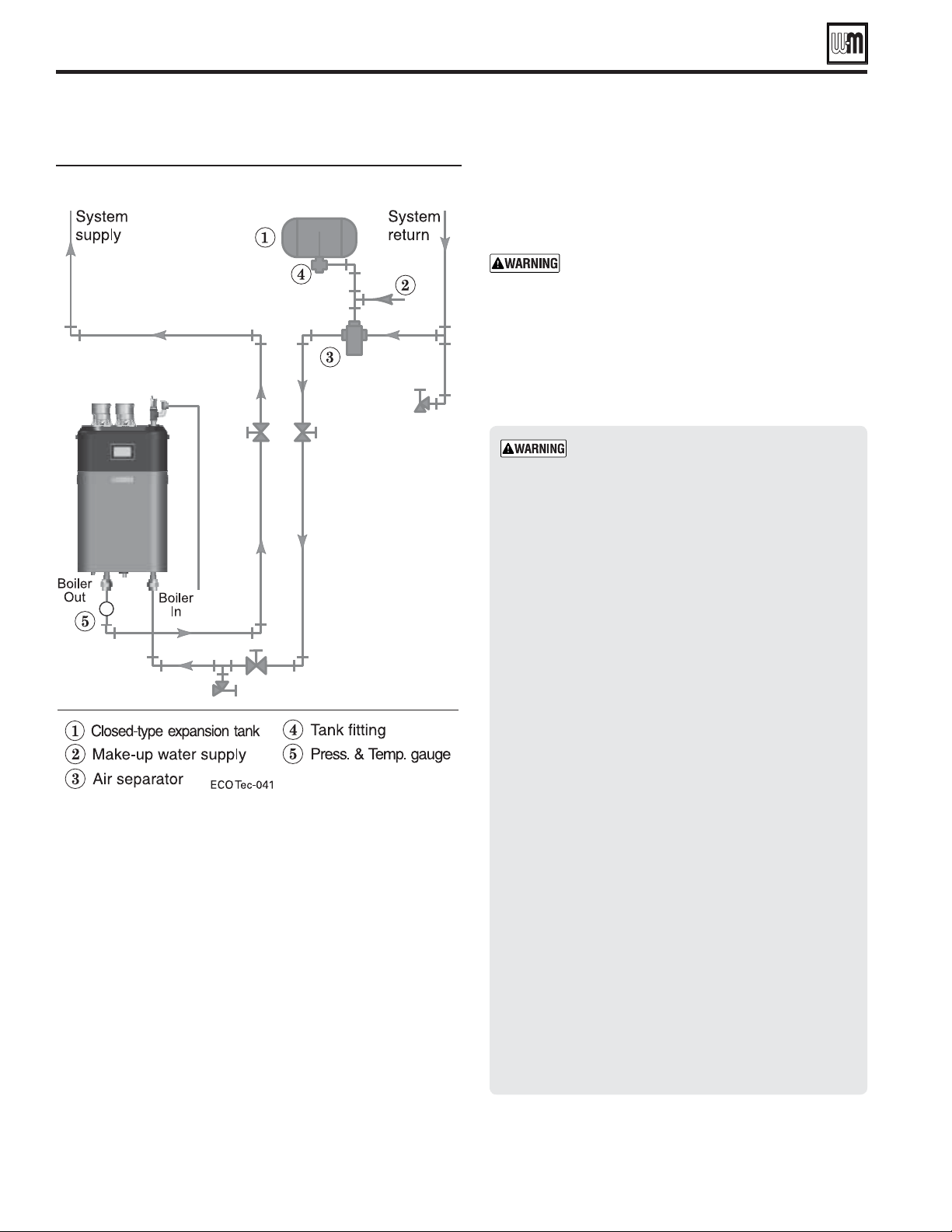
Piping to closed-type expansion tank
Direct Connect System Piping - Single Boiler System (continued)
80/110/150 Boilers only
Loading ...
Loading ...
Loading ...