This manual must only be used by a qualifi ed heating installer/service technician. Read all instructions, including this manual and
all other information shipped with the boiler, before installing. Perform steps in the order given. Failure to comply could result in
severe personal injury, death or substantial property damage.
Part number 550-100-260/0520
Boiler Manual
80/110/150/199
Part number 550-100-260/0520
2
ECO
®
Tec
GAS-FIRED WATER BOILER – 80/110/150/199 BOILER MANUAL
Contents
The ECO Tec Gas-fired water boilers . . . . . . . . . . . . . 3
Please read before proceeding . . . . . . . . . . . . . . . . 6
Boiler location . . . . . . . . . . . . . . . . . . . . . . . . . 7
Prepare boiler location. . . . . . . . . . . . . . . . . . . . . 9
Wall-mounting the boiler. . . . . . . . . . . . . . . . . . . 10
Boiler hydrostatic test . . . . . . . . . . . . . . . . . . . . 12
Gas conversions . . . . . . . . . . . . . . . . . . . . . . . 14
Gas piping — sizing gas lines . . . . . . . . . . . . . . . . 19
Venting/air piping — general . . . . . . . . . . . . . . . . 20
Commonwealth of Massachusetts installations . . . . . . 24
Vent termination requirements . . . . . . . . . . . . . . . 25
Boiler room air openings. . . . . . . . . . . . . . . . . . . 26
Vent and air piping and boiler connections . . . . . . . . . 27
DIRECT VENT — Sidewall with separate pipes . . . . . . . 28
DIRECT VENT — Sidewall concentric . . . . . . . . . . . . 30
DIRECT VENT — Sidewall with W-M vent/air plate . . . . . 32
DIRECT VENT — Vertical with separate pipes. . . . . . . . 34
DIRECT VENT — Vertical concentric. . . . . . . . . . . . . 36
DIRECT VENT — Vertical vent /sidewall air . . . . . . . . . 38
Concentric termination, typical (sidewall or vertical). . . . 40
Install boiler water piping . . . . . . . . . . . . . . . . . . 41
Direct Connect System Piping - Single Boiler System 80/110/150
Boilers only . . . . . . . . . . . . . . . . . . . . . . . . . 46
Verify the application will work: . . . . . . . . . . . . . . . . . 46
Expansion tank location. . . . . . . . . . . . . . . . . . . . . . 46
Diaphragm- or bladder-type tank: . . . . . . . . . . . . . . . . 46
Closed-type expansion tank: . . . . . . . . . . . . . . . . . . . 47
Install relief valve . . . . . . . . . . . . . . . . . . . . . . . . . 48
ZONE VALVE zoning – direct connection . . . . . . . . . . . . . 49
Primary/Secondary System Piping - Single Boiler System . 50
Expansion tank location. . . . . . . . . . . . . . . . . . . . . . 50
Diaphragm- or bladder-type tank: . . . . . . . . . . . . . . . . 50
Closed-type expansion tank . . . . . . . . . . . . . . . . . . . 50
Install relief valve . . . . . . . . . . . . . . . . . . . . . . . . . 51
System water piping methods . . . . . . . . . . . . . . . . . . 52
ZONE VALVE zoning – primary/secondary . . . . . . . . . . . . . . . 53
Circulator zoning – primary/secondary . . . . . . . . . . . . . . . . 54
Circulator zoning – Multiple temperature zones with primary/secondary . 55
Install condensate drain line & trap assembly . . . . . . . 56
Gas piping . . . . . . . . . . . . . . . . . . . . . . . . . . 57
Field wiring . . . . . . . . . . . . . . . . . . . . . . . . . . 58
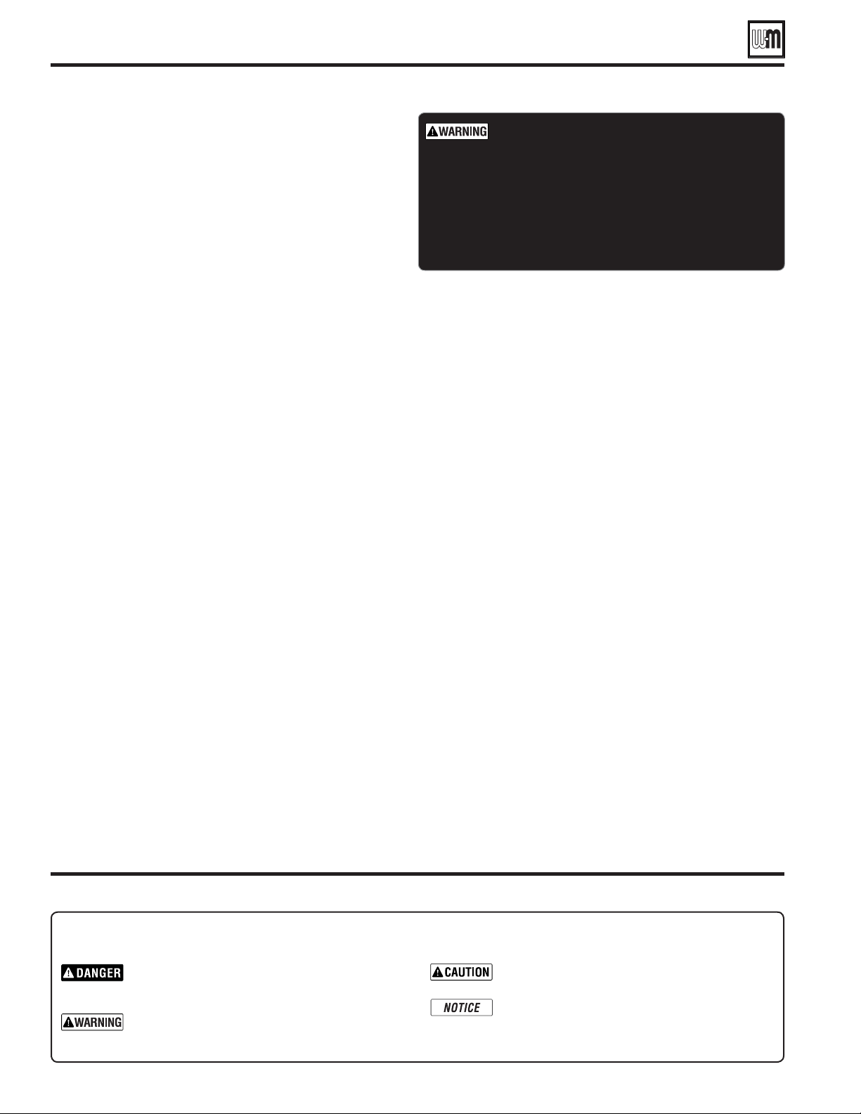
The following defined terms are used throughout this manual to bring attention to the presence of hazards of various risk levels
or to important information concerning the life of the product.
Indicates presence of hazards that will cause severe
personal injury, death or substantial property
damage.
Indicates presence of hazards that can cause severe
personal injury, death or substantial property
damage.
Indicates presence of hazards that will or can
cause minor personal injury or property damage.
Indicates special instructions on installation,
operation or maintenance that are important
but not related to personal injury or property
damage.
Hazard definitions
Wiring diagram — schematic . . . . . . . . . . . . . . . . 66
Wiring diagram — ladder . . . . . . . . . . . . . . . . . . 68
Zoning with the ECO Tec Control. . . . . . . . . . . . . . . 70
ECO Tec control operation . . . . . . . . . . . . . . . . . . 72
Control settings menus . . . . . . . . . . . . . . . . . . . 76
EXPRESS SETUP — Example A . . . . . . . . . . . . . . . 78
EXPRESS SETUP — Example B . . . . . . . . . . . . . . . 80
EXPRESS SETUP — Example C . . . . . . . . . . . . . . . 82
HOMEOWNER NAVIGATION menus . . . . . . . . . . . . . . 86
CONTRACTOR menus. . . . . . . . . . . . . . . . . . . . . 87
BOILER SETTINGS menu . . . . . . . . . . . . . . . . . . . 88
Priority Setting screens . . . . . . . . . . . . . . . . . . . 89
System Settings . . . . . . . . . . . . . . . . . . . . . . . 91
Configure Inputs and Outputs . . . . . . . . . . . . . . . . 92
AUX Pump/Output . . . . . . . . . . . . . . . . . . . . . . 93
DIAGNOSTIC menu . . . . . . . . . . . . . . . . . . . . . . 94
SERVICE menus . . . . . . . . . . . . . . . . . . . . . . . 96
Startup — fill the system . . . . . . . . . . . . . . . . . . 97
Startup — final checks . . . . . . . . . . . . . . . . . . . 99
Check-out/startup verification. . . . . . . . . . . . . . . . 104
Annual startup and general maintenance . . . . . . . . . . 105
Annual startup . . . . . . . . . . . . . . . . . . . . . . . . 106
Troubleshooting . . . . . . . . . . . . . . . . . . . . . . . 114
Maintenance . . . . . . . . . . . . . . . . . . . . . . . . . 126
Cleaning heat exchanger flue side . . . . . . . . . . . . . 127
Cleaning DHW and Brazed Plate Heat Exchanger . . . . . . 131
Cleaning/maintenance for Domestic Water Inlet & Outlet Mani-
folds . . . . . . . . . . . . . . . . . . . . . . . . . . . . . 134
Replacement parts . . . . . . . . . . . . . . . . . . . . . . 136
Dimensions . . . . . . . . . . . . . . . . . . . . . . . . . . 148
Ratings — ECO Tec boilers . . . . . . . . . . . . . . . . . 149
Installation and Service Certificate . . . . . . . . . . . . . 151
Installation and Gas Boiler Data Collection Sheet. . . . . . 152
DO NOT SERVICE THE BOILER
WITHOUT AN ECO
Tec
MAINTENANCE KIT AVAILABLE
The maintenance kit includes components that may have to be
replaced when accessing or disassembling parts of the boiler.
Failure to replace damaged components and to use only the
parts specifically intended for the boiler can result in severe
personal injury, death or substantial property damage. See
Figure 125, page 137 for part number.

Part number 550-100-260/0520
3
ECO
®
Tec
GAS-FIRED WATER BOILER – 80/110/150/199 BOILER MANUAL
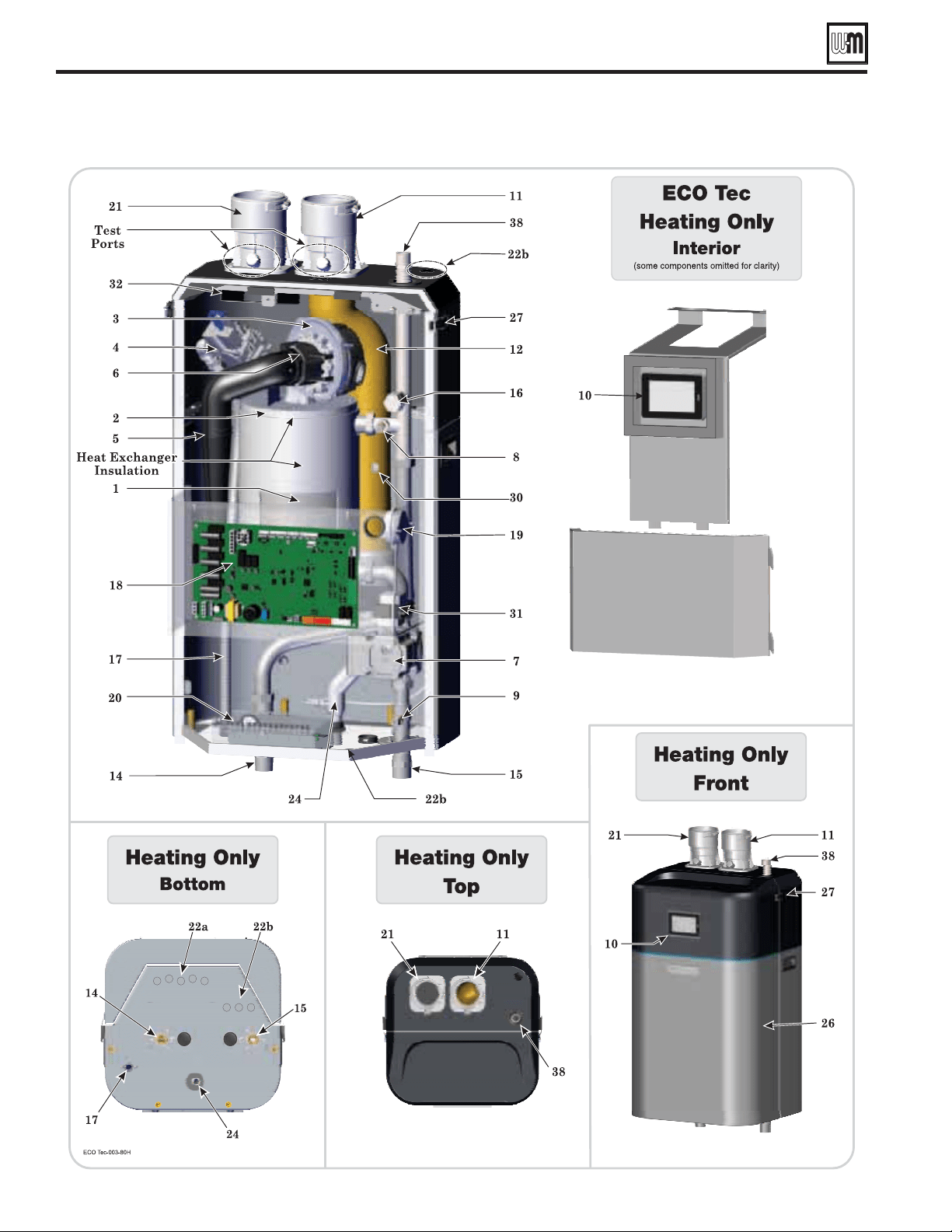
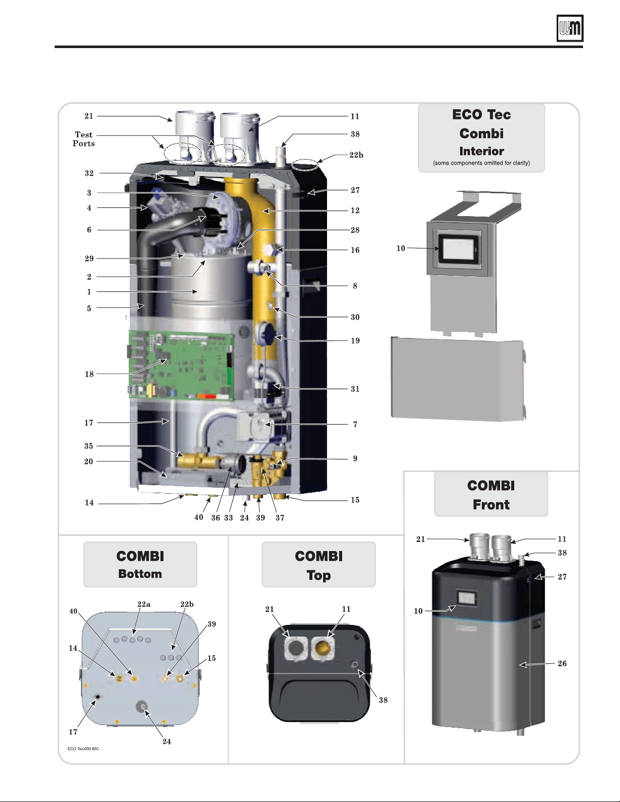
The corr
osion resistant fire tube heat exchanger is our method of
transferring heat from the combustion chamber to the water.
Note !
: Combi shows cover plate (Item 2) (insulation removed for clarity),
Heating Only has insulation covering shown.
The advanced blower design and air inlet silencer on ECO
Tec boilers
results in very quiet operation. Air enters the boiler enclosure through
the air intake adapter (Item 21), flows through the enclosure, enters
the air inlet silencer (Item 5), then enters the venturi (Item 6) where it
mixes with gas before entering the blower. The blower pulls air through
these components and then pushes it through the cover plate
(Item 2)
to the burner (Item 13- not shown).
The automatic gas valve references the pressure in the cabinet and
allows gas to flow when the control (Item 18) applies power. (An on/
off switch is attached to the gas valve. It allows the shutting off of the
gas supply for servicing or shut down).
The horn-shaped air inlet silencer significantly reduces fan noise,
providing exceptionally quiet operation.
When air flows through the venturi, a negative pressure is created.
This causes gas to flow from the gas valve into the venturi, where it is
mixed with the air. The gas/air mixture then continues into the blower.
The pump is used to circulate hot water from the boiler, and then pass
it into heating system or the brazed plate heat exchanger.
This dual sensor monitors boiler outlet water temperature. The control
adjusts boiler firing rate so the outlet water temperature is correct,
based on the calculated (if outdoor reset used — see page 149) or
fixed target temperature.
This sensor monitors boiler in water temperature. The Control may
reduce boiler input depending on if the boiler in and boiler out water
temperature difference is too large
.
The electronic color touch screen display is used to configure boiler
settings and monitor boiler operation. This display allows changing
display mode, selecting and adjusting control settings, and resetting
the control after lockout.
Internal flue pipe that carries exhaust gasses from heat exchanger to
vent/flue adapter.
Made with high-grade stainless steel construction, the burner uses pre-
mixed air and gas. The burner and control provide modulating firing.
3/4
This plug can be removed to install a low water cut-off (LWCO).
This stainless steel flexible gas line connects the incoming gas line to the
gas valve.
The gas line has a ½” Male NPT connection for installation.
Air pressure switch monitors maximum flue pressure.
120VAC field wiring connections.
The bottom middle knockouts are designated for line voltage wiring
only. Ensure all wiring entrances are sealed.
22
The bottom right side and top right knockouts are designated for
low voltage wiring only. Ensure all wiring entrances are sealed.
Shipped loose for field piping. Pipe drain valve on reducing tee at the
lowest point of return piping to boiler. See instructions, page 13 in
this manual.
The outlet at the bottom of the boiler to drain condensate. The
condensate trap assembly attaches here.
The condensate trap assembly is field-installed, condensate drain trap
is connected to the condensate tube (Item 24) as shown in this manual.
The jacket door is sealed to the boiler assembly around its entire
perimeter.
Two (2) latches secure the door in place.
The burner flame is ignited by applying a high voltage to the ignition
electrode. This causes a spark (from electrode to ground). After
ignition, the electrode measures flame signal.
The quartz glass window provides a view of the burner surface and
the flame.
This dual sensor monitors the flue gas exit temperature. The control
will shut down the boiler if flue gas temperature gets too hot.
This protects the flue pipe and the heat exchanger from overheating.
The 120V/24V transformer provides 24V to low voltage control
circuitry. Do NOT splice wiring into transformer.
The air baffle protects internal boiler components by diverting any
incoming moisture or debris away from critical components.
This secondary heat exchanger allows heat to transfer from the boiler
to the domestic water.
This sensor monitors domestic hot water leaving the brazed plate. The
control reduces or increase boiler input, depending on how close the
water is to target set point.
This valve will change boiler water flow either through the brazed plate
or bypass the braze plate and out to the heating system.
This valve will change boiler water flow either through the brazed plate
or bypass the braze plate and out to the heating system.
This sensor monitors the DHW (domestic hot water) flow rate. When
flows 0.5 GPM or greater are detected, the boiler control will allow the
boiler to turn on and modulate accordingly.
Use 3/4" tee and 3/4" street elbow to connect relief valve. It is
recommended to connect an automatic air vent to top tee connection.
3/4
3/4
The ECO
Tec
Gas-fired water boilers
Part number 550-100-260/0520
4
ECO
®
Tec
GAS-FIRED WATER BOILER – 80/110/150/199 BOILER MANUAL
The ECO
Tec Heating Only Gas-fired water boilers
(ECO
Tec 80 model shown below)
Part number 550-100-260/0520
5
ECO
®
Tec
GAS-FIRED WATER BOILER – 80/110/150/199 BOILER MANUAL
The ECO
Tec Combi Gas-fired water boilers
(ECO
Tec 80 model shown below)
Part number 550-100-260/0520
6
ECO
®
Tec
GAS-FIRED WATER BOILER – 80/110/150/199 BOILER MANUAL
Failure to adhere to the guidelines below can result in severe personal injury, death or substantial property damage.
Relieve pressure from the system
before isolating the expansion tank.
To avoid electric shock, disconnect all
electrical supplies to the boiler before
performing maintenance.
To avoid severe burns, allow boiler to cool
before performing maintenance.
This boiler contains ceramic fiber
and fiberglass materials. Refer to the
WARNING and instructions on page 106.
Do not block flow of combustion or
ventilation air to boiler.
Should overheating occur or gas supply
fail to shut off, do not turn off or
disconnect electrical supply to circulator.
Instead, shut off the gas supply at a
location external to the appliance.
DO NOT install combustion air intake
where there is a risk of combustion air
contamination.
A carbon monoxide detector that is
wired on the same electrical circuit as
the boiler is strongly recommended.
Provide surge protection in the boiler
power supply. This will reduce the
possibility of damage to the boiler
control.
The
ECO
Tec heat exchanger is made of
stainless steel, and requires that system
water chemistry be within the limits in
this manual.
. See
page 97 for details.
Thoroughly flush the system (
connecting boiler) to remove sediment.
The high-efficiency heat exchanger can
be damaged by build-up or corrosion
due to sediment.
Do not use petroleum-based cleaning
or sealing compounds in boiler system.
Gaskets and seals in the system may be
damaged. This can result in substantial
property damage.
Continual fresh make-up water will
reduce boiler life. Mineral buildup in
eat exchanger reduces heat transfer,
overheats the stainless steel heat
exchanger, and causes failure. Addition
of oxygen carried in by make-up water
can cause internal corrosion. Leaks in
boiler or piping must be repaired at once
to prevent make-up water. Use this boiler
ONLY in a closed-loop system.
Do not add cold water to a hot boiler.
Thermal shock can cause the heat
exchanger to crack.
NEVER use automotive or standard
glycol antifreeze. Use only freeze-
protection fluids made for hydronic
systems. Follow all guidelines given by
the antifreeze manufacturer. Thoroughly
clean and flush any replacement boiler
system that has used glycol before
installing the new boiler. Use only the
products listed by Weil-McLain for use
with this boiler. See page 98 for details.
Frozen Water Damage
Hazard
Residences or buildings that are unattended
in severely cold weather, boiler system
components failures, power outages,
or other electrical system failures could
result in frozen plumbing and water
damage in a matter of hours. For your
protection, take preventative actions such
as having a security system installed that
operates during power outages, senses
low temperature, and initiates an effective
action. Consult with your boiler contractor
or a home security agency.
If any part of a boiler, burner or its controls has
been sprayed with or submerged under water,
either partially or fully, DO NOT attempt to operate
the boiler until the boiler has been either replaced
or completely repaired, inspected, and you are
sure that the boiler and all components are in
good condition and fully reliable.
Otherwise, by operating this boiler, you will
cause a fire or explosion hazard, and an electrical
shock hazard, leading to serious injury, death, or
substantial property damage. See the instructions
at right.
— The exposure of boiler components to
saltwater can have both immediate and long-term effects. While
the immediate effects of saltwater damage are similar to those of
freshwater (shorting out of electrical components, washing out
of critical lubricants, etc.), the salt and other contaminants left
behind can lead to longer term issues after the water is gone due to
the conductive and corrosive nature of the salt residue. Therefore,
Weil-McLain equipment contaminated with saltwater or polluted
water will no longer be covered under warranty and should be replaced.
— If any or came
into contact with water, or was suspected to have come into contact
with water, replace the boiler with a new Weil-McLain boiler.
Commonwealth of
Massachusetts
When the boiler is installed within the Commonwealth of Massachusetts:
This product must be installed by a licensed plumber or gas fitter.
If antifreeze is used, a reduced pressure back-flow preventer device shall be used.
Sidewall vent air installations — see instruction on page 24.
— Read all instructions, including this manual
and all other information shipped with the boiler,
before installing. Perform steps in the order given.
— This manual is for use only by a qualified
heating installer/service technician. Refer to User’s
Information Manual for your reference.
— Have this boiler serviced/inspected by a qualified
service technician, at least annually.
Failure to comply with the above could result in severe
personal injury, death or substantial property damage.
Write in the Consumer Protection (CP) number in the
space provided on the Installation certificate on page 151
if not already shown.
When calling or writing about the boiler— Please have
the boiler model number from the boiler rating label
and the CP number from the boiler jacket.
Consider piping and installation when determining
boiler location.
Any claims for damage or shortage in shipment must be
filed immediately against the transportation company
by the consignee.
Please read before proceeding

Part number 550-100-260/0520
7
ECO
®
Tec
GAS-FIRED WATER BOILER – 80/110/150/199 BOILER MANUAL
Installations must comply with:
Local, state, provincial, and national codes, laws,
regulations and ordinances.
National Fuel Gas Code, ANSI Z223.1/NFPA 54 – latest
edition.
National Electrical Code ANSI/NFPA 70 – latest edition.
Electrical installation and grounding must be in
accordance with CSA C22.1, Part 1, Canadian Electrical
Code, and/or local codes.
For Canada only: CAN/CSA B149.1, Natural Gas and
Propane Installation Code, and any local codes.
Where required by the authority having jurisdiction, the
installation must conform to the Standard for Controls
and Safety Devices for Automatically Fired Boilers,
ANSI/ASME CSD-1.
The boiler gas manifold and controls met
safe lighting and other performance criteria
when boiler underwent tests specified in
ANSI Z21.13 – latest edition.
Before locating the boiler, check:
1. The boiler
can be floor-standing with optional kit or
wall mounted.
2. Wall construction — If the boiler is wall-mounted,
make sure the wall construction is suitable to carry
the weight of the boiler and components. See page 10
for instructions.
3. The boiler is suitable for INDOOR installation only.
4. Check for nearby connection to:
Condensate drain
5. Check area around boiler. Remove any combustible
materials, gasoline and other flammable liquids.
Failure to keep boiler area clear and free of
combustible materials, gasoline and other
flammable liquids and vapors can result in
severe personal injury, death or substantial
property damage.
6. The boiler must be installed so that gas control system
components are protected from dripping or spraying
water or rain during operation or service.
7. If new boiler will replace existing boiler, check for and
correct system problems, such as:
Sediment or corrosion in system piping — clean
and flush piping BEFORE connecting the new
boiler. See page 97.
System leaks causing oxygen corrosion or heat ex-
changer cracks from hard water deposits.
Incorrectly-sized expansion tank.
Lack of freeze protection in boiler water causing
system and boiler to freeze and leak.
Residential garage installation
Take the following special precautions when installing the boiler in a residential
garage. If the boiler is located in a residential garage:
Mount the boiler with its burner and igniter are at least 18 inches above
the floor. Follow the National Fuel Gas Code, ANSI Z223.1 for U. S.
installations, or Natural Gas and Propane Installation Code, CSA B149.1
and B149.2 for Canadian installations.
Locate or protect the boiler so it cannot be damaged by a moving vehicle.
Ensure that the installation complies with all applicable codes.
Prevent boiler water and condensate from freezing.
Combustion air requirements
The ECO
Tec boiler is certified as a=- Direct Vent appliance. It can be converted
to Direct Exhaust by using the Approved Weil-McLain Direct Exhaust kit.
Direct vent (sealed combustion) where combustion air is ducted from
outdoors.
Direct exhaust where combustion air is obtained directly from the
boiler room.
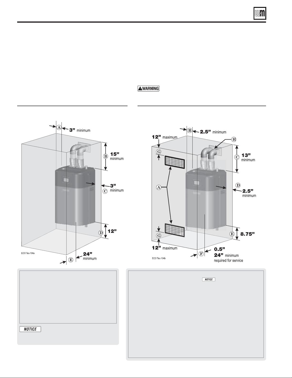
Provide air openings to room
ECO
Tec
1. No air ventilation openings into boiler room are needed if Direct vent and
clearances around boiler are at least equal to the SERVICE clearances shown
in Figure 1, page 8.
2. For spaces that DO NOT supply the minimum service clearances, provide
two openings as shown in Figure 2, page 8. Each opening must provide
1 square inch free area per 1,000 Btuh of boiler input.
The space must be provided with combustion/
ventilation air openings correctly sized for all
appliances located in the same space as the
ECO
Tec boiler.
Reinstall boiler jacket door after servicing. The boiler
jacket door must be securely fastened to the boiler to
prevent boiler from drawing air from inside the boiler
room. This is particularly important if the boiler is
located in the same room as other appliances.
Failure to comply with the above warnings could result in
severe personal injury, death or substantial property damage.
ECO
Tec
Follow the sizing requirements shown in Figure 29, page 26.
Vent and air piping
1. The boiler requires a special vent system, designed for pressurized
venting. The boilers are rated ANSI Z21.13 Category IV (pressurized vent,
likely to condense in the vent). See instructions beginning on page 20.
2. You must also install air piping from outdoors to the boiler air intake
adapter. The resultant installation is categorized as direct vent (sealed
combustion). Note prevention of combustion air contamination on page 20
when considering vent/air termination.
3. Direct exhaust venting can be done with the approved Weil-McLain Direct
Exhaust Kit, please see page 137 for kit information
4. Vent and air must terminate near one another unless otherwise specified in
this manual. Vent and air piping may be routed vertically through the roof
or out a side wall, following the options given in this manual. You may use
any of the vent/air piping methods covered in this manual. Do not attempt
to install the boiler using any other means.
5. Be sure to locate the boiler such that the vent and air piping can be routed
through the building and properly terminated. The vent/air piping lengths,
routing and termination method must all comply with the methods and
limits in instructions beginning on page 20.
Boiler location
Part number 550-100-260/0520
8
ECO
®
Tec
GAS-FIRED WATER BOILER – 80/110/150/199 BOILER MANUAL
A. Provide combustion air/ventilation openings per Figure 29, page 26 or as otherwise
directed in this manual or by applicable codes.
If the installation does not
provide the minimum clearances in Figure 1, then the enclosure MUST HAVE air
openings located per Figure 2, above. Each of these air openings must have free area of at
least 1 square inch per 1,000 MBH of boiler input.
B. Left side clearance to combustibles =2.5 inches minimum.
C. Top of boiler clearance to combustibles = 13.00 inches minimum.
D. Right side clearance to combustibles = 2.5 inches minimum.
E. Bottom of boiler clearance to combustibles = 8.75 inches minimum (must be 18 inches
above floor for garage installations) for wall hung installation, 0 inches minimum for
floor standing installation.
F. Clearance in front of the boiler = 0.5 inches, but 24 inches minimum required for
service.
G. Air openings must be located in the FRONT of the enclosure, as shown. They must be no
more than 12 inches from the floor or ceiling, as shown.
H. Vent pipe must be minimum 3/16 inch from combustibles. Opening in combustible
wall, floor, ceiling or roof must be 3/8 inches larger than flue pipe diameter, fitted with
corrosion resistant steel thimble, or larger if required by codes or as specified by vent
pipe manufacturer.
A. Left side service clearance = 3 inches minimum.
B. Service clearance above top of boiler = 15 inches
minimum.
C. Right side service clearance = 3 inches minimum.
D. Service clearance below the boiler = 12 inches minimum
for wall hung installation, 0 inches minimum for floor
standing installation.
E. Service clearance in front of the boiler = 24 inches
minimum.
ADDITIONAL service clearance may
be needed, depending on how piping
is routed to the boiler.
Provide clearances for service
access — RECOMMENDED
1. See Figure 1 for recommended service clearances.
2. If you do not provide minimum service clearances
shown, it might not be possible to service the boiler
without removing it from the space.
.
Provide clearances from combustible
materials — REQUIRED
1. See Figure 2 for REQUIRED minimum clearances. ALL
installation must provide at least these minimums.
2. Hot water pipes — at least ½ inches from combustible materials.
3. Vent pipe — at least 3/16 inches from combustible materials.
4. See Figure 1 for service clearance minimums.
.
Boiler location (continued)
REQUIRED minimum clearances
()
RECOMMENDED service clearances
()
Part number 550-100-260/0520
9
ECO
®
Tec
GAS-FIRED WATER BOILER – 80/110/150/199 BOILER MANUAL
Flooring and foundation
()
Flooring
With the optional floor standing pedestal kit, the boiler is
approved for installation on combustible flooring, but must never
be installed on carpeting.
Do not install boiler on carpeting even if foundation
is used. Fire can result, causing severe personal
injury, death or substantial property damage.
Foundation
1. Provide a solid foundation pad, at least 2 inches above the
floor, if any of the following is true:
floor can become flooded,
the floor is dirt, sand, gravel or other loose material,
the boiler mounting area is severely uneven or sloped.
2. The minimum foundation size is:
ECO
Tec: 20 inches wide x 20 inches deep.
3. Foundation may be of wood, brick or concrete (minimum 2
inches thick) construction.
If flooding is possible, elevate boiler sufficiently to prevent
water from reaching boiler.
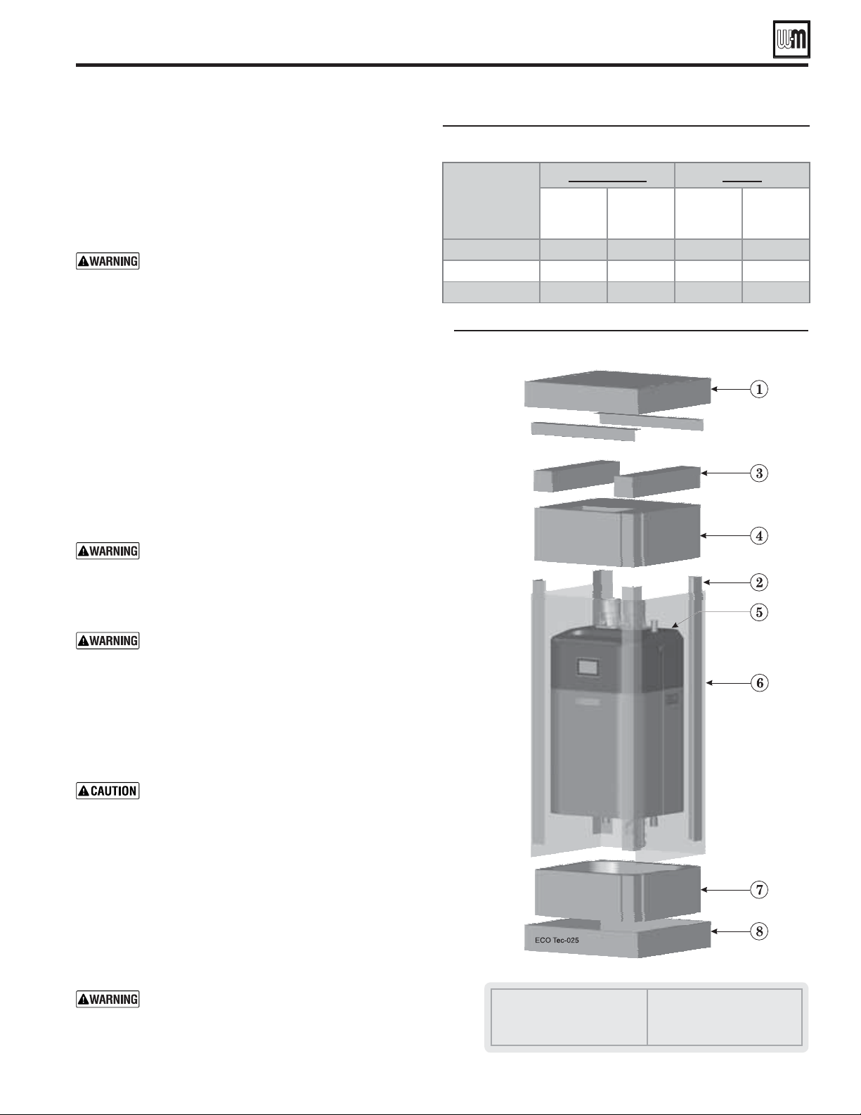
Remove boiler from crate
. Use caution not to drop
the boiler or cause bodily injury while lifting
and handling. Verify that the boiler is securely
attached to prevent possibility of boiler falling after
installation.
After the boiler is removed from the shipping
carton, allow the boiler to sit on its
bottom. This would cause pressure on protruding
plastic, resulting in interior damage. Either lay
the boiler on its back or leave on the styrofoam
protective shipping base.
Do not drop boiler or bump jacket on floor or pallet.
Damage to boiler can result.
Cold weather handling — If boiler has been
stored in a very cold location (below 0°F) before
installation, handle with care until the plastic
components come to room temperature.
1. The ECO
Tec boiler is generally easier to handle and
maneuver after removing the shipping container.
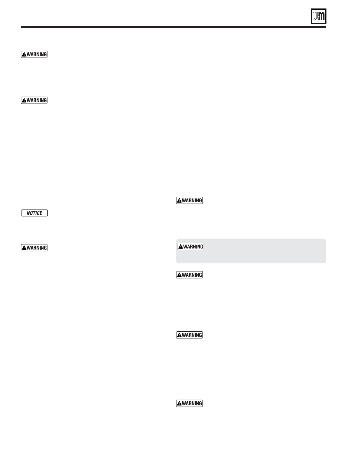
2. Remove Items 1, 2, 3, 4, and 6 in Figure 3. Remove trim kit
and parts from Item 4.
3.
(Item 7) and bottom cardboard cap (Item 8), until
ready to place on the wall. If removing the boiler from the
shipping base, rest the boiler on its back, NOT on its bottom.
Failure to comply with the procedure given could
result in severe personal injury, death or substantial
property damage.
Cardboard cap, top
Cardboard angles
Pad
Styrofoam protective cap
Boiler
Cardboard sleeve
Styrofoam protective base
Cardboard cap, bottom
Prepare boiler location
Boiler shipping container
ECO Tec
Boiler
Model
Heating Only Combi
Without
Pedestal
lbs.
With
Pedestal
lbs.
Without
Pedestal
lbs.
With
Pedestal
lbs.
80/110 141 163 152 174
150 162 184 172 194
199 178 200 187 209
Boiler operating weights
Wall-mount bracket and studs
Part number 550-100-260/0520
10
ECO
®
Tec
GAS-FIRED WATER BOILER – 80/110/150/199 BOILER MANUAL
Place boiler on wall-mount bracket
6. Remove the mounting bracket and drill holes 1/4"
diameter by 3 inches deep, centered on the screw slot
outlines. (For metal stud walls, drill required clearance
holes.)
7. Position the wall-mount bracket on the wall. Insert
and loosely tighten the two (2) lag screws (or toggle
bolts for metal studs).
8. Level the wall-mounting bracket. Then tighten
lag screws securely. For drywall or plaster lathe
installations, avoid tightening so much that the bracket
digs into the wall surface.
9. Once bracket is installed and leveled it is recommended
to install additional screws in center holes to fully
secure to mounting surface.
Place boiler on bracket
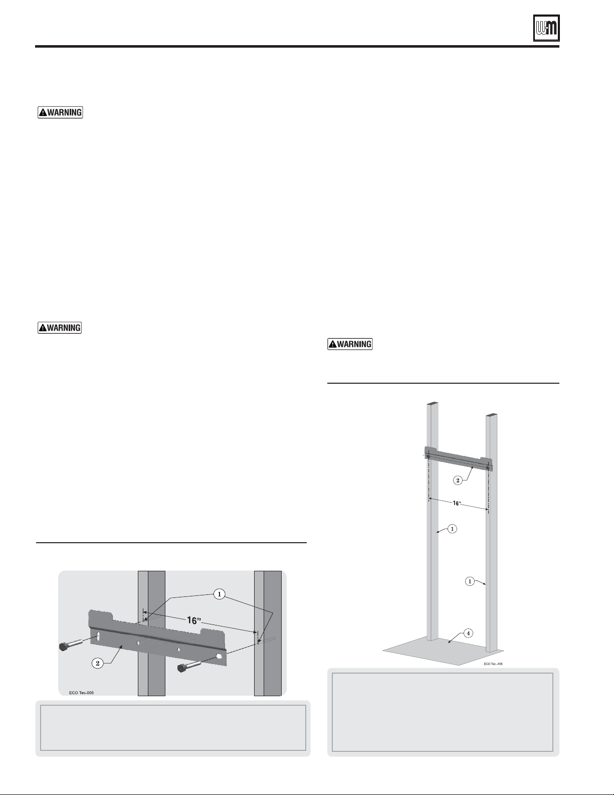
1. See Figure 5. The wall-mount bracket must be installed
before mounting the boiler.
2. Measure 17 1/2 inches below the bottom edge of the
wall-mount bracket (Item 2). Strike a line or place a
piece of masking tape with its top edge even with the
17
1/2-inch mark. (This line, or tape, will indicate
whether the boiler has been properly seated onto the
wall-mount bracket.)
, and requires two
people to lift and place. Wear non-slip
leather gloves to prevent possibility of cuts
from sheet metal edges.
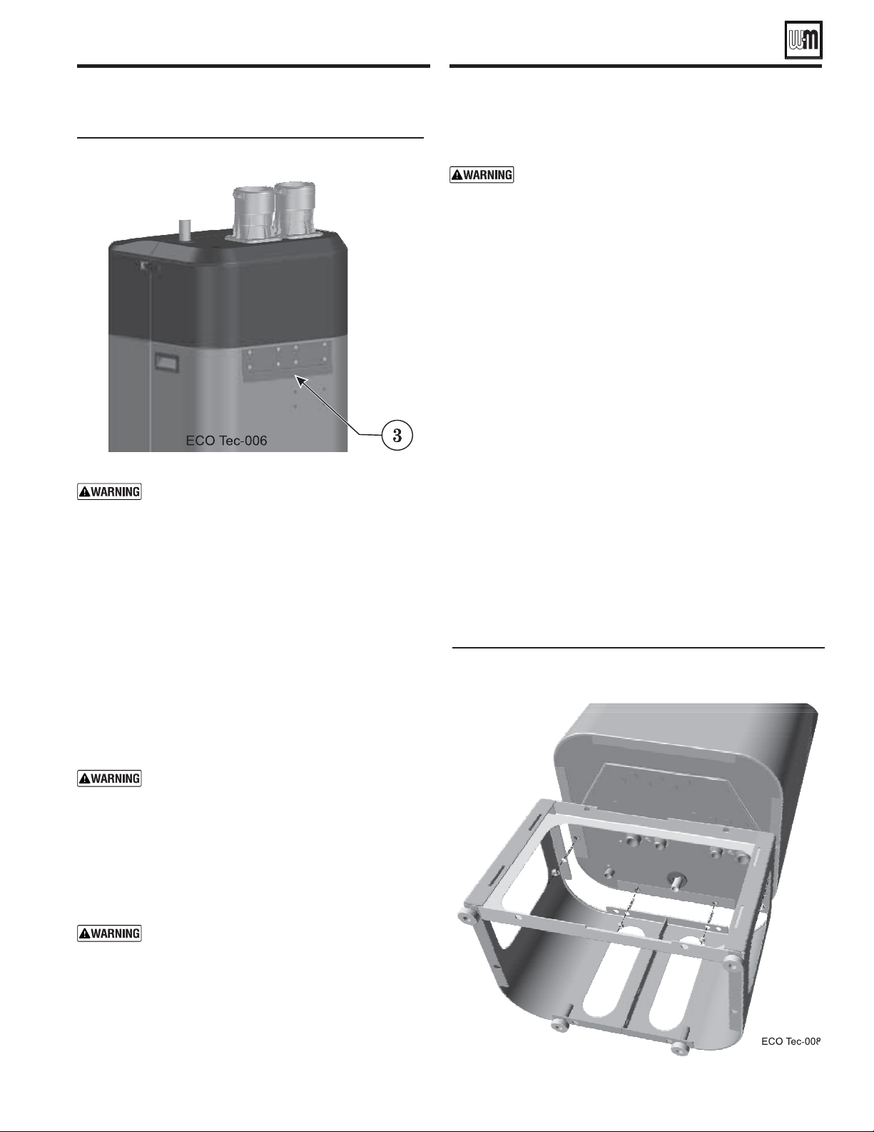
1 Studs — Pre-drill through the wall into the studs ¼ inch diameter x 3
inches deep — Studs must be on 16-inch centers. If studs are any other
spacing, provide a secure, solid mounting surface on which to attach
the boiler wall-mounting bracket.
2 Wall-mount bracket — secure wall mount bracket to wall as instructed
on previous page.
3 Boiler mounting bracket (Figure 6 back of boiler)
4 Floor surface
1 Studs — Pre-drill through the wall into the studs ¼ inch diameter x 3 inches deep for
3/8-inch lag screws— Studs must be on 16-inch centers. If studs are any other spacing,
provide a secure, solid mounting surface on which to attach the boiler wall-mounting bracket.
2 Wall-mount bracket
Wall-mounting the boiler
Wall-mounting requirements
DO NOT attempt to attach the wall mount bracket using
anchors or any means other than directly securing to the
wall studs (or equivalent wood structure if studs are not
on 16-inch centers).
.
1. This boiler includes a wall template to aid in installation, unfold the
template and place it against the wall to aid in locating mounting
holes and ensuring proper clearance.
2. Stud spacing: Bracket holes are spaced for studs on 16-inch centers.
For other stud spacing, provide secure, solid mounting surface on
which to attach the boiler wall-mounting bracket.
3. Wood stud wall: Install bracket with lag screws (3/8" x 3") included
in kit, only into the studs.
4. Metal stud wall: Secure bracket and spacer board to studs with
the appropriate size bolts and washers that can handle the boiler's
operating weight listed on page 9 and any additional weight from
venting and gas/water piping to be determined by contractor /
installer (hardware not included with kit).
Verify that the studs are suitable for carrying a wall-mounted
load. Some metal studs are not designed for this purpose.
5. If the mounting wall has exposed studs, installer must provide a
backer board to mount boiler. Boiler cannot be leveled without a
backing surface.
6. Mount the boiler on the wall following these instructions. The
boiler mounting bracket must engage with the wall-mount bracket.
Make sure the bracket is not just resting on the edge of the boiler
mounting bracket. Perform all procedures given in the Boiler
Manual on previous pages before mounting the boiler.
Install the wall-mount bracket (by installer)
1. See Figure 4.
2. Locate the studs — must be on 16-inch centers. See previous
page instructions if studs are not on 16-inch centers.
3. Place the wall-mount bracket (Figure 4, Item 2) on the wall, using
a level to align correctly.
4. Place the wall-mount bracket so the mounting slots are centered
over the studs.
5. Level the bracket and trace the outline of the screw slots with a pencil.
Part number 550-100-260/0520
11
ECO
®
Tec
GAS-FIRED WATER BOILER – 80/110/150/199 BOILER MANUAL
Pedestal floor stand assemblyWall-mounting the boiler
(continued)
Pedestal floor stand
()
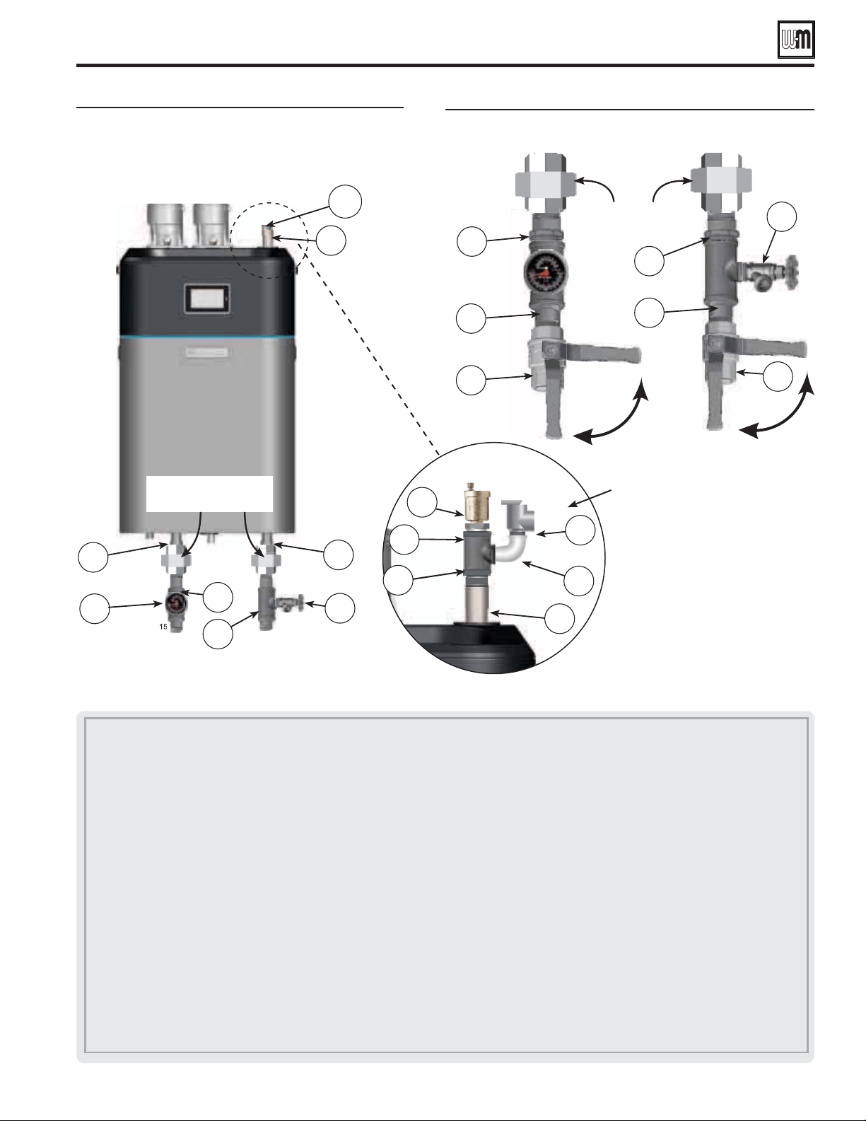
1. Carefully remove boiler from the styrofoam protective base and
set on back. Remove door from front of boiler by unfastening
latches on side of cabinet.
2. Remove four (4) 5/16” studs from floor stand hardware trim
bag. Install studs by hand in rivet nuts on bottom of boiler.
See Figure 7.
3. Remove front access panel from pedestal assembly by sliding
it up.
4. Align holes in top of pedestal with studs on bottom of boiler.
Slide stand over studs. Remove 5/16” nuts from trim bag.
Install nuts on studs using ½” socket or wrench. Make sure
to align sides of pedestal with cabinet before tightening down
nuts. Do not overtighten.
5. Install the condensate trap assembly following instructions
on page 56
6. After confirming nuts are tightened, obtain assistance and lift
the boiler into upright position.
7. Set boiler in place and level by adjusting leveling legs with
flat head screwdriver.
Boiler mounting bracket
Pedestal floor stand assembly (front access
panel removed)
The jacket door can be left in place when
handling the boiler, but the boiler must ONLY
be lifted by the bottom and rear of the sheet
metal housing — NOT by any pipe or plastic
part.
3. .
4. Lift the boiler high enough that its mounting bracket
(Figure 6, Item 3) will be above the wall-mount bracket
(Figure 5, page 10, Item 2).
5. Let the rear of the boiler slide against the wall bracket as
you lower the boiler into place.
6. Adjust the boiler properly until engaged with the wall
bracket and the boiler slips into the correct position.
7. When the brackets are engaged correctly, the bottom of
the boiler enclosure will be at or near the pencil line, or
tape, you applied in step 2.
When mounting the boiler, use the method
described on step 2, page 10 to ensure the
boiler bracket and the wall bracket are properly
engaged. If not, the boiler could fall. Failure to
comply could result in severe personal injury,
death or substantial property damage.
8. Ensure boiler is level front-to-back.
Ensure boiler is NOT pitched downward
with the front of the boiler lower than
the back of the boiler. This can prevent
condensate from draining properly. Failure
to comply could result in severe personal
injury, death or substantial property damage.
Part number 550-100-260/0520
12
ECO
®
Tec
GAS-FIRED WATER BOILER – 80/110/150/199 BOILER MANUAL
. This is the maximum
allowable relief valve setting for the boiler. Failure
to comply could prevent the relief valve from
operating as needed, resulting in possibility of
severe personal injury, death or substantial property
damage.
. Failure to prevent the
boiler pipes from turning could damage pipes or
heat exchanger, resulting in possible severe personal
injury, death or substantial property damage.
Hydrostatic pressure test
Pressure test the boiler before permanently attaching water or
gas piping or electrical supply.
Install pipe fittings for relief valve and
P/T gauge
1. Install the reducer bushings (150/199), reducing tees, and
close nipples, shipped loose with the boiler, located and
oriented as shown in Figure 8, page 13.
Boilers installed in locations with less than the
RECOMMENDED service clearances will need to
adjust piping layout to meet space requirements.
2. Apply pipe dope to all fittings sparingly.
. Temporarily install a ¾"
pipe cap in the boiler top outlet pipe location as
directed in these instructions. The cap must be
removed after the test.
Failure to comply with the above could prevent
the relief valve from operating as needed, resulting
in possibility of severe personal injury, death or
substantial property damage.
3. Install the pressure/temperature gauge to the reducing tee as
shown in Figure 8, page 13.
Install fittings and valves required for
hydrostatic testing
1. The following piping components (supplied by installer) are
required for the test configuration:
a. Two shut-off valves (1" NPT on 80/110,
1¼" NPT on 150/199).
b. Two close nipples (1" NPT on 80/110,
1¼" NPT on 150/199).
c. ¾" NPT pipe cap.
2.
install a ¾" NPT pipe cap on the
boiler
top outlet pipe. After the hydrostatic test, this cap must be
removed and the relief valve, tee and elbow must be installed.
Fill and pressure test
1. See Figure 9, page 13 for use with the following instructions.
2. CLOSE the boiler drain valve (Item 11). Connect a hose to
fresh water supply and to the drain valve.
3. Place a bucket under the ends of the isolation valves (Item 9
and 10) to catch water drippings.
4. CLOSE isolation valve Item 10, then crack open the 3/4" cap
(Item 3a) slightly. Leave isolation valve Item 9 open.
5. Slowly open the boiler drain valve (Item 11) and fresh water
supply to fill boiler with water. The boiler and piping will fill
quickly because of the low water content.
6. When water begins to seep from 3/4" cap (Item 3a), tighten
the cap.
7. Continue filling until water flows from supply isolation valve
(Item 9), then close the valve.
8. The test pressure should be 1-1/2 times the pressure setting
of the relief valve to be installed on the boiler (45 psig for a
30-psig relief valve; 75 psig for a 50-psig relief valve). Open
boiler drain valve until desired pressure is achieved.
9. Hold at test pressure for 10 minutes.
Do not leave boiler unattended. A cold water fill
could expand and cause excessive pressure, resulting
in severe personal injury, death or substantial
property damage.
10. Make sure constant gauge pressure has been maintained
throughout test. Check for leaks. Repair if found.
Failure to
do so can damage boiler, resulting in substantial
property damage.
Do not use petroleum-based cleaning or sealing
compounds in boiler system. Gaskets and seals
in the system may be damaged. This can result in
substantial property damage.
Drain and remove fittings
1. Disconnect fill water hose from water source.
2. Drain boiler through drain valve (Item 11).
Use caution when releasing pressure from the boiler.
Rapid water flow could cause injury.
3. Remove hose after draining.
4. Remove nipples and valves unless they will remain for use in
the system piping.
5. Remove cap and install relief valve, tee and elbow as specified
in the following WARNING.
6. If any internal leaks occurred, make sure all water has been
cleaned up and electronic components, including the boiler
control, is completely dry.
Remove cap from Air Elimination/Relief Valve
Connection Water Pipe (1a). Install the relief valve
in the ¾" elbow. See page 48 or page 51 to install
relief valve discharge piping. Failure to install the
boiler relief valve could result in severe personal
injury, death or substantial property damage.
Boiler hydrostatic test
Part number 550-100-260/0520
13
ECO
®
Tec
GAS-FIRED WATER BOILER – 80/110/150/199 BOILER MANUAL
1 Boiler Out (Supply) connection, (male, 1" NPT )
1a Air Elimination/Relief Valve Connection Water Pipe, (male, 3/4" NPT) use for relief vale and air elimination.
2 Boiler In (Return) connection, (male, 1" NPT ).
3 Boiler relief valve, shipped loose with boiler — .
3a Install a ¾" NPT cap in the Air Elimination/Relief Valve Connection Water Pipe.
.
4 Pressure/temperature gauge, shipped loose with boiler.
5a Reducing tee, NPT, 1 " x 1 " x ¼" on 80/110, & 1 ¼" x 1 ¼" x ¼" on 150/199, shipped loose with boiler.
5b Reducing tee, NPT, 1 " x 1 " x ¾" on 80/110, & 1 ¼" x 1 ¼" x ¾" on 150/199, shipped loose with boiler.
7 Bushing, NPT, 1 ¼" x 1", shipped loose with boiler (150/199 only).
8 Nipple, NPT 1" x close on 80/110, & 1 ¼" x close on 150/199, by installer .
9 Isolation valve on supply connection, by installer (1" NPT on 80/110, 1¼" NPT on 150/199).
10 Isolation valve on return connection, by installer (1" NPT on 80/110, 1¼" NPT on 150/199).
11 ¾" NPT boiler drain valve, shipped loose with boiler — after hydrostatic testing, move drain valve to lowest point on the return piping if not
already there.
12 Auto air vent, by installer.
13 Bushing, NPT 3/4", by installer.
14 Tee, NPT 3/4" x 3/4" x 3/4", shipped loose with boiler.
15 Street elbow, NPT 3/4" x 3/4", shipped loose with boiler.
Boiler hydrostatic test (continued)
Install pipe fi ttings for relief valve and
pressure/temperature gauge —
(see legend below)
Install piping components required for
hydrostatic test (see legend below)
(&27HF
Boiler In
Boiler Out
1
4
5a
Recommended but
not included
3a
2
11
1a
(&27HFD
(150/199 only)
Recommended but
not included
8
8
11
9
10
7
7
(150/199 only)
5b
(&27HF
1a
3
15
14
12
13
Recommended piping after
hydrostatic test
Part number 550-100-260/0520
14
ECO
®
Tec
GAS-FIRED WATER BOILER – 80/110/150/199 BOILER MANUAL
Gas conversions
Prepare boiler for propane —
ECO
Tec 80/110/150/199
(if required)
Propane operation
.
— For a boiler already
installed, you must turn off gas supply, turn
off power and allow boiler to cool before
proceeding. You must also completely test
the boiler after conversion to adjust gas valve
to proper setting, verify performance, and
start up the boiler following instructions
beginning on page 102 of this manual.
— See
Figure 10, page 15 LP gas venturi will have a
black label and will be clearly labeled “LP”.
Must change control settings to proper gas
type.
Failure to comply could result in severe
personal injury, death or substantial property
damage.
This conversion kit shall be installed by a
qualified service agency in accordance with the
manufacturer’s instructions and all applicable
codes and requirements of the authority
having jurisdiction. If the information in these
instructions are not followed exactly, a fire, an
explosion or production of carbon monoxide
may result causing property damage, personal
injury or loss of life. The qualified service agency
is responsible for the proper installation of this
kit. The installation is not proper and complete
until the operation of the converted appliance
is checked as specified in the manufacturer’s
instructions.
Natural Gas to Liquefied Petroleum (Propane)
conversion kits
ECO
TecP/N 510-811-415 NG to Propane Gas Conversion Kit contents:
511-050-233 1
562-150-304 3
1
1
1
550-225-336 1
1
1
ECO TecP/N 510-811-416 NG to Propane Gas Conversion Kit contents:
511-050-234 1
562-150-304 3
1
1
1
550-225-336 1
1
1
ECO Tec
511-050-235 1
562-150-304 3
1
1
1
550-225-336 1
1
1
Follow all instructions in proper order.
Do not tamper with venturi. DO NOT change or modify
venturi in any way.
Dispose of an uninstalled venturi; do not leave in the
building.
Caution – the gas supply shall be shut off prior to
disconnecting the electrical power, before proceeding
with the conversion.
Whenever the venturi is removed, all gaskets must be
replaced with new gaskets.
Contact gas supplier to size pipes, tanks and 100% lockup gas
pressure regulator.
1. Adjust propane supply regulator provided by gas supplier
between the pressure listed below:
2. Pressure required at gas valve inlet pressure port:
a. Maximum: 14” (356 mm) w.c. with no flow (lockup).
b. Minimum gas pressure, with gas flowing (verify during
boiler startup, while boiler is at high fire): 3½” (89 mm) w.c.

Part number 550-100-260/0520
15
ECO
®
Tec
GAS-FIRED WATER BOILER – 80/110/150/199 BOILER MANUAL
Liquefied Petroleum (Propane) to Natural Gas
conversion kits
ECO Tec
511-050-230 1
562-150-304 3
1
1
1
550-225-336 1
1
ECO Tec
511-050-231 1
562-150-304 3
1
1
1
550-225-336 1
1
ECO Tec
511-050-232 1
562-150-304 3
1
1
1
550-225-336 1
1
Propane gas venturi label identification
(Black label)
Natural gas venturi label identification
(White label)
Installing propane venturi —
1. Propane venturi will have a black label identifying venturi
part number. See Figure 10 for correct part number.
2. Verify that the label on the propane venturi is correct for
the model size (see Figure 10 below).
3. Shut off the gas supply prior to disconnecting the electrical
power, before proceeding with the conversion.
4. If the jacket front door was not already removed, remove it.
5. Locate the blower and venturi (see Figure 12).
80/110
511-050-233 LPG 20
150 511-050-234 LPG 26
199 511-050-235 LPG 28
80/110
511-050-230 NG 22
150 511-050-231 NG 26
199 511-050-232 NG 28
Gas conversions (continued)
Blower, gas valve, venturi assembly
for Figures 12, 13, 14, 15, 16 and 17
Air Silencer
Air silencer clip
Venturi
Blower
Gas valve
Gas pipe
Swivel nut
Fiber Washer
O-Ring
LP Orifice
6. Gently open up the "U" part of the silencer clip and remove
from venturi / silencer assembly, see Figures 12 and 13.
1
4
2
7
3
6
5
Air silencer removal
1
2
2
3

Part number 550-100-260/0520
16
ECO
®
Tec
GAS-FIRED WATER BOILER – 80/110/150/199 BOILER MANUAL
Gas conversions (continued)
Gas pipe swivel nut loosened for propane conversion
(silencer removed)
Gas valve separated from venturi (Note - fiber washer
location)
when loosening swivel nut at
venturi, using pipe wrench on gas pipe (Item 6)
to prevent the gas pipe connection from turning.
Failure to support the gas connection pipe to
prevent it from turning could damage gas line
components.
Label wires before removing
Label all wires prior to disconnection when
servicing controls. Wiring errors can cause
improper and dangerous operation.
7. Disconnect wire harness from gas valve.
8. Loosen swivel nut (Figure 14, Item 7) on venturi-gas valve
connection (Item 6). See Figure 14. Gently set gas valve aside.
9. Remove three (3) T20 Torx screws holding the venturi, (Item
3) in place. Remove venturi, change o-ring (Item 9), change
fiber washer (Item 8) and inspect blower surface. Discard old
o-ring and fiber washer, see Figure 16.
10. Install new propane venturi and o-ring from conversion kit.
11. Ensure o-ring (Item 9) is seated properly in groove on blower.
12. Insert three (3) new Torx screws from conversion kit to hold
venturi in place. Torque screws to no more than 23 inch-
pounds.
13. Install LP orifice (Item 10) into venturi gas inlet, see Figure 17.
14. Reassemble gas pipe with new fiber washer(Item 8) from
conversion kit to the venturi connection, using two wrenches to
tighten swivel nut. Change silencer gasket (Item 130, page 143)
and re-attach air silencer to venturi. See Figure 13, page 15.
15. Replace silencer clip locking silencer to venturi. Ensure
silencer clip is seated on the silencer/venturi correctly.
Inspect the gas pipe fitting connections on the gas
valve and new venturi (Item 3, Figure 17, page 16).
Check the seal of the connections. Failure to
comply will cause a gas leak, resulting in severe
personal injury or death.
Do not check for gas leaks with an open flame —
use bubble test. Failure to use bubble test or check
for gas leaks can cause severe personal injury, death
or substantial property damage.
Installing the new propane gas orifice.
4
7
3
6
5
Venturi removed from blower
7
8
3
9
5
7 8
10
3
85 7
Part number 550-100-260/0520
17
ECO
®
Tec
GAS-FIRED WATER BOILER – 80/110/150/199 BOILER MANUAL
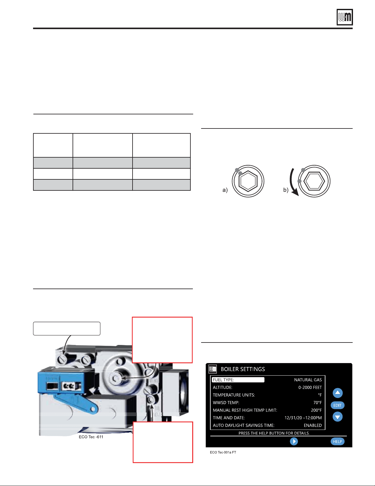
Gas Valve Course Adjustments
1. Prior to the boiler’s fi rst ignition, adjust the throttle adjustment
screw (2.5mm Allen Head) by fi rst turning the screw clockwise
(3) until it bottoms out – do not apply any additional or excess
torque. Adjust the throttle screw in a counterclockwise (4)
direction with precisely the number of turns listed in Table 2,
according to the boiler model/size.
2. After the throttle has been adjusted coarsely, the offset regulating
screw must be adjusted for the 80 and 110 models. Remove the
sealed, Allen (4mm)head cap protecting the offset regulating
screw before making adjustments. It is critical to be precise for
the adjustment of the offset regulating screw. DO NOT attempt
to bottom out the offset regulating screw as was done for the
throttle adjustment. Adjustments to the offset regulating screw
should be made from the factory-provided natural gas position.
3. Reconnect wire harness to gas valve.
4. Restore electrical power, turn on gas by opening manual gas
valve and check for leaks and ensure all calls for heat & DHW
have been shut off.
Boiler
Model
Throttle Turns
(Counterclockwise 4 from
Bottom-out Position)
(Counterclockwise 4
Factory NG Position )
80/110 LP
6-3/4 1/8
150 LP
10-3/4 0
199 LP
13 0
Gas valve adjustment locations—ONLY for use
by a qualifi ed technician, using properly working,
calibrated combustion test instruments.
Offset regulating screw adjustment—(a)
Marking factory-provided NG position. (b)
View after turn CCW adjustment.
Gas conversions (continued)
Adjust the offset regulating screw using the
following steps, referencing Figure 19 :
1. After removing cap, insert Allen wrench into offset hex
feature (4mm Allen Head) and mark position of wrench
on offset housing.
2. Turn the offset regulating screw counterclockwise (4),
according to ensuring that the Allen wrench is
moved accordingly, as shown in Figure 19 b.
Final Conversion Steps
1. When boiler has not been fi red, follow instructions on the
initial screens to select propane as the gas type and ensure all
calls for heat & DHW have been shut off. If natural gas was
already selected in the boiler control, the gas type parameter
will need to be adjusted. In the contractor menu, under
the Boiler Settings menu, adjust the “Fuel Type” setting to
“ Propane”, see Figure 81, page 88 .
2. Before fi ring, verify that the Boiler Settings are for LP gas,
“Max Rate” for the input (priority) used to fi re the boiler is
set between 96% and 100%. Also verify that the ‘Min Rate”
is set to 10%. Adjust control settings if not at proper rate.
Verify that boiler is operating at the expected fi ring rate at
both high- and low-fi re during combustion analysis. Refer
to Figure 99, page 111 for proper low-fi re rate based on
altitude settings.
Course adjustment settings — Throttle and offset
adjustments to be made prior to fi rst ignition, by size.
ECO
Tec fuel type setting screen
Turn clockwise
to increase CO
2
. 3
Turn counter-clockwise to
decrease CO
2
. 4
Note: Must remove cover.
Throttle adjustment screw
Turn counter-clockwise
to increase CO
2
. 4
Turn clockwise to
decrease CO
2
. 3
Part number 550-100-260/0520
18
ECO
®
Tec
GAS-FIRED WATER BOILER – 80/110/150/199 BOILER MANUAL
Gas conversions (continued)
LP to Natural gas conversion
1. Follow the same instructions as LP conversion, except using
the correct Natural gas conversion kit, See page 15 .
2. If LP gas was already selected in the boiler control, the gas
type parameter will need to be adjusted. In the contractor
menu, under the Boiler Settings menu, adjust the “Fuel Type”
setting to “Natural Gas”.
3. Turn throttle screw clockwise until it stops, and then turn
counter-clockwise number of turns per Figure 22. Figure 22
is intended to make rough adjustment to gas valve to allow
the boiler to fire. They are NOT intended to replace proper
adjustment of combustion valves per instructions on
pages 102 and 103 of this manual.
4. Natural gas boilers do not require an orifice between the
gas pipe and the venturi.
DO NOT operate the boiler with
the jacket door removed except for inspection
and testing as directed in this manual.
Boiler Model Number of Turns
80/110 NG
150 NG 12
199 NG 14-½
Installer conversion label
Throttle screw adjustment
3. Prior to turning on the boiler, review the procedure and
control sequence for the operation of the Manual Test Mode
in the section of the Boiler Manual titled “Manual Test Mode”
starting on page 112.
The use of a flue gas analyzer is required to convert
this unit and determine proper gas valve settings.
Do not perform this conversion without a flue gas
analyzer. Improper gas valve settings can cause
severe personal injury, death, or property damage.
4. Do NOT allow the boiler to modulate freely until the
combustion analysis and adjustment is complete. Turn on and
connect properly working, calibrated combustion analyzer to
the boiler flue pipe. Fire the boiler and force it to High Fire
in Manual Test Mode. Adjust the high fire combustion first,
using the throttle adjustment screw, to the CO
2
and CO ranges
specified in Figure 94, page 103, by model size. Then, force
the boiler to Low Fire and adjust the offset regulating screw
to the CO
2
and CO ranges specified in Figure 94, page 103,
by model size. Reinstall the cap over the offset adjustment
screw. Follow the full startup instructions found in this Boiler
Manual including the section titled “Re-check the Maximum
and Minimum CO
2
and CO rate” on page 103.
5. The coarse adjustment prescribed by this manual should
result in combustion settings that allow for ignition and
are a starting point for further adjustment. If, after making
the coarse adjustments prescribed above, the boiler will not
light, turn the throttle screw only counterclockwise (4) an
additional 1/4 turn and attempt to light again. Repeat for a
total of up to one full turn. If, after following the procedure
above, the boiler still will not ignite or, during combustion
analysis, the analyzer reads less than 1.0% O
2
, contact Weil-
McLain Technical Services for assistance.
6. Check for gas leaks and confirming proper performance.
Perform Boiler Manual start-up
Perform complete start-up sequence (beginning on page 97),
including check for gas leaks and checking for proper operation.
After placing the boiler in operation, the ignition system safety
shutoff device must be tested, page 103.
Install front door
Install front door after servicing. The front door
must be securely fastened to the boiler frame to
prevent boiler from drawing air from inside the
boiler room. This is particularly important if
the boiler is located in the same room as other
appliances. Failure to keep the door securely fastened
could result in severe personal injury or death.
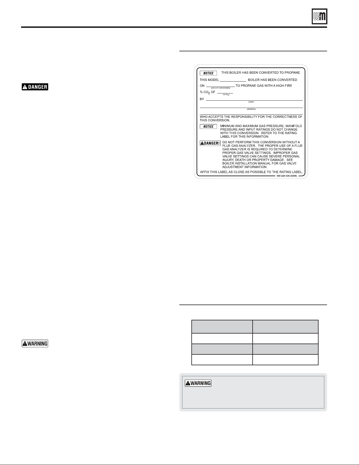
Apply installer conversion label
1. After installation is complete and boiler is set up for propane
gas, fill out and attach the propane conversion label next to
the boiler rating label (right side of cabinet).
2. Contractor/installer is responsible for completing the
information required on label (provided in kit) and attaching
installer conversion label next to the boiler rating label.
Part number 550-100-260/0520
19
ECO
®
Tec
GAS-FIRED WATER BOILER – 80/110/150/199 BOILER MANUAL
Gas piping — sizing gas lines
Boiler gas connection is ½" NPT. Size gas lines large
enough to provide gas to all connected appliances.
Natural Gas:
1. Size gas piping from meter outlet to entrance of boiler in
accordance with Figure 23 and Figure 24.
2. Use total input of all connected appliances. Divide total input
in Btuh by 1,000 to obtain cubic feet per hour of natural gas.
a. Pipe lengths in Figure 23 are equivalent length of straight
pipe. Convert pipe fittings to equivalent lengths using data
from Figure 24.
b. Figure 23 is only for natural gas with specific gravity 0.60,
with a pressure drop through the gas piping as listed in
the table.
c. For additional gas pipe sizing information, refer to ANSI
Z223.1 NFPA 54 – latest edition (or Natural Gas and
Propane Installation CAN/CSA B149.1 or B149.2 for
Canadian installations).
1. Pressure required at gas valve inlet pressure port, see
Figure 93, page 102:
a. Maximum: 14" (355 mm) w.c. with no flow (lockup).
b. Minimum gas pressure, with gas flowing (verify during
boiler startup, while boiler is at high fire):
ECO
Tec
80: 3½" (89 mm) w.c.
ECO
Tec
110: 3½" (89 mm) w.c.
ECO
Tec
150/199: 3½" (89 mm) w.c.
c. Nominal gas pressure: 7.0" (178 mm) w.c.
2. Install 100% lockup gas pressure regulator in supply line if
inlet pressure can exceed 14" w.c. at any time. Adjust lockup
regulator for 14" w.c. maximum.
Propane Gas:
You must follow the instructions, beginning on
page 14, to operate the boiler on propane. Failure to
comply could result in severe personal injury, death
or substantial property damage.
1. Contact gas supplier to size pipes, tanks and 100% lockup gas
pressure regulator.
inches
½
3.6 2.2 1.7 4.2
¾
4.4 2.3 2.4 5.3
1
5.2 2.7 3.2 6.6
1¼
6.6 3.2 4.6 8.7
1½
7.4 3.4 5.6 9.9
2
8.5 3.6 7.7 12.0
2½
9.3 4.0 9.3 13.0
Cubic feet per hour, natural gas, 0.60 specific gravity
Gas pressure 13" (330 mm) w.c. or less
Pressure drop 0.3 inches (7.6 mm) w.c
.
10 132 278 520 1050 1600 3050 4800
20 92 190 350 730 1100 2100 3300
30 73 152 285 590 890 1650 2700
40 N/A 130 245 500 760 1450 2300
50 N/A 115 215 440 670 1270 2000
75 N/A 105 175 360 545 1020 1650
100 N/A 96 150 305 460 870 1400
150 N/A 90 120 250 380 710 1130
1. Adjust propane supply regulator provided by gas supplier for
14" (355 mm) w.c. maximum pressure.
2. Pressure required at gas valve inlet pressure port, see
Figure 93, page 102:
a. Maximum: 14" (355 mm) w.c. with no flow (lockup).
b. Minimum gas pressure, with gas flowing (verify during
boiler startup, while boiler is at high fire):
ECO
Tec
80: 3½" (89 mm) w.c.
ECO
Tec 110: 3½" (89 mm) w.c.
ECO
Tec 150/199: 3½" (89 mm) w.c.
c. Nominal gas pressure: 11.0" (279 mm) w.c.
Pipe capacity for 0.60 specific gravity
natural gas; pipe length is in equivalent
feet.
Equivalent lengths of straight pipe for
typical gas line fittings.
Part number 550-100-260/0520
20
ECO
®
Tec
GAS-FIRED WATER BOILER – 80/110/150/199 BOILER MANUAL
When removing a boiler from an
existing common vent system
ECO
Tec
. When an existing boiler is replaced with an ECO
Tec
boiler, the ECO
Tec
boiler CANNOT use the existing common
vent. The boiler requires its own vent and air piping, as specified
in this manual. This may cause a problem for the appliances that
remain on the old common vent, because the vent may be too large.
The following test is intended to check for proper operation of the
appliances remaining on the old common vent system.
Perform the test sequence below for appliance remaining on the
original common vent system. Operate each appliance individually,
with other appliances turned off. This procedure will test whether
the common vent system can properly vent each appliance.
Existing vent test procedure
(The following is intended to test whether the appliances
remaining on an existing vent system will operate satisfactorily.)
1. Seal any unused openings in the common venting system.
2. Visually inspect the venting system for proper size and
horizontal pitch and determine there is no blockage or
restriction, leakage, corrosion or other deficiencies which could
cause an unsafe condition.
3. Test vent system — Insofar as is practical, close all building
doors and windows and all doors between the space in which
the appliances remaining connected to the common venting
system are located and other spaces of the building. Turn on
clothes dryers and any appliance not connected to the common
venting system. Turn on any exhaust fans, such as range hoods
and bathroom exhausts, so they will operate at maximum speed.
Do not operate a summer exhaust fan. Close fireplace dampers.
Any improper operation of a common venting system should be
corrected so the installation conforms with the National Fuel Gas
Code, ANSI Z223.1/NFPA 54 – latest edition, and/or the Natural
Gas and Propane Installation Code, CAN/CSA B149.1. When
resizing any portion of a common venting system, the common
venting system should be resized to approach the minimum size
as determined using the appropriate tables in Chapter 13 of the
National Fuel Gas Code, ANSI Z223.1/NFPA 54 – latest edition,
and/or the Natural Gas and Propane Installation Code, CAN/
CSA B149.1.
Do not install the ECO
Tec boiler into a common
vent with any other appliance. This will cause flue
gas spillage or appliance malfunction, resulting in
possible severe personal injury, death or substantial
property damage.
Existing common vent systems may be too large
for the appliances remaining connected after the
existing boiler is removed.
Failure to follow all instructions can result in
flue gas spillage and carbon monoxide emissions,
causing severe personal injury or death.
Products to avoid
Permanent wave solutions
Chlorinated waxes/cleaners
Chlorine-based swimming pool chemicals
Calcium chloride used for thawing
Sodium chloride used for water softening
Refrigerant leaks
Paint or varnish removers
Hydrochloric acid/muriatic acid
Cements and glues
Antistatic fabric softeners used in clothes dryers
Chlorine-type bleaches, detergents, and cleaning solvents
found in household laundry rooms
Adhesives used to fasten building products and other similar
products
Excessive dust and dirt
Areas likely to have contaminants
Dry cleaning/laundry areas and establishments
Swimming pools
Metal fabrication plants
Beauty shops
Refrigeration repair shops
Photo processing plants
Auto body shops
Plastic manufacturing plants
New building construction
Remodeling areas
Garages with workshops
Venting/air piping — general
4. Place in operation the appliance being inspected. Follow the
lighting instructions. Adjust thermostat so appliance will
operate continuously.
5. Test for spillage at draft hood relief opening after 5 minutes of
main burner operation. Use the flame of a match or candle,
or smoke from a cigarette, cigar, or pipe.
6. After it has been determined that each appliance remaining
connected to the common venting system properly vents
when tested as outlined herein, return doors, windows,
exhaust fans, fireplace dampers, and any other gas-burning
appliance to their previous conditions of use.
Corrosive contaminants and sources

Part number 550-100-260/0520
21
ECO
®
Tec
GAS-FIRED WATER BOILER – 80/110/150/199 BOILER MANUAL
.
Install air inlet piping for the ECO
Tec boiler as
described in this manual.
The air termination fitting must be installed with
the clearances and geometry relative to the vent
outlet depicted in this manual to ensure that flue
products do not enter the air intake.
Ensure that the combustion air will not contain
any of the contaminants in Figure 25, page 20. Do
not pipe combustion air near a swimming pool, for
example. Avoid areas subject to exhaust fumes from
laundry facilities. These areas will always contain
contaminants.
Contaminated combustion air will damage
the boiler, resulting in possible severe personal
injury, death or substantial property damage.
Installing vent and air piping
For polypropylene applications, comply with
any additional requirements in the vent system
manufacturer’s instructions. 3" PP can be used for
vent and air connections. Install a locking collar at
every joint.
Provide 3" transitions at the boiler connections if
using 2" piping.
Refer to page 137 for a list of compliant adapters.
3" to 2" PP adapter must have smooth, straight
section of pipe to insert in to the boiler vent and
air connections and must fit and seal tightly. PP
adapters with their own seal which would interfere
with the internal seal of the boiler vent or air
connections must not be used.
Additional vent and air transition pieces at
termination may be required if different material
and/or size is used for termination.
For AL29-4C vent pipe applications, comply with
any additional requirements in the vent system
manufacturer’s instructions.
3" Simpson Duravent can be used at the vent
and air connections. All other stainless steel
manufacturer's venting will require a transition
piece as per manufacturer's recommendation when
transitioning from PVC to SS.
Additional vent and air transition pieces at
termination may be required if different material
and/or size is used for termination.
Provide 3" transitions at the boiler connections if
using 2" piping.
Refer to page 137 for a list of compliant adapters.
Venting/air piping — general
Venting with flexible polypropylene
Tests have determined that flex vent has a greater pressure drop
than rigid polypropylene vent which changes the maximum
allowable length of venting. Below are the equivalent lengths.
Supplier and Size of Flex Pipe Vent Length
- Equivalent
Duravent 2” diameter
1 foot equals 3.3 ft.
Duravent 3” diameter
1 foot equals 1.7 ft.
Centrotherm 2” diameter
1 foot equals 5.0 ft.
Centrotherm 3” diameter
1 foot equals 2.3 ft.
: Using 20 feet of Duravent 3”: 20’ x 1.7 = 34’ of
equivalent length of straight pipe
Knowing and identifying the correct equivalent length is
essential to ensure the proper operation of our high efficiency
boilers. The equivalent vent lengths for each specific size and
manufacturer of venting.
Calculated equivalent feet shall not exceed maximum values
listed in boiler manual.
All current boiler installations using polypropylene flex
venting with concerns/questions should contact Weil-Mclain
Technical Service for assistance, if our boiler is having
operation issues that may be related to excess vent lengths.
Code Compliance
Venting / Combustion air piping – Installations must provide
provisions for combustion and ventilation air in accordance
with the section “Venting of Equipment”, of the National
Fuel Gas Code, ANSI Z223.1 / NFPA 54 – latest edition,
or “Venting Systems and Air Supply for appliances” of the
Natural Gas and Propane Installation Code, CAN/CSA
B149.1, or applicable provisions of the local building codes.
Part number 550-100-260/0520
22
ECO
®
Tec
GAS-FIRED WATER BOILER – 80/110/150/199 BOILER MANUAL
Venting & air — general (continued)
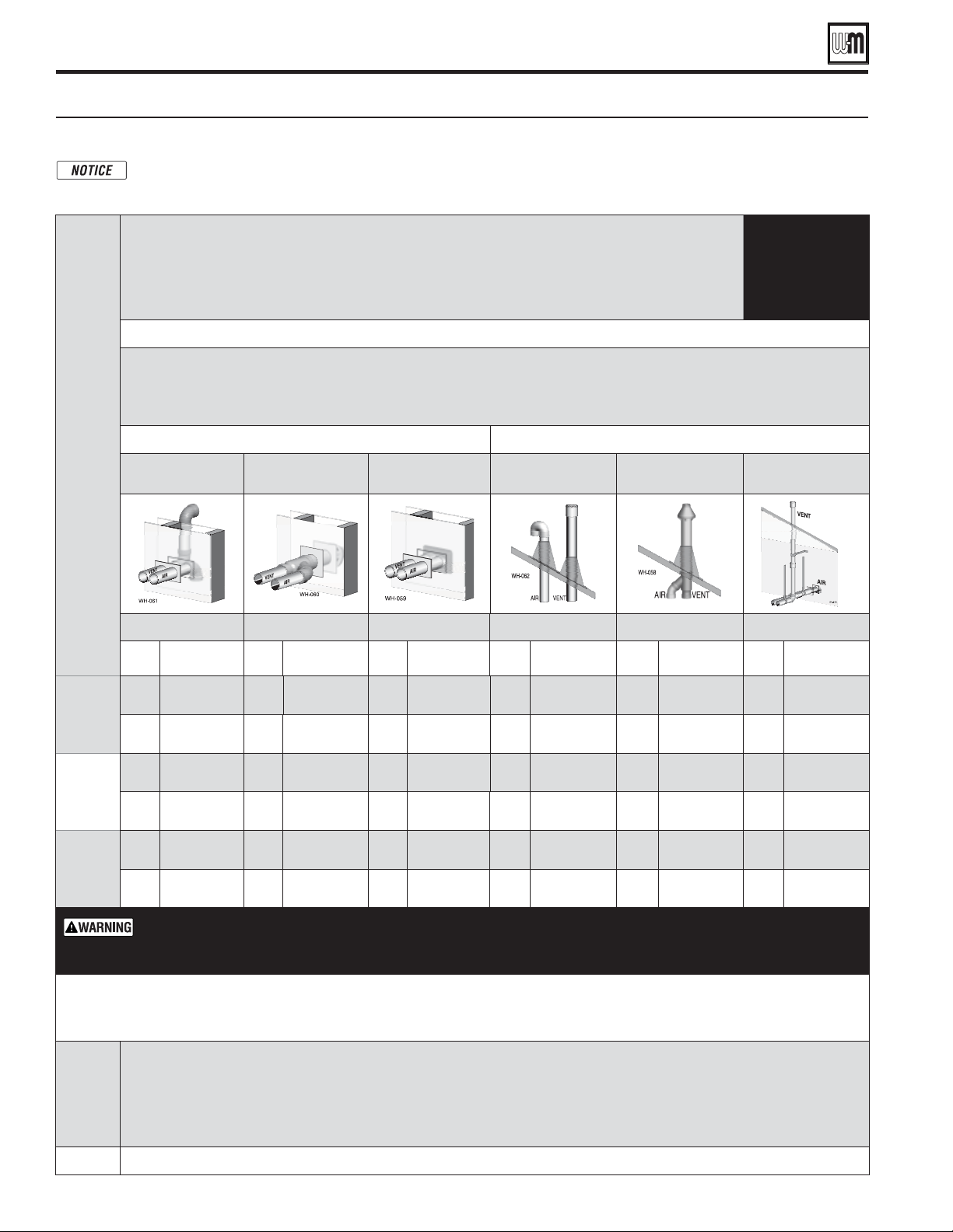
Venting and air piping — DIRECT VENT ONLY — OPTIONS and PIPING LIMITS
The table below lists the acceptable vent/air pipe terminations described in this manual. Follow all instructions provided to install the
vent/air system. below, but also approved, are the polypropylene piping and terminations listed in Figure 27, page 23.
For these applications, use ONLY the manufacturers’ parts listed and follow all instructions provided by the pipe manufacturer.
ECO
Tec
Model
Maximum vent and air pipe length (for each)
80/110/150 - 2" & 3" = 100 feet
199 - 3" = 100 feet / 199 -2" = 50 feet
(Minimum length for all applications is 2 feet)
(All applications include allowance for the termination fittings plus one elbow in air piping and one elbow in vent piping).
USE
SWEEP
ELBOWS
ONLY
See Figure27,page23 for material specications | See Figure125,page137 for part/kit numbers
Vent and air pipe sizes:
Maximum vent lengths apply for either 2" or 3" vent and air pipe.
If using 2" pipe, provide 3"x 2" tapered reducers at boiler connections and at Weil-McLain vent/air cap or at concentric terminations.
Boilers will derate as vent/air pipe length increases — see rating data on Figure138,page149 for derate amounts.
SIDEWALL termination VERTICAL termination
Separate pipes
[Note 1]
PVC or PP Concentric
[Note 1 & 2]
3” Weil-McLain PVC
vent/air cap [
Note 1 & 2]
Separate pipes
[Note 1]
PVC or PP Concentric
[Note 1 & 2]
Vertical vent,
Side Air [Note 1]
See page 28 See page 30 See page 32 See page 34 See page 36 See page 38
Size,
inches
Materials
Fig. 27, page 23
Size,
inches
Materials
Fig. 27, page 23
Size,
inches
Materials
Fig. 27, page 23
Size,
inches
Materials
Fig. 27, page 23
Size,
inches
Materials
Fig. 27, page 23
Size,
inches
Materials
Fig. 27, page 23
80/110
2
PVC/PVC-DWV
CPVC, PP, SS
2
PVC/PVC-DWV
CPVC, PP, SS
2
PVC/PVC-DWV
CPVC, PP, SS
2
PVC/PVC-DWV
CPVC, PP, SS
2
PVC/PVC-DWV
CPVC, PP, SS
2
PVC/PVC-DWV
CPVC, PP, SS
3
PVC/PVC-DWV
CPVC, PP, SS
3
PVC/PVC-DWV
CPVC, PP, SS
3
PVC/PVC-DWV
CPVC, PP, SS
3
PVC/PVC-DWV
CPVC, PP, SS
3
PVC/PVC-DWV
CPVC, PP, SS
3
PVC/PVC-DWV
CPVC, PP, SS
150
2
PVC/PVC-DWV
CPVC, PP, SS
2
PVC/PVC-DWV
CPVC, PP, SS
2
PVC/PVC-DWV
CPVC, PP, SS
2
PVC/PVC-DWV
CPVC, PP, SS
2
PVC/PVC-DWV
CPVC, PP, SS
2
PVC/PVC-DWV
CPVC, PP, SS
3
PVC/PVC-DWV
CPVC, PP, SS
3
PVC/PVC-DWV
CPVC, PP, SS
3
PVC/PVC-DWV
CPVC, PP, SS
3
PVC/PVC-DWV
CPVC, PP, SS
3
PVC/PVC-DWV
CPVC, PP, SS
3
PVC/PVC-DWV
CPVC, PP, SS
199
2
CPVC, PP, SS
2
CPVC, PP, SS
2
CPVC, PP, SS
2
CPVC, PP, SS
2
CPVC, PP, SS
2
CPVC, PP, SS
3
PVC/PVC-DWV
CPVC, PP, SS
3
PVC/PVC-DWV
CPVC, PP, SS
3
PVC/PVC-DWV
CPVC, PP, SS
3
PVC/PVC-DWV
CPVC, PP, SS
3
PVC/PVC-DWV
CPVC, PP, SS
3
PVC/PVC-DWV
CPVC, PP, SS
t
Equivalent feet for elbows (USE SWEEP ELBOWS ONLY) —
deduct from max. equivalent length of piping (does not apply to termination fittings).
PVCtGFFUQFSGPSFBDIBEEJUJPOBM¡TXFFQFMCPXPS¡FMCPX
*GQJQJOHDPOUBJOTNPSFUIBOFMCPXJOBJSPSWFOUQJQJOHPUIFSUIBOUFSNJOBUJPOmUUJOHT
PP & SS t4FFNBOVGBDUVSFSTSFDPNNFOEBUJPOTGPSFRVJWBMFOUWFOUMFOHUIQFSFMCPX
Note 1:
"#4NBZCFVTFEGPS*OUBLFBJS
.BUFSJBMBCCSFWJBUJPOT11QPMZQSPQZMFOF44"-$TUBJOMFTTTUFFM
*GVTJOHQPMZQSPQZMFOFPSTUBJOMFTTQJQFQSPWJEFBEBQUFSTUPGPSwCPJMFSDPOOFDUJPOTBOEGPSUFSNJOBUJPOTJGSFRVJSFE*1&9w17$DPODFOUSJD
WFOULJUTDBOCFVTFEXJUITUBOEBSE17$QJQFmUUJOHTBOEDFNFOU"/4*"45.%FYDFQUJG6-$4DPNQMJBODFJTSFRVJSFE'PS6-$
4DPNQMJBODFBMMQJQFmUUJOHTBOEDFNFOUNVTUCF*1&94ZTUFN*GVTJOH*1&9LJUTVTFPOMZ*1&9QSPEVDUDPEFGPSwWFOUJOH
$POUBDU8FJM.D-BJOGPSPSEFSJOHJOGPSNBUJPOBOEBWBJMBCJMJUZPG8FJM.D-BJOWFOUJOHLJUT
Note 2:
6TFPOMZ8FJM.D-BJOBQQSPWFEUFSNJOBUJPOLJUTMJTUFEJO'JHVSFQBHF
Part number 550-100-260/0520
23
ECO
®
Tec
GAS-FIRED WATER BOILER – 80/110/150/199 BOILER MANUAL
Venting & air — general (continued)
Vent and air piping materials — Use only the materials listed below, ensuring that all materials meet
local codes (see Figure 125, page 137 for part/kit numbers)
ALL vent and air pipes require a BIRD SCREEN at each termination. Most kits do not include
the bird screens. Purchase bird screens separately from Weil-McLain or vent kit supplier if
not included. [Note — bird screening is integral to the 3" PVC Weil-McLain sidewall vent
cap,
available for purchase from Weil-McLain
. No additional screening is required.]
USE SWEEP ELBOWS FOR ALL VENT AND AIR PIPING — DO NOT use short radius
elbows for vent or air piping. Boiler performance could be a ected.
(Note 2)
&
PVC schedule 40 (Note 1) ANSI/ASTM D1785 ULC S636
ABS,
PVC, PVC-DWV,
CPVC or
polypropylene
PVC-DWV schedule 40 (Note 1) ANSI/ASTM D2665 N/A
CPVC schedule 40 (Note 1) ANSI/ASTM F441 ULC S636
ABS-DWV schedule 40 (Intake Only) ANSI/ASTM D2661 ULC S636
PVC (Note 1) ANSI/ASTM D2564/F656 ULC S636
Use only cement
and primer
suitable for piping
material used
CPVC (Note 1) ANSI/ASTM F493 ULC S636
ABS schedule 40 (Note 1) ANSI/ASTM D2235 ULC S636
Obtain all materials from M&G
Simpson-Duravent
®
Obtain all materials from Centrotherm
Note: See
page 137 for correct appliance adapters to be used.
See manufacturer’s literature for
detailed information
MUST USE LOCKING
COLLAR ON EVERY JOINT
ULC S636
PVC, PVC-DWV,
CPVC or
polypropylene
Heat Fab, Inc. — Saf-T-Vent
®
Z-Flex, Inc. — Z-Vent II
Dura-Vent — FasNSeal™
Metal-Fab, Inc. — CORR/GUARD
See Figure 125, page 137 for Mfg's adapter
part numbers.
Certifi ed for Category IV and
direct vent appliance venting
Certifi ed for Category IV and direct
vent appliance venting
(purchase separately) — see Figure 125, page 137 for part numbers.
Note 1: Weil-McLain concentric vent kits are made from PVC
pipe and ttings.
Note 2: System 636 PVC concentric terminations utilize PVC
pipe/ ttings certi ed to ULC S636.
If ULC S636 compliance is required, use only System 636
pipe, ttings and cement.
DO NOT mix piping from di erent pipe manufacturers
unless using adapters speci cally designed for the purpose
by the manufacturer.
Every joint on polypropylene vent piping must include
a locking collar.
DO NOT use cellular core PVC (ASTM F891), cellular core
CPVC, or Radel
®
(polyphenolsulfone) in venting systems.
DO NOT cover non-metallic vent pipe and ttings with
thermal insulation.
ADAPTERS — The boiler comes with a 3" 3-in-
1 adapter as standard. This adapter allows the
installation of 3" PVC schedule 40, CPVC schedule
40, PVC-DWV schedule 40, AL29-4C stainless steel
(from Simpson-Duravent only) and Polypropylene
(from Simpson-Duravent & Centrotherm only)
piping without the need for extra adapters.
ADAPTERS – It may require additional adapters at the
terminations if using di erent venting materials.
(When going from PP to the Weil-McLain side wall
plate, for example).
ADAPTERS - If using 2" piping, where approved for
the application, provide adapters for a 3" pipe
material (mentioned above) connections and at
the terminations, if required.

Part number 550-100-260/0520
24
ECO
®
Tec
GAS-FIRED WATER BOILER – 80/110/150/199 BOILER MANUAL
(a) For all sidewall horizontally-vented gas-fueled equipment
installed in every dwelling, building or structure used in
whole or in part for residential purposes, including those
owned or operated by the Commonwealth and where the
side wall exhaust vent termination is less than seven (7) feet
above finished grade in the area of the venting, including but
not limited to decks and porches, the following requirements
shall be satisfied:
1.
.
At the time of installation of the side wall horizontal
vented gas fueled equipment, the installing plumber
or gas fitter shall observe that a hard wired carbon
monoxide detector with an alarm and battery back-up
is installed on the floor level where the gas equipment is
to be installed. In addition, the installing plumber or gas
fitter shall observe that a battery operated or hard wired
carbon monoxide detector with an alarm is installed
on each additional level of the dwelling, building or
structure served by the side wall horizontal vented gas
fueled equipment. It shall be the responsibility of the
property owner to secure the services of qualified licensed
professionals for the installation of hard wired carbon
monoxide detectors.
a. In the event that the side wall horizontally vented gas
fueled equipment is installed in a crawl space or an
attic, the hard wired carbon monoxide detector with
alarm and battery back-up may be installed on the
next adjacent floor level.
b. In the event that the requirements of this subdivision
can not be met at the time of completion of
installation, the owner shall have a period of thirty
(30) days to comply with the above requirements;
provided, however, that during said thirty (30) day
period, a battery operated carbon monoxide detector
with an alarm shall be installed.
2.
. Each
carbon monoxide detector as required in accordance with
the above provisions shall comply with NFPA 720 and be
ANSI/UL 2034 listed and IAS certified.
3.
. A metal or plastic identification plate shall
be permanently mounted to the exterior of the building
at a minimum height of eight (8) feet above grade
directly in line with the exhaust vent terminal for the
horizontally vented gas fueled heating appliance or
equipment. The sign shall read, in print size no less than
one-half (1/2) inch in size, “GAS VENT DIRECTLY
BELOW. KEEP CLEAR OF ALL OBSTRUCTIONS.”
4.
. The state or local gas inspector of the
side wall horizontally vented gas fueled equipment shall
not approve the installation unless, upon inspection,
the inspector observes carbon monoxide detectors and
signage installed in accordance with the provisions of
248 CMR 5.08(2)(a) 1 through 4.
(b)
: The following equipment is exempt from
248 CMR 5.08(2)(a)1 through 4:
1. The equipment listed in Chapter 10 entitled “Equipment
Not Required To Be Vented” in the most current edition
of NFPA 54 as adopted by the Board; and
2. Product Approved side wall horizontally vented gas fueled
equipment installed in a room or structure separate from
the dwelling, building or structure used in whole or in
part for residential purposes.
(c)
. When the manufacturer
of Product Approved side wall horizontally vented gas
equipment provides a venting system design or venting system
components with the equipment, the instructions provided
by the manufacturer for installation of the equipment and
the venting system shall include:
1. Detailed instructions for the installation of the venting
system design or the venting system components; and
2. A complete parts list for the venting system design or
venting system.
(d)
. When the manufacturer
of a Product Approved side wall horizontally vented gas fueled
equipment does not provide the parts for venting the flue
gases, but identifies “special venting systems”, the following
requirements shall be satisfied by the manufacturer:
1. The referenced “special venting system” instructions shall
be included with the appliance or equipment installation
instructions; and
2. The “special venting systems” shall be Product Approved
by the Board, and the instructions for that system shall
include a parts list and detailed installation instructions.
(e) A copy of all installation instructions for all Product Approved
side wall horizontally vented gas fueled equipment, all venting
instructions, all parts lists for venting instructions, and/or all
venting design instructions shall remain with the appliance
or equipment at the completion of the installation.
Commonwealth of Massachusetts installations
Commonwealth of Massachusetts — 8IFOUIFCPJMFSJTJOTUBMMFEXJUIJOUIF$PNNPOXFBMUIPG.BTTBDIVTFUUT
UIFCPJMFSNVTUCFJOTUBMMFECZBMJDFOTFEQMVNCFSPSHBTmUUFS3FBEBOEDPNQMZXJUIUIFJOTUSVDUJPOTCFMPX
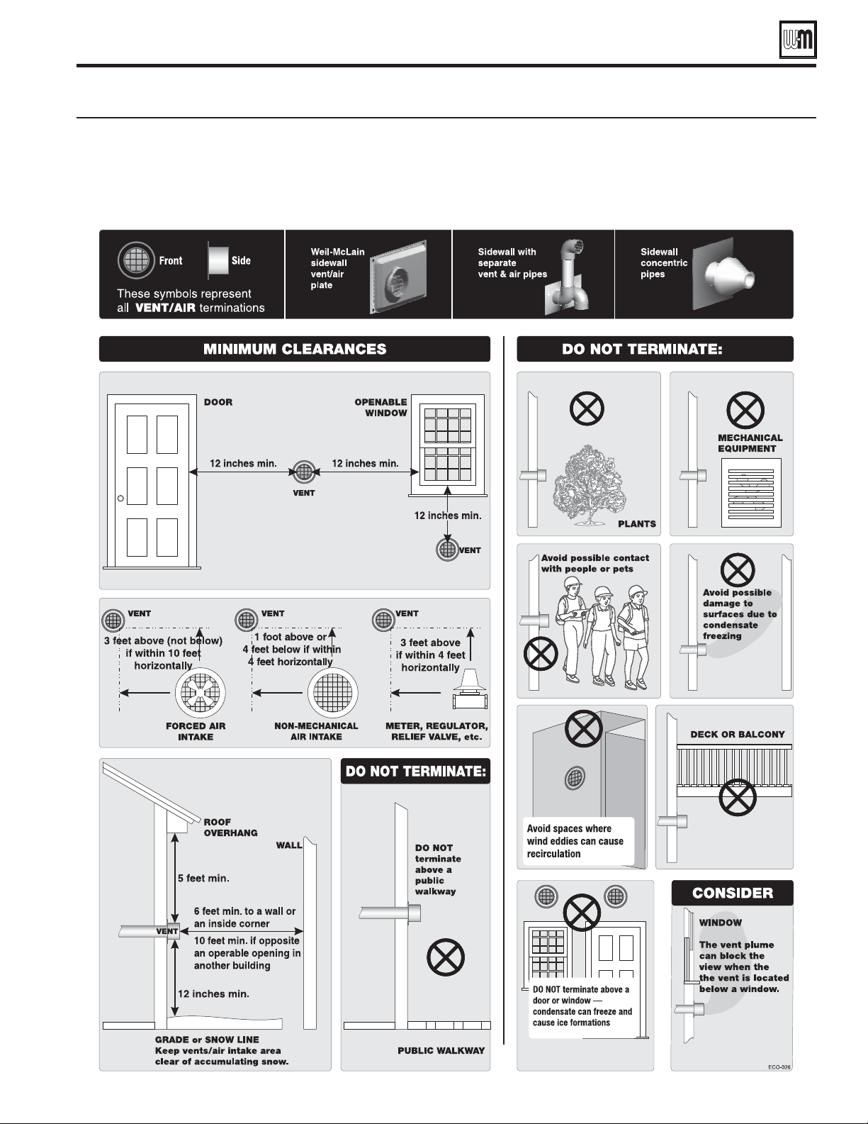
Part number 550-100-260/0520
25
ECO
®
Tec
GAS-FIRED WATER BOILER – 80/110/150/199 BOILER MANUAL
Vent termination requirements
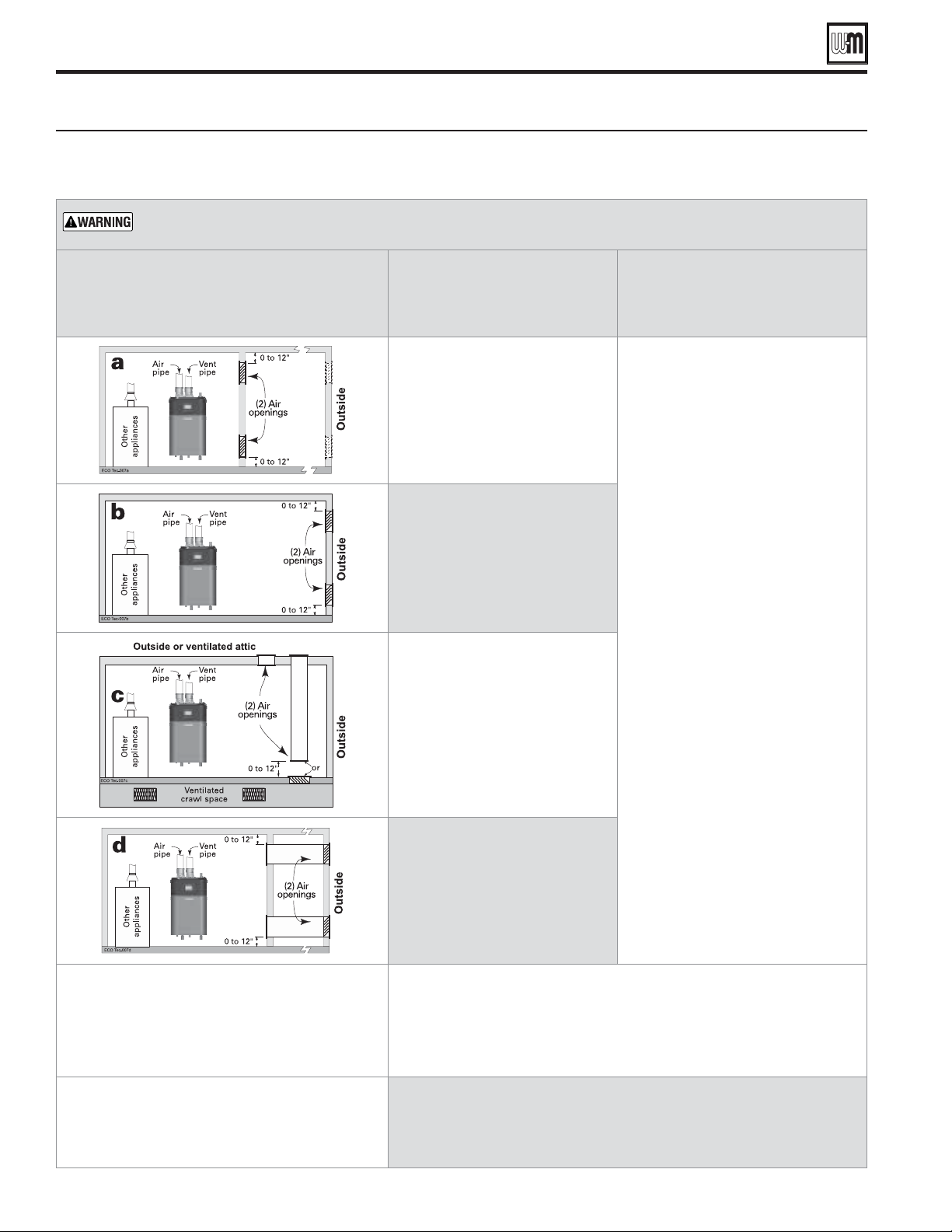
Part number 550-100-260/0520
26
ECO
®
Tec
GAS-FIRED WATER BOILER – 80/110/150/199 BOILER MANUAL
Combustion and ventilation air openings for Direct Vent installations. Also follow the National Fuel Gas
Code, ANSI Z223.1/NFPA 54 - latest edition, and/or Natural Gas and Propane Installation Code, CAN/CSA
B149.1 or applicable provisions of the local building codes.
Boiler room air openings
The ECO
Tec
boiler CANNOT be in the same space with other appliances if clearances around the boiler are less
than the recommended service clearances shown in Figure 1, page 8.
Air openings
The required air opening sizes below are FREE AREA,
after reduction for louver obstruction. Note the
exception below for large spaces.
ECO
Tec
boiler
WITH other
appliances in room
ECO
Tec boiler
WITHOUT other
appliances in room
openings, each at least:
1 square inch per Btuh
of all other appliances in the room
(Unless specified otherwise by
appliance manufacturer)
openings are required if the
boiler installation provides at least the
recommended service clearances
shown in Figure 1, page 8.
If the space is smaller than
Figure 1, page 8, provide openings
ONLY as shown in Figure 2, page 8
.
Each opening must have a free
area no less than 1 square inch per
1,000 Btuh input of the boiler.
openings, each at least:
1 square inch per Btuh
of all other appliances in the room
— OR —
opening **, each at least:
1 square inch per Btuh
of all other appliances in the room
(Unless specified otherwise by
appliance manufacturer)
openings, each at least:
1 square inch per Btuh
of all other appliances in the room
— OR —
opening **, each at least:
1 square inch per Btuh
of all other appliances in the room
(Unless specified otherwise by
appliance manufacturer)
openings, each at least:
1 square inch per Btuh
of all other appliances in the room
— OR —
opening **, each at least:
1 square inch per Btuh
of all other appliances in the room
(Unless specified otherwise by
appliance manufacturer)
A single combustion air opening can be used for cases b, c or d above ( with
other appliances in room only), sized as listed, provided that:
The single opening must communicate directly to the outdoors or to a space that
communicates directly with outdoors (NOT to an interior space).
The top of the opening must be within 12 inches of the ceiling.
The free area of the opening must be at least equal to the sum of the areas of all
equipment vent connectors in the space.
NO combustion air openings are needed if the boiler (and other appliances) are
installed in a space with a volume NO LESS than 50 cubic feet per 1,000 Btuh of all
appliances in the space. That is, total the input of all appliances in MBH (1,000’s of
Btuh), then multiply this total times 50. The building MUST NOT be of tight construction.
Example: For a total input of 500 MBH (500,000 Btuh), the minimum volume would be
50 x 500 = 25,000 cubic feet.
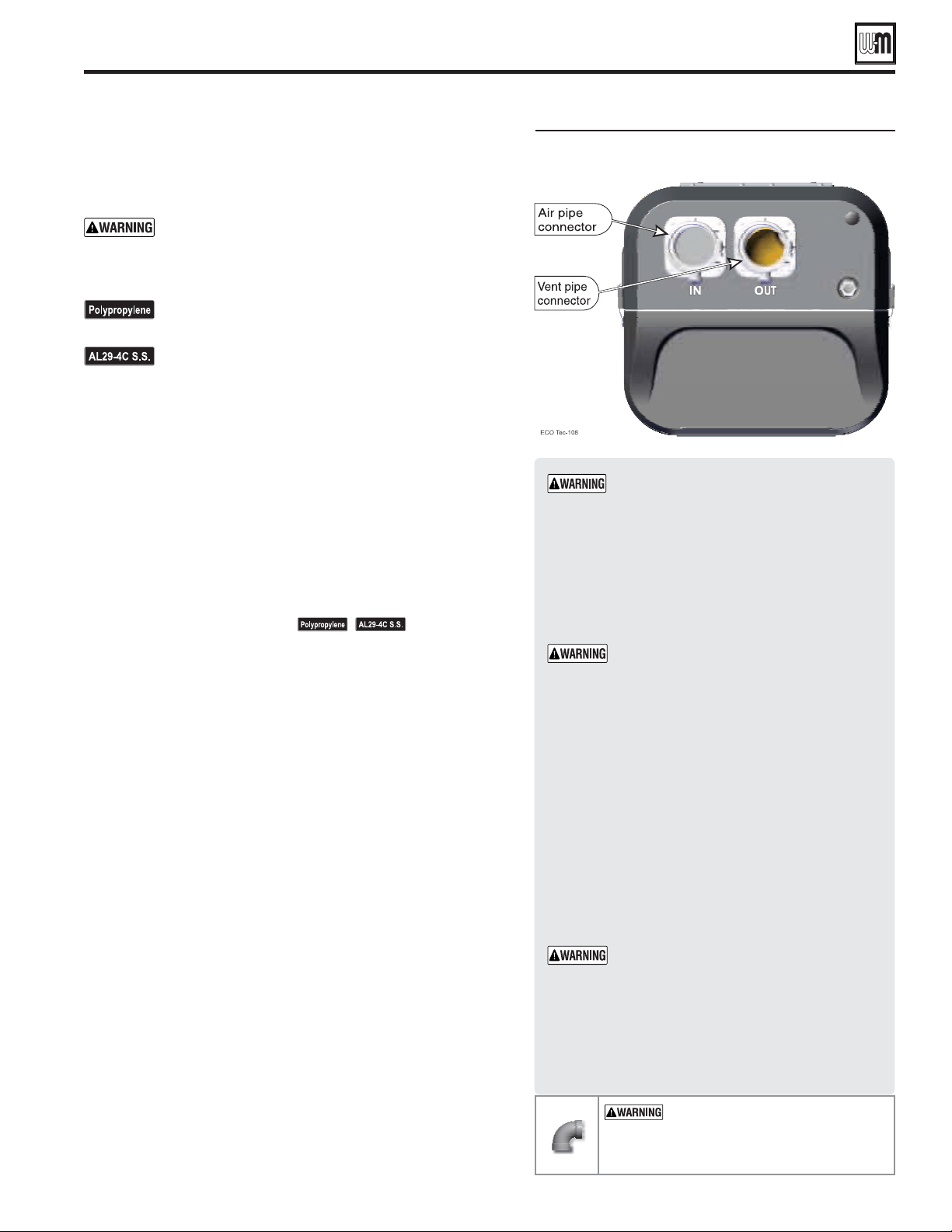
Part number 550-100-260/0520
27
ECO
®
Tec
GAS-FIRED WATER BOILER – 80/110/150/199 BOILER MANUAL
Boiler vent and air connections
Follow termination instructions
1. Read and follow all instructions for the termination type used
before proceeding with this page. Follow all instructions provided
by vent pipe manufacturer.
Use only materials from the manufacturers listed in
Figure 27, page 23 .
Installing vent and air piping
For polypropylene applications, see venting and air piping
notes on page 21 .
For AL29-4C vent pipe applications, See venting and air
piping notes on page 21 .
1. Work from the boiler to vent or air termination. Do not exceed the
lengths given in the previous pages for either the air or vent piping.
2. See Figure 30 for attaching vent (and air) pipes at the boiler.
Connections must be 3" PVC or CPVC only — use transitions if
needed to adapt to other material or size (2").
3. Cut pipe to required lengths.
4. Dry assemble entire vent or air piping to ensure proper fi t before
assembling any joint.
5. Maintain minimum clearance of
3/16 inch between vent pipe and
any combustible wall or material.
6. Seal wall or floor penetration openings following local code
requirements.
7. Assembling PVC or CPVC: (
— follow pipe
manufacturer’s instructions for preparation and assembly)
a. Deburr inside and outside of pipe ends.
b. Chamfer outside of each pipe end to ensure even cement
distribution when joining.
c. Clean all pipe ends and fi ttings. Dry thoroughly.
d. For each joint:
Handle fi ttings and pipes carefully to prevent contamination
of surfaces.
Apply primer liberally to both joint surfaces — pipe end
and fi tting socket.
While primer is still damp, lightly apply approved cement
to both surfaces in a uniform coating.
Apply a second coat to both surfaces. Avoid using too much
cement on sockets to prevent cement buildup inside.
With cement still wet, insert pipe into fi tting, twisting ¼
turn. Make sure pipe is fully inserted.
Wipe excess cement from joint. Check joint to be sure a
smooth bead of cement shows around the entire joint.
Vent and air piping and boiler connections
—
Use Adapters if using other
than 3" PVC, CPVC, SS (Simpson-Duravent
only) and PP (Simpson-Duravent &
Centrotherm).
1. Use only 3" PVC, CPVC, SS(Simpson-Duravent
only) and PP (Simpson-Duravent & Centrotherm)
pipe at boiler connection
.
2. Clean and deburr inside and outside of both ends of air
and vent pipes. Chamfer boiler end of vent pipe for ease of
insertion.
The vent pipe end must be smooth and chamfered
to prevent possible damage to sealing gasket in vent
pipe adapter.
3. Inspect vent or air adapter (above) — verify no obstructions
or foreign objects inside.
4. Loosen clamp screw.
5. Measure: PVC or CPVC = 2-
1/4
" or
PP = 3-½" or
Duravent SS = 4-
3/4
"
from end of pipe and make a mark with felt-tip pen.
6. Loosen adapter clamp screw.
7. Apply small amount of silicon grease to end of pipe to ease
insertion.
8. Insert pipe into adapter.
9. Slide pipe down until the mark is reached.
Do not apply excessive force or bend the adapter
or fl ue/air pipe when inserting. The adapter or seal
could be damaged. If any portion of the vent or air
system is damaged, it must be replaced.
10. Secure vent or air pipe by tightening the adapter clamp
securely. Do not overtighten.
11. The seal is accomplished with the internal gasket. The clamp
is only to hold the pipe in place.
— DO NOT
use short radius elbows for vent or air
piping. Boiler performance could be
affected.

— Separate pipes sidewall
Read and follow all instructions in this manual.
See notices at left and page 21 .
Install the boiler in a location that allows proper routing of all vent and air
piping to the selected sidewall location.
Make sure the selected sidewall termination location complies with
Figure 28, page 25 . (Multiple boiler sidewall plates must also comply with
Figure 32, page 29 .)
Use only the vent materials listed in Figure 27, page 23 . Provide pipe adapters
where required. Vent piping and air piping lengths must not exceed the
values shown in
Figure 26, page 22 .
Prepare the sidewall penetrations and secure the sidewall plates as instructed
in this section. See “Prepare wall penetrations” on page 29 .
See notices at left and page 21 .
The air piping must terminate in a as shown above.
The vent piping must terminate in an
as shown above. See illustration above.
Install vent and air piping between the boiler and the sidewall openings.
Slope horizontal piping downward toward the boiler at least 1/4 inch per
foot. See
page 27 for general guidelines.
See notices at
left and page 21 .
Install pipe supports every 5 feet on both the horizontal and vertical runs.
Install a hanger support within 6 inches of any upturn in the piping, or
per vent pipe manufacturer’s instructions.
See notices
at left and page 21 .
Attach the vent termination exterior piping: Use either of the confi gurations
shown above, as needed to ensure clearance above grade or snow line.
The vent and air pipes may run up as high as 4 feet with no enclosure.
The vent and air pipes must be secured with braces, and all clearances and
lengths must be maintained. Space braces no further than 24 inches apart.
External venting greater than 4 feet requires an insulated enclosure around
the vent and air pipes. The vent and air terminations must exit through
the enclosure as shown in the illustration above, maintaining all required
clearances.
— DO NOT use short radius elbows for vent or air piping. Boiler
performance could be affected.
Part number 550-100-260/0520
28
ECO
®
Tec
GAS-FIRED WATER BOILER – 80/110/150/199 BOILER MANUAL
Use only the vent materials and kits
listed in Figure 27, page 23 . Provide
pipe adapters if specifi ed.
Locate the termination such that the total air piping
and vent piping from the boiler to the termination
will not exceed the maximum length given in
Figure 26, page 22 .
For polypropylene applications,
See venting and air piping notes on
page 21 .
For AL29-4C vent pipe applications,
See venting and air piping notes on
page 21 .
1. The air and vent terminations must be installed
as shown in Figure 31 and Figure 34, page 29 .
2. The terminations must comply with clearances
and limitations shown in Figure 28, page 25 .
3. Locate the terminations so they are not likely to
be damaged by foreign objects, such as stones or
balls, or subject to buildup of leaves or sediment.
Do not exceed the maximum lengths
of the outdoor vent piping shown in
Figure 31 . Excessive length exposed to
the outdoor could cause freezing of
condensate in the vent pipe, resulting
in potential boiler shutdown. In
extremely cold climates, install an
insulated chase around the vent
piping, particularly if using longer
lengths. The chase must allow for
inspection of the vent pipe, and
insulation must be protected from
water.
1. When terminating multiple boilers, terminate
each vent/air connection as described in this
manual.
All vent pipes and air inlets must
terminate at the same height to avoid
possibility of severe personal injury,
death or substantial property damage.
2. Place wall penetrations to obtain minimum
clearances shown in Figure 32, page 29 for U. S.
installations. For Canadian installations, provide
clearances required by CSA B149.1 or B149.2
Installation Code and a ULC S636 compliant
vent kit.
3. The air inlet of a boiler is part of a direct vent
connection. It is not classifi ed as a forced air
intake with regard to spacing from adjacent
boiler vents.
DIRECT VENT — Sidewall with separate pipes
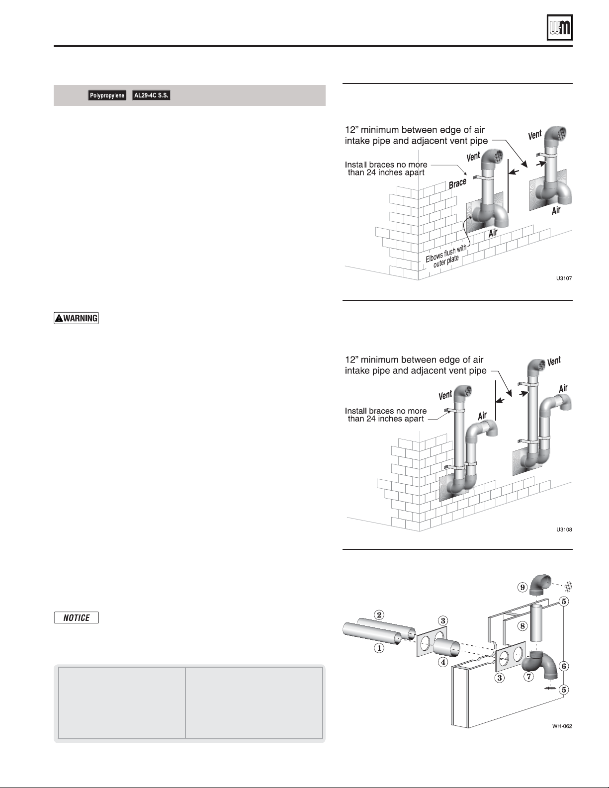
See notices on previous page.
Part number 550-100-260/0520
29
ECO
®
Tec
GAS-FIRED WATER BOILER – 80/110/150/199 BOILER MANUAL
1. Air pipe penetration:
a. Cut a hole for the air pipe. Size the air pipe hole as close as
desired to the air pipe outside diameter.
2. Vent pipe penetration:
a. Cut a hole for the vent pipe. For either combustible or
noncombustible construction, size the vent pipe hole at least
0.4" larger than the vent pipe diameter.
b. Insert a corrosion resistant metal thimble in the vent pipe hole
as shown in Figure 34.
3. Use the provided paper template for correct location of hole centers.
4. Use of a sidewall termination plate is REQUIRED.
a. Kits for several vent sizes are available from Weil-McLain.
See “VENT/AIR PARTS AND KITS” on page 137.
b. Plate may be field fabricated from corrosion resistant material
of sufficient strength. Plate must allow venting to maintain
minimum clearance to combustibles.
Ensure that the plate material is strong enough to prevent
the termination from being pushed inward if struck or
pushed from the outside.
5. Follow all local codes for isolation of vent pipe when passing
through floors or walls.
6. Seal exterior openings thoroughly with exterior caulk.
1. Prepare the vent termination elbow and the air termination elbow
by inserting bird screens. (See Figure 31, page 28.) Bird screens
must be purchased separately. See the parts list at the end of this
manual for part numbers.
2. Secure the elbows so they will butt against the sidewall termination
plate.
3. When completed, the air termination coupling must be oriented
at least 12 inches below the vent termination and at least 12 inches
above grade or snow line as shown in Figure 31, page 28.
4. You can orient the vent termination elbow either directly
outward or 90 degrees away from the air inlet elbow as shown in
Figure 31, page 28.
5. Maintain the required dimensions of the finished termination
piping as shown in Figure 31, page 28.
6. For multiple boiler terminations, see Figure 32.
7. Do not extend exposed vent pipe outside of building more than
shown in this document. Condensate could freeze and block vent
pipe.
If extending the vent and air pipes out from the wall,
install a coupling on each pipe. Mount the piping with
the coupling flush with the outer plate.
DIRECT VENT — Sidewall with separate pipes (continued)
1 Vent piping
2 Air piping
3 Sidewall termination plates: for 3" PVC,
use plates supplied with boiler in W-M
vent/air plate kit; for 3" AL29-4C or 2" PVC,
purchase optional sidewall separate pipes
plate kit
4 Corrosion resistant thimbles, by installer
5 Bird screen, by installer
6 Air inlet elbow
7 Elbow
8 Nipple
9 Elbow (vent termination)
Multiple terminations –– separate pipes ––
clearance from vent of one air intake of
the next
Multiple terminations –– separate pipes ––
clearance from vent of one air intake of
the next – alternate configuration of air
and vent terminations.
Sidewall termination assembly —
using separate pipes
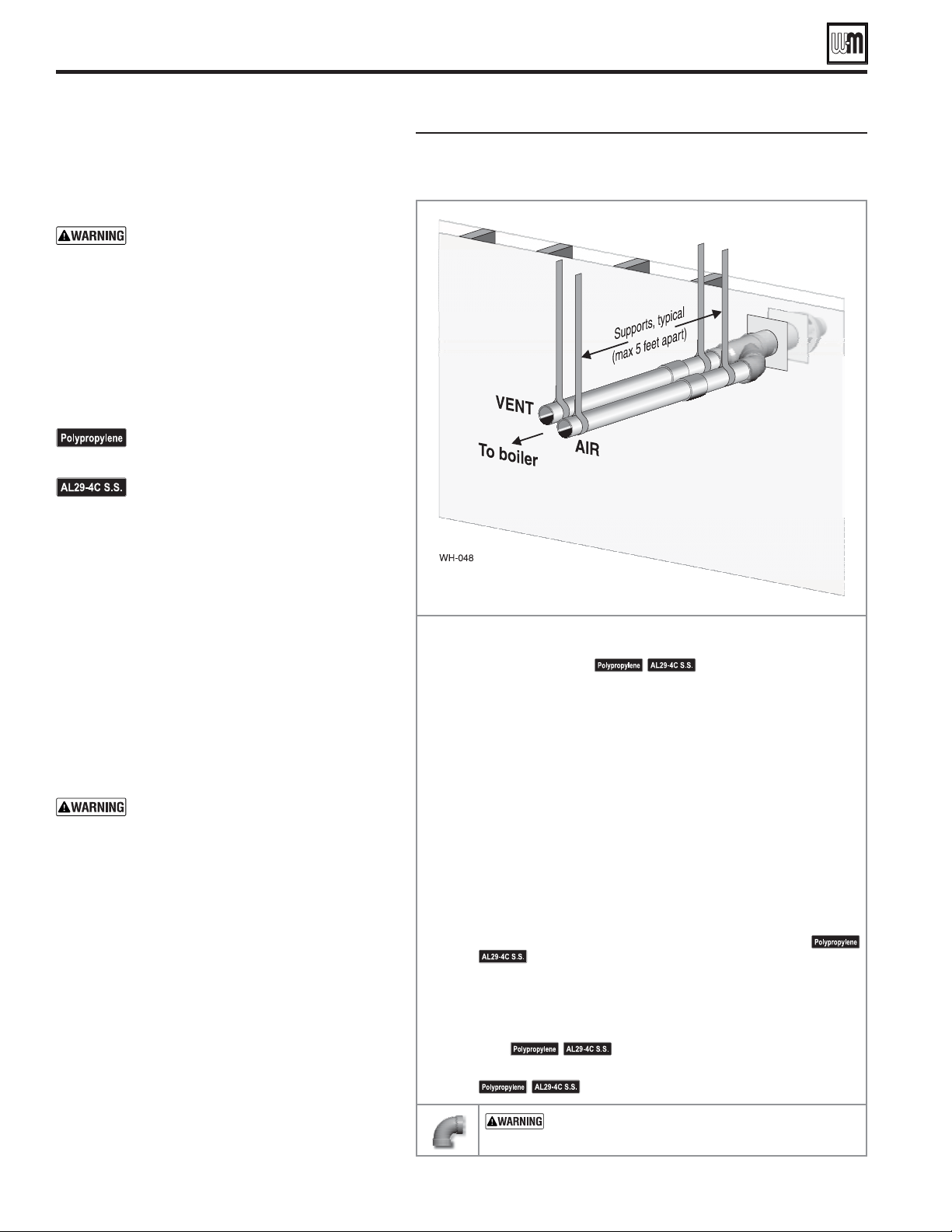
— Concentric horizontal
Read and follow all instructions in this manual.
See notices at left.
Install the boiler in a location that allows proper routing of all vent
and air piping to the selected sidewall location.
Make sure the selected sidewall termination location complies with
Figure 28, page 25 . (Multiple boiler concentric terminations must also
comply with Figure 36, page 31 .)
Use only the vent materials listed in Figure 27, page 23 . Provide pipe
adapters where required.
Vent piping and air piping lengths must not exceed the values shown
in
Figure 26, page 22 .
The concentric termination must be assembled and installed before
piping from the boiler to the termination.
Prepare the sidewall penetration — assemble the concentric
termination kit and secure the cover plates as instructed in this section.
Provide the supports indicated and mount the termination assembly.
See “Install termination — concentric pipes” on page 31 .
See notices at left.
Install vent and air piping between the boiler and the concentric vent/
air termination. Slope horizontal piping downward toward the boiler
at least 1/4 inch per foot. See page 27 for general guidelines.
Install pipe supports every 5 feet on both the horizontal and vertical
runs.
See notices at left and page 21 .
Install a hanger support within 6 inches of any upturn in the piping.
See notices at left.
— DO NOT use short radius elbows for vent or
air piping. Boiler performance could be affected.
Part number 550-100-260/0520
30
ECO
®
Tec
GAS-FIRED WATER BOILER – 80/110/150/199 BOILER MANUAL
1. The concentric termination kit must be purchased
separately.
Use only the vent materials and kits
listed in Figure 27, page 23 . Provide pipe
adapters if specifi ed.
2. Locate the termination such that the total air piping
and vent piping from the boiler to the termination
will not exceed the maximum length given in
Figure 26, page 22
.
3. This termination requires a 45-degree elbow that
is not supplied with the termination kit. The
maximum vent/air pipe lengths include allowance
for this elbow.
For polypropylene applications, See
venting and air piping notes on page 21 .
For AL29-4C vent pipe applications,
See venting and air piping notes on
page 21 .
1. The concentric termination kit must be installed
as shown in Figure 37, page 31 .
2. The termination must comply with clearances and
limitations shown in
Figure 28, page 25
.
3. Locate the termination so it is not likely to be
damaged by foreign objects, such as stones or balls,
or subject to buildup of leaves or sediment.
1. When terminating multiple boilers, install each
concentric termination as described in this manual.
All vent pipes and air inlets must
terminate at the same height to avoid
possibility of severe personal injury,
death or substantial property damage.
2. Place wall penetrations to obtain minimum
clearance as shown in Figure 36, page 31 for U. S.
installations. For Canadian installations, provide
clearances required by CSA B149.1 or B149.2
Installation Code and a ULC S636 compliant vent
kit.
3. The air inlet of a boiler is part of a direct vent
connection. It is not classifi ed as a forced air intake
with regard to spacing from adjacent boiler vents.
DIRECT VENT — Sidewall concentric
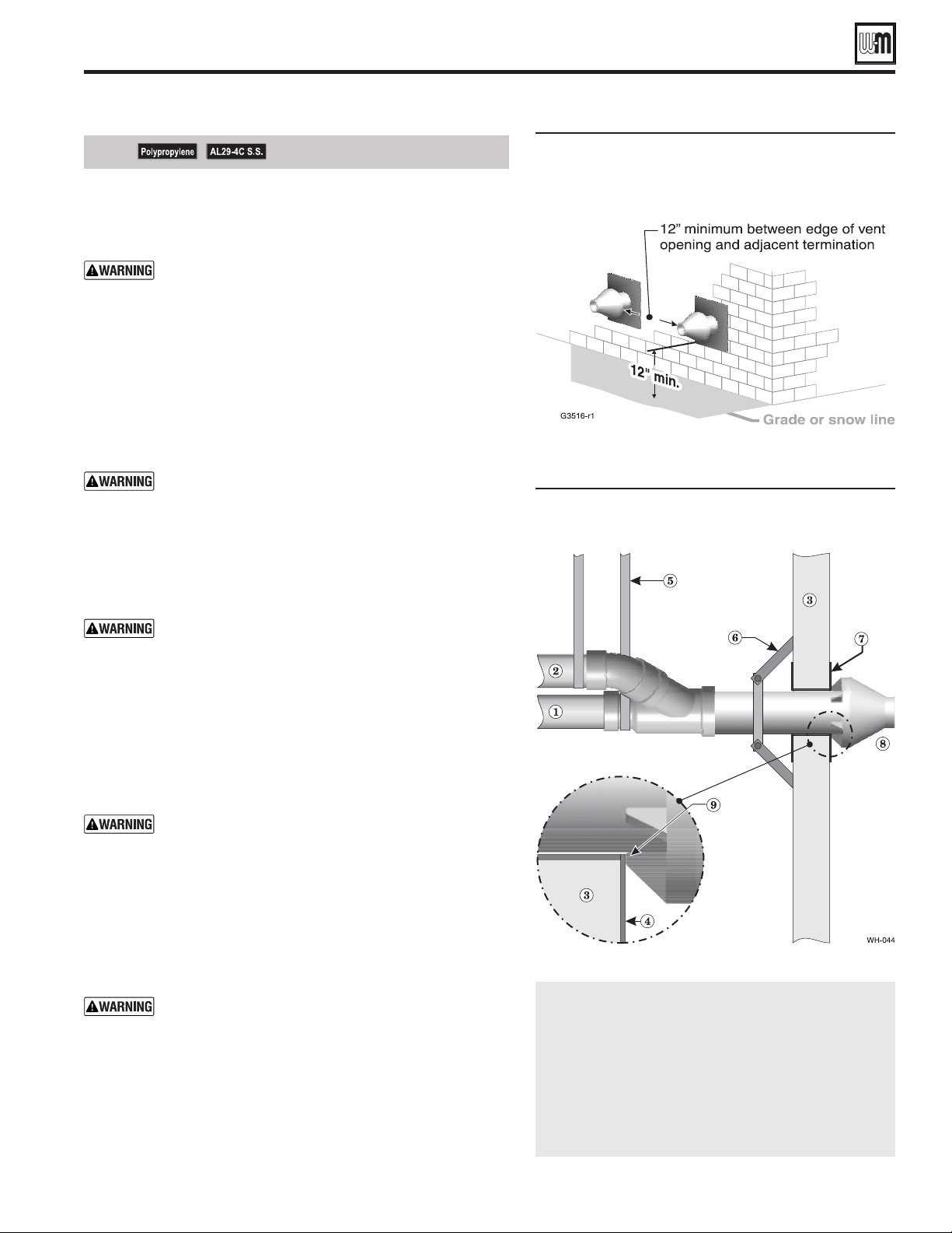
Termination location — concentric
termination — multiple boilers —
clearance from vent of one to air
intake of the next
Installing and supporting the
concentric sidewall vent assembly
Vent pipe
Air pipe
Wall
Outer thimble plate
Supports every 5 feet
or per vent pipe mfg’s
instructions
Wall brace, by installer,
(or see vent pipe mfg’s
instructions)
Thimble, by installer
Rain cap
Rain cap ribs must butt
against outer thimble
plate or wall opening
See notices on previous page.
Part number 550-100-260/0520
31
ECO
®
Tec
GAS-FIRED WATER BOILER – 80/110/150/199 BOILER MANUAL
1. Assemble the vent termination as described for concentric
terminations, on page 40.
If necessary, you can shorten the lengths of the inner and
outer pipes for a shorter finished assembly. But you must
ensure the pipes butt correctly at both ends. Failure to
properly assemble the concentric termination can result
in flue gas recirculation, causing possible severe personal
injury or death.
2. Wall penetration:
a. Preferably, use a thimble with a 4½-inch hole. If not using a
thimble, carefully use a hole saw to cut a hole not larger than
4¾ inches in diameter through the wall. The finished hole
must provide a solid stop for the rain cap ribs, as shown in the
inset to Figure 37.
Ensure that the wall material is strong enough to prevent
the rain cap from being pushed inward if struck or
pushed from the outside.
3. Secure the termination in place so the rain cap will butt against the
outside wall or outer thimble plate as shown in Figure 37.
4. Before beginning vent and air piping from the boiler to the
concentric termination, mount and secure the concentric
termination as shown in Figure 37.
The vent and air piping must be securely supported, and
must not rest its weight on the boiler fittings. Failure to
properly support the vent and air piping could result in
vent piping damage, resulting in possible severe personal
injury, death or substantial property damage.
The supports/bracing used must support the termination
assembly to prevent slippage or movement. See
instructions provided with concentric kit for details.
The clamps used on the outside of the termination pipe
must not cut into the pipe or contain sharp edges that
could cause a crack to form.
When inserting the partially-assembled termination
kit through the wall penetration, wrap plastic or other
protection over the end of the exposed assembly to
prevent debris from entering the pipes. If the air passages
become blocked, the boiler will not operate. Once the
rain cap has been cemented to the assembly, there is no
way to correct the problem. The assembly would have
to be replaced if it were cut to be removed and cleaned.
Altering the assembly in any way could result in severe
personal injury or death due to toxic flue product
emissions.
If using AL29-4C stainless vent pipe, use the vent pipe
manufacturer’s PVC adapter if connecting to a PVC
concentric vent attachment.
5. After the assembly has been positioned in the opening and all
supports have been attached, install a bird screen (purchased
separately if not included with the kit) and rain cap as follows:
a. Place the bird screen on the end of the inner pipe as in
Figure 50, page 40, or per concentric kit instructions for
polypropylene kits.
b. Cement the rain cap in place as shown.
DIRECT VENT — Sidewall concentric (continued)
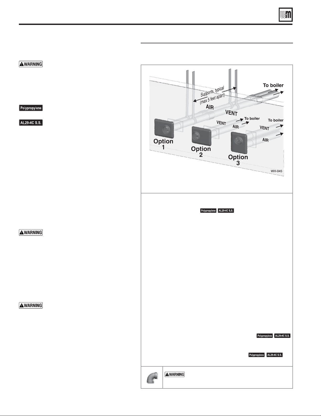
Part number 550-100-260/0520
32
ECO
®
Tec
GAS-FIRED WATER BOILER – 80/110/150/199 BOILER MANUAL
DIRECT VENT — Sidewall with W-M vent/air plate
Use only the vent materials and kits
listed in Figure 27, page 23 . Provide pipe
adapters if specifi ed.
1. Locate the termination such that the total air piping
and vent piping from the boiler to the termination
will not exceed the maximum length given in
Figure 26, page 22 .
For polypropylene applications, See
venting and air piping notes on page 21 .
For AL29-4C vent pipe applications,
See venting and air piping notes on
page 21 .
1. The vent/air cap must be installed as shown in
Figure 41, page 33 .
2. The termination must comply with clearances and
limitations shown in Figure 28, page 25 .
3. Locate the termination so it is not likely to be
damaged by foreign objects, such as stones or balls,
or subject to buildup of leaves or sediment.
1. When terminating multiple boilers, terminate each
vent/air connection as described in this manual.
All vent pipes and air inlets must
terminate at the same height to avoid
possibility of severe personal injury,
death or substantial property damage.
2. Place wall penetrations to obtain minimum
clearance as shown in for U. S. installations. For
Canadian installations, provide clearances required
by CSA B149.1 or B149.2 Installation Code and a
ULC S636 compliant vent kit.
3. The air inlet of a boiler is part of a direct vent
connection. It is not classifi ed as a forced air intake
with regard to spacing from adjacent boiler vents.
For terminations of other appliances,
provide at least the clearance shown. The
installation must also comply with the
manual for the other appliances.
— W-M sidewall vent/air plate
Read and follow all instructions in this manual.
See notices at left and page 21 .
Install the boiler in a location that allows proper routing of all vent
and air piping to the selected sidewall location.
Make sure the selected sidewall termination location complies with
Figure 28, page 25 . (Multiple boiler sidewall plates must also comply
with Figure 39, page 33 .)
Use only the vent materials listed in Figure 27, page 23 . Provide pipe
adapters where required.
Vent piping and air piping lengths must not exceed the values shown
in
Figure 26, page 22 .
Prepare the sidewall penetrations and secure the sidewall plates as
instructed in this section. See “Install Weil-McLain vent/air cap” on
page 33 .
The Weil-McLain plate termination must be installed before piping
from the boiler to the termination.
Install vent and air piping between the boiler and the vent/air
termination plate. Slope horizontal piping downward toward the boiler
at least 1/4 inch per foot. See page 27 for general guidelines.
Install pipe supports every 5 feet on both the horizontal and vertical
runs, or per vent pipe manufacturer’s instructions.
See notices at left and page 21 .
Install a hanger support within 6 inches of any upturn in the piping,
or per vent pipe manufacturer’s instructions.
See
notices at left and
page 21 .
— DO NOT use short radius elbows for vent or
air piping. Boiler performance could be affected.
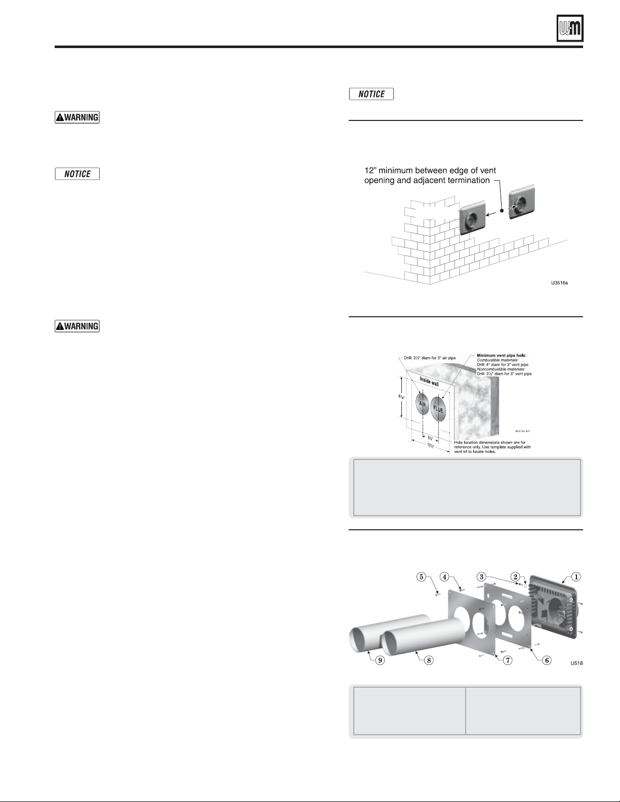
Part number 550-100-260/0520
33
ECO
®
Tec
GAS-FIRED WATER BOILER – 80/110/150/199 BOILER MANUAL
Vent/air pipes and W-M vent/air plate can be
oriented in any of the configurations shown
in Figure 38, page 32.
Adjacent terminations — OUTSIDE
VIEW — clearance from air inlet to
exhaust from another appliance
DIRECT VENT — Sidewall with W-M vent/air plate (continued)
Hole preparation in wall — INSIDE
VIEW (use template provided)
1 Inside wall
2 Drill: 3½" diameter for 3" air pipe; locate using template provided
3 For combustible materials, drill: 4" diameter for 3" vent pipe
For noncombustible materials, drill 3½" diameter for 3" vent pipe
Locate opening using template provided
4 Drill mounting screw holes using template provided
Termination assembly — INSIDE VIEW
Weil-McLain vent/air cap and plates
1 Vent termination (3")
2 Lock washer, #10 (4)
3 Sheet metal screw, #10 x ½" (4)
4 Plastic wall anchor (8)
5 Sheet metal screw, #10 x 1¼" (8)
6 Outer mounting plate
7 Inner mounting plate
8 Vent pipe (butt to screen in
termination)
9 Air pipe (butt to stops in termination)
— Use adapters if using other than 3-inch
PVC or CPVC. This is required for different materials
(polypropylene or AL29-4C stainless steel) or if using
2-inch pipe.
The inside and outside cover plates are stamped to
identify the exhaust (vent) and intake (air) openings.
Make sure to orient the plates correctly.
1. Locate termination opening and avoid obstructions:
a. Use the template supplied with the termination kit.
b. Locate the template on the outside building surface where the
penetration is to be made.
c. Make sure there will be no obstructions that might prevent
proper placement of the termination.
d. Use the template to mark the locations for the four mounting
holes, flue pipe and air pipe. Level the template with a level.
For the Weil-McLain plate, the template must be level to
ensure the flue and air pipe will be side-to-side, as shown
in Figure 40. Failure to comply could result in severe
personal injury, death or substantial property damage.
e. Cut holes in the wall as shown in Figure 40, using the location
marks made with the template. For best results, use a small-
diameter, long drill bit to drill centering holes for the flue and
air pipe openings. Then drill the large openings from both the
inside and outside.
f. The flue pipe and air pipe may be run through a rectangular
cutout (as marked on the template) in lieu of two separate
holes if desired.
2. Drill holes for the screws or plastic anchors to secure the outside
plate. Install the outside plate and mount the termination on the
plate (temporarily).
a. Cut the flue pipe so the extension through the wall will cause
the vent pipe to fully extend into the termination socket.
b. Cut the air pipe so the extension through the wall will butt the
air pipe against the stops inside the termination.
c. Temporarily slide the flue and air pipes through the opening(s).
Slide the inside wall plate over the two pipes and into position
on the inside wall.
d. Position the inside plate so the flue pipe and air pipe slope
downward slightly toward the boiler (1/4" per foot).
e. Mark the four (4) mounting holes for the plate.
f. Remove the vent and air pipe, drill the four mounting holes,
and mount the inside plate.
3. Test fit the vent/air termination on the vent pipe. Make sure the
vent pipe fully penetrates the termination socket and the air pipe
butts against the interior stops.
4. Apply silicon RTV sealant to the interior of the vent termination
and slide onto vent pipe. Rotate slightly to spread the silicon to
ensure a tight seal around the vent pipe.
5. Secure the termination in place using the four (4) #10 x ½" sheet
metal screws and lock washers (see Figure 41).
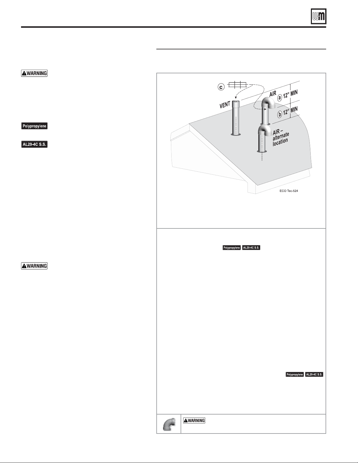
Separate pipes vertical termination
IS AT LEAST 12 inches below vent outlet.
IS AT LEAST 12 inches above roof or snow line.
Read and follow all instructions in this manual.
See notices at left and page 21 .
Install the boiler in a location that allows proper routing of all vent
and air piping to the selected sidewall location.
Make sure the selected vertical termination location complies with
Figure 28, page 25 . (Multiple boiler terminations must also comply
with Figure 43, page 35 .)
Use only the vent materials listed in Figure 27, page 23 . Provide pipe
adapters where required. Vent piping and air piping lengths must not
exceed the values shown in
Figure 26, page 22 .
Prepare the vertical penetrations and secure penetration components
as instructed in this section. See “Prepare roof penetrations” on page 35
and “Termination and fi ttings” on page 35 .
The air piping must terminate in a 180-degree return bend or
as shown above. The vent piping must terminate in a
as shown above.
Install vent and air piping between the boiler and the vertical
terminations. Slope horizontal piping downward toward the boiler at
least 1/4 inch per foot. Install pipe supports every 5 feet on both the
horizontal and vertical runs. Install a hanger support within 6 inches
of any upturn in the piping. See
page 27 for general guidelines. Also
comply with vent pipe manufacturer’s instructions.
See notices at left and page 21 .
Insert the vent and air piping through the vertical penetrations and
secure the termination fi ttings.
Maintain clearances shown above. Vent and air terminations must be
fi tted with a bird screen as shown.
— DO NOT use short radius elbows for vent or
air piping. Boiler performance could be affected.
Part number 550-100-260/0520
34
ECO
®
Tec
GAS-FIRED WATER BOILER – 80/110/150/199 BOILER MANUAL
Use only the vent materials and kits
listed in Figure 27, page 23 . Provide pipe
adapters if specifi ed.
1. Locate the terminations such that the total air
piping and vent piping from the boiler to the
termination will not exceed the maximum length
given in Figure 26, page 22 .
For polypropylene applications, See
venting and air piping notes on page 21 .
For AL29-4C vent pipe applications,
See venting and air piping notes on
page 21 .
1. The air and vent terminations must be installed as
shown in Figure 42 .
2. The terminations must comply with clearances and
limitations shown in Figure 28, page 25 .
3. Locate the terminations so they are not likely to be
damaged by foreign objects, such as stones or balls,
or subject to buildup of leaves or sediment.
1. When terminating multiple boilers, terminate each
vent/air connection as described in this manual.
Terminate all vent pipes at the same
height and all air pipes at the same height
to avoid possibility of severe personal
injury, death or substantial property
damage.
2. Place roof penetrations to obtain minimum
clearance of 12 inches between edge of air intake
elbow and adjacent vent pipe of another boiler
for U. S. installations (see Figure 43, page 35 ). For
Canadian installations, provide clearances required
by CSA B149.1 or B149.2 Installation Code and a
ULC S636 compliant vent kit.
3. The air inlet of a boiler is part of a direct vent
connection. It is not classifi ed as a forced air intake
with regard to spacing from adjacent boiler vents.
DIRECT VENT — Vertical with separate pipes
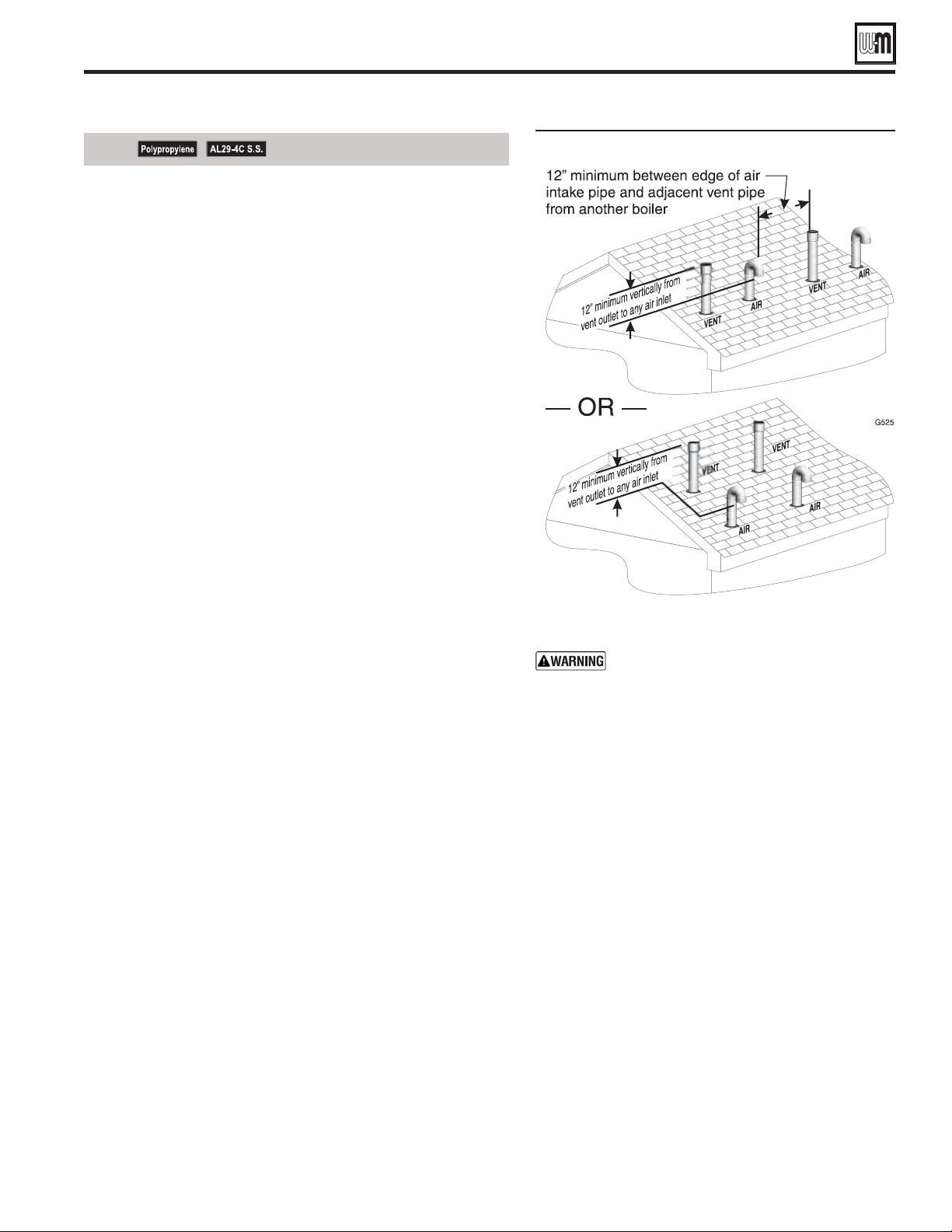
Terminations for multiple boilers
Also maintain maximum distances between
the vent and air pipes for each boiler as shown
in Figure 31, page 28 .
See notices on previous page.
Part number 550-100-260/0520
35
ECO
®
Tec
GAS-FIRED WATER BOILER – 80/110/150/199 BOILER MANUAL
1. Air pipe penetration:
a. Cut a hole for the air pipe. Size the air pipe hole as close as
desired to the air pipe outside diameter.
2. Vent pipe penetration:
a. Cut a hole for the vent pipe. For either combustible or
noncombustible construction, size the vent pipe hole at least
0.4" larger than the vent pipe diameter.
b. Insert a corrosion resistant metal thimble in the vent pipe hole.
3. Space the air and vent holes
no closer than the minimum spacings
shown in Figure 43 .
4. Follow all local codes and vent pipe manufacturer’s instructions
for isolation of vent pipe when passing through fl oors, ceilings
and roofs.
5. Provide fl ashing and sealing boots sized for the vent pipe and air
pipe. Follow all vent pipe manufacturer’s instructions.
1. Prepare the vent termination elbow and the air termination elbow
( Figure 42, page 34 ) by inserting bird screens. Bird screens must be
purchased separately. See the parts list at the end of this manual
for part numbers.
2. The air piping must terminate in a down-turned 180-degree return
bend as shown in Figure 42, page 34 . The edge of the air inlet elbow
must be at least 12 inches above the roof or snow line.
3. The vent piping must terminate in an up-turned coupling as shown
in Figure 42, page 34 . The top of the coupling must be at least 12
inches above the air intake in order to avoid recirculation of fl ue
products into the combustion air stream.
4. Maintain the required dimensions of the fi nished termination
piping as shown in Figure 42, page 34 .
5. Do not extend exposed vent pipe outside of building more than
shown in this document. Condensate could freeze and block vent
pipe.
DIRECT VENT — Vertical with separate pipes (continued)
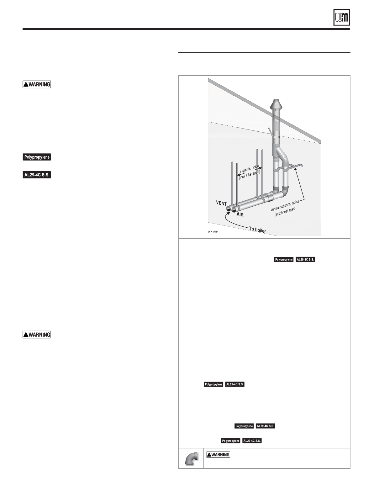
Part number 550-100-260/0520
36
ECO
®
Tec
GAS-FIRED WATER BOILER – 80/110/150/199 BOILER MANUAL
1. The concentric termination kit must be purchased
separately.
Use only the vent materials and kits listed in
Figure 27, page 23 . Provide pipe adapters if
specifi ed.
2. Locate the termination such that the total air piping and
vent piping from the boiler to the termination will not
exceed the maximum length given in Figure 26, page 22 .
3. This termination requires a 45-degree elbow that is not
supplied with the termination kit. The maximum vent/
air pipe lengths include allowance for this elbow.
For polypropylene applications, See venting
and air piping notes on page 21 .
For AL29-4C vent pipe applications,
See venting and air piping notes on page 21 .
Locate the concentric vent/air termination using the
following guidelines:
1. The concentric vent/air assembly must terminate as
shown in Figure 46, page 37
2. The termination must comply with the clearances and
limitations shown in Figure 28, page 25 .
3. Locate the termination so it is not likely to be damaged
by foreign objects, such as stones or balls, or subject to
buildup of leaves or sediment.
4. For Canadian installations, follow requirements of CSA
B149.1 or B149.2 Installation Code and a ULC S636
compliant vent kit.
1. When terminating multiple boilers, install the concentric
vent/air termination assemblies as described in this
manual.
All vent outlets must terminate at the same
height to avoid possibility of severe personal
injury, death or substantial property damage.
2. Place roof penetrations to obtain minimum clearance
of 12 inches between the edges of adjacent vent pipes
of other boilers for U. S. installations (see Figure 45 ).
3. For Canadian installations, provide clearances
required by CSA B149.1 or B149.2 Installation Code
and a ULC S636 compliant vent kit.
4. The air inlet of a boiler is part of a direct vent connection.
It is not classifi ed as a forced air intake with regard to
spacing from adjacent boiler vents.
1. Roof penetration hole:
a. Cut a clearance hole to clear the termination outside
diameter as prescribed in the kit instructions.
b. Insert a corrosion resistant metal thimble in the
vent pipe hole.
— Concentric vertical
Read and follow all instructions in this manual.
See notices at
left and page 21 .
Install the boiler in a location that allows proper routing of all
vent and air piping to the selected sidewall location.
Make sure the selected vertical termination location complies with
Figure 28, page 25 . (Multiple boiler concentric terminations must
also comply with Figure 45, page 37 .)
Use only the vent materials listed in Figure 27, page 23 . Provide
pipe adapters where required.
Vent piping and air piping lengths must not exceed the values
shown in
Figure 26, page 22 .
The concentric termination must be assembled and installed
before piping from the boiler to the termination.
Prepare the vertical penetration(s) — assemble the concentric
termination kit and secure the penetration components as
instructed in this section. Provide the supports indicated and
mount the termination assembly. See “Prepare roof penetrations”
on page 36 and “Mount concentric termination” on page 37 .
See notices at left and page 21 .
Install vent and air piping between the boiler and the concentric
vent/air termination. Slope horizontal piping downward toward
the boiler at least 1/4 inch per foot. See page 27 for general
guidelines.
Install pipe supports every 5 feet on both the horizontal and
vertical runs.
See notices at left and page 21 .
Install a hanger support within 6 inches of any upturn in the
piping.
See notices at left and page 21 .
— DO NOT use short radius elbows for vent
or air piping. Boiler performance could be affected.
DIRECT VENT — Vertical concentric
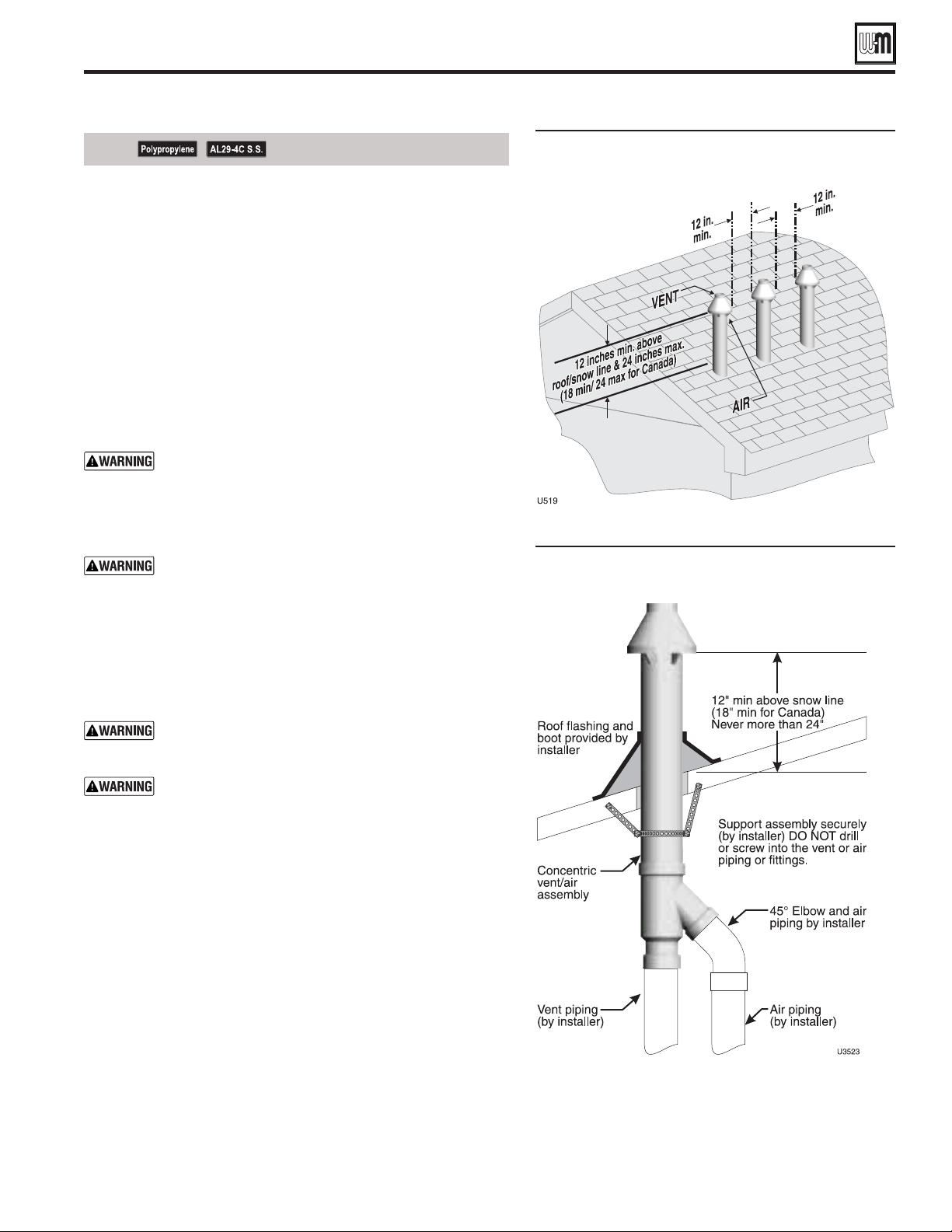
Vertical termination — 3" PVC
concentric — single or multiple boilers
3" PVC concentric termination
supports
See notices on previous page.
Part number 550-100-260/0520
37
ECO
®
Tec
GAS-FIRED WATER BOILER – 80/110/150/199 BOILER MANUAL
2. Follow all local codes for isolation of vent pipe when passing
through floors, ceilings and roofs.
3. Provide flashing and sealing boots sized for the concentric
termination outside diameter.
1. Assemble the vent termination as described for concentric
terminations, on page 40.
2. Mount the termination as shown in Figure 46.
3. Support the concentric vent/air termination at the roof penetration
as shown in Figure 46 or per concentric kit instructions.
The supports/bracing used must support the termination
assembly to prevent vertical slippage or sideways movement.
The clamps used on the outside of the termination pipe must
not cut into the pipe or contain sharp edges that could cause
a crack to form.
The vent and air piping must be securely supported,
and must not rest its weight on the boiler fittings. DO
NOT drill or screw into either the vent pipe or air pipe.
Failure to properly support the vent and air piping could
result in vent piping damage, resulting in possible severe
personal injury, death or substantial property damage.
When inserting the partially-assembled termination
kit through the roof penetration, wrap plastic or other
protection over the end of the exposed assembly to
prevent debris from entering the pipes. If the air passages
become blocked, the boiler will not operate. Once the rain
cap has been cemented to the assembly, there is no way
to correct the problem. The assembly would have to be
replaced if it were cut to be removed and cleaned. Altering
the assembly in any way could result in severe personal
injury or death due to toxic flue product emissions.
If using AL29-4C stainless vent pipe, use the vent pipe
manufacturer’s PVC adapter if connecting to a PVC
concentric vent attachment.
Do not connect any other appliance to the vent pipe or
multiple boilers to a common vent pipe.
4. After the assembly has been positioned in the roof opening and
all supports have been attached, install a bird screen (purchased
separately if not included with the kit) and rain cap as follows:
a. Place the bird screen on the end of the inner pipe as in
Figure 50, page 40, or per kit instructions for polypropylene kits.
b. Cement the rain cap in place.
DIRECT VENT — Vertical concentric (continued)
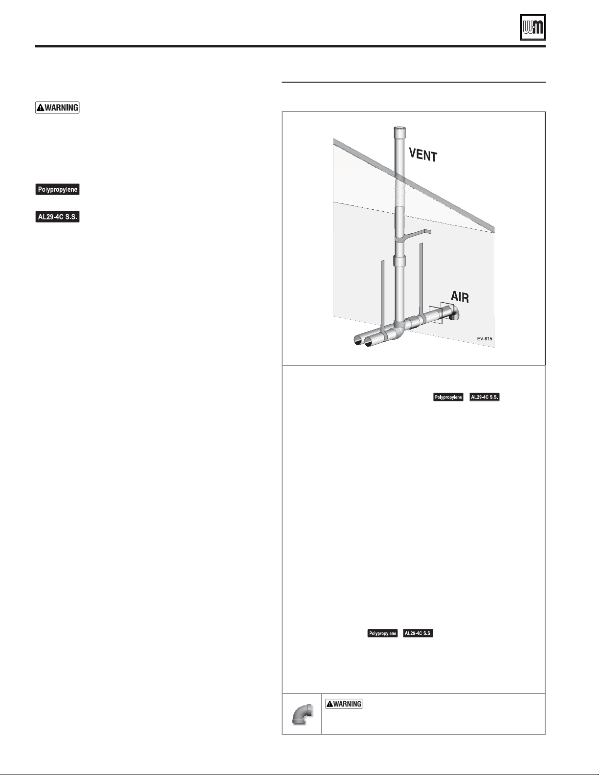
Part number 550-100-260/0520
38
ECO
®
Tec
GAS-FIRED WATER BOILER – 80/110/150/199 BOILER MANUAL
DIRECT VENT — Vertical vent /sidewall air
— Vertical vent/sidewall
air
Use only the vent materials and kits listed in
Figure 23, page 24. Provide pipe adapters if
specifi ed.
1. Locate the terminations such that the total air piping
and vent piping from the boiler to the termination
will not exceed the maximum length given in
Figure 22, page 23.
For polypropylene applications, See venting
and air piping notes on page 21 .
For AL29-4C vent pipe applications,
See venting and air piping notes on page 21 .
2. For 3” to 2” transitions, must use appropriate vent
material. For polypropylene or stainless steel must use
approved suppliers transitions.
1. Vent pipe penetration:
a. Cut a hole for the vent pipe. For either combustible
or noncombustible construction, size the vent pipe
hole at least 0.4” larger than the vent pipe diameter.
b. Insert a galvanized metal thimble in the vent pipe
hole.
2. Follow all local codes for isolation of vent pipe when
passing through fl oors, ceilings and roofs.
3. Provide fl ashing and sealing boots sized for the vent
pipe and air pipe.
1. Prepare the vent termination coupling by inserting a
bird screen. Bird screens must be purchased separately.
See the parts list at the end of this manual for part
numbers.
2. Maintain the required dimensions of the finished
termination piping as shown in Figure 48 .
1. When terminating multiple ECO
Tec boilers, terminate
each vent/air connection as described in this section.
2. Place adjacent terminations at least 6 inches apart.
3. For Canadian installations, provide clearances required
by Natural Gas and Propane Installation
CAN/CSA
B149.1 or B149.2 Installation Code.
Read and follow all instructions in this manual.
See notices
at left and page 21 .
Install the boiler in a location that allows proper routing of all
vent and air piping to the selected locations.
Make sure the selected vertical termination location complies
with Figure 28, page 25 .
Use only the vent materials listed in Figure 27, page 23 . Provide
pipe adapters where required. Vent piping and air piping lengths
must not exceed the values shown in Figure 26, page 22 .
Prepare the vertical penetration (vent) and sidewall penetration
(air) and secure penetration components as instructed in this
section.
The air piping must terminate in a 90-degree
as shown above. The vent piping must terminate in a
as shown above.
Install vent and air piping between the boiler and the air and
vent terminations. Slope horizontal piping downward toward
the boiler at least 1/4 inch per foot. Install pipe supports every
5 feet on both the horizontal and vertical runs. Install a hanger
support within 6 inches of any upturn in the piping. See page 39
for general guidelines. Also comply with vent pipe manufacturer’s
instructions.
See notices at left and page 21 .
Insert the vent and air piping through the penetrations and
secure the termination fi ttings.
Maintain clearances shown in this section. Vent and air
terminations must be fi tted with bird screens as shown.
— DO NOT use short radius elbows
for vent or air piping. Boiler performance could be
affected.
Part number 550-100-260/0520
39
ECO
®
Tec
GAS-FIRED WATER BOILER – 80/110/150/199 BOILER MANUAL
DIRECT VENT — Vertical vent /sidewall air (continued)
Figure 48 Vent termination (through the roof) for
direct vent: vertical vent / sidewall air
Figure 49 Sidewall air inlet (termination) for
direct vent: vertical vent / sidewall air
Determine location for air inlet elbow
1. The air inlet of an ECO
Tec boiler is part of a direct vent
connection. It is not classified as a forced air intake with regard
to spacing from adjacent appliance terminations.
2. Locate the air inlet elbow (termination) using the following
guidelines.
3. The air piping must terminate in a down-turned elbow as shown
in Figure 49.
a. Apply the configuration on the left side of Figure 49 unless
the terminations would fail to meet minimum clearance to
grade or snow line.
b. Apply the configuration on the right side of Figure 49 when
the terminations need to be raised higher to meet clearance
to grade or snow line.
c. The air pipe may run up the side of the building, as shown.
The vent and air pipes must be secured with braces, and all
clearances and lengths must be maintained. Space braces no
further than 24 inches apart.
4. You must consider the surroundings when terminating the air
connection:
a. Make sure there are no obstructions for air flow. DO NOT
locate the termination where plants could grow and cause
obstruction to air flow.
b. Do not locate the terminations where wind eddies could affect
performance or cause recirculation with exhaust from other
appliances, such as inside building corners, near adjacent
buildings or surfaces, window wells, stairwells, alcoves,
courtyards or other recessed areas.
c. Locate the air inlet termination at least 12 inches below and 12
inches horizontally from any appliance or building vent outlet.
5. Locate terminations so they are not likely to be damaged by
foreign objects, such as stones or balls, or subject to buildup of
leaves or sediment.
Multiple air terminations
1. When terminating multiple ECO
Tec boiler air connections,
terminate each air connection as described in this manual.
2. Place wall penetrations to obtain minimum clearances as
instructed in this manual.
3. Place adjacent air inlets for multiple ECO
Tec boilers at least
6 inches apart.
4. For Canadian installations, provide clearances required by Natural
Gas and Propane Installation
CAN/CSA
B149.1 or B149.2
Installation Code.
Prepare wall penetrations
1. Air pipe penetration:
a. Cut a hole for the air pipe. Size the air pipe hole as close as
desired to the air pipe outside diameter.
2. Seal exterior openings thoroughly with exterior caulk.
Termination and fittings
1. Prepare the air termination elbow (Figure 49) by inserting a bird
screen. Bird screens must be purchased separately. See the parts
list at the end of this manual for part numbers.
2. Use metal plates (by installer) at inside and outside penetrations
using the method shown in Figure 28, page 29.
If extending the air pipe out from the wall, install a
coupling on each pipe. Mount the piping with the
coupling flush with the outer plate.
Part number 550-100-260/0520
40
ECO
®
Tec
GAS-FIRED WATER BOILER – 80/110/150/199 BOILER MANUAL
Concentric termination, typical (sidewall or vertical)
concentric termination assembly — DO
NOT attach the rain cap until the termination
has been inserted through the roof or wall and
all supports have been installed. See LEGEND
at right. See kit instructions for details of
polypropylene kits.
1. Follow all instructions provided with the concentric
termination kit. The following are general guidelines
for information only
2. See Figure 50 for the typical assembly of a concentric
termination assembly.
3. Prepare the bird screen, Item 4 (purchase separately if
not included with the kit). Cut the bird screen to size
if required. If the bird screen must be trimmed, cut the
bird screen to fit the outside diameter of the PVC inner
pipe supplied with the termination kit.
4. Partially assemble the vent termination kit in the
sequence shown in Figure 50, or per the concentric kit
instructions.
install the rain cap and bird screen
until the assembly has been inserted through
the roof (or sidewall) and all supports have
been installed. Follow instructions to cover
the end of the assembly with plastic before
inserting through the roof penetration to
prevent debris from blocking the air passages.
If necessary, you can shorten the lengths
of the inner and outer pipes for a shorter
finished assembly. But you must ensure the
pipes butt correctly at both ends. Failure to
properly assemble the concentric termination
can result in flue gas recirculation, causing
possible severe personal injury or death.
For polypropylene applications, See venting
and air piping notes on page 21.
For AL29-4C vent pipe applications, See
venting and air piping notes on page 21.
1 Inner PVC pipe (vent)
2 Outer PVC pipe (air)
3 Rain cap
4 Bird screen
5 Y fitting
6 Finished assembly
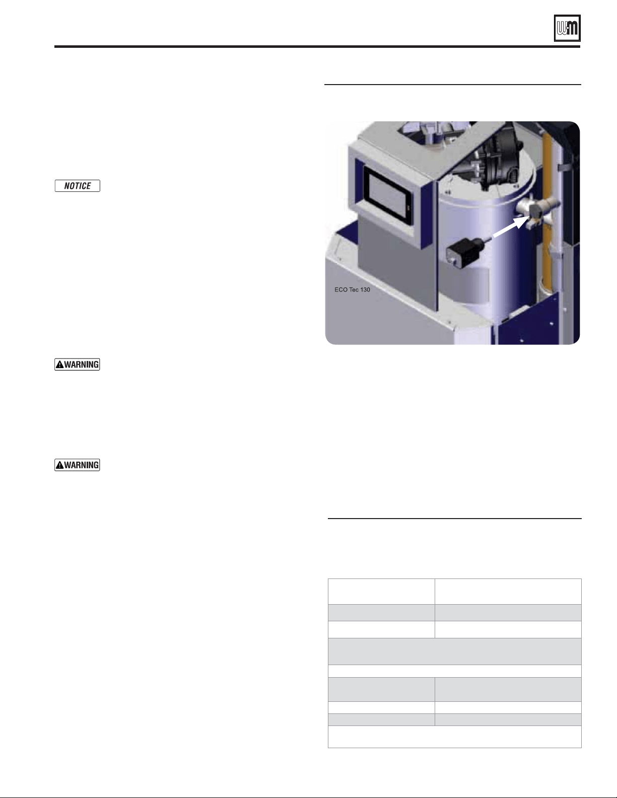
Part number 550-100-260/0520
41
ECO
®
Tec
GAS-FIRED WATER BOILER – 80/110/150/199 BOILER MANUAL
General piping information
We recommend installing 1" NPT piping unions on boiler
outlet and return to facilitate future service. Pipe unions are
Not included with the boiler.
The control uses temperature sensors to provide
both high limit protection and modulating
temperature control.
. Some codes/
jurisdictions may require additional external
controls for high limit protection.
Some jurisdictions require an additional high temperature
limit. Consult local requirements for other codes/standards to
determine if needed.
1. If required, install a manual reset high temperature limit
constructed to prevent a temperature setting above 200°F
in Boiler In piping between boiler and isolation valve. (Note
that the control operating limit function shuts the boiler
down at 195°F, or lower if set to a lower value.)
— If the heating
system includes circuits that require lower
temperature water (radiant slab circuits, for
example) as well as higher temperature circuits,
it is recommended to protect low-temperature
circuits with limit controls that are wired to the
control external limit circuit terminals. Please note
that a combi model installed in a low temperature
system is a multi-temperature system.
Low temperature materials — If using temperature-
limited materials (such as PEX tubing) in system
piping, it is recommended to protect the system
with limit controls that are wired to the controls
external limit circuit.
2. See instructions beginning on page 58 for wiring information.
3. If using a manual reset limit control or wiring in the manual
reset circuit, set control boiler limit at least 20°F less than the
external manual reset limit (i.e., set control no higher than
180°F for a 200°F external limit, for example).
1. A separate low water cutoff is required. See NOTICE above
regarding the inherent protection provided by the Control
module. A low water cut-off is to be supplied by the installer.
2. A 3/4" female NPT port is included within the internal boiler
piping and it is recommended you install a low water cut off
at this location, see Figure 51 .
3. Use a low water cutoff designed for water installations.
Electrode probe-type is recommended.
See Replacement parts section at the end of this manual
for the Weil-McLain low water cut-off kit. When using
kit, ensure extra wire length is neatly bundled with zip ties
and away from internal components.
4. For additional Limit controls wiring, see Field wiring
instructions beginning on page 58 .
Install boiler water piping
Boiler Models System header
80/110 1" or larger
150/199 1¼" or larger
Recommendations are based on a 20°F temperature drop
through the system.
Suggested maximum load per zone
Copper pipe and
baseboard size
Maximum recommended
feet of baseboard
¾" 67
1" 104
Size zone circulators to handle the required fl ow and head
loss for each zone.
Use backfl ow preventer in the cold water supply piping if required
by local codes.
System/zone pipe sizing
For residential space heating applications (other than radiant
heating or unit heaters) ONLY, you can use the sizing suggestions
in Figure 52 .
LWCO 3/4" female NPT port location
Suggested pipe sizing for system headers
and zone piping — RESIDENTIAL with
baseboard, convectors or cast iron
radiators ONLY (20°F temperature rise)
Part number 550-100-260/0520
42
ECO
®
Tec
GAS-FIRED WATER BOILER – 80/110/150/199 BOILER MANUAL
Install boiler water piping (continued)
General Piping Information
Head Loss through Boiler – Tables 4 and 5
Table 5 ECO
Tec Combi
Flow
(GPM)
80/110 C 150 C 199 C
Head Loss
(ft. w.c.)
Head Loss
(ft. w.c.)
Head Loss
(ft. w.c.)
4 0.2 -- --
6 1.6 1.0 --
8 3.1 3.3 3.3
10 4.6 5.6 5.6
12 6.1 7.8 7.9
14 -- 10.1 10.2
16 -- 12.4 12.5
18 -- -- 14.9
20 -- -- 17.2
Table 4 ECO
Tec Heat Only
Flow
(GPM)
80/110 HO 150 HO 199 HO
Head Loss
(ft. w.c.)
Head Loss
(ft. w.c.)
Head Loss
(ft. w.c.)
6 1.0 –– ––
8 2.2 1.3 0.4
10 3.4 3.1 2.6
12 4.5 4.8 4.7
14 -- 6.6 6.8
16 -- 8.3 8.9
18 -- -- 11.0
20 -- -- 13.1
0.0
2.0
4.0
6.0
8.0
10.0
12.0
14.0
0 5 10 15 20
Head Loss (ft w.c.)
Flow (gpm)
Head Loss Through Boiler (Heat Only Unit)
80/110 HO
150 HO
199 HO
0.0
2.0
4.0
6.0
8.0
10.0
12.0
14.0
16.0
18.0
20.0
0 5 10 15 20
Head Loss (ft w.c.)
Flow (gpm)
Head Loss Through Boiler (Combi Unit)
80/110 Combi
150 Combi
199 Combi
Internal Circulator
This boiler is equipped with an internally installed Taco 0015e3 boiler circulator. In some piping systems, this circulator will provide
enough head for a direct connect system. See instructions starting on page 46 for Direct Connect System Piping. In all other cases,
this circulator will provide the proper boiler flow for a primary/secondary system piping. See instructions starting on page 50 for
Primary/Secondary System Piping.
The Taco 0015e3 is a variable speed, high-efficiency wet rotor circulator with an ECM permanent magnet motor that has three
different positions: LOW, MEDIUM, and HIGH. This circulator comes set at HIGH. This is the ideal setting for this boiler in most
cases. In some installations, the speed can be reduced, if the boiler temperature rise is smaller than the desired rise at the boiler’s
maximum input.
LED COLOR STATUS
ORANGE CIRCULATOR ON
FLASHING WHITE
AIR BOUND OR CAVITATION
RED BLOCKED
OFF CIRCULATOR OFF
Part number 550-100-260/0520
43
ECO
®
Tec
GAS-FIRED WATER BOILER – 80/110/150/199 BOILER MANUAL
If the boiler piping system is connected to heating coils located
in air handling units where there may be exposed to refrigerated
air circulation then it must be equipped with flow control valves
or other automatic means to prevent gravity circulation of the
boiler water during the cooling cycle.
see Figure 54, page 44.
1. Size piping for DHW inlet and outlet is 3/4” NPT.
2. In hard water areas – To prevent the formation of scale
on the inside of the plate DHW heat exchanger and other
components in the domestic hot water system, water with
hardness higher than 50 ppm Calcium Carbonate must be
treated with a “Water Softener” prior to entering the boiler.
Plugging of the domestic system by scaling or accumulation
of dirt is not the responsibility of Weil-McLain, and suitable
steps must be taken to avoid it.
3. The maximum domestic water pressure rating is 150 PSI
for all combi models, on the domestic pipes and internal
components.
4. A field supplied pressure relief valve that complies with
the standard for relief valves and automatic gas shut-off
devices for Hot Water Supply Systems, ANSI Z21.221
CSA4.4 - latest edition, is required to be installed at the
supply DHW connection-. This pressure relief valve
should be capable of at least the Maximum input of the
boiler model
*
and Maximum pressure Not exceeding
150 PSIG. The pressure relief valve’s discharge should be
per instructions in the Warning box, page 48. DO NOT
place any other type valve or shut-off device between the
relief valve and the boiler. The pressure relief valve must be
manually checked once a year to verify correct operation,
*
110 MBH, 150 MBH or 199 MBH, depending on the
boiler model).
5. Thermostatic Mixing Valve - An ASSE 1070 automatic
mixing valve for regulating domestic heating water must be
used to regulate the water temperature leaving the plate heat
exchanger. NOTE: the valve must be set to supply a domestic
water temperature of not more than 120 degrees F. It is the
responsibility of the installer to set the valve and remove or
lock the dial depending on valve capabilities.
6. Additional anti-scald devices may be installed at each hot
water faucet, bath and shower outlet.
7. DHW Filter (Installer Supplied): It is recommend to install
a 25 micron or lower domestic water filter in the cold water
line which feeds into the combi boiler for domestic hot water
production. This filter will protect the DHW flow sensor
and prolong the time between cleaning and overall life of
the brazed plate heat exchanger and flow sensor. In harsh
water conditions a finer filter and/or water softener may
be required. Consult your local water quality professional.
Check Valve – A check valve must be field provided
and installed on the outlet of the mixing valve to
prevent reverse flow. Failure to prevent the backflow
will cause water to flow through the flow switch,
activating it, when the cold water draw has ended
and the water pressure increases.
8. Drain and Isolation Valves - Install drain and isolation valves
on the inlet and outlet of the DHW connections so that
the DHW heat exchanger can be flushed and cleaned from
possible build-up caused by dirty or hard water, which is a
maintenance requirement. See page 52 for Weil-McLain’s
DHW Service Valve Kit installation and Figure 125, page 137
for kit part number.
9. Cleaning – refer to the installation manual maintenance
section for the proper cleaning procedure for the plate DHW
heat exchanger, and the required cleaning frequency.
Hot Water Can Scald!
Consumer Product Safety Commission and some
states recommend domestic hot water temperature of
130°F or less.
When installing an automatic mixing valve, selection
and installation must comply with valve manufacturer’s
recommendations and instructions.
Water heated to a temperature suitable for clothes
washing, dish washing and other sanitizing needs will
scald and cause injury.
Children, elderly, infirm or physically handicapped
persons are more likely to be injured by hot water. Never
leave them unattended in or near a bathtub, shower
or sink. Never allow small children to use a hot water
faucet or draw their own bath. If anyone using hot water
in the building fits this description, or if state laws or
local codes require certain water temperatures at hot
water faucets, take special precautions:
Install automatic mixing valve set according to those
standards.
Use lowest practical temperature setting.
Check water temperature immediately after first heating
cycle and after any adjustment.
Install boiler water piping (continued)
Domestic Water Piping – Combi Boiler
This boiler is NOT intended for connection with
a refrigeration system.
Studies have indicated that dangerous bacteria
can form in potable water distribution systems
if certain minimum water temperatures are not
maintained. Contact local health department for
more information.

Part number 550-100-260/0520
44
ECO
®
Tec
GAS-FIRED WATER BOILER – 80/110/150/199 BOILER MANUAL
Install boiler water piping (continued)
Domestic Piping - Brazed Plate Heat
Exchanger - Ports 2 and 4
Recirculation (if used)
Massachusetts code applications require
recirculation piping or heat-traced piping if the
distance from the water heater to the furthest fixture
exceeds 100 feet.
Other jurisdictions may also require. Check local
codes.
Maintaining domestic water
temperature in the supply piping
1. Recirculation is used to reduce wait time for water use, to
minimize hot water and energy waste caused during the waiting
period, and to prevent degradation of the Boiler In water
temperature. ASPE recommends recirculation when the distance
from the water heater to the furthest fixture exceeds 100 feet or
the time lag for hot water to reach a fixture(s) exceeds 30 seconds.
2. Consult local codes and American Society of Plumbing Engineers
(ASPE) Domestic Water Heating Design Manual - latest edition,
for further information.
Recirculation pump (Figure 55, page 45, Item 8)
1. Circulator size must achieve a flow rate of 0.5 GPM or greater to
activate the boiler, the thermostatic mixing valve will vary the
flow rate through the boiler and must be considered when sizing
the circulator.
2. Minimum flow rates of the thermostatic mixing valve must
be maintained.
3. The circulator cannot run continuously as bypass through
the anti-scald mixing valve will eventually allow the water
temperature in the piping to climb to the water heater
temperature during draw periods, (heating performance would
be reduced based off of priority switching and priority timers).
4. An aquastat, timer, or occupancy sensor must be used
with recirculation pump to prevent continuous flow. Some
recirculation pumps may have smart controls that are suitable
as well.
5. See Figure 55, page 45 for recommend recirculation pump
piping diagram. This piping strategy is for a dedicated DHW
return pipe.
Aquastat (Figure 55, page 45, Item 9)
1. An Aquastat is recommended to be used when a recirculation
pump is installed. The aquastat is used to control the on-off
position of the recirculating circulator. Aquastat is set 5° to
10° lower than mixed water outlet of the anti-scald mixing
valve (Item 7).
2. A timer may be used in addition to the aquastat to limit the
time of day recirculation is used.
Domestic water supplied to fixtures that could pose
an injury hazard due to high temperature, such as
showers and faucets, should be equipped with a
temperature regulating device, such as an anti-scald
mixing valve.
Check valves (Figure 55, page 45, Item 4)
1. Assure the flow of water in one direction.
2. Each check valve functions as follows:
a. Prevent bypass in the event of pressure drop.
b. Prevents thermal siphoning of hot water to the cold water
supply.
c. Prevents flow of cold water to the tempered water supply.
A draw of tempered water will not result in flow of cold
water into the return loop.
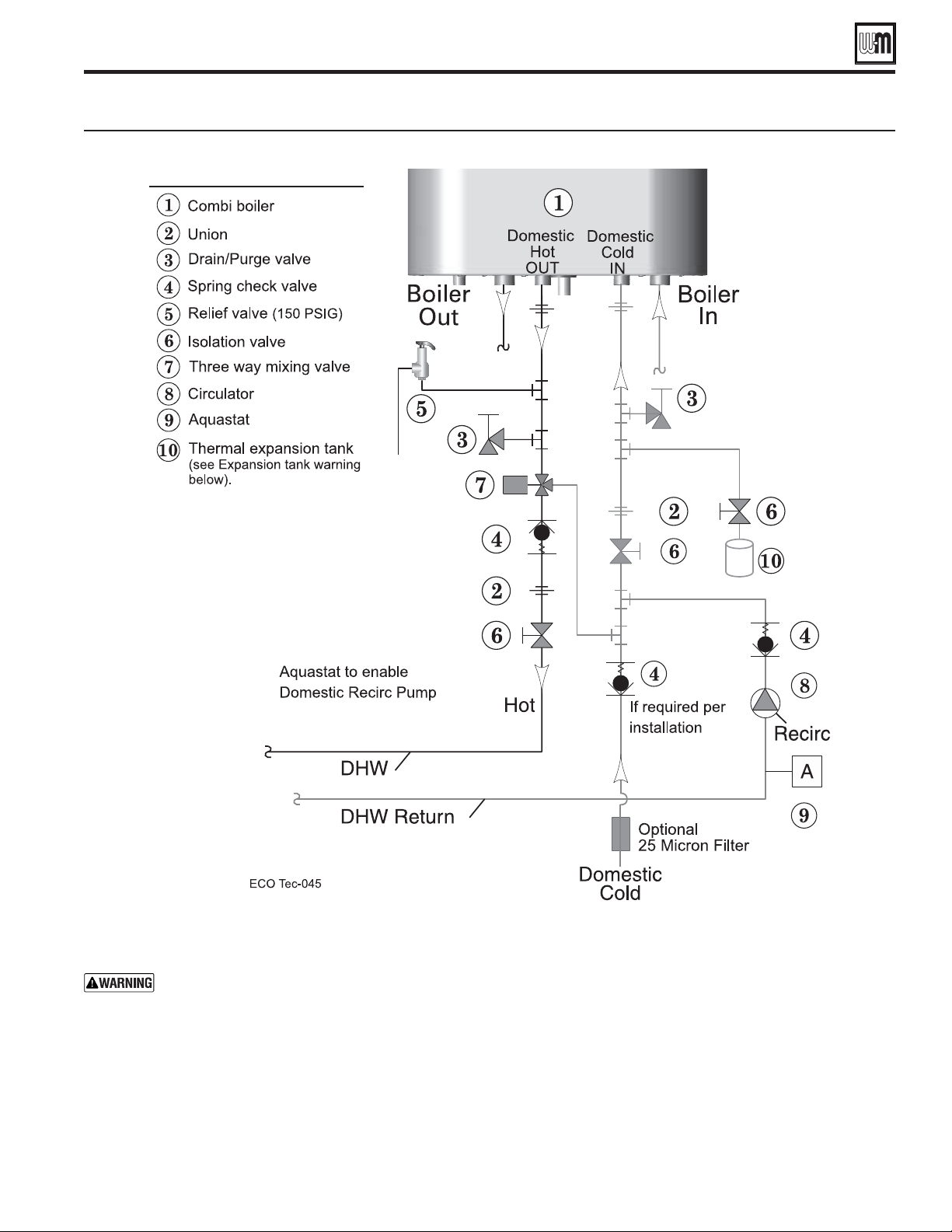
Part number 550-100-260/0520
45
ECO
®
Tec
GAS-FIRED WATER BOILER – 80/110/150/199 BOILER MANUAL
Install boiler water piping (continued)
Recirculation piping diagram (if used)
Expansion tank (Figure 55, Item 10)
THERMAL EXPANSION TANK — If a backflow preventer, check
valve, or pressure reducing valve is piped on cold water inlet of water
heater, you must install an expansion tank on cold water supply line
to prevent normal thermal expansion from repeatedly forcing open T&P relief
valve.
The T&P relief valve is not intended for constant duty, such as relief of pressure
due to repeated normal system expansion. Refer to expansion tank manufacturer’s
instructions for proper sizing.
Failure to comply could result in severe personal injury, death or substantial
property damage.
Part number 550-100-260/0520
46
ECO
®
Tec
GAS-FIRED WATER BOILER – 80/110/150/199 BOILER MANUAL
System water piping methods
It is recommended, but not required, to use primary/
secondary piping to the boiler. Using primary/
secondary piping will provide the most accurate
desired system heating temperature.
1. Read the NOTICES and guidelines beginning on page
46 to determine if the system is eligible for this piping strategy.
2. If eligible, reference suggested piping layouts on pages 47
and 48.
3. Use primary/secondary piping if system ineligible.
Using primary/secondary piping will provide the most accurate
desired system heating temperature. Reference suggested piping
layouts on pages 50-55.
Some installations can be piped in numerous
other ways that will work equally as well as the
suggestions here.
Verify the application will work:
Direct connect will only work with the ECO
Tec
80/110/150 models.
The minimum temperature rise across the heat
exchanger is 20°F during high fire operation. The
factory installed circulator will provide between
a 20° and 35°F temperature rise across the heat
exchanger depending on boiler model (System
head loss must be less than what is listed in Table
6 , page 47). If the temperature drop across the
heat exchanger is lower than 20°F during high fire,
the flow rate will need to be reduced until 20° is
achieved.
Systems zoning with circulators must use primary/
secondary piping layout using guidelines starting
on page 50.
Verify that the internal circulator will provide enough head to the
system, see Table 6 , page 47.
If the internal circulator will not provide enough head for the
system, then direct connect piping can not be used. The system
will have to be set up for primary/secondary piping (see page 50).
1. To determine whether direct connection will provide suitable
flow for the intended application
2. The minimum temperature rise across the heat exchanger
is 20°F during high fire operation. Using flow rates higher
than the maximum is NOT RECOMMENDED. The factory
installed circulator will provide the temperature rise given
in Table 2, page 47 during high fire operation if the system
head matches the corresponding table value.
3. Design zoning to ensure minimum flow rate is maintained
under any call for heat condition that could see full input
rate (High Fire).
Use a primary/secondary piping layout if the total flow through
the heat exchanger will be higher than the maximum.
Any system zoned with zone valves must include a
by-pass pressure regulator. Failure to comply may
reduce pump life.
The boiler circulator is factory-installed in the boiler.
remove or relocate the boiler circulator.
The boiler circulator is selected to ensure adequate
flow through the boiler.
Failure to comply could result in unreliable
performance and nuisance shut downs from
insufficient flow.
If replacing included circulator with a replacement
Taco model, replace only with Taco Model 0015e3
circulator. Set to Max.
Expansion tank location
Figure 56 and Figure 58 show typical installation of the system
expansion tank. It is highly recommended that you locate the air
separator and expansion tank as shown in the suggested piping
drawings on page 47 and page 48.
Ensure that the expansion tank size will handle boiler and
system water volume and temperature. See tank manufacturer’s
instructions and ratings for details. Additional tanks may be added
to the system if needed to handle the expansion. These tanks may
be installed by connecting to tees in the system piping.
Undersized expansion tanks cause system water to
be lost from the relief valve and makeup water to be
added through the fill valve. Eventual boiler failure
can result due to excessive make-up water addition.
Always locate the cold-water fill connection at the
expansion tank. Never locate this elsewhere.
Diaphragm- or bladder-type tank:
Refer to Figure 56 for suggested piping when using a diaphragm-
or bladder-type expansion tank.
Install an automatic air vent on top of the air separator, per
separator manufacturer’s instructions.
Diaphragm- or bladder-type expansion tank—
Calculated cold fill pressure should equal tank
air charge pressure. Always check pressure and
charge tank with tank removed from system to
be sure reading is accurate. Boiler relief valve
is set for 30 PSIG. Operating pressure of system,
after temperature expansion above cold fill pressure,
should not exceed 24 PSIG to avoid weeping of relief
valve.
Direct Connect System Piping - Single Boiler System
80/110/150 Boilers only
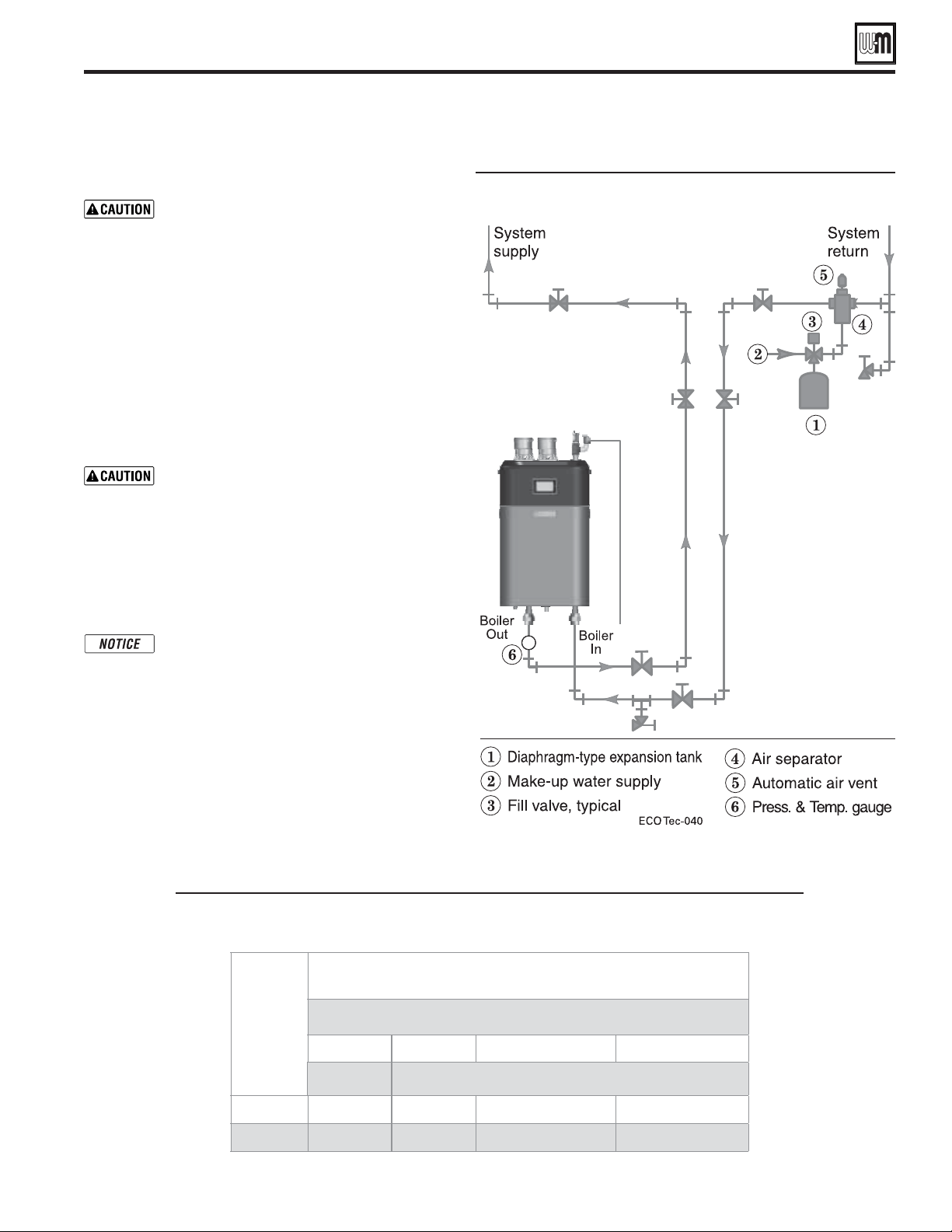
Part number 550-100-260/0520
47
ECO
®
Tec
GAS-FIRED WATER BOILER – 80/110/150/199 BOILER MANUAL
Piping to diaphragm- (or bladder-) type expansion tank
Closed-type expansion tank:
DO NOT use a closed-type tank if connecting
to a water heater that is equipped with an
automatic air vent or if an automatic air vent
is incorporated into the system piping.
Figure 56 shows suggested piping when using a closed-
type expansion tank, in which the air is directly in contact
with tank water.
Connect piping (½" or ¾") from the air separator outlet to
the tank fitting. Slope any horizontal piping a minimum
of 1 inch per 5 feet of horizontal pipe.
Always use a tank fitting such as the B&G Tank-trol or Taco
Taco-trol (shown). The fitting reduces gravity flow of water
in the piping to the tank, avoids air bubbling through the
tank water, and provides the proper fill height in the tank
Correct all leaks in the system or tank piping.
Leaks allow air to escape from the system
and will cause water-logging of the tank.
This will result in water loss through the
boiler relief valve due to over-pressurization.
NEVER use an automatic air vent in a system
equipped with a closed-type expansion tank.
The air removed from the system will cause
water-logging of the expansion tank.
Closed-type expansion tank—Follow tank
manufacturer’s instructions for filling
the tank. Typical tank sizing provides for
approximately 12 PSIG when the tank
is filled to the normal level and system
water is cold. Note that boiler relief valve
is set for 30 PSIG. Operation pressure of
system, after temperature expansion above
cold fill pressure, should not exceed 24
PSIG to avoid weeping of relieve valve.
Direct Connect System Piping - Single Boiler System
80/110/150 Boilers only
Table 6
Boiler Pump Head
available to system
ECO
Tec
80-H 80-H 110-H (110-C) 150-H (150-C)
20° 30°
Ft. w.c. 6.6 12.7 9.1(4.6) 3.9(1.4)
GPM 7.2 4.8 6.5 9.0
Boiler Pump Head available to system
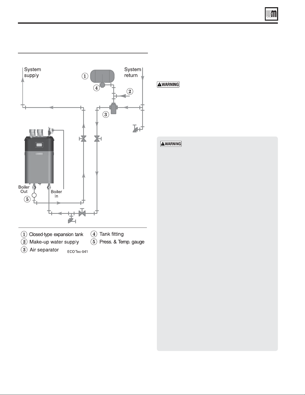
Part number 550-100-260/0520
48
ECO
®
Tec
GAS-FIRED WATER BOILER – 80/110/150/199 BOILER MANUAL
:
Install relief valve ONLY with the spindle
vertical, as shown in illustrations in this
manual.
Discharge line must be connected to relief
valve outlet and run to a safe place of disposal.
Terminate the discharge line in a manner that
will prevent possibility of severe burns or
property damage should the valve discharge.
Locate away from the top of the boiler.
Discharge line must be as short as possible
and be the same size as the valve discharge
connection throughout its entire length.
Discharge line must pitch downward from
the valve and terminate at least 6" above the
floor drain where any discharge will be clearly
visible.
The discharge line shall terminate plain, not
threaded, with a material serviceable for
temperatures of 375 °F or greater.
Do not pipe the discharge to any place where
freezing could occur.
No shutoff valve shall be installed between the
relief valve and boiler, or in the discharge line.
Do not plug or place any obstruction in the
discharge line.
Test the operation of the valve after filling and
pressurizing system by lifting the lever. Make
sure the valve discharges freely. If the valve fails
to operate correctly, replace it with a new relief
valve.
Failure to comply with the above guidelines
could result in failure of the relief valve to
operate, resulting in possibility of severe
personal injury, death or substantial property
damage.
Install relief valve
1. Install relief valve in a 3/4" street elbow along with a 3/4"
tee onto the top water pipe – Air elimination/relief valve
(Figure 8, page 13).
the boiler out. Connect the
relief valve only as shown in this manual. Ensure
relief valve is located above heat exchanger.
2. Pipe the relief valve only as shown, in the location shown.
3. Connect discharge piping to safe disposal location,
following guidelines in the WARNING below.
Piping to closed-type expansion tank
Direct Connect System Piping - Single Boiler System (continued)
80/110/150 Boilers only
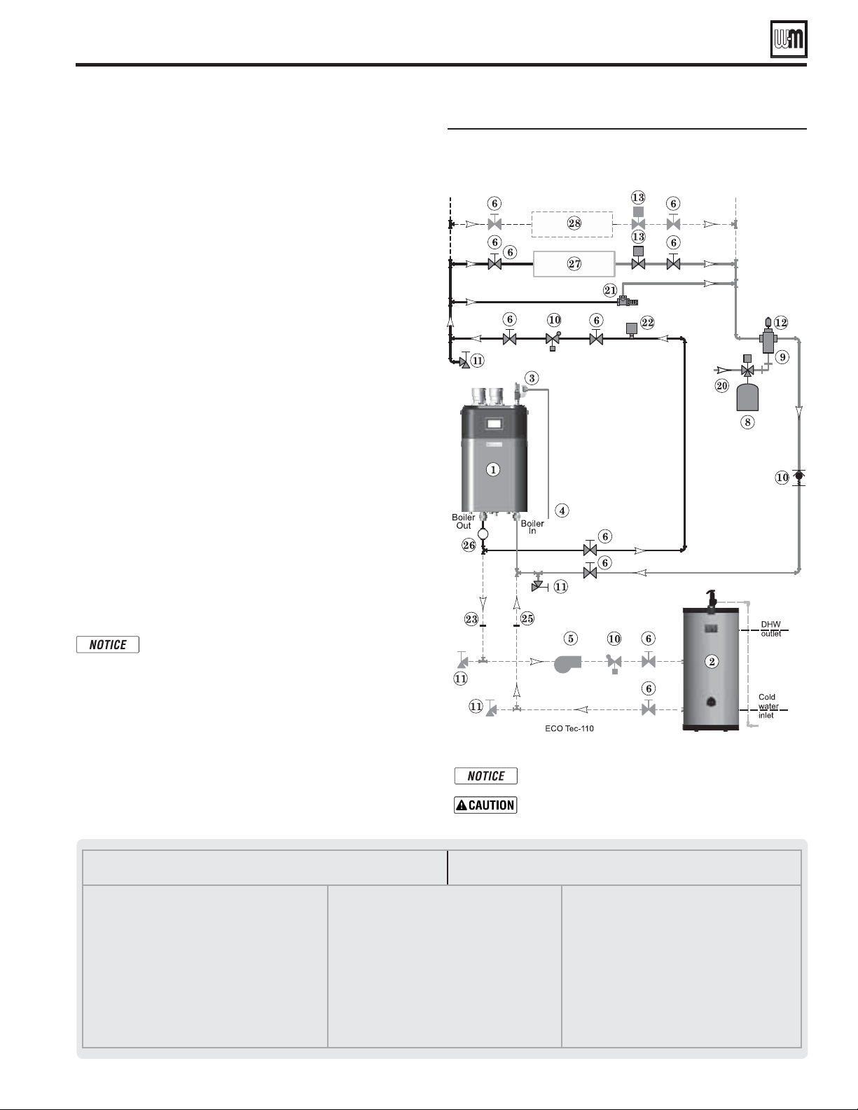
ECO
Tec 80/110/150 Zone valve zoning direct
connection (internal boiler circulator provides
flow for system
)
Part number 550-100-260/0520
49
ECO
®
Tec
GAS-FIRED WATER BOILER – 80/110/150/199 BOILER MANUAL
ZONE VALVE zoning – direct connection
(Shown with optional DHW piping)
See Figure59.
1. This configuration is for zone valve systems that qualify to
use direct connection piping based on the criteria on page 46
only. If system does not qualify, pipe using primary/secondary
piping. See pages 51-55 for piping suggestions and guidelines.
2. Systems zoned with zone valves MUST use a by-pass pressure
regulator (Taco 3196 or equivalent – Item 21) unless using
modulating type of circulator that has protection against
dead heading.
Expansion Tank required
1. Provide a system expansion tank following the guidelines on
page 46 or page 48.
2. DO NOT use a closed-type tank if connecting to a water
heater that is equipped with an automatic vent.
Domestic Hot Water (DHW) tank, if used
1.
DHW direct connection—Pipe from the near-boiler piping
to the DHW tank’s boiler connections as shown.
2. DHW as zone— A DHW tank can be connected as a zone
if a DHW tank is NOT already connected to the boiler. See
notices on page 149 to ensure compliance with the 2007
Energy Act. See Control section in this manual, page 84 to
change TARGET MODULATION SENSOR to System Supply
when system sensors are installed.
3. DHW Priority operation— Using Priority 1 for DHW
(default) will turn off lower priorities during DHW calls. The
MAX ON TIME setting can be adjusted to limit how long
this occurs. Use Priority 2 or 3 for DHW if DHW priority
is not desired.
Overriding the Outdoor Reset function by setting
control to DHW mode when system is intended
for space heating may violate Section 303 of the
2007 Energy Act. See page 149 for compliance
information and exemptions.
Controlling the circulators (Direct Connect only)
1. In a direct connect set-up, by default the internal circulator
will turn on for any configured heating call or DHW call.
2. If an Indirect tank is used, as in Figure 59, a secondary
circulator will have to be configured to turn on when the
indirect tank input is active.
Connect zone valve end switches to Priority 2 input.
Use isolation relays if connecting 3-wire zone valve end
switches to the input.
.
This is a common legend for all piping diagrams.
Not all Items listed appear in every figure.
1 ECO
Tec boiler
2 Indirect Water Heater, if used
3 Relief valve, supplied with boiler, field piped — MUST
be piped to Boiler In connection — see page 13 for
information
4 Relief valve piping to drain — see page 48
5 DHW circulator
6 Isolation valves
7 System circulator
8 Expansion tank, diaphragm type, if used
9 Air separator
10 Spring check valves
11 Purge/drain valves
(one drain valve shipped loose with boiler)
12 Auto air vent
13 Zone valves
14 Primary/secondary connection (tees no more than 12
inches apart)
15 Expansion tank, closed type, if used (some chiller
systems may use a diaphragm-type expansion tank)
16 Water chiller
17 Check valve
18 Y-strainer
19 Balancing valve
20 Make-up water supply – Use applicable codes to
determine if backflow preventers, pressure reducing
valves, and fill valves may be required
21 By-pass pressure regulator, REQUIRED for zone valve
systems unless other provision is made
22 High limit temperature control
23 DHW tank boiler water supply connection, when used
24 Zone circulator
25 DHW tank boiler water return connection, when used
26 Pressure/temperature gauge, supplied with boiler, field
piped
27 Heating circuits
28 Additional heating circuits, if any
Direct Connect System Piping - Single Boiler System (continued)
80/110/150 Boilers only
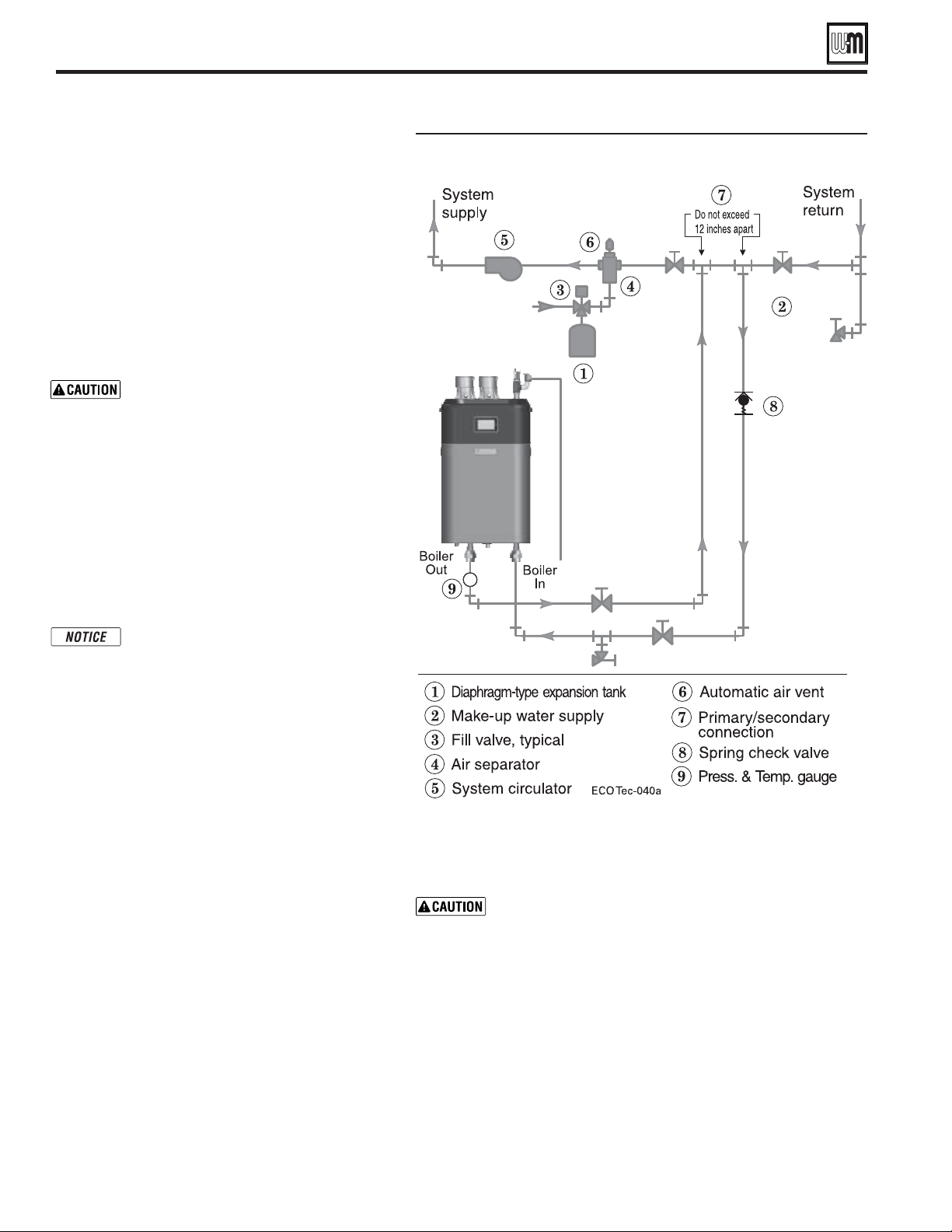
Piping to diaphragm (or bladder) expansion tank
Part number 550-100-260/0520
50
ECO
®
Tec
GAS-FIRED WATER BOILER – 80/110/150/199 BOILER MANUAL
Primary/Secondary System Piping - Single Boiler System
Expansion tank location
Figure 60 and Figure 61 show typical installation of the
system expansion tank. It is highly recommended that
you locate the air separator and expansion tank as shown
in the suggested piping drawings on pages 53-55.
Ensure that the expansion tank size will handle boiler
and system water volume and temperature. See tank
manufacturer’s instructions and ratings for details.
Additional tanks may be added to the system if needed
to handle the expansion. These tanks may be installed
by connecting to tees in the system piping.
Undersized expansion tanks cause system
water to be lost from the relief valve
and makeup water to be added through
the fill valve. Eventual boiler failure can
result due to excessive make-up water
addition. Always locate the cold-water ll
connection at the expansion tank. Never
locate this elsewhere.
Diaphragm- or bladder-type tank:
Refer to Figure 60 for suggested piping when using a
diaphragm- or bladder-type expansion tank.
Diaphragm- or bladder-type expansion
tank—Calculated cold fill pressure
should equal tank air charge pressure.
Always check pressure and charge tank
with tank removed from system to be sure
reading is accurate. Boiler relief valve is
set for 30 PSIG. Operating pressure of
system, after temperature expansion above
cold fill pressure, should not exceed 24
PSIG to avoid weeping of relief valve.
Install an automatic air vent on top of the air separator,
per separator manufacturer’s instructions.
Closed-type expansion tank
DO NOT use a closed-type tank if connecting to a water
heater that is equipped with an automatic air vent or if an
automatic air vent is incorporated into the system piping.
Figure 61, page 51 shows suggested piping when using a closed-type
expansion tank, in which the air is directly in contact with tank water.
Connect piping (½" or ¾") from the air separator outlet to the tank fitting.
Slope any horizontal piping a minimum of 1 inch per 5 feet of horizontal pipe.
Always use a tank fitting such as the B&G Tank-trol or Taco Taco-trol. The
fitting reduces gravity flow of water in the piping to the tank, avoids air
bubbling through the tank water, and provides the proper fill height in the
tank. Continued on next page.

Part number 550-100-260/0520
51
ECO
®
Tec
GAS-FIRED WATER BOILER – 80/110/150/199 BOILER MANUAL
Primary/Secondary System Piping - Single Boiler System (continued)
Correct all leaks in the system or tank piping. Leaks
allow air to escape from the system and will cause
water-logging of the tank. This will result in water
loss through the boiler relief valve due to over-
pressurization. NEVER use an automatic air vent in
a system equipped with a closed-type expansion tank.
The air removed from the system will cause water-
logging of the expansion tank.
Closed-type expansion tank—Follow tank
manufacturer’s instructions for filling the tank.
Typical tank sizing provides for approximately 12
PSIG when the tank is filled to the normal level and
system water is cold. Note that boiler relief valve is
set for 30 PSIG. Operation pressure of system, after
temperature expansion above cold fill pressure,
should not exceed 24 PSIG to avoid weeping of relieve
valve.
Piping to closed-type expansion tank
:
Install relief valve ONLY with the spindle
vertical, as shown in illustrations in this
manual.
Discharge line must be connected to relief
valve outlet and run to a safe place of
disposal. Terminate the discharge line in a
manner that will prevent possibility of severe
burns or property damage should the valve
discharge. Locate away from the top of the
boiler.
Discharge line must be as short as possible
and be the same size as the valve discharge
connection throughout its entire length.
Discharge line must pitch downward from
the valve and terminate at least 6" above
the floor drain where any discharge will be
clearly visible.
The discharge line shall terminate plain, not
threaded, with a material serviceable for
temperatures of 375°F or greater.
Do not pipe the discharge to any place where
freezing could occur.
No shutoff valve shall be installed between
the relief valve and boiler, or in the discharge
line. Do not plug or place any obstruction
in the discharge line.
Test the operation of the valve after filling and
pressurizing system by lifting the lever. Make
sure the valve discharges freely. If the valve fails
to operate correctly, replace it with a new relief
valve.
Failure to comply with the above guidelines
could result in failure of the relief valve
to operate, resulting in possibility of
severe personal injury, death or substantial
property damage.
Install relief valve
1. Install relief valve in a 3/4" street elbow along with a 3/4"
tee onto the top water pipe – Air elimination/relief valve
(Figure 8, page 13).
the boiler out. Connect the
relief valve only as shown in this manual. Ensure
relief valve is located above heat exchanger.
2. Pipe the relief valve only as shown, in the location shown.
3. Connect discharge piping to safe disposal location,
following guidelines in the below.
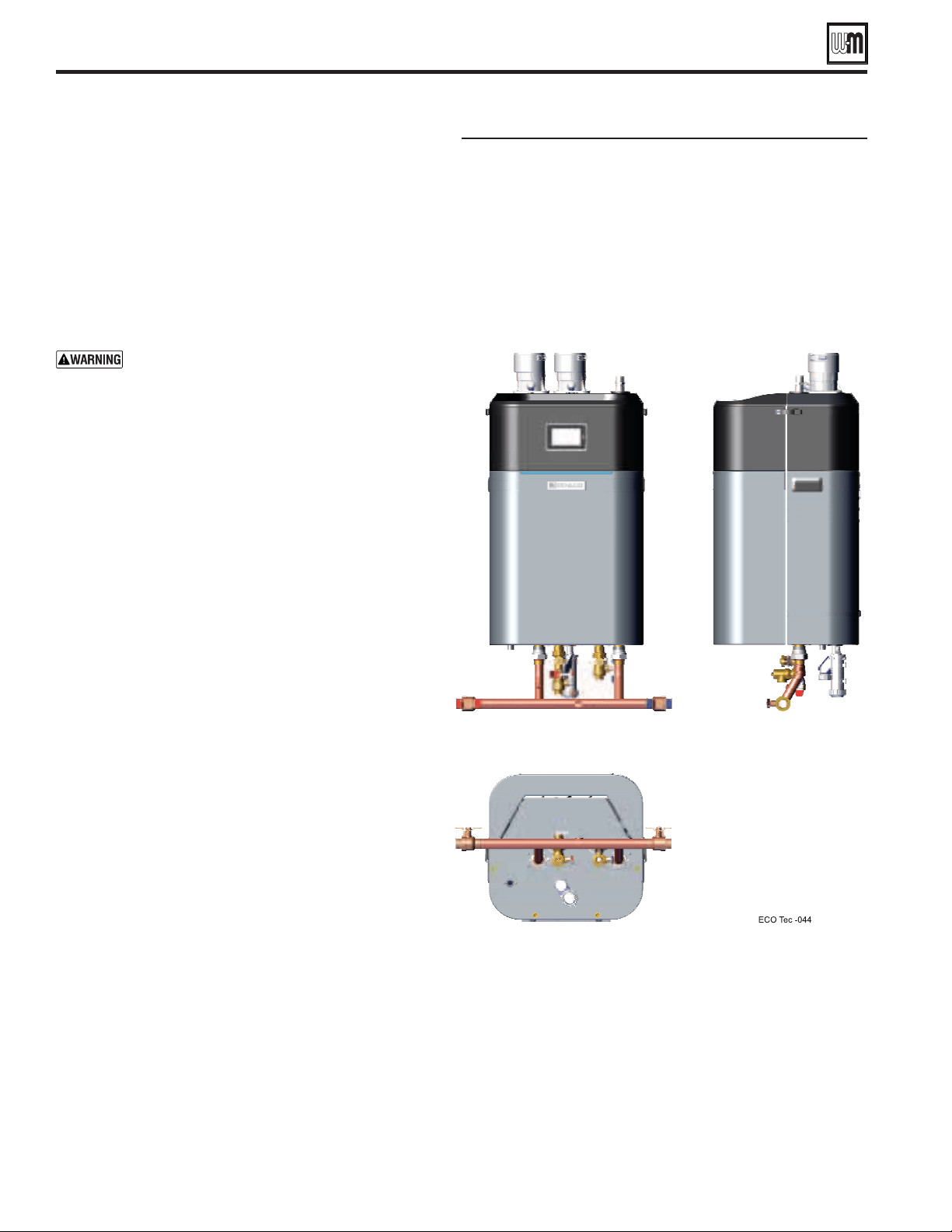
Part number 550-100-260/0520
52
ECO
®
Tec
GAS-FIRED WATER BOILER – 80/110/150/199 BOILER MANUAL
Primary/Secondary System Piping - Single Boiler System (continued)
System water piping methods
Connect boiler to system only as shown in Figure 60, page 50
and Figure 61, page 51. The primary/secondary piping shown
ensures the boiler loop will have sufficient flow.
The boiler circulator is factory-installed in the boiler as
shown in this manual. The boiler circulator is selected to
ensure adequate flow through the boiler loop.
relocate or use the boiler circulator
in any way other than the ones shown in this
manual.
Failure to comply could result in unreliable
performance and nuisance shut downs from
insufficient flow.
Install a system circulator or zone circulators as shown in the
piping diagrams in the Primary/Secondary System Piping
section in this manual. These circulators must be supplied
by the installer.
Size circulators based on the flow rate required to achieve
the temperature change you needed. You can closely estimate
temperature rise (or drop) through a circuit by using the
following formula, where TD is temperature rise (or drop),
FLOW is flow rate (in gpm), and BTUH is the heat load for
the circuit:
=
:
1. Consider a system loop for a system with total heating
load equal to 210,000 Btuh. The desired temperature
drop through the system piping is 20°F. Then the
required flow rate is:
=
=
1. The circulator must be capable of delivering the required
flow against the head loss that will occur in the piping.
2. Determine the pipe size needed and the resultant head
loss using accepted engineering methods.
Easy Up Manifold and DHW Service Valves
options
1. The ECO
Tec
Easy Up Manifold comes as a separate kit.
See Miscellaneous service parts and kits section at the end
of this manual for ordering information.
2. See separate instructions for the ECO
Tec
Easy Up Manifold
Weil-McLain website for suggested guidelines to determine how
to use and setup.
1. The ECO
Tec
DHW Service Valves comes as a separate kit, as well.
See Miscellaneous service parts and kits section at the end
of this manual for ordering information.
2. See separate instructions for the ECO
Tec
DHW Service Valves
Weil-McLain website for suggested guidelines to determine how
to use and setup.
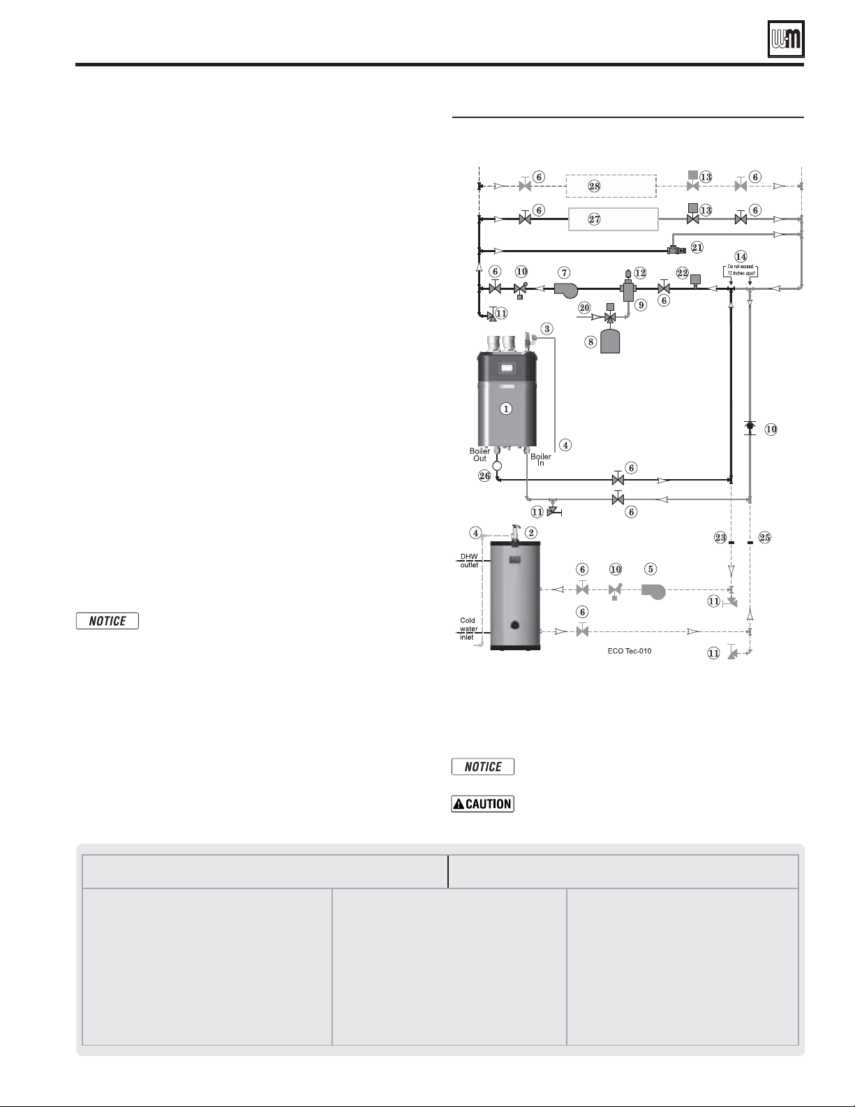
Zone valve zoning — primary/secondary
connection — a system circulator is required
Part number 550-100-260/0520
53
ECO
®
Tec
GAS-FIRED WATER BOILER – 80/110/150/199 BOILER MANUAL
ZONE VALVE zoning – primary/secondary
(Shown with optional DHW piping) See Figure63.
1. This configuration is for zone valve systems using a boiler loop
connected as a secondary circuit off of a primary system loop.
Systems whose flow characteristics do not comply with those
listed in Direct Connect System Piping must pipe the boiler loop
as a secondary circuit as show.
2. Systems zoned with zone valves MUST use a by-pass pressure regulator
(Taco 3196 or equivalent – Item 21) unless using modulating type of
circulator that has protection against dead heading.
3. Install a system circulator (supplied by installer) capable of
delivering the proper flow and head as shown.
Expansion Tank required
1. Provide a system expansion tank following the guidelines on
page 50 or 51.
2. DO NOT use a closed-type tank if connecting to a water heater
that is equipped with an automatic vent.
Domestic Hot Water (DHW) tank, if used
1. DHW direct connection—Pipe from the near-boiler piping to
the DHW tank’s boiler connections as shown.
2. DHW as zone— A DHW tank can be connected as a zone if a
DHW tank is NOT already connected to the boiler. See notices on
page 149 to ensure compliance with the 2007 Energy Act. See Control
section in this manual, page 84 to change TARGET MODULATION
SENSOR to System Supply when system sensors are installed.
3. DHW Priority operation— Using Priority 1 for DHW (default)
will turn off lower priorities during DHW calls. The MAX ON
TIME setting can be adjusted to limit how long this occurs.
Use Priority 2 or 3 for DHW if DHW priority is not desired.
For Combi models use INPUT2/PRIORITY 2 for the Indirect
DHW systems.
Overriding the Outdoor Reset function by setting
control to DHW mode when system is intended for
space heating may violate Section 303 of the 2007
Energy Act. See page 149 for compliance information
and exemptions.
Controlling the circulators
1. The Control, for Heat only models, can control up to five
circulators (boiler circulator and four others.) For Combi
models, the control can control up to three circulators (boiler
circulator and two others.) Refer to Field wiring, beginning on
page 58, for instructions on wiring to circulators.
2. The factory default settings are not configured. Each input
correlates to its respective circulator output. For DHW Priority
applications, wire aquastat to Input 1 and assign to Priority 1.
See Field wiring instructions, beginning on page 58, for details.
For Combi models use INPUT2/PRIORITY 2 for the Indirect
DHW systems.
3. The boiler and zone valves can also be operated by an external
zone valve controller or an equivalent wiring strategy.
Connect zone valve end switches to Priority 2 input.
Connect system circulator to Circ. 2 output.
Use isolation relays if connecting 3-wire zone valve
end switches to the input.
Primary/Secondary System Piping - Single Boiler System (continued
.
This is a common legend for all piping diagrams.
Not all Items listed appear in every figure.
1 ECO
Tec boiler
2 Indirect Water Heater, if used
3 Relief valve, supplied with boiler, field piped — MUST be
piped to Boiler In connection — see page 13 for information
4 Relief valve piping to drain — see page 51
5 DHW circulator
6 Isolation valves
7 System circulator
8 Expansion tank, diaphragm type, if used
9 Air separator
10 Spring check valves
11 Purge/drain valves
(one drain valve shipped loose with boiler)
12 Auto air vent
13 Zone valves
14 Primary/secondary connection (tees no more than 12
inches apart)
15 Expansion tank, closed type, if used (some chiller systems
may use a diaphragm-type expansion tank)
16 Water chiller
17 Check valve
18 Y-strainer
19 Balancing valve
20 Make-up water supply – Use applicable codes to determine
if backflow preventers, pressure reducing valves, and fill
valves may be required
21 By-pass pressure regulator, REQUIRED for zone valve
systems unless other provision is made
22 High limit temperature control
(If used)
23 DHW tank boiler water supply connection, when used
24 Zone circulator
25 DHW tank boiler water return connection, when used
26 Pressure/temperature gauge, supplied with boiler, field
piped
27 Heating circuits
28 Additional heating circuits, if any

Primary/Secondary System piping (continued)
Circulator zoning plus optional DHW piping
Part number 550-100-260/0520
54
ECO
®
Tec
GAS-FIRED WATER BOILER – 80/110/150/199 BOILER MANUAL
.
This is a common legend for all piping diagrams.
Not all Items listed appear in every figure.
1 ECO
Tec boiler
2 Indirect Water Heater, if used
3 Relief valve, supplied with boiler, field piped — MUST
be piped to Boiler In connection — see page 13 for
information
4 Relief valve piping to drain — see page 51
5 DHW circulator
6 Isolation valves
7 System circulator
8 Expansion tank, diaphragm type, if used
9 Air separator
10 Spring check valves
11 Purge/drain valves
(one drain valve shipped loose with boiler)
12 Auto air vent
13 Zone valves
14 Primary/secondary connection (tees no more than 12
inches apart)
15 Expansion tank, closed type, if used (some chiller
systems may use a diaphragm-type expansion tank)
16 Water chiller
17 Check valve
18 Y-strainer
19 Balancing valve
20 Make-up water supply – Use applicable codes to
determine if backflow preventers, pressure reducing
valves, and fill valves may be required
21 By-pass pressure regulator, REQUIRED for zone valve
systems unless other provision is made
22 High limit temperature control (If used)
23 DHW tank boiler water supply connection, when used
24 Zone circulator
25 DHW tank boiler water return connection, when used
26 Pressure/temperature gauge, supplied with boiler, field
piped
27 Heating circuits
28 Additional heating circuits, if any
Circulator zoning – primary/secondary
(Shown with optional DHW piping)
See Figure64.
1. This configuration is for circulator-zoned systems using a
boiler loop connected as a secondary circuit off of a primary
system loop. Systems zoned with circulators must pipe the
boiler loop as a secondary circuit as show.
2. Install a separate circulator (supplied by installer) for each zone
capable of delivering the proper flow and head as shown.
Expansion Tank required
1. Provide a system expansion tank following the guidelines
on page 50 or 51.
2. DO NOT use a closed-type tank if connecting to a water
heater that is equipped with an automatic vent.
Domestic Hot Water (DHW) tank, if used
1.
DHW direct connection—Pipe from the near-boiler piping
to the DHW tank’s boiler connections as shown.
2. DHW as zone— A DHW tank can be connected as a zone
if a DHW tank is NOT already connected to the boiler. See
notices on page 149 to ensure compliance with the 2007
Energy Act. See Control section in this manual, page 84 to
change TARGET MODULATION SENSOR to System Supply
when system sensors are installed.
3. DHW Priority operation— Using Priority 1 for DHW
(default) will turn off lower priorities during DHW calls. The
MAX ON TIME setting can be adjusted to limit how long
this occurs. Use Priority 2 or 3 for DHW if DHW priority
is not desired.
For Combi models use INPUT2/PRIORITY
2 for the Indirect DHW systems.
Overriding the Outdoor Reset function by setting
control to DHW mode when system is intended
for space heating may violate Section 303 of the
2007 Energy Act. See page 149 for compliance
information and exemptions.
Controlling the circulators
1. The Control, for Heat only models, can control up to five
circulators (boiler circulator and four others.) For Combi
models, the control can control up to three circulators (boiler
circulator and two others.) Refer to Field wiring, beginning
on page 58, for instructions on wiring to circulators.
2. The factory default settings are not configured. Each input
correlates to its respective circulator output. For DHW
Priority applications, wire aquastat to Input 1 and assign to Priority
1. See Field wiring instructions, beginning on page 58, for details.
For Combi models use INPUT2/PRIORITY 2 for the Indirect
DHW systems.
3. For more than 4-zones (Heat only models) or 2-zones (Combi
only models), use an external zone controller.
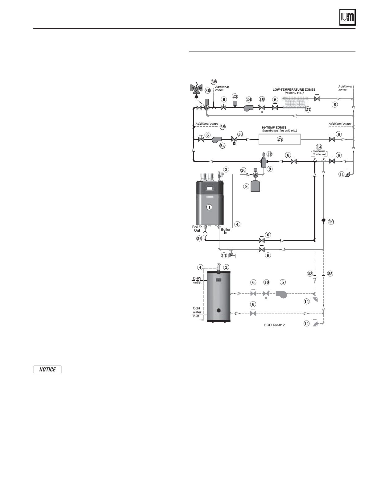
Circulator zoning with high- and low-
temperature heating zones
Primary/Secondary System piping (continued)
Part number 550-100-260/0520
55
ECO
®
Tec
GAS-FIRED WATER BOILER – 80/110/150/199 BOILER MANUAL
Circulator zoning – Multiple
temperature zones with primary/
secondary
(Shown with optional DHW piping)
See Figure65.
1. This configuration is for circulator-zoned systems with
high- and low-temperature heating zones using a boiler
loop connected as a secondary circuit off of a primary
system loop. Systems zoned with circulators must pipe
the boiler loop as a secondary circuit as shown.
2. Install a separate circulator (supplied by installer) for
each zone capable of delivering the proper flow and head
as shown.
Expansion Tank required
1. Provide a system expansion tank following the guidelines
on page 50 or 51.
2. DO NOT use a closed-type tank if connecting to a water
heater that is equipped with an automatic vent.
System setup and settings
1. Hi-temp emitters may be baseboards, radiators, fan coils,
or heat exchangers.
2. Add a mixing device (Figure 65, Item 30) to help ensure
supply water temperature will not exceed the maximum
allowable for the radiant system.
3. Heating zone supply water temperature settings should
be selected for the hi-temp zones. The mixing device
regulates supply temperature to the lower-temp zones.
Domestic Hot Water (DHW) tank, if used
1. DHW direct connection—Pipe from the near-boiler
piping to the DHW tank’s boiler connections as shown.
2. DHW as zone— A DHW tank can be connected as a zone
if a DHW tank is NOT already connected to the boiler. See
notices on page 149 to ensure compliance with the 2007
Energy Act. See Control section in this manual, page 84
to change TARGET MODULATION SENSOR to System
Supply when system sensors are installed.
3. DHW Priority operation— Using Priority 1 for DHW
(default) will turn off lower priorities during DHW calls.
The MAX ON TIME setting can be adjusted to limit how
long this occurs. Use Priority 2 or 3 for DHW if DHW
priority is not desired.
For Combi models use INPUT2/
PRIORITY 2 for the Indirect DHW systems.
Overriding the Outdoor Reset function by
setting control to DHW mode when system is
intended for space heating may violate Section
303 of the 2007 Energy Act. See page 149 for
compliance information and exemptions.
Controlling the circulators
1.
The Control, for Heat only models, can control up to
five circulators (boiler circulator and four others.) For
Combi models, the control can control up to three
circulators (boiler circulator and two others.)
Refer to
Field wiring, beginning on page 58, for instructions on
wiring to circulators.
2. The factory default settings are not configured. Each input
correlates to its respective circulator output. For DHW
Priority applications, wire aquastat to Input 1 and assign to Priority
1. See Field wiring instructions, beginning on page 58, for details.
For Combi models use INPUT2/PRIORITY 2 for the Indirect
DHW systems.
3. For more than 4-zones (Heat only models) or 2-zones (Combi
only models), use an external zone controller.
For Combi models
use INPUT2/PRIORITY 2 for the Indirect DHW systems.

Prepare condensate drain line assembly
Part number 550-100-260/0520
56
ECO
®
Tec
GAS-FIRED WATER BOILER – 80/110/150/199 BOILER MANUAL
The condensate trap, hose clamp, and
condensate drain line must be in place during
all operation. Make sure condensate trap
is securely attached to the condensate tube
outlet and that the condensate drain line
is securely attached to the condensate trap
outlet. Ensure all components are in good
conditioned and installed per this manual.
Failure to comply could result in server
personal injury, death or substantial property
damage
Prepare condensate drain line assembly
1. Remove the condensate trap kit from the bag assembly.
2. Remove the fl exile drain nut (Item 2) and tube gasket ring (Item
3) from the trap kit bag assembly.
3. Slide nut (Item 2) onto end of fl exible tube (Item 1).
4. Push the fl exible tube gasket ring (Item 3) onto the end of the
fl exible tube (Item 1) as shown in Figure 66 . The tube should
extend through the gasket about ¼ inch.
5. Insert the fl exible tube and gasket into the drain fi tting. When in
position, the offset edge of the gasket ring will rest on the shoulder
of the drain fi tting as shown in Figure 66 , detail 4.
6. Secure the fl exible tube in place by screwing on the nut, Item 2.
Finger tighten securely.
Install the condensate trap assembly
1. Remove pedestal front access panel (if installed as a fl oor standing
boiler), see Figure 67 .
2. Slide hose clamp onto condensate outlet tube and hold in place.
3. Slide the trap assembly into the boiler condensate outlet tube.
Tighten the hose clamp to secure the condensate trap in place.
4. If fl oor standing boiler, route hose through slot in side of boiler
pedestal.
Condensate drain system
1.
. The fl exible drain line will
fi t in a ¾" PVC coupling. Run minimum ½" PVC for the piping
to drain or condensate pump.
Use materials approved by the authority having
jurisdiction. In the absence of other authority, PVC and
CPVC pipe must comply with ASTM D1785, F441 or
D2665. Cement and primer must comply with ASTM
D2564 or F493. For Canada, use CSA or ULC certifi ed
PVC or CPVC pipe, fi ttings and cement.
2. Select a condensate pump (if used) that is approved for use with
condensing boilers and furnaces. The pump should have an
overfl ow switch to prevent property damage from condensate
spillage. The pump should have a minimum capacity of 2 GPH
for the ECO
Tec 80, 3 GPH for the ECO
Tec 110, 4 GPH for
the ECO
Tec 150 or 5 GPH for ECO
Tec 199.
3. When sizing condensate pumps, make sure to include the total
load of all appliances connected to it.
The condensate line must remain unobstructed,
allowing free fl ow of condensate. If condensate is
allowed to freeze in the line or if the line is obstructed
in any other manor, condensate can exit from the boiler
tee, resulting in potential water damage to property.
Condensate from the boiler will be slightly acidic
(typically with a pH from 3.2 to 4.5). Install a
neutralizing fi lter when draining into metal pipe and if
required by local codes. See Replacement parts section
at the end of this manual for the Weil-McLain kit.
Install condensate drain line & trap assembly
Slide Trap up into
Tube and secure by
tightening hose clamp
Condensate outlet tube and condensate trap
connection (front access panel
removed)
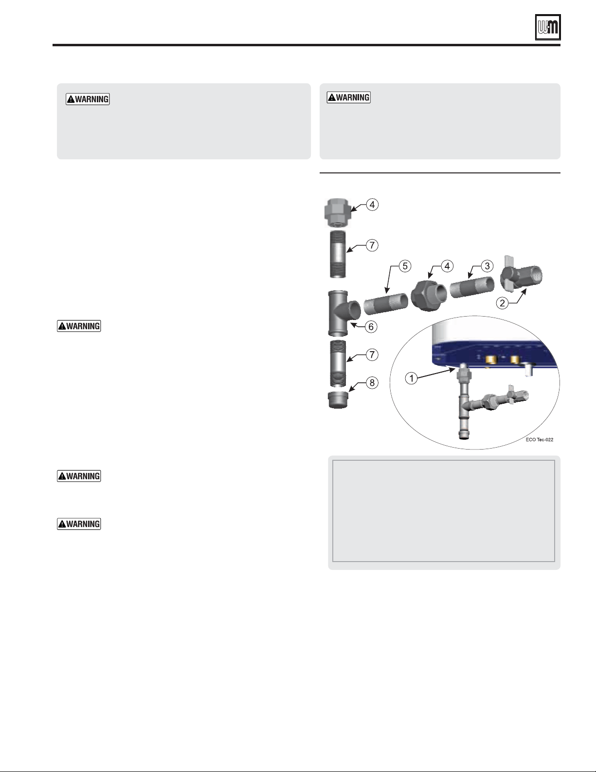
Connect gas supply piping
Part number 550-100-260/0520
57
ECO
®
Tec
GAS-FIRED WATER BOILER – 80/110/150/199 BOILER MANUAL
1 Boiler gas supply connection, ½" NPT male
2 Manual gas shut off valve, ½" NPT
3 Nipple, ½" NPT
4 Union, ½" NPT
5 Nipple, ½" NPT
6 Tee, ½" NPT
7 Nipple, ½" NPT x 4", for drip leg
8 Cap, ½" NPT
when tightening gas
piping at boiler, using one wrench to prevent
the boiler gas line connection from turning.
Failure to support the boiler gas connection
pipe to prevent it from turning could damage
gas line components.
Boilers are shipped ready to operate on natural
gas ONLY. You must install the propane mixer
(venturi) and orifice if the boiler will be
connected to propane. See page 14. Failure to
comply could result in severe personal injury,
death or substantial property damage.
Connecting gas supply piping
1. Remove jacket door and refer to Figure 68 to pipe gas to boiler.
a. Place a pipe wrench on the gas line inside the jacket
when tightening the gas line assembly to the boiler gas
connection (Item 1).
b. Install steel pipe fittings and factory-supplied manual gas
shut off valve as shown in Figure 68. All pipe fittings and
gas shut-off valve are supplied by the installer.
c. In Canada — The manual gas shut off valve (Item 2) must
be identified by the installer.
2. Use pipe dope compatible with propane gases. Apply sparingly
only to male threads of pipe joints so that pipe dope does not
block gas flow.
Failure to apply pipe dope as detailed above can
result in severe personal injury, death or substantial
property damage.
3. Connect gas supply piping to the ½" NPT manual gas shut
off valve (Item 2).
4. Support gas piping with hangers, not by boiler or its accessories.
5. Purge all air from gas supply piping.
6. Before placing boiler in operation, check boiler and its gas
connection for leaks.
a. During any pressure testing at less than 14" (355 mm)
w.c., close the gas shutoff valve and disconnect system gas
piping. At higher test pressures, disconnect boiler and gas
valve from gas supply piping.
Do not check for gas leaks with an open flame — use
bubble test. Failure to use bubble test or check for
gas leaks can cause severe personal injury, death or
substantial property damage.
DO NOT adjust or attempt to measure gas valve
outlet pressure. The gas valve is factory-set for the
correct outlet pressure. This setting is suitable for
natural gas and propane. Attempting to alter or
measure the gas valve outlet pressure could result
in damage to the valve, causing potential severe
personal injury, death or substantial property
damage.
See page 19 for gas line sizing information.
1. See Figure 93, page 102 for location of the gas inlet pressure
test port.
2. For natural gas or propane, the pressure required at gas valve
inlet pressure port (verify minimum gas pressure when all gas
appliances are in operation):
a. Maximum: 14" (355 mm) w.c. with no flow (lockup)
or with boiler on.
b. Minimum gas pressure, with gas flowing (verify during
boiler startup, while boiler is at high fire) : 3½" (89 mm)
w.c.
c. Nominal propane gas pressure: 11.0" (279 mm) w.c.
d. Nominal natural gas pressure: 7.0" (178 mm) w.c.
3. Install 100% lockup gas pressure regulator in supply line
if inlet pressure can exceed 14" (355 mm) w.c. at any time.
Adjust lockup regulator for 14" (355 mm) w.c. maximum.
Gas piping
Part number 550-100-260/0520
58
ECO
®
Tec
GAS-FIRED WATER BOILER – 80/110/150/199 BOILER MANUAL
—
For your safety, turn off electrical power
supply at service entrance panel before
making any electrical connections to
avoid possible electric shock hazard.
Failure to do so can cause severe
personal injury or death.
Wiring must be NEC Class 1. If original wiring as
supplied with boiler must be replaced, use only type
105 °C wire or equivalent. Boiler must be electrically
grounded as required by National Electrical Code
ANSI/NFPA 70 – latest edition, and/or the Canadian
Electrical Code Part I, CSA C22.1, Electrical Code.
The installation must comply with:
National Electrical Code and any other
national, state, provincial or local codes
or regulations. In Canada, CSA C22.1
Canadian Electrical Code Part 1, and
any local codes.
The boiler when installed, must be electrically
bonded to ground in accordance with the
requirements of the authority having jurisdiction
or, in the absence of such requirements, with the
National Electrical Code, ANSI/NFPA 70 – latest
edition, and/or the Canadian Electrical Code Part I,
CSA C22.1, Electrical Code.
Boiler wiring
All low voltage field wiring is made
directly to the corresponding
terminal blocks on the circuit board.
Low voltage, 24VAC, terminals are on the right side and right
bottom of the circuit board.
Line voltage, pump, and /or AUX, 120VAC, terminal strips are
on the bottom of boiler inside the High voltage junction box.
Wiring overview
See details on the following pages for the wiring connections
outlined below:
circulator and outdoor temperature sensor (unless exempt
as described in this manual).
circulator, when required.
recommended for primary/secondary piping systems.
damper, flow switch, etc.); 0–10VDC for target or
modulation control; remote alarm; additional heat
demand contact; and communication cables for building
management system interface (MODBUS -sold separately).
see next page
Wire entrance knockouts are provided on the top right, the
bottom middle and the bottom right of the boiler cabinet:
1. Line voltage— five (5) knockouts on the bottom middle of
the cabinet (Line In, Output 1, 2, 3, 4).
Outputs 1&4 not
used for combi models
2. Low voltage— three (3) knockouts on the bottom right side of
the cabinet and 1 knockout on the top right, (Use one of these
knockouts for BMS communication wiring).
Installer MUST use a strain relief through jacket
knockouts. Failure to do so can cause severe personal
injury, death or substantial property damage.
Installer MUST SEAL all electrical entrances using
a sealed strain relief or a strain relief sealed with
duct seal putty or silicone. Sealing the entrances
prevents the boiler from drawing air from inside
the boiler room. This is particularly important if
the boiler is located in the same room as other gas
appliances. Failure to seal entrances could result in sever
personal injury, death or substantial property damage.
see next page
(120VAC in, circulator outputs)
1. Line voltage should be wired from the bottom middle electrical
entrances going into the High voltage junction box.
2. Strip end of wire no more than
1/4" to avoid exposing
uninsulated wire.
3. It is recommended to install an On/Off service switch in a
junction box mounted near the boiler. Installation must meet
all National and local electrical codes.
1. Mount low voltage wire grommet(s) to desired low voltage
knockout(s).
2. Thermostat, aquastat, limit devices, system sensors, 0-10VDC
input and outdoor temperature sensor wire pairs should be
routed through the grommet(s)/knockout(s).
3. Wires should be connected directly into the corresponding
terminal block.
Field wiring
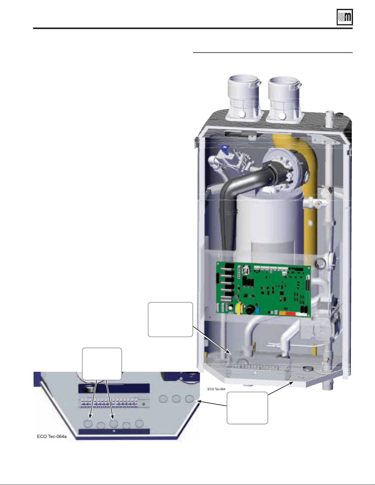
Field wiring overview - Line and low voltage
entrances
Part number 550-100-260/0520
59
ECO
®
Tec
GAS-FIRED WATER BOILER – 80/110/150/199 BOILER MANUAL
Field wiring (continued)
4. Low water cutoff harness should be routed from
location shown in Figure 51, page 41 to control module
connection shown in Section G, page 63. Provide strain
relief and a seal at cabinet entry if mounted external of
the cabinet
.
5. Bundle all wires together with provided wire ties.
Loop
wire tie with bundled wires through wire tie mount
and secure mount to control bracket in bottom right
mounting hole.
6. After wires and connectors are attached to the control
terminal blocks, make sure wires are properly sealed in
the cabinet electrical entrances.
Line
voltage
knockouts
High voltage
junction box
Low
voltage
knockouts

Part number 550-100-260/0520
60
ECO
®
Tec
GAS-FIRED WATER BOILER – 80/110/150/199 BOILER MANUAL
Field wiring (see wiring diagram, Figure 70, page 66) (continued)
A. 120VAC Power Supply – REQUIRED
1. Provide and install a properly-sized, fused disconnect or
service switch as required by applicable codes. (15-amp for
most cases.)
a. Use table at right to determine total load.
2. Connect properly sized 120VAC power wiring to
ECO
Tec boiler line voltage terminal block T1 as shown
at right.
3. If possible, provide a surge suppressor in the supply power
line. This will reduce the possibilities of control damage due
to line surges.
4. Must wire ground to this terminal to provide boiler
grounding. Failure to properly ground the boiler can lead
to abnormal operation and potential hazards.
Boiler & boiler pump
(combined load)
Output 1 . . . . . . .
(2.2 amps max)
Output 2 . . . . . . .
(2.2 amps max)
Output 3 . . . . . . .
(2.2 amps max)
Output 4 . . . . . . .
(2.2 amps max)
TOTAL . . . . . . .
2.5 amps
____ amps
____ amps
____ amps
____ amps
See
Figure 70, page 66
for details
– As needed for systems
Note
: Input/Output 1 & 4 are unassigned/ not available in Combi models.
1. Output 1: (Heat Only) T2: 4, 5, & 6
2. Output 2: T2: 7, 8, & 9
3. Output 3: T3: 10, 11, & 12
4. Output 4: (Heat Only) T3: 13, 14, & 15.
5. Maximum load: 2.2 amps (use relay if circulator load is higher). See WARNING below.
6. These four outputs (Output 1, Output 2, Output 3, and Output 4) can
provide 120VAC to the following listed below:
A zone
circulator.
A system circulator.
A DHW circulator (used to circulate through an indirect tank).
An auxil
iary Item that must be energized during an input call, such as
an air damper.
7. When using inputs/outputs for heat/Indirect DHW demands, each input (Input 1,
Input 2,
Input 3, and Input 4
) controls its respective 120VAC output (Output 1,
Output 2,
Output 3, and Output 4
). Outputs are energized only when BOTH
conditions below are met:
a. The corresponding input indicates a call for heat/ Indirect DHW (i.e. contact
closure).
b. The PRIORITY assigned to the Input/Output pair is ACTIVE (i.e. the zone may
be calling but the pump won’t activate unless the boiler is currently running on
that system/priority).
The 3-way valve will operate for Combi models, activating Output 1 for
Combi DHW calls, and activating Output 4 for any Space Heating calls.
8. When using the inputs/outputs for the AUX PUMP/OUTPUT function, the output
is controlled by selectable conditions set up in the control.
a. Use the AUX PUMP/OUTPUT function for devices such as system pumps,
combustion air dampers, and other auxiliary equipment to activate when the
selected condition is met.
b. See page 91 and page 93 for more information on the setup and selection of
operating conditions.
:
The DHW aquastat can be connected to any one of the four
(4) input/output pairs for Heat Only models and Inputs 2 or
3 for Combi models. The selected input should be assigned to
PRIORITY 1 during the WIZARD setup or manually in the System
Settings menu for Heat Only models or Priority 2 for Combi models.
See
Figure 70, page 66
for details.
—
.
For circulators with higher amp ratings, install a circulator
relay or starter. Connect only the 120VAC coil to the circulator
terminals.
Combi models use Input/Output pairs 1 and 4 for 3-way valve operation and cannot be used for any
other purpose. Use Input 2 for Indirect DHW (if needed) and Input 3 for Space Heating applications.
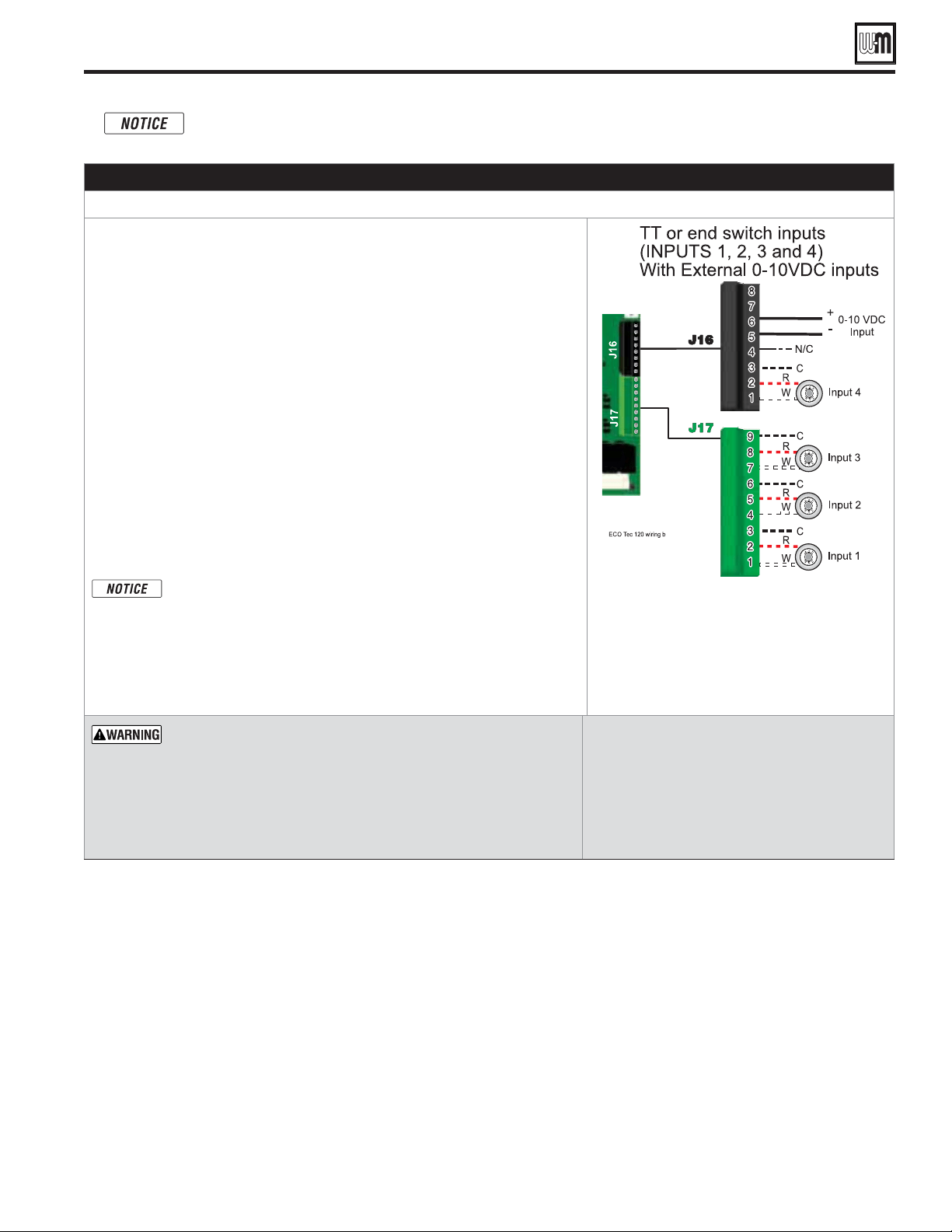
Part number 550-100-260/0520
61
ECO
®
Tec
GAS-FIRED WATER BOILER – 80/110/150/199 BOILER MANUAL
– As needed for systems
1. Input 1 – Connector J17 – 1, 2 & 3 (common)
2. Input 2 – Connector J17 – 4, 5 & 6 (common)
3. Input 3 – Connector J17 – 7, 8 & 9 (common)
4. Input 4 – Connector J16 – 1, 2 & 3 (common)
5. These four (4) inputs on each boiler can indicate a call for heat to the
control by means of a dry contact closure (thermostat, aqua
stat, or switch).
(See right and Figure 70, page 66).
6. The control provides inputs for up to four demands and up to three systems
(priorities).
7.
:
The DHW aquastat can be connected to any one of the four (4) input/output pairs
for Heating Only models and Inputs 2 or 3 for Combi models. The selected input
should be assigned to PRIORITY 1 during the WIZARD setup or manually in the
System Settings menu for Heating Only models or Priority 2 for Combi models
8. The default control setting uses each input (INPUT 1, INPUT 2, INPUT 3 and
INPUT 4) to control its respective 120VAC output (OUTPUT 1, OUTPUT 2,
OUTPUT 3 and OUTPUT 4). For Combi models, input 1 and 4 and output
1 and 4 are reserved for Combi calls for heat and 3-way valve operation.
Use of 0–10VDC input for modulation disables Input 2 T/T input
from creating calls for heat. See page 65 for instructions.
An input can be assigned to an AUX PUMP/OUTPUT function to
operate a system pump or interlock with a combustion air damper.
Inputs assigned for this function cannot be used for heat demand
operation. See page 91 and page 93 for more information on the
setup and selection of operating conditions.
See
Figure 70, page 66
for details.
— supply 24-volt power to the thermostat
circuits (Input 1, Input 2, Input 3 and Input 4 in Figure 70, page 66)
or attempt to supply 24 volts for any other application.
For thermostats that require a continuous 24-volt power source,
connect the common wire (“C”)
(see
Figure 70, page 66
)
.
Do NOT
exceed total amp draw per thermostat.
— If using 3-wire zone valves, use
relays to provide dry contacts to the Control
thermostat connections. The zone valve end
switches of 3-wire valves carry 24VAC from the
valve.
— 0.1 amps.
Field wiring (see wiring diagram, Figure 70, page 66) (continued)
Combi models use Input/Output pairs 1 and 4 for 3-way valve operation and cannot be used for any
other purpose. Use Input 2 for Indirect DHW (if needed) and Input 3 for Space Heating applications.
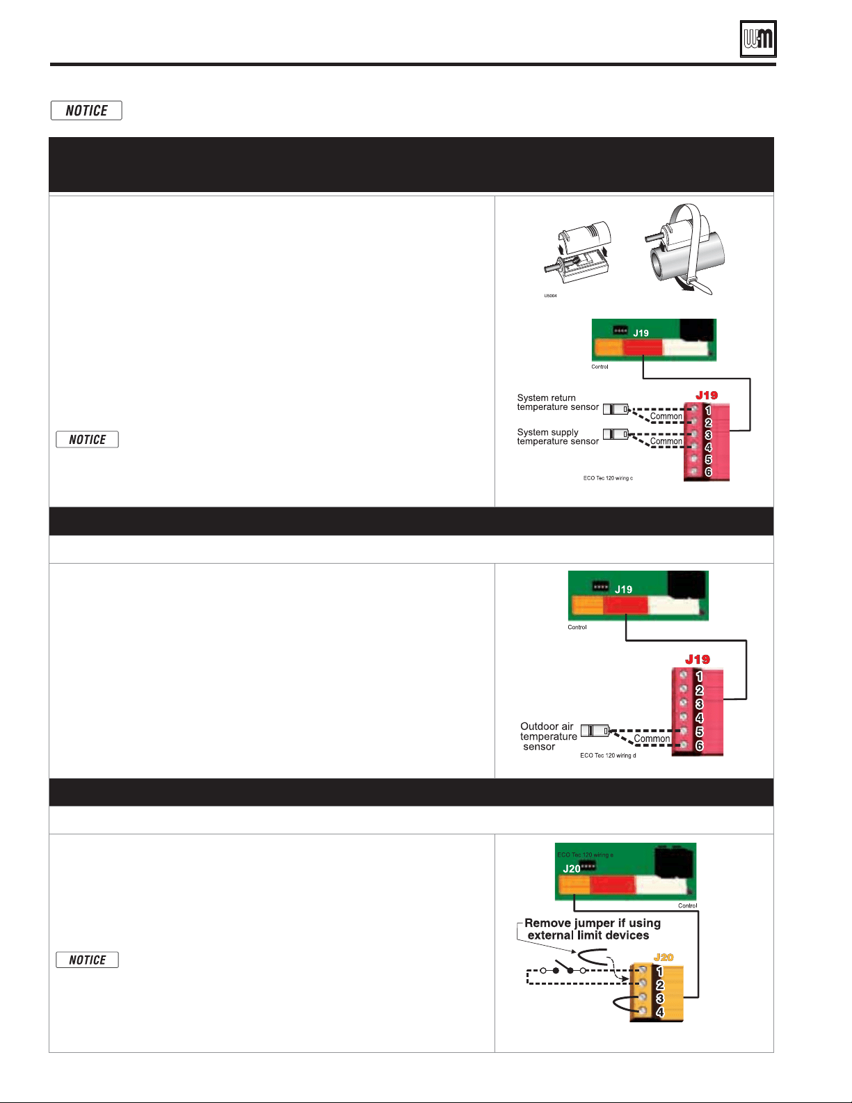
Part number 550-100-260/0520
62
ECO
®
Tec
GAS-FIRED WATER BOILER – 80/110/150/199 BOILER MANUAL
Field wiring (see wiring diagram, Figure 70, page 66) (continued)
Combi models use Input/Output pairs 1 and 4 for 3-way valve operation and cannot be used for any other
purpose. Use Input 2 for Indirect DHW (if needed) and Input 3 for Space Heating applications.
D. System supply and return temperature sensors – Recommended when using
primary secondary piping design. Connector J19
1. It is recommended to use two (2) strap-on temperature sensors (separate kit
option). Attach one to the system supply piping and the other to the system
return piping. For piping larger than 5 inch diameter or nonmetallic piping,
using immersion sensors will provide faster response.
2. Locate the supply sensor at least six pipe diameters, but no further than 3
feet, downstream from the boiler connection to the main to ensure adequate
mixing.
3. Return sensor – wire between J19 #1 and #2.
4. Supply sensor – wire between J19 #3 and #4.
5. Thermostat wire can be used to connect these sensors.
6. The Control compares the system return temperature with the system supply
temperature.
It is recommended for all primary/secondary heating systems
shown in this manual that the System Supply and Return sensors
to be installed for proper control function. System may not
properly provide desired temperature if sensors are not installed
according to these instructions.
Strap to supply & return piping
See
Figure 70, page 66
for details
E. Outdoor temperature sensor – REQUIRED unless exempted
Connector J19
1. The control provides programmable options if using an outdoor
temperature sensor. This sensor is supplied with the boiler.
2. The outdoor sensor must be installed unless specifically
exempted in the Energy Act statement on page 149.
3. Mount the outdoor sensor on an exterior wall, shielded from direct sunlight
or flow of heat or cooling from other sources.
4. The wire outlet on the sensor must be oriented DOWN to prevent water
entry.
5. Connect the sensor leads to the terminal shown at right and in the wiring
diagrams (see
Figure 70, page 66
). Thermostat wire can be used to connect
the sensor.
See
Figure 70, page 66
for details
F. External limits – OPTIONAL
To cause MANUAL reset: Connector J20 #1 & #2
The control will require manual reset after circuit is interrupted
.
1. Remove factory-installed jumper and connect isolated contacts of external
limits across J20 pins 1 and 2 to cause the control to enter manual reset
lockout if the limit circuit opens. The limit must close and the control must
be manually reset using the procedure given in this manual. See drawing
at right and wiring diagram
Figure 70, page 66
.
The control will lockout when a limit in its manual reset circuit
opens (J20 pins 1 & 2). The control activates its alarm terminals
and shuts the boiler down. An operator (user or technician) must
manually reset the control to restart the boiler.
See
Figure 70, page 66
for details.
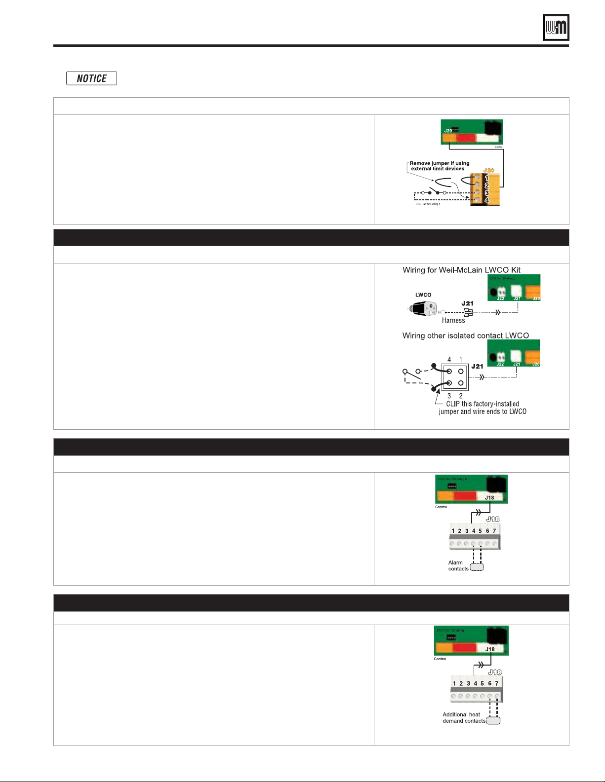
Part number 550-100-260/0520
63
ECO
®
Tec
GAS-FIRED WATER BOILER – 80/110/150/199 BOILER MANUAL
AUTOMATIC
1. Remove factory-installed jumper and connect isolated contacts of external
limits across J20 pins 3 and 4 to cause the control to shut down the boiler on
limit opening, then automatically restart 150 seconds after the limit closes.
2. See drawing at right and wiring diagram (
Figure 70, page 66
).
See
Figure 70, page 66
for details.
G. Low water cutoff (LWCO) – Required (Installer Supplied)
1. Install a low water cut-off (required) (see Figure 51, page 41).
2. Wiring Weil-McLain LWCO Kit:
a. When possible, use the Weil-McLain Low water cut-off kit listed in the back
of this manual. It includes a probe-type low water cut-off and provides a
simple harness connection for the wiring.
b. Connect as shown at bottom center in the control wiring diagram
(
Figure 70, page 66
)
.
3. Wiring another LWCO — must have isolated contact:
a. Other low water cut-offs can be used with the ECO
Tec only if the device
uses an isolated contact for the LWCO function.
b. Connect as shown at bottom right.
See
Figure 70, page 66
for details.
H. Alarm contacts – OPTIONAL
1. The control’s alarm dry contact (J18, terminals 4 and 5) closes when the
boiler enters manual lockout only.
2. Connect these terminals for remote alarm notification.
3. Contact electrical ratings: 24VAC or less; 0.5 amp or less.
See Figure 70, page 66 for details.
I. Additional heat demand contacts – OPTIONAL
1. The circuit board can be set to activate another heat source using its additional
heat demand dry contacts through terminal block J18 pins 6 & 7.
2. Connect these terminals to call for heat from the other heat source.
3. Contact electrical ratings: 24VAC or less; 0.5 amp or less.
4. Set the control to activate the heat demand contacts as needed.
5. For Additional Heat Demand , refer to setup in Control section for more
information.
See Figure 70, page 66 for details.
Field wiring (see wiring diagram, Figure 70, page 66) (continued)
Combi models use Input/Output pairs 1 and 4 for 3-way valve operation and cannot be used for any
other purpose. Use Input 2 for Indirect DHW (if needed) and Input 3 for Space Heating applications.
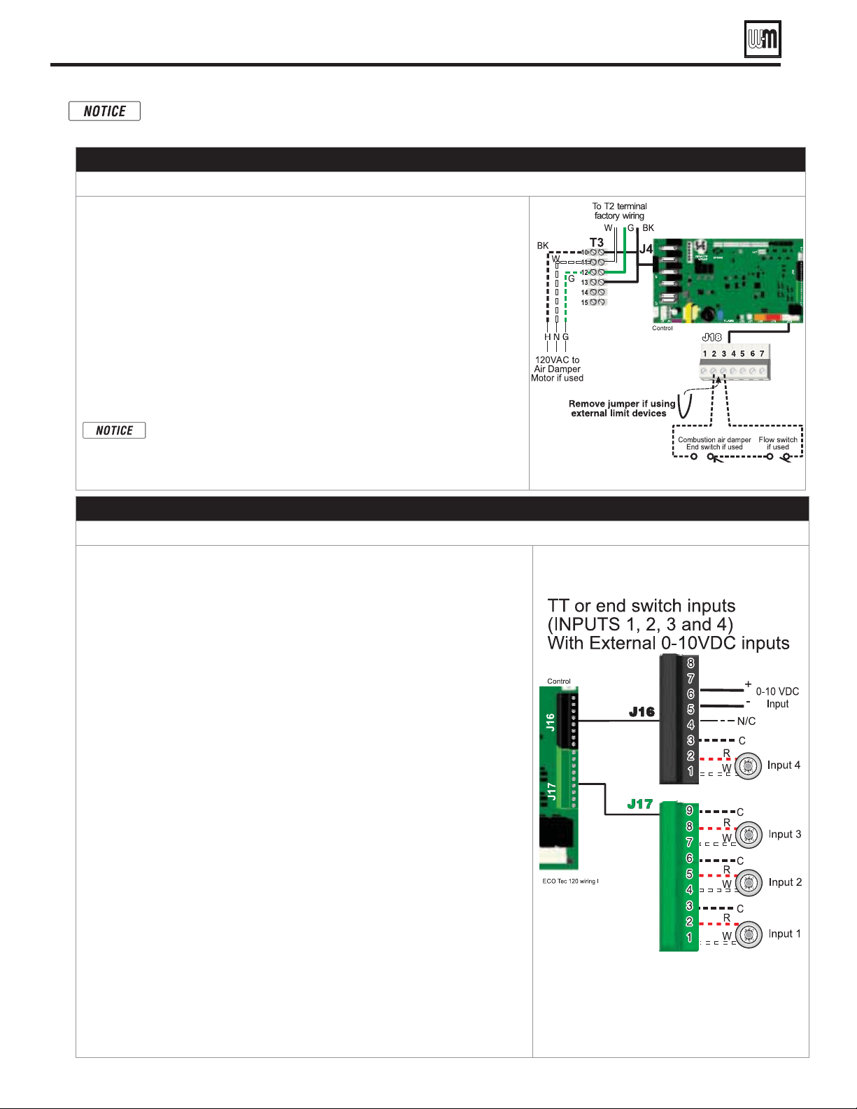
Part number 550-100-260/0520
64
ECO
®
Tec
GAS-FIRED WATER BOILER – 80/110/150/199 BOILER MANUAL
J. Proof of closure (flow switch and/or CAD)
1. A flow switch or combustion air damper (CAD) interlock can be configured
by removing the jumper on connector J18 and wiring components as shown
at right and in the wiring diagram
(
Figure 70, page 66
)
.
2. No control settings are required when using a flow switch.
3. Recommended configuration of the control for a CAD interlock:
a. Assign
as a function.
b. For the
operating mode, select local or
for use with CAD Interlock. This ensures the damper will be
activated any time the boiler is called on to fire.
c.
will provide 120VAC to the damper motor. Use an isolation
relay if damper motor requires another voltage or more than 2.2 amp if
using 120VAC.
*
The devices used must provide electrically isolated contacts,
because the J18 jumper circuit carries 5 VDC.
See
Figure 70, page 66
for details.
K. 0–10 VDC Remote TARGET input – OPTIONAL
1. See illustration at right and Figure 70, page 66 (wiring diagram) for details.
2. Remote target using 0–10VDC input requires a 0–10VDC input signal at J16-5/6 as
shown at right.
a. The input positive connection must be at J16 terminal 6 and the common connection
at terminal 5.
3. This illustration also shows how to connect TT or end switch contacts at INPUT 1,
INPUT 2, INPUT 3 and INPUT 4.
a. If a Heat/Indirect DHW demand is required, connect the demand’s dry contact to
an unused input on the control and its pump/valve to the respective output. Then
assign and setup a priority to the input using the Wizard or manually through the
contractor menu.
b. A dry contact heat demand must be applied to one of the inputs in order to initiate
a call for heat.
4. The 0–10VDC signal is used to adjust the supply target temperature, using the TARGET
ADJUST setting. Set TARGET ADJUST during the WIZARD or manually in the
PRIORITY SETTINGS menu for the desired system/ priority.
a. Many options are available for configuring the control. The following is a suggested
setup that uses factory default settings as much as possible.
b. Use PRIORITY 1 for the Indirect DHW heating system when used. This priority’s
default values are set for Indirect DHW, direct-piped to the boiler. Verify that settings
are suitable for the application, change if needed. Use Priority 2 for Combi models.
c. Use PRIORITY 2 for the heating systems. Use PRIORITY 3 for Combi models.
The factory default settings for PRIORITY 2 or 3 make either priority a
good choice for space heating applications. Set PRIORITY 2/3 values to the
following:
Set TARGET ADJUST value to 0–10V.
Set VOLTS FOR MAX TARGET at the voltage that will call for the highest
target temperature. Set MAX TARGET TEMP at this temperature.
Set VOLTS FOR MIN TARGET at the voltage that will call for the lowest target
temperature. Set MIN TARGET TEMP at this temperature.
For voltages between VOLTS FOR MAX and VOLTS FOR
MIN, the target temperature will range proportionately
between MAX TARGET TEMP and MIN TARGET TEMP.
NOTE: The 0–10VDC signal replaces the Outdoor Temp sensor as the target
temperature modifier (TARGET ADJUST setting). The control does not control target.
See
Figure 70, page 66
for details.
Field wiring (see wiring diagram, Figure 70, page 66) (continued)
Combi models use Input/Output pairs 1 and 4 for 3-way valve operation and cannot be used for any
other purpose. Use Input 2 for Indirect DHW (if needed) and Input 3 for Space Heating applications.

Part number 550-100-260/0520
65
ECO
®
Tec
GAS-FIRED WATER BOILER – 80/110/150/199 BOILER MANUAL
L. 0–10 VDC Remote MODULATION input – OPTIONAL
1. See illustration at right and Figure 70, page 66 for details.
2. This illustration also shows how to connect TT or end switch contacts at
INPUT 3 and INPUT 4 for other uses.
3. Note that using 0–10VDC input replaces INPUT 2 for generating a heat
demand. Do NOT wire any input to INPUT 2 as shown at right.
4. Remote modulation requires a 0–10VDC input signal at J16-5/6 as shown
at right.
a. The 0–10VDC input positive connection must be at terminal 6 and
common connection at terminal 5.
5. Control setup:
a. Many options are available for configuring the control. The following is
a suggested setup that uses factory default settings as much as possible.
b. If Indirect DHW is required, use PRIORITY 1 to minimize setup steps.
Connect the DHW aquastat to INPUT 3, or INPUT 4 and assign the
input used to PRIORITY 2.
Verify that control settings are suitable for the application, change
if necessary.
c. Use PRIORITY 3 for the system to be remote modulated.
The factory default settings for this priority are best suited for space
heating.
Assign INPUT 2 to the priority chosen. Accept all defaults for INPUT 2
— no changes should be necessary during the WIZARD.
After the WIZARD has been completed, go to the SYSTEM SETTINGS
– INPUT USAGE menu for INPUT 2. Change SOURCE to 0–10V
(default setting is TT1). See page 92 for System Settings menu
information.
6. Operation:
a. The boiler comes on at 0.9VDC and turns off at 0.8VDC. 1 VDC = 10%
input. 10 VDC = 100% input. These voltage settings are not adjustable.
b. OUTPUT 2 (120VAC) is activated and deactivated as the heat demand
is turned on and off. This output is a good choice to operate the system
pump.
NOTE: The control can be configured to use either 0–10VDC for target operation
(see previous section) or modulation,
.
See
Figure 70, page 66
for details.
Field wiring (see wiring diagram, Figure 70, page 66) (continued)
Combi models use Input/Output pairs 1 and 4 for 3-way valve operation and cannot be used for any
other purpose. Use Input 2 for Indirect DHW (if needed) and Input 3 for Space Heating applications.
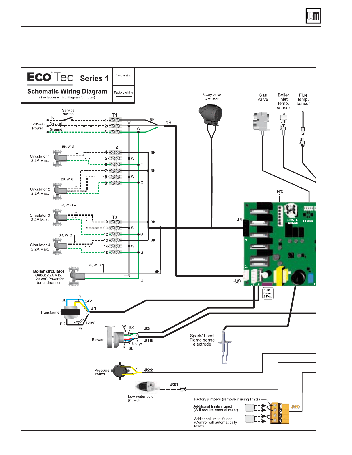
Part number 550-100-260/0520
66
ECO
®
Tec
GAS-FIRED WATER BOILER – 80/110/150/199 BOILER MANUAL
Wiring diagram — schematic
Schematic wiring diagram (see Figure 71, page 68 for legend and notes)
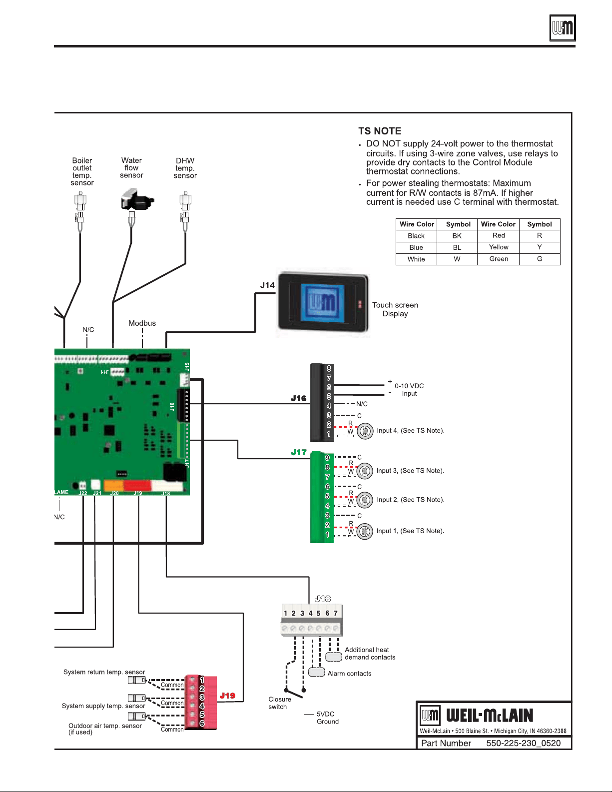
Part number 550-100-260/0520
67
ECO
®
Tec
GAS-FIRED WATER BOILER – 80/110/150/199 BOILER MANUAL
Wiring diagram — schematic (continued)

Part number 550-100-260/0520
68
ECO
®
Tec
GAS-FIRED WATER BOILER – 80/110/150/199 BOILER MANUAL
Wiring diagram — ladder
Ladder wiring diagram (see Figure 70, page 66 for schematic wiring diagram)
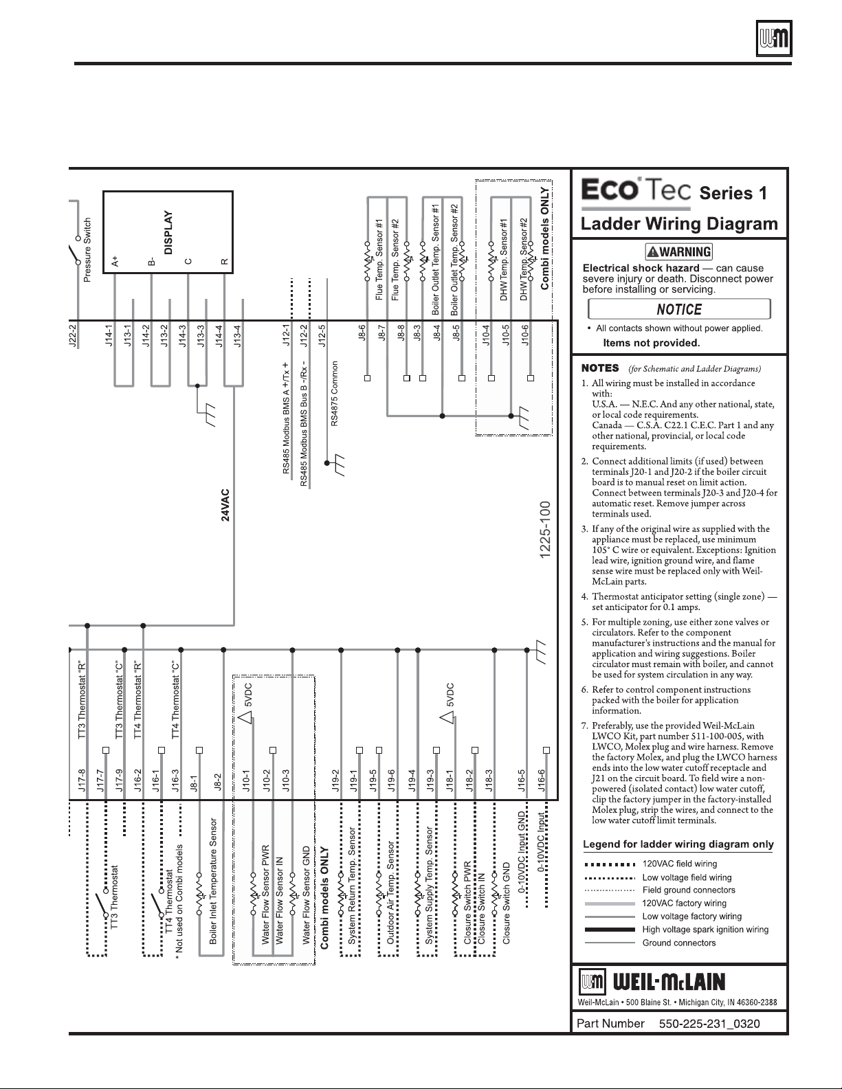
Part number 550-100-260/0520
69
ECO
®
Tec
GAS-FIRED WATER BOILER – 80/110/150/199 BOILER MANUAL
Wiring diagram — ladder (continued)
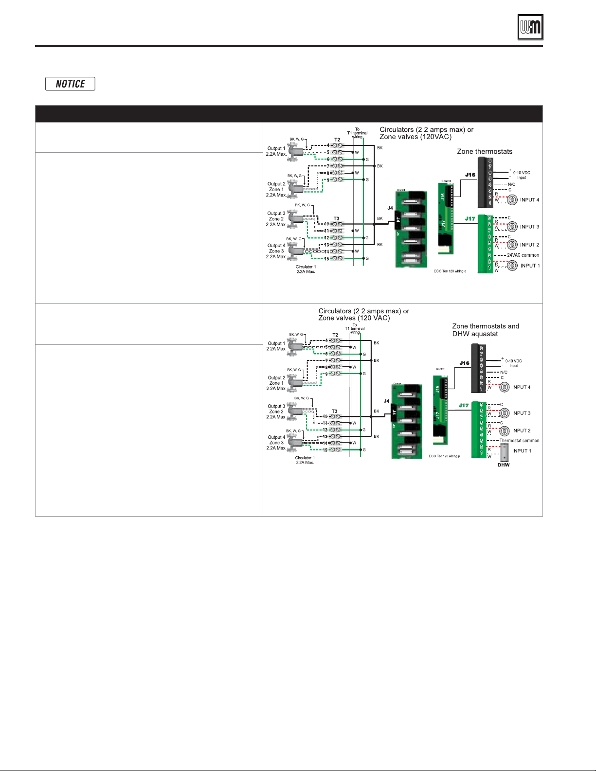
Part number 550-100-260/0520
70
ECO
®
Tec
GAS-FIRED WATER BOILER – 80/110/150/199 BOILER MANUAL
Zoning with the ECO Tec Control
A. Zoning with CIRCULATORS, suggested applications
1. Review wiring information on page 60 (120VAC
outputs) and page 61 (24VAC inputs).
2. The configuration at right uses the four input/output
pairs to receive thermostat inputs on J17-1/2, J17-4/5,
J17-7/8 and J16-1/2; and circulator outputs as shown.
3. Choose the space heating system type that matches the
heating system during the WIZARD setup or manually
in the PRIORITY 2 menu in the System Settings menu.
4. Use the factory default settings for the system type
chosen, or change if needed.
1. Review wiring information on page 60 (120VAC
outputs) and page 61 (24VAC inputs).
2. The configuration at right uses INPUT 3 and 4 for
space heating thermostats. INPUT 1 uses the input
from a DHW aquastat.
3. System Settings 2, 3 and 4 to PRIORITY 2. To set up
PRIORITY 2, choose the space heating system type
that matches the heating system during the WIZARD
setup or manually in the PRIORITY 2 menu in the
System Settings menu.
4. Assign INPUT 1 to PRIORITY 1, or use INPUT 2
PRIORITY 2 for Combi models.
5. Use the factory default settings for DHW and for the
heating system type chosen, or change if needed.
Combi models use Input/Output pairs 1 and 4 for 3-way valve operation and cannot be used for any
other purpose. Use Input 2 for Indirect DHW and Input 3 for Spacing Heating applications.
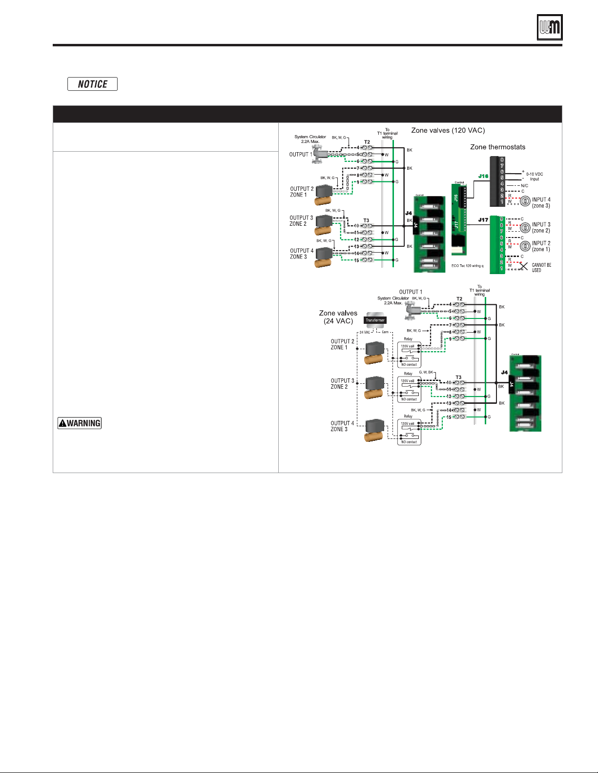
Part number 550-100-260/0520
71
ECO
®
Tec
GAS-FIRED WATER BOILER – 80/110/150/199 BOILER MANUAL
Zoning with the ECO Tec Control (continued)
B. Zoning with ZONE VALVES, suggested applications
1. Review wiring information on page 60 (120VAC
outputs) and page 61 (24VAC inputs).
2. The configuration at right uses INPUT 2, 3, and 4 for
space heating thermostats. INPUT 1 is reserved here
for configuring the operation of the system circulator.
3. System Settings 2, 3 and 4 to PRIORITY 2. To set up
PRIORITY 2, choose the space heating system type
that matches the heating system during the WIZARD
setup or manually in the PRIORITY 2 menu in the
System Settings menu.
4. Use the factory default settings for the heating system
type chosen, or change if needed.
5. Assign INPUT 1 (Input 2 for Combi models )to AUX
PUMP/OUTPUT. Then select INPUTS PRIORITY
SETTING when prompted for when to activate the
output. This will cause the system pump to run
when either of the zones calls for heat. Confirm that
Priority 2 RUN AUX PUMP/OUT is set to YES.
6. INPUT 1, J17-1/2, (Input 2, J17-4/5 for Combi
models) cannot be used for a wired connection
because it is being used in the control setup to run
the system circulator.
The system must be equipped with a by-pass
pressure regulating valve. Flow can occur
with zone valves closed.
Combi models use Input/Output pairs 1 and 4 for 3-way valve operation and cannot be used for any
other purpose. Use Input 2 for Indirect DHW and Input 3 for Spacing Heating applications.

Part number 550-100-260/0520
72
ECO
®
Tec
GAS-FIRED WATER BOILER – 80/110/150/199 BOILER MANUAL
ECO
Tec
1. Set control parameters using the WIZARD option provided on
initial start-up or manually enter parameters using control menus
(see Figure 80, page 87 and following pages for information.)
2. See
instructions beginning on page 78 for basic
systems and minimum settings required.
Failure to set correctly could result in severe personal injury, death or
substantial property damage.
— You must ensure that the control is set for the
proper water temperatures for the system. Excessive water temperature
can cause significant property damage in some applications.
— If the heating system includes circuits
that require lower temperature water (radiant slab circuits, for example)
as well as higher temperature circuits (DHW, finned tube baseboard,
etc.), it is recommended to protect low-temperature circuits with limit
controls that are wired to an control external limit circuit. Failure to
provide regulation can result in substantial property damage.
Control features
❏
Color touch-screen display for ease of operation monitoring and
troubleshooting.
❏
Three programmable priority assignments for up to four heat inputs.
❏
Preset operating parameters for typical heating systems, including
target temperatures, reset curves and circulator assignments.
❏
Integral outdoor reset option, with reset curves matched to the system
type selected.
❏
ModBus communications for external communication and
monitoring.
❏
0-10VDC input modulation or remote target input.
❏
Five (5) pump outputs, including 1 internal boiler circulator output.
❏
Additional heat demand operation to call a second heat source to help
supply the energy required for heating.
❏
Advanced PI response to anticipate system needs.
❏
Flue temperature modifier to target temperature.
❏
Modulation based on flue sensor, Boiler In/Boiler out, and DHW sensors.
Control sequence of operation
(also see Figure 76, page 76)
Check the boiler model listed on the power-up screen.
If it is not correct, turn off the boiler. See page 88 for
instructions to change setting.
When power is turned on, the screen lists sensors that
are detected. If any sensor is not listed, make sure it is
connected correctly. Turn off power and restart.
Standby - no calls for heat.
Toggles through no dots, 1 dot, 2 dots, then 3 dots
while in standby (wrench symbol will show instead if
maintenance is needed).
Call for heat detected.
Display on with BLUE banner (space heating) or
PURPLE banner (DHW).
Start min/max timers if more than one system is calling
- highest priority starts first.
Start circulators for this priority setup based upon
settings.
Calculate target temp — If sensor temp is below target
temp, begin firing sequence.
Blower to ignition speed for prepurge.
After prepurge times out, begin ignition cycle.
Activate gas valve and ignition spark.
Continue ignition spark for ignition period.
Turn off spark and use electrode to check for flame
signal.
Flame detected.
Release boiler to modulation.
NOTE: If flame is not detected, the gas valve is turned
off, blower turns on (postpurge), and control starts
cycle again. After 5 failures, the control waits 60
minutes, then tries again.
If priority timer times out, switch to next priority and
start priority timer.
If demand satisfied, go to postpurge.
Demand satisfied (temperature reaches target
temperature or limit setting).
Gas valve off.
Blower to ignition speed for postpurge.
Return to standby after purge.
Display banner turns BLUE, toggling between graphic
screen and maintenance screen (occurs if maintenance
schedule timer times out).
Will show during standby only.
Boiler operates as normal.
Display banner turns RED due to error or limit event.
Warm weather shut down - the boiler will not be
allowed to fire on space heating if the outdoor
temperature is greater than the WWSD setting.
DHW operation is not affected by WWSD.
ECO Tec control operation
ECO
Tec
Control inputs and outputs allow operation of multiple heating circuits
(space heating and DHW, for example).
Up to three priority levels can be set, providing automatic switch-over
on demand.
This manual provides quick set-up information for boiler installations.
ECO
Tec
The control responds to signals from the room thermostats, DHW
aquastats (if used), boiler sensors (Boiler out, Boiler In, flue temperature),
outdoor temperature and system sensors, if used.
The control automatically adjusts blower speed (and gas flow rate) to
match boiler output to space heating and/or DHW heating demand.
The default control settings provides up to four (4) space heating zones.
The control can be easily set up for operation with a DHW zone, with or
without domestic priority.
ECO
Tec
WIZARD
The Wizard leads through a step-by-step setup procedure designed for
the application chosen.
Context-sensitive help is available to explain the purpose of key setup
Items.
Part number 550-100-260/0520
73
ECO
®
Tec
GAS-FIRED WATER BOILER – 80/110/150/199 BOILER MANUAL
Setting Up the Boiler
Step 1
Step 2
Step 3
Step 4
ECO
Tec control WIZARD
The Wizard is available on initial setup of the boiler. It
leads through a step-by-step setup procedure designed
for the application chosen.
Context-sensitive help is available to explain the purpose
of key setup Items.
WIZARD Sequence
Boiler
Settings
Inputs/
Outputs
Set
Priorities
System
Settings
System
Types
Output
Activation
Priority
Switching
Information
ECO Tec control operation (continued)
❏
Dual temperature sensors on boiler outlet, DHW outlet and flue,
providing redundant protection.
❏
Boiler is shipped with an outdoor sensor.
❏
Blower speed modulation to control boiler firing rate.
❏
Alarm relay on error/fault for use with an audible safety.
❏
Optional PREHEAT mode – Automatically maintains boiler water
temperature to reduce boiler reaction time on Combi domestic hot
water (DHW) draws.
❏
Select the mode of PREHEAT, between Off, Economy and High
Performance.
❏
ECO BOOST – Reacts to homeowner use to recharge boiler water
temperature once, if needed to reduce boiler reaction time on subsequent
Combi domestic hot water (DHW) draws.
❏
Select whether or not to use the ECO BOOST feature. If conditions are
met, the burner will continue to fire after Combi flow ends to recover
temperature within the heat exchanger.
❏
Blower calibration – allows fine tuning of blower control to reach purge
speeds faster, reducing time to heat delivery
.
Sequence of operation
Figure 72, page 72 is a summary of the operating sequence for the
control.
The statuses shown appear in the display as the control cycles
the boiler. See Figure 76, page 76 for screen shots.
The display banner will be red if a problem has been detected.
ECO
Tec control Priorities & Input/Outputs
For heating installations with multiple systems, the control uses
PRIORITIES to determine the order of operation of the systems.
The control’s MAX and MIN time settings determine the maximum
and minimum times a system will be operated before being turned
off to allow another system to operate. A typical example is DHW
priority — heat demand from the DHW system is given preference
over space heating, if set to use Priority 1.
The MAX ON TIME setting controls the maximum time a priority
will be allowed to run before switching to a lower priority’s call for
heat. The MIN ON TIME setting controls the minimum time a
priority will be operated before switching to a higher priority’s call
for heat, or the next lower priority.
Each PRIORITY has its own set of operating parameters. The control
prompts the user to select the system type (finned tube baseboard,
DHW, etc.) and is factory programmed with parameters suited to
each of these system types. The user can also choose CUSTOM to
create a system type.
The 120VAC power output to the boiler circulator is provided by
a terminal block located on the boiler’s control board. For each of
the priorities, the control can be setup to run the boiler pump or
to leave it off.
Each boiler has four input/output pairs (INPUT/OUTPUT 1,
2, 3 and 4). Control setup prompts the user to assign each of these
I/O pairs to a PRIORITY. The control then knows which system
(priority) to operate when the input receives a call for heat. On a
call for heat to an input, the control closes the corresponding output
(120VAC) and begins controlling the boilers according to the setup
for the assigned priority.
When multiple inputs are set up on the same priority, they will run
at the same time if the priority and inputs are active.
Temperature units – Select between using
°
F or
°
C.
Manual Reset High Temperature Limits – Set High Limit
temperature safety value.
Daylight Saving Time – Select whether your boiler will obey Daylight
Savings Time for your region.
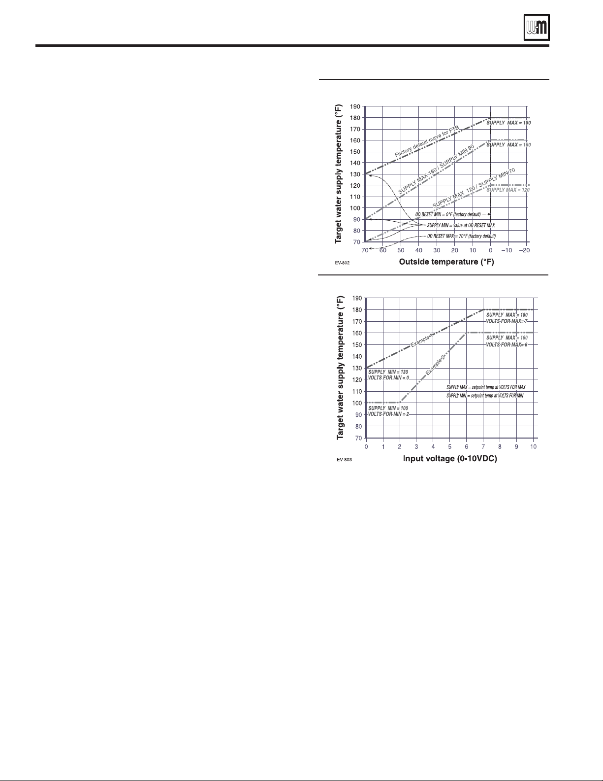
Part number 550-100-260/0520
74
ECO
®
Tec
GAS-FIRED WATER BOILER – 80/110/150/199 BOILER MANUAL
ECO Tec control operation (continued)
Outdoor reset operation
ECO
Tec control operation
The control responds to signals from:
DHW Flow demand.
Room thermostats.
DHW aquastats (if used).
Temperature sensors Boiler Out, Boiler In, flue temperature and
when used, outdoor temperature.
The control automatically adjusts blower speed (and gas flow rate) to
match boiler output to space heating and/or DHW heating demand.
The control provides four inputs and four outputs (for circulators
or auxiliary devices) plus a fifth boiler circulator output.
Outdoor reset must be used in all applications that are not exempt
as described on page 149.
The outdoor temperature is used for supply temperature reset
operation and for the Warm Weather Shut Down (WWSD) option.
System presets:
The ECO
Tec control provides presets by system type for
complete list, see Figure 79, page 85.
DHW Target
Set DHW target to the required Combi DHW water temperature for the
application according to design mixing valve.
1. OUTDOOR TEMP FOR MIN TARGET means the outdoor
temperature at which the target temperature reaches its minimum
(Min Target Temp).
2. In the examples of Figure 73, this occurs at 70 °F (the factory default).
1. OUTDOOR TEMP FOR MAX TARGET means the outdoor
temperature at which the target temperature reaches its maximum
value (Max Target Temp).
2. In the examples of Figure 73, this occurs at 0°F outdoor (the factory
default setting).
3. OutDOOR TEMP FOR MAX TARGET should equal the Outdoor
Temp (outdoor design temperature) for the installation’s location.
Outdoor reset operation
4. Set desired temperatures for space heating zones.
5. For an explanation of the target temperatures and associated outdoor
temperatures, see Figure 73.
6. The temperature settings discussed below are accessed in the priority
menu for the applicable system. For detailed explanations of the
priority menus, see Figure 82, page 89.
Set Max Target Temp to the required supply water temperature for the
system at design maximum heat loss (typically 180°F for finned tube
baseboard on new installations).
1. Min Target Temp should equal the desired minimum supply water
temperature for the system.
2. This could be set as low as 60°F, which would supply “zero heat”
when outdoor temperature is 70°F, because supply water temperature
would equal room temperature. See examples in Figure 73.
Remote target operation (0–10VDC input)
1. This function allows a remote analog input to regulate the supply
temperature for control operation/modulation. This can be done
for any priority.
2. The settings discussed below are accessed in the priority
menu for the applicable system. For detailed explanations
of the priority menus, see Figure 82, page 89.
3. See Figure 74 for an explanation of target temperature vs
voltage when using remote target operation.
4. In the priority menu for the applicable system, select
0-10V for the TARGET ADJUST setting.
5. In the same priority menu, select the VOLTS FOR MIN
TARGET and VOLTS FOR MAX TARGET values. VOLTS
FOR MIN TARGET sets the voltage value for the desired
minimum supply temperature. VOLTS FOR MAX
TARGET sets the voltage value for the desired maximum
supply temperature.
Remote modulation operation
(0–10VDC input)
1. To use 0-10VDC for remote modulation, go to Contractor
Menu -> System Settings -> select the appropriate
priority. Select Input 1 from System Setting menu, then
change Input 1’s source to 0-10V. The priority that is
assigned to Input 1 cannot be used by any other Input.
2. The boiler comes on at 0.9VDC and turns off at 0.6VDC.
1 VDC = 10% input. 10VDC = 100% input. These voltage
settings are adjustable.
Remote target operation
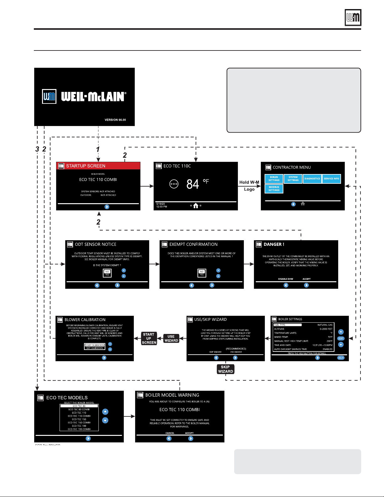
Part number 550-100-260/0520
75
ECO
®
Tec
GAS-FIRED WATER BOILER – 80/110/150/199 BOILER MANUAL
ECO Tec control operation (continued)
Boiler essential settings (REQUIRED on initial start-up) — see page 84 for explanation
Screen branching options
1. Occurs when a control is powered up after being
2. Occurs when a factory-installed control is powered
3.
when a control is reset to factory defaults; will not
be shown on new boilers (because control has
been factory tested).
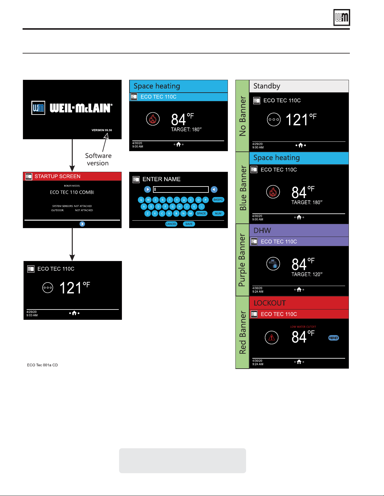
Part number 550-100-260/0520
76
ECO
®
Tec
GAS-FIRED WATER BOILER – 80/110/150/199 BOILER MANUAL
Control settings menus
ECO
Tec control display screens and typical navigation
Keyboard: Appears when editing
name of inputs/outputs and
contractor information.
Navigation controls
Swipe: 6OLGHÀQJHUOHIWRUULJKWRQWKHVFUHHQWRQDYLJDWHIRUZDUGDQGEDFNZDUGRQDSSOLFDEOHVFUHHQV
Press: 7RXFKLFRQVRQVFUHHQWRSHUIRUPVSHFLÀHGDFWLRQ
Scroll: 3ODFHÀQJHURQVOLGHEDUHPSW\VSDFHDQGKROGWRVFUROO$SSOLFDEOHVFUHHQVFDQDOVREHVZLSHGXSRUGRZQWRVFUROO
Double tap:$SSOLFDEOHRQHGLWDEOHSDUDPHWHUV$OORZVXVHUWRHQWHUHGLWPRGHE\GRXEOHWDSSLQJSDUDPHWHU

Part number 550-100-260/0520
77
ECO
®
Tec
GAS-FIRED WATER BOILER – 80/110/150/199 BOILER MANUAL
Page Intentionally Blank
Part number 550-100-260/0520
78
ECO
®
Tec
GAS-FIRED WATER BOILER – 80/110/150/199 BOILER MANUAL
EXPRESS SETUP — Example A
SPACE HEATINGDHW
(Direct-piped)
CONTROL SETTINGS
(IN ORDER OF WIZARD SEQUENCES)
BLACK
OBLIQUE
- VALUE MUST BE SET OR VERIFIED
D — DEFAULT ACCEPTABLE; CHANGE ONLY IF DESIRED
BOILER SETTINGS
Verify model number is correct
Default (70 °F) or as required
Set to YES if above 5,500 feet
INPUT/OUTPUT 1
HEAT/DHW DEMAND
Select PRIORITY 1
DHW(D)
BOILER OUT(D)
NONE(D)
()
Yes(D)
INPUT/OUTPUT 2
HEAT/DHW DEMAND
PRIORITY 2
Select correct system type
Boiler In(D)
ODT(D)
YES(D)
INPUT/OUTPUT 3
NONE
PRIORITY SWITCH TIMES:
INPUT/OUTPUT 4
NONE
PRIORITY SWITCH TIMES:
Finish the WIZARD
Purpose
Space heating with multiple zones.
Zoning with circulators using circulator relays.
DHW piped directly to the boiler.
DHW priority — space heating is disabled during call
for heat from water heater.
Control setting notes
See the table at right for required and optional settings.
The sequence in the table follows the WIZARD.
If not using the WIZARD, follow instructions
elsewhere in this manual to enter the settings manually.
Circulators and piping
Provide an external relay and external power
to any circulator if its load rating exceeds 2.2
amps FLA, 3.6 amps locked rotor, or 16.4
amps in rush.
Piping must be primary/secondary as shown.
DHW circulator must be selected to handle the
pressure drop through the water heater and piping.
DHW circulator supplied by installer.
For some large indirect water heaters, the required flow
rate may require piping the water heater differently.
The control settings in table at right provide DHW
priority — space heating will be discontinued during
a call for DHW.
Zone circulators and relays supplied by installer. For
alternate zone wiring using a zone controller, see
page 70.
Boiler circulator is installed internally within the
boiler.
Follow all instructions in this manual for piping boiler
and system.
, set the USE of INPUT/
OUTPUT 1 to NONE. Keep all other wiring
as shown at right and follow all settings given
above for PRIORITY 2.
For Combi models, INPUT/OUTPUT 1 and 4
are NOT used and Priority 1 is assigned to
Combi DHW. Use INPUT/OUTPUT 2 and 3
and Priority 2 and 3 for this application.
Failure to set correctly could result in
severe personal injury, death or substantial property
damage.
Incorrect setup or piping can result in severe personal
injury, death or substantial property damage.
Use primary/secondary piping or equivalent unless
system meets requirements on page 46.
Verify that the correct system type is selected on the
control and that operating temperature settings are
suitable for the system. System and structural damage
can occur if temperatures are too high.

Part number 550-100-260/0520
79
ECO
®
Tec
GAS-FIRED WATER BOILER – 80/110/150/199 BOILER MANUAL
EXPRESS SETUP — Example A (continued)
SPACE HEATINGDHW
(Direct-piped)
LEGEND
ECO
Tec boiler.
Indirect water heater, if
used (domestic water
piping not shown) —
MUST be direct piped
to boiler to use default
control settings.
Relief valve, supplied
with boiler, field piped
— MUST be piped to
Boiler In connection
— see Figure 8, page 13
for information.
Relief valve piping
to drain.
DHW circulator.
Isolation valves.
Expansion tank.
Air separator.
Flow/check or spring
check valves.
Purge/drain valves.
Unions as needed
for service.
Return temperature
sensor.
Supply temperature
sensor.
Make-up water supply.
DHW Temperature and
Pressure relief valve
Zone circulators.
Boiler drain
valve, supplied with
boiler, field piped.
Pressure/temperature
gauge, supplied with
boiler, field piped.
Outdoor sensor.
120VAC power to
boiler — see page 60.
Control module.
= Items supplied with
boiler — all other Items
supplied by installer.
Part number 550-100-260/0520
80
ECO
®
Tec
GAS-FIRED WATER BOILER – 80/110/150/199 BOILER MANUAL
EXPRESS SETUP — Example B
SPACE HEATINGDHW
(Direct-piped)
, provide a fourth space heating zone
by setting up INPUT/OUTPUT 1 exactly the same as INPUT/
OUTPUT 2. Assign INPUT/OUTPUT 1 to PRIORITY
2. Wire the fourth zone thermostat to J17 – 1&2 and its
circulator to T2 – 4, 5, 6.
CONTROL SETTINGS
(IN ORDER OF WIZARD SEQUENCES)
BLACK
OBLIQUE
- VA LU E MUST BE SET OR VERIFIED
D — DEFAULT ACCEPTABLE; CHANGE ONLY IF DESIRED
BOILER SETTINGS
Verify model number is correct
Default (70 °F) or as required
Set to YES if above 5,500 feet
INPUT/OUTPUT 1
HEAT/DHW DEMAND
Select PRIORITY 1
DHW(D)
BOILER OUT(D)
NONE(D)
Yes(D)
INPUT/OUTPUT 2
HEAT/DHW DEMAND
PRIORITY 2
Select correct system type
Boiler In(D)
ODT(D)
(Outdoor Temp sensor must be installed)
YES(D)
INPUT/OUTPUT 3
If PRIORITY 2 is assigned, no further steps are required. If PRIORITY 3
is assigned, repeat the steps from INPUT/OUTPUT 2, above.
PRIORITY SWITCH TIMES:
INPUT/OUTPUT 4
If PRIORITY 2 is assigned, no further steps are required. If PRIORITY 3
is assigned, repeat the steps from INPUT/OUTPUT 2, above.
Finish the WIZARD
Failure to set correctly could
result in severe personal injury, death or substantial
property damage.
Incorrect setup or piping can result in severe
personal injury, death or substantial property
damage.
Use primary/secondary piping or equivalent unless
system meets requirements on page 46.
Verify that the correct system type is selected on
the control and that operating temperature settings
are suitable for the system. System and structural
damage can occur if temperatures are too high.
Purpose
Space heating with multiple zones.
Zoning with circulators using control outputs to
operate zone circulators (3 zones if space heating
only; or 2 space heating zones plus DHW.
DHW piped directly to the boiler.
DHW priority — space heating is disabled during
call for heat from water heater.
Control setting notes
See the table at right for required and optional
settings.
The sequence in the table follows the WIZARD.
If not using the WIZARD, follow instructions
elsewhere in this manual to enter the settings
manually.
Circulators and piping
Provide an external relay and external
power to any circulator if its load rating
exceeds 2.2 amps FLA, 3.6 amps locked
rotor, or 16.4 amps in rush.
Piping must be primary/secondary as shown.
DHW circulator must be selected to handle the
pressure drop through the water heater and piping.
DHW circulator supplied by installer.
For some large indirect water heaters, the required
flow rate may require piping the water heater
differently.
The control settings in table at right provide DHW
priority — space heating will be discontinued
during a call for DHW.
Zone circulators supplied by installer. For alternate
zone wiring using a zone controller, see page 71.
Boiler circulator is installed internally within the
boiler.
Follow all instructions in this manual for piping
boiler and system.

SPACE HEATINGDHW
(Direct-piped)
Part number 550-100-260/0520
81
ECO
®
Tec
GAS-FIRED WATER BOILER – 80/110/150/199 BOILER MANUAL
EXPRESS SETUP — EXAMPLE B (continued)
LEGEND
1 ECO
Tec boiler.
2 Indirect water heater, if
used (domestic water
piping not shown) —
MUST be direct piped
to boiler to use default
control settings.
3
Relief valve, supplied
with boiler, field piped
— MUST be piped to
Boiler In connection
— see Figure 8, page 13
for information.
4 Relief valve piping
to drain.
5 DHW circulator.
6 Isolation valves.
8 Expansion tank.
9 Air separator.
10 Flow/check or spring
check valves.
11 Purge/drain valves.
14 Unions as needed
for service.
15 Return temperature
sensor.
16 Supply temperature
sensor.
20 Make-up water supply.
23 DHW Temperature and
Pressure relief valve
24 Zone circulators.
25
Boiler drain
valve, supplied with
boiler, field piped.
30
Pressure/temperature
gauge, supplied with
boiler, field piped.
31 Outdoor sensor.
33 120VAC power to
boiler — see page 60.
35 Control board
= Items supplied with
boiler — all other Items
supplied by installer.

Part number 550-100-260/0520
82
ECO
®
Tec
GAS-FIRED WATER BOILER – 80/110/150/199 BOILER MANUAL
EXPRESS SETUP — Example C
SPACE HEATINGDHW
(Direct-piped)
CONTROL SETTINGS
(IN ORDER OF WIZARD SEQUENCES)
BLACK
OBLIQUE
- VA L U E MUST BE SET OR VERIFIED
D — DEFAULT ACCEPTABLE; CHANGE ONLY IF DESIRED
BOILER SETTINGS
Verify model number is correct
Default (70 °F) or as required
Set to YES if above 5,500 feet
INPUT/OUTPUT 1
HEAT/DHW DEMAND
Select PRIORITY 1
DHW (D)
BOILER OUT(D)
NONE(D)
Yes(D)
INPUT/OUTPUT 2
HEAT/DHW DEMAND
PRIORITY 2
Select correct system type
Boiler In(D)
ODT(D)
(Outdoor Temp sensor must be installed)
YES(D)
INPUT/OUTPUT 3
NONE
PRIORITY SWITCH TIMES:
INPUT/OUTPUT 4
NONE
PRIORITY SWITCH TIMES:
Finish the WIZARD
, set the USE of INPUT/
OUTPUT 1 to NONE. Keep all other wiring as
shown at right and follow all settings given above
for PRIORITY 2.
For Combi models, INPUT/OUTPUT 1 and 4
are NOT used and Priority 1 is assigned to
Combi DHW. Use INPUT/OUTPUT 2 and 3
and Priority 2 and 3 for this application.
Failure to set correctly could result in severe
personal injury, death or substantial property damage.
Incorrect setup or piping can result in severe personal
injury, death or substantial property damage.
Use primary/secondary piping or equivalent unless system
meets requirements on page 46.
Verify that the correct system type is selected on the
control and that operating temperature settings are
suitable for the system. System and structural damage can
occur if temperatures are too high.
Purpose
Space heating with multiple zones.
Zoning with zone valves. use 3-wire zone
valves — the voltage on the valve end switch will damage
the control. Use only 4-wire zone valves with isolated
end switches.
DHW piped directly to the boiler.
DHW priority — space heating is disabled during call
for heat from water heater.
Control setting notes
See the table at right for required and optional settings.
The sequence in the table follows the WIZARD.
If not using the WIZARD, follow instructions elsewhere
in this manual to enter the settings manually.
The system circulator is wired to OUTPUT 2. It will be
activated on any call for heat from a zone valve end switch.
Circulators and piping
Provide an external relay and external power to
any circulator if its load rating exceeds 2.2 amps
FLA, 3.6 amps locked rotor, or 16.4 amps in rush.
Piping must be primary/secondary as shown.
DHW circulator must be selected to handle the pressure
drop through the water heater and piping. DHW
circulator supplied by installer.
For some large indirect water heaters, the required flow
rate may require piping the water heater differently.
The control settings in table at right provide DHW
priority — space heating will be discontinued during a
call for DHW.
Zone valves and system circulator supplied by installer.
For alternate zone wiring using a zone controller, see
page 71.
A by-pass pressure regulator is recommended when used
in a zone valve system as shown in this express setup.
Boiler circulator is installed internally within the boiler.
Follow all instructions in this manual for piping boiler
and system.
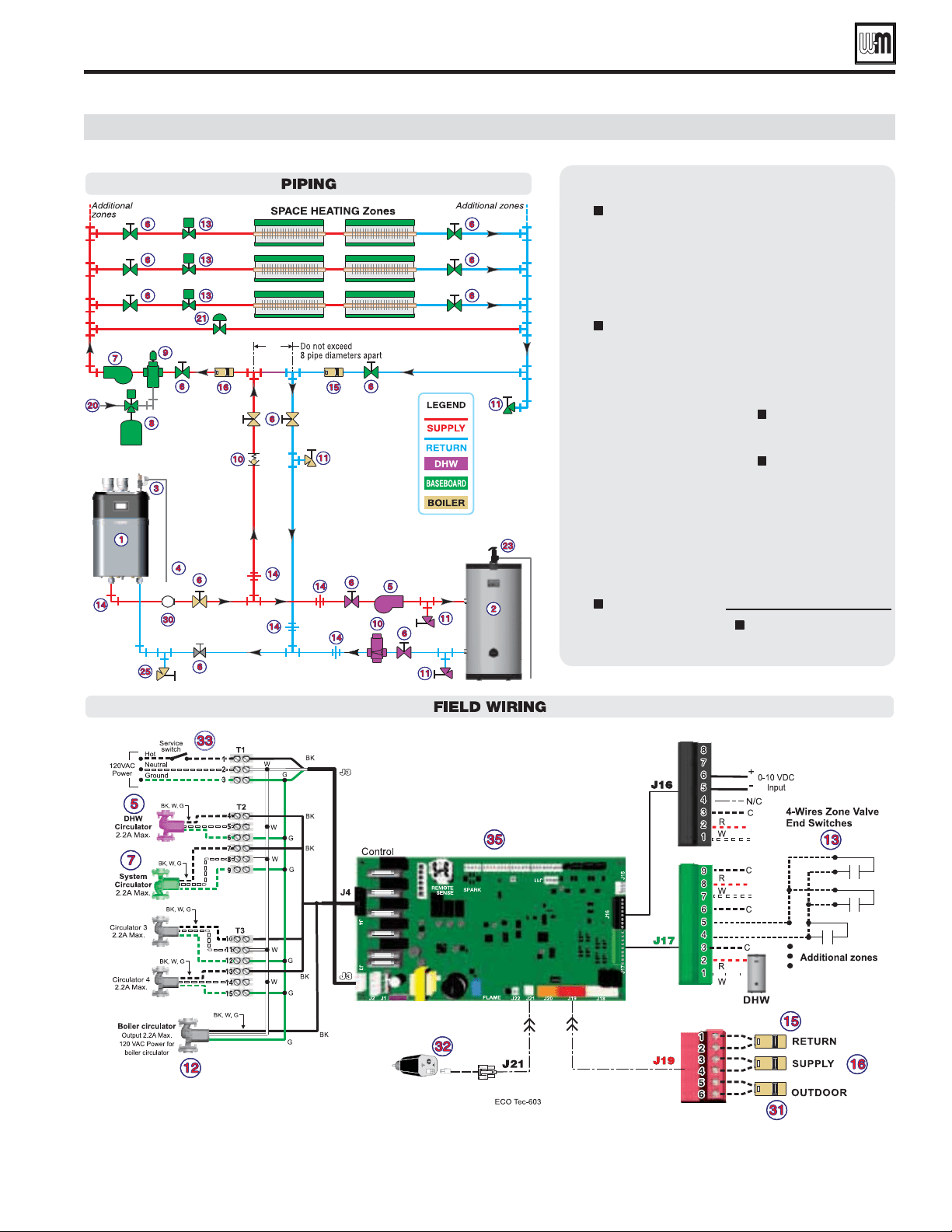
SPACE HEATINGDHW
(Direct-piped)
Part number 550-100-260/0520
83
ECO
®
Tec
GAS-FIRED WATER BOILER – 80/110/150/199 BOILER MANUAL
EXPRESS SETUP — EXAMPLE C (continued)
LEGEND
ECO
Tec boiler.
Indirect water heater, if
used (domestic water
piping not shown) —
MUST be direct piped
to boiler to use default
control settings.
Relief valve, supplied
with boiler, field piped
— MUST be piped to
Boiler In connection
— see Figure 8, page 13
for information.
Relief valve piping
to drain.
DHW circulator.
Isolation valves.
System circulator.
Expansion tank.
Air separator.
Flow/check or spring
check valves.
Purge/drain valves.
Boiler circulator,
supplied with boiler,
field piped.
Zone valves.
Unions as needed
for service.
Return temperature
sensor.
Supply temperature
sensor.
Make-up water supply.
By-pass pressure
regulator, REQUIRED
for zone valve systems.
DHW Temperature and
Pressure relief valve
Boiler drain
valve, supplied with
boiler, field piped.
Pressure/temperature
gauge, supplied with
boiler, field piped.
Outdoor sensor.
Low water cut-off.
120VAC power to
boiler — see page 60.
Control module.
= Items supplied with
boiler — all other Items
supplied by installer.
Part number 550-100-260/0520
84
ECO
®
Tec
GAS-FIRED WATER BOILER – 80/110/150/199 BOILER MANUAL
ECO
Tec Control / Priority settings
Available control settings and system presets
options
Default
setting
COMBI
default
UNITS
ASSIGNED INPUTS
1, 2, 3, 4, 0-10V, FLOW - FLOW -
See System Type Presets OFF 1=COMBI DHW -
SYSTEM SUPPLY,
BOILER OUT, DHW
OUT
SYSTEM SUPPLY if
detected, Boiler Out
if not
DHW OUT -
Outdoor Temp, 0-10V,
none
Outdoor Temp (If
attached)
None -
See System Type Presets
See System Type
Presets
N/A
°F
See System Type Presets N/A 120 °F
See System Type Presets
See System Type
Presets
N/A
°F
ON, OFF N/A ON -
50 - 100 70 N/A °F
-20 to 49 0 N/A °F
5.0 - 10.0 10.0 N/A V
0.0 - 4.9 0.0 N/A V
OFF, 1 - 240 OFF N/A M
5 - 15 10 N/A °F
DHW OFF DIFF
1 - 20 N/A 10 °F
5 - 30 10 N/A °F
DHW ON DIFF
1 - 20 N/A 1 °F
See System Type Presets
See System Type
Presets
See System Type Presets °F
2 - 15 5 5 °F
2 - 30 5 5 °F
0 - 150 50 50 °F
MAX ON TIME
OFF, 1 - 240 30 30 M
MIN ON TIME
OFF, 1 - 240 15 N/A M
OFF, Economy,
High Performance
Economy OFF -
70 - 180 N/A 120 (Econ), 140 (H. Perf) °F
1 - 30 N/A 30 (Econ), 10 (H. Perf) °F
1 - 30 N/A 10 (Econ), 5 (H. Perf) °F
1 - 30 N/A 10 °F
ECO BOOST
OFF, ON N/A ON -
ECO BOOST SETPOINT
70 - 180 N/A 130 °F
ECO BOOST ON DIFF
1 - 30 N/A 10 °F
Part number 550-100-260/0520
85
ECO
®
Tec
GAS-FIRED WATER BOILER – 80/110/150/199 BOILER MANUAL
8-Character
Abbreviation
3-Character
Abbreviation
Max
Target
Temp
°F
DHW
Target
°F
OD
Reset
Min °F
Min
Target
Temp
°F
OD
Reset
Max °F
Run
Boiler
Pump
Run AUX
PUMP/
OUTPUT
Fan-coil FAN-COIL
FCL 180 N/A 0 140 70 YES YES
Finned Tube Baseboard FIN BASE
FTB 180 N/A 0 130 70 YES YES
Cast Iron Baseboard IRONBASE
CIB 180 N/A 0 120 70 YES YES
Cast Iron Radiators RADIATOR
CIR 180 N/A 0 120 70 YES YES
Radiant - slab on grade RAD SLAB
RSG 120 N/A 0 80 70 YES YES
Radiant - thin slab RAD SLAB
RTS 140 N/A 0 80 70 YES YES
Radiant - below floor
(staple up)
RADFLOOR
RSU 160 N/A 0 90 70 YES YES
Radiant - above floor
(sleeper system)
RADFLOOR
RAF 140 N/A 0 90 70 YES YES
Domestic Hot Water DOMESTIC
DHW 180 N/A N/A N/A N/A YES NO
Combi DHW COMBI
DHW N/A 120 N/A N/A N/A YES NO
Custom (user defined)
XXXXXXXX
(user input)
first three of
user input
180 N/A 0 70 70 YES YES
options
Default
setting
COMBI
default
UNITS
ECO BOOST OFF DIFF
1 - 30 N/A 10 °F
YES, NO Yes Yes -
YES, NO No No -
OFF, 1 - 240 OFF OFF S
POST PUMP
10 30 OFF S
11 - 100 100 100 %
10 - 99 10 10 %
ADDITIONAL HEAT DEMAND
ACT CONTACT
OFF, 1ST, 2ND,
Outdoor Temperature
OFF OFF -
OFF, 1 - 240 OFF OFF M
TEMP DEPENDENT
YES, NO NO N/A -
0 - 50 15 N/A °F
ACT CONTACT BELOW SETPOINT
1st, 2nd 1st N/A -
Available control settings and system presets
ECO
Tec Control / Priority settings (continued)
System Type Presets (each option shown with factory settings)
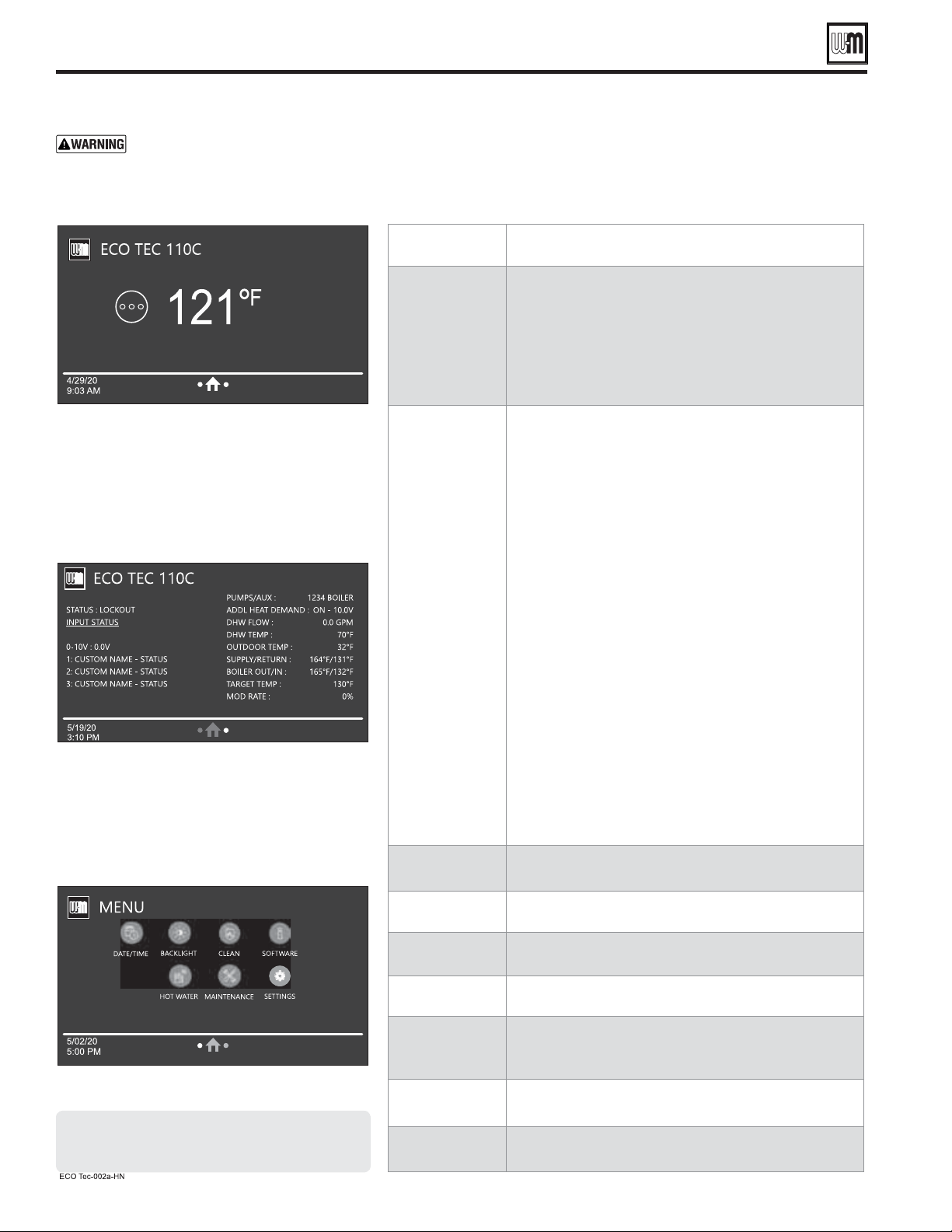
Part number 550-100-260/0520
86
ECO
®
Tec
GAS-FIRED WATER BOILER – 80/110/150/199 BOILER MANUAL
HOMEOWNER NAVIGATION menus
Failure to set correctly could
result in severe personal injury, death or substantial
property damage.
1. Access contractor menus by pressing and holding the WM
Logo for 7 seconds from the home screen.
2. See the following pages for explanations of control setting
options.
HOMEOWNER
SCREEN
Banner info
Status image
Fault name and reset button
Time/Date
Navigation buttons – 2 dots and Home
Current temperature
Target Temperature (when a priority is active)
BOILER
SETTINGS
Status: Shows the current sequence of operation status with
the active priority.
Input Status: Shows the current status of each call for heat.
0-10v: Shows the current 0-10v input value from external
device.
1-4: Shows inputs 1 through 4, what they are assigned to,
their custom names and their status. Input 4 will not show
for Combi models.
Pumps/Aux: Shows which aux/pump outputs are currently
active.
Additional Heat Demand: Shows whether AHD is off or on.
Only appears if a priority is selected to use AHD.
DHW Flow: Shows the current flow rate of the Combi DHW
in GPM. Only visible for Combi models.
DHW Temp: Shows the current temperature of the Combi
DHW sensor. Only visible for Combi models.
Outdoor Temp: Shows the current outdoor temperature sen-
sor value. Only visible if selected to use.
Supply/Return: Shows the current System Supply and System
Return temperature. Only visible if selected to use.
Boiler Out/In: Shows the current Boiler Out and Boiler In
temperatures.
Target Temp: Shows the current Target Temperature of the
active priority.
Mod Rate: Shows the modulation rate of the boiler’s blower
motor.
DATE/TIME
BUTTON
Allows user to edit the current date and time.
BACKLIGHT
Allows user to edit how bright the screen is during normal
operation and when dormant.
CLEAN
Locks the screen so nothing can be pressed for 10 seconds
while the user cleans the screen.
SOFTWARE
Displays the current software revisions of the control and
display.
HOT WATER
Allows the user to edit the Hot Water Temp of the Combi
demand, as well as enable or disable PREHEAT mode or
ECO BOOST.
MAINTENANCE
INFO
Allows the user to view contractor and maintenance informa-
tion, as well as reset the maintenance reminder when present.
SETTINGS
Allows the user to edit temperature units, screen timeout,
daylight savings time and sound effect of presses.
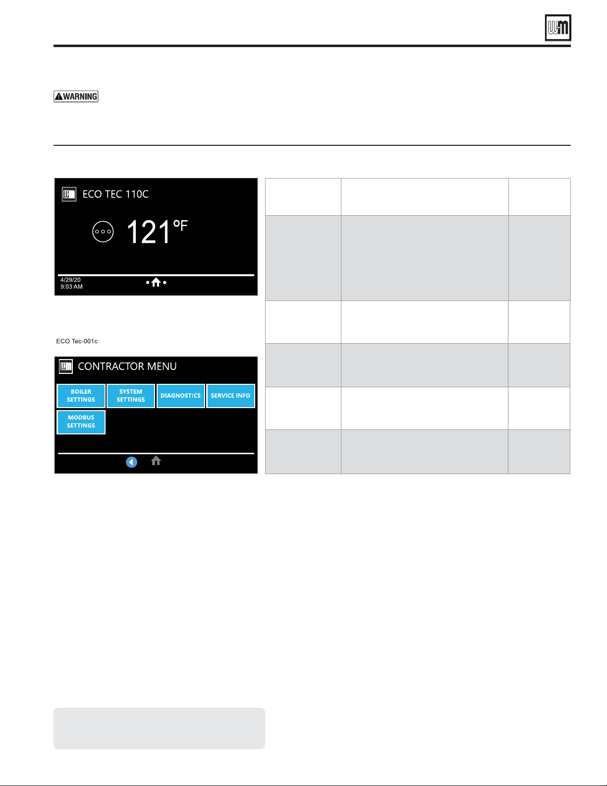
Part number 550-100-260/0520
87
ECO
®
Tec
GAS-FIRED WATER BOILER – 80/110/150/199 BOILER MANUAL
CONTRACTOR menus
Failure to set correctly could
result in severe personal injury, death or substantial
property damage.
1. Access contractor menus by pressing and holding the WM
Logo for 7 seconds from the home screen.
2. See the following pages for explanations of control setting
options.
BOILER
SETTINGS
Set/change boiler model, control type,
high altitude setting, Outdoor Temp sen-
sor requirement, manual reset high limit
and WWSD temperature settings, outdoor
sensor temp adjustment, circulator exercis-
ing, freeze protection setup, and restore to
factory default option, fuel type and blower
calibration.
See page 88
SYSTEM
SETTINGS
These settings assign Priority 1, 2 or 3 to
each of the four inputs to the control and
see an overview of assigned priorities.
See page 91
DIAGNOSTICS
Use to review current and historical infor-
mation including previous lockouts.
See page 94
SERVICE INFO
Used to set contractor contact information,
boiler information and maintenance dates.
See page 96
MODBUS
SETTINGS
Used to adjust Modbus related settings such
as Baud Rate, Parity and Stop Bits, Modbus
Address and turning Modbus on/off.
ECO Tec control menu access — accessing contractor menus
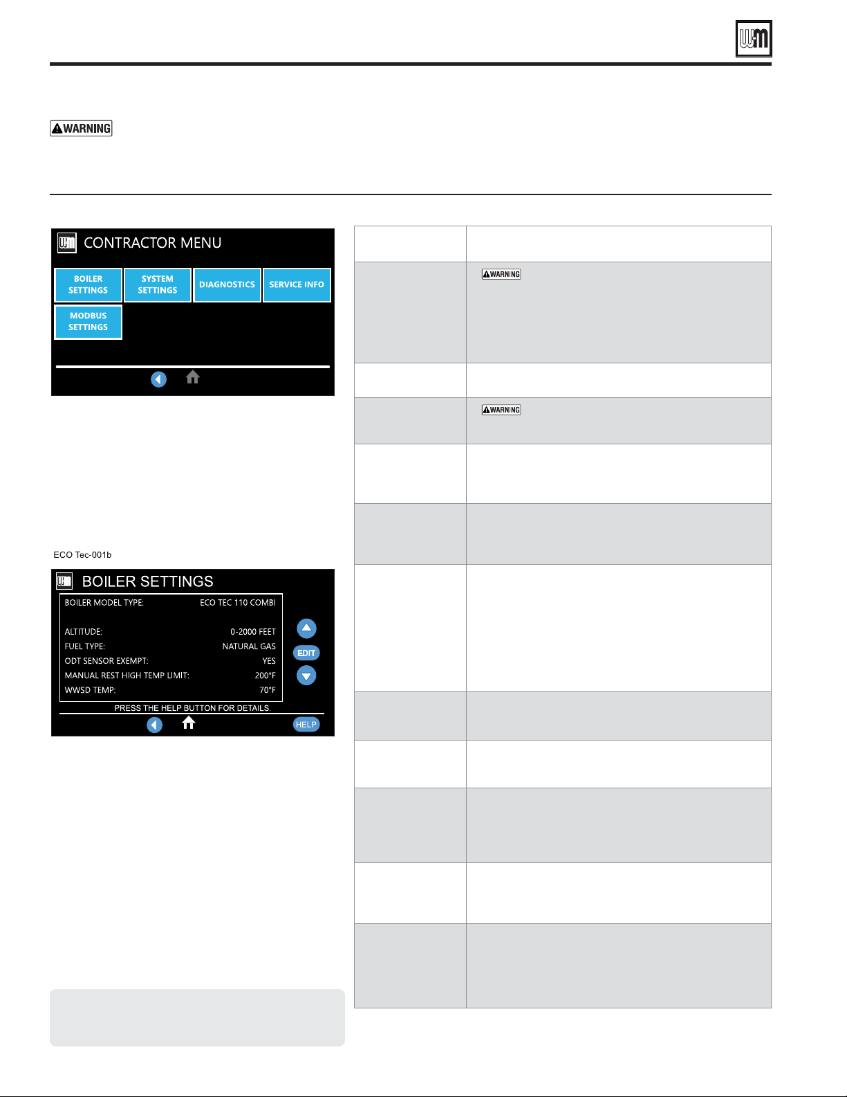
Part number 550-100-260/0520
88
ECO
®
Tec
GAS-FIRED WATER BOILER – 80/110/150/199 BOILER MANUAL
BOILER SETTINGS menu
MUST be set to correct model.
Check the boiler model against the model listed on the
boiler’s rating plate. Change the selection to the correct
model if not. Also verify the model number on the ECO
Tec control display at power-up. Failure to correct would
result in severe personal injury, death or substantial property
damage.
Must be set correctly if altitude is greater than 2,000 feet.
Settings in 500 -foot increments
MUST be correct — Select between Propane and
Natural gas is used. Follow screen instructions to change
if necessary.
Select YES only if boiler is exempt from the requirement
for outdoor reset operation stipulated in Section 303 of
the 2007 Energy Act. See information provided elsewhere
in this manual.
If boiler outlet water temperature exceeds this tempera-
ture, the ECO
Tec control will shut down the boiler
and enter lockout. Changing this setting is NOT recom-
mended.
WWSD stands for warm weather shut down. It means the
boiler will not be allowed to fire if the outdoor temperature
is greater than the WWSD setting. When the boiler is kept
off because the outdoor temperature is above WWSD,
the graphic display will show WWSD, and the boiler will
remain in standby until the outdoor temperature drops
below WWSD temperature. WWSD does not apply to
DHW systems. The outdoor sensor must be installed to
use this function.
Use this setting to calibrate the outdoor sensor when needed
to compensate for variations in lead length or other factors
that could affect total resistance in sensor circuit.
For each circulator, select whether you want the control to
automatically start the circulator and run for 10 seconds
for each 72-hour period of inactivity.
This function automatically fires the boiler at low fire and
starts the circulators chosen if the heat exchanger sensors
detect a temperature less than 45 °F. Burner is turned on
if temperature drops below 40 °F. Circulators and burner
turn off when the temperature rises above 48 °F.
Use this function to re-calibrate the blower motor for
optimal blower performance. NOTE: All calls for heat
must be off and boiler must be in "Standby" to use this
function.
This screen has two options. RESTART WIZARD keeps
all contractor information, time and date, run times and
errors, and boiler model and allows the user to restart the
wizard from the beginning. RESET FACTORY DEFAULTS
clears all information from the control including model
number and returns the control to a factory received state.
ECO Tec BOILER SETTINGS options
Failure to set correctly could
result in severe personal injury, death or substantial
property damage.
1. Access contractor menus by pressing and holding the WM
Logo for 7 seconds from the home screen.
2. See the following pages for explanations of control setting
options.
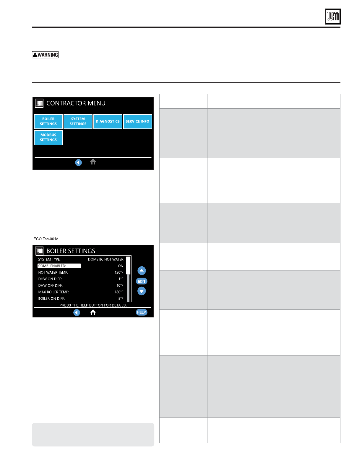
Part number 550-100-260/0520
89
ECO
®
Tec
GAS-FIRED WATER BOILER – 80/110/150/199 BOILER MANUAL
ECO
Tec PRIORITY options
Priority Setting screens
SYSTEM
TYPE
Select the system type for this PRIORITY, based on
the heating terminal units in the system (see
Figure 79, page 85). Use the CUSTOM selection to set the
control for a different system type. The factory preset val-
ues for Max Target Temp, MIN TARGET TEMP, Outdoor
Temp for Min Target and OUTDOOR TEMP FOR MAX
TARGET are chosen based on the normal best setting for
the terminal units.
TARGET
MODULATION
SENSOR
Choose SYSTEM SUPPLY or BOILER OUT to deter-
mine which will be the primary temperature sensor. The
control will modulate boiler input to reach the TARGET
temperature. (Default is SYSTEM SUPPLY only if sensor
is attached.) If system sensors are not used, boiler defaults
to using boiler outlet sensor in place of system sensor.
NOTE: Not adjustable on Combi DHW priority.
TARGET
ADJUST
Select how target temperature is calculated by control:
NONE (no reset, fixed target temperature), 0-10V (target
temperature based on analog input from remote source),
Outdoor Temp (outdoor reset operation; default set-
ting when an outdoor temperature sensor is attached).
NOTE: Not adjustable on Combi DHW priority.
MAX
TARGET
TEMP
Set Max Target Temp to the required supply water tempera-
ture for the system at design maximum heat loss (typically
180 °F for finned tube baseboard on new installations.)
NOTE: Not adjustable on Combi DHW priority.
MIN
TARGET
TEMP
MIN TARGET TEMP should equal the desired minimum
supply water temperature for the system.
This line is not shown on priorities configured as DHW
system type or Heating system type, if outdoor tempera-
ture sensor not used.
NOTE: Not adjustable on Combi DHW priority.
OUTDOOR TEMP
FOR
MIN TARGET
OUTDOOR TEMP FOR MIN TARGET is the outdoor tem-
perature at which the target temperature reaches its minimum
(MIN TARGET TEMP).
This line is not shown on priorities configured as DHW
system type or Heating system type, if outdoor tempera-
ture sensor not used.
NOTE: Not adjustable on Combi DHW priority.
OUTDOOR TEMP
FOR
MAX TARGET
OUTDOOR TEMP FOR MAX TARGET means the outdoor
temperature at which the target temperature reaches its
maximum value (MAX TARGET TEMP).
OUTDOOR TEMP FOR MAX TARGET should equal the
Outdoor Temp (outdoor design temperature) for the instal-
lation’s location.
This line is not shown on priorities configured as DHW
system type or Heating system type, if outdoor temperature
sensor not used.
NOTE: Not adjustable on Combi DHW priority.
VOLTAGE FOR
MAX TARGET
Only appears if Target Adjust or Source for Input 2 is set
to 0-10V. For Target Adjust, this sets the voltage at which
Max Target Temp temperature is requested. For Source on
Input 2, this sets the voltage that corresponds to Max Rate.
Failure to set correctly could
result in severe personal injury, death or substantial
property damage.
1. Access contractor menus by pressing and holding the WM
Logo for 7 seconds from the home screen.
2. See the following pages for explanations of control setting
options.
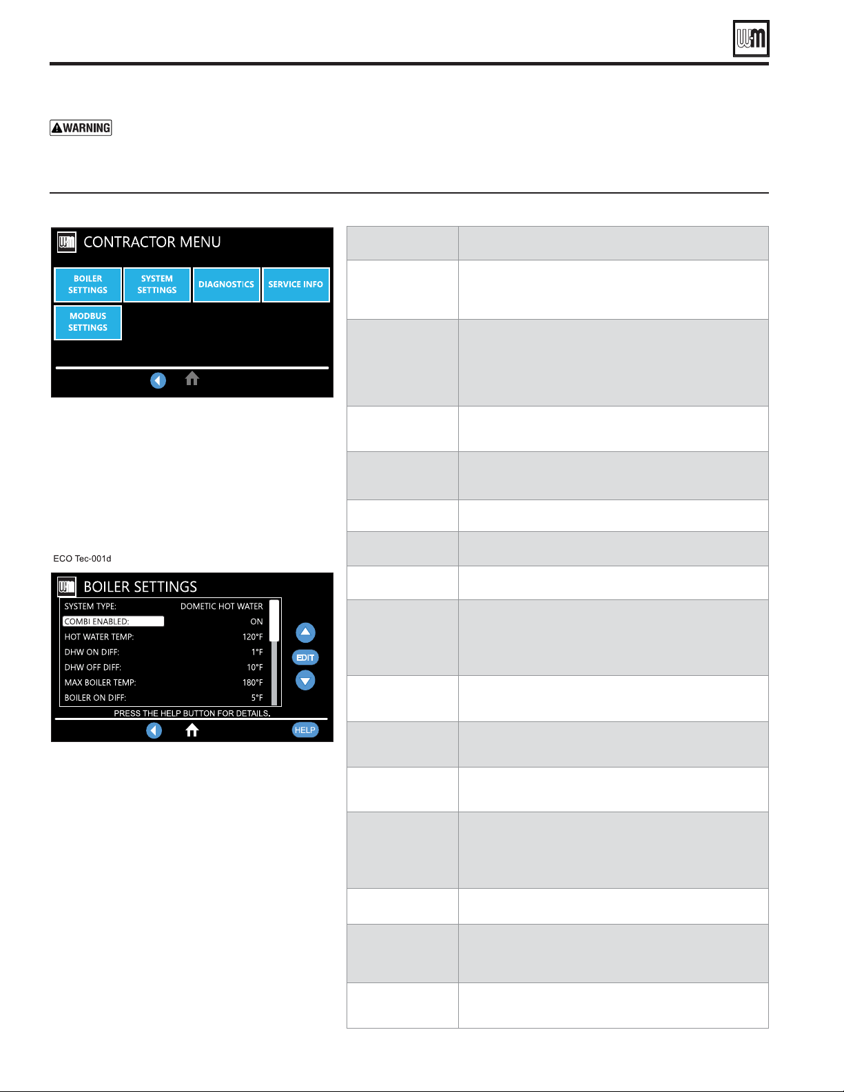
Part number 550-100-260/0520
90
ECO
®
Tec
GAS-FIRED WATER BOILER – 80/110/150/199 BOILER MANUAL
Priority Setting screens (continued)
ECO
Tec PRIORITY options
Failure to set correctly could
result in severe personal injury, death or substantial
property damage.
1. Access contractor menus by pressing and holding the WM
Logo for 7 seconds from the home screen.
2. See the following pages for explanations of control setting
options.
Voltage for Min
Target
Only appears if Target Adjust or Source for Input 2 is set
to 0-10V. For Target Adjust, this sets the voltage at which
Min Target Temp temperature is requested. For Source on
Input 2, this sets the voltage that corresponds to Min Rate.
Cold Start Error
At ignition, the difference between the Target temperature and
the current temperature is compared to this value to decide
the starting modulation rate once released to modulation. If
the difference is less than or equal to this value the modula-
tion rate will start at Min Rate. If it is greater than this value,
the control will calculate a higher modulation starting rate.
Hot Water Temp
Set target temperature to the required Combi water
temperature for the application according to design with
mixing valve.
Combi
Enabled
Select whether to enable or disable Combi functionality.
Disabling Combi functions will ignore DHW flow calls for heat
and only allow Central Heat on inputs 2 & 3 to service calls for heat.
DHW On Diff
The DHW Outlet temperature must fall below the Hot
Water Temp minus this value in order to proceed to ignition.
DHW Off Diff
If the DHW Outlet temperature exceeds the Hot Water Temp
plus this value, the burner will shut off.
PREHEAT Mode
Select the mode of PREHEAT, between Off, Economy and
High Performance.
PREHEAT Temp
Select the target temperature of the PREHEAT functionality.
The boiler will drive to this temperature until PREHEAT Off
Diff is achieved, or is interrupted by a call for heat.
PreHeat will end if Boiler Out and Boiler In exceed this
temperature.
PREHEAT Circ Diff
When in Standby, if the Boiler Out temperature falls below
the PREHEAT Temp minus the PREHEAT Circ Diff, the
boiler will activate the boiler circulator.
PREHEAT On Diff
Temperature differential that is checked when Preheat starts due
to temp falling below Circ Diff. Checks water temp to determine
whether to stop Preheat or continue to turning on burner.
PREHEAT Off Diff
While modulating on PREHEAT mode, if the Boiler Out
temperature exceeds the PREHEAT Temp plus this value,
the burner will shut off and PREHEAT mode will exit.
ECO BOOST
Select whether or not to use the ECO BOOST feature. If con-
ditions are met, the burner will continue to fire after Combi
flow ends to recover temperature within the heat exchanger.
ECO Boost will end if Boiler Out and Boiler In exceed this
temperature.
ECO BOOST
Setpoint
This setpoint is the temperature that will be driven to by
the ECO BOOST.
ECO BOOST On
Diff
If a Combi DHW call for heat ends, the Boiler Out tem-
perature is compared to the ECO BOOST Setpoint minus
ECO BOOST On Diff. If below this value, the burner will
continue to fire.
ECO BOOST Off
Diff
If firing due to ECO BOOST and the Boiler Out temperature
exceeds the ECO BOOST Setpoint plus this value, the burner
will shut off and ECO BOOST will end.
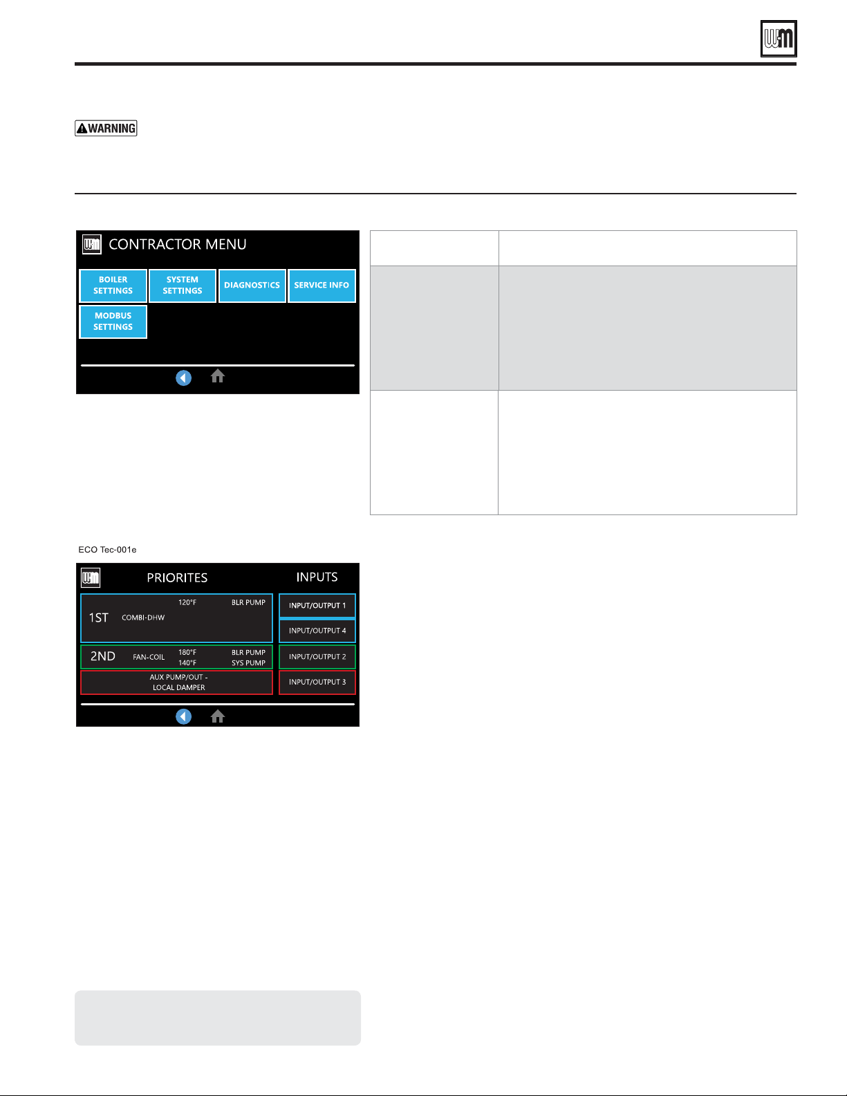
Part number 550-100-260/0520
91
ECO
®
Tec
GAS-FIRED WATER BOILER – 80/110/150/199 BOILER MANUAL
ECO
Tec Priorities and Inputs
INPUTS
Press on any of the Input squares to navigate to the Input
assignment screen. Assign priorities to inputs and the
source of Input 2.
Custom name will appear above Input/output # when a
name is entered.
PRIORITIES
Press on any of the Priorities buttons to navigate to that
priority settings.
Each box displays from left to right: the priority number,
system type, Max Target Temp on top of Min Target Temp
(when used), and populates BLR Pump and/or SYS PUMP
when selected to run these during that priority. The color
of the box corresponds to the color of the Input/output #.
System Settings
Failure to set correctly could
result in severe personal injury, death or substantial
property damage.
1. Access contractor menus by pressing and holding the WM
Logo for 7 seconds from the home screen.
2. See the following pages for explanations of control setting
options.
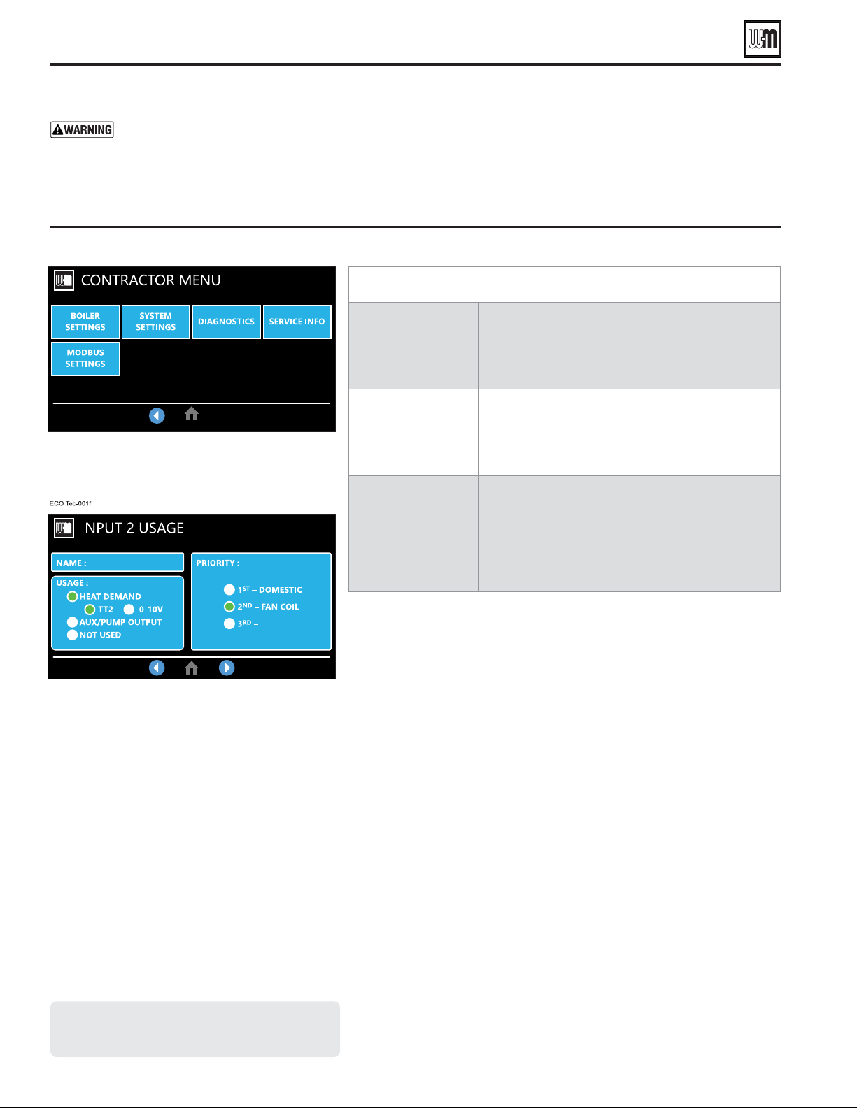
Part number 550-100-260/0520
92
ECO
®
Tec
GAS-FIRED WATER BOILER – 80/110/150/199 BOILER MANUAL
Configure Inputs and Outputs
Failure to set correctly could
result in severe personal injury, death or substantial
property damage.
1. Access contractor menus by pressing and holding the WM
Logo for 7 seconds from the home screen.
2. See the following pages for explanations of control setting
options.
NAME
Give a name to the input/output you are assigning to
help clarify the use of this priority for future reference.
USAGE
Assign whether the input is used for a Heat Demand,
Aux/pump output, or not used.
PRIORITIES
Assign which priority this input is linked to.
Usage and Priorities

Part number 550-100-260/0520
93
ECO
®
Tec
GAS-FIRED WATER BOILER – 80/110/150/199 BOILER MANUAL
AUX Pump/Output
AUX PUMP/OUTPUT operation
Failure to set correctly could
result in severe personal injury, death or substantial
property damage.
1. Access contractor menus by pressing and holding the WM
Logo for 7 seconds from the home screen.
2. See the following pages for explanations of control setting
options.
Standby
TT
Closed
Pre-
Pump
Pre-
Purge
Burner
Running
Post-
Purge
Post-
Pump
Standby
off
ON
off
See Figure 86 for explanation of
differences between the ANY TT
INPUT options.
off off off
ON
off off
Output is always energized whenever the control is powered.
Hot loop for seasonal boilers that are manually
shut down at end of season and started up at
start of heating season.
The output is energized on closure of an external switch wired to this
input and is de-energized when the external switch opens.
Hot loop for boilers whose CH is manually
shut down at end of season and started up at
start of heating season, but remain available for
local calls (DHW, etc.).
This output is energized only when outdoor temperature is below the
WWSD setting (see BOILER SETTINGS menu).
This setting is non-selectable if WWSD is set to OFF or Outdoor Temp
is not connected at initial boiler power. If Outdoor Below WWSD is
already chosen and WWSD is later set to OFF, Outdoor Below WWSD
will behave as Always On.
Hot loop for boilers whose CH is automati-
cally shut down based on outdoor temperature
(inferred heat loss), but remain on for local
calls (DHW, etc.).
The assigned output is energized if there is an input closure on this boiler.
The assigned output will de-energize once there are; no input on this
boiler, post-purge has finished and post-pump time has expired.
If the closed input is configured for a heat demand, its output will de-
energize after post-purge and post-pump.
Energize a system pump relay if pump must
run during all heating calls.
The assigned output is energized:
If there is an input closure on this boiler.
. . . . . .
RUN AUX PUMP/OUTPUT is set to YES for the priority as-
signed to the closed input.
The assigned output will de-energize once there are no input closures
on any of the network boilers, post-purge has finished, and post-pump
time has expired.
Energize a system pump relay if pump must
run only on some heat calls (such as systems
with locally-connected DHW heating).
The assigned output is energized when the boiler receives a call for
heat and starts to pre-purge.
The assigned output is de-energized once the burner is off and post-
purge is complete.
Activates if either this boiler or Additional Heat Demand is activated.
Use for interlocking with combustion air
damper, flow switch, etc.
The assigned output is de-energized once the burner is off and post-
purge is complete.
Only activates if this boiler is attempting to fire.
Use for interlocking with combustion air
damper, flow switch, etc.
SYSTEM/LOCAL DAMPER operation — start, run and stop, based on boiler status

Part number 550-100-260/0520
94
ECO
®
Tec
GAS-FIRED WATER BOILER – 80/110/150/199 BOILER MANUAL
DIAGNOSTIC menu
DIAGNOSTICS menu
Current operating status of the boiler. Prepurge, Ignition, Name of the system Type being satisfied, post purge, Warm Weather
Shut down, Trouble
Out1
Temperature of the first sensing element of the boiler’s heat exchanger outlet sensor
Temperature of the second sensing element of the boiler’s heat exchanger outlet sensor
Temperature of the first sensing element of the boiler’s Combi DHW outlet sensor
Temperature of the second sensing element of the boiler’s Combi DHW outlet sensor
BoilerIn
Temperature of the boiler’s heat exchanger inlet sensor
Temperature of the system water after the boiler loop
Temperature of the system water returning to the boiler loop
Temperature of the first sensing element of the boiler’s flue gas sensor
Temperature of the second sensing element of the boiler’s flue gas sensor
Temperature of the remote outdoor air temperature sensor
Current target temperature of the active priority.
Current operating status of the boiler. Prepurge, Ignition, Name of the system Type being satisfied, post purge, Warm Weather
Shut down, Trouble
Call for heat status on Input 1
Call for heat status on Input 2 (Input 2 can be TT1 or 0-10VDC input)
Call for heat status on Input 3
Call for heat status on Input 4
Voltage input for target adjust or modulation
External manual limit on low voltage terminal strip
External auto limit on low voltage terminal strip
Low water cutoff device (inside boiler jacket)
Limit device (inside boiler jacket) that will shut off the boiler if flue pressure becomes too high
J18 jumper circuit closed or open (flow switch, CAD, etc.)
Feedback from blower
Number indicating the presence and quality of the flame used to shut down or boost the boiler
Approximate gallons per minute water flow passing through the Combi brazed plate.
Current operating status of the boiler. Prepurge, Ignition, Name of the system Type being satisfied, post purge, Warm Weather
Shut down, Trouble
Control’s gas valve circuit status
Control’s circulator 1 relay status
Control’s circulator 2 relay status
Control’s circulator 3 relay status
Control’s circulator 4 relay status
Boiler’s circulator
Control’s signal controlling the blower speed
Additional heat demand contact status
Alarm contact status
Part number 550-100-260/0520
95
ECO
®
Tec
GAS-FIRED WATER BOILER – 80/110/150/199 BOILER MANUAL
DIAGNOSTICS menu (continued)
DIAGNOSTICS menu (continued)
Displays cumulative time the burner has been active (can be increased by user)
Displays cumulative time that Input 1 has been closed (Changes to DHW Time for Combi models).
Displays cumulative time that Input 2 has been closed (Or 0-10V t 1 volt)
Displays cumulative time that Input 3 has been closed
Displays cumulative time that Input 4 has been closed, changes to PREHEAT Time for Combi models, if configured for PREHEAT.
Displays total number of successful ignitions
Displays last 5 Proof of Ignition flame valves read by the control
Displays last 5 Stabilization flame valves read by the control
Shows the time/date stamp of the of the last factory reset performed
Shows the time/date stamp of the last known power cycle
To reset all history counters to zero: Enter the FAULT HISTORY menu. Then press the reset button. This will cause
ALL history to be deleted. To maintain history, set counters individually.
Displays cumulative ignition attempts. It is recommended that his be reset during yearly maintenance by selecting this line and
pressing the Reset button
Displays number of manual reset lockouts since last cleared
Displays number of auto reset lockouts since last cleared
Choose this to view the second most recent error recorded
Displays the type of fault that occurred
Displays time that lockout occurred
Displays date that lockout occurred
Displays what the status of the boiler was at the time of the error
Choose this to view the Boiler Temperatures at the time of the error
Choose this to view the status of the Boiler Inputs at the time of the error
Choose this to view the status of the Boiler Outputs at the time of the error
Status
Current operating status of the boiler. Prepurge, Ignition, Name of the system Type being satisfied, post purge, Warm Weather
Shut down, Trouble
Inputs Displays which inputs are presently calling for heat
Target Temp Calculated target temperature based on outdoor temp or the max target if no ODR
Modulation Displays what sensor the boiler is using to modulate from. May also indicate reason for boiler rate self-limiting.
Boiler Out Temperature of the outlet sensor on the boiler heat exchanger
Boiler In Temperature of the inlet sensor on the boiler heat exchanger
System Supply Temperature of the system water after the boiler loop
System Return Temperature of the system water returning to the boiler loop
Flue Temperature of flue gases
Outdoor Temperature of outdoor air
Blower Signal Control’s signal controlling the blower speed
Blower Speed Blower’s feedback to the control
Flame Signal Number indicating the presence and quality of the flame used to shut down or boost the boiler
DHW Out/Flow Temperature of the boiler's DHW outlet sensor and approximate flow in gallons per minute passing through the Combi brazed plate
Force Rate Used to manually force a rate during a call for heat. Choose auto for normal operation
Reset selected condition

Part number 550-100-260/0520
96
ECO
®
Tec
GAS-FIRED WATER BOILER – 80/110/150/199 BOILER MANUAL
SERVICE menus — navigation
SERVICE INFO
Use this section to enter contractor’s information, Consumer Protection (CP) number, install date and to enter an automatic notice
for maintenance (default is 12 months). Because this shows on the display, it is an automatic means of notifying the homeowner of
need for scheduled maintenance by the technician. Select RESET REMINDER to reset for the next maintenance date.
Name Contractor name to appear in maintenance reminders and during lockouts
Phone Contractor phone number
Model Displays the boiler model selected in the boiler setup
CP Number Enter the CP# of the boiler
Installed Enter the date the boiler was installed
Last Maintenance Performed Date automatically entered when Reset Reminder is chosen by contractor
Next Maintenance Due Date automatically calculated when Reset Reminder is selected by contractor
Interval Settings Contractor selects maintenance reminder frequency based on service history
Reset Reminder
Contractor selects this to update Last maintenance Date and Next Date. Homeowner uses this to ignore the reminder and
update only the Next Date.
Last Calibration Date Displays date of last calibration preformed.
SERVICE menus

Part number 550-100-260/0520
97
ECO
®
Tec
GAS-FIRED WATER BOILER – 80/110/150/199 BOILER MANUAL
Use only antifreeze listed by Weil-McLain as suitable for use with
ECO
Tec Gas Boilers. See Figure 125, page 137 for information
to obtain antifreeze through a Weil-McLain distributor.
1. Determine the freezing temperature needed (to protect
against lowest likely temperature the system water will
encounter).
2. Find the antifreeze concentration by volume needed for this
temperature from the antifreeze manufacturer’s data on the
antifreeze container.
3. Add up the volume (gallons) of all system piping and
components, including the expansion tank and boiler.
a. Boiler water content is listed in Figure 138, page 149.
b. Remember to include expansion tank water content.
4. Multiply this volume by the (percent) antifreeze needed to
find the number of gallons of antifreeze to add.
Fill and test water system
1. Fill system only after ensuring the water meets the
requirements of this manual.
2. Close manual and automatic air vents and boiler drain valve.
3. Fill to correct system pressure. Correct pressure will vary
with each application.
a. Typical cold water fill pressure for a residential system
is 12 psi.
b. Pressure will rise when boiler is turned on and system
water temperature increases. Operating pressure must
never exceed 24 PSIG.
4. For combi models only, purge domestic water up to cold water
inlet by flushing water out the drain valve (Figure 54, page 44,
Item #3). Once flushing is complete, allow water to flow
through boiler’s internal domestic water circuit by opening
a faucet. Ensure proper flow rate is obtained. If the flow
rate through several faucets seem reduced, remove and
clean internal combi filters located in the Domestic Water’s
Return Manifold; see page 134 under section Cleaning &
Maintenance for Domestic Water Inlet Manifold.
5. At initial fill and during boiler startup and testing, check
system thoroughly for any leaks. Repair all leaks before
proceeding further.
Eliminate all system leaks. Continual fresh make-
up water will reduce boiler life. Minerals can build
up in the heat exchanger, reducing heat transfer,
overheating heat exchanger, and causing heat
exchanger failure.
Purge air from water system
1. Connect a hose to the purge valve (see purge/drain valves,
Item 11, in piping diagrams beginning on page 44). Route
hose to an area where water can drain and be seen.
2. Close the boiler or system isolation valve between the purge
valve and fill connection to the system.
3. Close zone isolation valves.
4. Open quick-fill valve on cold water make-up line.
5. Open purge valve.
1. The system must be thoroughly flushed (without boiler
connected) to remove sediment. The high-efficiency heat
exchanger can be damaged by buildup or corrosion due to
sediment.
2. For zoned systems, flush each zone separately through a purge
valve. (If purge valves and isolation valves are not already
installed, install them to properly clean the system.)
3. Flush system until water runs clean and piping is free of
sediment.
Do not use petroleum-based cleaning
or sealing compounds in boiler system.
Damage to elastomer seals and gaskets in
system could occur, resulting in substantial
property damage.
Before filling the boiler and system with
water, verify the following. DO NOT ll
with soened water. Boiler corrosion can
occur.
Failure to comply could result in boiler
failure or unreliable operation.
Water chemistry
1. Maintain boiler water pH between 7.0 and 8.5. Check with
litmus paper or have chemically analyzed by water treatment
company.
2. If pH differs from above, consult local water treatment
company for treatment needed.
1. Consult local water treatment companies for unusually hard
water areas (above 7 grains hardness).
1. Filling with chlorinated fresh water should be acceptable
since drinking water chloride levels are typically less than
5 ppm.
2. Do not use the boiler to directly heat swimming pool or
spa water.
3. Do not fill boiler or operate with water containing chloride
in excess of 200 ppm.
Verify that the water chemistry meets the limitations
and requirements of all other equipment in the
system.
Startup — fill the system

Part number 550-100-260/0520
98
ECO
®
Tec
GAS-FIRED WATER BOILER – 80/110/150/199 BOILER MANUAL
6. One zone at a time, open the isolation valves. Allow water
to run through the zone, pushing out the air. Run until no
noticeable air flow is present. Close the zone isolation valves
and proceed with the next zone. Follow this procedure until all
zones are purged. Follow the same procedure to purge air from
the boiler and its internal piping.
7. Close the quick-fill water valve and purge valve and remove the
hose. Open all isolation valves. Watch that system pressure rises
to correct cold-fill pressure.
8. After the system has operated for a while, eliminate any residual
air by using the manual air vents located throughout the system.
9. If purge valves are not installed in system, open manual air vents
in system one at a time, beginning with lowest floor. Close vent
when water squirts out. Repeat with remaining vents.
10. Open automatic air vent (diaphragm-type or bladder-type
expansion tank systems only) one turn.
11. Starting on the lowest floor, open air vents one at a time until
water squirts out.
12. Repeat with remaining vents.
13. Refill to correct pressure.
X100 inhibitor is required
1. It is required that the ECO
Tec boiler have Sentinel X100 added
to the system to prevent damage to the boilers’ heat exchanger.
See Replacement Parts section at the end of this manual for
ordering information.
2. After filling the system as directed in these instructions, use a
caulking gun to inject the X100 inhibitor concentrate into the
system, or fill with the X100 in its liquid form, following the
instructions on the tube or container.
3. After adding the inhibitor to the system, allow time for the
water to circulate and mix. Then check the inhibitor level. Add
additional inhibitor if necessary.
4. See separate instructions or Weil-McLain website for suggested
guidelines to determine how much inhibitor to use.
Check/verify water chemistry
1. The system may have residual substances that could affect water
chemistry.
2. After the system has been filled and leak tested, verify water pH
and chloride concentrations are acceptable.
3. Test the pH of a sample of system water at least annually. The
pH of the water mixture must be between 7.0 and 8.5. (Or use
the Sentinel inhibitor test kit to check concentration.)
4. If pH is outside this range (or inhibitor test kit indicates low
level), the inhibitor level may not be sufficient to prevent
corrosion.
5. Verify and test antifreeze concentration, if used.
Test antifreeze concentration at least annually. If
concentration is low, add antifreeze or drain system
and refill with correct mixture.
6. Follow instructions on antifreeze container to determine the
amount of antifreeze needed.
exceed 50% by volume
concentration of antifreeze.
7. Follow the instructions on the Sentinel test kit to sample the
system water and verify inhibitor concentration.
8. Check inhibitor level after adjustments are made. Check
concentration annually.
Freeze protection (if used)
Follow these guidelines to prevent possibility
of severe personal injury, death or substantial
property damage:
before installing the new boiler.
are available online. The MSDS
contains information on potential hazards and
first aid procedures for exposure or ingestion.
. Glycol concentration and inhibitor
levels may change over time. Add antifreeze
to increase concentration if necessary. Add
inhibitor as needed to bring to acceptable level,
using inhibitor test kit to verify.
In addition to antifreeze and inhibitor, use
and maintain minimum level of Sentinel X100
inhibitor as directed on this page.
If using freeze protection fluid with automatic
fill,
. Freeze protection fluid may
leak before the water begins to leak, causing
concentration to drop, reducing the freeze
protection level.
. Antifreeze moves more sluggishly
than water and can interfere with heat transfer.
At antifreeze concentrations higher than 50%,
sludge can develop in the boiler, potentially
causing damage to the heat exchanger.
. Always drain
and flush the system thoroughly before filling
with antifreeze. Sludge, iron oxide deposits and
other sediment in the system inhibit flow and
can cause rapid breakdown of inhibitors.
Use only antifreeze recommended by Weil-
McLain.
Weil-McLain provides information for
application of the antifreeze products listed
in this document only for use in Weil-McLain
boilers. Do not apply these products or
instructions for other applications. Local codes
may require a backflow preventer or actual
disconnection from city water supply.
Startup — fill the system (continued)
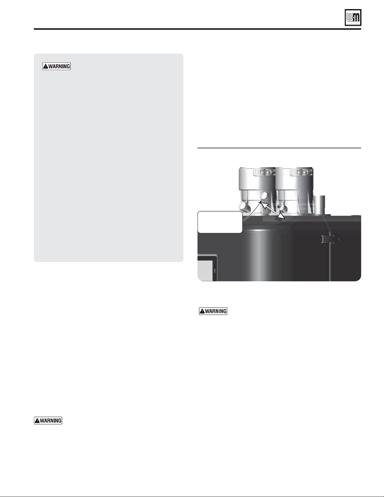
Check for gas leaks
Before starting the boiler, and during initial operation,
use a leak detector or smell near the fl oor and around
the boiler for gas odorant or any unusual odor. Remove
boiler jacket door and smell the interior of the boiler
jacket.
.
The gas valve is factory-set for the
correct outlet pressure. This setting is suitable for
natural gas and propane, requiring no fi eld adjustment.
Attempting to alter or measure the gas valve outlet
pressure could result in damage to the valve, causing
potential severe personal injury, death or substantial
property damage.
— Your propane supplier mixes
an odorant with the propane to make its presence
detectable. In some instances, the odorant can fade,
and the gas may no longer have an odor. Before startup
(and periodically thereafter), have the propane supplier
verify the correct odorant level in the gas.
Remove test port cap on vent adapter
Part number 550-100-260/0520
99
ECO
®
Tec
GAS-FIRED WATER BOILER – 80/110/150/199 BOILER MANUAL
Check thermostat circuits
1. Disconnect wires connected to the
thermostat terminals (see Field
wiring, beginning on page 58 for low voltage terminal
locations and application information). Mark the
wires before removing to avoid wiring errors when re-
connecting them
2. Close each thermostat, zone valve and/or relay in the
external circuit one at a time and check the voltmeter
reading at each wire to a ground to ensure no voltage is
being feed back into the boiler’s control module.
3.
4. If a voltage reading is measured on the incoming wires,
check and correct the external wiring.
. This could cause control
damage.
5. Once the external thermostat circuit wiring is checked and
corrected if necessary, reconnect the external thermostat
circuit wires.
Inspect/fi ll condensate system
Inspect the condensate drain line, condensate PVC fi ttings and
condensate trap. (See page 56 for component locations.)
1. Remove test port cap on vent adapter (see Figure 91 ).
2. Pour one cup full of clean water into test port.
3. Ensure condensate trap fi lled with water.
4. Reinstall test port cap on vent adapter.
The condensate trap must be fi lled with water during
all times of boiler operation to avoid fl ue gas emission
from the condensate drain line. Failure to fi ll the trap
could result in severe personal injury or death.
Startup — fi nal checks

CONTINUED AFTER NEXT PAGE
Part number 550-100-260/0520
100
ECO
®
Tec
GAS-FIRED WATER BOILER – 80/110/150/199 BOILER MANUAL
Final checks before starting boiler
❏
Read the instructions to adjust and set up the control.
❏
Verify that the boiler model is set correctly in the control, and
that it displays correctly.
❏
Verify that the boiler and system are full of water and all
system components are correctly set for operation.
❏
Verify that condensate trap is filled with water.
❏
Verify electrical connections are correct, securely attached,
and sealed at cabinet openings.
❏
Inspect vent piping and air piping for signs of deterioration
from corrosion, physical damage or sagging. Verify air piping
and vent piping are intact and correctly installed per this
manual.
To start the boiler
1. Apply power to the boiler via the field installed service switch.
2. Follow the Operating Instructions, Figure 92, page 101.
3. If this is the first time powering the boiler, please refer to
the Control section of this manual starting on page 72. The
control will prompt installer to go through our Wizard menu
setup. Please complete the Wizard setup and ensure all
connected sensors are detected and the correct boiler model
is identified. If not, determine the cause and correct before
proceeding.
If boiler does not start correctly
1. Check for loose connections, blown fuse or service switch off.
2. Are external limit controls (if used) open? Is boiler water
temperature above 200°F?
3. Are the closure switch contacts open?
4. Are thermostats set below room temperature?
5. Is gas turned on at meter and boiler?
6. Is incoming gas pressure less than the minimum values given
on page 19?
7. Are control settings correct for the application?
8. Is the warm weather shutdown activated?
9. If none of the above corrects the problem, refer to
Troubleshooting, beginning on page 114.
Check system and boiler
❏
1. Check system piping and DHW piping (Combi models only)
for leaks. If found, shut down boiler and repair immediately.
(See WARNING on pages 97 and 98 regarding failure to
repair leaks.)
2. Vent any remaining air from system using manual vents. Air
in the system will interfere with circulation and cause heat
distribution problems and noise.
❏
1. Check for gas-tight seal at every connection and seam of air
piping and vent piping.
Venting system must be sealed gas-tight to prevent
flue gas spillage and carbon monoxide emissions
which will result in severe personal injury or death.
❏
Check around the boiler and inside the boiler jacket for gas odor
following the procedure of page 57 of this manual.
If you discover evidence of any gas leak, shut down
the boiler at once. Find the leak source with bubble
test and repair immediately. Do not start boiler again
until corrected. Failure to comply could result in
severe personal injury, death or substantial property
damage.
❏
Verify boiler has been converted for propane. See page 14 for
ECO
Tec 80, 110, 150 or 199.
DO NOT attempt to
measure gas valve outlet
pressure
DO NOT adjust or attempt to measure gas valve outlet
pressure. The gas valve is factory-set for the correct outlet
pressure. This setting is suitable for natural gas and propane,
requiring no field adjustment.
Attempting to alter or measure the gas valve outlet pressure
could result in damage to the valve, causing potential severe
personal injury, death or substantial property damage.
Boilers are shipped ready to operate on natural gas ONLY.
Failure to comply could result in severe personal injury,
death or substantial property damage.
❏
1. Initiate a call for heat on one of the thermostat inputs.
2. Access the control installer menus by pressing and holding
the WM logo on the top left for 5 seconds while in the middle
"Homeowner" screen.
3. Make sure the Max firing rate is set to the maximum given
in Figures 98 and 99, pages 110 and 111. If not, adjust as
necessary. Then navigate to DIAGNOSTICS — Manual test
mode (see Figure 89, page 95) and force the firing rate to
HIGH (high fire).
4. Look at the flame through the flame inspection window. The
high fire flame should be blue and should be stable. The burner
surface should be covered with orange dots.
5.
— Remove the test port
cap from the vent flue adapter and insert a combustion test
probe.
6. Test for CO
2
(or O
2
) and for CO. The CO
2
values must comply
with Figure 94, page 103. If results are acceptable, proceed to
step 7. , follow the instructions under the“Gas Valve
Adjustment" section on page 102 or page 103 to set the throttle
screw and offset regulating screw position. See
on page 102 upper left.
Startup — final checks (continued)
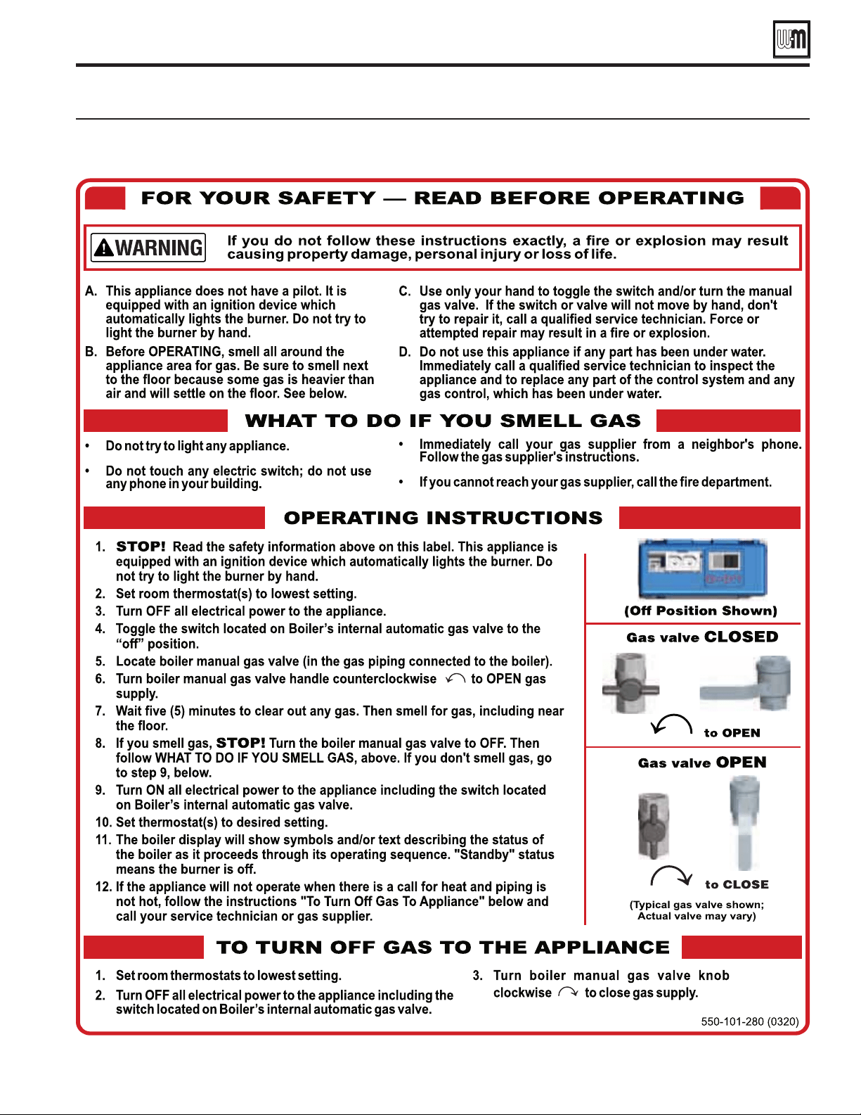
Startup — final checks (continued)
Operating instructions (WARNING -Verify that the control is set for the correct boiler model before proceeding.)
Part number 550-100-260/0520
101
ECO
®
Tec
GAS-FIRED WATER BOILER – 80/110/150/199 BOILER MANUAL
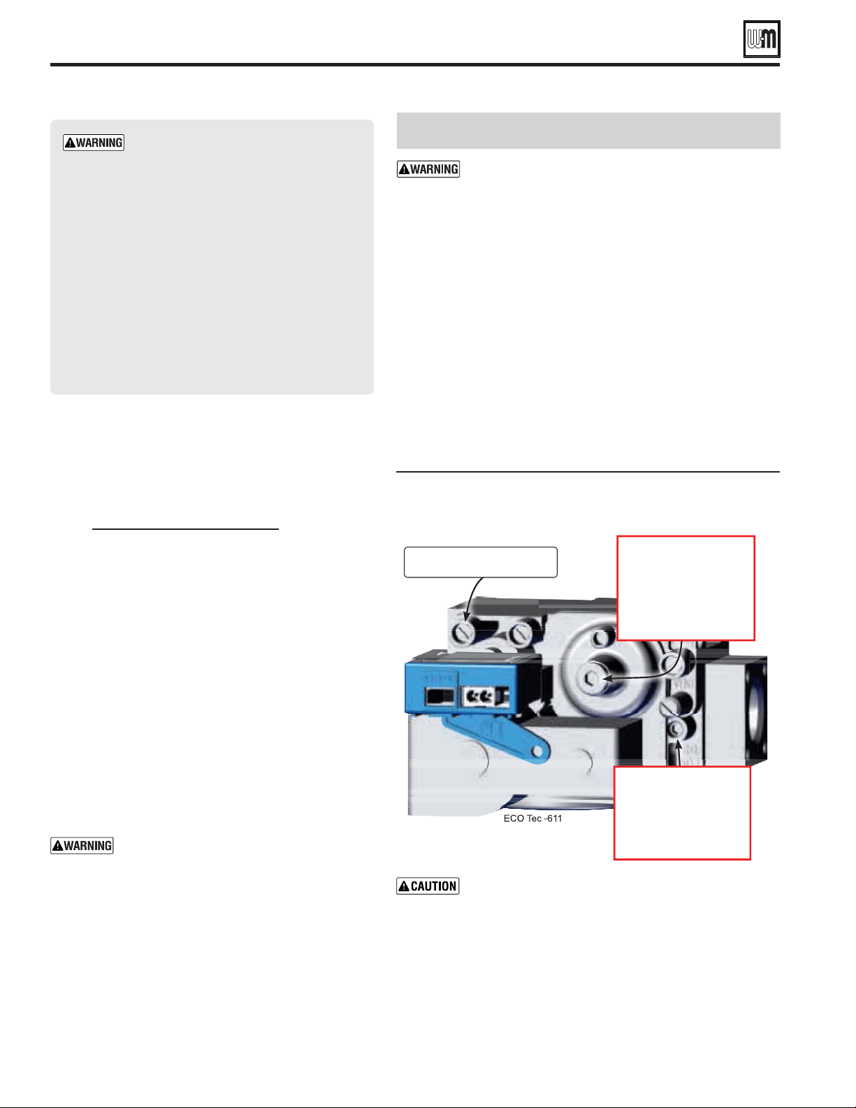
Throttle and Offset Regulating screw (ONLY for
use by a qualified technician, using calibrated
combustion test instruments)
Part number 550-100-260/0520
102
ECO
®
Tec
GAS-FIRED WATER BOILER – 80/110/150/199 BOILER MANUAL
Startup — fi nal checks (continued)
If combustion at either high or
low fi re is outside the range given
in Figure 95, page 105 , follow the
procedure given on this page or
page 105 for adjusting the gas valve.
If adjustment does not correct
the problem, then shut down the
boiler and contact your local Weil-
McLain representative. The gas valve
adjustment must be done only by a
qualifi ed technician, using calibrated
test instruments. Failure to comply
could result in severe personal injury,
death or substantial property damage.
7. Measure natural gas input:
a. Operate boiler 10 minutes. Turn off other appliances.
b. At natural gas meter, measure time (in seconds)
required to use one cubic foot of gas.
c. Calculate gas input:
3600 x 1000
= Btuh
number of seconds from step b
d. Btuh calculated should approximate input rating on
boiler rating label.
8. Use the control display to navigate to Manual test mode
(see Figure 89, page 95 ) and force the fi ring rate to LOW
(low fi re).
9. Look at the flame through the flame inspection
window. The low fi re fl ame should be stable and evenly
distributed over burner surface with a uniform orange
color.
10. Repeat the combustion test as instructed in the previous
steps.
11. Use the control display to navigate to Manual test mode
(see Figure 89, page 95 ) and force the fi ring rate to AUTO
(normal operation).
12. Reinstall the vent fl ue cap and ensure its sealed.
You must reinstall the vent fl ue cap to prevent
fl ue gas spillage into the boiler enclosure.
Failure to comply could result in severe
personal injury, death or substantial property
damage.
Gas Valve Adjustment
attempt to adjust the throttle or offset screw
unless done by a qualified technician, and with the
use of calibrated combustion test instruments. Adjust
the throttle or offset screw only as needed to meet
the combustion values given in Figure 94, page 103 .
Must confi rm correct low fi re RPM before making any
adjustments to Offset regulating screw.
1. Throttle screw adjustment is if specified
elsewhere in this manual or if combustion tests indicate the
need, as explained under “
,” page 100 .
2. Boiler behavior that might indicate a need to check combustion
values at high fi re (as per page 100 ) to verify boiler is in adjustment
include: difficulty igniting, poor flame stability at low fire,
combustion noise or high carbon monoxide values.
3. Combustion readings must be taken at both high fi re and low fi re.
DO NOT attempt an adjustment of the throttle screw at low fi re.
See Figure 93 for location of the throttle screw.
Adjust the throttle adjustment screw in small movements.
Make sure that the MAX RATE and MIN RATE for the PRIORITY that
you are planning on testing on are set to 100% and 10% respectively.
Then navigate to the MANUAL TEST MODE menu from the
DIAGNOSTICS menu ( Figure 89, page 95 ). After forcing the boiler to
HIGH FIRE insure the BLOWER SPEED has achieved the RPM listed on
Figures 98 or 99 ( Pages 110 or 111 ). Take CO
2
and CO readings and
adjust gas valve accordingly to Figures 93 and 94 allowing adequate time
for the combustion analyzer to stabilize.
Turn clockwise
to increase CO
2
. 3
Turn counter-clockwise to
decrease CO
2
. 4
Note: Must remove cover.
Throttle adjustment screw
Turn counter-clockwise
to increase CO
2
. 4
Turn clockwise to
decrease CO
2
. 3

Acceptable combustion values — measured
values must be within the ranges given below
Part number 550-100-260/0520
103
ECO
®
Tec
GAS-FIRED WATER BOILER – 80/110/150/199 BOILER MANUAL
Startup — final checks (continued)
a. If the CO
2
is HIGH, turn the throttle screw (2.5mm Allen Head)
CLOCKWISE to lower the input. Allow the boiler to stabilize and
take another reading. Continue until the desired CO
2
value is
achieved.
b. If the CO
2
is LOW, turn the throttle screw (2.5mm Allen Head)
COUNTERCLOCKWISE to increase the input. Allow the boiler to
stabilize and take another reading. Continue until the desired CO
2
value is achieved.
c. Confirm that the CO is within limits.
Low Fire
1. Adjust the boiler to (LOW) (minimum output) and allow the
boiler to stabilize. Confirm the rpm value during operation with
the Figures 98 or 99, Pages 110 or 111.
2. Remove the 4mm Allen Head cap, see Figure 93, page 102, for
Offset screw adjustment.
a. If the CO
2
is HIGH, turn the offset regulating screw 4mm Allen
Head COUNTERCLOCKWISE to lower the input. Allow the
boiler to stabilize and take another reading. Continue until
the desired CO
2
value is achieved.
b. If the CO
2
is LOW, turn the regulating screw CLOCKWISE
to increase the input. Allow the boiler to stabilize and take
another reading. Continue until the desired CO
2
value is
achieved.
c. Confirm that the CO is within limits.
d. Reinstall the 4mm Allen Head cap when adjustment is complete.
%
CO
2
CO
ppm
%
CO
2
CO
ppm
80
NG 9.25 ± 0.5 < 100 8.75 ± 0.5 < 50
LP 10.50 ± 0.5 < 150 10.15 ± 0.5 < 50
110
NG 9.25 ± 0.5 < 100 8.75 ± 0.5 < 50
LP 10.50 ± 0.5 < 150 10.15 ± 0.5 < 50
150
NG 9.25 ± 0.5 < 100 8.80 ± 0.5 < 50
LP 10.50 ± 0.5 < 150 9.90 ± 0.5 < 50
199
NG 9.25 ± 0.5 < 100 9.00 ± 0.5 < 50
LP 10.50 ± 0.5 < 150 10.40 ± 0.5 < 50
.
Values will increase about 0.2% once the door is reinstalled.
the boiler door after completing service.
CO
2
may be slightly lower and CO slightly higher.
2
must be lower than the high fire CO
2
values.
Re-check the Maximum and Minimum
CO
2
and CO rate
1. Turn off the boiler and then turn it back on and put in
Test Mode at maximum. Ensuring the CO
2
setting level has
remained unchanged and confirm that CO is within limits.
2. Reduce to minimum and re-check the minimum rate output
ensuring the CO
2
setting level has remained unchanged and
confirm that CO is within limits.
3. In the event that the CO
2
and CO cannot be obtained, please
contact your Weil-McLain representative.
4. Should you require any assistance during the set up
procedure contact your Weil-McLain representative if the
problem cannot be addressed with the information provided
in this manual.
❏
1. After the boiler has been installed, turn off the boiler.
2. Shut off the manual gas valve located on the gas line to stop
flow of fuel to the boiler.
3. Turn on the boiler. It will start the ignition sequence, but
will not light. After some time, the boiler will lockout, the
display screen will have a red banner across the screen and
will display “Ignition Fault 1”. It means that the boiler tried
to ignite without success for five (5) times and went into
Lockout mode. This means that the ignition system safety
device worked properly.
4. Clear the Lockout condition by selecting “Manual Reset” on
the Homeowner screen menu.
5. Open the manual gas valve located on the gas line to resume
fuel supply to the boiler.
❏
1. Operate the boiler on HIGH fire.
2. Using an inspection mirror, move the mirror around all
heat exchanger joints and vent pipe connections at the top
of the boiler and at the connection to the condensate dish.
Also inspect the joint between the condensate dish to heat
exchanger.
3. A leak would appear as vapor on the surface of a mirror.
Also look for signs of weepage or other indications that
there might be leakage.
4. If there is any indication of a leak at any joint, immediately
shut down the boiler.
a. If possible, tighten the retaining screws or nuts (without
over-tightening).
b. If this does not correct the problem, disassemble
the components where the leak appeared. Use the
procedures given in the Maintenance section of this
manual.
c. When disassembling components, inspect gaskets to see
if there is damage. Replace any damaged gasket.
d. Contact your Weil-McLain representative if the problem
cannot be addressed with the information provided in
this manual.
Part number 550-100-260/0520
104
ECO
®
Tec
GAS-FIRED WATER BOILER – 80/110/150/199 BOILER MANUAL
Adjust and test boiler controls
1. Follow instructions in this manual to set and verify operation
of the boiler controls.
2. Follow low water cutoff manufacturers instructions
(if used).
Have the following been done?
❏
Is the control set for the correct boiler model?
❏
Installation date and time entered into control?
❏
Boiler and heat distribution units filled with water?
❏
Water chemistry verified per page 97?
❏
Sentinel X100 corrosion inhibitor added and water tested to
be within range?
❏
Automatic air vents, if used, opened one full turn?
❏
Air purged from system?
❏
Air purged from gas piping? Piping checked for leaks?
❏
Has the condensate trap been primed and secured to drain
tube with hose clamp?
❏
Control set to correct gas type and altitude settings?
❏
Propane orifice and mixer/venturi installed for propane firing
and propane conversion label affixed to jacket?
Boilers are shipped ready to operate on
natural gas ONLY. To operate on propane,
you must follow the instructions in this
manual to install the propane venturi and
orifice. See page 14 for propane conversion.
Failure to comply could result in severe personal
injury, death or substantial property damage.
❏
Thermostat circuit wiring checked to ensure there are no
stray voltages?
❏
Followed Operating Instructions, Figure 92, page 101?
❏
Burner flame and combustion verified per page 100?
❏
Control operation for space heating, DHW (Indirect tank)
(if used), DHW (Combi model) verified per this manual?
❏
Additional field-installed controls tested as outlined by
control manufacturers? (Boiler should be operating and
should go off when controls are tested. Verify controls cause
automatic reset lockout or manual reset lockout as desired.)
❏
Additional field-installed limit control(s) set to system
temperature requirements? Balancing valves and controls
adjusted to provide design temperature to system?
❏
Flow adjusted/balanced for each zone of multiple zones
systems?
❏
Thermostat heat anticipator (if available) set properly?
❏
Boiler cycled with thermostats (and with DHW aquastat, if
installed) — Raised to highest setting and verified boiler goes
through normal startup cycle? Lowered to lowest setting and
verified boiler goes off?
❏
Combi models only: Boiler cycled with hot water faucet.
Verify boiler goes through normal start up cycle.
❏
Natural gas input measured? (page 102)
❏
Incoming gas pressure checked by connecting manometer to
gas valve ahead of boiler? (Gas pressure must be at least the
minimum values given on page 19, with boiler operating at
high fire, and no more than 14 inches (355 mm) w.c. with
boiler operating or boiler off.)
❏
Heat exchanger and vent seals checked with mirror to ensure
no leakage ?
❏
Observed several operating cycles for proper operation?
❏
Room thermostats set to desired room temperature (and
DHW aquastat, if installed, to desired DHW storage
temperature)?
❏
Combi models only: Check that the thermostatic mixing
valve is installed and is set correctly according to procedure
on page 43 and information in the paragraph at the top of
this page, and that the control is adjusted properly according
to procedure on page 90 for Control adjustment procedure.
❏
All instructions shipped with this boiler reviewed with owner
or maintenance person?
Before leaving:
❏
Fill in , page 151.
❏
Return instructions to envelope and give to owner or place
inside boiler housing.
Fill out start-up data on the Installation and Service Certificate, page 151.
Check-out/startup verification
Startup — final checks (continued)
❏
(Combi Model Only)
Ensure an ASSE 1070 Thermostatic Mixing Valve is installed
on the domestic hot water outlet pipe from the combi boiler
and is installed per the manufacturer’s instructions.
Set Boiler Control (Figure 81, page 88) to be slightly higher
than the desired temperature of the mixed hot water out of
the mixing valve
Open a faucet to allow water to flow through the combi
boiler and allow boiler to operate and modulate to the set
temperature. More than one faucet maybe required for steady
modulation and outlet temperature.
Once the combi boiler is delivering a steady temperature of
domestic hot water, follow the manufacturer’s instructions to
properly adjust and set the thermostatic mixing valve.
Make sure to check the hot water temperature at all fixtures.
Additional thermostatic mixing valves may be installed in the
system near or at fixtures. The Combi boiler’s thermostatic
mixing valve and/or other installed mixing valves may need
adjusted accordingly.

Service and maintenance schedules
Part number 550-100-260/0520
105
ECO
®
Tec
GAS-FIRED WATER BOILER – 80/110/150/199 BOILER MANUAL
(see User’s Information Manual)
Check boiler area.
Check air openings.
Check pressure/
temperature gauge.
Verify boiler jacket door is
securely in place.
Check vent piping.
Check air piping.
Check relief valve.
Check condensate drain
system.
Check automatic air vents
(if used).
Verify that domestic hot
water is being supplied
to fixtures at the correct
temperature.
Check boiler piping (gas
and water)
Operate relief valve.
(see page numbers indicated for details)
Address reported problems . . . . . . . . . . . . . . . . . . .107
Inspect boiler area . . . . . . . . . . . . . . . . . . . . . . . .107
Inspect boiler interior & jacket door gaskets. . . . . . . . . . .107
Clean condensate trap. . . . . . . . . . . . . . . . . . . . . .107
Check all piping for leaks . . . . . . . . . . . . . . . . . . . .107
Check air openings . . . . . . . . . . . . . . . . . . . . . . .108
Flue vent system and air piping . . . . . . . . . . . . . . . . .108
Check water system . . . . . . . . . . . . . . . . . . . . . . .108
Check expansion tank(s). . . . . . . . . . . . . . . . . . . . .108
Inspect ignition electrode . . . . . . . . . . . . . . . . . . . .108
Check ignition wiring. . . . . . . . . . . . . . . . . . . . . . .109
Check all boiler wiring . . . . . . . . . . . . . . . . . . . . . .109
Check control settings . . . . . . . . . . . . . . . . . . . . . .109
Perform startup and checks . . . . . . . . . . . . . . . . . . .109
Check low water cutoff . . . . . . . . . . . . . . . . . . . . .109
Check burner flame . . . . . . . . . . . . . . . . . . . . . . .109
Check flame signal. . . . . . . . . . . . . . . . . . . . . . . .109
Check blower speeds . . . . . . . . . . . . . . . . . . . . . .109
Natural gas firing rates and corresponding blower speeds . . .110
Propane gas firing rates and corresponding blower speeds . .111
Check blower speeds (continued) . . . . . . . . . . . . . . . .112
Check flue gas temperature . . . . . . . . . . . . . . . . . . .112
Manual Test Mode for Boilers . . . . . . . . . . . . . . . . . .112
3 Way Valve Test (Combi Model Only) . . . . . . . . . . . . . .112
Check Inlet gas pressure. . . . . . . . . . . . . . . . . . . . .112
Check Internal circulation pump . . . . . . . . . . . . . . . . .112
High Altitude . . . . . . . . . . . . . . . . . . . . . . . . . . .112
Check boiler relief valve . . . . . . . . . . . . . . . . . . . . .113
Review with owner . . . . . . . . . . . . . . . . . . . . . . . .113
Reinstall jacket door after servicing . . . . . . . . . . . . . . .113
Check Inlet gas pressure. . . . . . . . . . . . . . . . . . . . .112
Check Internal circulation pump . . . . . . . . . . . . . . . . .112
Combi Models Only:
Check Combi 3-way valve, DHW function and brazed plate . .113
Clean DHW brazed plate. . . . . . . . . . . . . . . . . . . . .113
Clean DHW external filter and internal Combi manifold filters . . 113
Check DHW Temperatures . . . . . . . . . . . . . . . . . . . . . 113
Follow the service and maintenance procedures given throughout this manual and in component literature
shipped with the boiler. Failure to perform the service and maintenance could result in damage to the boiler
or system. Failure to follow the directions in this manual and component literature could result in severe
personal injury, death or substantial property damage.
Annual startup and general maintenance

Part number 550-100-260/0520
106
ECO
®
Tec
GAS-FIRED WATER BOILER – 80/110/150/199 BOILER MANUAL
HANDLING CERAMIC FIBER
MATERIALS
The cover plate components, refractory
insulation, and gaskets contain ceramic
fiber
materials that have been identified as
carcinogenic, or possibly carcinogenic, to
humans
.
Ceramic fibers can be converted to
cristobalite in very high temperature
applications.
The International Agency for Research on
Cancer (IARC) has concluded, “Crystalline
silica inhaled in the form of quartz or
cristobalite from occupational sources is
carcinogenic to humans (Group 1).”:
■ Avoid breathing dust and contact with skin and eyes.
Use NIOSH certified dust respirator (N95).
This type of respirator is based on the OSHA
requirements for cristobalite at the time this
document was written. Other types of respirators
may be needed depending on the job site
conditions. Current NIOSH recommendations
can be found on the NIOSH web site at http://
www.cdc.gov/niosh/homepage.html. NIOSH
approved respirators, manufacturers, and phone
numbers are also listed on this web site.
Wear long-sleeved, loose fitting clothing, gloves,
and eye protection.
■ Handle carefully to minimize dust that could be
caused by abrasion.
■ If replacement is necessary, remove the refractory
from the boiler and place it in a plastic bag for
disposal.
■ Wash potentially contaminated clothes separately
from other clothing. Rinse clothes washer thoroughly.
■ Eye: Irrigate immediately
■ Breathing: Fresh air.
FIRST-YEAR SPECIAL INSPECTION
. This kit includes a heat exchanger cover
plate gasket, burner gasket, new ignition electrode,
and ignitor gasket. See listing in Replacement parts
section of this manual. These parts must be on hand
when you perform the first-year inspection in the
event they must be replaced.
Failure to replace the Items above when needed
could result in severe personal injury, death or
substantial property damage.
1. after the boiler is installed,
perform a first-year inspection of the boiler. This should
include the following
.
a. Inspect the heat exchanger and clean if necessary (see
page 127, for access and cleaning procedures).
b. Inspect the cover plate insulation and gasket. Replace if
not in good condition.
c. Inspect the burner and inspect carefully. Clean the burner
thoroughly using a vacuum cleaner and compressed air
if needed.
d. Make sure there is no blockage or accumulation of debris
in the burner or the burner ports. Replace the burner if
necessary.
e. Check the burner for tightness. Remove the cover plate
insulation and tighten the burner mounting screws if
needed, following the instructions on page 128.
f. Make sure to follow the inspection procedure given in
“Check exchanger and vent seals,” page 103.
g. Disconnect the condensate trap and drain lines. Inspect,
then flush thoroughly. Reinstall and refill the trap per
page 99.
2. Determine any follow-up maintenance and service needs
based on the condition of the heat exchanger and condensate
lines.
a. If the heat exchanger shows substantial fouling, or
if condensate lines show accumulation of sediment,
schedule a follow-up service call to perform the first-year
inspection again, sooner than the normal twelve months
between.
b. Heavy fouling of the exchanger or condensate lines
indicates possible combustion air contamination.
Inspect the air intake area carefully, and remove possible
contaminants. See page 20, for products to avoid.
You must eliminate causes of corrosion and
contamination to ensure reliable operation of the
boiler and system.
Annual startup
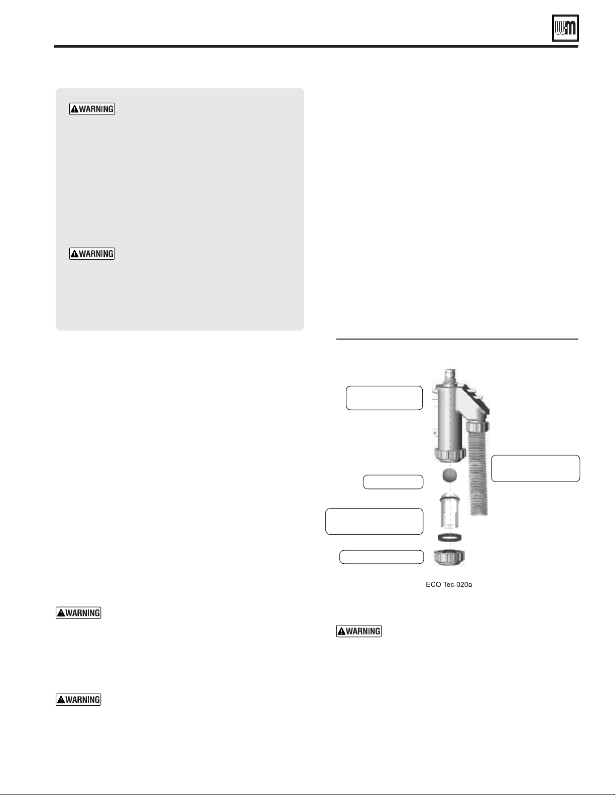
Address reported problems
1. Inspect any problems reported by owner and correct before
proceeding.
Inspect boiler area
1. Verify that boiler area is free of any combustible materials,
gasoline and other flammable vapors and liquids.
2. Verify that air intake area is free of any of the contaminants
listed on page 20 of this manual. If any of these are present
in the boiler intake air vicinity, they must be removed. If
they cannot be removed, reinstall the air and vent lines per
this manual.
Inspect boiler interior & jacket door
gaskets
1. Remove jacket door and inspect interior of boiler.
2. Visually inspect the jacket door gaskets
on front of cabinet.
Make sure all are in good condition. Obtain replacements
if any gasket is damaged.
Jacket door gaskets must be intact, and must
provide a reliable seal. Replace any damaged
gasket.
3. Remove the venturi air inlet silencer and clean if necessary.
Reinstall silencer.
4. Vacuum any sediment from the inside of the boiler and
components. Remove any obstructions.
Do not use solvents to clean any of the boiler
components. The components could be damaged,
resulting in unreliable or unsafe operation.
Clean condensate trap
1. For cleaning condensate trap, see Figure 96.
2. Remove pedestal front access panel to access the condensate
trap, if floor standing.
3. Loosen the hose clamp connecting the condensate trap to the
condensate drain tube. (See Figure 96). Pull the trap down
to disengage the condensate drain tube.
4. Remove the clean out cap and remove the trap internal parts
as shown.
5. Clean all trap components.
6. Re-assemble trap assembly. Re-install all lower gaskets.
7. Make sure the trap ball moves freely when re-inserted.
8. Fill trap with fresh water by pouring into the top of the trap
body. Continue filling slowly until water begins flowing
out the condensate drain line. Make sure the trap line is
unobstructed and flows freely or follow the procedure on
page 99 under “Fill condensate trap with water.
9. Reattach the trap to the boiler condensate outlet. Push the
trap up until fully engaged. Then retighten the hose clamp
securing the trap to the tube. Check for secure connection.
Check all piping for leaks
Eliminate all system or boiler leaks. Continual
fresh make-up water will reduce boiler life.
Minerals can build up in the heat exchanger,
reducing heat transfer, overheating heat
exchanger, and causing heat exchanger failure.
Leaking water may also cause severe property
damage.
1. Inspect all water and gas piping and verify to be leak free.
2. Look for signs of leaking lines in the system and in the
boiler and correct any problems found.
3. Check gas line using procedure on page 57.
Condensate trap cleaning
Part number 550-100-260/0520
107
ECO
®
Tec
GAS-FIRED WATER BOILER – 80/110/150/199 BOILER MANUAL
Annual startup (continued)
The boiler should be inspected and
started annually, at the beginning of the
heating season, only by a qualified service
technician. In addition, the maintenance
and care of the boiler designated in
Figure 95, page 105 and explained on
the following pages must be performed
to assure maximum boiler efficiency and
reliability. Failure to service and maintain
the boiler and system could result in
equipment failure.
Electrical shock hazard — Turn off power
to the boiler before any service operation
on the boiler except as noted otherwise in
this instruction manual. Failure to turn off
electrical power could result in electrical
shock, causing severe personal injury or
death.

Part number 550-100-260/0520
108
ECO
®
Tec
GAS-FIRED WATER BOILER – 80/110/150/199 BOILER MANUAL
Annual startup (continued)
Check air openings
1. Verify that combustion and ventilation air openings to the
boiler room and/or building are open and unobstructed.
2. Check operation and wiring of automatic combustion air
dampers, if used.
3. Verify that boiler vent discharge and air intake are clean and
free of obstructions.
Flue vent system and air piping
1. Visually inspect entire flue gas venting system and
combustion air piping for blockage, deterioration or leakage.
Repair any joints that show signs of leakage in accordance
with vent manufacturer’s instructions. Verify that air inlet
piping is connected and properly sealed.
Failure to inspect for the above conditions and
have them repaired can result in severe personal
injury or death.
Check water system
1. Verify all system components are correctly installed and
operational.
2. Check the cold fill pressure for the system. Verify it is correct
(usually around 12 PSIG).
3. Watch the system pressure as the boiler heats up (during
testing) to ensure pressure doesn’t rise too high. Excessive
pressure rise indicates expansion tank sizing or performance
problem.
4. Inspect automatic air vents and air separators. Remove air
vent caps and briefly press push valve to flush vent. Reinstall
caps. Make sure vents do not leak. Replace any leaking vents.
5. Check system water chemistry (pH, hardness and inhibitor
level). See pages 97 and 98.
Check expansion tank(s)
1. Expansion tanks provide space for water to move in and
out as the heating system water expands due to temperature
increase or contracts as the water cools.
2. See page 46 or page 50 depending on system type for
information.
3. Tank types
Closed-type — welded gas tight and located above
boiler. Tank is partially filled with water, leaving an air
cushion for expansion.
Make sure a closed-type tank is fitted with a tank
fitting, such as the B & G Tank-trol or Taco Taco-
trol. This fitting reduces gravity circulation of air-
saturated tank water back to the system and prevents
the air from bubbling up through the water as it
returns from the system.
Do not use automatic air vents in systems with
closed-type tanks. The air will escape from the
system instead of returning to the tank.
Eventually, the tank will waterlog and no longer
control pressurization. The boiler relief valve will
weep frequently.
Diaphragm- or bladder-type — welded gas tight with
a rubber membrane to separate the tank pressurizing air
and the water. May be located at any point in the system,
but preferably located on the suction side of the system
circulator.
Systems with this type of expansion tank require at
least one automatic air vent, preferably located on
top of an air eliminator, as shown in examples in
this manual.
4. If relief valve has tended to weep frequently, the expansion
tank my be water logged or undersized.
a.
— first,
check tank size to be sure it is large enough for the system.
If size is too small, add additional tank (or tanks) as
necessary to provide sufficient expansion. If tank size is
large enough, remove tank from system and check charge
pressure (usually 12 PSIG for residential applications). If
tank won’t hold pressure, membrane has been damaged.
Replace tank.
b.
— tank is most likely
waterlogged. Install a tank fitting if not already
installed. Then check fill level per fitting manufacturer’s
instructions. If fill level is correct, check tank size against
manufacturer’s instructions. Replace with a larger tank
if necessary.
Inspect ignition electrode
1. Remove the ignition electrode from the cover plate (see
Item 13, page 130). Disconnect the ground wire and ignition
cable connected to the electrode.
2. Discard the ignition electrode gasket.
3. Remove any white oxides accumulated on the ignition
electrode using steel wool. If the ignition electrode cannot
be cleaned satisfactorily, replace ignition electrode with a
new one.
4. Ignition electrode rods should be parallel and spark gap
should be 4.5mm.
5. Slide new gasket on to the ignition electrode. Reinstall
ignition electrode, making sure gasket is in good condition
and correctly positioned.
— Use a torque wrench when
tightening the two ignition electrode retainer
screws. DO NOT exceed 20 inch-pounds.
Check the seal of the ignition electrode, igniter
gasket and cover plate. Failure to comply could
cause a gas leak, resulting in severe personal injury
or death.
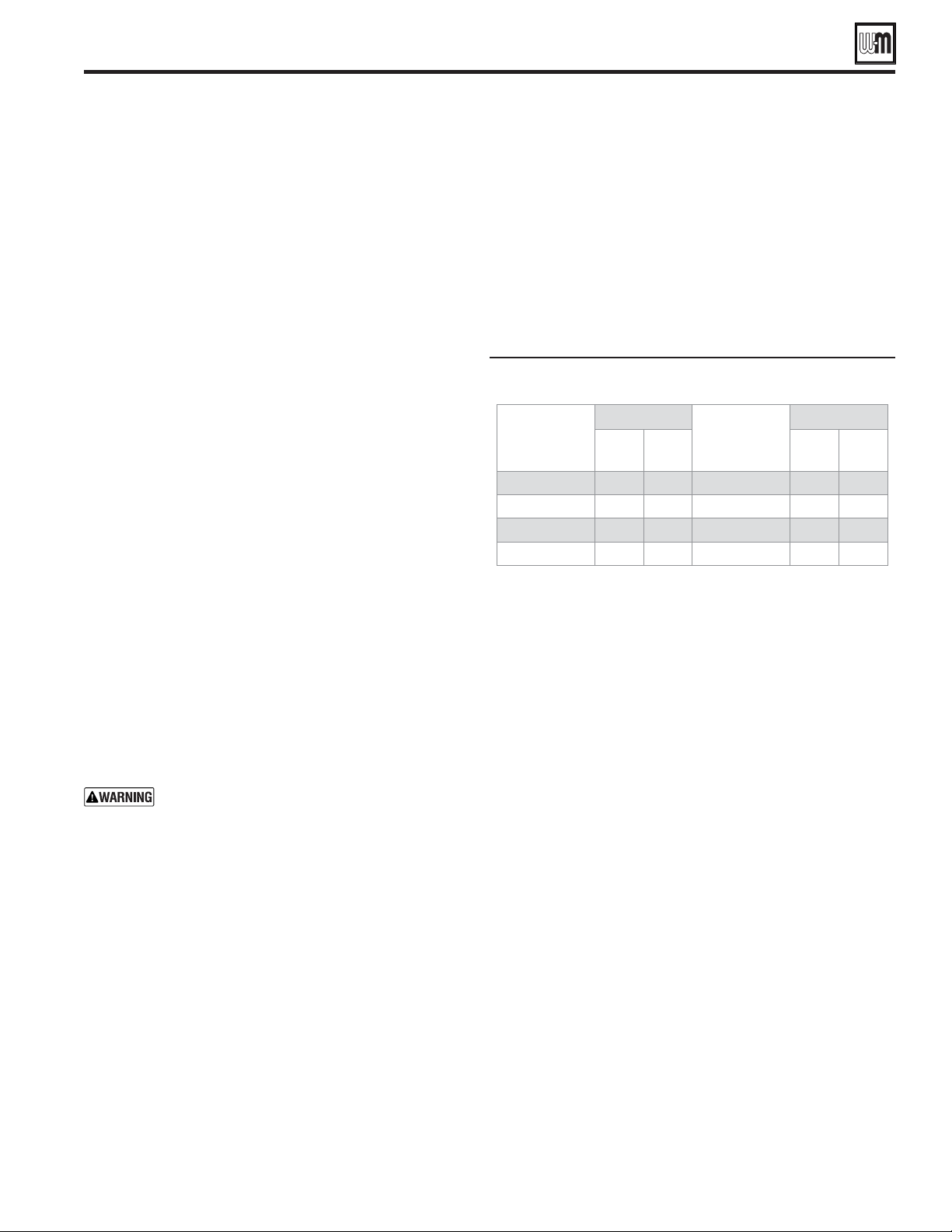
Part number 550-100-260/0520
109
ECO
®
Tec
GAS-FIRED WATER BOILER – 80/110/150/199 BOILER MANUAL
Annual startup (continued)
Check ignition wiring
1. Check ignition cable electrical resistance. A good cable will
have resistance between 950 and 1050 ohms. Replace if not
acceptable.
2. Inspect boiler ground wire from heat exchanger access cover
to ground terminal screw.
3. Verify all wiring is in good condition and securely attached.
4. Check ground continuity of wiring using continuity meter.
5. Replace ground wires if results are not satisfactory.
Check all boiler wiring
1. Inspect all boiler wiring, making sure wires are in good
condition and securely attached.
2. Verify that all connectors are securely inserted.
Check control settings
1. Use the control display to navigate through all settings.
Adjust settings if necessary.
2. Check settings of external limit controls (if any) and adjust
if necessary. Adjust as needed to accommodate the system
design.
Perform startup and checks
1. Start boiler and perform checks and tests specified in this
manual, including combustion performance check starting
on page 100.
2. Verify cold fill pressure is correct and that operating pressure
does not go too high. Adjust water pressure and expansion
tank charge pressure as necessary.
3. Complete the check-out procedure on page 104.
Check low water cutoff
Check the Low Water Cutoff for proper operation. Refer to
manufacturer’s instructions for operation and service.
Check burner flame
The boiler contains ceramic fiber materials.
Use care when handling these materials per
instructions on page 106 of this manual. Failure
to comply could result in severe personal injury.
1. Inspect flame through observation window using the
procedure on page 100.
2. If flame is unsatisfactory at either high fire or low fire, check
combustion values. If combustion is properly adjusted,
turn off boiler and allow boiler to cool down. Then remove
burner and clean it thoroughly using a vacuum cleaner or
compressed air. Do not use compressed air to clean burner
if performed inside a building.
3. To access the burner, remove the heat exchanger cover plate
following the procedure beginning on page 128.
4. If replacing the burner, ensure the burner gasket is in good
condition and correctly positioned. Follow all instructions
on page 128 or 130 to reinstall all components.
5. Restart the boiler.
6. Inspect the flame at high and low fire. If flame is still not
acceptable, check combustion values. If combustion is
properly adjusted, obtain a replacement burner from
Weil-McLain.
Check flame signal
1. Navigate to Diagnostics/Inputs on the control display
(see Figure 80, page 87 for navigation instructions and
Figure 88, page 94 for the complete Diagnostics menus).
2. e ame signal value (in micro amps) must be at least the
boost value listed in Figure97. If the ame signal drops below
this level, the control will attempt to correct by increasing the
blower speed to increase ame signal. At ignition, the proof of
ame signal must be 0.8 or greater. Typical running ame signal
should be between 4 and 6. is value will vary depending on
blower modulation, gas type, combustion settings, altitude &
age of components.
Running flame signal shutdown and boost
values
80 NG 1.5 2.0 150 NG 1.5 2.5
80 LP 1.5 2.5 150 LP 1.5 2.5
110 NG 1.5 2.0 199 NG 1.5 2.0
110 LP 1.5 2.5 199 LP 1.5 2.5
3. A low flame signal may indicate a fouled ignition electrode or
damaged ignition electrode insulation.
a. See Inspect ignition electrode, page 108 to remove and
inspect the ignition electrode .
b. If required, clean the ignition electrode as instructed.
c. If cleaning the ignition electrode does not improve, ground
wiring is in good condition, and ground continuity is
satisfactory, replace the ignition electrode .
4. If flame signal still remains low:
a. Inspect the vent and air piping.
b. Check combustion values.
c. Then inspect the heat exchanger, following the procedures
given in this manual for removal and reinstallation of the
heat exchanger cover plate and other boiler components
(see page 128).
d. Clean the exchanger as described in this manual if necessary.
Check blower speeds
1. For all installations make sure the correct altitude is set in the
boiler setup menu. The control automatically adjusts low fire,
ignition and high fire rates to compensate for high altitude
conditions.
2. Use the control display to navigate to DIAGNOSTICS/Manual
test mode (see Figure 80, page 87 for navigation instructions
and Figure 88, page 94 for the complete Diagnostics menus).
3. Set the firing rate to LOW (low fire).
4. Write down the blower RPM value, it should be within 50
of the value given in Figure 98, page 110 for Natural gas,
Figure 99, page 111 for LP propane gas, unless low fire speed
was increased based on priority need.
5. Set the firing rate to IGNITION (ignition rate).
6. Write down the blower RPM value. It should be within 50
RPM of the value listed in Figure 98, page 110 for Natural gas,
Figure 99, page 111 for LP propane gas,.
7. Set the firing rate to HIGH (high fire).
Part number 550-100-260/0520
110
ECO
®
Tec
GAS-FIRED WATER BOILER – 80/110/150/199 BOILER MANUAL
Annual startup (continued)
Natural gas
up to
2,000 feet (default settings) and high altitude (above 2,000 feet).
Model
80 110 150 199
Fuel
Type
Altitude
(feet)
%
BTU/Hr
Note 1
%
BTU/Hr
Note 1
%
BTU/Hr
Note 1
%
BTU/Hr
Note 1
Low Fire
NG
0-2,000 10% 1,900 10,200 10% 1,900 10,200 10% 1,750 15,000 10% 1,350 19,000
2,500 10% 2,030 10,200 10% 2,030 10,200 10% 1,870 15,000 10% 1,440 19,000
3,000 10% 2,070 10,200 10% 2,070 10,200 10% 1,900 15,000 10% 1,460 19,000
3,500 10% 2,100 10,200 10% 2,100 10,200 10% 1,930 15,000 10% 1,490 19,000
4,000 10% 2,140 10,200 10% 2,140 10,200 10% 1,960 15,000 10% 1,510 19,000
4,500 10% 2,170 10,200 10% 2,170 10,200 10% 1,990 15,000 10% 1,530 19,000
5,000 10% 2,210 10,200 10% 2,210 10,200 10% 2,020 15,000 10% 1,560 19,000
5,500 10% 2,240 10,200 10% 2,240 10,200 10% 2,050 15,000 10% 1,580 19,000
6,000 10% 2,300 10,200 10% 2,300 10,200 10% 2,090 15,000 10% 1,620 19,000
6,500 10% 2,350 10,200 10% 2,350 10,200 10% 2,130 15,000 10% 1,650 19,000
7,000. 10% 2,400 10,200 10% 2,400 10,200 10% 2,160 15,000 10% 1,680 19,000
7,500 10% 2,460 10,200 10% 2,460 10,200 10% 2,200 15,000 10% 1,720 19,000
8,000 10% 2,510 10,200 10% 2,510 10,200 10% 2,240 15,000 10% 1,750 19,000
8,500 10% 2,560 10,200 10% 2,560 10,200 10% 2,270 15,000 10% 1,790 19,000
9,000 10% 2,620 10,200 10% 2,620 10,200 10% 2,310 15,000 10% 1,820 19,000
9,500 10% 2,670 10,200 10% 2,670 10,200 10% 2,350 15,000 10% 1,850 19,000
10,000 10% 2,720 10,200 10% 2,720 10,200 10% 2,390 15,000 10% 1,890 19,000
10,500 10% 2,780 10,200 10% 2,780 10,200 10% 2,420 15,000 10% 1,920 19,000
11,000 10% 2,830 10,200 10% 2,830 10,200 10% 2,460 15,000 10% 1,950 19,000
Ignition
NG
0-2,000
87% 6,100 69,655 64% 6,100 69,655 48% 4,700 72,302 46% 3,530 91,000
2,500
95% 6,570 69,655 69% 6,570 69,655 52% 5,030 72,302 48% 3,680 91,000
3,000
97% 6,690 69,655 70% 6,690 69,655 53% 5,120 72,302 48% 3,730 91,000
3,500
100% 6,810 69,655 72% 6,810 69,655 54% 5,210 72,302 49% 3,770 91,000
4,000
100% 6,940 69,655 73% 6,940 69,655 54% 5,290 72,302 49% 3,810 91,000
4,500
100% 7,060 69,655 75% 7,060 69,655 55% 5,380 72,302 50% 3,850 91,000
5,000
100% 7,190 69,655 76% 7,190 69,655 56% 5,470 72,302 50% 3,890 91,000
5,500
100% 7,310 69,655 78% 7,310 69,655 58% 5,560 72,302 51% 3,930 91,000
6,000
100% 7,410 69,655 80% 7,410 69,655 58% 5,640 72,302 52% 4,010 91,000
6,500
100% 7,520 69,655 81% 7,520 69,655 59% 5,730 72,302 54% 4,080 91,000
7,000
100% 7,630 69,655 83% 7,630 69,655 60% 5,810 72,302 56% 4,160 91,000
7,500
100% 7,730 69,655 85% 7,730 69,655 61% 5,890 72,302 58% 4,230 91,000
8,000
100% 7,840 69,655 87% 7,840 69,655 62% 5,980 72,302 60% 4,300 91,000
8,500
100% 7,940 69,655 88% 7,940 69,655 63% 6,060 72,302 62% 4,380 91,000
9,000
100% 8,050 69,655 90% 8,050 69,655 64% 6,150 72,302 64% 4,450 91,000
9,500
100% 8,150 69,655 92% 8,150 69,655 65% 6,230 72,302 66% 4,530 91,000
10,000
100% 8,260 69,655 94% 8,260 69,655 66% 6,320 72,302 69% 4,600 91,000
10,500
100% 8,360 69,655 96% 8,360 69,655 67% 6,400 72,302 71% 4,670 91,000
11,000
100% 8,470 69,655 98% 8,470 69,655 68% 6,480 72,302 74% 4,750 91,000
High Fire
NG
0-2000 100% 6,830 80,000 100% 8,950 110,000 100% 8,700 150,000 100% 6,800 199,000
2,500. 100% 6,830 73,200 100% 8,950 102,097 100% 8,700 139,223 100% 6,800 184,702
3,000 100% 6,830 71,840 100% 8,950 99,987 100% 8,700 136,346 100% 6,800 180,886
3,500 100% 6,830 78,640 100% 8,950 97,878 100% 8,700 133,470 100% 6,800 177,069
4,000 100% 6,830 69,120 100% 8,950 95,768 100% 8,700 130,593 100% 6,800 173,252
4,500 100% 6,830 67,760 100% 8,950 93,658 100% 8,700 127,716 100% 6,800 169,436
5,000 100% 6,830 66,400 100% 8,950 91,549 100% 8,700 124,839 100% 6,800 165,619
5,500 100% 6,830 65,040 100% 8,950 89,439 100% 8,700 121,962 100% 6,800 161,802
6,000 100% 6,830 63,680 100% 8,910 87,708 100% 8,700 119,602 100% 6,710 157,241
6,500 100% 6,830 62,320 100% 8,880 85,949 100% 8,700 117,203 100% 6,620 152,736
7,000 100% 6,830 60,960 100% 8,840 84,190 100% 8,700 114,804 100% 6,540 148,231
7,500 100% 6,830 59,600 100% 8,810 82,430 100% 8,700 112,405 100% 6,460 143,726
8,000 100% 6,830 58,240 100% 8,780 80,671 100% 8,700 110,006 100% 6,370 139,221
8,500 100% 6,830 56,880 100% 8,740 78,912 100% 8,700 107,607 100% 6,290 134,716
9,000 100% 6,830 55,520 100% 8,710 77,152 100% 8,700 105,208 100% 6,200 130,212
9,500 100% 6,830 54,160 100% 8,670 75,393 100% 8,700 102,809 100% 6,120 125,707
10,000 100% 6,830 52,800 100% 8,640 73,634 100% 8,700 100,410 100% 6,030 121,202
10,500 100% 6,830 51,440 100% 8,600 71,874 100% 8,700 98,011 100% 5,950 116,697
11,000 100% 6,830 50,080 100% 8,570 70,115 100% 8,700 95,611 100% 5,870 112,192
Part number 550-100-260/0520
111
ECO
®
Tec
GAS-FIRED WATER BOILER – 80/110/150/199 BOILER MANUAL
Annual startup (continued)
Propane (LP) gas firing rates and corresponding blower speeds (low fire, ignition, and high fire) — for
altitudes up to
2,000 feet (default settings) and high altitude (above 2,000 feet).
Model
80 110 150 199
Fuel
Type
Altitude
(feet)
%
BTU/Hr
Note 1
%
BTU/Hr
Note 1
%
BTU/Hr
Note 1
%
BTU/Hr
Note 1
Low Fire
LP
0-2,000 10% 2,100 10,200 10% 2,100 10,200 10% 1,700 15,000 10% 1,300 19,000
2,500 10% 2,240 10,200 10% 2,240 10,200 10% 1,840 15,000 10% 1,400 19,000
3,000 10% 2,280 10,200 10% 2,280 10,200 10% 1,880 15,000 10% 1,420 19,000
3,500 10% 2,320 10,200 10% 2,320 10,200 10% 1,910 15,000 10% 1,450 19,000
4,000 10% 2,360 10,200 10% 2,360 10,200 10% 1,950 15,000 10% 1,470 19,000
4,500 10% 2,400 10,200 10% 2,400 10,200 10% 1,990 15,000 10% 1,500 19,000
5,000 10% 2,430 10,200 10% 2,430 10,200 10% 2,030 15,000 10% 1,530 19,000
5,500 10% 2,470 10,200 10% 2,470 10,200 10% 2,060 15,000 10% 1,550 19,000
6,000 10% 2,520 10,200 10% 2,520 10,200 10% 2,090 15,000 10% 1,590 19,000
6,500 10% 2,560 10,200 10% 2,560 10,200 10% 2,120 15,000 10% 1,630 19,000
7,000. 10% 2,600 10,200 10% 2,600 10,200 10% 2,150 15,000 10% 1,660 19,000
7,500 10% 2,650 10,200 10% 2,650 10,200 10% 2,180 15,000 10% 1,700 19,000
8,000 10% 2,690 10,200 10% 2,690 10,200 10% 2,220 15,000 10% 1,740 19,000
8,500 10% 2,730 10,200 10% 2,730 10,200 10% 2,250 15,000 10% 1,770 19,000
9,000 10% 2,780 10,200 10% 2,780 10,200 10% 2,280 15,000 10% 1,810 19,000
9,500 10% 2,820 10,200 10% 2,820 10,200 10% 2,310 15,000 10% 1,850 19,000
10,000 10% 2,860 10,200 10% 2,860 10,200 10% 2,340 15,000 10% 1,890 19,000
10,500 10% 2,910 10,200 10% 2,910 10,200 10% 2,370 15,000 10% 1,920 19,000
11,000 10% 2,950 10,200 10% 2,950 10,200 10% 2,400 15,000 10% 1,960 19,000
Ignition
LP
0-2,000
82% 6,200 65,871 60% 6,200 65,871 49% 4,700 74,124 45% 3,400 88,871
2,500
89% 6,630 65,871 65% 6,630 65,871 53% 5,030 74,124 48% 3,640 88,871
3,000
91% 6,740 65,871 66% 6,740 65,871 54% 5,120 74,124 49% 3,700 88,871
3,500
93% 6,850 65,871 67% 6,850 65,871 55% 5,210 74,124 50% 3,760 88,871
4,000
95% 6,970 65,871 69% 6,970 65,871 56% 5,300 74,124 51% 3,830 88,871
4,500
97% 7,080 65,871 70% 7,080 65,871 57% 5,390 74,124 52% 3,890 88,871
5,000
99% 7,200 65,871 71% 7,200 65,871 58% 5,480 74,124 52% 3,950 88,871
5,500
100% 7,310 65,871 73% 7,310 65,871 59% 5,570 74,124 54% 4,020 88,871
6,000
100% 7,440 65,871 75% 7,440 65,871 61% 5,630 74,124 54% 4,060 88,871
6,500
100% 7,570
65,871 78% 7,570 65,871 62% 5,700 74,124 56% 4,110 88,871
7,000
100% 7,710 65,871 80% 7,710 65,871 64% 5,770 74,124 57% 4,160 88,871
7,500
100% 7,840 65,871 83% 7,840 65,871 66% 5,840 74,124 58% 4,210 88,871
8,000
100% 7,970 65,871 86% 7,970 65,871 68% 5,900 74,124 59% 4,260 88,871
8,500
100% 8,100 65,871 89% 8,100 65,871 70% 5,970 74,124 60% 4,310 88,871
9,000
100% 8,230 65,871 92% 8,230 65,871 72% 6,040 74,124 62% 4,360 88,871
9,500
100% 8,370 65,871 95% 8,370 65,871 74% 6,110 74,124 63% 4,410 88,871
10,000
100% 8,500 65,871 99% 8,500 65,871 76% 6,170 74,124 65% 4,460 88,871
10,500
100% 8,490 65,871 100% 8,490 65,871 79% 6,240 74,124 66% 4,510 88,871
11,000
100% 8,400 65,871 100% 8,400 65,871 82% 6,310 74,124 68% 4,560 88,871
High Fire
LP
0-2000 100% 7,240 80,000 100% 9,450 110,000 100% 8,550 150,000 100% 6,710 199,000
2,500. 100% 7,240 73,200 100% 9,440 102,097 100% 8,530 137,208 100% 6,690 181,945
3,000 100% 7,240 71,840 100% 9,440 99,987 100% 8,530 133,794 100% 6,680 177,392
3,500 100% 7,240 78,640 100% 9,430 97,878 100% 8,520 130,379 100% 6,670 172,839
4,000 100% 7,240 69,120 100% 9,430 95,768 100% 8,520 126,964 100% 6,670 168,286
4,500 100% 7,240 67,760 100% 9,430 93,658 100% 8,510 123,549 100% 6,660 163,733
5,000 100% 7,240 66,400 100% 9,420 91,549 100% 8,500 120,135 100% 6,660 159,180
5,500 100% 7,240 65,040 100% 9,420 89,439 100% 8,500 116,720 100% 6,650 154,627
6,000 100% 7,240 63,680 100% 9,320 86,918 100% 8,380 113,919 100% 6,590 150,938
6,500 100% 7,240 62,320 100% 9,230 84,427 100% 8,280 111,072 100% 6,530 147,183
7,000 100% 7,240 60,960 100% 9,140 81,937 100% 8,170 108,224 100% 6,470 143,429
7,500 100% 7,240 59,600 100% 9,050 79,447 100% 8,060 105,377 100% 6,410 139,674
8,000 100% 7,240 58,240 100% 8,950 76,957 100% 7,960 102,529 100% 6,360 135,920
8,500 100% 7,240 56,880 100% 8,860 74,467 100% 7,850 99,682 100% 6,300 132,165
9,000 100% 7,240 55,520 100% 8,770 71,976 100% 7,740 96,834 100% 6,240 128,411
9,500 100% 7,240 54,160 100% 8,680 69,486 100% 7,640 93,987 100% 6,180 124,656
10,000 100% 7,240 52,800 100% 8,590 66,996 100% 7,530 91,139 100% 6,120 120,902
10,500 100% 7,240 51,440 100% 8,490 64,506 100% 7,420 88,291 100% 6,070 117,147
11,000 100% 7,240 50,080 100% 8,400 62,016 100% 7,320 85,444 100% 6,010 113,393

Part number 550-100-260/0520
112
ECO
®
Tec
GAS-FIRED WATER BOILER – 80/110/150/199 BOILER MANUAL
Check blower speeds (continued)
8. Write down the blower RPM value. It should be within
50 RPM of the value given in Figure 98, page 110 for
Natural gas, Figure 99, page 111 for LP propane gas.
9. If any of the values are outside the ranges listed in the
previous steps, contact the factory for technical assistance.
Minimum and maximum blower speeds can be
adjusted within limits, but changing speeds will
affect AFUE ratings.
Check flue gas temperature
1. Set the boiler to high fire. Then adjust the control display
to view flue gas temperature and boiler return temperature.
2. The flue gas temperature should be no more than 50°F
higher than the boiler return temperature. If temperature
delta is higher, cleaning the Heat exchanger may be
required. See the maintenance section starting on
page 128.
3. If the flue temperature is higher than this, shut down the
boiler, allow to cool, and follow the procedure starting on
page 128 to clean the heat exchanger.
Manual Test Mode for Boilers
1. Navigate to Manual Test Mode screen under DIAGNOSTICS
menu.
2. Generate a call for heat and wait until the burner is lit, if not
yet in operation.
3. Press EDIT and select the desired FORCE RATE. Rate will
be forced to setting for 30 minutes. Manual Test Mode resets
at end of heating demand. If time out, boiler will revert to
AUTO but will keep running if demand exist.
3 Way Valve Test (Combi Model Only)
1. Navigate to Manual Test Mode screen under DIAGNOSTICS
menu.
2. Ensure boiler is in "Standby" with no calls for heat active.
3. Press edit and select the desired position of the 3 way valve.
This is a test feature to check if the 3 way valve is operational.
4. The 3 Way Valve Actuator may be removed by the procedure
shown in Figure 122, page 135. Once removed, use the display
to change the position of the actuator and visually check to see
is the motor shaft is moving. It is normal to see the shaft slide
back in forth when the actuator is in the recessed state, but
there should be no play in the shaft when it is in the extended
state. The recess position of the shaft is for the DHW mode.
The extended position of the shaft is for the space heating
mode. When the actuator is detached, use a blunt object to
push on the 3 way valve shaft still assembled in the Sanitary
Shutter. This shaft should require some force to compress
against the valve spring. If the shaft cannot be moved, or
stuck in the compressed state, follow the procedures listed
on page 135 Cleaning & maintenance for Flow Manifold.
Annual startup (continued)
Check Inlet gas pressure
Check inlet gas pressure to limits on page 19 and at the gas inlet
pressure test port shown in Figure 93, page 102.
Check Internal circulation pump
1. Check that the circulator light turns solid orange during boiler
operation and that water flow exists.
2. Check for water leaks or signs of any water damage.
High Altitude
Note 1 for Figure 98, page 110 for Natural
gas and Figure 99, page 111 for LP
propane gas ––
The boiler will automatically derate the BTU values listed
in by 4% per 1,000 feet above sea level.
In the USA Input rates are derated 4% for each 1000
ft. above sea level, beyond 2000 ft. in accordance
with National Fuel Gas Code, ANSI Z223.1/NFPA
54 – latest edition, and/or the Natural Gas and
Propane Installation Code, CAN/CSA B149.1.
For elevations above 11,000 feet, please contact
Weil-McLain Technical Support for details
In Canada, Input rates are derated 10% for altitudes
of 2000 ft. to 4500 ft. above sea level. Please use
appropriate Fan Speed Settings for High Altitude
provided in this manual.
In Canada for elevation beyond 4500 feet, please
consult Provincial Authorities having jurisdiction
and/or local codes.

Part number 550-100-260/0520
113
ECO
®
Tec
GAS-FIRED WATER BOILER – 80/110/150/199 BOILER MANUAL
Check boiler relief valve
1. Inspect the relief valve and lift the lever to verify flow as
in the following warnings, excerpted from a relief valve
manufacturer’s warning label. Before operating any relief valve,
ensure that it is piped with its discharge in a safe area to avoid
severe scald potential.
2. Read page 48 or 51 before proceeding further.
3. Follow instructions below or perform procedures per relief
valve manufacturer’s printed instructions.
Safety relief valves should be reinspected AT LEAST
ONCE EVERY THREE YEARS, by a licensed
plumbing contractor or authorized inspection
agency, to ensure that the product has not been
affected by corrosive water conditions and to
ensure that the valve and discharge line have not
been altered or tampered with illegally. Certain
naturally occurring conditions may corrode the
valve or its components over time, rendering the
valve inoperative. Such conditions are not detectable
unless the valve and its components are physically
removed and inspected. This inspection must only be
conducted by a plumbing contractor or authorized
inspection agency — not by the owner. Failure to
reinspect the boiler relief valve as directed could
result in unsafe pressure buildup, which can result in
severe personal injury, death or substantial property
damage.
Following installation, the valve lever must be
operated AT LEAST ONCE A YEAR to ensure that
waterways are clear. Certain naturally occurring
mineral deposits may adhere to the valve, rendering
it inoperative. When manually operating the lever,
water will discharge and precautions must be taken
to avoid contact with hot water and to avoid water
damage. Before operating lever, check to see that a
discharge line is connected to this valve directing
the flow of hot water from the valve to a proper
place of disposal. Otherwise severe personal injury
or property damage may result. If no water flows,
valve is inoperative. Shut down boiler until a new
relief valve has been installed.
4. After following the above warning directions, if the relief
valve weeps or will not seat properly, replace the relief valve.
Ensure that the reason for relief valve weeping is the valve and
not over-pressurization of the system due to expansion tank
waterlogging or under-sizing.
Review with owner
1. Review the User’s Information Manual with the owner.
2. Emphasize the need to perform the maintenance schedule
specified in the User’s Information Manual (and in this
manual as well).
3. Remind the owner of the need to call a licensed contractor
should the boiler or system exhibit any unusual behavior.
4. Remind the owner to follow the proper shutdown procedure
and to schedule an annual startup at the beginning of the
next heating season.
Reinstall jacket door after
servicing
Reinstall boiler jacket door after start-up or servicing.
The boiler jacket door must be securely fastened to the
boiler to prevent boiler from drawing air from inside the
boiler room. This is particularly important if the boiler is
located in the same room as other appliances.
Inspect boiler jacket door gaskets on front of cabinet.
Gaskets must be in good condition, with no tears or gaps.
Replace if necessary.
Failure to keep the jacket door securely sealed and
fastened could result in severe personal injury or death.
Combi Models Only:
Check Combi 3-way valve, DHW
function and brazed plate
1. Cycle the 3-way valve by giving a boiler a call for heat
and then turning on a DHW call by operating a faucet.
Ensure that the valve and boiler operation changes from a
space heating call to a domestic call and hot water is being
delivered accordingly. It may be necessary to run “3 way
valve test” listed on page 112.
2. Check for water leaks around 3-way valve, brazed plate,
and brazed plate manifold fittings.
Clean DHW brazed plate
DHW/Combi brazed plate should be cleaned annually
according to the instructions starting on page 131. Cleaning
maybe required more frequently depending on water quality.
Clean DHW external filter and
internal Combi manifold filters
1. Clean the filter on the domestic inlet water external to
the boiler, installed in the near boiler piping. Follow the
manufacturer's recommended cleaning procedure.
2. Clean the Combi Manifold DHW flow switch filter and
the bypass filter according to the instructions on page 135.
Check DHW temperatures
Follow the procedure on page 104 under “Check Thermostatic
Mixing Valve Operation” to ensure proper temperatures at
all domestic hot fixtures. If a recirculation loop is installed,
check to ensure recirculation pump is working properly. Also
check aquastat, timer, and/or occupancy sensor for proper
operation, if used.
Annual startup (continued)
1. See Figure 100 for tools and kits recommended for troubleshooting
ECO
Tec boilers.
2. Check for 120VAC (minimum 102VAC to maximum 132VAC)
to boiler.
3. Check the control’s last six (6) lockout histories. (Navigate to the
DIAGNOSTICS menus.)
a. See Figure 80, page 87 for HOMEOWNER NAVIGATION
instructions and Figure 88, page 94 for the complete Diagnostics
menus.
b. In the DIAGNOSTICS menu, select FAULT HISTORY and
press the right arrow.
c. Record the fault counts, (Ignition Retries, Manual Reset Count,
Auto Reset Count).
d. Follow information at the bottom of the screen to navigate
through your lockout histories.
Tools and kits needed for troubleshooting
#2 Phillips screwdriver
Multiple uses
2.5 & 4mm Allen wrench
To adjust gas valve settings
3mm Allen wrench
For removing ignition electrode screws
8mm wrench
To remove blower
10mm wrench
To remove heat exchanger cover plate
T20 long-handled Torx
driver
To remove burner screws and mixer/venturi
Large crescent wrench
To remove gas valve
Multimeter
Measurements on sensors and electrical components
Manometer
(Inclined or digital)
Measure the INLET gas pressure to the boiler
Combustion analyzer
(Digital preferred)
Combustion testing and boiler adjustments
Contact thermometer
Checking surface temperatures of heat exchanger
and pipes
Maintenance kit
ALWAYS have this kit on hand when performing
maintenance in case replacement is required.
Check the following:
1. Make sure thermostat is calling for heat and contacts (including
appropriate zone controls) are closed. Check for 24VAC between
thermostat wire nuts and ground.
2. Make sure all external limit controls are either installed (and closed)
or temporarily jumpered for testing.
3. Make sure that connectors to the control are securely plugged in
at module and originating control.
4. Gas pressures:
Maximum: 14" (355 mm) w.c. with no fl ow (gas valve lockup
pressure).
Minimum: must be no less than the minimum values given on
page 19 while operating on high fi re.
Before calling for troubleshooting assistance, fi ll in the
“ECO
Tec” (starting on
page 152 ). Record the boiler size and Consumer Protection
(CP) number (located on the right side exterior of the
boiler jacket).
Part number 550-100-260/0520
114
ECO
®
Tec
GAS-FIRED WATER BOILER – 80/110/150/199 BOILER MANUAL
ELECTRICAL SHOCK HAZARD
.
DO NOT JUMPER DEVICES
Never jumper (bypass) any device except for
momentary testing.
REINSTALL Jacket door
The boiler jacket door must be securely fastened to
the boiler to prevent boiler from drawing air from
inside the boiler room. This is particularly important
if the boiler is located in the same room as other
appliances. Failure to keep the jacket door securely
fastened could result in severe personal injury or
death.
BEFORE SERVICING or
MAKING CONNECTIONS —
LABEL WIRES BEFORE
REMOVING
Label all wires prior to disconnection when servicing
controls. Wiring errors can cause improper and
dangerous operation.
Troubleshooting
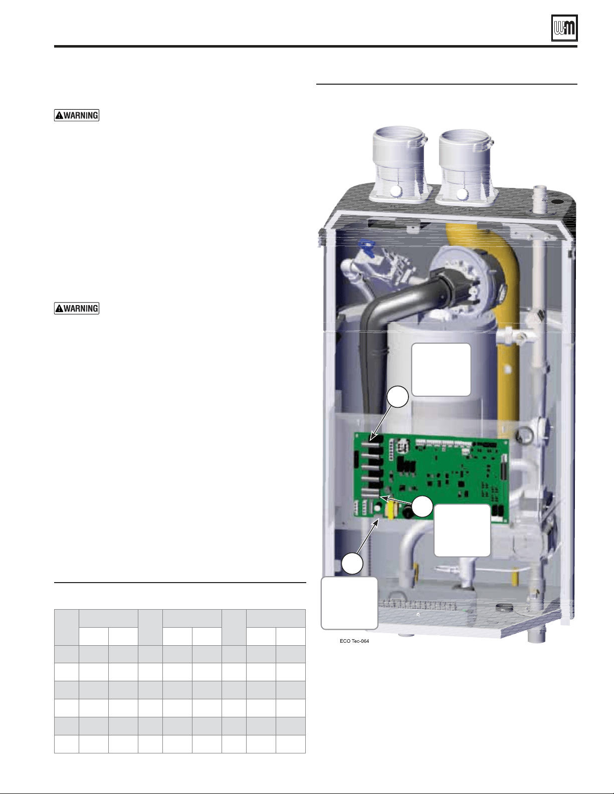
Part number 550-100-260/0520
115
ECO
®
Tec
GAS-FIRED WATER BOILER – 80/110/150/199 BOILER MANUAL
32
34265 37871
90
8504 9399
150
2517 2782
40
27834 30764
100
6847 7568
160
2091 2311
50
21630 23907
110
5545 6129
170
1744 1928
60
16944 18727
120
4517 4992
180
1461 1615
70
13372 14780
130
3698 4088
190
1229 1359
80
10629 11747
140
3043 3364
200
1038 1147
Troubleshooting (continued)
Check control fuses
ALWAYS check control fuses before replacing the
control or any major components (blower, etc.).
If one of these fuses is blown, it can prevent the
control or other components from operating.
1. Turn OFF power to boiler at external line switch. Then
remove the control access door.
2. Locate fuses using Figure 102.
3. Remove and inspect the seven (7) fuses (Items 1, 2, and 3,
Figure 102).
4. If necessary, replace one or more of the fuses:
a. Low voltage circuit fuse (Item 1) is a 3-amp 24VAC
fast-blow (Littelfuse 0287003).
b. Line voltage circuit fuses (Item 2) are 2.5-amp
120VAC fast-blow (Littelfuse 032602.5).
c. Line voltage circuit fuses (Item 3) are 4-amp 120VAC
fast-blow (Littelfuse 314004).
Do not jumper either fuse or replace with any fuse
except as specified. Failure to comply could result
in severe personal injury, death or substantial
property damage.
5. Reinstall the control access cover.
Checking temperature sensors
1. The boiler temperature sensors (Boiler In, Boiler Out, DHW
Out, Flue, Outdoor, and System Supply/Return) are all
resistance-type devices. Figure 101 shows the correct value
for the sensor at various temperatures. For dual sensors,
the temperature difference between the sensors must be no
more than 10°F.
2. Use the resistance values at 32°F, 60°F, 70°F and 212°F to
measure the sensor resistance at known temperatures (ice
point, room temperature and sea level boiling point). For
ice point and boiling point, insert the sensor in water at that
temperature. Use an ohmmeter to read resistance value.
3. To check whether the control is correctly sensing temperature,
you can use a resistance decade box. Connect the decade box
temporarily in place of a sensor and read the corresponding
temperature on the control display. The temperature should
be close to the value corresponding to the input resistance.
Sensor resistance values
Control fuses
2
1 Fuse
3-Amp
24VAC
1
1 Fuse
4-Amp
120VAC
3
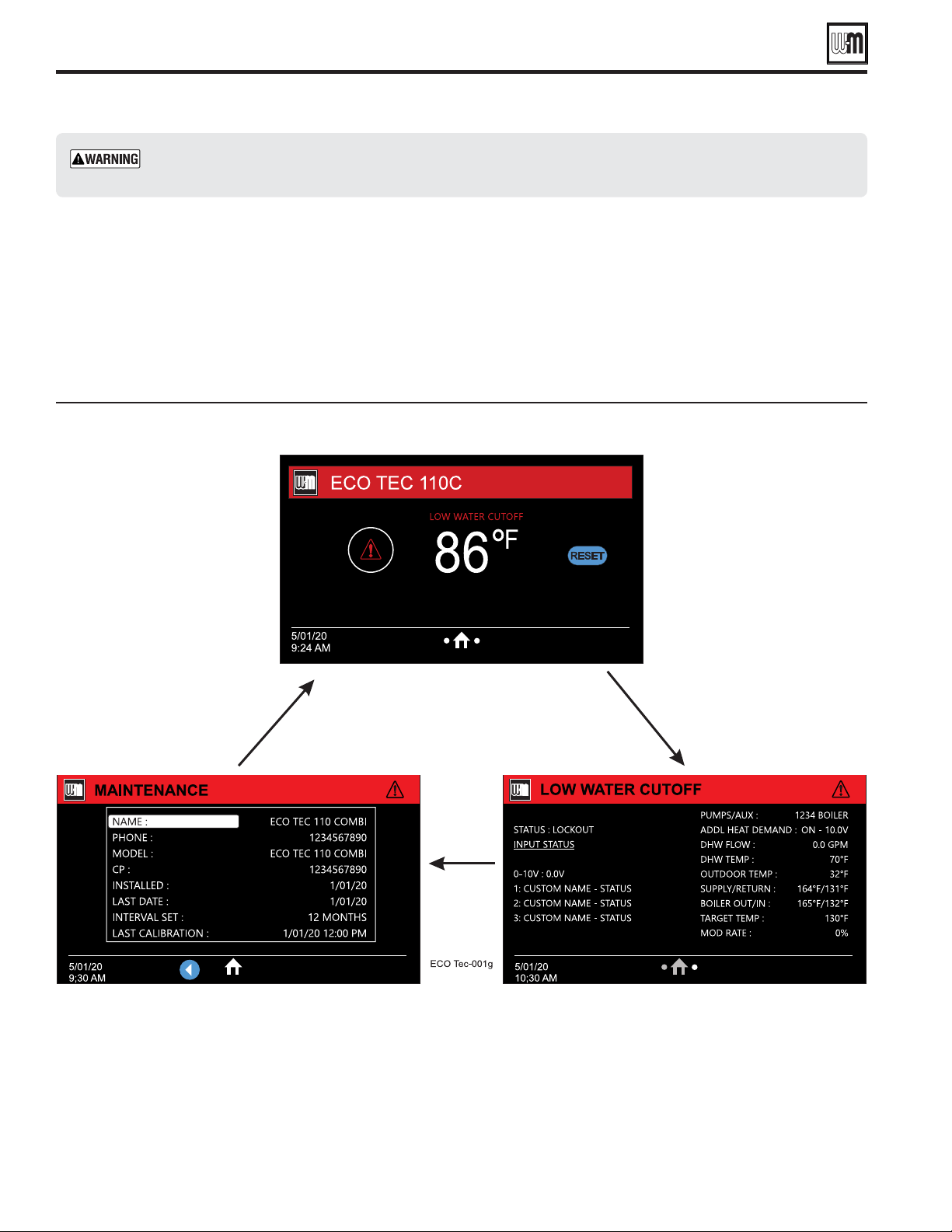
Part number 550-100-260/0520
116
ECO
®
Tec
GAS-FIRED WATER BOILER – 80/110/150/199 BOILER MANUAL
Control fault indications
1. The control provides diagnostic
information for both automatic
reset conditions and manual reset
conditions. See Figure 76, page 76 for
information available on the control
display and navigation instructions
for all menus.
2. Figure 103 shows the screen behavior
during a fault condition. The
display illustration and text below in
Figure 103 shows how to reset faults
from the Home Owners screen.
3. Figure 105, page 117 lists conditions
that will cause the control to display
a constant red screen. The boiler will
automatically restart if the condition
self-corrects or the technician uses the
control’s manual reset screens to reset.
Control display toggles when in lockout, with screen red banner
Troubleshooting (continued)
Troubleshooting suggestions —
Part number 550-100-260/0520
117
ECO
®
Tec
GAS-FIRED WATER BOILER – 80/110/150/199 BOILER MANUAL
Troubleshooting suggestions —
The Control is able to record information about the boiler’s condition at the time of the three previous faults or errors. This
information is available to view in Contractor Menus under “DIAGNOSTICS” by selecting “FAULT HISTORY” The control will
display the following information:
Information Description Action
Ignition Retries Displays cumulative ignition attempts.
It is recommended that this be reset during yearly
maintenance.
Press and reset button to reset the count or select this
parameter and press enter to reset.
Manual Reset Count Records number of lockouts that required a manual reset
since this count was last cleared.
Press the reset button to reset this count.
Auto Reset Count Records number of lockouts that have automatically reset
since this count was last cleared.
Press the reset button to reset this count.
Lockout History 1- 6 Details of present or last recorded lockout, up to 6 previous
lockouts.
Select and press the right arrow key for more details.
How to read the last 6 lockout histories:
1. 1SFTTi%*"(/045*$4wCVUUPO
2. 4FMFDUi'"6-5)*4503:wBOEQSFTTUIFSJHIUBSSPX
LFZ
3. 4FMFDUi-0$,065)*4503:wBOEQSFTTUIFright
BSSPXLFZ
4. 3FWJFXGBVMUJOGPSNBUJPOEJTQMBZFEPOTDSFFO
How to clear all lockout histories:
1. 8IJMFPOUIFi'"6-5)*4503:wTDSFFOIPMEUIF
SFTFUCVUUPOVOUJMDMFBSFE
RESTART WIZARD
The user must hold the button for a specified length of time.
Upon completion, this will erase user specific parameter
settings and take the user back through the wizard.
ONCE THIS IS CHOSEN, PREVIOUS SETTINGS
CANNOT BE RECOVERED. ENSURE THIS ACTION
IS TRULY DESIRED BEFORE CONTINUING.
RESET TO FACTORY DEFAULT
1. The user must hold the button for a specified length of
time. Upon completion, this will reset the control settings
back to factory installed settings.
ONCE THIS IS CHOSEN, PREVIOUS SETTINGS
CANNOT BE RECOVERED. ENSURE THIS ACTION
IS TRULY DESIRED BEFORE CONTINUING.
2. Reset to Factory Default can be found on the BOILER
SETTINGS menu, see Figure 80, page 87.
Troubleshooting (continued)
Troubleshooting suggestions —
Part number 550-100-260/0520
118
ECO
®
Tec
GAS-FIRED WATER BOILER – 80/110/150/199 BOILER MANUAL
Faults
Display Condition Diagnostics Corrective Action(s)
Nothing shown
on display
screen and boiler
will not respond
to call for heat
Control is not receiving 24V
power.
Check wiring for short circuit or
incorrect wiring.
Correct wiring per wiring diagram including connection of
transformer to the control.
Check 3-amp low voltage fuse
on control shown on page115.
Replace fuse with proper part found in replacement part section of
this manual. If fuse blows again recheck wiring per diagram.
Check transformer connection
to the control per wiring
diagram. Check for 24V output
of transformer.
Replace transformer if it is receiving 120VAC, but not outputting
24VAC.
Nothing is
shown in display
screen and no
other boiler
components are
operating
Control is not receiving 120V
power.
Check service switch and/
or circuit breaker to boiler is
turned on.
Turn on service switch to power boiler.
Is there 120VAC at the service
switch?
Troubleshoot and correct the power supply to the service switch.
Check for 120VAC at the line
voltage terminal block located
at J1 on the circuit board.
Correct wiring to circuit board using the wiring diagram in this
manual.
Inspect 4-amp fuse as shown
on page115. Replace if
necessary.
Replace the fuse with proper part found in the replacement part
section of this manual. If fuse blows again recheck wiring per
diagram.
Nothing is
shown on
display screen,
but boiler is
operating
Occurs if the communication
is lost from the control to the
display.
Check for loose connections
and proper pin alignment/
engagement on the control's
plug J14 and the back of the
display circuit board.
Check for continuity on the wire harness from the display to the
communications board to circuit board. See repair parts section for
proper replacement part.
Cycle power o and on and
check for operation.
Replace with new display module. See repair parts section for proper
replacement part.
TEMP RISE TOO
QUICKLY
Occurs if supply water
temperature in heat
exchanger rises faster than
10º F per second during the
rst two minutes the burner
is on.
Automatically resets after 1
minute delay or using manual
reset on display.
Manual reset is necessary
after 5 automatic resets have
occurred during the same
Priority heat demand. Reset
using manual reset screen on
display.
Verify water pipe is installed correctly per instructions in this manual.
Verify proper circulator and speed for boiler size and system
requirements.
See message displayed TEMPERATURE SENSOR and follow procedure
for loose connections.
Communication
errors
Occurs if display or main
control communications out
for 30 seconds.
Automatically resets when
communication is re-
established.
Improper connections may display the incorrect model numbers.
Check for a loose connection at the molex plug on the control and
connection on the back of the display.
Control fault Occurs when micro-
controllers on main board
have a RAM or ROM error.
Check for hardware damages. RAM or ROM errors can be reset with the manual reset option.
If problems persist, replace main board.
Troubleshooting (continued)

Troubleshooting (continued)
Troubleshooting suggestions —
Part number 550-100-260/0520
119
ECO
®
Tec
GAS-FIRED WATER BOILER – 80/110/150/199 BOILER MANUAL
Faults
Display Condition Diagnostics Corrective Action(s)
LOW WTR
CUTOFF OPEN
Occurs if internal low water
cuto contacts open.
Manual reset of control if
contacts are open.
Check for low water condition in system. Repair system as necessary
refer to piping section of this manual.
If low water condition does not exist, check Diagnostics — Inputs
screen to view status of Low Water Cuto. If shown as OPEN check
wiring between LWCO and control. If wiring is alright, remove LWCO
and Clean probe. If problem still exist, then replace the LWCO.
RETURN >
SUPPLY
Occurs if a return water
temperature is greater than
the corresponding supply
temperature by 10º F or
more
and burner has been lit for
more than 60 seconds.
Automatically resets when
condition no longer exists.
Verify proper ow direction of the boiler circulator.
Verify proper placement of system sensors. System sensors should be
on system piping not on the boiler loop.
Verify sensors are wired to correct terminal locations.
System sensors may need to be located further away from the boiler
loop connection to the system, if proximity to the boiler loop is
causing sensors to be heated inaccurately.
Boiler Output
sensor
or
Flue sensor
Occurs if dual temperature
sensors values have spread
by more that 10º F.
Automatically resets when
sensors are within 10º F.
Follow procedure for above for SHORT and OPEN sensor conditions
to properly diagnose sensor. If measured resistance values of sensors
convert to temperatures separated by more than 10º F replace the
sensor.
FLUE TEMP
TOO HIGH
Occurs if ue temperature
sensor exceeds 210º F
(Warning) or 220º F
(Lockout).
Automatic reset occurs if
temperature drops below 210º
F for 2½ minutes.
Manual reset is required if the
temperature rises above 220°
F. Reset using manual reset
screen on display.
Follow procedure above for SHORT and OPEN sensor conditions
to properly diagnose sensor. In addition inspect heat exchanger
combustion chamber and ue ways for abnormal wear or buildup.
Inspect vent system for abnormal wear or damage.
Contact Weil-McLain Technical Support.
Part number 550-100-260/0520
120
ECO
®
Tec
GAS-FIRED WATER BOILER – 80/110/150/199 BOILER MANUAL
Faults
Display Condition Diagnostics Corrective Action(s)
LIMIT OPEN
Occurs if manual or
automatic reset limit opens.
Automatic external limit will
reset 2½ minutes after external
limit device closes.
Manual limit fault must be
reset by choosing Manual
Reset on the display.
Is there an external safety device connected? If yes, trouble shoot the
external limit to determine and correct the cause that opened the
limit. Also check for loose wiring connections.
Remove the Control cover and inspect the connector
Ensure a jumper is installed across the MAN LIMIT terminals if not
using a manual reset external limit.
Ensure a jumper is installed across the AUTO LIMIT terminals if not
using a automatic reset external limit.
HIGH TEMP
LIMIT
Boiler temperature sensor
reached High Temp Limit
setting.
Reset using manual reset
screen on display.
Verify that high limit setting is at least 10° F above the maximum
target temperature plus the o dierential.
Verify all isolation valves are open and circulators are programmed
into the control properly.
The boiler circulator output and System Pump/Aux. output can be
congured to turn on or o with each priority. Refer to the Control
Setup section to congure these properly for the system.
Verify water pipe is installed correctly per instructions in this manual.
Verify proper circulator sizing for boiler size and system requirements.
See message displayed TEMPERATURE SENSOR and follow procedure
for loose connections.
FALSE FLAME
Occurs if ame is detected
when there should be no
ame.
Reset using manual reset
screen on display.
Burner may be operating too hot due to incorrect combustion.
Inspect ame and conduct combustion test.
Force boiler into high re. Check ue gases with combustion analyzer
and correct using the maintenance and startup procedure in this
manual.
Verify FLAME SIGNAL value quickly goes to zero on the DIAGNOSTICS -
INPUTS screen when the gas valve closes.
Check for ame at burner via ame current with burner o. Turn
boiler o and watch ame through observation port. If ame
continues after shut down replace gas valve.
GAS RELAY
FAULT 1-4
The control has detected
a problem with gas valve
output circuit.
Control will do automatic retry;
lockout if retry unsuccessful;
retry 1 hour after lockout —
restart if condition cleared, but
lockout requiring manual reset
if condition still present.
Requires manual reset if
control is in lockout.
If lockout reoccurs replace control.
Troubleshooting (continued)
Troubleshooting suggestions —
Part number 550-100-260/0520
121
ECO
®
Tec
GAS-FIRED WATER BOILER – 80/110/150/199 BOILER MANUAL
Faults
Display Condition Diagnostics Corrective Action(s)
IGNITION 1 FAULT
IGNITION 2 FAULT
FLAME LOSS FAULT
Boiler went through 5
ignition attempts and never
detected ame or ame
sense value never reached
minimum threshold for
boiler model.
Boiler went through 5
ignition attempts and did
not meet running ame
threshold for boiler model.
Boiler went through 5
ignition attempts and
ame value dropped below
Proof of Ignition during
stabilization time of ignition.
Automatically resets after 1 hour
or can be reset by performing
manual reset on boiler.
Check condensate trap for blockage allowing
condensate to accumulate inside heat exchanger.
Check ignition cable connection.
Fouled, worn, bent, or faulty igniter.
Fouled ignition electrode can be cleaned for additional
use with steel wool.
Worn or badly fouled ignition electrode should be
replaced with the proper repair part.
Igniter rods should be parallel with a 4.5 mm (0.177 in)
spark gap.
NOTICE: Thin white deposits on the igniter are typical,
but brown or black deposits could be the result of ue
gas recirculation. Thoroughly inspect the venting system
and termination for the possibility of leakage or ue gas
feedback into the air line.
Dirty burner and/or heat exchanger will cause high back
pressure and poor ignition.
Follow procedure in maintenance section of this manual
to clean burner and heat exchanger. Visual inspection of
ue ways may not be sucient to diagnose condition.
Check combustion settings on high and low re and
adjust per setup instructions if necessary. Check ame
signal during combustion testing according to page109
section “Check ame signal.
Check incoming gas pressure with boiler o and at high
re. Adjust within limits on rating label.
Verify correct boiler model is selected in control and
high altitude is selected for installations 5,500 above sea
level.
Check ignition cable resistance. Should measure 1000
Ohms (+/- 50 Ohms).
Check for ue pipe and intake pipe restrictions or
blockage.
Check burner fasteners and gaskets.
Check venturi gaskets and proper venturi. (Propane
models use dierent venturi’s).
AIR PRESSURE
Switch Open
Occurs when Air Pressure
connection is open.
Reset using Manual Reset screen
on display.
Check boiler size selected in control against boiler rating
label. Correct if necessary to select the proper boiler
size.
Check the factory jumper on J22 connection as seen on
Figures70,page66 and Figure71,page68.
Closure Switch fault Proof of Closure connections
on J18 a Pins 2 and 3 are
open.
Soft lockout for 4 minutes then
unlocks and checks for up to 4
minutes. If still open, soft lockout
for 4 minutes. Repeats once more
then a manual lockout.
None - Check jumper on correct pins and secure
connection.
Flow switch attached - Check correct pump is on, check
wiring to ow switch and check switch is closing.
CAD - Check voltage to damper. Check damper is
opening.
Troubleshooting (continued)
Troubleshooting suggestions —

Part number 550-100-260/0520
122
ECO
®
Tec
GAS-FIRED WATER BOILER – 80/110/150/199 BOILER MANUAL
Troubleshooting (continued)
Troubleshooting suggestions —
Faults
Display Condition Diagnostics Corrective Action(s)
Configuration fault Conguration data in the
control safety micro does
not match that in the
control’s application micro.
Correct the invalid conguration
information.
Reconrm all settings within the Control Settings screen.
Cycle power to the unit.
Perform a factory reset by going to Diagnostics – Control
Settings – Factory Default Reset and follow the on-
screen instructions.
DHW Outlet > Boiler Out *Combi Only*
DHW Outlet > Boiler Outlet
+ 10°F and burner has been
ring for at least 30 seconds.
Clears when the DHW Outlet
sensor < Boiler Outlet sensor plus
7°F.
Ensure appropriate water ow is being delivered by the
installed circulators.
Check appropriate valves are open.
Check 3-way valve is operating correctly.
Internal Clock Fault Occurs when the internal
clock of the control is out
of sync.
Clears when the control sees
a valid clock count within the
control.
Cycle power of the boiler.
Check the wiring of the display.
If problem persists, replace display.
Supply 60F > Return Occurs if either Boiler Out
temperatures are greater
than Boiler In temperature
by more than 60F or the
burner has been on for less
than 2 minutes.
If this condition occurs when
the burner has been on for
more than 2 minutes, the
burner stops ring but no
message or lockout occurs.
The rst time a lockout occurs,
the time to clear is 2 minutes
30 seconds. The second time a
lockout occurs it’s a 3 minutes 30
second lockout. The third time, its
4 minutes 30 seconds, the fourth
time its 5 minutes 30 seconds.
The fth time its 6 minutes 30
seconds.
The system will retry, indenitely,
every 6 minutes 30 seconds as
long as the temperatures return
to being < 60 degrees.
If the burner rst for at least 2
minutes without the temperature
dierence exceeding 60 degrees,
the time condition for the >
60 degree soft lockout is reset
back to the minimum value of 2
minutes 30 seconds.
Ensure proper water ow is present through boiler.
Ensure circulators are sized correctly per the system
installation and are installed correctly.
Check wiring to circulators.
For Combi applications, add a pre-pump time to the
Combi priority to mix and circulate water to reduce
chances of this fault occurring.
Temperature Sensor
Flue 1 Sensor Open
Flue 1 Sensor Short
Flue 2 Sensor Open
Flue 2 Sensor Short
Boiler Out 1 Sensor Open
Boiler Out 1 Sensor Short
Boiler Out 2 Sensor Open
Boiler Out 2 Sensor Short
Boiler In Sensor Open
Boiler In Sensor Short
Specied sensor is sensed as
Open/Short.
Clears automatically when sensor
is no longer Open/Short.
Check for loose or damaged wires on the designated
sensor and at the control board.
Replace appropriate sensor.
If issues persist, replace control.
Blower Fault 1 Blower does not reach
zero RPM within 4 minutes
when mode is Standby or
Prepump.
Clears automatically after 1 hour. Check for loose or disconnected low voltage wires
to blower motor. Inspect low voltage blower motor
harness.

Part number 550-100-260/0520
123
ECO
®
Tec
GAS-FIRED WATER BOILER – 80/110/150/199 BOILER MANUAL
Troubleshooting (continued)
Troubleshooting suggestions —
Faults
Display Condition Diagnostics Corrective Action(s)
Blower Fault 2 Blower unable to reach
required pre-purge speed or
ignition speed.
Blower failed to complete
calibration within 4 minutes
Clears automatically after 1 hour. Check for loose or damaged wires on high voltage and
low voltage blower motor harnesses.
Re-calibrate blower motor in Boiler Settings menu
Blower Fault 3 Blower is outside of
minimum or maximum
speed for 10 seconds.
1 hour automatic reset Check for loose or damaged wires on high voltage and
low voltage blower motor harnesses.
Re-calibrate blower motor in Boiler Settings menu.
Voltage Too High
Voltage Too Low
No Voltage Detected
Voltage Conguration
jumper on J6 installed
incorrectly. 24VAC jumper
installed when should be
120VAC.
120VAC jumper installed
when it should be 24VAC.
No jumper installed
Clears when correct jumper
conguration is installed on J6
Ensure the J6 connector is rmly inserted.
Check the connector on J6 on the control board. It
should match what is specied for this product.
Check incoming voltage on the main power to the
boiler, as well as across each jumper of the J6 connector.
Hardware A2D Fault The analog reading of the
internal voltage reference on
U1 read out of range 2 times
in a row.
Clears when the analog internal
voltage reference is within range.
Power cycle the boiler.
If problems persist, replace the control.
Flame Circuit Fault When the digital ame
input does not sense the
circuit to have discharged
appropriately.
Unit receives manual reset. Power cycle the boiler.
If problems persist, replace the control

Part number 550-100-260/0520
124
ECO
®
Tec
GAS-FIRED WATER BOILER – 80/110/150/199 BOILER MANUAL
Troubleshooting (continued)
Troubleshooting suggestions —
Warnings
Display Condition Diagnostics Corrective Action(s)
Supply Sensor Occurs when Supply Sensor
are chosen as the Target
Modulation sensors and
the Boiler In sensor is either
open or short.
Clears warning when a valid
sensor is detected.
Check all the temperature readings of the boiler on the
DIAGNOSTICS - TEMPERATURES menu to determine if
any sensors are currently displayed as SHORT or OPEN.
Compare this to the boiler temperatures recorded in
the DIAGNOSTICS - ERRORS - LOCKOUT HISTORY # -
TEMPERATURES during the last several lockout conditions.
Determine which sensors are suspect and measure their
resistance value and compare it to the values shown in
Figure101,page115. If the resistance values are incorrect
replace the temperature sensor. Refer to repair parts section
for proper part number.
Check wire harness for loose connections and pin
engagement at sensor connection, chassis mount
connection through control housing, and the control.
Unplug connection at sensor and at control and check
continuity between ends.
If problem persists after checking Items above, replace
control. Refer to repair parts section for kit number.
Return Sensor Occurs when Return Sensor
are chosen as the Target
Modulation sensors and the
Boiler out sensor is either
open or short.
Clears warning when a valid
sensor is detected.
Check all the temperature readings of the boiler on the
DIAGNOSTICS - TEMPERATURES menu to determine if
any sensors are currently displayed as SHORT or OPEN.
Compare this to the boiler temperatures recorded in
the DIAGNOSTICS - ERRORS - LOCKOUT HISTORY # -
TEMPERATURES during the last several lockout conditions.
Determine which sensors are suspect and measure their
resistance value and compare it to the values shown in
Figure101,page115. If the resistance values are incorrect
replace the temperature sensor. Refer to repair parts section
for proper part number.
Check wire harness for loose connections and pin
engagement at sensor connection, chassis mount
connection through control housing, and the control.
Unplug connection at sensor and at control and check
continuity between ends.
If problem persists after checking Items above, replace
control. Refer to repair parts section for kit number.
DHW Outlet Sensor *Combi Only*
The DHW Outlet sensor read
invalid.
Clears warning when DHW
Outlet sensors both read as
valid.
Check all the temperature readings of the boiler on the
DIAGNOSTICS - TEMPERATURES menu to determine if
any sensors are currently displayed as SHORT or OPEN.
Compare this to the boiler temperatures recorded in
the DIAGNOSTICS - ERRORS - LOCKOUT HISTORY # -
TEMPERATURES during the last several lockout conditions.
Determine which sensors are suspect and measure their
resistance value and compare it to the values shown in
Figure101,page115. If the resistance values are incorrect
replace the temperature sensor. Refer to repair parts section
for proper part number.
Check wire harness for loose connections and pin
engagement at sensor connection, chassis mount
connection through control housing, and the control.
Unplug connection at sensor and at control and check
continuity between ends.
If measured resistance values of sensors convert to
temperatures separated by more than 10°F replace the
sensor.
If problem persists after checking Items above, replace
control. Refer to repair parts section for kit number.
Part number 550-100-260/0520
125
ECO
®
Tec
GAS-FIRED WATER BOILER – 80/110/150/199 BOILER MANUAL
Troubleshooting (continued)
Troubleshooting suggestions —
Warnings
Display Condition Diagnostics Corrective Action(s)
Outdoor
Sensor
Error
Outdoor temperature sensor
short or OPEN.
Will automatically reset if the
condition clears.
Warning only. Max Target Temp is
targeted until Outdoor Temp
is restored, if used for target
adjustment.
Determine which sensors are suspect and measure their
resistance value and compare it to the values shown in
Figure101,page115. If the resistance values are incorrect
replace the temperature sensor. Refer to repair parts
section for proper part number.
Check wire harness for loose connections and pin
engagement at sensor connection, chassis mount
connection through control housing, and the control.
Unplug connection at sensor and at control and check
continuity between ends.
If problem persists after checking Items above, replace
control. Refer to repair parts section for kit number.
Exceeded
Flow
Rate
*Combi Only*
The Combi block has a ow
rate above the Maximum Flow
Rate for the boiler model.
Clears warning when the ow rate
is below the Maximum Flow Rate
for the boiler model minus 0.5
GPM.
Check the ow rate through the Combi block of the boiler
and reduce as necessary.
Check ow sensor for damages and voltage readings to
ensure a working ow sensor.
Target
Reduced - Flue
Flue temperature detected
between 200°F and 210°F.
Modies target temperature
to prevent overheating ue.
Clears warning when Flue
temperatures have been below
200°F and the target has returned
to its original setpoint, then 1 hour
of burner run time has elapsed
without the Flue temperature
exceeding 200°F.
Check the ue pipe for any blockages.
Check the CO2 readings using an analyzer and adjust gas
valve accordingly to match nominal CO2 readings within
manual.
Target
Reduced - Boiler
Boiler Outlet sensor detected
above Max Boiler Temp minus
Boiler Out On Di.
*Can only occur if using
System Supply or DHW Out as
a modulation sensor*
Clears warning when Boiler Outlet
sensor is detected below Max
Boiler Temp minus Boiler Out On
Di.
No corrective action required. Boiler is operating normally.
Target
Reduced - Flow
Boiler Outlet sensor detected
> Boiler Inlet sensor + 50°F.
Modies Target temperature
to prevent overstressing heat
exchanger.
Clears warning and target
modication when Boiler Outlet
sensor is detected ≤ Boiler Inlet
sensor + 50°F.
Check water ow through the boiler heat exchanger.
Check circulators for malfunction or wiring issues.
Clock Fault When the real time clock chip
is unable to be read.
When the real time clock chip is
working correctly and has had a
time written to it.
Enter an updated time/date.
+
If problems persist, replace display.
Software
Incompatible
Main control and display
software are not compatible.
Unit is updated to matching
software.
Check software versions for main control and display.
Replace the hardware that is the incorrect software
version.
Virtual
Input
Active
If Modbus is activating any
virtual TT input.
No virtual inputs are active. Check Modbus communication device for virtual TT input
commands.
Part number 550-100-260/0520
126
ECO
®
Tec
GAS-FIRED WATER BOILER – 80/110/150/199 BOILER MANUAL
Disconnect power
Electrical shock hazard — Disconnect all
electrical power to the boiler before attempting
maintenance procedures. Failure to complete
could result in severe personal injury, death or
substantial property damage.
Re-install boiler jacket door after
startup or servicing
Reinstall boiler jacket door after start-up or
servicing. The boiler jacket door must be securely
fastened to the boiler to prevent boiler from
drawing air from inside the boiler room. This is
particularly important if the boiler is located in
the same room as other appliances.
Inspect boiler jacket door gaskets on front of
cabinet. Gaskets must be in good condition, with
no tears or gaps. Replace if necessary.
Failure to keep the jacket door securely sealed and
fastened could result in severe personal injury or
death.
Start-up and check/out
Removing and reinstalling components can
change boiler behavior. After any maintenance
procedure, you must prove the boiler is operating
correctly. To do so, follow the complete procedure
for boiler and system start-up, beginning on
page 97. Failure to comply could result in severe
personal injury, death or substantial property
damage.
DO NOT SERVICE THE BOILER WITHOUT
A
ECO
Tec
MAINTENANCE KIT
AVAILABLE
The maintenance kit includes components that may have to be
replaced when accessing or disassembling parts of the boiler.
Failure to replace damaged components and to use only the
parts specifically intended for the boiler can result in severe
personal injury, death or substantial property damage.
See Figure 125, page 137 for part number.
Cleaning the heat exchanger
WATER SIDE, when required
1. Isolate the boiler from the heating system.
2. Inspect the heating system water. If there is evidence of
sediment or corrosion, the boiler must be isolated from
the system. The system must then be thoroughly cleaned
to remove all sediment.
3. Isolate the cause of the system corrosion and correct the
problem(s) before placing the boiler back in service.
Failure to comply could result in severe personal
injury, death or substantial property damage.
Maintenance

Part number 550-100-260/0520
127
ECO
®
Tec
GAS-FIRED WATER BOILER – 80/110/150/199 BOILER MANUAL
Cleaning heat exchanger flue side
Cleaning the heat exchanger FLUE
SIDE or accessing the burner, if
required
The boiler contains ceramic fiber materials. Use care
when handling these materials per instructions on
page 106 of this manual. Failure to comply could
result in severe personal injury.
Long-handled Torx driver, #20 - burner screws
3mm Allen wrench - ignition electrode screws
8mm Wrench - blower lock nuts
10mm Wrench or socket - heat exchanger cover nuts
Torque wrench - proper tightening
(1) Large Crescent wrench - gas valve removal
(1) Pipe wrench - gas valve removal
1. Shut down the boiler:
a. Follow “To Turn Off Gas to Appliance” instructions on
boiler and Operating instructions.
b. Close the boiler manual gas valve.
2. Allow time for the boiler to cool to room temperature if it
has been firing.
3. Remove jacket door by undoing the two (2) latches on each side.
4. Lift the jacket door up and away from the boiler to remove.
5. Remove Control Bracket Cover by removing the two (2)
screws and lifting it up.
6. Unplug display cable from control module and lift display
bracket assembly up from bottom. Once bottom tabs are
disengaged from control bracket, move assembly down to
disengage tabs from top cabinet and place assembly in a safe
location.
1. See Figure 114, page 129 part A to locate components
referenced in the following.
2. Remove the air silencer and disconnect gas valve and gas
flex line:
a. See Figure 114, page 129 part A, B and C.
b. Locate the clip (Item 2) connecting the air silencer
(Item 1) to the venturi (Item 7). Gently pull clip out and
away from the venturi, set aside. Slide silencer away back
and off of the venturi. Set the air silencer aside.
Label all wires, if they are not already labeled
prior to disconnection, when servicing controls.
Wiring errors can cause improper and dangerous
operation.
c. Disconnect wire harness connected to gas valve, the low
voltage wire harness connected to the blower, and the
high voltage wire harness connected to the blower High
Voltage jumper harness.
Support the gas valve. DO NOT allow it to hang
from the gas valve flex line.
d. Disconnect the gas valve and gas flex line where it connects
to venturi to by loosening the gas valve swivel nut to
disconnect gas valve from venturi. Set the valve & gas
line to the side.
when disconnecting the
swivel nut and gas line to prevent damage to the
gas valve and other gas line components.
3. Remove the blower/venturi assembly.
a. See Figure 115, page 130, part D.
b. Remove the two (2) 5mm locknuts connecting the blower
and cover plate with 8mm wrench. Remove blower
assembly. Inspect blower gasket, replace if gasket has taken
a set or if any signs of wear.
c. Remove burner tube (80/110/199 models only) from cover
plate located under blower gasket. Inspect and set aside
d. Cut tape, 2 locations, that secures cover plate top
insulation to heat exchanger. Remove cover plate top
insulation, set to the side.
e. Gently set blower/venturi assembly aside. Inspect blower/
cover plate gasket (Item 9). If gasket appears damaged,
discard and replace with a new gasket.
f. Disconnect the ground wire and ignition cable from the
ignition electrode (Item 13).
g. Remove the ignition electrode (Item 13) by removing
the two (2) Socket head 3mm Allen igniter bolts, see
Figure 115, page 130 part E. Set the ignition electrode
and screws aside. Discard used gasket. Be careful when
handling the ignition electrode not to damage the igniter
ceramic. Obtain a new ignition electrode gasket before
reinstalling the ignition electrode.
h. Inspect the igniter ceramic and electrodes. Clean the
electrodes carefully with steel wool. If the igniter ceramic
is cracked or damaged, replace the igniter with a new one.
4. Remove the heat exchanger cover plate and burner:
a. See Figure 115, page 130 part F and part G.
Handle the heat exchanger cover plate/ burner
assembly carefully to avoid damage to the bottom
cover plate insulation with integrated seal. Place the
assembly on a clean, flat surface with the assembly
upside down, as shown in Figure 115, page 130
part F and part G.
b. Use a 10mm wrench or socket to remove the nuts (Item 11)
that secure the heat exchanger cover plate (Item 10) to the
heat exchanger. [Four (4) nuts (ECO
Tec 80/110), five
(5) nuts (ECO
Tec 150), six (6) nuts (ECO
Tec 199).]
c. Carefully lift the cover plate assembly (part F, Item 10)
straight up vertically until the
cover plate insulation with
integrated seal clears the heat exchanger studs.
d. Pull the assembly forward and out of the cabinet.
e. Turn the cover plate assembly over and place on a flat
surface.
f. Be aware of blower studs to avoid damaging studs,
insulation or burner.

Part number 550-100-260/0520
128
ECO
®
Tec
GAS-FIRED WATER BOILER – 80/110/150/199 BOILER MANUAL
1. See Figure 115, page 130 part G.
a. Slide the bottom cover plate insulation with integrated
seal (Item 19) off of the burner. Set the insulation aside
where it will be kept clean and protected from damage.
If the insulation and/or the seal is damaged, it must be
discarded and replaced with a new one.
b. Remove the burner and its gasket (Items 14 and 15)
by
removing the screws with a T20 Torx driver. Discard
old burner gasket.
c. Inspect burner insulation resting on top of cover
plate bottom. If damaged or worn, replace with new
component. Burner Insulation may be resting on top
of inner burner. If on burner, remove, inspect, and
replace if necessary.
d. Clean burner flange and cover plate surface where
burner gasket sits removing all old gasket material.
e. Inspect the interior of the burner. Brush and vacuum the
interior if needed to remove lint or sediment. Alternative
burner thoroughly in a bucket of mild liquid laundry
detergent water, then rinse thoroughly.
f. Inspect the burner exterior. It must be in good condition,
with no visible damage.
g. Obtain a new burner gasket before re-installing the
burner.
1. Access the heat exchanger interior by following the previous
instructions.
2. See Figure 115, page 130 part F.
3. Before using water to clean the heat exchanger, remove the
circuit board. Label wires if they are not labeled. Set aside.
Remove all connectors and wire harnesses from the circuit
board and then remove the four (4) screws securing it to
the bracket and
undo plastic snap-fit standoffs holding
circuit board to bracket.
4. Use a strong light to visually inspect the interior of the
heat exchanger. Make sure the flue ways (tubes) are clear
and unobstructed.
5. Use a vacuum cleaner to remove any accumulation on
the heating surfaces. This includes removing any pieces
of insulation that may have dropped into the exchanger.
DO NOT use any solvent when cleaning the
exchanger.
6. If the vacuum cleaner is unable to clean completely, wash
the heating surfaces with clean, warm water.
a. Place a shallow pan under the boiler condensate tube
connection.
b. Loosen the condensate tube hose clamp and slide the
trap off of the drain connection. (See Figure 67, page 56
for reference.)
c. Spray fresh water into the heat exchanger and tubes
to remove sediment. Collect water in the pan below.
1. See Figure 114, page 129
and Figure 115, page 130 for reference.
2. Reinstall the circuit board to the control bracket and reconnect
all connectors and wire harnesses.
3. Reinstall the burner (Item 14), burner insulation (Item 16 and
burner gasket (Item 15) on to the cover plate (Item 10).
Burner
insulation must be aligned on cover plate with blower inlet hole
and the two ends of the blower mounting studs. The small holes
in the insulation are to align with the two ends of the blower
mounting studs. The beveled edge of the insulation should
be face up while resting on the bottom side of the cover plate.
Tighten the burner screws (Item 17) using a torque wrench.
The screws must be secure, but the torque must not exceed
20 inch-pounds. Use new burner screws from Weil-McLain that
include thread sealant. If reusing burner screws, apply a High
Temperature Loctite to burner screw threads, such as Loctite 638,
to ensure proper sealing of combustion chamber.
4. Slide bottom cover plate insulation with integrated seal over
burner and align outer seal holes and igniter hole with cover
plate heat exchanger mounting holes and igniter hole.
5. Reinstall cover plate / burner / insulation assembly on heat
exchanger and secure the cover plate with 10mm hex nuts (Item
11). Be careful to avoid damaging the insulation on the heat
exchanger studs.
You must gradually tighten the cover plate nuts using
a torque wrench. The final torque MUST NOT exceed
45 inch-pounds. Alternate tightening until all nuts
reach 45 inch-pounds.
6. Reinstall the igniter assembly (Item 13).
a. The ignition electrode gasket must be replaced with a new
gasket.
b. Insert the ignition electrode (Item 13) into the cover plate
opening, with the gasket in position.
c. Reinstall the two (2) Socket head Allen screws finger tight.
Use a torque wrench to tighten the ignition electrode screws.
DO NOT exceed 20 inch-pounds torque.
7. Reinstall cover plate top insulation by sliding it on top of the
cover plate and over the igniter. Secure insulation by using
two (2) pieces of high temperature tape, aluminum foil tape
recommended. Tape should secure the insulation to the Heat
Exchanger.
8. Reinstall the blower / venturi/gas valve assembly (Items 3, 4
and 7).
a. Reinstall burner tube (80/110/199 models only) inside top
of cover plate. Make sure burner tube flange is flush with
cover plate surface when installing. Flange notch should
align with the index alignment feature in the Cover Plate
burner tube recess.
b. Install blower gasket (Item 9) between blower and cover plate.
c. Use 8mm wrench to secure blower to cover plate with two
(2) locknuts (Item 8).
d. Reconnect the two (2) blower wiring harnesses.
9. Reconnect the ignition cable and the igniter ground wire.
10. Replace the gas valve-to-venturi fiber washer (Item 6
Figure 114, page 129 part C) with a new fiber gasket. Slide
Cleaning heat exchanger flue side (continued)

Part number 550-100-260/0520
129
ECO
®
Tec
GAS-FIRED WATER BOILER – 80/110/150/199 BOILER MANUAL
Cleaning heat exchanger flue side (continued)
Accessing the burner or heat exchanger, air silencer and gas valve removal. (See Legend above).
Boiler interior, (
Display, circuit board and display bracket removed
to see combustion components).
Boiler interior, (Air silencer and toe top piece of heat exchanger
insulation removed for clarity).
Gas valve from venturi disassembled to access the burner.
Blower and venturi disassembled to access the burner,
(Gas valve assembly removed for clarity).
Ignition electrode assembly.
Heat exchanger cover plate and components.
Burner and components
Legend for Figures 112 and 113
the gas valve, gas line and swivel nut (Item 5) onto the
venturi (Item 7) gas inlet. Inspect the gas valve flex
line, making sure there are no signs of wear or damage.
Replace if necessary. For LP models, confirm LP Gas
Orifice is inserted into venturi gas inlet before making
the connection.
11. Using two (2) wrenches reconnect gas valve to venturi
gas inlet.
12. Reinstall the air inlet silencer (Item 1) by pressing
it onto the venturi air inlet. Rotate into the normal
vertical position (see part A) of Figure 114, page 129.
13. Place silencer clip (Item 2) back onto the air inlet silencer/
venturi.
Perform a complete start-up procedure when
putting the boiler back into service. See page 97 and
all instructions for start-up and verification. Include
a soap suds leak test on all interior and exterior gas
piping after starting the boiler.
Air silencer
Air silencer retainer clip
Blower assembly
Gas valve
Gas pipe swivel nut
Fiber washer (light green)
Venturi assembly
Blower lock nuts 8mm (2)
Blower gasket
Cover plate
Combustion chamber cover
plate retainer nuts (4)
Heat exchanger insulation
Ignition electrode assembly
Burner
Burner gasket
Burner insulation
Burner retainer screws (3)
Inspection plate window
Bottom cover plate insulation w/
integrated seal
Burner tube
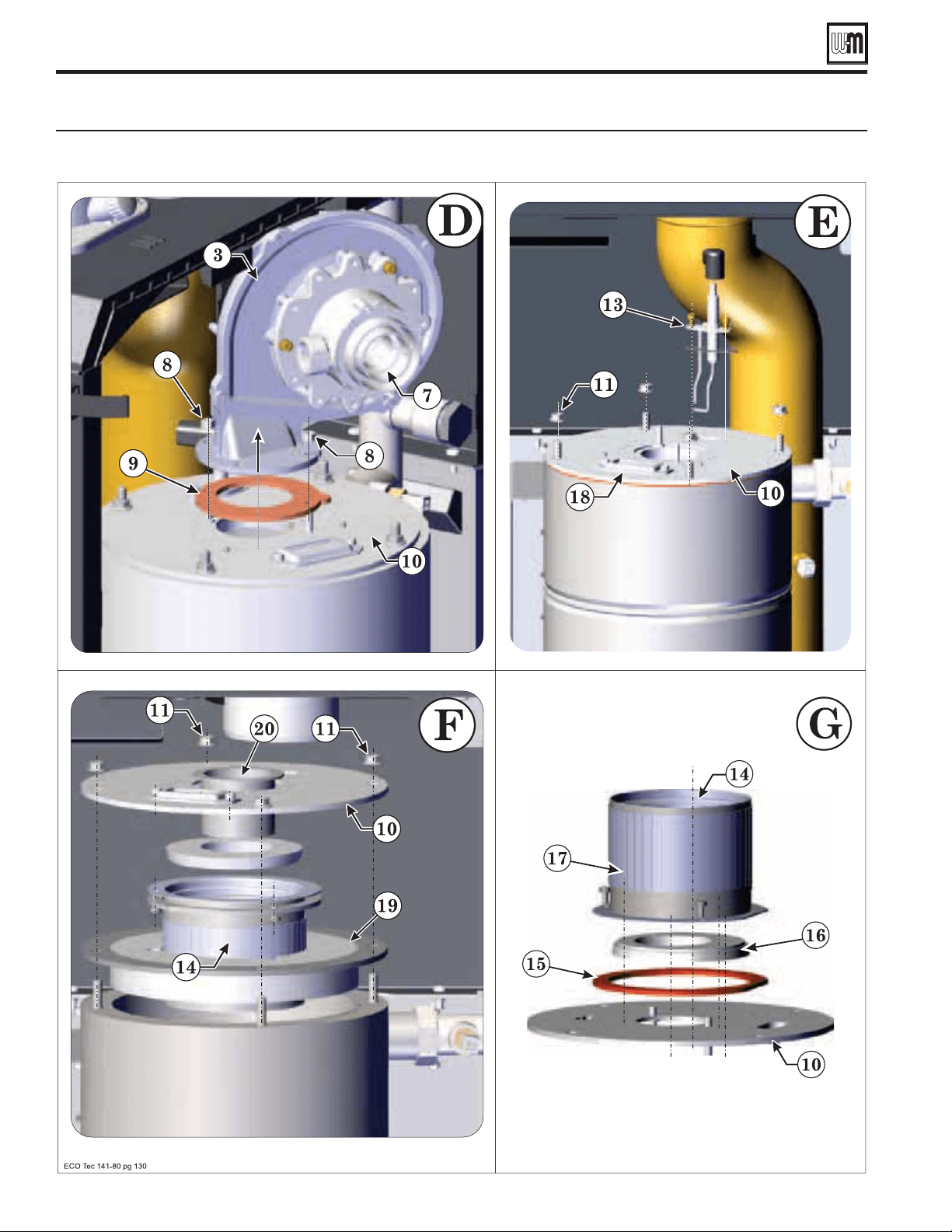
Part number 550-100-260/0520
130
ECO
®
Tec
GAS-FIRED WATER BOILER – 80/110/150/199 BOILER MANUAL
Cleaning heat exchanger fl ue side (continued)
Accessing the burner , heat exchanger, blower assembly and venturi removal. (See Legend, page 129 ).
Part number 550-100-260/0520
131
ECO
®
Tec
GAS-FIRED WATER BOILER – 80/110/150/199 BOILER MANUAL
Cleaning DHW and Brazed Plate Heat Exchanger
Procedure for chemical cleaning of
DHW circuit
Carefully read and follow the instructions contained.
Chemical cleaning and maintenance must be carried out by
professionally qualified personnel, in compliance with the current
regulations and according to the manufacturer’s instructions.
Do not carry out any operation on the sealed control parts.
Before carrying out any cleaning or maintenance operation,
disconnect the unit from the electrical power supply using the
switch and/or the special cut-off devices.
The disposal of chemicals and residues of chemical cleaning
should be carried out in an appropriate manner, in accordance
with current standards.
Domestic water for hot water production harder than 7 grains must
be treated before entering combi boiler to avoid scaling internal
combi boiler components.
Prolonged boiler operation with untreated water and/or hard
water will reduce the production of domestic hot water. Cleaning
the brazed plate and combi components may restore the
performance of hot water production. Use only NSF approved
chemicals that are safe for consumption and suitable for cleaning
the combi components - stainless steel 316 (brazed plate) and
brass (water manifolds and temperature sensor). Check chemical
manufacturer’s instructions and guidelines.
This procedure is intended as a guideline for restoration of the
functionality of domestic hot water production.
Boiler connections for cleaning domestic
water circuit
Hot Water Can Scald!
Consumer Product Safety Commission and some states
recommend domestic hot water temperature of 130°F
or less.
When installing an automatic mixing valve, selection
and installation must comply with valve manufacturer’s
recommendations and instructions.
Water heated to a temperature suitable for clothes
washing, dish washing and other sanitizing needs will
scald and cause injury.
Children, elderly, infirm, or physically handicapped
persons are more likely to be injured by hot water. Never
leave them unattended in or near a bathtub, shower or
sink. Never allow small children to use a hot water faucet
or draw their own bath. If anyone using hot water in
the building fits this description, or if state laws or local
codes require certain water temperatures at hot water
faucets, take special precautions:
Install automatic mixing valve set according to those
standards. (If used).
Use lowest practical temperature setting.
Check water temperature immediately after first heating
cycle and after any adjustment.
Studies have indicated that dangerous bacteria
can form in potable water distribution systems
if certain minimum water temperatures are not
maintained. Contact local health department for
more information.
These single wall heat exchangers comply with National
Standard Plumbing Code, provided that:
Boiler water (including additives) is practically non-
toxic, having a toxicity rating or class of 1, as listed in
Clinical Toxicology of Commercial Products.
Boiler water pressure is limited to max. 30 psig by
approved water relief valve.
Before you start, check the compatibility of
chemical cleaning product with the material
of the heat exchanger and its components.
The material of domestic hot water circuit is
stainless steel class AISI 316. The
brazed plate
and water manifolds and temperature sensor
are brass.
1 Boiler In
2 Domestic hot water outlet
3 Domestic cold water inlet
4 Boiler out
5 Gas inlet
6 Condensate tube
5
6
123
4
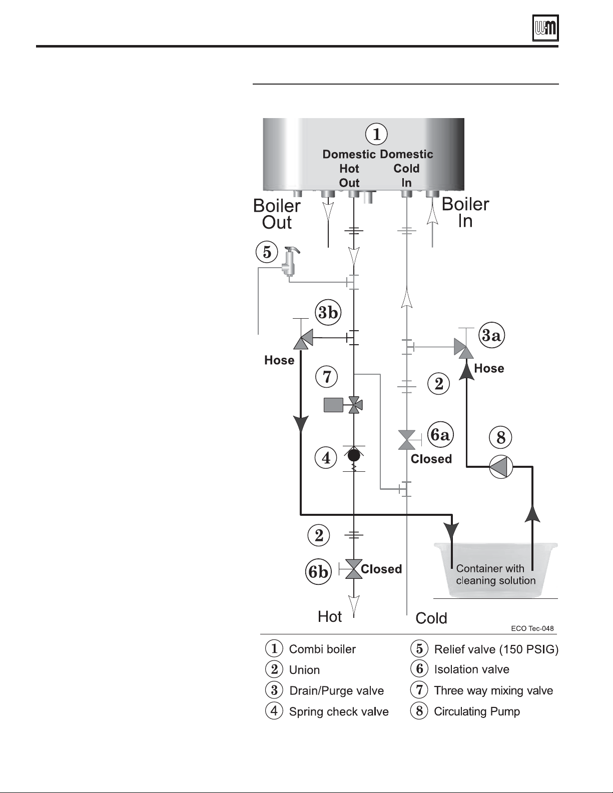
Part number 550-100-260/0520
132
ECO
®
Tec
GAS-FIRED WATER BOILER – 80/110/150/199 BOILER MANUAL
Cleaning DHW and Brazed Plate Heat Exchanger
Domestic water circuit cleaning diagram instructions
Actions for chemical cleaning
of Domestic hot water circuit
(Refer to Figure 117)
1. Shut down the boiler:
a. Follow “To Turn Off Gas to Appliance”
instructions on boiler and Operating
instructions.
b. Close the boiler manual gas valve.
2. Close off the of cold water inlet valve (Item
6a) placed before the boiler inlet.
3. Release residual pressure in domestic hot
water circuit in the boiler by opening a hot
water tap downstream of the boiler.
Then
close the DHW hot water outlet valve (Item
6b).
4. Connect the pipe fittings and hoses of the
pump for chemical cleaning to the cold water
inlet (3a) and domestic hot water outlet (3b).
5. Fill the pump tank with the de-scaling
chemical that is NSF approved. Be sure to
follow the manufacturer's instructions for
proper handling and disposable of the used
cleaning solution.
6. Circulate the fluid within the domestic hot
water circuit by activating the pump switch.
Reversing the cleaning flow through the
boiler’s domestic water circuit by placing
the circulating pump on the domestic hot
water outlet hose may be required for proper
cleaning.
7. At the end of the cleaning cycle, empty
the pump from chemical and recover the
product in appropriate containers for
disposal.
8. Fill the pump with water and perform
a washing cycle in order to remove the
chemical product still present within the
coils of the heat exchanger, recovering the
liquid in suitable containers for disposal.
9. Repeat the washing with water more than
once if necessary.
10. Disconnect the pipe fittings and hoses of
the pump for chemical cleaning from the
cold water inlet (3a) and domestic hot water
outlet (3b).
11. Open the cold water inlet valve placed before
the boiler inlet.
12. Reconnect the unit to the electrical power
supply using the switch and/or the special
cut-off devices and turn it ON.
13. Check the correct operation of the boiler
and production of domestic hot water.
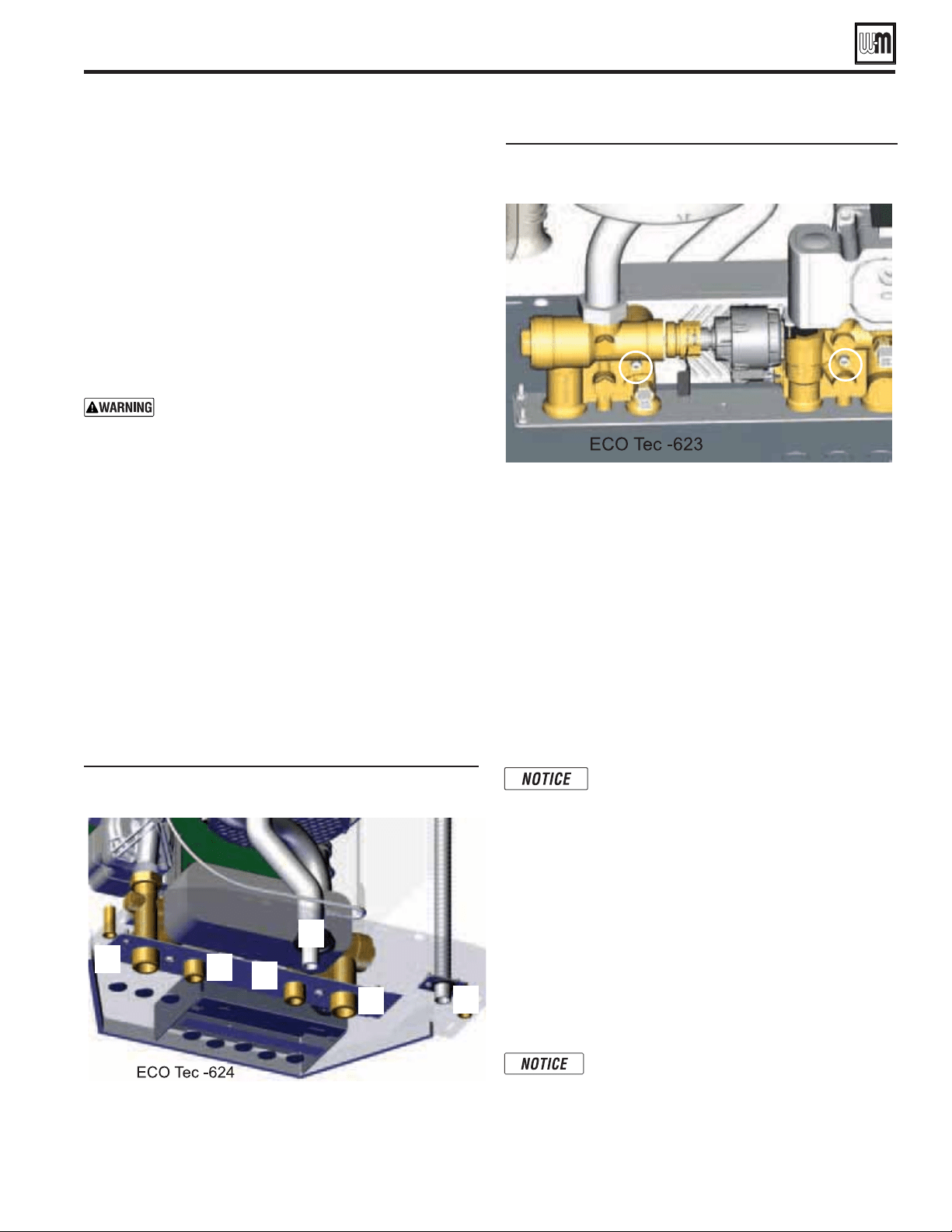
Part number 550-100-260/0520
133
ECO
®
Tec
GAS-FIRED WATER BOILER – 80/110/150/199 BOILER MANUAL
Before servicing Brazed Plate Heat
Exchanger Assembly
1. Cool down boiler and brazed plate heat exchanger assembly.
The following procedure may be used to cool down boiler
and components. First follow the operating instructions on
page 101 to properly shut off gas supply, but not the power to
the boiler. Turn on a domestic hot fixture and allow cool water
to flow through boiler. Boiler will lock out on an Ignition
Fault but the internal circulator should continue to run
cooling down the internal components. Once components
are cooled down, turn off all electrical power going to the
boiler following the operating instructions on page 101. If
procedure is followed, continue on to #3.
Wait until heat exchanger/boiler is cooled down
before proceeding. Water in brazed plate heat
exchanger may still be HOT!
Failure to do so can cause severe injury.
2. Shut down the boiler:
a. Follow “To Turn Off Gas to Appliance” instructions on
boiler and Operating instructions.
b. Close the boiler manual gas valve.
c. Only needed if cool down procedure in Step #1 was not
needed or followed.
3. Close the domestic cold water inlet isolation valve.
4. Release residual pressure in the domestic hot water circuit
in the boiler by opening a hot water tap downstream of the
boiler and drain the DHW components by opening the drain
valves.
5. Close the space heating valves Boiler Out (1) and Boiler In
(4) placed before the boiler connections.
6. Release residual pressure in boiler by operating relief valve
or opening boiler drain. Drain boiler by opening drain on
boiler in and boiler out.
Cleaning DHW and Brazed Plate Heat Exchanger
1 Boiler In
2 Domestic hot water outlet
3 Domestic cold water inlet
4 Boiler out
5 Gas inlet
6 Condensate tube
Removal of brazed plate heat exchanger
by loosening the two (2) screws.
Brazed plate heat exchanger removal for
cleaning
1. Remove the Brazed Plate Heat Exchanger from boiler
assembly by first removing the two (2) Allen Head bolts
with a 4mm Allen wrench, see Figure 119. Push brazed
plate back away from brazed plate manifolds clearing the
bolt bosses on the brazed plate from the manifolds. Then
slide the brazed plate up and to the left, removing it from
the boiler.
2. The treatment time must be chosen according to the
amount of scale deposits present in the brazed plate heat
exchanger. However, the amount of time must always be
less than the maximum treatment time specified by the
chemical manufacturer’s product data sheet.
The gas valve does NOT need to be removed
to replace brazed plate heat exchanger.
3. Brazed plate heat exchanger can be immersed in a chemical
cleaning bath.
4. At the end of the cleaning cycle recover the chemical product
in appropriate containers for disposal.
5. Flush the brazed plate with potable water in order to remove
the chemical product still present within the coils of the heat
exchanger, recovering the liquid in suitable containers for
disposal.
6. Repeat the rinsing with water more than once if necessary.
7. The cleaned brazed plate heat exchanger can now be
reinstalled.
e brazed plate heat exchanger must be
reinstalled in the same orientation.
Domestic water circuit on the Combi
(Back view shown)
4
3
2
1
6
5

Part number 550-100-260/0520
134
ECO
®
Tec
GAS-FIRED WATER BOILER – 80/110/150/199 BOILER MANUAL
Cleaning & Maintenance for Domestic Water
Inlet Manifold (Refer to Figure 121)
1. Follow “To turn off Gas Appliance” instructions on boiler and
Operating instructions and procedures 1-3 on page 133 "heat
exchanger and its serviceable components".
2. Remove the flow sensor electronic pickup attached, by carefully
lifting up and off of the flow transducer/turbine while keeping
the wire attached to the flow sensor electronic pickup.
3. Remove the flow transducer/turbine using an 18mm hexagonal
socket.
4. Detach the filter from the flow transducer/turbine, and clean
filter by using air or water to push through the inside of the filter,
opposite of normal flow. Be careful not to damage plastic filter.
5. Be sure to check the O-Ring and seat in the Inlet Manifold to
make sure that they are clean and in good condition. Replace
O-ring if damaged.
6. Reassemble flow transducer/turbine and filter, then reinsert flow
transducer/turbine into the block and tighten down to
8.9 lbs-ft
+/- 1.0 lbs-ft.
7. Re-connecting flow sensor electronic pickup to the flow
transducer/turbine by gently pushing it down on the flow
transducer/turbine. Make sure the wires are still connected to
the flow sensor electronic pickup.
8. When servicing the flow transducer/turbine and filter, it is
advised to inspect the by-pass filter.
9. Remove by-pass filter using 16mm (5/8”) wrench. Clean the
by-pass filter with water if needed.
Make sure by-pass is in good
working condition. Spring should be in relaxed state and in good
working order.
10. Re-insert by-pass and tighten down to 6.3 lbs-ft +/- 1.0 lbs-ft.
11. The boiler inlet water temperature sensor is located in this
manifold. Please refer to page 115 section “Checking temperature
sensors” to verify proper working condition
Cleaning/maintenance for Domestic Water Inlet & Outlet Manifolds
Brazed plate heat exchanger
reinstalled
Four (4) new gaskets must be placed in
the DHW inlet and DHW return plate
connections to seal brazed plate heat
exchanger. See Figure 132, page 144 for service
part numbers.
1. Slide the brazed plate heat exchanger into rear of enclosure
(ensure brazed plate is in proper orientation; label stating
“This side up” should be facing up)
2. Lift brazed plate heat exchanger slightly up and align
with DHW connections, reinstall the two (2) Allen head
screws, and tighten securely. (Torque to 31 lb-in. +/- 4
lb-in.).
When re-installing components, make sure
gaskets are in good condition and properly
aligned before tightening screws.
3. Open the valve of CH system supply (1) and return (5)
and fill the boiler with water. Purge all air from system.
Check all water joints and ensure no leaks are present.
4. Open valves of the domestic cold water inlet and the
domestic hot water outlet. Flush water through system
by opening a fixture. Check all water joints and ensure
no leaks are present.
5. Follow the operating instructions on page 101 to turn
on the gas supply and to restore the electrical power to
the boiler. The 3-way valve may be toggled back and
forth to bleed air from the system. Follow procedure
1 through 3 on page 112 under “3 way valve test”. B e
sure to reset and clear any faults that may have occurred
during this service.
Reinstallation of brazed plate gaskets
to brazed plate heat exchanger
Domestic Water Inlet Manifold components
Flow sensor
electronic
pickup
Flow transducer
/turbine
Bypass
and
Inlet
Manifold
T
H
I
S
S
I
D
E
U
P
ECO Tec -620
Gaskets
Gaskets
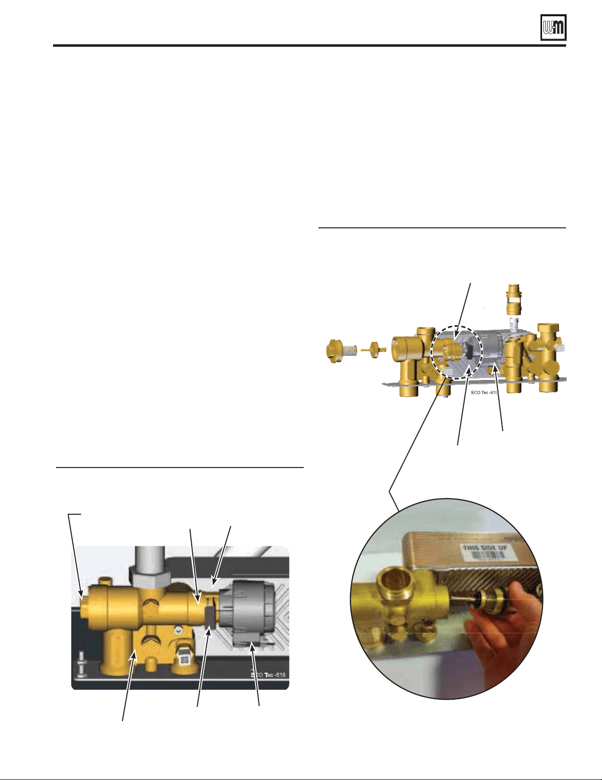
Part number 550-100-260/0520
135
ECO
®
Tec
GAS-FIRED WATER BOILER – 80/110/150/199 BOILER MANUAL
Cleaning/maintenance for Domestic Water Inlet & Outlet Manifolds
12. Open valves of the domestic cold water inlet and the domestic
hot water outlet. Flush water through system by opening a
fixture. Check all water joints and ensure no leaks are present.
Cleaning and maintenance for Domestic
Water Outlet Manifold (Refer to Figure 122
and Figure 123)
1. Follow “To turn off Gas Appliance” instructions on boiler and
Operating instructions and procedures 4 and 5 on page 133
2. Slide actuator retaining clip out of the slot, see Figure 122.
3. Remove the actuator from Domestic Water Outlet Manifold
while keeping wire attached.
4. Remove spacer using 28mm (1 1/8”) wrench, removing the
sanitary shutter with it.
5. Remove heating cartridge using 22mm (7/8”) wrench
6. Clean components for both the Heating Cartridge and the
Sanitary Shutter. Ensure springs are working properly by
compressing them and shut off valves and valve seats are in
good condition. If components are damage or have excessive
wear they must be replaced.
7. Check both O-rings and seats to make sure they are
undamaged. Replace O-rings if necessary. Clean O-ring
seats and then apply a small amount of non-petroleum
grease afterwards.
8. Apply a small amount of non-petroleum grease to the tip
of the rod of the sanitary shutter, and reassemble it with the
spacer.
9. Reinstall shutter/spacer into the Domestic Water Outlet
Manifold, but do not tighten part.
Domestic Water Outlet Manifold
components
10. Screw heating cartridge back into the Domestic Water Outlet
Manifold, and tighten it down to 8.9 lbs-ft +/- 1.0 lbs-ft.
11. Tighten spacer down to
8.9 lbs-ft +/- 1.0 lbs-ft.
12. Reinstall actuator and actuator retaining clip back onto the
Domestic Water Outlet Manifold.
13. The Domestic Hot Water temperature sensor is located in
this manifold. Please refer to page 115 section “Checking
temperature sensors” to verify proper working condition
14. Open the valves of CH system supply and return and fill the
boiler with water. Purge all air from system. Check all water
joints and ensure no leaks are present.
Domestic Water Outlet Manifold
components disassembled
Heating
Cartridge
Spacer
Outlet Manifold
Actuator
Sanitary shutter
(Not pictured)
Actuator
Clip
Actuator
Clip
Actuator
Spacer
Part number 550-100-260/0520
136
ECO
®
Tec
GAS-FIRED WATER BOILER – 80/110/150/199 BOILER MANUAL
Propane conversion kits and instructions
DO NOT SERVICE THE
BOILER WITHOUT A
MAINTENANCE KIT
AVAILABLE
The maintenance kit includes components that may
have to be replaced when accessing or disassembling
parts of the boiler. Failure to replace damaged
components and to use only the parts specifically
intended for the boiler can result in severe personal
injury, death or substantial property damage. See
Figure 125, page 137 for part number.
OBTAIN PARTS ONLY THROUGH
WEIL-McLAIN
Replacement parts must be purchased through a local Weil-
McLain distributor. When ordering, specify boiler model and size
and include description and part number of replacement part.
Results from using modified or other manufactured parts will
not be covered by warranty and may damage boiler or impair
operation.
THE BOILER CONTAINS CERAMIC
FIBER MATERIALS
. Use care when
handling these materials per instructions on page 106 of this
manual. Failure to comply could result in severe personal injury.
REINSTALL Jacket door
Inspect boiler jacket door gaskets on front of cabinet and reinstall
boiler jacket door after start or servicing. The boiler jacket door
must be securely fastened to the boiler to prevent boiler from
drawing air from inside the boiler room. This is particularly
important if the boiler is located in the same room as other
appliances. Failure to keep the jacket door securely fastened could
result in severe personal injury or death.
BEFORE SERVICING or MAKING
CONNECTIONS —
LABEL WIRES BEFORE REMOVING
Label all wires prior to disconnection when
servicing controls. Wiring errors can cause
improper and dangerous operation.
REPLACEMENT PART
NUMBERS
Weil-McLain Boilers and
Controls Repair Parts Lists
.
WHEN OPERATING THE
BOILER ON PROPANE GAS
ECO
Tec
.
80/110
510-811-415
See
page 14.
150
510-811-416
See
page 14.
199
510-811-417
See
page 14.
Replacement parts
Miscellaneous service parts and kits
Part number 550-100-260/0520
137
ECO
®
Tec
GAS-FIRED WATER BOILER – 80/110/150/199 BOILER MANUAL
Description
Part Number
CHEMICALS
Antifreeze, Sentinel X500, 1 Gallon . . . . . .
Corrosion inhibitor, Sentinel X100 . . . . . . .
Sentinel X100 Quick Test Kit. . . . . . . . . .
592-900-029
592-900-002
592-900-005
ECO
Tec 80/110 maintenance kit — igniter,
igniter gasket, venturi gasket, cover plate gasket,
venturi-gas valve o-ring, refractory, inhibitor test
kit, clips and instructions
383-700-265
ECO
Tec 155 maintenance kit — igniter, igniter
gasket, venturi gasket, cover plate gasket, venturi-
gas valve o-ring, refractory, inhibitor test kit, clips
and instructions
383-700-266
ECO
Tec 199 maintenance kit — igniter, igniter
gasket, venturi gasket, cover plate gasket, venturi-
gas valve o-ring, refractory, inhibitor test kit, clips
and instructions
383-700-267
Condensate trap kit (supplied with boiler) —
condensate tube, barb polypropylene 3/16, and hose
clamps
383-700-268
ECO
Tec
383-700-339
Wall bracket
383-700-386
ECO
Tec Easy Up Manifold
383-700-343
511-100-005
DHW Service Valve
383-700-346
System sensor (2)
383-700-371
Condensate neutralizer kit 383-500-631
available from Weil-McLain
Weil-McLain Direct Exhaust Venting Kit
Includes interior/exterior intake/exhaust plates.
2" & 3" vent screens, templates and mounting
hardware
383-500-778
Weil-McLain sidewall vent/air cap termination kit
for PVC vent and air pipes
Includes sidewall vent/air termination cap, inside
and outside cover plates, and mounting hardware;
installed 3 x 2 adapter if using 2" vent/air pipes)
383-500-397
Weil-McLain sidewall vent/air cap termination kit
for AL29-4C vent pipe and PVC air pipe
Includes sidewall vent/air termination cap, inside
and outside cover plates, and mounting hardware;
openings are sized for 3" SS vent pipe and 3" PVC
using 2" vent/air pipes)
382-200-430
Description
Part Number
Bird screens (1 screen each)
For 2" PVC vent and air pipes . . . . . . . . .
For 3" PVC vent and air pipes . . . . . . . . .
560-907-728
383-500-105
Sidewall separate pipes vent/air termination kits
(includes two cover plates)
Kit for 2" PVC vent and air pipes. . . . . . . .
Approved for 80/110/150 models only
Kit for 3" PVC vent and air pipes. . . . . . . .
Kit for 3" AL29-4C SS vent pipe and PVC air pipe
383-700-171
383-500-100
383-700-172
PVC concentric vent kit — horizontal or vertical
(includes components for concentric assembly)
Kit for 2" PVC vent and air pipes. . . . . . . .
Approved for 80/110/150 models only
Kit for 3" PVC vent and air pipes. . . . . . . .
383-700-167
383-500-350
PVC concentric vent kit — horizontal or vertical
(includes components for concentric assembly)
2" PVC concentric . . . . . . . . . . . . .
Approved for 80/110/150 models only
3" PVC concentric . . . . . . . . . . . . .
196005
196006
M&G Simpson-Duravent PolyPro VERTICAL
concentric vent/air kit; color = black (part number
shown) or terra cotta (add -TC suffix)
2" polypropylene pipe . . . . . . . . . . . .
3" polypropylene pipe . . . . . . . . . . . .
2PPS-VK
3PPS-VK
M&G Simpson-Duravent PolyPro SIDEWALL
separate air and vent pipes
2" polypropylene pipe . . . . . . . . . . . .
3" polypropylene pipe . . . . . . . . . . . .
2PPS-HTP
3PPS-HTP
M&G Simpson-Duravent PolyPro
3" to 2" Adapter Polypropylene . . . . . .
3PPS-R2L
Centrotherm INNOFLUE SIDEWALL
concentric vent/air kit
3" polypropylene pipe . . . . . . . . . . . .
2" polypropylene pipe. . . . . . . . . . . .
ICWT352
ICWT242
Centrotherm INNOFLUE VERTICAL
concentric vent/air kit
2" polypropylene pipe . . . . . . . . . . . .
3" polypropylene pipe . . . . . . . . . . . .
ICRT2439
ICRT3539
Centrotherm INNOFLUE
3" to 2" Adapter Polypropylene . . . . . . .
ISRD0302
Stainless Steel Vent/Flue & AIr Adapter Connections
Heat Fab, Inc. – Saf T Vent
Z Flex, Inc. – Z Vent
Metal Fab, Inc. – CORR/Guard
9301PVC
2SVSAFNS03
3CGPVA
Replacement parts (continued)
Replacement parts (continued)
Jacket parts — ECO
Tec 80/110/150/199 (see Figure 127, page 139 for illustration)
Part number 550-100-260/0520
138
ECO
®
Tec
GAS-FIRED WATER BOILER – 80/110/150/199 BOILER MANUAL
Item Name Description / contents Part Number
100
Jacket door Jacket door, gaskets and labels
383-700-269
110
Gasket bottom, top & sides for jacket door Seals for door bottom, sides and top of cabinet
383-700-363
120
Jacket Assembly Jacket panels, gaskets and hardware
383-700-271
130
Flue pipe 80mm Polypropylene Offset flue pipe
383-700-273
140
Adapter Vent-Air Inlet Top air inlet adapter with internal gasket
383-700-274
150
Adapter Vent-Air Outlet Top air outlet adapter with internal gasket
383-700-275
160
Air baffle and screws Air baffle and screws
383-700-276
170
Display/bracket gasket Display gasket
383-700-361
Display/door gasket Display housing to door gasket
180
Panel control bracket/cover Control bracket, cover and hardware
383-700-280
190
Display board bracket and gaskets (Not
shown)
Mounting for the display to inside of cabinet
383-700-281
200
Wall mount bracket
383-700-386
210
Dome plug Hole plug, 1-3/8" Dia. Black, for sealing Combi pipe holes
383-700-362
Pipe grommet seal (for 2" I.D. hole) Seals top water pipe to cabinet
Pipe grommet seal (for 1-5/8
"
I.D. hole) Seals condensate tube to bottom of cabinet
220
Flue gasket
383-700-384
230
Kit-Service Cabinet Top
383-700-390
240
Kit-Service Cabinet Door Top
383-700-391
250
Water pipe bracket
383-700-393
Replacement parts (continued)
Jacket assembly — ECO
Tec 80/110/150/199 (see Figure 126, page 138 for part numbers)
Part number 550-100-260/0520
139
ECO
®
Tec
GAS-FIRED WATER BOILER – 80/110/150/199 BOILER MANUAL
Part number 550-100-260/0520
140
ECO
®
Tec
GAS-FIRED WATER BOILER – 80/110/150/199 BOILER MANUAL
Item Name Part Number
Model
80
Model
110
Model
150
Model
199
100
Heat exchanger
383-700-284
——
383-700-285 — —
—
383-700-286 — — —
110
Heat exchanger, condensate dish, cover plate, burner, igniter, sight glass,
refractory, water sensors, gaskets, silicone, and hardware
(includes Items 100, 120, 130, 140, 150,160,170,180, 210, 220, and 230)
383-700-287
——
383-700-288 — —
—
383-700-289 — — —
120
Insulation with integrated seal - bottom cover plate
383-700-291
——
383-700-292 — —
—
383-700-293 — — —
130
Burner
383-700-297
——
383-700-298 — —
—
383-700-299 — — —
140
Disc burner refractory
383-700-372
——
383-700-373 — —
150
Burner gasket
383-700-300
——
383-700-301 — —
160
Burner tube
383-700-290
—
170
Ignition electrode kit (igniter, gasket and screws)
383-700-295
180
Kit - Service Silencer O-ring, blower gasket, gas flex line, and igniter gaskets
383-700-360
190
Sight glass kit ( bracket, glass, gaskets, and hardware)
383-700-185
200
Condensate dish
383-700-331
——
383-700-332 — —
—
383-700-333 — — —
210
Condensate dish gasket
383-700-381
——
383-700-382 — —
—
383-700-383 — — —
220
Flue gasket
383-700-384
230
Flue restrictor
383-700-364
——
240
Top cover insulation & heat exchanger insulation wrap
383-700-366
——
383-700-367 — —
—
383-700-368 — — —
Replacement parts (continued)
Heat exchanger parts ECO
Tec 80/110/150/199 (see Figure 129, page 141 for illustration)
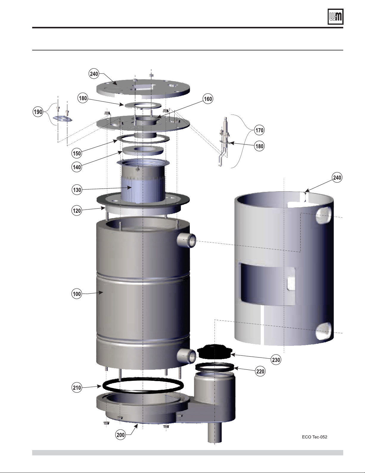
Part number 550-100-260/0520
141
ECO
®
Tec
GAS-FIRED WATER BOILER – 80/110/150/199 BOILER MANUAL
Replacement parts (continued)
Heat exchanger assembly ECO
Tec 80/110/150/199 (see Figure 128, page 140 for part numbers)
Part number 550-100-260/0520
142
ECO
®
Tec
GAS-FIRED WATER BOILER – 80/110/150/199 BOILER MANUAL
Item Name Part Number
Model
80/110
Model
150
Model
199
100
Air silencer, clip and gasket
383-700-294
110
Kit - Service Silencer O-ring, blower gasket, gas flex line, and igniter gaskets
383-700-360
120
Blower, gasket and hardware
383-700-303
—
383-700-304 — —
130
Venturi
383-700-305
——
383-700-306 —
—
383-700-307 — —
140
Air silencer clip
383-700-308
150
Gas valve assembly
383-700-313
160
Adapter gas flex line, elbow, gas valve flange with hardware and the gas pipe
383-700-283
170
Gas flex line
383-700-224
Replacement parts (continued)
Combustion components parts ECO
Tec 80/110/150/199 (see Figure 131, page 143 for illustration)
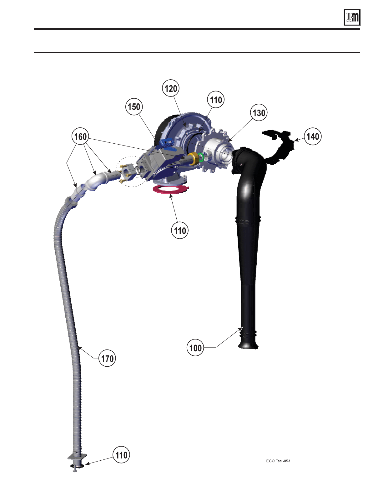
Part number 550-100-260/0520
143
ECO
®
Tec
GAS-FIRED WATER BOILER – 80/110/150/199 BOILER MANUAL
Replacement parts (continued)
Combustion components parts ECO
Tec 80/110/150/199 (see Figure 130, page 142 for part numbers)
Part number 550-100-260/0520
144
ECO
®
Tec
GAS-FIRED WATER BOILER – 80/110/150/199 BOILER MANUAL
Item Name Description / contents Part Number
100
Grommet - water pipe sealing
383-700-361
110
Pipe - water top
383-700-377
120
Condensate drain tube with hose nipple
383-700-268
130
Pipe - water flex 1"
383-700-378
140
Pipe - water return
383-700-375
150
Brazed plate heat exchange includes Item 230
383-700-355
160
DHW flow manifold includes Item 210
383-700-356
170
Actuator - 3-way valve includes retaining clip
383-700-358
180
DHW return manifold with sensor tapping, includes Item 220
383-700-357
190
Circulator
383-700-379
200
Flow transducer/turbine
383-700-380
210
DHW flow manifold components
383-700-349
220
DHW return manifold components
383-700-350
230
Brazed plate gaskets (not shown)
383-700-359
240
DHW, return & supply gaskets
383-700-392
250
Pressure switch
383-700-329
260
Water temperature sensor
383-700-319
270
Flow sensor electronic pickup
383-700-389
Replacement parts (continued)
Combi water piping for ECO
Tec 80/110/150/199 (see Figure 134, page 145 for illustration)
Heating Only water piping for ECO
Tec 80/110/150/199 (see Figure 134, page 145 for illustration)
Item Name Description / contents Part Number
100
Grommet - water pipe sealing
383-700-361
110
Pipe - water top
383-700-377
120
Condensate drain tube with hose nipple
383-700-268
240
DHW, return & supply gaskets
383-700-392
250
Pressure switch
383-600-073
260
Water temperature sensor
383-700-319
280
Pipe - water flex 1"
383-700-378
290
Pipe - water return
383-700-375
300
Pipe - water return bottom with sensor tapping
383-700-376
310
Pipe - water supply bottom
383-700-374
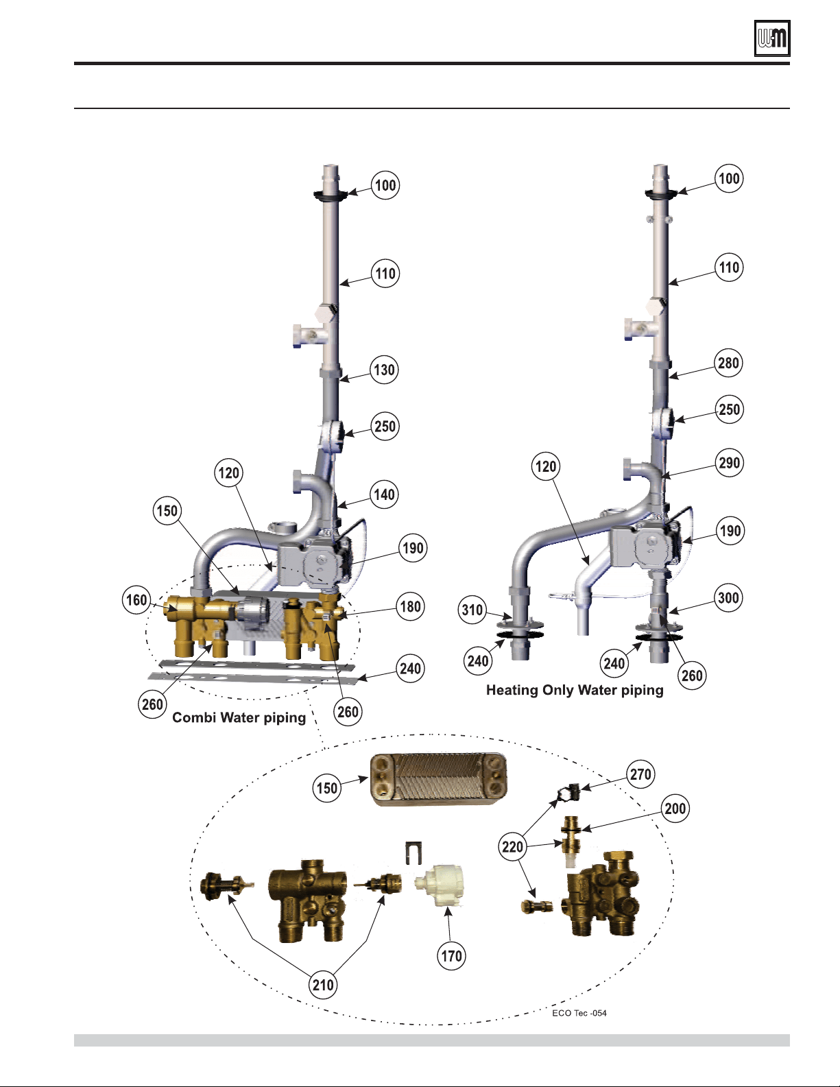
Part number 550-100-260/0520
145
ECO
®
Tec
GAS-FIRED WATER BOILER – 80/110/150/199 BOILER MANUAL
Replacement parts (continued)
Combi and Heating Only water piping for ECO
Tec 80/110/150/199
(see Figure 132, page 144 or Figure 133, page 144 for part numbers)
Controls and electrical components - ECO
Tec 80/110/150/199 (see Figure 136, page 147 for illustration)
Part number 550-100-260/0520
146
ECO
®
Tec
GAS-FIRED WATER BOILER – 80/110/150/199 BOILER MANUAL
Item Name Description / contents Part Number
100
Flue temperature sensor & grommet One (1) sensor & grommet
383-500-600
110
Outdoor temperature sensor
383-500-125
120
System temperature sensor Two (2) sensors
383-700-371
130
Transformer 120V/50V/24V 50 VA transformer
383-700-320
140
Display board assembly Includes circuit board and plastic housing
383-700-321
150
Control module assembly Control module and housing
383-700-322
160
Wire harness — line voltage (not shown)
383-700-323
170
Wire harness — low voltage (not shown)
383-700-324
180
Ignition cable (not shown)
383-500-619
190
Fuse 2.5 amp, (qty. 5) fast blow Ato 4 amp, fast blow
Fuse 3 amp, (qty. 1) fast blow Ato 4 amp, fast blow
Fuse 4 amp, (qty. 1) fast blow Ato 4 amp, fast blow
(not shown — see Figure 102, page 115)
383-700-369
200
Jumper for low voltage terminal blocks (not shown) Five (5) Jumpers
383-500-641
210
Connector electrical control (not shown) Includes Eight (8) connectors
383-900-111
220
Low voltage sealed wire grommet (not shown) Seals thermostat wire at entrance to cabinet
383-700-385
230
Harness - Blower jumper (not shown)
383-700-351
240
Harness - Display to control module (not shown)
383-700-352
250
Harness - Actuator (Combi only) (not shown)
383-700-353
260
Harness - Flow sensor (Combi only) (not shown)
383-700-354
270
Harness - BMS (not shown)
383-700-272
280
Relief valve
30 PSIG relief valve — shipped loose for field
installation
383-500-095
290
Pressure & temperature gauge Shipped loose for field installation
380-000-000
Replacement parts (continued)
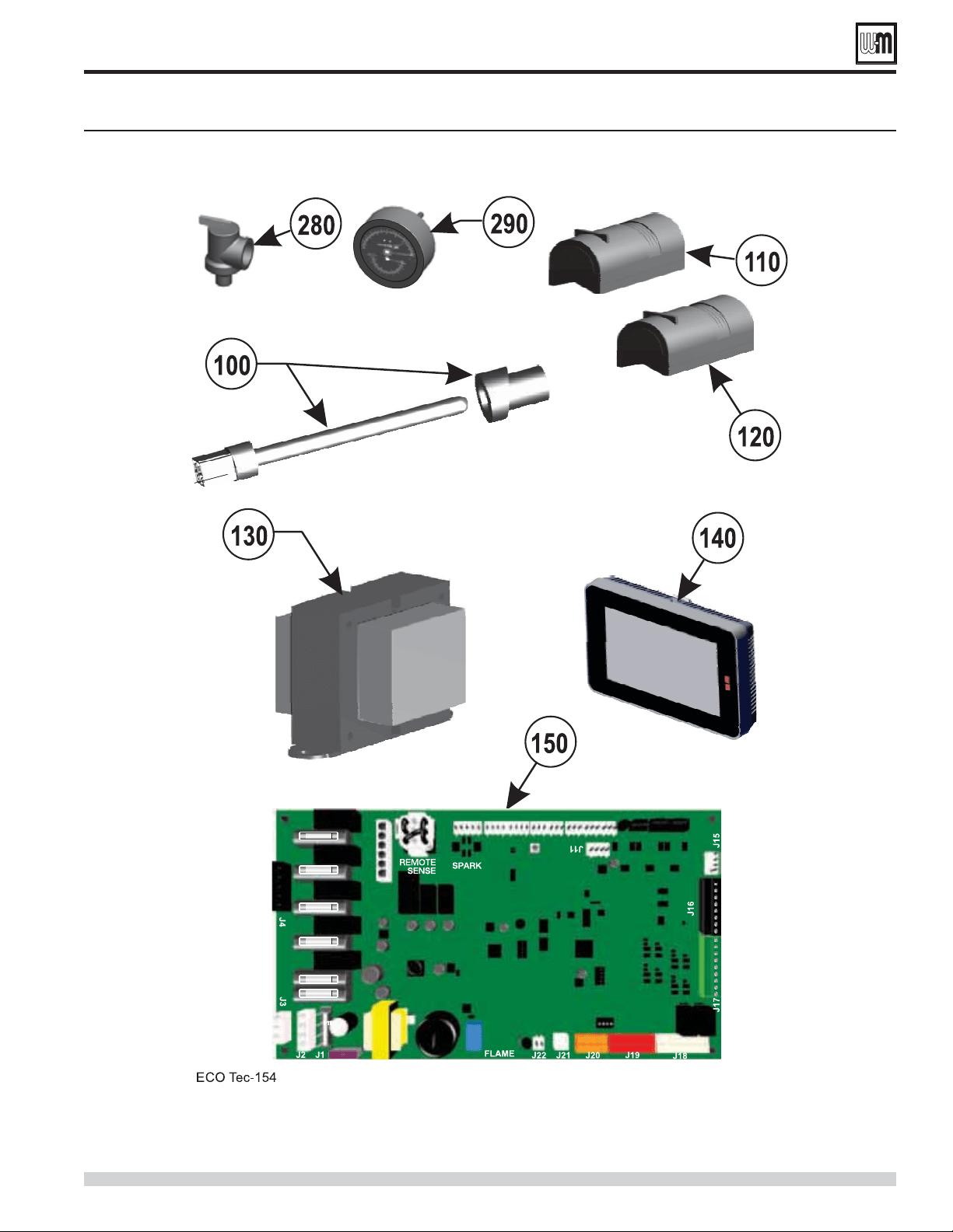
Part number 550-100-260/0520
147
ECO
®
Tec
GAS-FIRED WATER BOILER – 80/110/150/199 BOILER MANUAL
Replacement parts (continued)
Controls and electrical assemblies - ECO
Tec 80/110 /150/199 (see Figure 135, page 146 for part numbers)
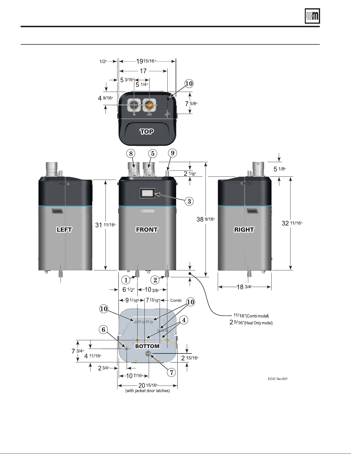
Part number 550-100-260/0520
148
ECO
®
Tec
GAS-FIRED WATER BOILER – 80/110/150/199 BOILER MANUAL
Dimensional data —
ECO
Tec
80/110/150/199 (all dimensions in inches)
Dimensions
Boiler Out tapping — 1" Male NPT Gas connection 1/2" Male NPT
Boiler In tapping — 1" Male NPT Condensate tube connection
Control display and navigation buttons Air connection: 3" PVC/PP/SS
DHW In/Out tapping — 3/4" Male NPT Boiler tapping for relief valve - 3/4" Male NPT
Vent connection: 3" PVC/PP/SS Electrical entrance openings

Part number 550-100-260/0520
149
ECO
®
Tec
GAS-FIRED WATER BOILER – 80/110/150/199 BOILER MANUAL
Ratings —
ECO Tec boilers
Ratings and engineering data —
ECO
Tec
80/110/150/199
Notes
As an Energy Star Partner, Weil-McLain
has determined that ECO
Tec 80, 110,
150 and 199 boilers meet the Energy Star
guidelines for energy efficiency.
NOTE: Adjusting boiler firing rate will
affect AFUE rating.
Based on standard test procedures
prescribed by the United States
Department of Energy. Ratings also
referred to as CSA Output.
NOTE that only DOE Heating Capacity
and AFUE are certified by AHRI. AFUE
is also know as Annual Fuel Utilization
Efficiency or Seasonal Efficiency.
Net AHRI ratings are based on net
installed radiation of sufficient quantity
for the requirements of the building
and nothing need be added for normal
piping and pickup. Ratings are based on a
piping and pickup allowance of 1.15. An
additional allowance should be made for
unusual piping and pickup loads.
ECO
Tec boilers must be direct-vented.
ECO
Tec boilers require special venting,
consistent with Category IV boiler.
Use only the vent materials and methods
specified in this manual.
ECO
Tec boilers may be direct exhaust
vented with Kit option.
ECO
Tec vent/air pipes can be either
2" or 3". An adapter is required for 2"
venting.
All vent and air pipe elbows must be sweep
elbows, NOT short-radius elbows.
Ratings shown are for sea level applications
only. For altitudes from sea level to 2,000 feet
above sea level, the ECO
Tec boiler requires no
modifications and automatically derates itself
by approximately 4% per 1000 feet above sea
level.
All of the boilers will automatically de-rate
as vent/air pipe length increases, due to the
pressure loss through the piping. For vent/air
pipe lengths less than the maximum, the derate
equals the value above (% Input derate vs. vent
length) times vent length ÷ 100, for all except
for the 199 - 2" venting. 199 -2" derate equals
13% times vent length ÷ 50.
OUTDOOR SENSOR
IMPORTANT
In accordance with
, this boiler is equipped
with a feature that saves energy by
reducing the boiler water temperature as
the heating load decreases. This feature
is equipped with an override which is
provided primarily to permit the use of
an external energy management system
that serves the same function.
An external energy management system is installed that reduces the boiler water
temperature as the heating load decreases.
This boiler is not used for any space heating.
This boiler is part of a modular or multiple boiler system having a total input of 300,000
BTU/hr or greater.
This boiler is equipped with a tankless coil (not applicable to Combi model).
Boiler
Model
ECO
Tec
CSA
Input
Heating
Capacity
Seasonal
Net
Water
Boiler
Water
Content
Vent/
Comb. Air
Connection
Diameter
% Input derate vs vent length
(Values shown are at MAX
vent/air pipe length —
See Note 6)
Btuh
(Note 5)
Btuh
(Note 2)
AFUE, %
(Note 1)
MBH
(Note 3) Gallons
Inches
(Note 4)
Natural gas Propane
2"
Vent/air
piping
3"
Vent/air
piping
2"
Vent/air
piping
3"
Vent/air
piping
80 80,000 74,000 95.0 64
2.2 3" PVC/PP/SS 5 % –– 5 % ––
110 110,000 100,000 95.0 87
2.2 3" PVC/PP/SS 10% 5 % 10% 5 %
150 150,000 139,000 95.0 121
3.1 3" PVC/PP/SS 13% 5 % 13% 5 %
199 199,000 184,000 95.0 160
3.8 3" PVC/PP/SS 13% 5 % 13% 5 %
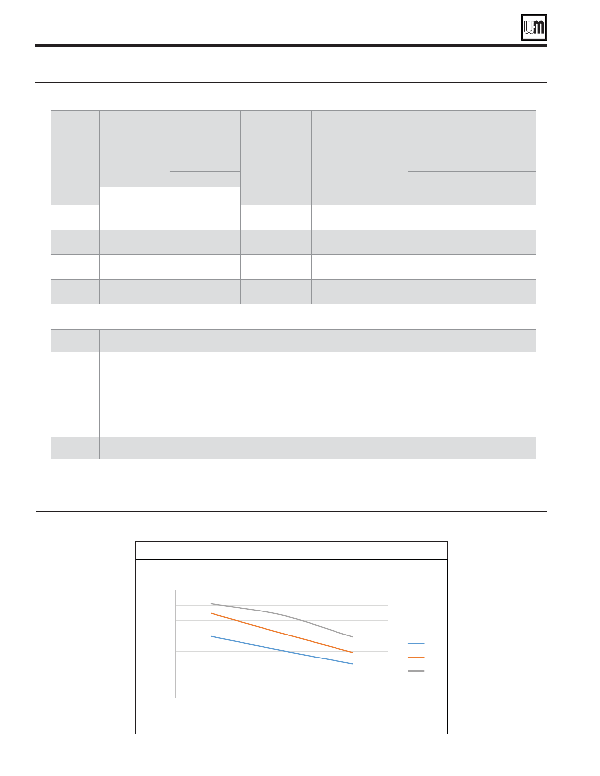
Part number 550-100-260/0520
150
ECO
®
Tec
GAS-FIRED WATER BOILER – 80/110/150/199 BOILER MANUAL
Boiler
Model
Shipping
weight
Operating
weight
Water
content
per boiler
(Provide a
separate vent for
each boiler)
Pounds
per boiler
Pounds
per boiler
Gallons
per boiler
GPM
@ 20°F
rise
GPM
@ 40°F
rise
Amps
per boiler
Note 1
Note 2 Note 3
HO / Combi HO / Combi
80
138 / 147 141 / 152 2.2 7.4 3.7 2" or 3" 15.0
110
138 / 147 141 / 152 2.2 10.0 5.0 2" or 3" 15.0
150
150 / 159 162 / 172 3.1 13.9 7.0 2" or 3" 15.0
199
161 / 170 178 / 187 3.8 18.4 9.2 2" or 3" 15.0
1
Operating weight is the total weight of the boiler, including water.
2
Vent/air pipes can be either 2" or 3" pipe.
All of the boilers will automatically de-rate as vent/air pipe length increases, due to the pressure loss through the piping.
See Figure 138, page 149 for details.
All
ECO
Tec installations require a separate vent pipe and termination for each boiler.
. Install and terminate vents as described in vent/air installation instructions in this manual.
Combustion air piping can be individually piped or manifolded.
3
Total amp requirement includes up to four (4) circulators, not exceeding 2.2 amps per circulator.
Ratings—
ECO Tec boilers
Engineering Data — ECO
Tec 80/110/150/199 boilers
DHW Temperature Rise vs Flow (Chart 3)
Chart 3
0.0
1.0
2.0
3.0
4.0
5.0
6.0
7.0
40 50 60 70 80 90 100
DHW Flow Rate (gpm)
DHW Delta (°F)
DHW Temperature Rise vs. Flow
110
150
199

Part number 550-100-260/0520
151
ECO
®
Tec
GAS-FIRED WATER BOILER – 80/110/150/199 BOILER MANUAL
ECO
Tec
: ❏ Installation instructions have been followed.
❏ Check-out sequence has been performed.
❏ Information on next two pages is certified to be correct.
❏ Information received and left with owner/maintenance person.
Installer
(Company) (Address) (Phone) (Installer’s Signature)
Installation and Service Certificate
Part number 550-100-260/0520
152
ECO
®
Tec
GAS-FIRED WATER BOILER – 80/110/150/199 BOILER MANUAL
Installation and Gas Boiler Data Collection Sheet
ECO
Tec __________ / Series _______
ECO
Tec ______ ___________
Sensor:
___________
___________
___________ V
___________ V
___________ Sec
___________ Sec
___________%
___________%
Part number 550-100-260/0520
153
ECO
®
Tec
GAS-FIRED WATER BOILER – 80/110/150/199 BOILER MANUAL
Installation and Gas Boiler Data Collection Sheet
___________ ___________
___________ ___________
___________ ___________
___________ V ___________ V
___________ V ___________ V
___________Sec ___________Sec
___________Sec ___________Sec
___________% ___________%
___________% ___________%
Part number 550-100-260/0520
154
ECO
®
Tec
GAS-FIRED WATER BOILER – 80/110/150/199 BOILER MANUAL
Contact: Name:
Contractor: Phone:
Job name: Model:
City, state: CP#:
Distributor: Installed:
Near boiler pipe size:
DHW tank (yes/no):
DHW direct/system:
DHW model:
DHW pipe size:
DHW circulator model:
Is there air in system?:
Ignition retries:
Manual reset CNT:
Auto reset CNT:
Display:
Main micro:
Second micro:
ECO Tec Gas Boiler Data Collection Sheet
Fault Name: Output 1: Fault Name: Output 1:
Fault Type: Output 2: Fault Type: Output 2:
Fault Time: Output 3: Fault Time: Output 3:
Fault Date: Output 4: Fault Date: Output 4:
Status: Boiler Circ: Status: Boiler Circ:
Blower signal:
Blower signal:
Status:
Additional Heat
Demand:
Status:
Additional Heat
Demand:
Boiler out 1: Alarm: Boiler out 1: Alarm:
Boiler out 2: Boiler out 2:
DHW out 1: DHW out 1:
DHW out 2: DHW out 2:
Boiler in: Boiler in:
Flue 1: Flue 1:
Flue 2: Flue 2:
Outdoor: Outdoor:
Status: Status:
Input 1: Input 1:
Input 2: Input 2:
Input 3: Input 3:
Input 4: Input 4:
Manual limit: Manual limit:
Auto limit: Auto limit:
Low WTR Cutoff: Low WTR Cutoff:
Air Pressure Switch: Air Pressure Switch:
Closure Switch: Closure Switch:
Blower
Speed: Blower Speed:
Flame signal: Flame signal:
DHW Flow: DHW Flow:
Status: Status:
Gas valve: Gas valve:

Part number 550-100-260/0520
155
ECO
®
Tec
GAS-FIRED WATER BOILER – 80/110/150/199 BOILER MANUAL
Fault Name: Output 1: Fault Name: Output 1:
Fault Type: Output 2: Fault Type: Output 2:
Fault Time: Output 3: Fault Time: Output 3:
Fault Date: Output 4: Fault Date: Output 4:
Status: Boiler Circ: Status: Boiler Circ:
Blower signal:
Blower signal:
Status:
Additional Heat
Demand:
Status:
Additional Heat
Demand:
Boiler out 1: Alarm: Boiler out 1: Alarm:
Boiler out 2: Boiler out 2:
DHW out 1: DHW out 1:
DHW out 2: DHW out 2:
Boiler in: Boiler in:
Flue 1: Flue 1:
Flue 2: Flue 2:
Outdoor: Outdoor:
Status: Status:
Input 1: Input 1:
Input 2: Input 2:
Input 3: Input 3:
Input 4: Input 4:
Manual limit: Manual limit:
Auto limit: Auto limit:
Low WTR Cutoff: Low WTR Cutoff:
Air Pressure Switch: Air Pressure Switch:
Closure Switch: Closure Switch:
Blower
Speed: Blower Speed:
Flame signal: Flame signal:
DHW Flow: DHW Flow:
Status: Status:
Gas valve: Gas valve:

ECO
®
Tec GAS-FIRED WATER BOILER – 80/110/150/199 BOILER MANUAL


