Loading ...
Loading ...
Loading ...
91
Final Installation Procedures
Due to our policy of continuous product innovation, some specifications may change without notification.
©LG Electronics U.S.A., Inc., Englewood Cliffs, NJ. All rights reserved. “LG” is a registered trademark of LG Corp.
MULTI
F
MAX
MULTI
F
FINAL INSTALLATION PROCEDURES
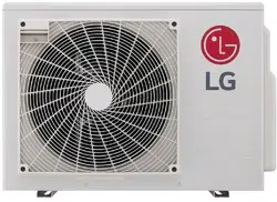
Mode Lock
Prevents mixed mode operation (mode change) in applications
where only one mode is necessary.
1. Shut power down to the system.
2. For Only Cooling Mode Lock, set only DIP Switches 1 and 2 to
ON. For Only Heating Mode Lock, set only DIP Switches 3 and 4
to ON.
3. Turn power on to the system.
Only Cooling Mode Lock Only Heating Mode Lock
Figure 125: Mode Lock DIP Switch Settings.
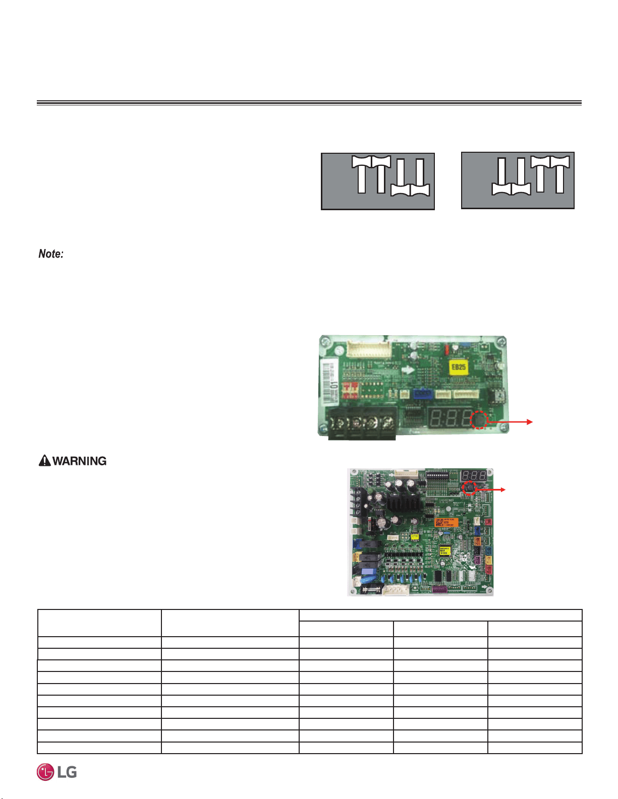
PCB Display (Multi F LMU18-24*HV
and LMU600HV Models Only)
For Multi F LMU18*HV, LMU24*HV, and LMU600HV outdoor units,
the cycle data can be checked without using LG Monitoring View
(LGMV) Diagnostic Software by pushing TACT-SW1. See below
for the types of cycle information that will be displayed in LGMV.
After first page is displayed, the second page will be subsequently
displayed.
3URWHFW¿QJHUVKDQGVZLWKDQRQFRQGXFWLQJPDWHULDOEHIRUHSXVKLQJ
TACT-SW1. There is risk of physical injury or death due to electric
shock.
TACT-SW1
No. of Pushes
Description
Display
Example First Page Second Page
One (1) Time Low Pressure 890kpa “LP” “89”
Two (2) Times High Pressure 2,900kpa “HP” “290”
Three (3) Times Discharge Temperature & “DS” “85”
Four (4) Times Condenser Outlet Temperature & “CS” “-10”
Five (5) Times Suction Temperature & “SS” “-10”
Six (6) Times Outdoor Unit Air Temperature & “AS” “-10”
Seven (7) Times Current 15A “A” “15”
Eight (8) Times Voltage 230V “V” “230”
Nine (9) Times Compressor Hz 100Hz “F” “100”
Ten (10) Times DC Link Voltage 230V “dc” “230”
Table 41: PCB Display Information.
TACT-SW1
Figure 126: Location of TACT-SW1 (LMU18-24*HV).
2QO\WKH¿UVWIRXU',3VZLWFKHVDUHXVHGWRVHWVHWWLQJVDQGIXQFWLRQV
Figure 127: Location of TACT-SW1 (LMU600HV).
TACT-SW1
12 43
12 43
ON
OFF
12 43
12 43
ON
OFF
',36ZLWFK6HWWLQJVIRU2SWLRQDO0RGHV
Loading ...
Loading ...
Loading ...