Loading ...
Loading ...
Loading ...
58
MULTI F / MULTI F MAX Outdoor Unit Installation Manual
Due to our policy of continuous product innovation, some specifications may change without notification.
©LG Electronics U.S.A., Inc., Englewood Cliffs, NJ. All rights reserved. “LG” is a registered trademark of LG Corp.
MULTI
F
MAX
MULTI
F
INSULATION
General Piping System Insulation
All refrigerant piping from the outdoor unit to the indoor units /
branch distribution units (Multi F MAX systems only) must be insu-
lated correctly for safety and usage. Y-branch connections, refrig-
erant piping, field-provided isolation ball valves (if present), service
valves, and elbows must be properly and completely insulated using
closed cell pipe insulation (up to the indoor unit piping connections).
To prevent heat loss / heat gain through the refrigerant piping, all
refrigerant piping including liquid lines and vapor lines must be
insulated separately. Insulation must be a minimum 1/2 inches thick,
and thickness will need to be increased based on ambient conditions
and local codes. Table on the next page lists minimum wall thick-
ness requirements for Ethylene Propylene Diene Methylene (EPDM)
insulation.
)RULQIRUPDWLRQUHJDUGLQJLQVXODWLRQIRUXQGHUJURXQGRUSHQHWUDWLRQVLWXDWLRQVVHHWKH³*HQHUDO5HIULJHUDQW3LSLQJ6\VWHP,QIRUPDWLRQ´VHFWLRQ
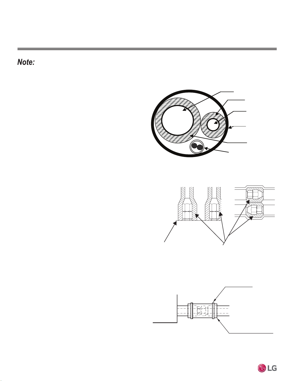
Vapor Line
Liquid Line
Communication /
Connection (Power) Cable
Pi
p
e Sleeve
Insulation Material
Insulation
Material
Figure 64: Typical Pipe Insulation, Power Wire and Communications
Cable Arrangement
,QVLGHWKHRXWGRRUXQLWPD[LPXPSLSHWHPSHUDWXUHLV)DQG
PLQLPXPSLSHWHPSHUDWXUHLV))RUILHOGLQVXODWLRQRIUHIULJHUDQW
piping between outdoor units and indoor units, consider the following
pipe temperature ranges for an operating heat pump system:
• +HDWLQJPRGHUHIULJHUDQWWHPSHUDWXUHUDQJHV/LTXLG)
+LJK3UHVVXUH9DSRU)
• &RROLQJPRGHUHIULJHUDQWWHPSHUDWXUHUDQJHV/LTXLG)
/RZ3UHVVXUH9DSRU)
All insulation joints must be glued with no air gaps. Insulation
material must fit snugly against the refrigeration pipe with no air
space between it and the pipe. Insulation passing through pipe
hangers, inside conduit, and/or sleeves must not be compressed.
Protect insulation inside hangers and supports with a second layer.
All pipe insulation exposed to the sun and outdoor elements must
be properly protected with PVC, aluminum vapor barrier, or alterna-
tively placed in a weather-resistant enclosure such as a pipe rack
with a top cover; and meet local codes. LG-provided Y-branches
are shipped from the factory with pre-formed peel-and-stick foam
insulation jackets, with a 1.84 lb./ft.
3
density, 1/2 inch thickness, and
meet UL94 MF-1 flammability.
The design engineer must perform calculations to determine if the
factory-supplied insulation jackets are sufficient to meet local codes
and avoid sweating. Add additional insulation if necessary. Check
the fit of the insulation jacket after the Y-branch fitting and all run-out
pipes are installed.
Figure 65: Typical Insulation Butt-Joint at
Indoor Unit Casing.
Figure 66: Typical Refrigerant
Flare Fitting Insulation Detail.
Surface of
Indoor Unit Casing
Field-Provided
Pipe Insulation
Figure 67: Insulating the Shut Off / Isolation Ball Valve (If Present).
Indoor Unit
Insulation (Field Supplied)
Cable Tie, etc.
(Field Supplied)
Refrigerant Piping
Loading ...
Loading ...
Loading ...