Loading ...
Loading ...
Loading ...
* Remove return rollers. Pry roller supports up and out of
cap. Remove set screw from each column beneath cap
(see Figure 28).
Cap
RollerJ
Figure 28 - Loosen Cap
• Remove the depth control knob (see Figure 16, page 8).
Lift cap slightly and remove the side cover.
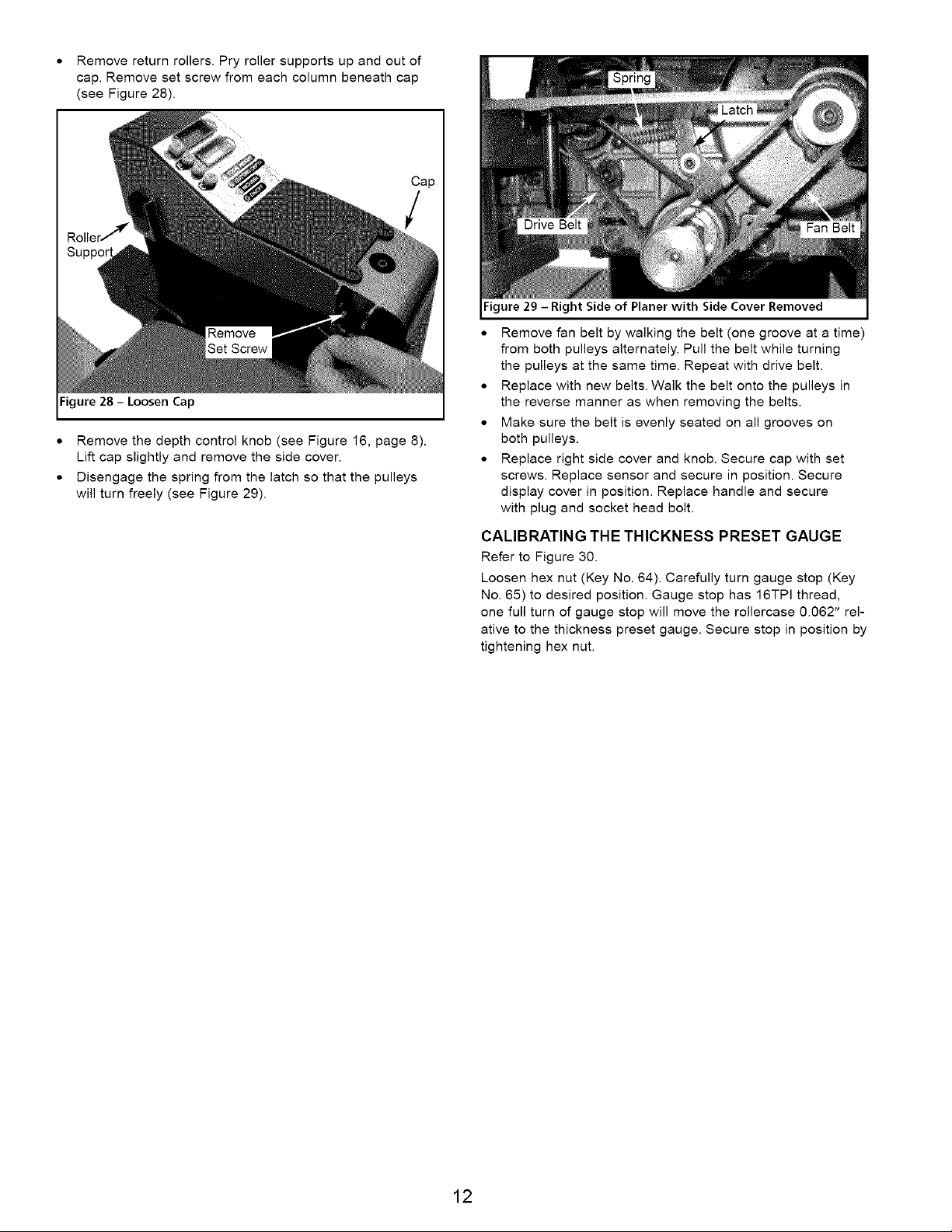
• Disengage the spring from the latch so that the pulleys
will turn freely (see Figure 29).
Drive Belt
Fan Belt
Figure 29 - Right Side of Planer with Side Cover Removed
• Remove fan belt by walking the belt (one groove at a time)
from both pulleys alternately. Pull the belt while turning
the pulleys at the same time. Repeat with drive belt.
• Replace with new belts. Walk the belt onto the pulleys in
the reverse manner as when removing the belts.
• Make sure the belt is evenly seated on all grooves on
both pulleys.
• Replace right side cover and knob. Secure cap with set
screws. Replace sensor and secure in position. Secure
display cover in position. Replace handle and secure
with plug and socket head bolt.
CALIBRATING THE THICKNESS PRESET GAUGE
Refer to Figure 30.
Loosen hex nut (Key No. 64). Carefully turn gauge stop (Key
No. 65) to desired position. Gauge stop has 16TPI thread,
one full turn of gauge stop will move the rollercase 0.062" rel-
ative to the thickness preset gauge. Secure stop in position by
tightening hex nut.
12
Loading ...
Loading ...
Loading ...