Loading ...
Loading ...
Loading ...
ADJUSTING ROLLERCASE LEVEL
Refer to Figure 24.
The planer will produce an uneven depth of cut (tapered cut)
if roliercase is not parallel with base. To restore parallelism
of rollercase with base:
• Using a test piece, measure height of the taper. Determine
which corner or side needs adjustment.
• Turn planer off and disconnect from power source.
• Fold front and rear extension tables.
• Lay planer carefully on its back so that bottom side of
base is facing you.
• Loosen two socket head bolts on the idler bracket. Loosen
chain by sliding idler bracket.
• Carefully rotate the sprocket by hand to change the
rollercase height. Be sure to leave the other sprockets
untouched. Do not rotate sprocket more than one or two
teeth. Movement of one sprocket tooth relative to the
chain moves the rollercase approximately 0.006".
• Retighten chain by securing idler bracket in position.
Tighten socket head bolts securely.
• Set planer back on its base.
• Make a test cut to verify adjustment.
Figure 24 - Adjust Rollercase Level to Base.
Check and Lube Chain
BRUSH INSPECTION AND REPLACEMENT
WARNING: Turn planer off and disconnect from power source.
Brush life depends on amount of load on motor. Regularly
inspect brushes after 100 hours of use. To inspect brushes:
• Remove the return rollers. Remove three (3) screws
and lift the rollercase cover up from the rollercase
(see Figure 25).
i i¸
Figure 25 - Remove Rollercase Cover
(Return rollers have been removed.)
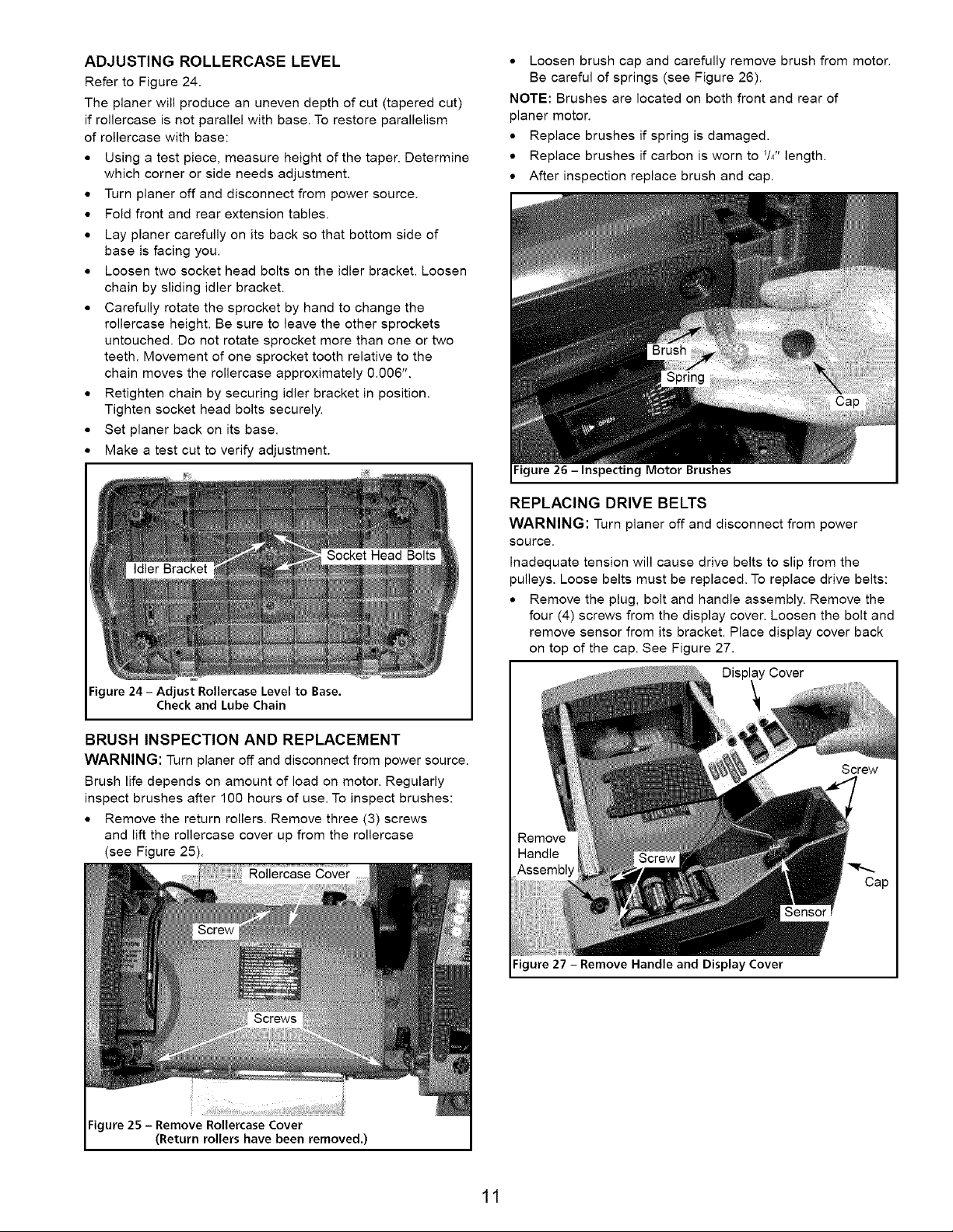
• Loosen brush cap and carefully remove brush from motor.
Be careful of springs (see Figure 26).
NOTE: Brushes are located on both front and rear of
planer motor.
• Replace brushes if spring is damaged.
• Replace brushes if carbon is worn to I/4t' length.
• After inspection replace brush and cap.
Figure 26 - Inspecting Motor Brushes
REPLACING DRIVE BELTS
WARNING: Turn planer off and disconnect from power
source.
Inadequate tension will cause drive belts to slip from the
pulleys. Loose belts must be replaced. To replace drive belts:
• Remove the plug, bolt and handle assembly. Remove the
four (4) screws from the display cover. Loosen the bolt and
remove sensor from its bracket. Place display cover back
on top of the cap. See Figure 27.
Cover
Remove
Handle
Assembly
Figure 27 - Remove Handle and Display Cover
11
Loading ...
Loading ...
Loading ...