Loading ...
Loading ...
Loading ...
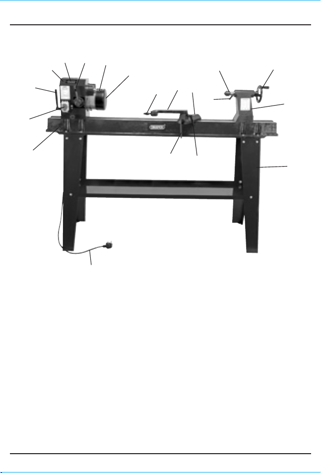
6. TECHNICAL DESCRIPTION
6.1 IDENTIFICATION
Bed.
ON/OFF switch.
Locking lever.
Headstock.
Digital speed display.
Speed change lever.
Drive spur.
Motor.
Tool rest.
Tool rest extension.
Tool rest bolt.
Locking tailstock bolt.
Live centre.
Tail spur adjustment knob.
Tailstock.
Stand.
Tool rest locking bolt.
Locking handle.
Cable and non re-wireable plug.
Hex. keys.
Spanners.
Push rod.
Face plate.
Tool rest.
- Blank page -- Blank page -
7. UNPACKING & CHECKING
7.1 PACKAGING
Carefully remove the product from the packaging and examine it for any sign of damage
that may have happened during shipping. Lay the contents out and check them against
the parts shown below. If any part is damaged or missing; please contact the Draper
Helpline (the telephone number appears on the Title page) and do not attempt to use the
product.
The packaging material should be retained at least during the guarantee period: in case
the machine needs to be returned for repair.
Warning! Some of the packaging materials used may be harmful to children. Do not leave
any of these materials in the reach of children.
If any of the packaging is to be thrown away, make sure they are disposed of correctly;
according to local regulations.
7.2 WHAT´S IN THE BOX?
As well as the lathe; there are several parts not fitted or attached to it.
10. BASIC WOOD TURNING
10. BASIC WOOD TURNING
FIG.27
If the tool rest is positioned too far away from the
workpiece as shown in (Fig.27), the chisel, when correctly
held will again be too high on the workpiece. You will also
find that you have less leverage on your side of the tool
rest and it will be very difficult to hold the chisel.
With a large diameter workpiece, the tool rest can be
above the workpiece centre line and further out from the
surface of the workpiece than normal (Fig.28).
With a small diameter workpiece, the tool rest should be
closer to the surface workpiece than normal. As the
workpiece gets smaller the rest should be repositioned
(Fig.29).
10.6 POSITIONING THE TOOL REST FOR
CIRCUMFERENCE SCRAPING - FIGS. 29 - 32
When scraping, the position of the tool is not as critical as
it is for cutting operations. The chisel is normally held
horizontally, although it can be held at an angle to reach
difficult places. The wire edge of the chisel does the
scraping. Fig.30 and 32 show the result of a chisel being
too low or too high. Fig.31 shows the chisel positioned
correctly on the tool rest.
FIG.28
FIG.30
FIG.29
FIG.32
FIG.31
Handle
kicked up
Large
diameter
Small
diameter
No stock
removed
Edge digging in
FIG.33
10.7 POSITIONING CHISEL AND TOOL REST FOR
DIAMETER SCRAPING - FIGS. 33 - 34
When diameter scraping, the area to the right of the centre
is moving upward (Fig.33). If the chisel is placed in this area
it will simply be carried up and off the tool rest, possibly
out of your hands. So all diameter approach operations
MUST be done at the left of the centre.
Three different chisel contact points are shown (Fig.34).
Note that when the chisel is positioned above or below the
workpiece centre, the work surface sweeps past the chisel
edge at an angle and will tend to carry the chisel in one
direction along the tool rest.
Only when the chisel contacts the workpiece centre line
does the workpiece pass squarely under the edge of the
chisel. This then is the position in which it is easiest to hold
the chisel steady. To obtain the position place the rest
approximately 3mm below the centre.
10.8 USING THE GOUGE CHISEL - FIGS. 35 - 36
Three gouges 6, 12, 18mm sizes are usually sufficient for
home workshop turning, but other sizes are available (refer
to Draper Catalogue). A gouge chisel is normally used for
rough circumference turning or turning raw stock down to
a cylinder of workable size. It is best used for rapid removal
of the workpiece, but will not produce such a smooth
finish, but with practice it can be used for cutting coves, for
shaping long cuts and is also useful for scraping.
When used for cutting, the gouge is always held with the
convex side down and should be rolled approximately 30°
to 45° in the direction in which it is being advanced along
the rest, the cutting edge would be a little in advance of
the handle, Figs. 35 & 36.
FIG.34
FIG.35
FIG.36
Tool
rest
Tool
rest
Cutting edge
advanced
Wrong Correct
10A10B
19
9B9A
20
Loading ...
Loading ...
Loading ...