Loading ...
Loading ...
Loading ...
9. SETTING THE WOOD LATHE
10. BASIC WOOD TURNING
FIG.15
FIG.16
FIG.17
FIG.11
FIG.12
FIG.13
9.5 MOVING THE TAILSTOCK - FIG. 11
To slide the tailstock along the bed, loosen lever .
Once set in position, lock in place by tightening lever
. To move live spur in and out with the barrel, loosen
locking lever and rotate wheel . Once the position
is set, lock in place using lever .
9.6 ADJUSTING THE TOOL REST - FIG. 12
To move the tool rest along the bed, slide it back and
forth or rotate loosen handle . To angle or change the
height, of the tool rest, loosen handle . This set
up with the tool rest will provide for most of your needs.
However, should it be required for bowl turning etc, there
is an extension provided. This fits by loosening handle
. Remove the tool rest and replace with the extension.
Loosen handle on the extension and slide in tool rest.
When fully adjusted, make sure all of the locking handles
are secured.
9.7 CHANGING THE BELT - FIG. 13
Make sure the lathe is in speed position 1. Switch off
power supply and remove the plug. Remove the pulley
cover. Insert a disc (the size of a two pence piece) between
the two halves of the motor pulley and between the belt
runs. Slowly rotate the drive spindle back and forth by
hand while turning the speed lever slowly to a higher
speed. When maximum speed has been reached on the
lever, the belt can be removed easily. Fit a new belt over
both pulleys. Slowly rotate the drive spindle back and
forth by hand while turning the speed lever slowly to the
slowest speed. When speed 1 is reached, the disc may be
removed and pulley cover replaced.
The following pages of this manual explain and illustrate
the correct use of the turning tools, the tool rest and
other information to help you.
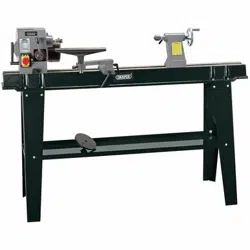
10.1 SPINDLE TURNING - FIGS. 15 - 18
Select a piece of wood 50x50x300mm (approx.) Draw
diagonal lines on each end the piece of wood to locate
the centres (Fig.7).
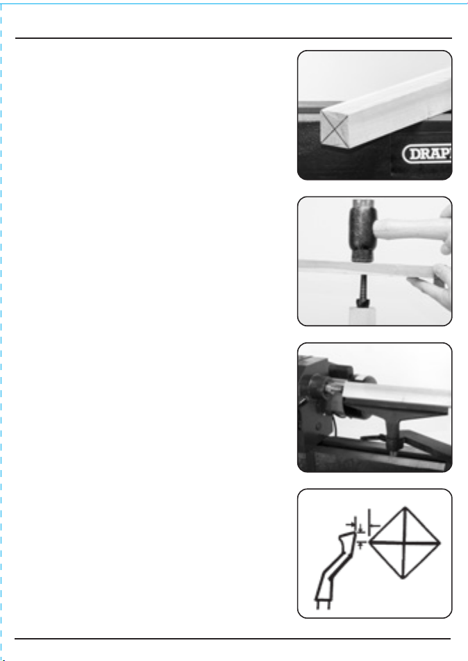
In both ends of the piece of wood drill a 1.5mm hole,
7mm deep into the centre. Now secure the workpiece in a
soft jaw vice. Put the point of the drive spur into the
drilled hole and tap the spur in securely (Fig.8).
Now remove the spur and check the prongs have left an
imprint.
Ensure that both the drive spur and live centre are clean
and insert them into the lathe (see page 7). Place the
workpiece between the centres and close up the tailstock
(Fig.9) making sure the marked end goes the tailstock
end.
Select the required tool rest position approx 3mm away
from the corners of the wood and 3mm above the centre
line (Fig.10) and lock the tool rest into position. Now
select the appropriate speed (see Page 8), rotate the
workpiece to check the corners do not foul the tool rest.
FIG.18
Tool Rest
3mm
3mm
Wood
15
14
Loading ...
Loading ...
Loading ...