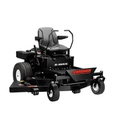
ZT2452A
24 HP - 52" CUT
CELEBRATING 65 YEARS OF INNOVATION
SINCE 1945
1602 CORPORATE DRIVE, WARRENSBURG MISSOURI 64093
PHONE: (660) 747-8183 FAX: (660) 747-8650
MANUFACTURING QUALITY LAWN CARE EQUIPMENT SINCE 1945
OWNER'S MANUAL
STARTING SERIAL # L110-006001
17469 REV. 10-088
MADE IN THE
USA

The manufacturer’s warranty to the original consumer purchaser is: This product is free from
defects in materials and workmanship for a period of two (2) years from the date of purchase
by the original consumer purchaser. We will repair or replace, at our discretion, parts found to
be defective due to materials or workmanship. This warranty is subject to the following
limitations and exclusions:
1) Engine Warranty
All engines utilized on our products have a separate warranty extended to them by the
individual engine manufacturer. Any engine service difficulty is the responsibility of the engine
manufacturer and in no way is Swisher or its agents responsible for the engine warranty.
The Briggs & Stratton Engine Service Hot-Line is 1-800-233-3723.
2) Commercial Use
This product is not intended for commercial use and carries no commercial warranty.
3) Limitation
This warranty applies only to products which have been properly assembled, adjusted, and
operated in accordance with the instructions contained within this manual. This warranty does
not apply to any product of Swisher that has been subject to alteration,
misuse, abuse, improper
assembly or installation, shipping damage, or to normal wear of the
product.
4) Exclusions
Excluded from this warranty are normal wear, normal adjustments, normal maintenance, and
battery
*
(see battery section.)
222-8183.
The model number, serial number, date of purchase, and the name of the
authorized Swisher dealer from whom you purchased the mower will be needed before
any warranty claim can be processed.
THIS WARRANTY DOES NOT APPLY TO ANY INCIDENTAL OR CONSEQUENTIAL
DAMAGES AND ANY IMPLIED WARRANTIES ARE LIMITED TO THE SAME TIME
PERIODS STATED HEREIN FOR ALL EXPRESSED WARRANTIES.
Some states do not
limited warranty as defined by the Magnuson-Moss Act of 1975.
LIMITED WARRANTY
17469 2 REV. 10-088

LIMITED WARRANTY
....................2
TABLE OF CONTENTS
..................3
INTRODUCTION
..........................4-5
General....................................4
Before Operating.....................4
Uncrating & Assembly.............5
TABLE OF CONTENTS
17469 3 REV. 10-088
SYMBOLS AND DECALS
.............
6
SAFETY INSTRUCTIONS
...............
7
General use & Safety rules.....7
Child Safety & Slope...............8
Precautions.............................8
CUSTOMER
RESPONSIBILITY
........................10-13
Operator Presence..................10
Tires.........................................10
Blade Maintenance..................10
Battery.................................10-11
V-Belts......................................12
Engine......................................12
Overall Unit Care......................12
Transporting Safety..................12
Specifications...........................12
Maintenance.............................13
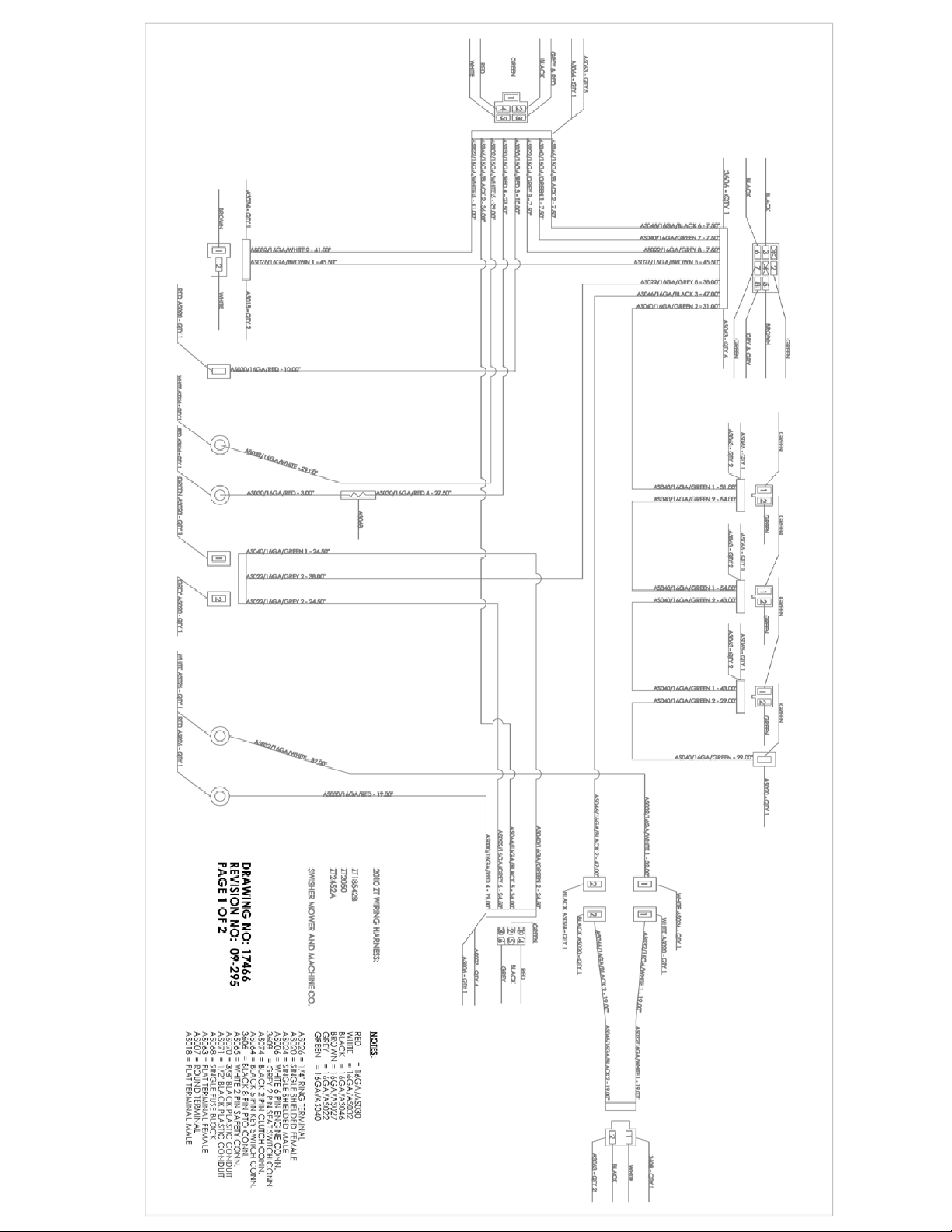
WIRING SCHEMATIC
...............22-23
PARTS BREAKDOWN
...............24-35
TROUBLESHOOTING
................36-37
MOWER IDENTIFICATION
............38
WARRANTY RIGHTS
......................39
SWISHER HISTORY
........................40
SERVICE & ADJUSTMENTS
...........18
Adjust Deck Height..................18
Deck Level...............................18
Parking Brake..........................18
Deck Belt Replacement.......19-20
Hydro Belt Replacement.....19-20
Seat Adjustment.......................21
Travel Adjustment....................21
OPERATION
................................14-17
Features...............................14-15
Starting....................................16
Grass Height of Cut.................16
Parking Brake..........................16
Controls...................................17

CONGRATULATIONS!
Thank you for purchasing a Swisher Zero Turn mower. This machine is built for the greatest
transmissions regulated by steering levers, contribute to the machine’s performance.
This manual is a valuable document. Following the instructions for use, service,
maintenance, etc. can greatly increase the life-span of your machine .
GENERAL
:
In this operator’s manual, left and right, backward and forward are used in relation to the
normal operators position.
READ BEFORE OPERATING
:
This machine is constructed only for mowing grass on lawns and other free and even ground
without obstacles. This machine is not intended for commercial use. The manufacturer’s
directions concerning operation, maintenance, and repairs must be carefully followed.
the machine’s special characteristics and who are well versed in safety instructions.
and traffic regulations must be followed without fail.
Unauthorized modifications to the design of the machine may absolve the manufacturer from
liability for any resulting personal injury or property damage.
~Read the engine manufacturer’s operating and maintenance instructions.
~Read and observe all safety instructions on your mower and in the manual.
~Check the engine oil.
~Check the fuel cap to be sure that it is tight and in place.
~Know how to set the parking brake.
~Be sure the mower blades are turned off – PTO switch pushed down.
~Know how to stop the engine – Turn the key to off
~Know how to stop the unit – Return control handles to neutral
~Know the process of how to start the engine
INTRODUCTION
17469 4 REV. 10-088
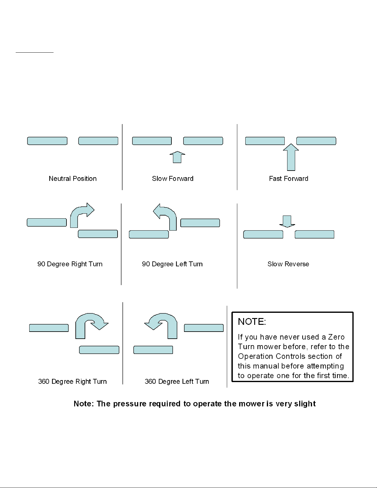
NOTE:
If you have never used a Zero Turn mower
before, refer to the Operation Controls
section of this manual before attempting to
operate one for the first time.

UNCRATING AND ASSEMBLY
Tools Required
:
~2 - ½” Wrenches or ½” Socket with drive ratchet
~Tire pressure gauge
~Nail bar or claw hammer
~Wire snips
To Remove The Mower From The Crate
:
~Dispose of top and side panels of the crate.
~Remove loose parts and packing material.
~Cut any banding or strapping that may be holding the mower to the crate.
~Disengage spark plug wire and place where it cannot make a connection.
~Raise the mower deck to its highest position.
~Install steering levers. Remove the bolts from the control arms on the mower. Align the holes
in the lever with the holes in the control arms and attach with the bolts provided.
Make sure
both bolts on both handles are tight.
~Install the seat. Remove the bolts from the seat bracket that is attached to the frame. Line up
the seat bracket and resinstall bolts. Securely tighten. Plug in the lead from the wiring harness
to the bottom of the seat. It may be necessary to move the seat via the seat slide to gain
access to pluging in the connector the seat switch.
the decal.
~Open the transmission valves at the rear of the unit by pulling the release handles and
locking them in place.
SEE INSTRUCTION DECAL AT
THE REAR OF THE UNIT
.
~Carefully push the mower off the crate to a safe and level area.
~Check the engine oil. All engines are filled with oil and tested at the factory. Verify oil level
and add if necessary before starting engine.
SEE ENGINE OWNER’S MANUAL
~Check the battery. If the battery is put into service after the “month & year” of the date on the
more than 2 hours at a rate of 6 to 10 amps.
~Attach battery cables to battery.
Always attach the positive terminal first.
~
Close the transmission valves at the rear of the unit.
SEE INSTRUCTION DECAL AT THE
REAR OF THE UNIT
.
~Reconnect the spark plug wire.
~Check tire pressure on all four wheels.
REFER TO UNIT SPECIFICATIONS TABLE
INTRODUCTION
17469 5 REV. 10-088

SYMBOLS AND DECALS
17469 6 REV. 10-088
SAFETY INSTRUCTIONS
17469 7 REV. 10-088
These instructions are for your safety. Read them carefully.
General Use
~Read all instructions in this operator’s manual and on the machine before starting it. Ensure that you understand
them and then abide by them.
~Learn how to use the machine and its controls safely and learn how to stop quickly. Also learn to recognize the
safety decals.
~Only allow the machine to be used by adults who are familiar with its use.
~Make sure nobody else is in the area of the machine when you start the engine, engage the drive, or run the
machine.
~Stop the machine if someone enters the work area.
~Clear the area of objects such as stones, toys, steel wire, etc. that may become caught in the blades and thrown
out.
~Do Not Use this machine without the Discharge Chute in place.
~Stop the engine and disconnect the spark plug before cleaning the discharge deck.
~Never take passengers. The machine is only intended for use by one person.
~Always look around before and during reversing maneuvers.
~Slow down before turning.
~Shut down the mower deck when not mowing.
~Be careful when rounding fixed objects, so that the blades do not hit them.
~Only operate the machine in daylight or other well-lit conditions.
~Keep the machine a safe distance from holes or other irregularities in the ground.
~Never use the machine if you are tired, if you have consumed alcohol, or if you are taking other drugs or
medications that can affect your vision, judgment, or coordination.
~Beware of traffic when working near or crossing a road.
~Never leave the machine unsupervised with the engine running. Always shut down the blades, engage the
parking brake, stop the engine, and remove the ignition key before leaving the machine.
~Never allow children or other persons not trained in the use of the machine to use or service it. Local laws may
regulate the age of the user.
~Make sure that you have first aid equipment close at hand when using the machine.
~Never use the machine when barefoot. Always wear protective shoes or boots.
SAFETY INSTRUCTIONS
17469 8 REV. 10-088
General Use Continued…
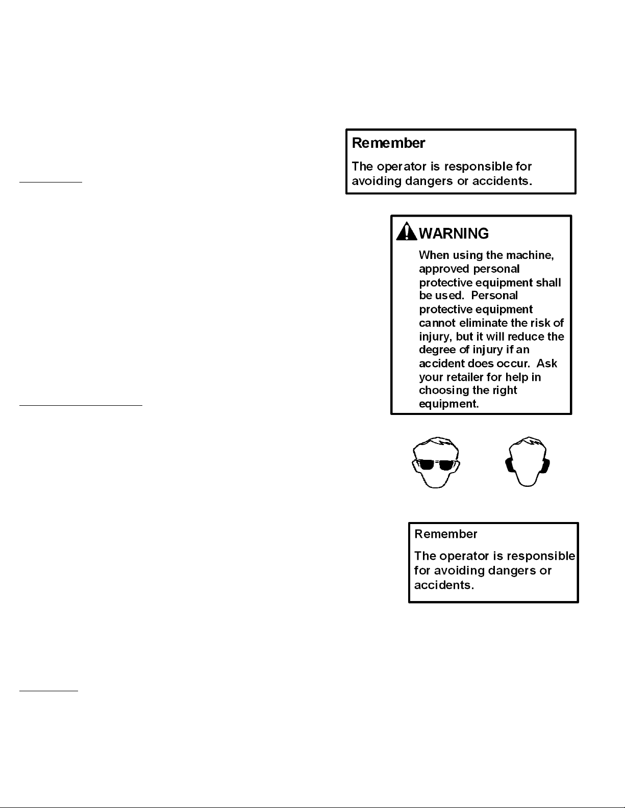
~Always wear approved protective glasses or a full visor when
assembling or driving.
~Ear Protection is recommended
~Never wear loose clothing that can get caught in moving parts.
Children:
~Serious accidents may occur if you fail to be on guard for children
in the area of the machine. Children are often attracted to the
machine and mowing work.
~Never assume that children will stay put where you last saw
them.
~Keep children away from the mowing area and under close
supervision by another adult.
~Shut off the machine if children enter the work area.
~Never allow a child to ride with you.
~Never allow children to operate the machine.
~Be extra cautious near corners, bushes, trees, or other objects
that block your view.
Slope Operation:
~Remove obstacles such as stones, tree branches, etc.
~Mow up and down, not side to side. Never drive the rider on
terrain that slopes more than 10 degrees.
~Avoid starting or stopping on a slope. If the tires begin to slip,
shut down the blades and drive slowly down the slope.
~Always drive evenly and slowly on slopes.
~Make no sudden changes in speed or direction.
~Avoid unnecessary turns on slopes, and if it proves necessary,
turn slowly and gradually downward, if possible.
~Watch for holes, ruts, or bumps. On uneven terrain, the machine
can tip more easily. Long grass can hide obstacles.
~Drive slowly and use small movements of the steering controls.
Do not mow wet grass. It is slippery, and the tires can loose their
grip, so that the machine slides.
~Do not try to stabilize the machine by putting a foot on the
ground.
Towing:
~This machine is rated at a 50 lb maximum tongue capacity and a
250 lb maximum towing capacity. Powered pull behind
accessories are not recommended for use with this vehicle.
SAFETY INSTRUCTIONS
17469 9 REV. 10-088
17469 10 REV. 10-088
CUSTOMER RESPONSIBILITIES
Operator Presence System
~Be sure the operator presence and interlock systems are working properly. If your mower does not function as described,
repair the problem immediately.
~The engine should not start unless the parking brake is engaged, the control handels are placed in their outward positions,
and the PTO (Blade Engagement – See OPERATION FEATURES section of this manual) switch is disengaged (pressed
down).
~When the engine is running, the operator should never leave the seat without first setting the parking brake and shutting off
the engine.
~When the engine is running and the PTO switch is engaged, any attempt by the operator to leave the seat without first
disengaging the PTO switch, should shut off the engine.
~When the engine is running and the control levers are rotated in, the operator should never attempt to leave the seat without
rotating the control levers out, shutting off the engine and engaging the parking brake.
~The PTO switch should never engage without the operator on the seat.
Tires:
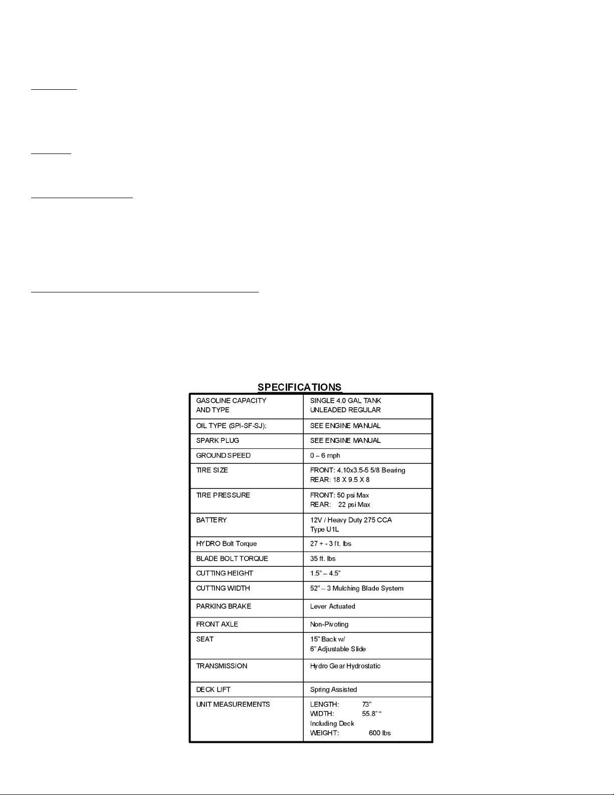
~Maintain proper air pressure in all tires ( SEE SPECIFICATIONS section)
~Keep tires free of gasoline, oil, or insect control chemicals which can harm rubber.
Blade Maintenance:
~Stop the engine and remove ignition key for safety. Disconnect the spark plug wire. Wear heavy, thick gloves when holding
onto blade. Avoid the sharp edge of the blade.
~ For best results, mower blades must be kept sharp. Replace bent or damage blades.
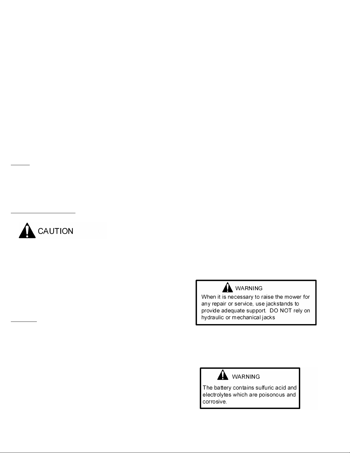
~Safely raise front of mower. SEE WARNING
~Hold or block blade from turning.
~Loosen blade nut and remove blade.
~Replace blade, (SEE SPECIFICATIONS).
Battery:
To clean battery and terminals
~Remove terminal guard.
~Rinse the battery with plain water and dry.
~Clean terminals and battery cable ends with wire brush until shiny.
~Coat terminals with grease or petroleum jelly
~Reinstall battery
~Reconnect the battery cables
17469 11 REV. 10-088
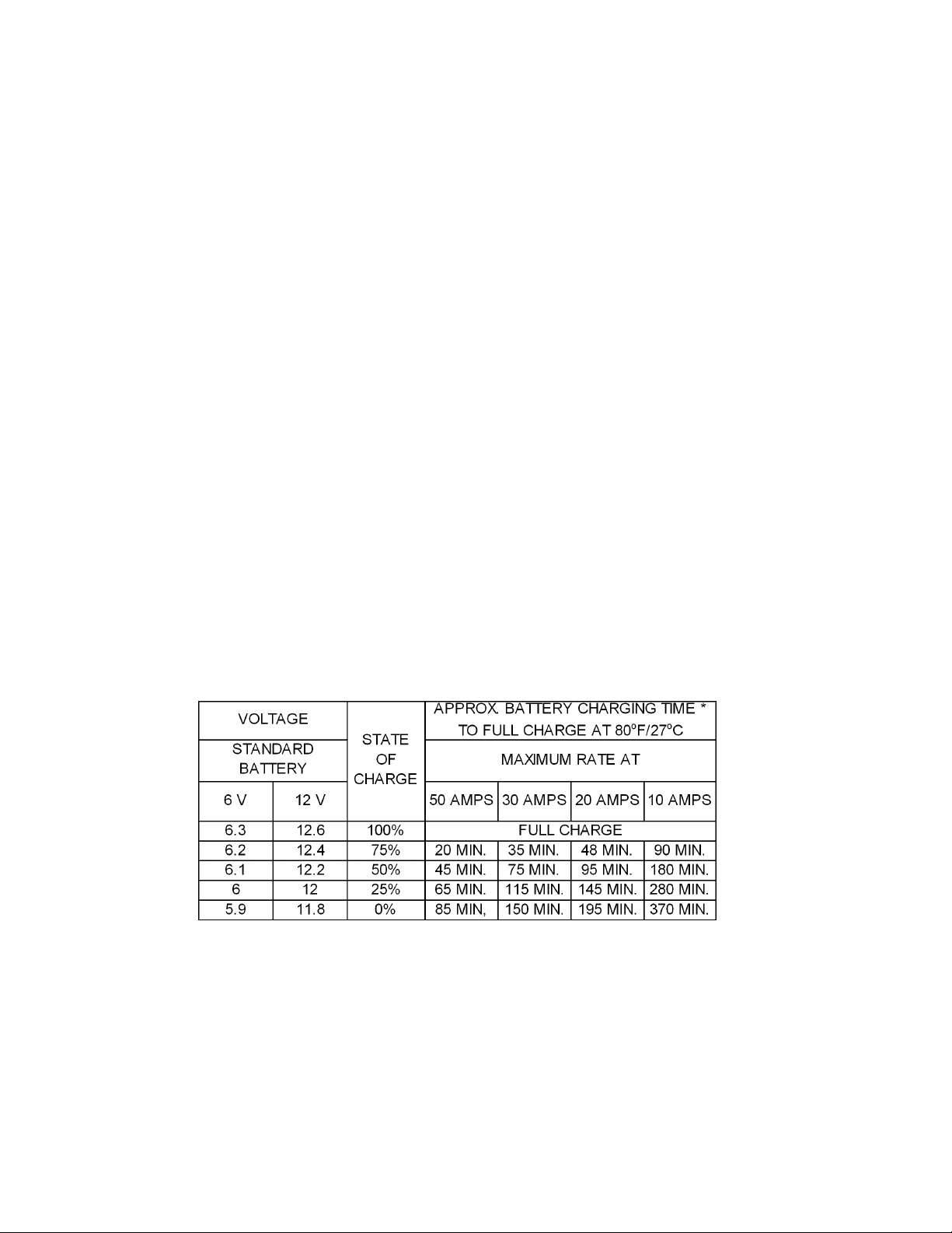
CHARGING TIPS
~To avoid a battery explosion, never attempt to charge a frozen battery.
~Warning:
Gel and AGM (Absorbed Glass Mat) batteries require a voltage-limited charger.
life.
~Important:
Never overcharge batteries. Excessive charging will shorten battery life.
~Prior to charging, read the manufacturer’s instructions for proper charger hook-up and use.
~Turn off charger prior to hook-up to avoid dangerous sparks.
PROTECT YOUR EYES!
~Warning:
At the end of charge, add distilled water as needed to bring levels to the proper height. If water is
added, charge for an additional 30 minutes to mix. If electrolyte levels are low but battery is not
accessible, remove battery from service.
~The maximum charge rate in amperes should be no more than 1/3 of the battery’s reserve capacity
minute rating. If the terminal voltage exceeds 16.0 volts while charging, reduce the charge rate.
~Continue charging and reduce the rate as needed until a 2 hour period results in no increase in
voltage or decrease in current.
~If violent gassing or spewing of electrolyte occurs, or the battery case feels hot to the touch,
temporarily reduce or halt charging.
*
Test wet batteries every 4-6 months and recharge if necessary. Always test and charge if
necessary before installation.
17469 12 REV. 10-088
CUSTOMER RESPONSIBILITIES
V-Belts:
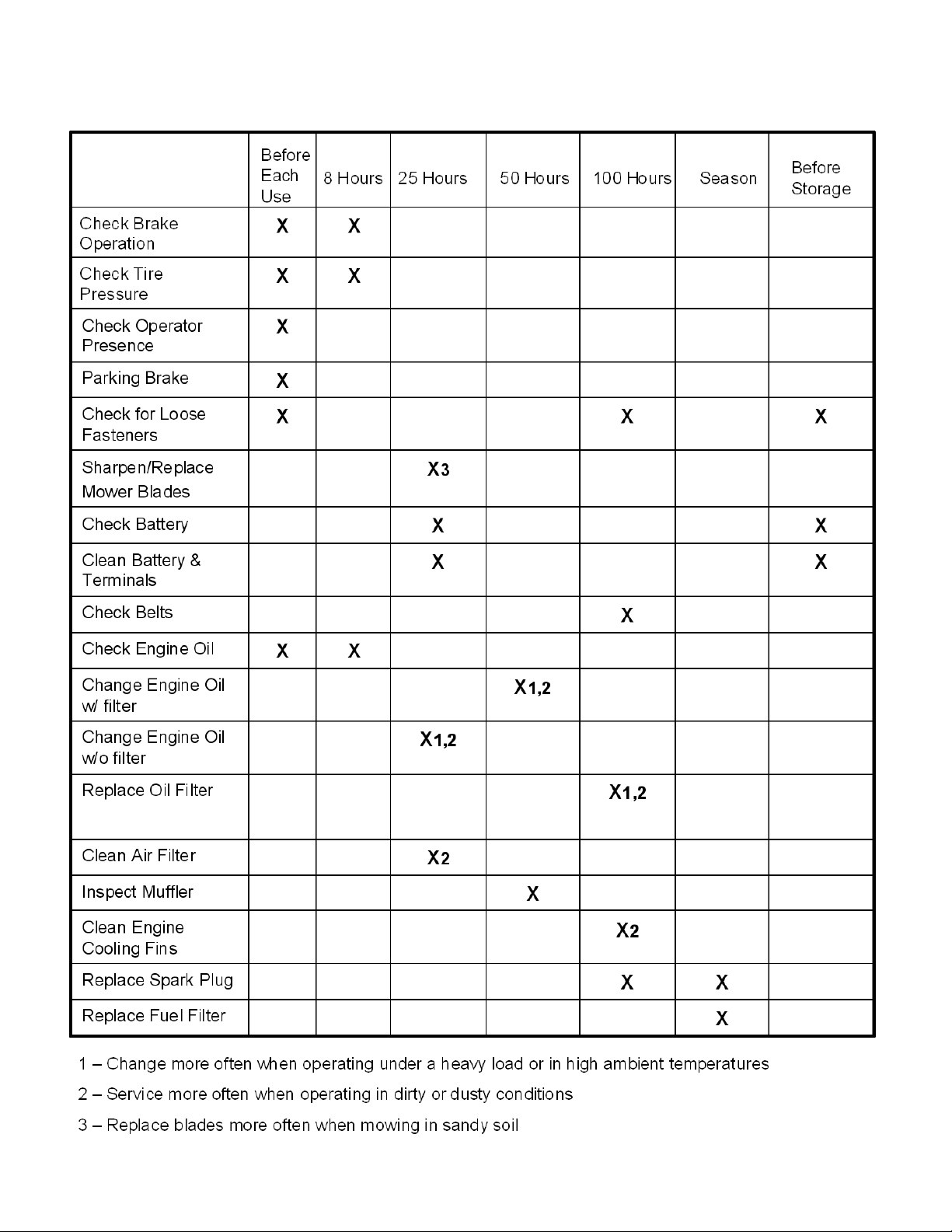
Check V-belts for deterioration and wear every 50 hours of operation and replace if necessary. Replace belts if they begin to
slip from wear. SEE SPECIFICATION for belt part numbers and SERVICE section of this manual for instructions on how to
replace the belt.
Engine
:
REFER TO YOUR ENGINE OWNERS MANUAL
Overall Unit Care:
~Reduce the risk of fire by removing grass, leaves, and other debris that may have accumulated on the machine. Allow the
machine time to cool before cleaning or putting it in storage.
~Wash your mower periodically. Clean above and below deck.
~Keep all electrical connections clean and tight.
Driving and Transport on Public Roads:
~If the machine is transported, you should always use approved fastening equipment and ensure that the machine is well
anchored.
17469 13 REV. 10-088
CUSTOMER RESPONSIBILITIES
MAINTENANCE SCHEDULE

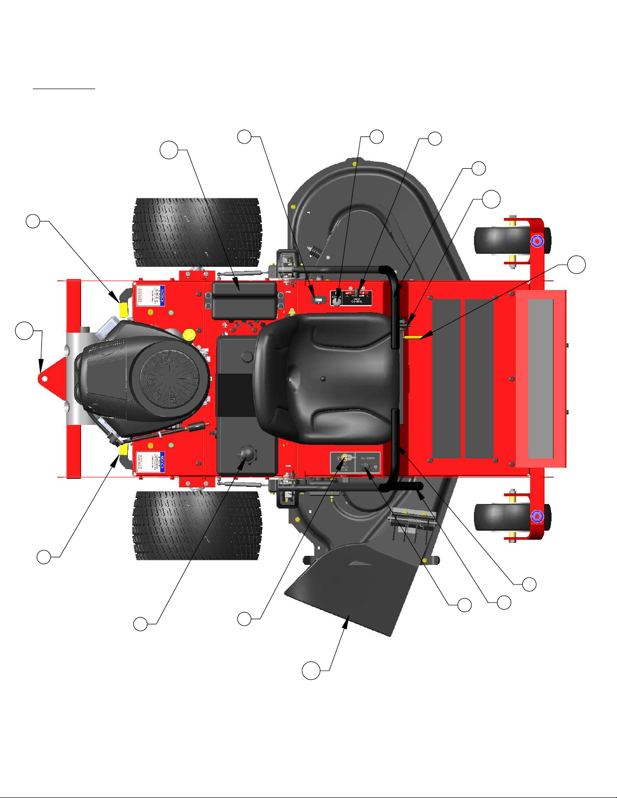
FEATURES
:
(1) Throttle Control (# 4226)– Used to control Engine Speed
(2) Hour Meter (#17635 / 3803) – Indicates hours of operation
(3) Choke Control (# 9914)– Used when starting a cold engine
(4) PTO Switch (# 3605) – Used to engage or disengage the deck blades
(5) Ignition Switch (# 3623) – Used to start or stop the engine
(6) Deck Lift Handle – Used to raise and lower the cutting deck
(7) Control Lever – Sets the speed of the mower in both the forward and reverse directions and also turns the mower.
(8) Hydro Bypass – Engages transmissions for normal operation and disengages transmissions for pushing or pulling the unit
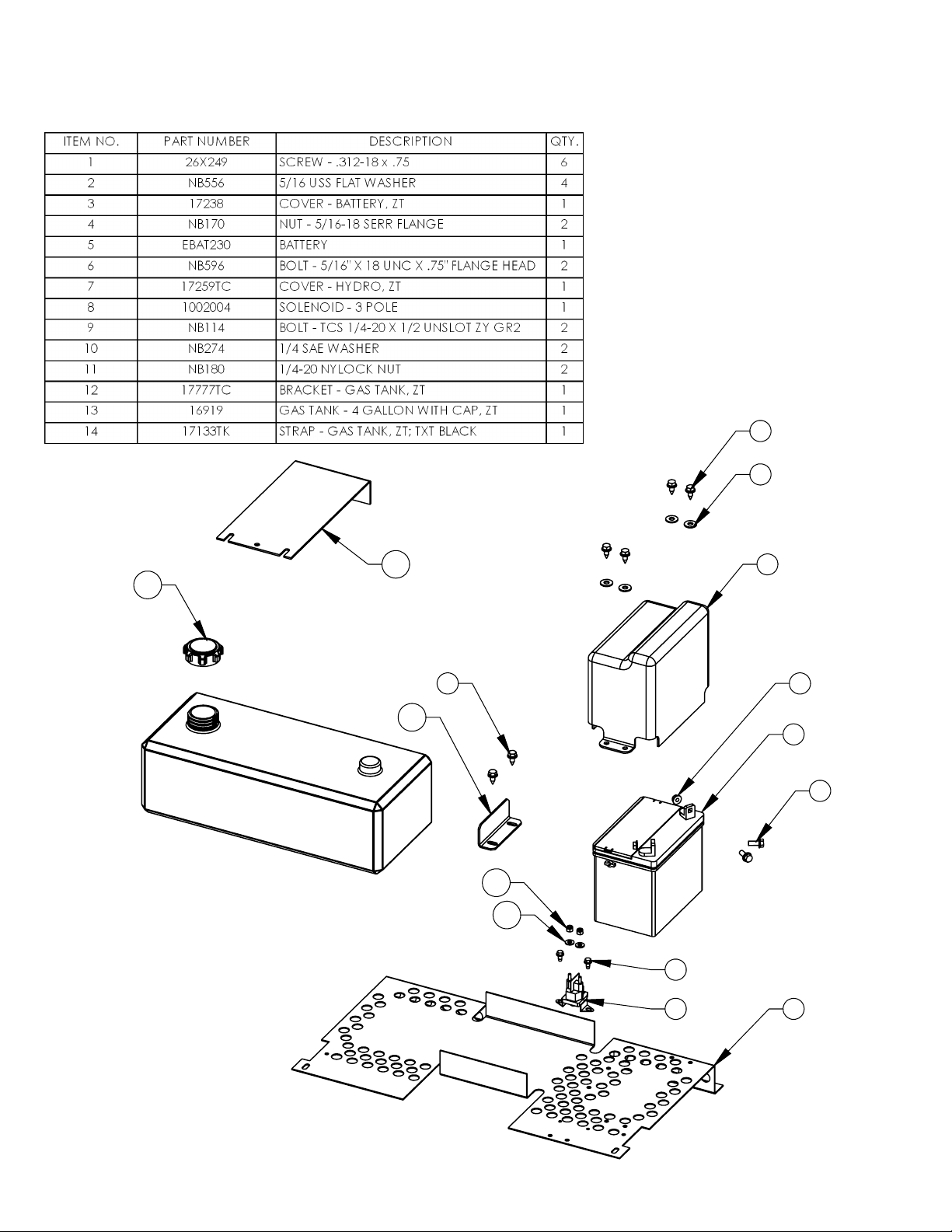
(9) Fuel Tank – Single 4.0 gal fuel tank
(10) Seat Slide (# 12938)
(11) Battery
(12) Discharge Chute
(13) Parking Brake Lever - Must be in the "Engaged" position to start the mower
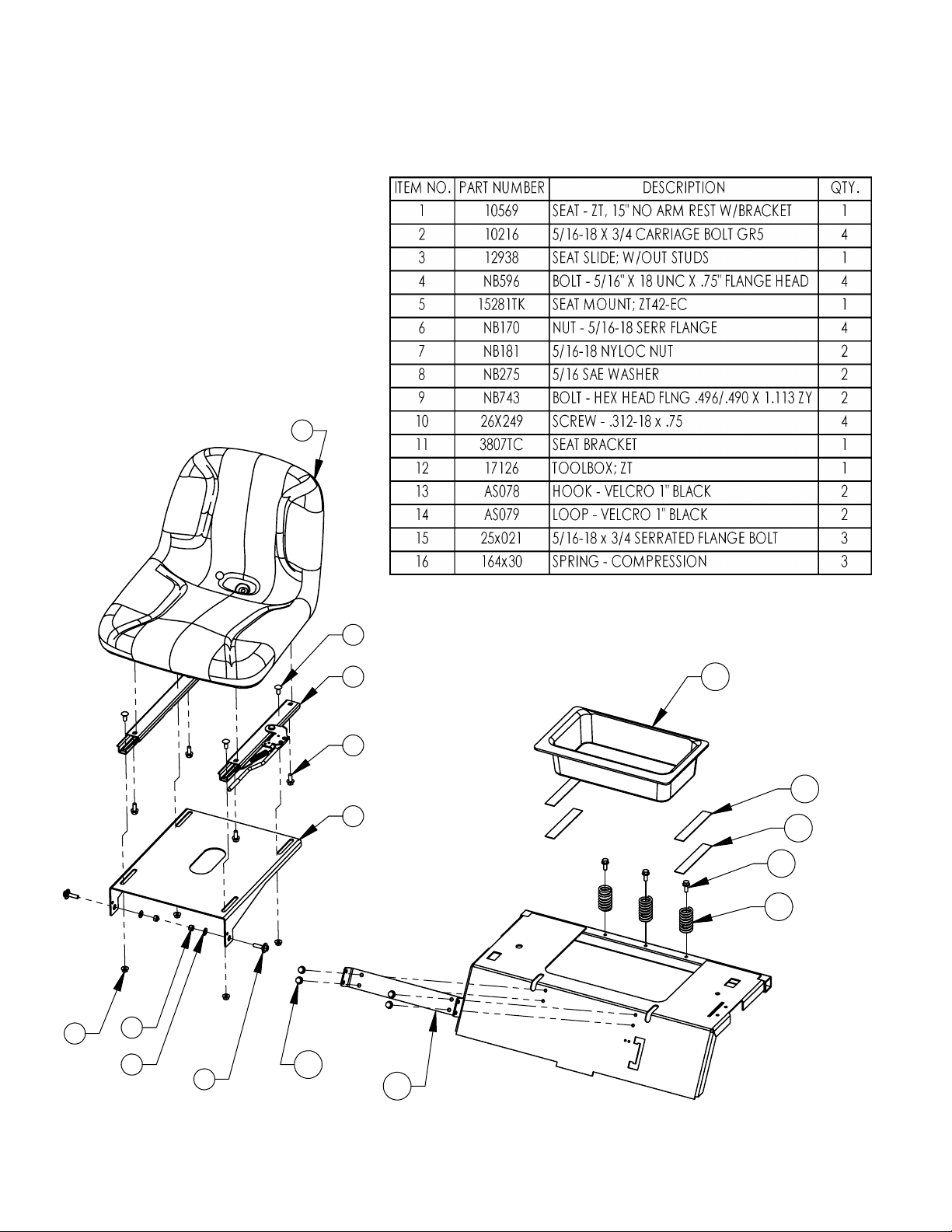
(14) Tool Box - Used for storage under the seat and can be removed for access to belt adjustments and replacement
(15) Tow Hitch
6
7
9
10
12
14
OPERATION
17469 14 REV. 10-088
1
2 3
4
5
6
7
7
8
8
9
10
11
12
13
15
17469 15 REV. 10-088
OPERATION
FEATURES
:

17469 16 REV. 10-088
OPERATION
Starting
:
~Operator must be sitting in the seat. Control handles must be in the neutral (outward) position. PTO
must be in the disengage position (pushed down) and the parking brake must be engaged.
~Set choke (if needed), turn key and release as soon as engine starts. Adjust throttle to half and shut
choke off.
~Be sure all people are clear of the area. Set engine RPM to maximum and then engage the blades.
~Disengage the parking brake and move the handles to start mowing.
Grass Height & Cutting Suggestions
:
~Do not attempt to cut wet grass
~The average lawn should be cut to 2 ½” during the cool season and to over 3” during the hot months.
For healthier and better looking lawns, mow often and after moderate growth.
~As a rule , never cut more than 1/3 of the total grass blade length. Correct mowing height can reduce
weeds and lawn disease.
~For best performance, grass over 6 inches in height should be mowed twice. The first cut should be set
relatively high and the second set to the desired height.
Parking Brake
:
~This machine is equipped with a linkage type mechanical parking brake.
~
It is only a parking brake and not an emergency brake!
~The parking brakes design is such that it has replaceable wear items which should be checked at
regular intervals to observe wear.
~The wear items include the (1) cog wheel and the (2) tooth arm. These items are not included as
warranty items! These are considered normal wear items and must be maintained.
~The parking brake must be kept in proper adjustment at all times to insure proper operation.
17469 17 REV. 10-088
OPERATION
Controls
:
~Be familiar with all controls, their functions and how to operate them before starting the machine.
~Motion control levers on each side of the console control the direction of movement.
SEE THE FIGURE BELOW

17469 18 REV. 10-088
SERVICE AND ADJUSTMENTS
Adjusting The Cutting Height:
~Push out on the Deck Lift Handle and raise or lower the deck to the desired position.
~Position 1 is the lowest setting and Position 8 is the highest position
~The cutting range is from approximately 1 1/2” to approximately 4 1/2”
~Further fine tune the deck cutting height by raising or lowering the deck relative to the lift arm. This can be done by moving
the hole location of 17408TK on both the right and left sides. Simply set the deck lift handle to the desired position, remove
the bolts holding the right and left 17408TK's in place, and re assemble to another hole location in the 17408TK. Make sure
both 17408TK's on your mower are assembled with the same hole location for a level cut. This adjustment will allow you to
vary the lowest or higest deck settings.
Deck Leveling
:
(TOOLS REQUIRED)
~ 2 - ½” Wrenches or ½” Socket with drive ratchet
~ Bubble Level
~Lower the cutting deck down to the lowest position (position 1)
~Loosen the nuts and bolts on the crescent slotted, rear adjustment plates (2 plcs).
~Place the level on a smooth part of the deck shell and with the front rollers on the ground raise or lower the rear of the deck.
~Re-tighten the nuts and bolts on the crescent adjustment places one the desired adjustment is made.
~Lift deck using the deck lift handle to the desired position
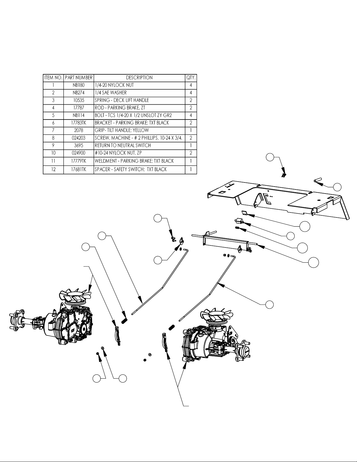
Parking Brake:
~The Swisher ZT2452A is equipped with separate parking brake system.
~The parking brake is actuated with the lever in the front control panel of the mower frame. Up is engaged and down in
disengaged.
~Adjustment for the system is located on the end of the brake linkage near the hydrostats under the rear of the mower.
~Raise both the rear wheels off the ground
~Disengage both hydro's with the hydro release handles at the rear of the unit. Pull the levers to disengage.
~Adjust the parking brake so that the wheels turn freely in the disengage position.
~The wheel should not turn when the handle is moved to the engaged or upward position.
~Lower unit back to the ground
~Re-engage the hydro's at the rear of the unit by pushing the levers inward
.
~
It is only a parking brake and not an emergency brake!
~The parking brakes design is such that it has replaceable wear items which should be checked at regular intervals to
observe wear.
~The wear items include the (1) cog wheel and the (2) tooth arm. These items are not included as warranty items! These
are considered normal wear items and must be maintained.
~The parking brake must be kept in proper adjustment at all times to insure proper o
peration.

17469 19 REV. 10-088
SERVICE AND ADJUSTMENTS
(REFER TO THE BELT ROUTING DIAGRAMS ON THE NEXT PAGE)
Deck Belt Routing & Replacement
:
Removal
~Apply the parking brake
~Disconnect the spark plug wire
~Lower the deck to its lowest position
~Remove the belt covers and floorboard access panel
~Disconnect tension idler
~Roll the belt over the top of the deck pulleys
~Remove belt
Replacement
~Install new belt by placing it around the deck pulleys. Refer to routing diagram on the next page
~Tightly secure the deck belt idler tension nut back to its original position
~Reinstall the belt covers
~Reconnect spark plug wire
Hydro Belt Routing & Replacement
:
Removal
~Apply the parking brake
~Disconnect the spark plug wire
~Lower the deck to its lowest position
~Flip the seat forward and remove the tool box from its Velcro connection and set aside
~Remove the floorboard access panel
~Disconnect wiring connector to the electric clutch
~Remove clutch stop bracket
~Loosen the hydrostat belt sliding idler spring tension nut
~Loosen the deck belt idler tension nut
~Remove the engine to deck belt
~Remove the belt from the engine pulley and from the hydro pulleys
Replacement
~Install new belt by placing it around the engine pulley and the hydro pulleys. Refer to the routing
diagram on the next page.
~Tightly secure the belt tension back to its original position
~Reinstall the belt from the engine to the deck
~Retighten the deck belt idler tension nut
~Reassemble the clutch stop bracket
~Reconnect the wiring connector to the electric clutch
~Replace the floorboard access panel, the tool box and flip the seat back
~Reconnect the spark plug wire
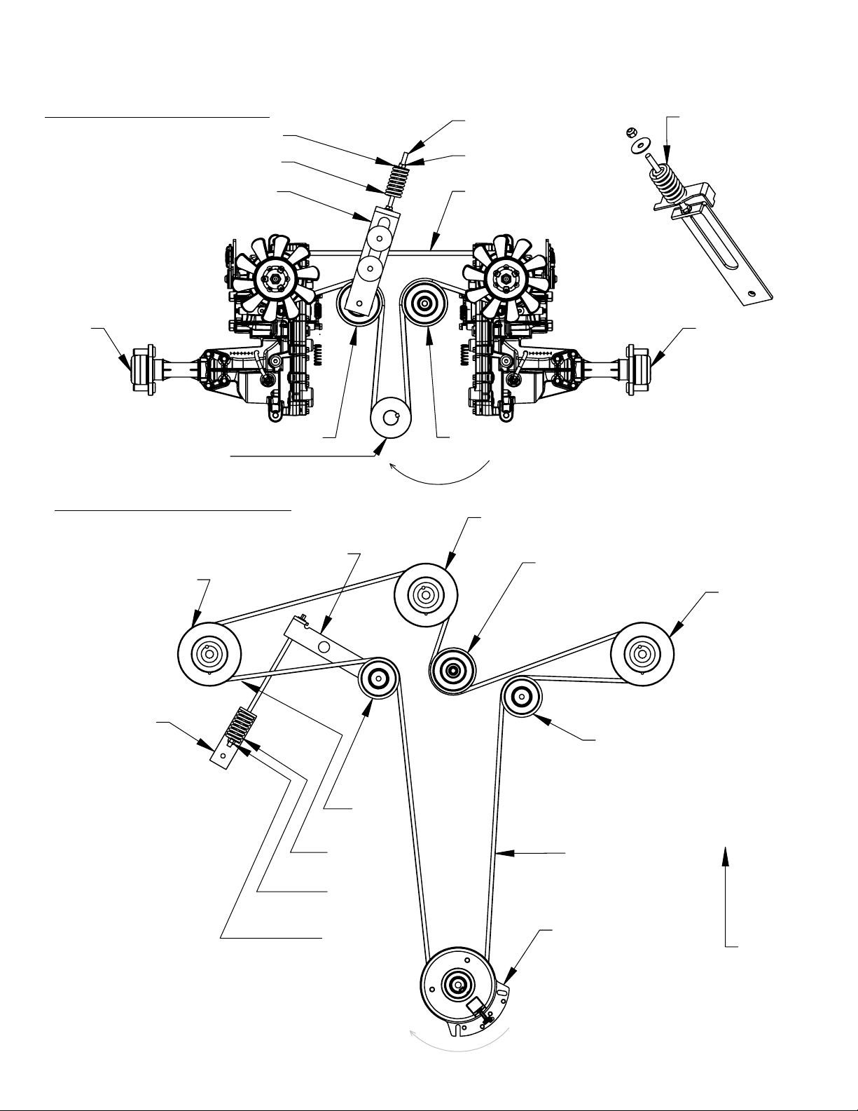
17319
RH
Hydrostat
17320
LH
Hydrostat
4220 V-Belt
14392 Engine Pulley
B527 Pulley B527 Pulley
16825TK Idler
164X30 Spring
NB579 Washer
NB181 Nut
NB660 Bolt
Rotation
B527
Pulley
95309
Pulley
95309
Pulley
95309
Pulley
14335
Clutch
7509
Pulley
7509
Pulley
3816 V-Belt
Front of
Mower
17493TK
Idler Arm
17645TK
Bracket
10636YZ
Rod
164X30
Spring
NB181
Nut
Rotation
164X30 Spring Must
Be In This Orientation
Note Small End
BELT ROUTINGS
Mower Deck Belt
Transmission Belt
17469 20 REV. 10-088
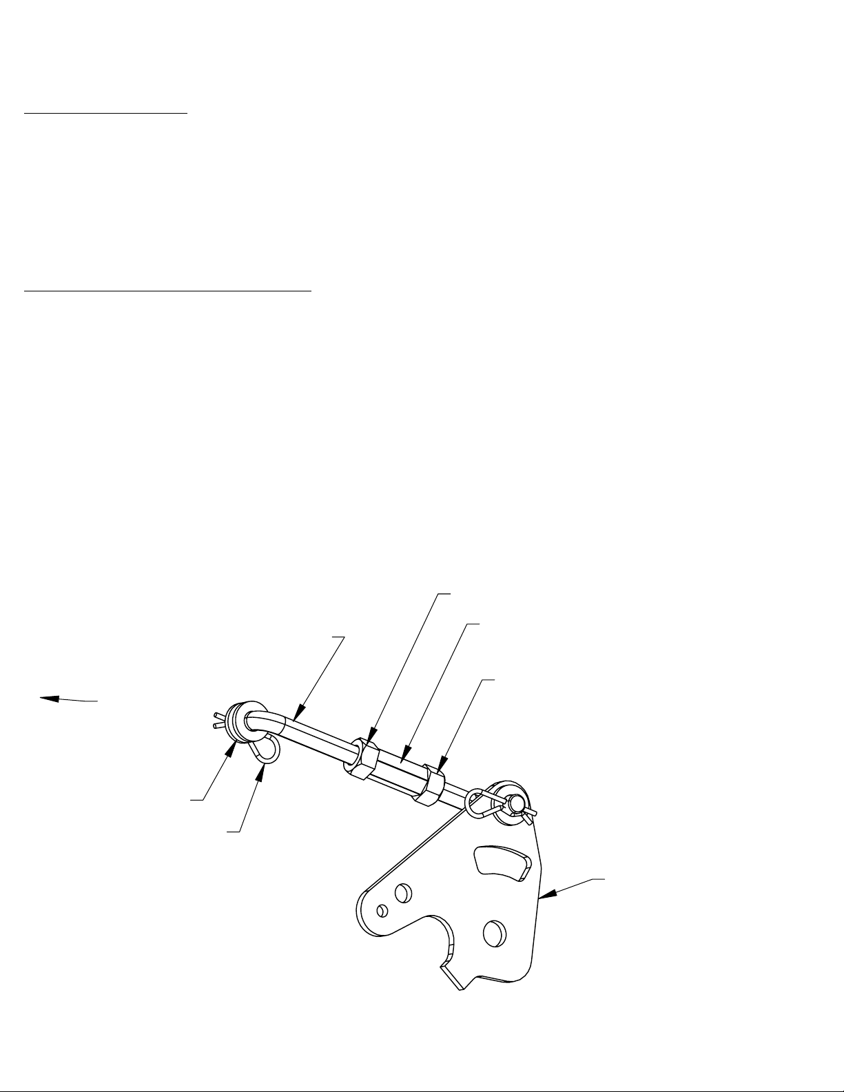
HYDROSTATIC TRANS
CONTROL PLATE
NUT COUPLER
JAM NUT
JAM NUT
HAIR PIN
WASHER
WELDMENT
17469 21 REV. 10-088
SERVICE AND ADJUSTMENTS
Seat Adjustment
:
~The Swisher ZT2452A is equipped with a 6” range sliding seat.
~Release the tension on the seat adjustment lever by pushing the tip of the lever to the left. See features section in
this manual
~Using your own weight, slide the seat to the desired position
~Release the lever
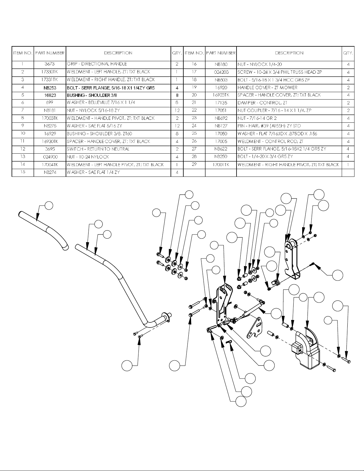
Travel Reduction Adjustment
: (Hand Control Levers)
~To improve the tracking of the Swisher ZT2452A the speeds of the two hydrostatic transmissions must be the same.
If one of the rear wheels needs to be increased or decreased this adjustment can be performed utilizing the control
linkage assembly which is the coltrol rod that connects the handle mechanism to the hydrostatic transmission. There
is one for each transmission.
~If the ZT2452A pulls to the right the left wheel will need to decrease speed and if pulling to the left the right wheel will
need to decrease speed.
~To decrease the speed in one of the rear wheels lengthen the linkage assembly between that side control handle
mechanism and the hydrostatic transmission. Do this be removing the hair pin from the contol handle end and
disengaging the control linkage from the control handle. Loosen one of the jam nuts and by lengthening this control
linkage you can decrease the speed of the hydro. Refer to the exploded view of the control mechanism on the
following pages.
~Be sure the securely tighten the jam nuts against the nut coupler on the control linkage after the desired adjustment
has been made. Reassemble and test. Repeat this process until the mower drives in a straight line.
TO HANDLE
MECHANISM
17469
22
REV. 10-088

17469
23
REV. 10-088
1
2
3
4
4
3
5
6
7
8
9
10
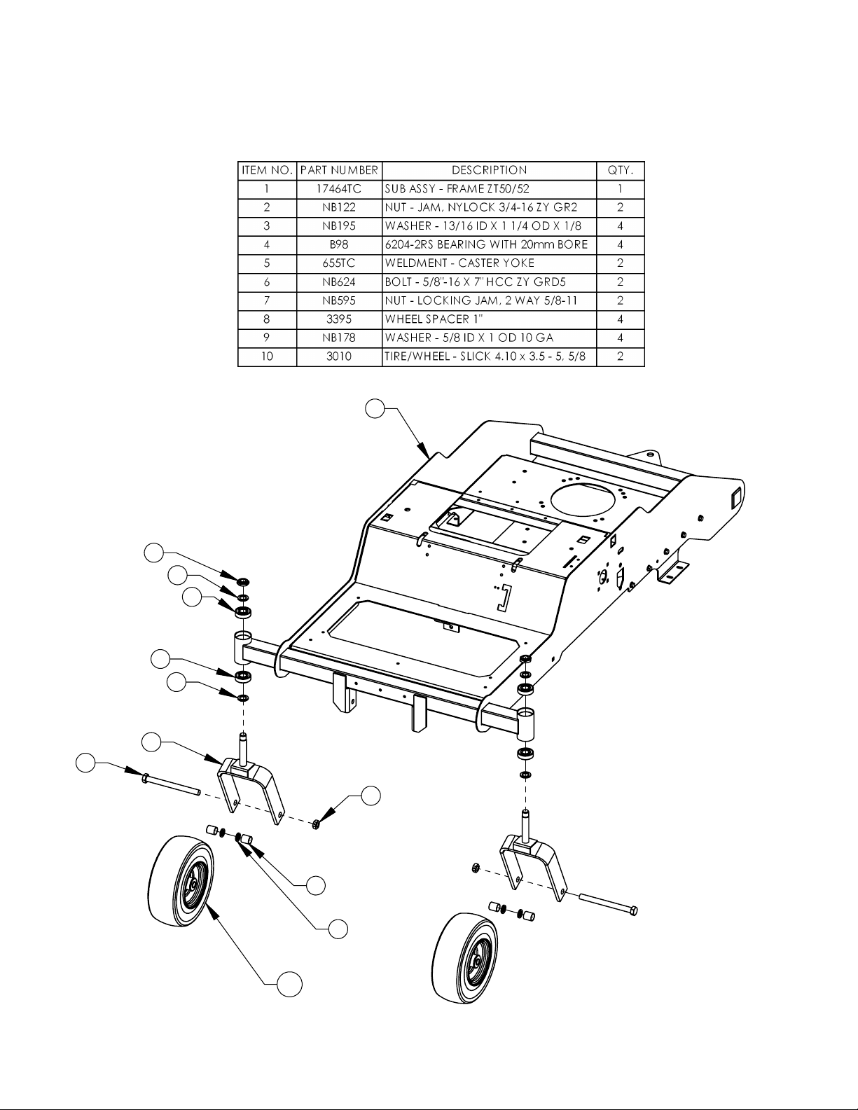
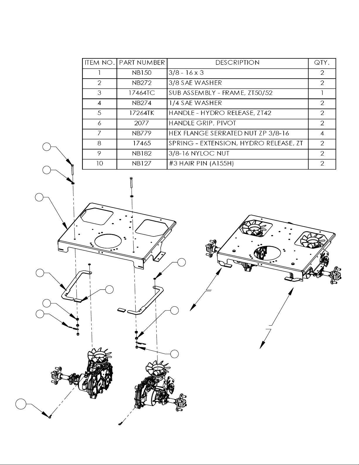
CASTER / FRONT WHEEL
EXPLODED VIEW
17469 24 REV. 10-088
1
2
3
4
5
6
6
7
8
8
9
10
20
18
11
15
14
13
12
17
14
16
11
19
23
22
21
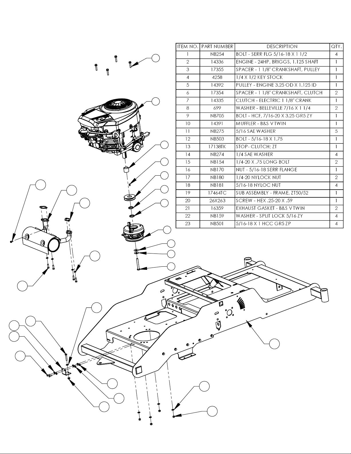
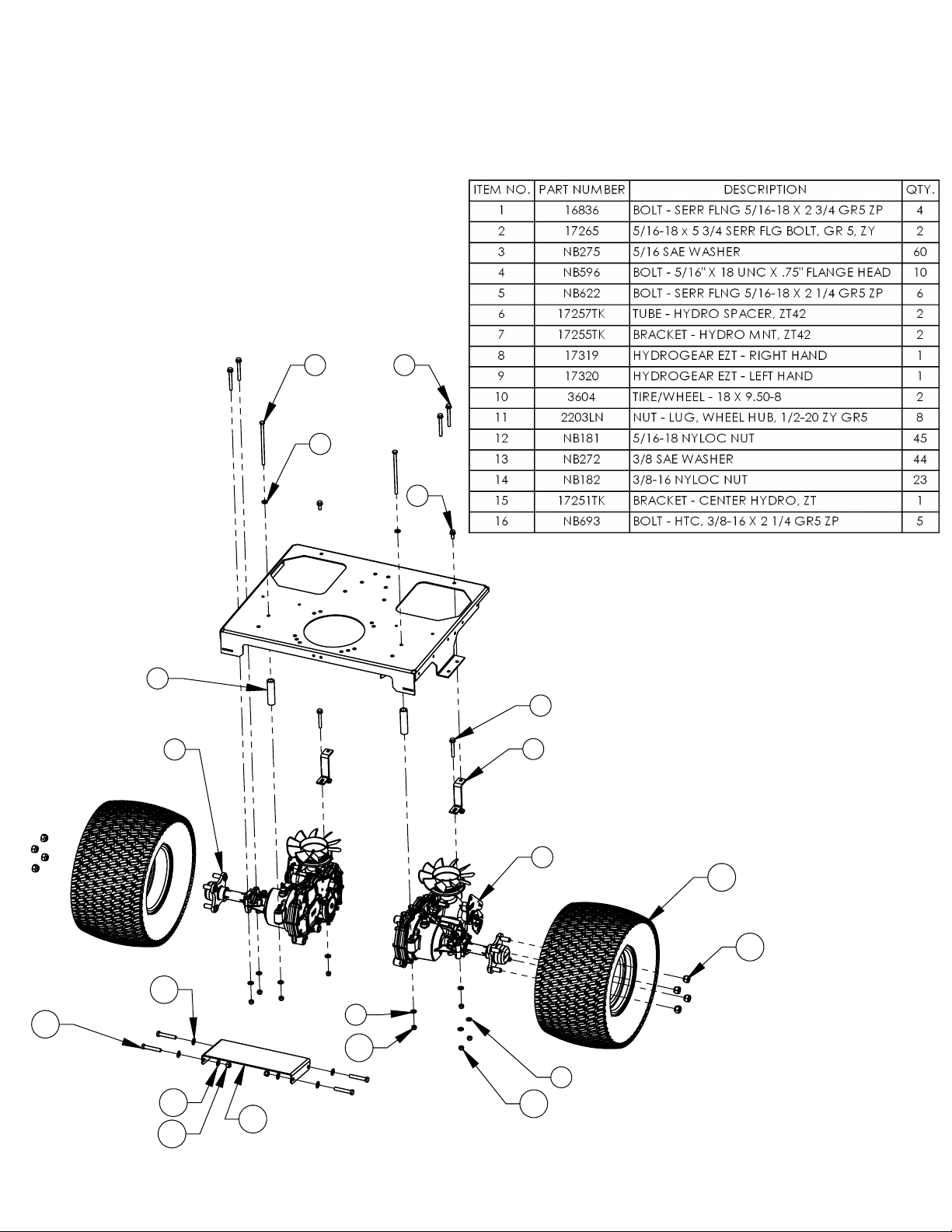
ENGINE / CLUTCH
EXPLODED VIEW
17469 25 REV. 10-088
1
2
3
1
5
6
2
4
2
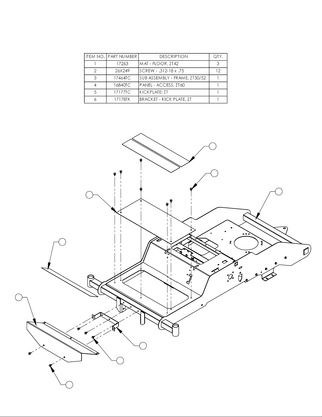
KICK PLATE / ACCESS PANEL
EXPLODED VIEW
17469 26 REV. 10-088
1
2
3
4
5
5
6
7
28 27
16
15
17
14
7
6
10
11
10
9
18
19
9
20
12
13
24
25
26
7
9
8
23
22
21
29
HYDRO CONTROLS
EXPLODED VIEW
- TABLE QTY REFLECTS
RH & LH SIDES
- ONLY THE LH SIDE IS
SHOWN
17469 27 REV. 10-088
1
2
3
6
5
4
7
13
1
12
11
10
9
8
14
GAS TANK / BATTERY
EXPLODED VIEW
17469 28 REV. 10-088
1 2
3
4
5
6
4
11
10
9
8
7
RIGHT
HYDROSTAT
LEFT
HYDROSTAT
12
PARKING BRAKE
EXPLODED VIEW
17469 29 REV. 10-088
1
2
3
4
5
12
13
14
15
16
6
7
8
9
10
11
SEAT/TOOLBOX
EXPLODED VIEW
17469 30 REV. 10-088
1
2
3
5
4
7
8
7
9
10
6
PULL BACK TO
DISENGAGE
HYDRO AND
FREE ROLL
PUSH TO
RE-ENGAGE
HYDRO RELEASE
EXPLODED VIEW
17469 31 REV. 10-088
1
4
2
3
7
5
10
11
8
9
12
3
16
13
13
14
15
12
3
6
HYDROSTATS
EXPLODED VIEW
17469 32 REV. 10-088
2
1
3
5
4
6
9
10
11
2
12
8
7
13
14
15
16
15
17
16
18
21
20
19
27
37
28
22
16
23
26
24
25
46
45
41
39
44
43
42
40
15
16
38
16
2
15
31
51
55
32
33
34
52
53
37
31
30
47
16
49
29
35
36
50
54
56
57
22
22
27
15
2
3
2
58
59
60
48
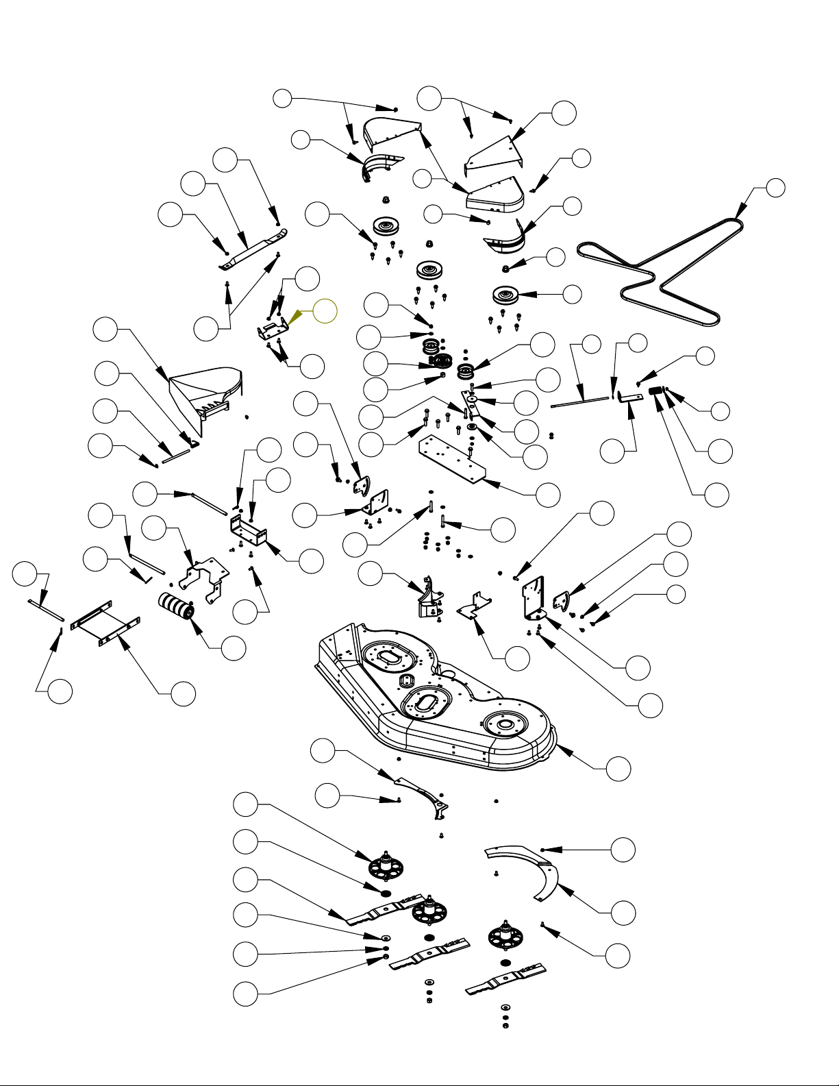
MOW DECK
EXPLODED VIEW
17469 33 REV. 10-088

MOW DECK
EXPLODED VIEW
17469 34 REV. 10-088
1
2
22
23
34
33
32
31
6
7
5
4
3
11
5
4
9
8
22
20
21
4
5
17
16
19
28
29
26
25
24
27
15
30
10
13
12
18
35
36
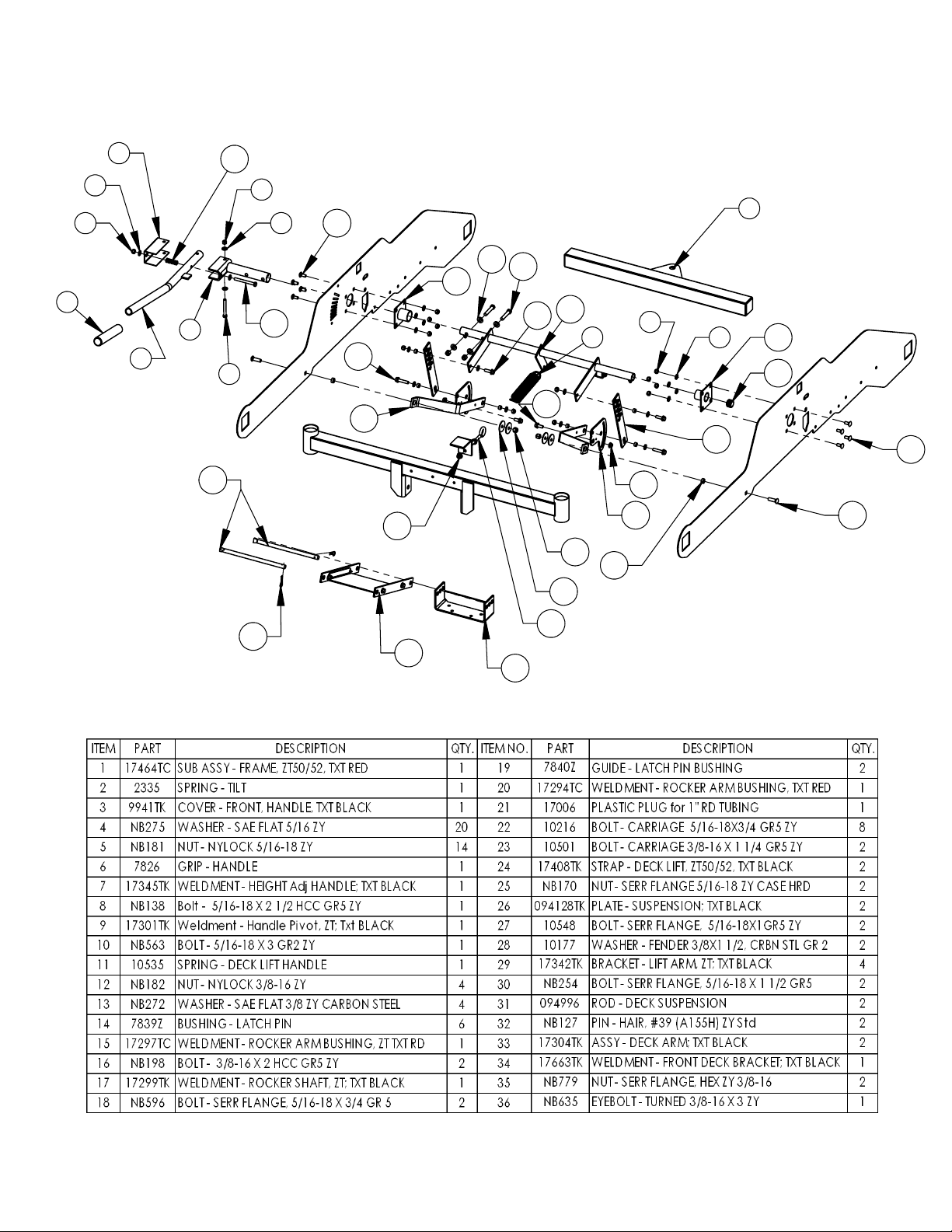
DECK LIFT
EXPLODED VIEW
17469 35 REV. 10-088
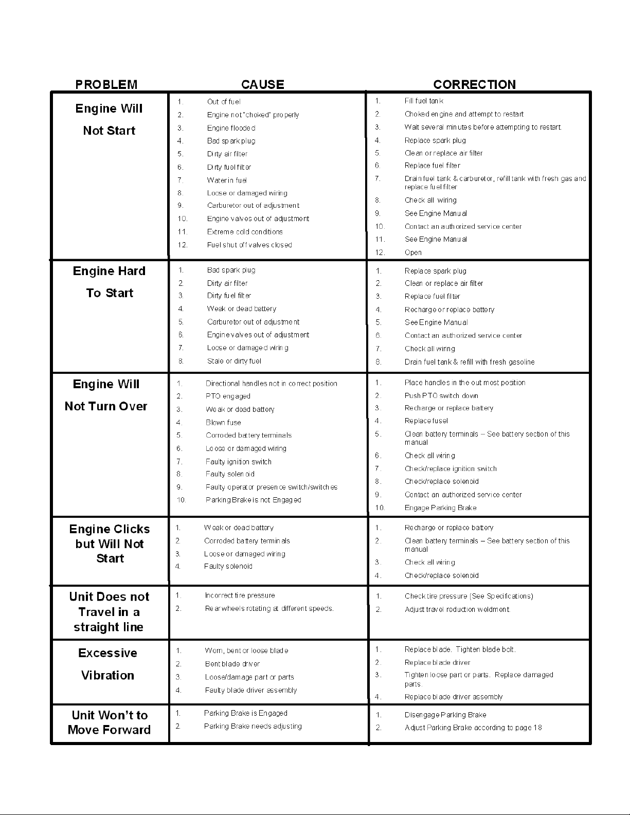
TROUBLESHOOTING
17469 36 REV. 10-088
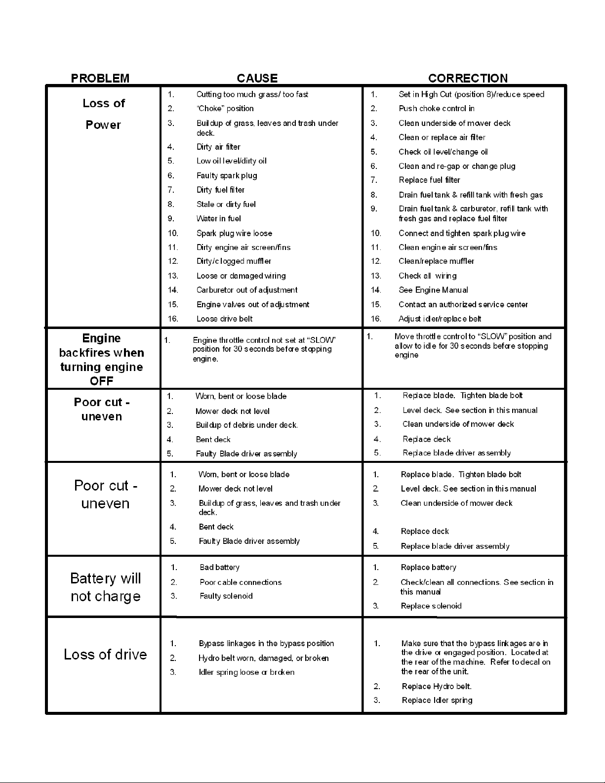
TROUBLESHOOTING
17469 37 REV. 10-088

MOWER IDENTIFICATION
17469 38 REV. 10-088
Mower Identification
Each mower has its own model number. Each
engine has its own model number. The model
number for the mower will be found on a decal
located on the inboard side of the frame side
plate. The model number for the engine will be
found on the top of the blower fan housing.
All mower parts listed herein may be ordered
directly from Swisher or your nearest Swisher
dealer.
All engine parts may be ordered from the
nearest dealer of the engine supplied with your
mower.
Unauthorized Replacement Parts
Use only Swisher replacement parts. The
replacement of any part on this unit with
anything other than Swisher authorized
replacement part may adversely affect
the performance, durability and safety of
this unit and may void the warranty.
Swisher disclaims liability for any claims
or damages, whether warranty, property
damage, personal injury or death arising
out of the use of unauthorized
replacement parts.
WHEN ORDERING PARTS, PLEASE HAVE THE
FOLLOWING INFORMATION AVAILABLE:
Date Purchased ____________________
Purchased From____________________
PRODUCT – ZT2452A
SERIAL NUMBER - _______________
MODEL NUMBER - _______________
ENGINE MODEL NUMBER - _______________
TYPE - _______________
PART NUMBER WITH PAINT CODE__________________
*PART DESCRIPTION______________________________
SWISHER
1602 CORPORATE DRIVE
WARRENSBURG, MO 64093
Swisherinc.com
TELEPHONE - 1-800-222-8183
FAX - 1-660-747-8650

WARRANTY RIGHTS AND OBLIGATIONS
17469 39 REV. 10-088
YOUR WARRANTY RIGHTS AND OBLIGATIONS
: The California Air Resources Board and Swisher, is
pleased to explain the evaporative emission control system (EECS) on your model year 2006 and later Swisher
Product. In California, new Outdoor Power Equipment, must be designed, built and equipped to meet the State’s
stringent anti-smog standards. Swisher must warrant the EECS on your Power Equipment, for the period of
time listed below provided there has been no abuse, neglect, or improper maintenance. For model year 2006 the
EECS on your mower includes the liquid fuel lines, fuel line connectors, and fuel line clamps. Where a warrantable
condition exists, Swisher will repair at no cost to you. Expenses covered under warranty include diagnosis,
parts, and labor.
MANUFACTURER’S WARRANTY COVERAGE
: For a period of two years, any evaporative emission-related part
included in the list of EECS parts for your mower is defective, the part will be repaired or replaced by Swisher.
OWNER’S WARRANTY RESPONSIBILITIES
: As the owner of this Power Equipment, you are responsible for
performance of the required maintenance listed in your owner’s manual. Swisher recommends that you retain
all receipts covering maintenance on your Power Equipment, but Swisher cannot deny warranty solely for the
lack of receipts. As the Power Equipment owner, you should be aware that Swisher, may deny you warranty
coverage if your Power Equipment, or a covered part has failed due to abuse, neglect, or improper maintenance,
unapproved modifications, or the use of parts not made or approved by the equipment manufacturer. You are
responsible for presenting your Power Equipment to an authorized Swisher Service center as soon as the problem
exists. Warranty repairs should be completed in a reasonable amount of time, not to exceed 30 days. If you have a
question regarding your warranty rights and responsibilities, you should contact the Swisher Service
representative at 1-800-222-8183.
WARRANTY COMMENCEMENT DATE
: The warranty period begins on the date the Power Equipment Is purchased.
LENGTH OF COVERAGE
: This warranty shall be for a period of two (2) years from the initial date of purchase.
WHAT IS COVERED
: Warranted parts include the Liquid fuel line, fuel line connectors, and fuel line clamps.
REPAIR OR REPLACEMENT OF PARTS
: Repair or replacement of any evaporative warranted part will be
performed at no charge to the owner at an authorized Swisher Service Center. If you have a question
regarding your warranty rights and responsibilities, you should contact your nearest authorized service center or call
the Swisher Service representative at 1-800-222-8183.
WARRANTY PERIOD
: Any warranted part is not scheduled for replacement as required maintenance, or which is
scheduled only for regular inspection to the effect of “repair or replace as necessary” shall be warranted for two (2)
years. Any warranted part that is scheduled for replacement as required maintenance shall be warranted for the
period of time up to the first scheduled replacement point for that part.
DIAGNOSIS
: The owner shall not be charged for diagnostic labor that leads to the determination that a warranted part
is defective if the diagnostic work is performed at an authorized Swisher Service Center.
CONSEQUENTIAL DAMAGE
: Swisher may be liable for damages to other engine or equipment components
caused by the failure of a warranted part still under warranty.
WHAT IS NOT COVERED
: All failures caused by abuse, neglect, or improper maintenance is not covered.
ADD-ON OR MODIFIED PARTS
: The use of add-on or modified parts may be grounds for disallowing a warranty
claim. Swisher is not liable to cover failures of warranted parts caused by the use of an add-on or modified
part.
HOW TO FILE A CLAIM
: If you have a question regarding your warranty rights and responsibilities, you should
contact your nearest authorized service center or call Swisher Service representative at 1-800-222-8183.

SWISHER HISTORY
Back before electricity came to rural Missouri Max Swisher was producing lawn mowers
from his mother
’
s chicken house. Max never liked to mow grass. He installed a gearbox
on his family
’
s lawn mower creating a self-propelled unit. By tying one end of a rope to
the mower and the other end to a tree in the center of the yard the mower circled the tree,
shortening the rope and guiding the mower in concentric circles. Max enjoyed relaxing
under a shade tree while his invention did all the work.
Max had designed his first self-propelled rotary lawn mower to do his dirty work for him.
Neighbors noticed his new invention and began asking him to make more. Today, 60
years later, Swisher is still producing innovative lawn and garden and ATV/UTV
equipment designed to give us all more
“
relaxing in the shade
”
time.
Swisher products have been featured nationally on television programs such as Regis and
Kathie Lee and seen in publications like
ATV Magazine
,
Country Journal
,
Popular
Mechanics Magazine
and others. In January 2000
Popular Mechanics Magazine
named
Max
’
s zero turning radius riding mower one of the 20th century
’
s top household
inventions.
Swisher offers value and function in its products to meet your grounds maintenance
needs.
17469 40 REV. 10-088
CELEBRATING 65 YEARS OF INNOVATION
SINCE 1945