's m
8}
1-1/2 Horsepower (continuous duty)
2.1 Horsepower (maximum developed)
1200 C.FoM°
3450 R.PoM. (no _oad R.PoM.)
ST COLL
Model No.
152.213371
c_uS
CAUTION:
FOR YOUR OWN SAFETY; Read
and follow all of the Safety and
Operating Instructions before
Operating this Dust CoUlector.
Customer Helpline
1-800-897-7709
PRease have your Model No.
and SedaR No. avaHabUe.
Sears, Roebuck and Co., Hoffman Estates, JL 60179 U.S.A.
Part No. 0R93765 Espa_olpg. 25
SECTmON PAGE
Warranty ..................................................................................... 2
Product Specifications ......................................................................... 2
Safety mnstructions ............................................................................ 3
Grounding mnstructions ......................................................................... 5
Specific Safety mnstructions for Dust Collectors .................................................... 6
Accessories and Attachments ................................................................... 7
Carton Contents .............................................................................. 8
Know Your Dust Collector ..................................................................... 10
AssembJy mnstructions ........................................................................ 11
Operating the Dust Collector ................................................................... 15
Dust Collector in the Shop ..................................................................... 17
Maintenance ................................................................................. 20
Troubleshooting Guide ........................................................................ 20
Parts List ................................................................................... 21
Service mnformation ........................................................................... 48
ONE-YEAR FULL WARRANTY ON CRAFTSMAN PROFESSIONAL TOOL
if this Craftsman tool fails due to a defect in material or workmanship within one year from the date of purchase,
CALL 1-800-4-MYoHOME@ TO ARRANGE FOR FREE REPAIR,
This warranty applies only while this tool is in the United States,
This warranty gives you specific legal rights, and you may also have other rights, which vary, from state to state,
Sears, Roebuck and Co,, Dept, 817WA, Hoffman Estates, IL 60179 06/05
induction Motor
Continuous duty HP
Maximum developed HP
Amps
Volts
Hertz
RPM
Standard Bag Top
Standard Bag Bottom
Collection Hose
Maximum C, F, M,
Maximum static pressure
in inches of water
1-1/2
2,1
12/6
120/240
6O
3450 R,P,M,
(no load R,P,M,)
30 micron
30 micron
4-inch Flexible Hose
1200
12
To avoid electrical shock to yourself and damage to the
Dust Collector, use proper circuit protection, Do not
expose to rain, or use in a damp environment,
The Dust Collector is factory wired for 120V, 60 Hz,
operation, Connect to a 120V, 15 amp branch circuit
and use a 15 amp time delay fuse or circuit breaker,
The electrical circuit cannot have any wire size less
than #14, To avoid shock or fire, replace power cord
immediately if it is damaged in any way,
Filter Bag capacity
Collection Bag capacity
6 cubic feet
6 cubic feet
GENERAL SAFETY iNSTRUCTiONS
Operating a Dust Collector can be dangerous if safety
and common sense are ignored, The operator must be
familiar with the operation of the took Read this manual
to understand this Dust Collector, DO NOT operate this
Dust Collector if you do not fully understand the limita-
tions of this tool, DO NOT modify this Dust Collector in
any way, REMEMBER: Your personal safety is your
responsibility,
BEFORE USUNG THE DUST COLLECTOR
9,
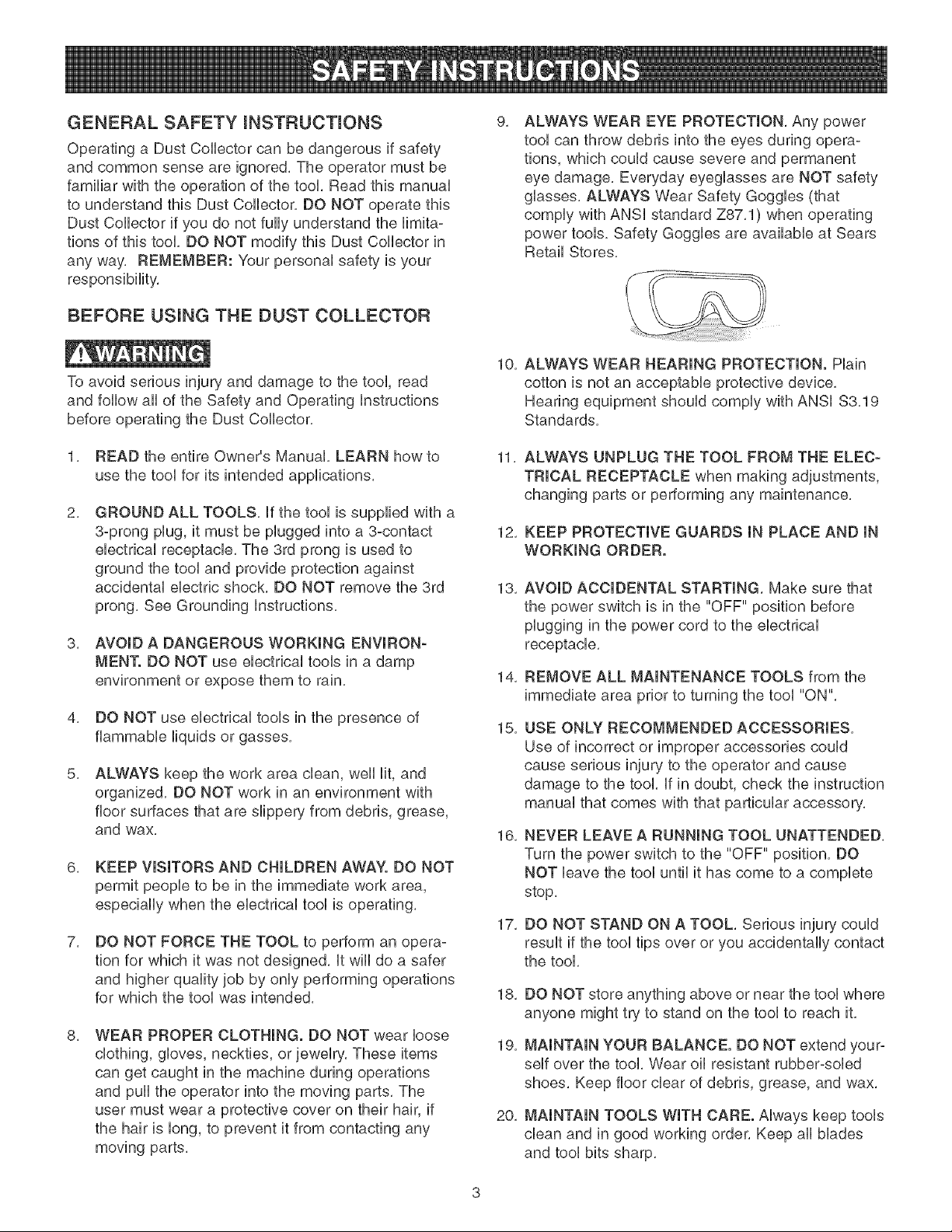
ALWAYS WEAR EYE PROTECTmON, Any power
tool can throw debris into the eyes during opera-
tions, which could cause severe and permanent
eye damage, Everyday eyeglasses are NOT safety
glasses, ALWAYS Wear Safety Goggles (that
comply with ANSi standard Z87,1) when operating
power tools. Safety Goggles are available at Sears
Retail Stores,
To avoid serious injury and damage to the tool, read
and follow all of the Safety and Operating instructions
before operating the Dust Collector,
1, READ the entire Owner's Manual, LEARN how to
use the tool for its intended applications,
2,
GROUND ALL TOOLS, if the tool is supplied with a
3-prong plug, it must be plugged into a 3-contact
electrical receptacle, The 3rd prong is used to
ground the tool and provide protection against
accidental electric shocL DO NOT remove the 3rd
prong, See Grounding instructions,
3, AVOID A DANGEROUS WORKmNG ENVmRON-
MEN'[. DO NOT use electrical tools in a damp
environment or expose them to rain.
4, DO NOT use electrical tools in the presence of
flammable liquids or gasses,
5,
ALWAYS keep the work area clean, well lit, and
organized, DO NOT work in an environment with
floor surfaces that are slippery from debris, grease,
and wax,
6, KEEP VmSmTORSAND CHmLDREN AWAY. DO NOT
permit people to be in the immediate work area,
especially when the electrical tool is operating,
7,
DO NOT FORCE THE TOOL to perform an opera-
tion for which it was not designed, it wiii do a safer
and higher quality job by only performing operations
for which the tool was intende&
8, WEAR PROPER CLOTHING. DO NOT wear loose
clothing, gloves, neckties, or jewelry, These items
can get caught in the machine during operations
and pull the operator into the moving parts, The
user must wear a protective cover on their hair, if
the hair is long, to prevent it from contacting any
moving parts,
10,
11,
12,
13,
14,
15,
16,
17,
18,
19,
20,
ALWAYS WEAR HEARING PROTECTION. Plain
cotton is not an acceptable protective device,
Hearing equipment should comply with ANSi $3,19
Standards,
ALWAYS UNPLUG THE TOOL FROM THE ELEC-
TRICAL RECEPTACLE when making adjustments,
changing parts or performing any maintenance,
KEEP PROTECTIVE GUARDS IN PLACE AND IN
WORKING ORDER.
AVOID ACCIDENTAL STARTING, Make sure that
the power switch is in the "OFF" position before
plugging in the power cord to the electrical
receptacle,
REMOVE ALL MAINTENANCE TOOLS from the
immediate area prior to turning the tool "ON",
USE ONLY RECOMMENDED ACCESSORIES,
Use of incorrect or improper accessories could
cause serious injury to the operator and cause
damage to the took if in doubt, check the instruction
manual that comes with that particular accessory,
NEVER LEAVE A RUNNING TOOL UNATTENDED,
Turn the power switch to the "OFF" position, DO
NOT leave the tool until it has come to a complete
stop,
DO NOT STAND ON A TOOL. Serious injury could
result if the tool tips over or you accidentally contact
the tool.
DO NOT store anything above or near the tool where
anyone might try to stand on the tool to reach it.
MAINTAIN YOUR BALANCE. DO NOT extend your-
self over the took Wear oil resistant rubber-soled
shoes, Keep floor clear of debris, grease, and wax,
MAINTAIN TOOLS WITH CARE. Always keep tools
clean and in good working order, Keep all blades
and tool bits sharp,
21,EACHANDEVERYTmME,CHECK FOR DAM-
AGED PARTS PRmOR TO USmNGTHE TOOL,
Carefully check all guards to see that they operate
properly, are not damaged, and perform their
intended functions, Check for alignment, binding or
breaMng of moving parts, A guard or other part that
is damaged should be immediately repaired or
replaced,
22, CHILDPROOF THE WORKSHOP AREA by remov-
ing switch keys, unplugging tools from the electrical
receptacles, and using padlocks,
23, DO NOT OPERATE TOOL IF UNDER THE INFLU-
ENCE OF DRUGS OR ALCOHOL,
24, SECURE ALL WORK, When it is possible, use
clamps or jigs to secure the work-piece, This is
safer than attempting to hold the work-piece with
your hands,
25, STAY ALERT, WATCH WHAT YOU ARE DOING,
AND USE COMMON SENSE WHEN OPERATING
A POWER TOOL. DO NOT USE A TOOL WHILE
TIRED OR UNDER THE INFLUENCE OF DRUGS,
ALCOHOL, OR MEDICATION, A moment of
inattention while operating power tools may result
in serious personal injury,
26, ALWAYS WEAR A DUST MASK TO PREVENT
INHALING DANGEROUS DUST OR AIRBORNE
PARTICLES, including wood dust, crystalline silica
dust and asbestos dust, Direct particles away
from face and body, Always operate tool in well
ventilated area and provide for proper dust removal,
Use dust collection system whenever possible,
Exposure to the dust may cause serious and
permanent respiratory or other injury, including
silicosis (a serious lung disease), cancer, and
death, Avoid breating the dust, and avoid prolonged
contact with dust, Allowing dust to get into your
mouth or eyes, or lay on your skin may promote
absorption of harmful material, Always use properly
fitting NIOSH/OSHA approved respiratory protection
appropriate for the dust exposure, and wash
exposed areas with soap and water,
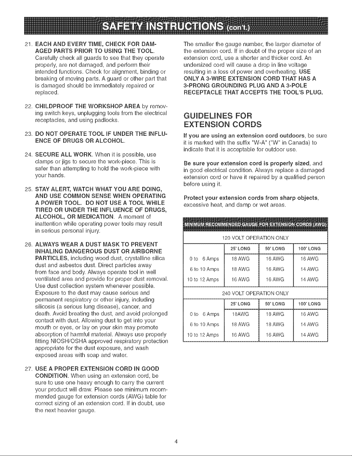
27, USE A PROPER EXTENSION CORD IN GOOD
CONDITION, When using an extension cord, be
sure to use one heavy enough to carry the current
your product will draw, Please see minimum recom-
mended gauge for extension cords (AWG) table for
correct sizing of an extension cord, if in doubt, use
the next heavier gauge,
The smaller the gauge number, the larger diameter of
the extension cord, if in doubt of the proper size of an
extension cord, use a shorter and thicker cord, An
undersized cord will cause a drop in line voltage
resulting in a loss of power and overheating, USE
ONLY A 3-WIRE EXTENSION CORD THAT HAS A
3-PRONG GROUNDING PLUG AND A 3-POLE
RECEPTACLE THAT ACCEPTS THE TOOL'S PLUG.
GUJDEUNES FOR
EXTENSION CORDS
If you are using an extension cord outdoors, be sure
it is marked with the suffix "W-A" ("W" in Canada) to
indicate that it is acceptable for outdoor use,
Be sure your extension cord is properly sized, and
in good electrical condition, Always replace a damaged
extension cord or have it repaired by a qualified person
before using it,
Protect your extension cords from sharp objects,
excessive heat, and damp or wet areas,
0 to 6 Amps
6 to 10 Amps
10 to 12 Amps
0 to 6Amps
6 to 10 Amps
10 to 12 Amps
120 VOLT OPERATION ONLY
25' LONG
18 AWG
18 AWG
16 AWG
50' LONG
16 AWG
16 AWG
16 AWG
240 VOLT OPERATION ONLY
25' LONG
18AWG
18 AWG
16 AWG
50' LONG
18 AWG
18 AWG
16 AWG
100' LONG
16 AWG
14 AWG
14 AWG
100' LONG
16 AWG
14 AWG
14 AWG
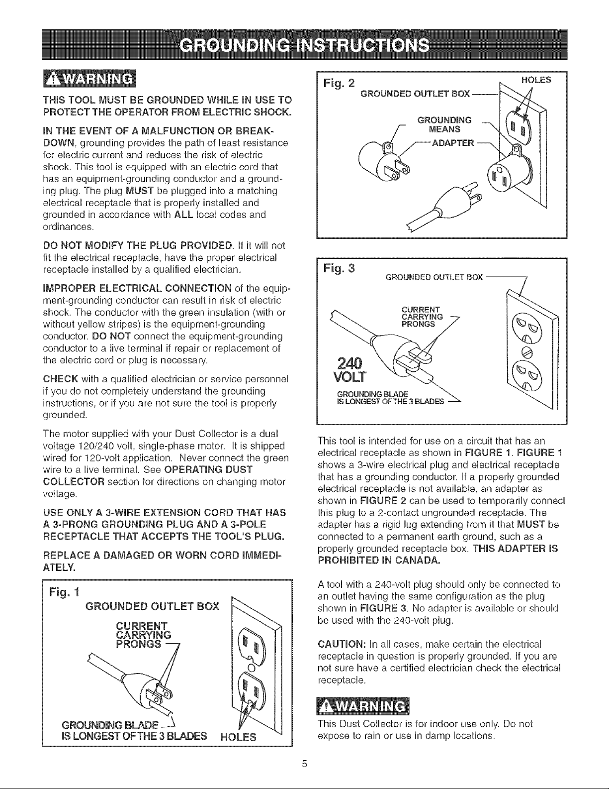
THIS TOOL MUST BE GROUNDED WHILE iN USE TO
PROTECT THE OPERATOR FROM ELECTRIC SHOCK.
iN THE EVENT OF A MALFUNCTION OR BREAK-
DOWN, grounding provides the path of bast resistance
for eUectriccurrent and reduces the risk of eUectric
shock, This tooUis equipped with an eUectric cord that
has an equbment-grounding conductor and a ground-
ing pUug,The pUugMUST be pUugged into a matching
eUectrbaUreceptacb that is properUy installed and
grounded in accordance with ALL bcaU codes and
ordinances,
DO NOT MODIFY THE PLUG PROVIDED, If it will not
fit the electrical receptacb, have the proper electrbal
receptacb installed by a qualified electrician,
IMPROPER ELECTRICAL CONNECTION of the equip-
ment-grounding conductor can result in risk of electric
shock, The conductor with the green insulation (with or
without yellow stripes) is the equipment-grounding
conductor, DO NOT connect the equipment-grounding
conductor to a live terminal if repair or replacement of
the electric cord or plug is necessary,
CHECK with a qualified electrician or ser4ce personnel
if you do not completely understand the grounding
instructions, or if you are not sure the tool is properly
grounded,
The motor supplied with your Dust Collector is a dual
voltage 120/240 volt, singb-phase motor, It is shipped
wired for 120-volt application, Never connect the green
wire to a live terminal, See OPERATING DUST
COLLECTOR section for directions on changing motor
voltage,
USE ONLY A 3-WIRE EXTENSION CORD THAT HAS
A 3-PRONG GROUNDING PLUG AND A 3-POLE
RECEPTACLE THAT ACCEPTS THE TOOL'S PLUG.
REPLACE A DAMAGED OR WORN CORD IMMEDI-
ATELY.
Fig. 1
GROUNDED OUTLET BOX
CURRENT
CARRYING
GROI;3_
USLONGEST OFTHE 3 BLADES
HOLES
Fig. 2
GROUNDED OUTLET BOX--
GROUND|NG
MEANS
HOLES
Fig. 3
GROUNDED OUTLET BOX
CURRENT
CARRYING
PRONGS
24O
VOLT
GROUNDING BLADE
BLONGESTOFTNE3BLADES
O
This tool is intended for use on a circuit that has an
electrical receptacle as shown in FIGURE !, FIGURE 1
shows a 3-wire electrical plug and electrical receptacle
that has a grounding conductor, If a properly grounded
electrical receptacle is not available, an adapter as
shown in FIGURE 2 can be used to temporarily connect
this plug to a 2-contact ungrounded receptacle, The
adapter has a rigid lug extending from it that MUST be
connected to a permanent earth ground, such as a
properly grounded receptacle box, THIS ADAPTER IS
PROHIBITED IN CANADA.
A tool with a 240-volt plug should only be connected to
an outlet having the same configuration as the plug
shown in FIGURE 3, No adapter is available or should
be used with the 240°volt plug,
CAUTION: in all cases, make certain the electrical
receptacle in question is properly grounded, if you are
not sure have a certified electrician check the electrical
receptacle,
This Dust Collector is for indoor use only, Do not
expose to rain or use in damp locations,

SPECiFiC SAFETY iNSTRUCTiONS
FOR DUST COLLECTORS
The operation of any Dust Colbctor can result in debris
being thrown into your eyes, which can result in severe
eye damage, ALWAYS Wear Safety Goggbs (that com-
ply with ANSi standard Z87,1) when operating the Dust
Collector, Safety Goggbs are availabb at Sears Retail
Stores, Keep your thumbs and fingers away from intake
ports,
Basic precautions should always be followed when using
your dust collector, To reduce the risk of injury, electrical
shock or fire, comply with the safety rubs listed below:
1, READ and understand the instruction manual
before operating the dust collector,
2, DO NOT OPERATE THIS MACHINE until it is
assembled and installed according to the instruc-
tions,
3, OBTAIN ADVICE FROM YOUR SUPERVISOR,
instructor, or another qualified person if you are not
familiar with the operation of this machine,
4,
DO NOT leave the dust collector plugged into the
electrical outlet, Unplug dust collector from the out-
let when not in use and before servicing, changing
bags, unclogging and cleaning,
5, ALWAYS turn the power switch "OFF" before
unplugging the dust collector,
6, TO REDUCE THE RISK OF ELECTRICAL
SHOCK, do not use outdoors, Do not expose to
rain, Store indoors, Use only for dry pick up,
7,
FOLLOW all electrical and safety codes, including
the National Electric Code (NEC) and the Occu-
pational Safety and Health Regulations (OSHA), All
electrical connections and wiring should be made
by qualified personnel only,
8, DO NOT handle the plug or dust collector with wet
hands,
9,
DO NOT use the dust collector to pick up flam-
mable or combustible liquids, such as gasoline,
NEVER use the dust collector near any flammable
or combustible liquids,
10, USE the dust collector to pick up wood materials
only, DO NOT use the dust collector to pick up
metal shavings, metal dust, or parts,
11, NEVER use the dust collector to dissipate fumes or
smoke, NEVER pick up anything that is burning or
smoking, such as cigarettes, matches or hot ashes,
12,
13,
14,
15,
16,
17,
18,
19,
20,
21,
22,
23,
24,
USE only as described in this manual, USE acces-
sories only recommended by Sears,
DO NOT pull the dust collector by the power cord,
NEVER allow the power cord to come in contact
with sharp edges, hot surfaces, oil or grease,
DO NOT unplug the dust collector by pulling on the
power cord, ALWAYS grasp the plug, not the cord,
REPLACE a damaged cord immediately, DO NOT
use a damaged cord or plug, if the dust collector is
not operating properly, or has been damaged, left
outdoors or has been in contact with water, return it
to a Sears Service Center,
DO NOT use the dust collector as a toy, DO NOT
use near or around children,
DO NOT insert fingers or foreign objects into the
dust intake port, Keep hair, loose clothing, fingers,
and all body parts away from openings and moving
parts of the dust collector,
DO NOT use the dust collector without the dust
collection bag in place and properly secured,
ALWAYS use safety gates or caps to cover dust
ports when the dust collector is not in use or
mounted to a supporting surface for storage,
PERIODICALLY INSPECT dust bag for any cuts,
rips or tears, NEVER operate the dust collector with
a damaged bag or vacuum hose,
The dust collector is designed for home use or light
commercial duty ONLY,
CONNECT dust collector to a properly grounded
outlet only, See grounding instructions,
ADDITIONAL INFORMATION regarding the safe
and proper operation of this product is available
from the National Safety Council, 1121 Spring Lake
Drive, Itasca, IL 60143-3201 in the Accident Pre-
vention Manual for Industrial Operation and also in
the Safety Data Sheets provided by the NSC,
Please also refer to the American National Stand-
ards institute ANSi 01,1 Safety Requirements for
Woodworking Machinery and the U,S, Department
of Labor OSHA 1910,213 Regulations,
SAVE THESE INSTRUCTIONS, Refer to them
frequently and use them to instruct other users,
AVAILABLE ACCESSORIES
Visit your Sears Hardware Department or see the Sears
Power and Hand Tool CataUog for the following acces-
sories,
ITEM
30 micron filter bag (top)
5 micron filter bag (top)
PUasticcollection bag (bottom)
4" Diameter x 10' fiexiMe hose
4" Diameter x 25' fiexiMe hose
Various accessory fittings
STOCK NUMBER
21379
21380
21381
21372
21373
See cataUog or store
Sears may recommend other accessories not Hsted in
this manual
See your nearest Sears Hardware Department or Sears
Power and Hand Tool CataUog for other accessories,
Do not use any accessory unUess you have compUeteUy
read the Owner's ManuaUfor that accessory,
Use onUyaccessories recommended for this Dust
Collector, Using other accessories may cause serious
injury and cause damage to the Dust Collector,

UNPACKING AN{) CHECKING
CONTENTS (Figure 4 and Figure 5)
This Dust Collector will require a minimal amount of
assembly,
Remove all of the parts from the shipping box and lay
them on a dean work surface, Compare the items to
Figure 4 and Figure 5, verify that all items are account°
ed for before discarding the shipping box,
Fig. 4
F
if any parts are missing, do not attempt to plug in the
power cord and turn "ON" the Dust Collector, The Dust
Collector can only be turned "ON" after all the parts
have been obtained and installed correctly,
A
D
o
o
C
o
o
A, Blower and motor Assembly
B, 4°inch Hose Clamp
C, 4°inch Diameter Flexible Hose
D, intake Port
E, Base
F, intake Port Caps (2)
G, Drum
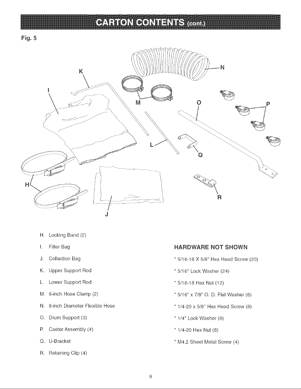
Fig. 5
K
L
O p
R
J
H, Locking Band (2)
L FHter Bag
J, Collection Bag
K, Upper Support Rod
L, Lower Support Rod
M, 6-inch Hose CUamp (2)
N, 6-inch Diameter FUexibUeHose
O, Drum Support (3)
P, Caster AssemMy (4)
Q, U-Bracket
R, Retaining CHp (4)
HARDWARE NOT SHOWN
* 5/16-18 X 5/8" Hex Head Screw (20)
* 5/16" Lock Washer (24)
* 5/16-18 Hex Nut (12)
* 5/16" x 7/8" O, D, FUatWasher (6)
* 1/4-20 x 5/8" Hex Head Screw (8)
* 1/4" Lock Washer (8)
* 1/4-20 Hex Nut (8)
* M4,2 Sheet MetaUScrew (4)
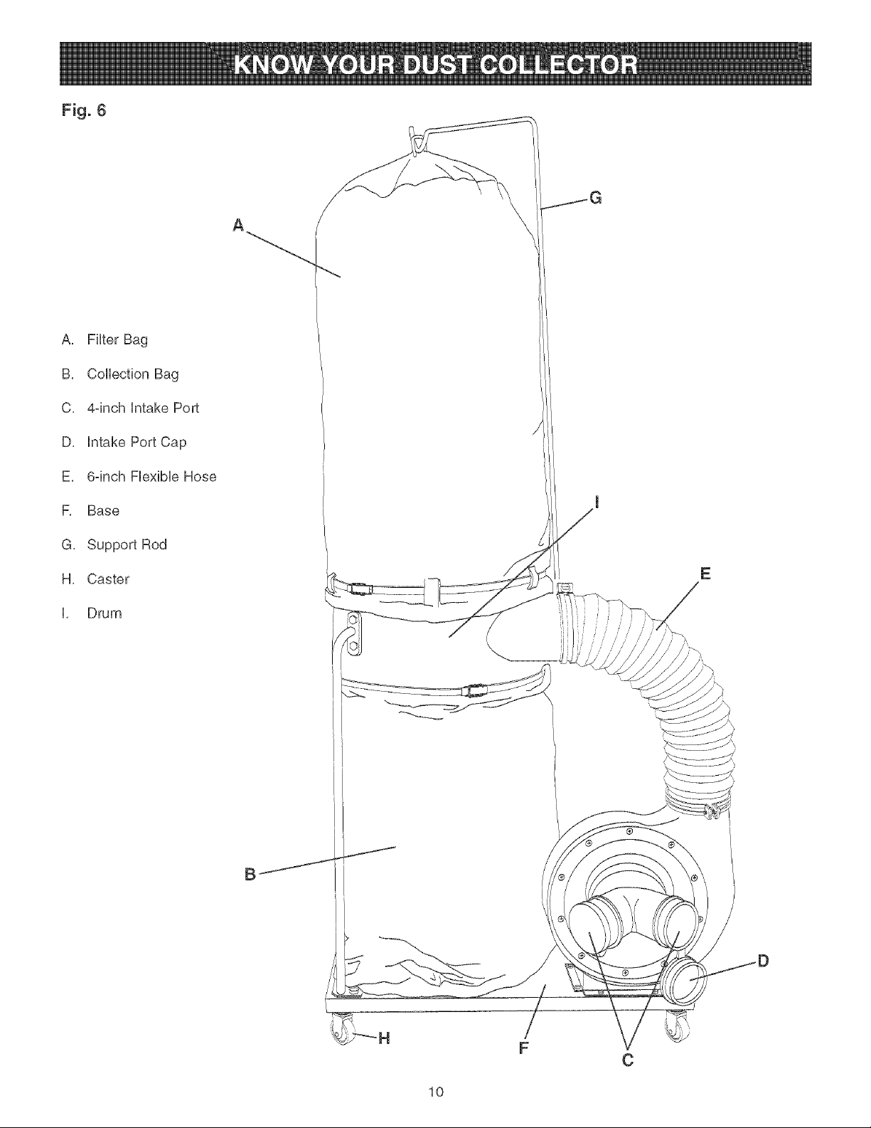
Fig. 6
A, FHter Bag
B, CoHHectionBag
C, 44nch Hntake Port
D, Hntake Port Cap
E, 64nch FHexibHeHose
F, Base
G, Support Rod
H, Caster
[, Drum
A
E
F
C
10
2,
2,
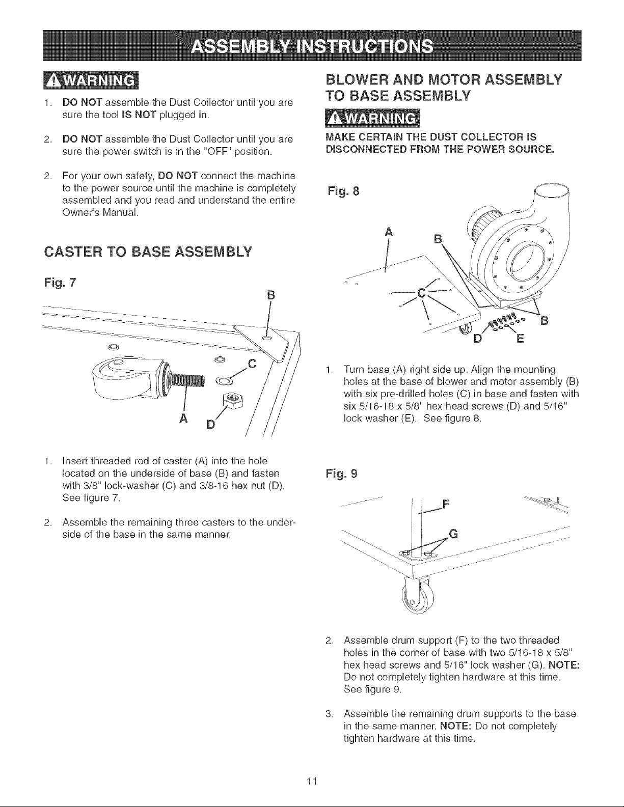
DO NOT assemble the Dust Collector until you are
sure the tool IS NOT plugged in,
DO NOT assemble the Dust Collector until you are
sure the power switch is in the "OFF" position,
For your own safety, DO NOT connect the machine
to the power source until the machine is completely
assembled and you read and understand the entire
Owner's Manual,
CASTER TO BASE ASSEMBLY
Fig. 7
B
A
BLOWER AND MOTOR ASSEMBLY
TO BASE ASSEMBLY
MAKE CERTAIN THE DUST COLLECTOR iS
DISCONNECTED FROM THE POWER SOURCE.
A
B
B
D E
1,
Turn base (A) right side up, Align the mounting
hobs at the base of blower and motor assembly (B)
with six pre-drilled hobs (C) in base and fasten with
six 5/16=18 x 5/8" hex head screws (D) and 5/16"
lock washer (E), See figure 8,
2,
insert threaded rod of caster (A) into the hob
located on the underside of base (B) and fasten
with 3/8" lock=washer (C) and 3/8-16 hex nut (D),
See figure 7,
Assemble the remaining three casters to the under-
side of the base in the same manner,
Fig. 9
G
2,
3,
Assemble drum support (F) to the two threaded
hobs in the corner of base with two 5/16=18 x 5/8"
hex head screws and 5/16" lock washer (G), NOTE:
Do not completely tighten hardware at this time,
See figure 9,
Assemble the remaining drum supports to the base
in the same manner, NOTE: Do not completely
tighten hardware at this time,
11
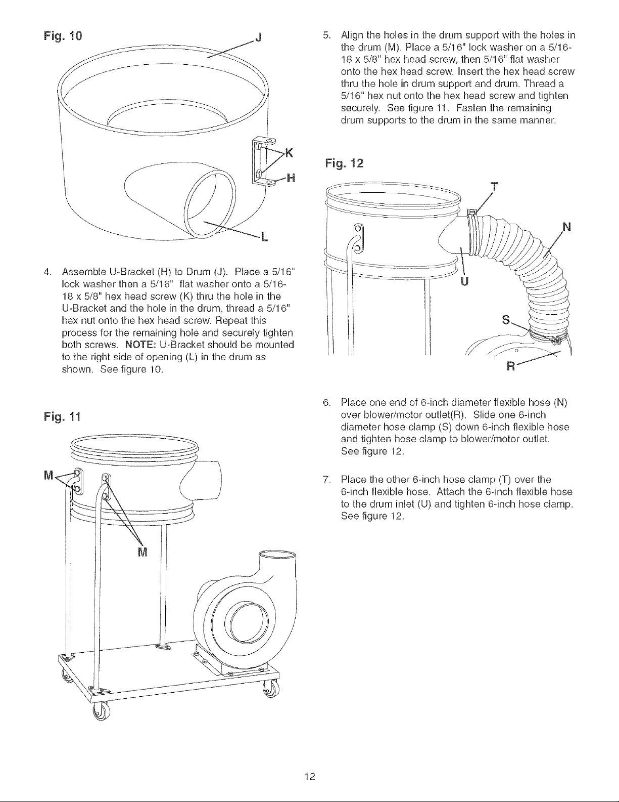
5,
Align the hobs in the drum support with the hobs in
the drum (M), Place a 5/16" lock washer on a 5/16-
18 x 5/8" hex head screw, then 5/16" fiat washer
onto the hex head screw, insert the hex head screw
thru the hob in drum support and drum, Thread a
5/16" hex nut onto the hex head screw and tighten
securely, See figure 11, Fasten the remaining
drum supports to the drum in the same manner,
Fig. 12
T
4,
Assemble U-Bracket (H) to Drum (J), Place a 5/16"
lock washer then a 5/16" fiat washer onto a 5/16-
18 x 5/8" hex head screw (K) thru the hob in the
U-Bracket and the hob in the drum, thread a 5/16"
hex nut onto the hex head screw, Repeat this
process for the remaining hob and securely tighten
both screws, NOTE: U-Bracket should be mounted
to the right side of opening (L) in the drum as
shown, See figure 10,
Fig. 11
ME
8,
7,
Place one end of 6°inch diameter flexible hose (N)
over blower/motor outlet(R), Slide one 6°inch
diameter hose clamp (S) down 6°inch flexible hose
and tighten hose clamp to blower/motor outlet,
See figure 12,
Place the other 6-inch hose clamp (T) over the
6-inch flexible hose, Attach the 6-inch flexible hose
to the drum inlet (U) and tighten 6-inch hose clamp,
See figure 12,
12
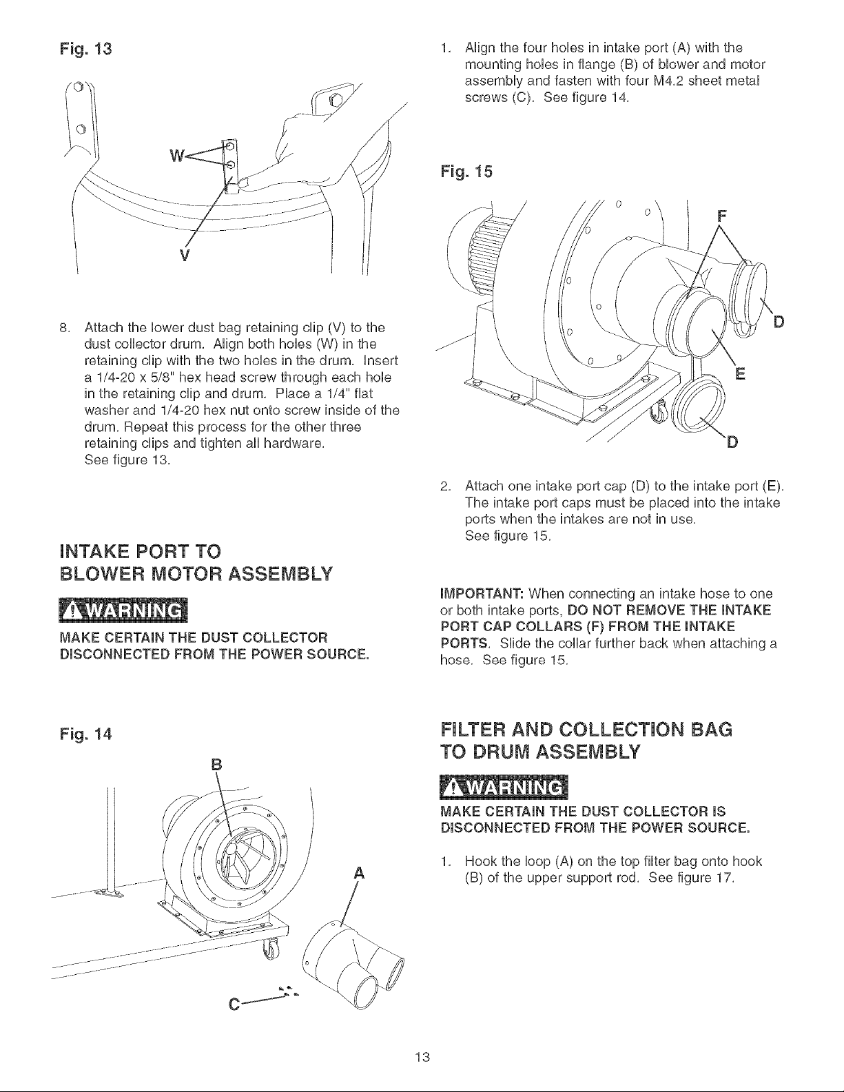
Fig. 13
V
/
/
1,
Align the four hobs in intake port (A) with the
mounting hobs in flange (B) of blower and motor
assembly and fasten with four M4,2 sheet metal
screws (C), See figure 14,
Fig. 15
0
0
8,
Attach the lower dust bag retaining clip (V) to the
dust collector drum, Align both hobs (W) in the
retaining clip with the two hobs in the drum, insert
a 1/4-20 x 5/8" hex head screw through each hob
in the retaining clip and drum, Place a 1/4" fiat
washer and 1/4-20 hex nut onto screw inside of the
drum, Repeat this process for the other three
retaining clips and tighten all hardware,
See figure 13,
iNTAKE PORT TO
BLOWER MOTOR ASSEMBLY
MAKE CERTAIN THE DUST COLLECTOR
DISCONNECTED FROM THE POWER SOURCE.
E
D
2,
Attach one intake port cap (D) to the intake port (E),
The intake port caps must be placed into the intake
ports when the intakes are not in use,
See figure 15,
IMPORTANT: When connecting an intake hose to one
or both intake ports, DO NOT REMOVE THE INTAKE
PORT CAP COLLARS (F} FROM THE INTAKE
PORTS, Slide the collar further back when attaching a
hose, See figure 15,
Fig. 14
B
NLTER AND COLLECTION BAG
TO DRUM ASSEMBLY
MAKE CERTAIN THE DUST COLLECTOR IS
DISCONNECTED FROM THE POWER SOURCE.
A
1, Hook the loop (A) on the top filter bag onto hook
(B) of the upper support rod, See figure 17,
13
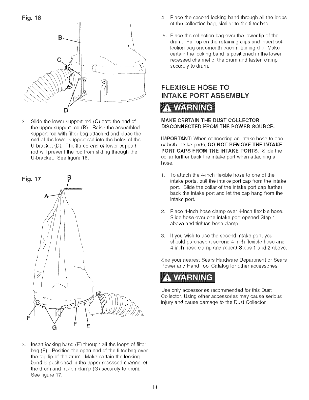
Fig. 16
\
4, Place the second locking band through all the loops
of the collection bag, similar to the filter bag,
5,
Place the collection bag over the lower lip of the
drum, Pull up on the retaining clips and insert cop
lection bag underneath each retaining clip, Make
certain the locking band is positioned in the lower
recessed channel of the drum and fasten clamp
securely to drum,
2,
D
Slide the lower support rod (C) onto the end of
the upper support rod (B), Raise the assembled
support rod with filter bag attached and place the
end of the lower support rod into the hobs of the
U=bracket (D), The flared end of lower support
rod will prevent the rod from sliding through the
U=bracket, See figure 16,
FLEXIBLE HOSE TO
iNTAKE PORT ASSEMBLY
MAKE CERTAIN THE DUST COLLECTOR
DISCONNECTED FROM THE POWER SOURCE.
IMPORTANT: When connecting an intake hose to one
or both intake ports, DO NOT REMOVE THE INTAKE
PORT CAPS FROM THE INTAKE PORTS, Slide the
collar further back the intake port when attaching a
hose,
1, To attach the 4-inch flexible hose to one of the
intake ports, pull the intake port cap from the intake
port, Slide the collar of the intake port cap further
back the intake port and let the cap hang from the
intake port,
2, Place 4=inch hose clamp over 4=inch flexible hose,
Slide hose over one intake port opened Step 1
above and tighten hose clamp,
3, if you wish to use the second intake port, you
should purchase a second 4=inch flexible hose and
4=inch hose clamp and repeat Steps 1 and 2 above,
See your nearest Sears Hardware Department or Sears
Power and Hand Tool Catalog for other accessories,
Use only accessories recommended for this Dust
Collector, Using other accessories may cause serious
injury and cause damage to the Dust Collector,
G F E
3,
insert locking band (E) through all the loops of filter
bag (F), Position the open end of the filter bag over
the top lip of the drum, Make certain the locking
band is positioned in the upper recessed channel of
the drum and fasten clamp (G) securely to drum,
See figure 17,
14
FOROPERATORSAFETY,keepfingersandaHHforeign
objectsoutoftheintakeports.Therotatingfaninside
theMowerhousingisaccessibHethroughtheintake
portsandishazardous.DonotwearHoosecHothingor
jeweHry.Makecertainthateachintakeportwhichis not
beingusedorattachedto a dustcoHHectionsystemis
coveredwithan intakeportcap.
CONNECTING TOOL TO
POWER SOURCE
A separate eHectricaHcircuit shouHd be used for your
tooHs.This circuit shouHd not be Hessthan #14 A. W. G.
wire and shouHd be protected with a 15-amp time Hag
fuse. Have a qualified eHectrician repair or repHacedam-
aged or worn cord immediately. Before connecting the
motor to the power Hine,make certain the switch is in
the "OFF" position and be sure that the eHectriccurrent
is of the same characteristics as stamped on the motor
namepHate. AHHHineconnections shouHd make good con-
tact. Running on HowvoHtage wiHHdamage the motor.
DO NOT EXPOSE THE DUST COLLECTOR TO RAmN
OR OPERATE THE MACHmNE mNDAMP LOCATmONS.
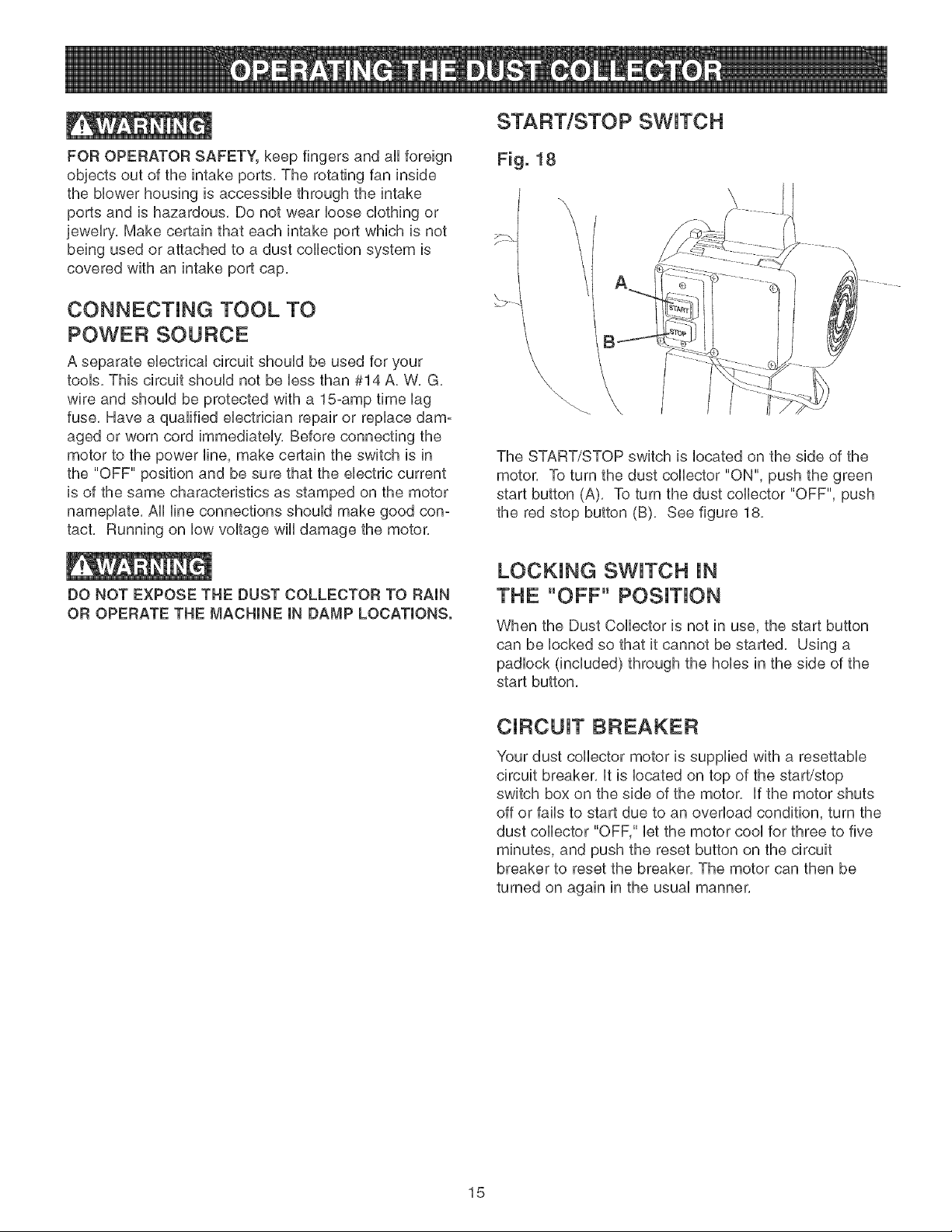
START/STOP SWITCH
Fig. 18
\
The START/STOP switch is Hocated on the side of the
motor. To turn the dust coHHector"ON", push the green
start button (A). To turn the dust coHHector"OFF", push
the red stop button (B). See figure 18.
LOCKING SWITCH JN
THE "OFF" POSiTiON
When the Dust CoHHectoris not in use, the start button
can be Hocked so that it cannot be started. Using a
padHock (incHuded) through the holies in the side of the
start button.
CiRCUiT BREAKER
Your dust coHHectormotor is suppHied with a resettabHe
circuit breaker. Htis Hocated on top of the start/stop
switch box on the side of the motor. Hfthe motor shuts
off or faiHsto start due to an overHoad condition, turn the
dust coHHector"OFF," Hetthe motor cooHfor three to five
minutes, and push the reset button on the circuit
breaker to reset the breaker. The motor can then be
turned on again in the usuaHmanner.
15
CHANGING MOTOR VOLTAGE 1, DBCONNECT THE DUST COLLECTOR FROM
THE POWER SOURCE.
MAKE CERTAIN THE DUST COLLECTOR mS
DBCONNECTED FROM THE POWER SOURCE.
The motor supplied with your Dust Collector is a duaU
voUtage 120/240-voUt, singb-phase motor, it is shipped
wired for 120-voUt application, if you choose 240-voUt to
operate your machine, the following instructions must
be followed,
2,
3,
4,
Remove the switch box cover,
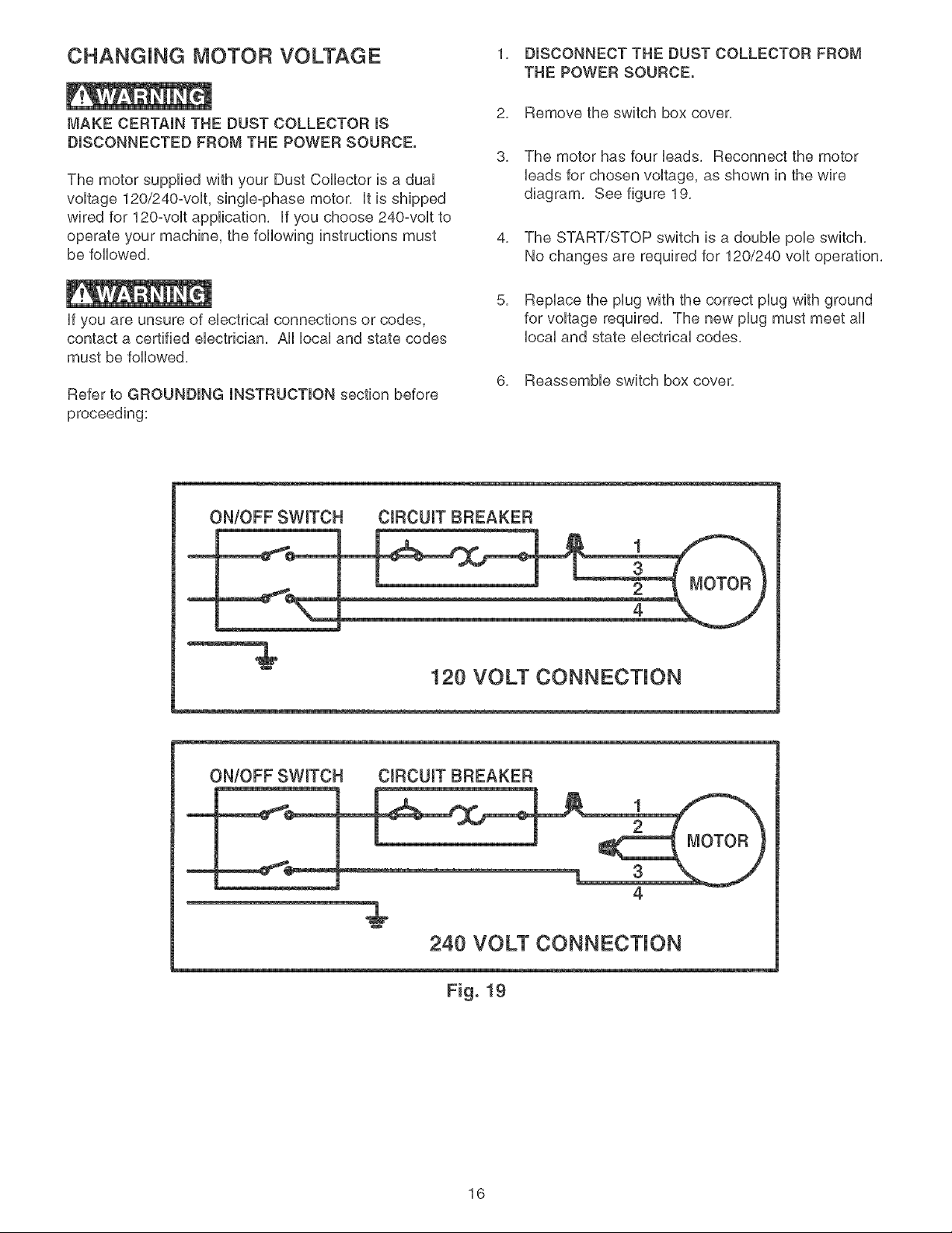
The motor has four leads, Reconnect the motor
leads for chosen voltage, as shown in the wire
diagram, See figure 19,
The START/STOP switch is a double pole switch,
No changes are required for 120/240 volt operation,
if you are unsure of electrical connections or codes,
contact a certified electrician, All local and state codes
must be followed,
Refer to GROUNDING INSTRUCTION section before
proceeding:
5, Replace the plug with the correct plug with ground
for voltage required, The new plug must meet all
local and state electrical codes,
6, Reassemble switch box cover,
ON/OFF SWITCH CmRCUmTBREAKER
1
4
120 VOLT CONNECTION
ON/OFF SWITCH CiRCUiT BREAKER
1
3
4
240 VOLT CONNECTION
EEiE i
Fig. 19
16
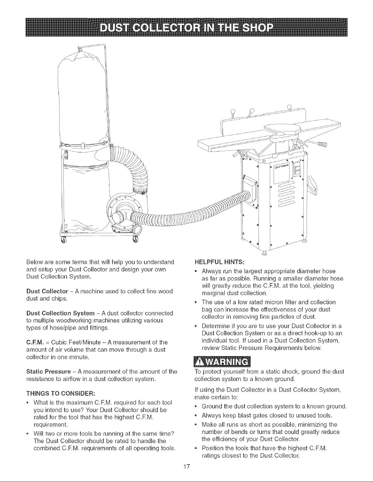
Belowaresometermsthatwiiihelpyouto understand
andsetupyourDustCollectoranddesignyourown
DustCollectionSystem,
DustCollector- A machineusedto collectfinewood
dustandchips,
DustCollectionSystem- Adustcollectorconnected
to multiplewoodworkingmachinesutilizingvarious
typesof hose/pipeandfittings,
C.F.M.= CubicFeet/Minute- A measurementof the
amountof airvolumethatcanmovethrougha dust
collectorin oneminute,
StaticPressure- A measurementof theamountof the
resistanceto airflowin a dustcollectionsystem,
THINGSTOCONSIDER:
WhatisthemaximumC,RM,requiredforeachtool
youintendto use?YourDustCollectorshouldbe
ratedforthetoolthathasthehighestC,RM,
•Wiii twoormoretoolsberunningat thesametime?
TheDustCollectorshouldberatedto handlethe
combinedC,RM,requirementsof alloperatingtools,
17
HELPFULHINTS:
, Alwaysrunthelargestappropriatediameterhose
asfaraspossible,Runningasmallerdiameterhose
wiiigreatlyreducetheC,F,M,at thetool,yielding
marginaldustcollection,
Theuseof a lowratedmicronfilterandcollection
bagcanincreasetheeffectivenessofyourdust
collectorin removingfineparticlesofdust,
Determineif youaretouseyourDustCollectorin a
DustCollectionSystemorasa directhook-uptoan
individualtookif usedin a DustCollectionSystem,
reviewStaticPressureRequirementsbelow,
Toprotectyourselffroma staticshock,groundthedust
collectionsystemto a knownground,
if usingthe DustCollectorina DustCollectorSystem,
makecertainto:
Groundthedustcollectionsystemtoaknownground,
Alwayskeepblastgatesclosedto unusedtools,
Makeall runsasshortas possible,minimizingthe
numberofbendsorturnsthatcouldgreatlyreduce
theefficiencyof yourDustCollector,
PositionthetoolsthathavethehighestC,RM,
ratingsclosesttotheDustCollector,

C.F.M.REQUIREMENTSFORTOOLS
Machine Minimum C.F._,_.Required Minimum Duct Diameter
Band Saw (12 to 16qnch) 350 C,F,M, 4qnch
BeWDbc Sander 450 C,F,M, 5qnch
DrHUPress 350 - 400 C,RM, 4qnch
Drum Sander (12 to 24qnch) 550 - 700 C,RM, 5qnch
Fbor Sweep 350 - 400 C,RM, 4 to 5qnch
Jointer (up to 8qnch) 350 - 400 C,RM, 4 to 5qnch
Jointer (over 8qnch) 450 - 550 C,RM, 5qnch
RadiaUArm Saw 450 - 600 C,RM, 5qnch
Miter Saw 450 - 600 C,RM, 5qnch
Router TaMe 200 C,F,M, 3qnch
Scroll Saw 200 C,F,M, 3qnch
Spindb Sander 400 C,F,M, 4qnch
TaMe Saw (lOqnch) 350 C,F,M, 4qnch
Thickness Haner (10 to 15qnch) 400 C,F,M, 4qnch
Thickness Planer (16 to 20qnch) 600 - 800 C,RM, 5 to 6qnch
STATIC PRESSURE FIEQUJF{EMENTS FOR A DUST COLLECTION SYSTEM
Using STEPS 1 thru 4 and the "Static Pressure Requirement Chart" you can determine the static pressure required
for your Dust Collector,
Step #1: Multiply the number of feet of Hose/Pipe times the appropriate inches rating,
Exampie; 40 feet of 4-inch diameter ribbed tubing x ,11 = 4.4 Total
Step #2: Multiply the fittings times the ratings and add them together,
Examp/e:Tw, o 90-degree Elbows (using 4qnch diameter Hose) = ,84 PLUS two 90-degree T-fittings = ,98
TotaJ = 1.82
Step #3:
Step #4:
Add 2.5 for the Machine Hook-up and "Dirty Bag" factors (1,5 for Hook-ups + 1,0 for Dirty Bag),
Total the above three calculations, This total should not exceed the maximum static
pressure for your Dust Collector,
Exaf_pie/4,4 (Total Step #1) x 1,82 (Total Step #2) + 2,5 (Total Step #3) = 8.72
For this example a Dust Collector with a Static Pressure rating of over 8.72 or higher is required.
See Product Specifications on page 2 for your dust collector maximum static pressure.
NOTE: To determine if you have met the Static Pressure Requirement when using a Dust Collection System, identify
the branch of the system with the highest static pressure requirement first, If you run your Dust Collection System with
more than one blast gate open, add the static pressure from all branches that are open to determine the total static
pressure requirements,
Static Pressure Requirement Chart
Size of Hose Hose/Pipe Ribbed Tubing 90-degree 90-degree 45-degree Machine "Dirty Bag"
Rigid Pipe (per foot) Elbow Elbow Tofitting Hook-Up Adjustment
(per foot}
3 .10 .15 .50 .60 .25 1.50 1.0
4 .07 .11 .42 .49 .21 1.50 1.0
5 .055 .08 .49 .55 .25 1.50 1.0
18
TopurchaseanyoftheDustCollectionAccessorieslistedbelow,visityournearestSearsStore,
VariousFittings:
21340 3=inchHoseCoupling 21341
21363 3=inch90=degreeElbow 21364
21365 3=inchY=Fitting 21366
21367 3=inchT=Fitting 21368
4-inchHoseCoupling
4-inch90-degreeElbow
4-inchYoFitting
4-inchToFitting
HOSe:
21370
21371
21372
21373
3-inch x lO-foot Flexible Hose
3-inch x 25-foot Flexible Hose
4-inch x lO-foot Flexible Hose
4-inch x 25-foot Flexible Hose
Blast Gates
21359 3-inch Blast Gate - Plastic
21361 3-inch Blast Gate - Aluminum
21360 4-inch Blast Gate - Plastic
21362 4-inch Blast Gate - Aluminum
Reducers:
21347 5 to 4-inch Reducer
21349 4 to 2-1/2-inch Reducer
21352 3 to 2-inch Reducer
21348
21351
21353
4 to 3-inch Reducer
3 to 2-1/2-inch Reducer
2-1/2 to lq/2-inch Reducer
Hose Clamps (Qty 2 per Pack)
21354 2-inch Hose Clamp
21356 3-inch Hose Clamp
21358 5-inch Hose Clamp
21355
21357
2-112-inch Hose Clamp
4-inch Hose Clamp
Dust Hoods:
21342
21343
21344
21345
21346
Jointer Dust Hood, 8-1/4" x 8-1/4" x 4" Diameter
Jointer Dust Hood, 10-1/4" x 8-1/2" x 4" Diameter
Table Saw Dust Hood, 12-1/4" x 12-1/4" x 4" Diameter
Table Saw Dust Hood, 14" x 14" x 4" Diameter
Universal Dust Hood, 6-1/4" x 6-1/4" x 4" Diameter
Floor Sweep:
21369 Floor Sweep
Kits:
21350
21375
Wall Mounting Kit
Dust Collector Accessory Kit
(contains: 6 - wall clamps, 12-screws & 12-anchors)
(contains: 2°#21372, 1°#21344, 1°#21342, 1°#21346, 4-#21360, 1 °#21369,
1°#21366, 1°#21350 & 5-#21357)
19
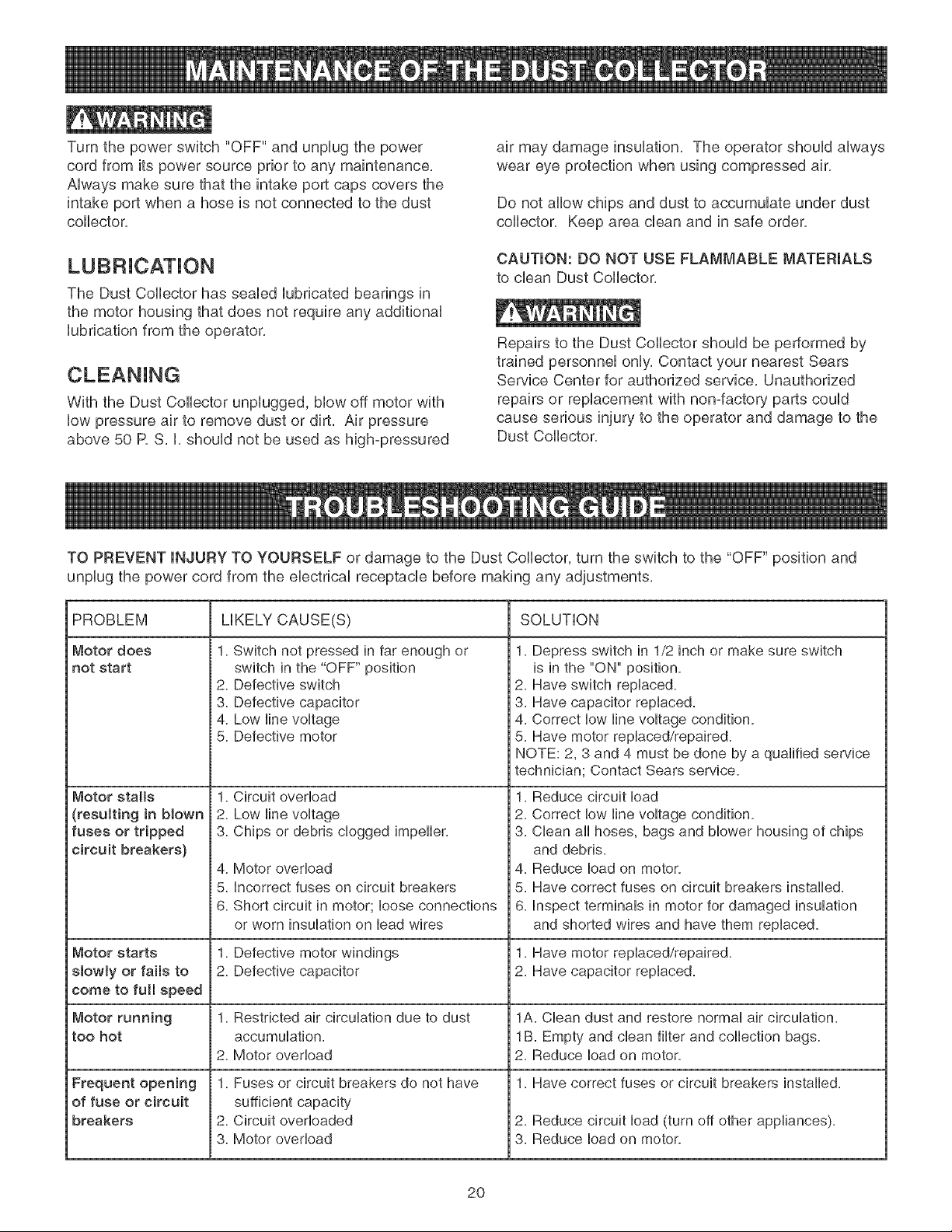
Turnthepowerswitch"OFF"andunplugthepower
cordfromitspowersourcepriortoanymaintenance,
Alwaysmakesurethattheintakeportcapscoversthe
intakeportwhena hoseis notconnectedtothedust
collector.
TheDustCollectorhassealedlubricatedbearingsin
themotorhousingthatdoesnotrequireanyadditional
lubricationfromtheoperator,
WiththeDustCollectorunplugged,blowoffmotorwith
lowpressureairto removedustordirt, Air pressure
above50 R S. I. shouldnotbe usedas high-pressured
airmaydamageinsulation.Theoperatorshouldalways
weareyeprotectionwhenusingcompressedair.
Donotallowchipsanddusttoaccumulateunderdust
collector.Keepareacleanandin safeorder.
CAUTION:DONOTUSEFLAMMABLEMATERIALS
tocleanDustCollector.
Repairsto theDustCollectorshouldbeperformedby
trainedpersonnelonly.ContactyournearestSears
ServiceCenterforauthorizedservice.Unauthorized
repairsor replacementwithnon-factorypartscould
causeseriousinjurytotheoperatoranddamageto the
DustCollector.
TOPREVENTINJURYTOYOURSELFor damageto theDustCollector,turntheswitchto the"OFF"positionand
unplugthepowercordfromtheelectricalreceptaclebeforemakinganyadjustments,
PROBLEM
Motor does
not start
Motor stalls
(resulting in blown
fuses or tripped
circuit breakers)
Motor starts
slowly or falls to
come to full speed
Motor running
too hot
Frequent opening
of fuse or circuit
breakers
LIKELY CAUSE(S) SOLUTION
1. Switch not pressed in tar enough or
switch in the "OFF" position
2. Detective switch
3. Detective capacitor
4. Low line voltage
5. Detective motor
1.
2.
3.
4.
5.
6.
1.
2.
1. Depress switch in 1/2 inch or make sure switch
is in the "ON" position.
2. Have switch replaced.
3. Have capacitor replaced.
4. Correct low line voltage condition.
5. Have motor replaced/repaired.
NOTE: 2, 3 and 4 must be done by a qualitied service
technician; Contact Sears service.
Circuit overload 1.
Low line voltage 2.
Chips or debris clogged impeller. 3.
Motor ovedoad 4.
incorrect tuses on circuit breakers 5.
Short circuit in motor; loose connections 6.
or worn insulation on lead wires
Detective motor windings 1.
Detective capacitor
1. Restricted air circulation due to dust
accumulation.
2. Motor overload
1. Fuses or circuit breakers do not have
sufficient capacity
2. Circuit overloaded
3. Motor overload
Reduce circuit load
Correct low line voltage condition.
Clean all hoses, bags and blower housing of chips
and debris.
Reduce load on motor.
Have correct tuses on circuit breakers installed.
inspect terminals in motor for damaged insulation
and shorted wires and have them replaced.
Have motor replaced/repaired.
2. Have capacitor replaced.
1A, Clean dust and restore normal air circulation.
1B. Empty and clean tilter and collection bags.
2. Reduce load on motor.
1. Have correct tuses or circuit breakers installed.
2. Reduce circuit load (turn off other appliances).
3. Reduce load on motor.
2O
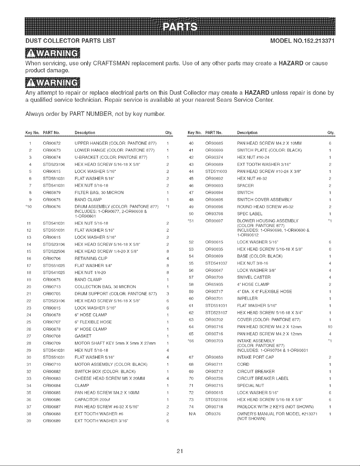
DUSTCOLLECTORPARTSUST MODELNO.152.213371
Whenservicing,useonlyCRAFTSMANreplacementparts,Useof anyotherpartsmaycreatea HAZARDor cause
productdamage,
Anyattemptto repairor replaceelectricalpartsonthisDustCollectormaycreatea HAZARDunlessrepairisdoneby
aqualifiedservicetechnician,Repairserviceisavailableat yournearestSearsServiceCenter,
Alwaysorderby PARTNUMBER,notbykeynumber,
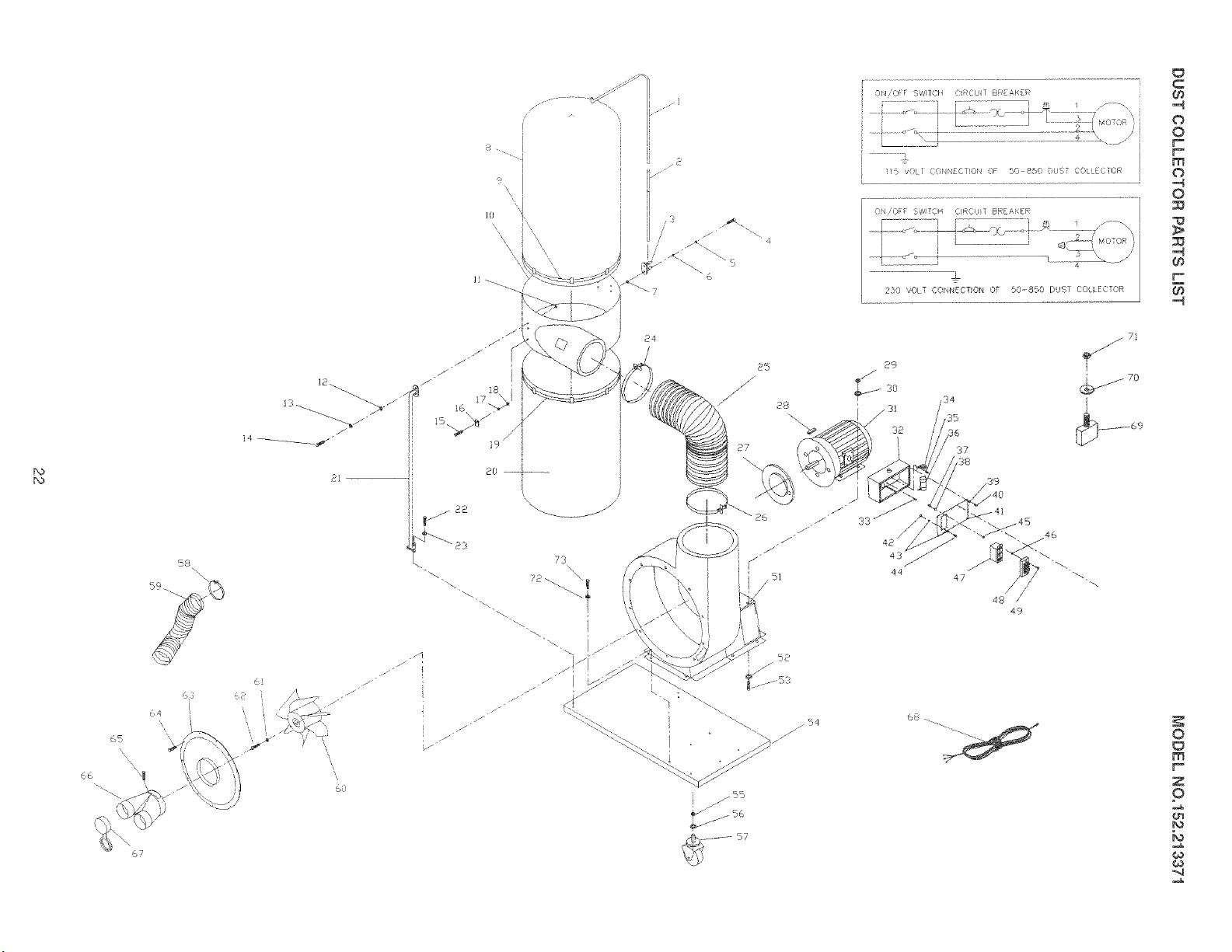
Key No. PART No.
1 OR90672
2 OR90673
3 OR90674
4 STD523106
5 OR90615
6 STD551031
7 STD541031
8 OR65979
9 OR90675
"10 OR90676
11 STD541031
12 STD551031
13 OR90615
14 STD523106
15 STD522506
16 OR90706
17 STD551025
18 STD541025
19 OR90675
20 OR90713
21 OR90705
22 STD523106
23 OR90615
24 OR90678
25 OR90707
26 OR90678
27 OR90708
28 OR90709
29 STD541031
30 STD551031
31 OR90710
32 OR90682
33 OR90683
34 OR90684
35 OR90685
36 OR90686
37 OR90687
38 OR90688
39 OR90689
Description Qty. Key No. PARTNo.
UPPER HANGER (COLOR: PANTONE 877) 1 40 0R90685
LOWER HANGE (COLOR: PANTONE 877) 1 41 OR90690
U-BRACKET (COLOR: PANTONE 877) 1 42 OR90374
HEX HEAD SCREW 5/1(5-18 X 5/8" 2 43 OR90689
LOCK WASHER 5/16" 2 44 STD511003
FLAT WASHER 5/16" 2 45 OR90692
HEX NUT 5/16-18 2 46 OR90693
FILTER BAG, 30 MICRON 1 47 OR90694
BAND CLAMP 1 48 OR90695
DRUM ASSEMBLY (COLOR: PANTONE 877) _1 49 OR90696
INCLUDES: 1-OR90677, 2-OR90608 & 50 OR93766
1-OR90601
"51 OR90697
HEX NUT 5/16-18 2
FLAT WASHER 5/16" 2
LOCK WASHER 5/16" 2
52 OR90615
HEX HEAD SCREW 5/16-18 X 5/8" 2
53 OR90635
HEX HEAD SCREW 1/4-20 X 5/8" 8
54 OR90699
RETAINING CLIP 4
55 STD541037
FLAT WASHER 1/4" 8
56 OR90647
HEX NUT 1/4-20 8
57 OR90700
BAND CLAMP 1
58 OR65935
COLLECTION BAG 30 MICRON 1
59 OR90717
DRUM SUPPORT (COLOR: PANTONE 877) 3
60 OR90701
HEX HEAD SCREW 5/16-18 X 5/8" 6
61 STD551031
LOCK WASHER 5/16" 6
62 STD523107
8" HOSE CLAMP 1
83 OR90702
6" FLEXIBLE HOSE 1
84 OR90716
8" HOSE CLAMP 1
85 OR90716
GASKET 1
*66 OR90703
MOTOR SHAFT KEY 5ram X 5ram X 27rnm 1
HEX NUT 5/16-18 4
FLAT WASHER 5/16" 4 87 OR90650
MOTOR ASSEMBLY (COLOR: BLACK) 1 88 OR90711
SWITCH BOX (COLOR: BLACK) 1 89 OR90712
CHEESE HEAD SCREW M5 X 20MM 4 70 OR90728
CLAMP 1 71 OR90715
PAN HEAD SCREW M4,2 X 10MM 1 72 OR90615
CAPACITOR 200uf 1 73 STD523106
PAN HEAD SCREW #6-32 X 5/16" 2 74 OR90718
EXT TOOTH WASHER #6 2 N/A OR9376
EXT TOOTH WASHER {5/16" 6
Description Qty.
PAN HEAD SCREW M4.2 X 10MM 6
SWITCH PLATE (COLOR: BLACK) 1
HEX NUT #10-24 1
EXT TOOTH WASHER 3/16" 2
PAN HEAD SCREW #10-24 X 3/8" 1
HEX NUT #6-32 2
SPACER 2
SWITCH 1
SWITCH COVER ASSEMBLY 1
ROUND HEAD SCREW #6-32 2
SPEC LABEL 1
BLOWER HOUSING ASSEMBLY "1
(COLOR: PANTONE 877)
INCLUDES: 1-OR90698 1-OR90600 &
1-OR90812
LOCK WASHER 5/16" 6
HEX HEAD SCREW 5/18-18 X 5/8" 6
BASE (COLOR: BLACK) 1
HEX NUT 3/8-16 4
LOCK WASHER 3/8" 4
SWIVEL CASTER 4
4" HOSE CLAMP 2
4" DIA. X 6' FLEXIBLE HOSE 1
IMPELLER 1
FLAT WASHER 5/16" 1
HEX HEAD SCREW 5/16-18 X 3/4" 1
COVER (COLOR: PANTONE 877) 1
PAN HEAD SCREW M4.2 X 12mrn 10
PAN HEAD SCREW M4.2 X 12rnrn 4
INTAKE ASSEMBLY "1
(COLOR: PANTONE 877)
INCLUDES: 1-OR90704 & 1-OR90601
INTAKE PORT CAP 2
CORD 1
CIRCUIT BREAKER 1
CIRCUIT BREAKER LABEL 1
SPECIAL NUT 1
LOCK WASHER 5/16" 8
HEX HEAD SCREW 5/16-18 X 5/8" 8
PADLOCK WITH 2 KEYS (NOT SHOWN) 1
OWNER'S MANUAL FOR MODEL #213371 1
(NOT SHOWN)
21
i
9 "\\ !
ON/OFF S_,'[Sii _RCUN BR AKEB_
!l_i vOLT DONN£U1,Or4 OF 50 850 DUST CO ECTOR
2}0 VOLT CONI/EDTION OF 50-850 DUST COLLECTOR
C
60
,,H
o
O
r"-
F
m
o
,,d
O
,,d
0_
58
63
_4
65
"\\
67
85
_/ 28
27
f !!
29
_54
52
_$3
57
37
38
$9
47
4s/!
49
0
m
z
P
N

NOTES
23

NOTES
24

anuai Propietario
0
1-1/2 cabaHos de fuerza (servicio continuo)
2.1 cabaHos de fuerza (ma×imo desarroHado)
1200 C.F.M. (pies c_bicos pot minuto)
3450 R.PoM. (R.PoM. sin carga)
No. de Mode_o
152.213371
c uS
PARA SU SEGURIDAD PERSONAL:
Lea y obedezca todas Ras
tnstrucciones de Seguddad y
Funcionamiento antes de accionar
este CoUector de PoUvo.
Linea de Ayuda al Cliente
1-800-897-7709
Sirvase tenet listo su No. de
Modelo y No. de Serie
I
J
,I
li
I
Sears, Roebuck and Co., Hoffman Estates, JL 60179 U.S.A.
No. de Pieza OR93765
25
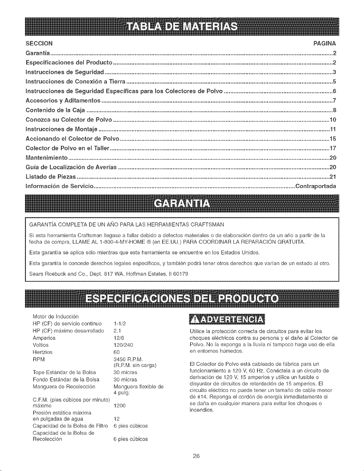
SECCION PAGINA
Garant_a...........................................................................................................................................................................2
Especificacionesde1Producto.....................................................................................................................................2
lnstrucciones de Seguddad .......................................................................................................................................... 3
lnstrucciones de Cone×i6n a Tierra ............................................................................................................................. 5
lnstrucciones de Seguddad Especfficas para Jos CoJectores de Potvo .................................................................. 6
Accesorios y Aditamentos ............................................................................................................................................ 7
Contenido de ta Caia ..................................................................................................................................................... 8
Conozca su CoJector de Potvo ................................................................................................................................... 10
lnstrucciones de Montaje ............................................................................................................................................ 11
Accionando eJ CoJector de Potvo ............................................................................................................................... 15
CoJector de PoJvo en el Taller ..................................................................................................................................... 17
Ma ntenimiento .............................................................................................................................................................. 20
Guia de LocaJizaci6n de Av÷das ................................................................................................................................ 20
Listado de Piezas ......................................................................................................................................................... 21
lnformaci6n de Servicio .......................................................................................................................... Contraportada
GARANTiA COMPLETA DE UN ANO PARA LAS HERRAMIENTAS CRAFTSMAN
Siesta herramienta Craftsman Ilegase a failar debido a defectos materiales o de elaboraci6n dentro de un a_o a partir de la
fecha de compra, LLAME AL 1-800-4-MY-HOME @ (en EE.UU.) PARA COORDINAR LA REPARACION GRATUITA.
Esta garantfa se aplica s61o mientras que esta herramienta se encuentre en Ios Estados Unidos.
Esta garanfia Je concede derechos legales especificos, y tambien podra tener otros derechos que var[an de un estado al otro.
Sears Roebuck and Co., Dept. 817 WA, Hoffman Estates, IJ60179
Motor de Inducci6n
HP (CF) de servicio continuo
HP (CF) m4,ximo desarroJlado
Amperios
Voltios
Hertzios
RPM
Tope Est#,ndar de la BoJsa
Fondo Estandar de la Bolsa
Manguera de Recolecci6n
C=RM= (pies c0bicos por minuto)
maximo
Presi6n estatica mgxima
en pulgadas de agua
Capacidad de la BoJsa de Filtro
Capacidad de la BoJsa de
Recolecci6n
1-1/2
2=1
12/6
120/240
60
3450 R=RM=
(R=RM= sin carga)
30 micras
30 micras
Manguera flexible de
4 pulg=
1200
12
6 pies cubicos
6 pies c0bicos
Utilice Ia protecci6n correcta de circuitos para evitar los
choques eIectricos contra su persona y el daf_o al Colector de
Polvo. No Ia exponga a la Iiuvia ni tampoco haga uso de ella
en entornos h0medos=
El Colector de PoJvo esta cableado de f9brica para un
funcionamiento a 120 V, 60 Hz= Con6ctela a un circuito de
derivaci6n de 120 V, 15 amperios y utiIice un fusible o
disyuntor de circuitos de retardaci6n de 15 amperios. El
circuito electrico no puede tener un tamaSo de cable menor
de #14= Reponga el cord6n de energia inmediatamente si
se da[ia en cualquier manera para evitar Jos choques o
incendios=
26
INSTRUCCIONES GENERALES DE
E! funcionamiento de un Colector de Polvo puede resultar
peligroso si se hace caso omiso de Ia seguridad y del sentido
com0n. El operario debe estar familiarizado con el fun-
cionamiento de Ia herramienta. Lea este manual para enten-
der su Colector de Polvo. NO OPERE este Colector de Polvo
si no entiende cabalmente Ias limitaciones de dicha her-
ramienta. NO reaIice modificaciones de cualquier tipo a este
Colector de Polvo. RECUERDE; Usted es responsable de su
propia seguridad.
ANTES DE UTILIZAR EL COLECTOR DE
POLVO
Para evitar las heridas graves y el dafio a la herramienta, lea
y obedezca todas Ias instrucciones de Seguridad y Operaci6n
antes de operar el Colector de Polvo.
1. LEA a consciencia el Manual del Propietario. APRENDA
c6mo hacer uso de esta herramienta para sus aplica-
ciones disehadas.
2. CONECTE TODAS LAS HERRAMIENTAS A TIERRA.
Si la herramienta se suministra con un enchufe de 3
machos, se le debe enchufar a un tomacorrientes que
disponga de 3 contactos electricos. El tercer macho se
utiliza para conectar Ia herramienta a tierra y ofrecer
protecci6n contra los choques etectricos accidentaIes.
NO quite el tercer macho. Vea las Instrucciones de
Conexi6n a Tierra.
3. EVITE UN ENTORNO LABORAL PELIGROSO. NO
utilice las herramientas electricas en un entorno h0medo,
ni tampoco las exponga a Iluvia.
4. NO utilice herramientas electricas si hay gases o liquidos
infiamables presentes.
5. MANTENGA SlEMPRE su zona de trabajo limpia, bien
alumbrada y organizada. NO TRABAJE en un entorno
con superficies de piso resbalosas a consecuencia de los
escombros, la grasa y Ia cera.
6. MANTENGA ALEJADOS A LOS NtNOS Y VlSlTANTES,
NO permita que haya personas en Ia zona inmediata de
trabaio, particuIarmente cuando Ia herramienta electrica
se encuentre en funcionamiento.
7.
8.
NO FUERCE LA HERRAMIENTA a realizar operaciones
para las cuales no fue disehada. Realizara una labor mas
segura y de mejor calidad si se Ie utiliza soIamente para
realizar operaciones para Ias cuales fue diseSada.
UTILIOE VESTIMENTA APROPIADA. NO vista ropa
holgada, guantes, corbatas ni art[culos de joyer[a. Estos
art[cu!os pueden quedar atrapados en la m&quina
durante Ias operaciones y tirar del operario, atrayendoIo
hacia las piezas en movimiento. El usuario debe Ilevar
una cubierta protectora sobre el cabello, si tiene
cabeIIera larga, para impedir el contacto con cualquier
pieza en movimiento.
g.
UTlUCE PROTECCION OCULAR SIEMPRE. Cualquier
herramienta mecb_nica puede expulsar escombros hacia
los oios durante las operaciones, causando daho ocular
grave y permanents. Los anteojos de uso cotidiano NO
son gafas de seguridad. Utilice gafas de seguridad
SlEMPRE (que cumplan con la normativa Z87.1 de ANSI)
cuando vaya a operar herramientas mec_.nicas. Las
gafas de seguridad estan disponibles en las tiendas de
Ventas ai Detal de Sears.
10.
11.
12.
13.
14.
15.
16.
17.
18.
19.
20.
UTILICE PROTECCION AUDITIVA SlEMPRE. El
algod6n por s[ solo no constituye un dispositivo de
protecci6n aceptable. El equipo auditivo debe cumplir
con las normativas $3.19 de ANSI.
SIEMPRE DESENCHUFE LA HERRAM_ENTA DEL
TOMACORRIENTES cuando vaya a realizar ajustes,
cambiar piezas o realizar cualquier class de
mantenimiento.
MANTENGA LOS ESCUDOS DE PROTECCION EN SU
SITIO Y EN BUEN ESTADO DE FUNCIONAMIENTO.
EVITE EL ARRANQUE ACCIDENTAL. Aseg0rese de
que el interruptor de potencia se encuentre en la posici6n
de "APAGADO" antes de enchufar el cord6n de potencia
en el tomacorrientes.
QUITE TODAS LAS HERRAMIENTAS DE MANTENI-
MIENTO de la zona inmediata antes de encender la
herramienta.
SOLO UTILICE ACCESOR!OS RECOMENDADOS. El
uso de accesorios incorrectos o poco apropiados puede
ocasionar heridas graves al operario y ocasionar daho a
la herramienta. Si tiene dudas, consults el manual de
instrucciones que se adiunta con el accesorio especifico.
JAMAS DEJE UNA HERRAMIENTA EN FUNCIONA-
MIENTO SIN ,&TENDER. Conmute el interruptor de
energ[a a Ia posici6n de apagado. NO abandons Ia
herra-mienta hasta que esta se haya detenido por com-
pleto.
NO SE PARE SOBRE LA HERRAMIENTA. Pueden pro-
ducirse heridas graves si la herramienta se vuelca o si
usted hace contacto con la herramienta accidentalmente.
NO ALMACENE nada por encima ni cerca de la m_quina
en donde alguien pueda intentar pararse en la herra-
mienta para alcanzarlo.
MANTENGA SU EQUILIBRJO, NO se extienda sobre la
herramienta. Haga uso de zapatos con suela de caucho
resistente ai aceite. Mantenga el piso libre de escombros,
grasa o cera.
MANTENGA SUS HERRAMIENTAS CUIDADOSAo
MENTE. Mantenga sus herramientas Iimpias yen buen
estado. Mantenga afiIadas todas las hoias y brocas.
27
21. REVISE SI HAY PIEZAS DANADAS ANTES DE CADA
USO DE LA HERRAMIENTA. Revise todos los protec-
tores cuidadosamente para comprobar que funcionan
correctamente y que no estan daffados, y que realizan
sus funciones diseffadas correctamente. Revise el
alineamiento, la fijaci6n o la ruptura de Ias piezas en
movimiento. Cualquier protector u otra pieza que se
encuentre daffada debe repararse o reemplazarse
[nmediatamente.
22. HAGA SU TALLER A PRUEBA DE NtNOS quitando las
Ilaves del interruptor, desenchufando Ias herramientas de
los tomacornentes, y mediante el uso de candados.
23. NO OPERE LA HERRAMIENTA BAJO LA tNFLUENCIA
DE LAS DROGAS O DEL ALCOHOL.
24. AFIANCE TODO EL MATERIAL. Siempre que resulte
posible, utilice abrazaderas o plantilias para asegurar el
material. Esto ofrece mayor seguridad que intentar
sujetar el material con sus propias manos.
25. MANTENGASE ALERTA, ESTE CONSCIENTE DE LO
QUE HACE, Y UTILICE SENTIDO COMUN CUANDO
VAYA A OPERAR UNA HERRAMIENTA ELECTRICA,
NO UTILICE LA HERRAMIENTA Sl ESTA CANSADO O
BAJO LA INFLUENCIA DE DROGAS, ALCOHOL O
MEDICAMENTOS. Un momento de descuido durante el
uso de herramientas electricas puede resuttar en
lesiones personales graves.
26. UTILICE SIEMPRE UNA CARETA CONTRA EL POLVO
PARA EVtTAR ASPIRAR POLVOS PELIGROSOS O
PART[CULAS EN EL AIRE, [ncluyendo polvo e madera,
polvo de siJice cristalino y polvo de asbesto. Diriia las
part[culas en direcci6n opuesta a! rostro y el cuerpo.
Opere la herramienta siempre en una zona bien ventilada
y proporcione Ia remoci6n apropiada de! polvo. Utilice un
sistema de recolecci6n de polvo siempre que sea posF
ble. La exposici6n al polvo puede ocasionar daBos respP
ratorios graves y permanentes u otras heridas, incluyem
do silicosis (una enfermedad pulmonar grave), cancer y
la muerte. Evite aspirar el polvo y evite el contacto pro-
Iongado con el polvo. El permitir Ia entrada deI polvo en
su boca u o]os, o deiar que permanezca sobre su pieI,
puede promover a! absorci6n de material dafiino. Utilice
protecci6n respiratoria de ajuste correcto, aprobada per
NIOSH/OSHA y apropiada para Ia exposici6n al polvo, y
lave las zonas expuestas con jab6n y agua.
27. UTILICE UNA EXTENSION ELECTRICA CORRECTA Y
EN BUEN ESTADO. Cuando vaya a hacer use de una
extensJ6n electrica, aseg0rese de utilizar una que sea Jo
suficbntemente fuerte come para transportar Ia cornente
a ser utiJizada por su herramienta. Tenga Ia bondad de
referirse al cuadro de calibres recomendados (AWG)
para las extensiones electricas para el dimensionamiento
correcto de la extensi6n electrica. S[ tiene dudas, utiJice
la siguiente extensi6n de mayor caJibre.
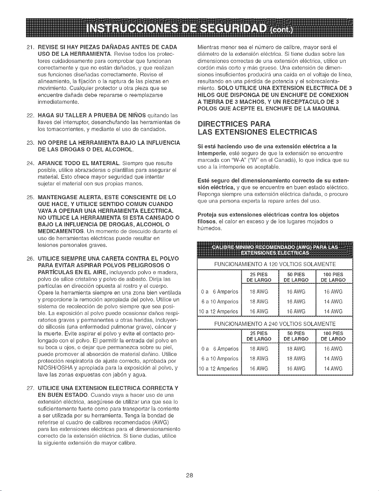
Mientras menor sea eI n0mero de calibre, mayor sera el
diAmetro de la extensi6n electrica. Si tiene dudas sobre las
dimensiones correctas de una extensi6n eIectrica, utiIice un
cord6n mas corto y mas grueso. Una extensi6n de dimen-
siones insuficientes producira una ca[da en el voJtaje de ffnea,
resuItando en una perdida de potencia y el sobrecalenta-
miento. SOLO UTIL[CE UNA EXTENSION ELECTR[OA DE 3
HILOS QUE D[SPONGA DE UN ENCHUFE DE CONEXION
A TJERRA DE 3 MACHOS, Y UN RECEPTACULO DE 3
POLOS QUE ACEPTE EL ENCHUFE DE LA MAQUINA.
D[RECTRICES PARA
LAS EXTENSIONES ELECTRICAS
Si estA haciendo uso de una extensi6n el_ctrlca a [a
intemperle, est6, seguro de que [a extensi6n se encuentre
marcada con "W-A" ("W" en el CanadA), Io que indica que su
use a la intemperie es aceptable.
Est6 seguro de[ dimensionamiento correcto de su exten-
si6n el_ctrica, y que se encuentre en buen estado eiectrico.
Reponga siempre una extensi6n electrica daffada, o procure
que una persona experta Ia repare antes del use.
Proteja sus extensiones electricas contra los objetos
filosos, el cater en exceso y de los lugares mojados o
humedos.
FUNCIONAMIENTO A 120 VOLTIOS SOLAMENTE
0 a 6Amperios
6 a 10 Amperios
10 a 12 Amperios
25 P(ES
DE LARGO
18 AWG
18 AWG
16 AWG
50 P(ES 100 P(ES
DE LARGO DE LARGO
16 AWG 16 AWG
16 AWG 14 AWG
16 AWG 14 AWG
FUNCIONAMIENTO A 240 VOLTIOS SOLAMENTE
0 a 6Amperios
6 a 10 Amperios
10 a 12 Amperios
25 P(ES
DE LARGO
18 AWG
18 AWG
16 AWG
50 P(ES
DE LARGO
18 AWG
18 AWG
16 AWG
100 PIES
DE LARGO
16 AWG
14 AWG
14 AWG
28
ESTA HERRAMIENTA DEBE ESTAR CONECTADA A
TIERRA DURANTE EL USO PARA PROTEGER AL
OPERAR_O DE LOS CHOQUES ELECTR_COS.
EN EL CASO DE UN MALFUNCIONAMJENTO O AVERIA, la
conexi6n a tierra ofrece el trecho de menor resistencia para Ia
corriente el6ctrica y reduce el riesgo de los choques el6ctri-
cos= Esta herramienta viene equipada con un cord6n eIectrico
que dispone de un conductor de conexi6n a tierra para el
equipo asf como un enchufe de conexi6n a tierra= El enchufe
DEBE estar enchufado a un tomacorrientes adaptado que
haya sido correctamente instalado y conectado a tierra de
acuerdo con TODOS los c6digos y ordenanzas municipaJes=
TOMACORRBENTES
CONECTADO A TmERRA--
OREJETA DE
ADAPTADOR
AGUJEROS
NO MODIFJQUE EL ENCHUFE SUMINISTRADO. Haga que
un electricista calificado instaJe el tomacordentes apropiado si
el enchufe no cabe en el tomacorrientes.
LA CONEXJON ELECTRICA INCORRECTA del conductor de
conexi6n a tierra para el equipo puede resultar en el riesgo
de choques electricos= El conductor con el aislamiento verde
(con o sin rayas amarillas) es el conductor de conexi6n a
tierra para el equipo. NO conecte el conductor de conexi6n a
tierra para eJ equipo a una terminaci6n viva si resulta nece-
sario reparar o reemplazar el cord6n el6ctrico o el enchufe.
CONSULTE con un electricista calificado o personal de
servicio si no entiende Jas instrucciones de conexi6n a tierra
compJetamente, o si no esta seguro que la herramienta esta
debidamente conectada a tierra.
El motor suministrado con su Colector de PoIvo es un motor
de voJtaje doble 120/240 monofasico. Se envia cableada para
el funcionamiento a 120 voJtios. JamAs conecte el alambre
verde a un terminal vivo. Revise OPERAOJON DEL COLEC-
TOR DE POLVO para las direcciones sobre el cambio de
voitaje del motor.
SOLO UT_LICE UNA EXTENSION ELECTRJCA DE 3 HJLOS
QUE DJSPONGA DE UN ENCHUFE DE CONEXION A
TIERRA DE 3 MACHOS, Y UN RECEPTACULO DE 3
POLOS QUE ACEPTE EL ENCNUFE DE LA MAQUJNA.
REPONGA CUALQUJER CORDON DANADO O GASTADO
tNI_,IED_ATAMENTE=
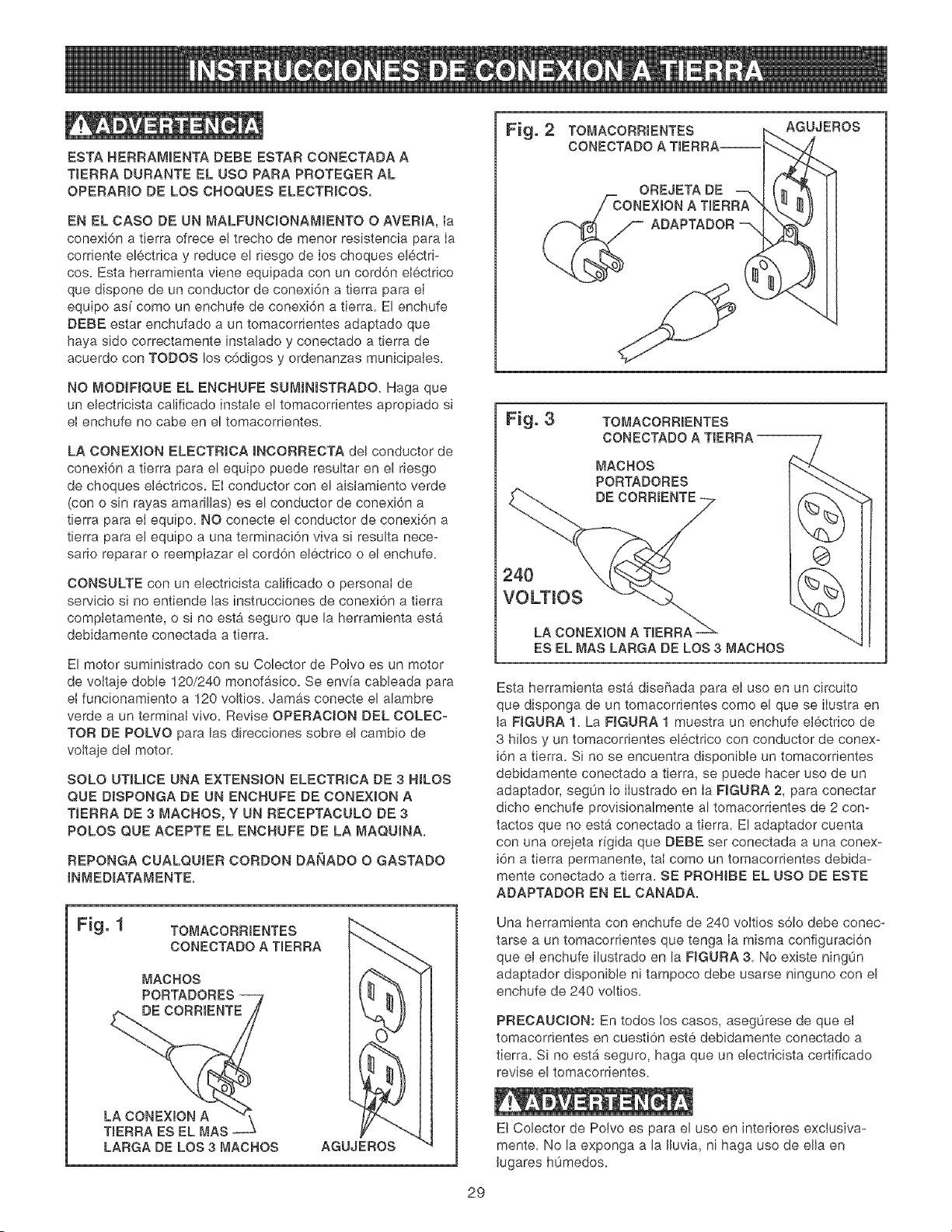
Fig. 3 TOMACORRmENTES
CONECTADO A TIERRA
MACHOS
PORTADORES
DE CORRmENTE
240
VOLTIOS
LA CONEXION A TBERRA
ES EL MAS LARGA DE LOS 3 MACHOS
Esta herramienta estb_disehada para el uso en un circuito
que disponga de un tomacorrientes como el que se ilustra en
Ja FJGURA 1. La FJGURA 1 muestra un enchufe electrico de
3 hilos y un tomacorrientes electrico con conductor de conex-
i6n a tierra. Si no se encuentra disponible un tomacorrientes
debidamente conectado a tierra, se puede hacer uso de un
adaptador, seg0n Io ilustrado en Ia FJGURA 2, para conectar
dicho enchufe provisionalmente al tomacorrientes de 2 con-
tactos que no est#, conectado a tierra. El adaptador cuenta
con una orejeta rigida que DEBE ser conectada a una conex-
i6n a tierra permanente, taI como un tomacorrientes debida-
mente conectado a tierra. SE PROHJBE EL USO DE ESTE
ADAPTADOR EN EL CANADA.
Fig. 1 TOMACORRmENTES _._
co°,c,,oo,,,,oo,
MACHOS I ('_'_ J l
PORTADORES .....} I l, _ Ht_\ I I
Una herramienta con enchufe de 240 voItios s6to debe conec-
tarse a un tomacorrientes que tenga Ia misma configuraci6n
que el enchufe ilustrado en la FJGURA 3= No existe ningun
adaptador disponible ni tampoco debe usarse ninguno con el
enchufe de 240 voJtios.
PRECAUOION: En todos los casos, aseg0rese de que ei
tomacorrientes en cuesti6n este debidamente conectado a
tierra. Si no esta seguro, haga que un electricista certificado
revise el tomacorrientes.
Ei Colector de Poivo es para el uso en Jnteriores exciusiva-
mente= No la exponga a Ja JJuvia, ni haga uso de ella en
Jugares hOmedos=
29
JNSTRUCCJONES DE SEGURJDAD
ESPECJNCAS PARA LOS
COLECTORES DE POLVO
El funcionamiento de cualquier colector de polvo puede tener
come consecuencia la expulsi6n de escombros hacia sus
ojos, Io que puede resuitar en heridas oculares graves.
UTILiOE SlEMPRE Gafas de Protecci6n (que cumplan con Ia
normativa Z87.1 de ANSi) cuando vaya a hacer use del
colector de polvo. Las Gafas de Seguridad est_in disponibles
en las tiendas Sears de ventas al detaL Mantenga los puF
gares y los dedos alejados de los puertos de admisi6n.
Las precauciones basicas deben acatarse en todo momento
cuando se utiliza un colector de polvo. Cumpla con las
instrucciones indicadas a continuaci6n para reducir el riesgo
de lesiones, cheques electricos o incendios:
1. LEA y entienda el manual de instrucciones antes de
poner el colector de polvo en funcionamiento.
2. NO OPERE ESTA MAQUiNA hasta que se encuentre
ensamblada e instaIada conforme a las instrucciones.
3. ASESORESE CON SU SUPERVISOR, instructor u otra
persona experta si no esta familiarizado con el uso de
esta mb,quina.
12. UTlUCELO s61o como se describe en este manual
SOLO utilice los accesofios recomendados per Sears.
13.
NO tire de[ colector de polvo mediante el cord6n de
energia. JAMAS permita que el cord6n de potencia entre
en contacto con bordes filosos, superficies calientes,
aceite o grasa.
14. NO desenchufe el colector de poIvo tirando del cord6n de
energia. SlEMPRE agarre el enchufe en vez deI cord6n.
15. REPONGA un cord6n daF_ado inmediatamente. NO utiF
ice un cord6n o enchufe que est6n daffados. Si el colec-
tor de polvo no funciona debidamente, o si ha sido daffa-
do, dejado a Ia intemperie o si ha entrado en contacto
con el agua, devu61valo a un Centre de Servicio Sears
para recibir servicio.
16. NO utiIice ei colector de polvo como juguete. NO LO
UTILJCE si hay niffos presentes.
17.
NO inserte los dedos o cuerpos extraffos dentro del
puerto de entrada de polvo. Debe alejar el cabello, Ia
ropa holgada, Ios dedos y demAs extremidades de las
aberturas y piezas en movimiento del colector de poIvo.
18. NO utiIice el colector de polvo sin que Ia bolsa guarda-
polvo se encuentre en su sitio y debidamente asegurada.
4.
NO PERMITA el colector de polvo permanezca enchufa-
do al tomacorrientes. El colector de polvo debe desen-
chufarse del tomacorrientes cuando no se encuentre en
use y antes de rendir servicio, cambiar bolsas, destupir y
Hmpiar,
5. COLOQUE SIEMPRE el interruptor de energia en
"APAGADO" antes de desenchufar el colector de polvo.
6. PARA REDUCIR EL RiESGO DE CHOQUES ELECTRI-
COS, no utilice [a maquina a [a intemperie. No la expon-
ga a la Iluvia. Aimac6neia baio techo. Utiffcela para
recoger materiaI seco soJamente.
7.
OBEDEZCA todos los c6digos el6ctricos y de seguridad,
incluyendo e! C6digo EI6ctrico Nacional (NEC) y las
Normas de Satud y Seguridad en el Trabajo (OSHA).
Todas Ias conexiones y cableado el6ctrico deben ser
realizados s61o per personal competente.
8. NO maneje et enchufe ni el colector de polvo con las
manes mojadas.
9.
NO UTILICE el colector de polvo para recoger ffquldos
infiamables o combustibles, tales como Ia gasolina.
JAMAS utilice et colector de polvo cerca de cualquier
ffquido inflamable o combustible.
10. UTILICE el colector de polvo para recoger materlales de
madera sotamente. NO LO UTILICE para recoger viru-
tas, poivo nl piezas de metal.
19.
UTIUOE SIEMPRE compuertas de seguridad para cubrir
los puertos de poIvo cuando el colector de polvo no se
encuentre en use o cuando se esta montado sobre una
superficie de apoyo para el almacenamiento.
20.
La bolsa guardapolvo debe ser JNSPECCIONADA PERIO-
DJOAMENTE per si exlste cualquier cortadura, desgarre
o rompedura. JAMAS opere el colector de potvo con una
bolsa o manguera de vac[o que este daFiada.
21. El colector de potvo SOLO esta diseF_ado para el use
domestico o el uso industrial ligero.
22. CONECTE el colector de polvo a un tomacorrientes
debidamente conectado a tierra. Vea las instrucciones de
conexi6n a tierra.
23. INFORMACION ADICIONAL sobre el funcionamiento
seguro y correcto de este producto esta disponible de
parte del National Safety Council, 1121 Spring Lake
Drive, Itasca, IL 60143-3201 en el Manual de Prevenci6n
de Accidentes para Operaclones Industriales as[ come en
las Hojas de Datos de Seguridad suministradas per et
NSC. Tenga Ia bondad de referlrse tambien aI ANSI 01.1,
RequisJtos de Seguridad para la Maquinaria de
Ebanister[a de la American National Standards Institute, y
el Reglamento 1910.213 OSHA del U.S. Department of
Labor.
24. GUARDE ESTAS JNSTRUCCIONES. Refi6rase a elias
con frecuencia y utilicelas para instruir a otros usuarios_
11. JAMAS utilice el colector de pelves para disipar emana-
clones o humo. JAMAS recoja cualquier cosa que este
ardiendo o emitiendo humo, as[ como cigarrillos, f6sforos
o cenizas calientes.
3O

ACCESOFHOS DJSPONJBLES
Visite su Departamento de Ferreteffa de Sears o consulte el
Catalogo de Herramientas EI6ctricas y de Mane de Sears
para los siguientes accesorios:
ARTiCULO
Boisa de fiRro de 30 mieras
(superior)
Bolsa de fiRro de 5 micras
(superior)
Bolsa de recobcci6n de plb,stico
(fond@
Manguera flexible 4 pulg.
dibmetro x 10 pies
Manguera flexible 4 pulg.
dib,metro x 25 pies
Conectores de accesorJos varies
NUMERO DE EX_STENCJA
21379
21380
21381
21372
21373
ConsuRar el catAIogo
o la tienda
Sears podra recomendar otros accesorios no listados en este
manual.
CensuRe su Departamento de Ferreterfa de Sears mas
cercano o el Catalogo de Herramientas Ebetricas y de Mano
de Sears para otros accesorios.
No utilice ningOn accesorio a menos que haya Ie[do cabal-
mente el Manual deJ Propietario para dicho accesorio.
S61o utilice accesorios recomendados para este Cobctor de
Polvo. El use de otros accesorios puede ocasionar bsiones
graves y producir daBo al Colector de Polvo.
31
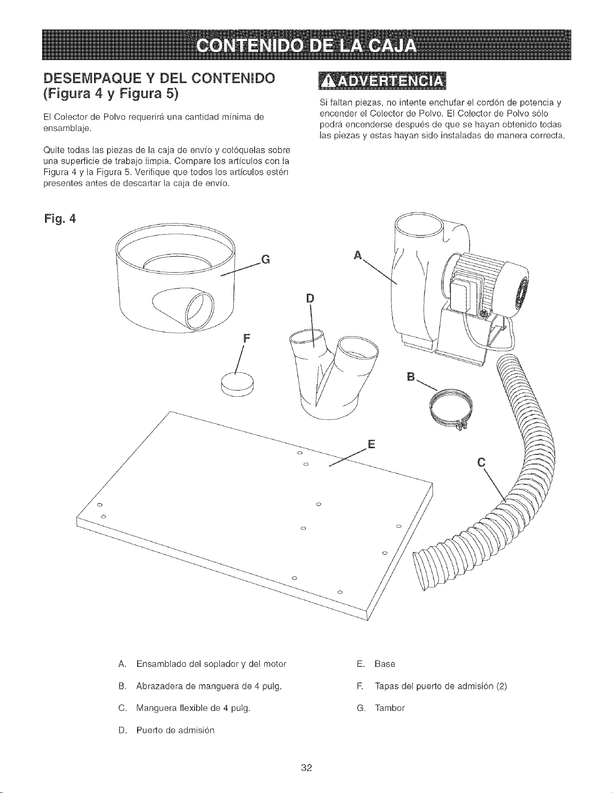
DESEMPAQUE Y DEL CONTENJDO
(Figura 4 y Figura 5)
El Colector de Polvo requerira una cantidad mfnima de
ensamblaje.
Quite todas Ias piezas de la caja de env[o y coI6quelas sobre
una superficie de trabaio Iimpia. Compare Ios art[culos con Ia
Figura 4 y Ia Figura 5. Verifique que todos los art[cu!os esten
presentes antes de descartar la caja de env[o.
Si faltan piezas, no intente enchufar el cord6n de potencia y
encender e! Colector de Polvo. El Colector de Polvo s6Io
podr_i encenderse despues de que se hayan obtenido todas
las piezas y estas hayan sido instaladas de manera correcta.
Fig. 4
A
F
D
o
o
C
o
o
A. Ensamblado del soplador y del motor
B. Abrazadera de manguera de 4 pulg.
C. Manguera flexible de 4 pulg.
D. Puerto de admisi6n
E. Base
R Tapas del puerto de admisi6n (2)
G. Tambor
32
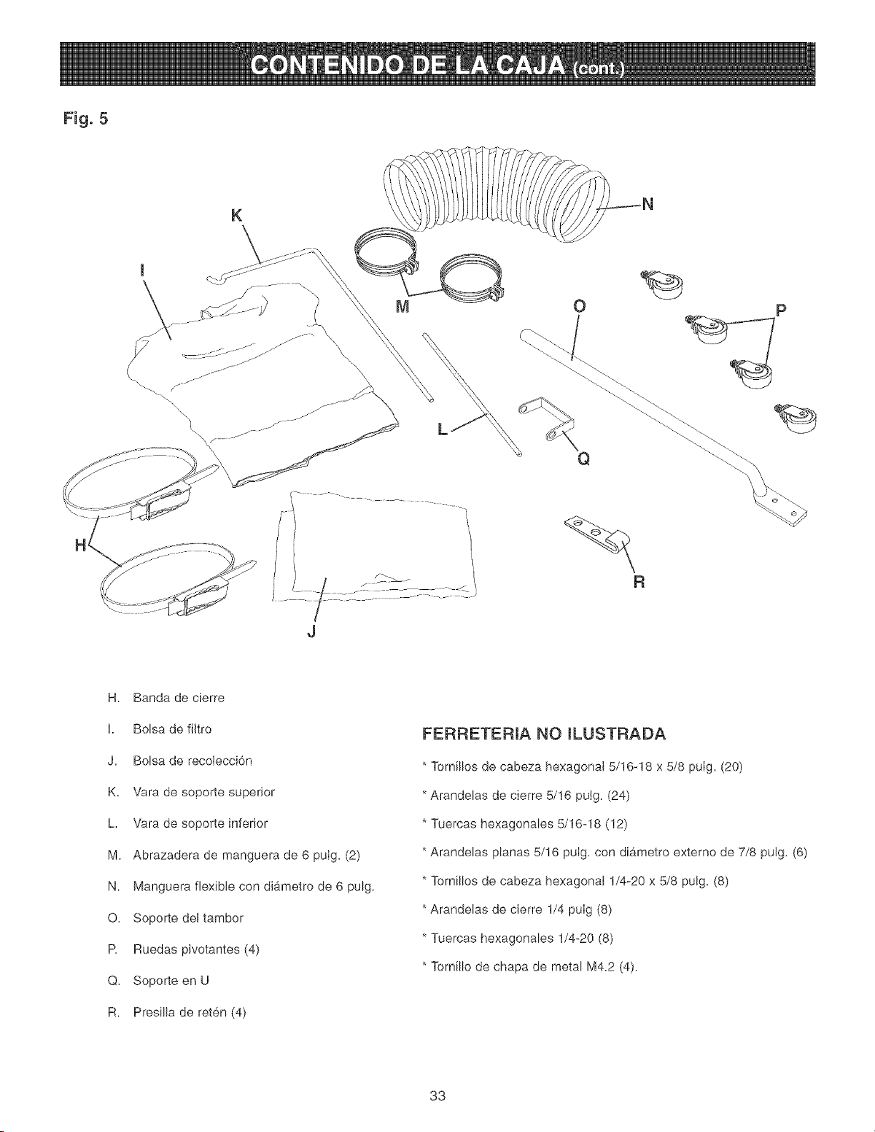
Fig. 5
K
O
R
H. Banda de cierre
I. Bolsa de filtro
J. Bolsa de recolecci6n
K. Vara de soporte superior
h Vara de soporte inferior
M. Abrazadera de manguera de 6 pulg. (2)
N. Manguera flexible con diametro de 6 pulg.
O. Soporte del tambor
R Ruedas pivotantes (4)
Q. Soporte en U
R. Presilla de reten (4)
FERRETERIA NO ILUSTRADA
* Tornillos de cabeza hexagonaI 5/16-18 x 5/8 puIg, (20)
* Arandelas de cierre 5/16 putg. (24)
* Tuercas hexagonales 5/16-18 (12)
* Arandelas planas 5/16 pulg. con diametro externo de 7/8 pulg. (6)
* Tornillos de cabeza hexagonal 1/4-20 x 5/8 pulg. (8)
* Arandelas de cierre 1/4 pulg (8)
* Tuercas hexagonales 1/4-20 (8)
* Tornillo de chapa de metal M4.2 (4).
33
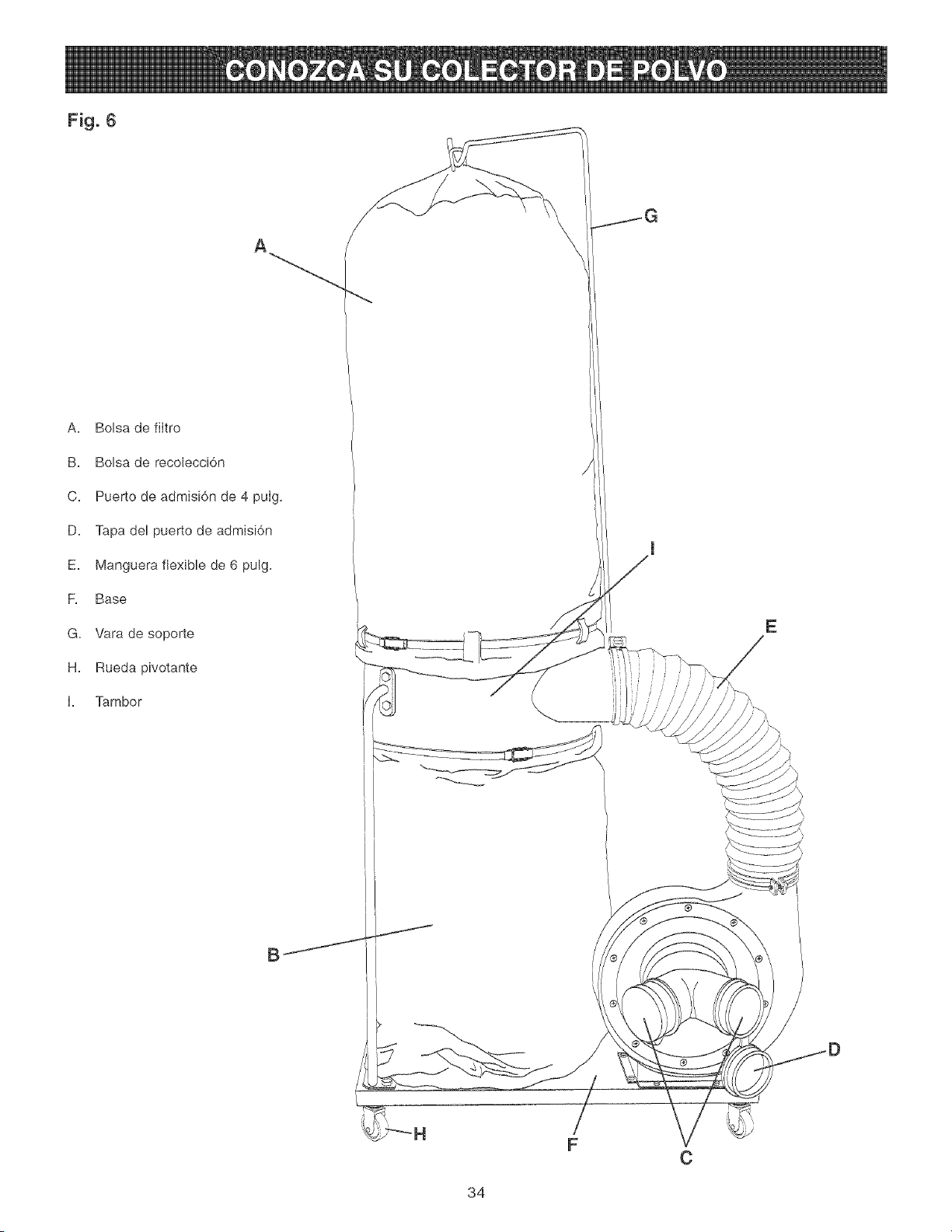
Fig. 6
A
A. Bolsa de filtro
B. Bolsa de recolecci6n
C. Puerto de admisi6n de 4 pulg.
D. Tapa del puerto de admisi6n
E. Manguera flexible de 6 pulg.
F. Base
G. Vara de soporte
H. Rueda pivotante
I. ]amber
E
F
C
34
1. NO inicie ei ensamblaje hasta que este seguro de que la
herramienta NO ESTA enchufada.
2. NO ensamble eI Colector de Polvo hasta que este seguro
de que el interrupter de energfa se encuentre en la posi-
ci6n de "APAGADO'.
3.
Para su propia seguridad, NO CONECTE Ia m_.quina a la
fuente de energfa hasta que la maquina se encuentre
completamente ensamblada y usted haya Ie[do y
entendido cabalmente el Manuel del Propietario.
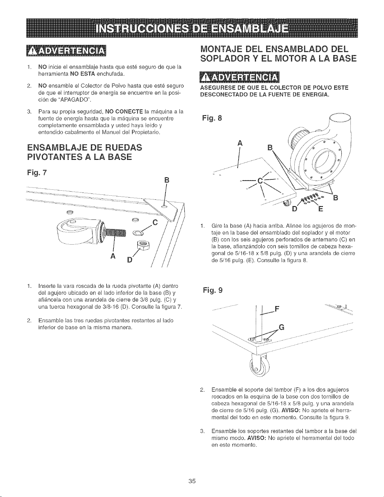
ENSAMBLAJE DE RUEDAS
PJVOTANTES A LA BASE
Fig. 7
B
A
MONTAJE DEL ENSAMBLADO BEL
SOPLADOR Y EL MOTOR A LA BASE
ASEGURESE DE QUE EL COLECTOR DE POLVO ESTE
DESCONECTADO DE LA FUENTE DE ENERGIA,
Fig. 8
A
1.
B
D E
Gire Ia base (A) hacia arriba. Alinee los agujeros de men-
taje en la base del ensamblado deI soplador y el motor
(B) con Ios seis agujeros perforados de antemano (C) en
la base, afianzb, ndolo con seis tornillos de cabeza hexa-
gonal de 5/16-18 x 5/8 pulg. (D) y una arandela de cierre
de 5/16 pulg. (E). Consulte la figura 8.
2.
Inserte la vara roscada de la rueda pivotante (A) dentro
deI agujero ubicado en et lade inferior de la base (B) y
afi&ncela con una arandela de cierre de 3/8 pulg. (C) y
una tuerca hexagonal de 3/8-16 (D). Consulte Ia figura 7.
Ensamble Ias tres ruedas pivotantes restantes al lade
inferior de base en la misma manera.
2.
3.
Fig. 9
Ensamble el soporte del tambor (F) a los dos agujeros
roscados en la esquina de la base con dos tornillos de
cabeza hexagonal de 5/16-18 x 5/8 pulg. y una arandeta
de cierre de 5/16 pulg. (G). AVISO: No apriete el herra-
mental del todo en este memento. Consulte Ia figura 9.
Ensamble Ios soportes restantes del tambor a Ia base deI
mismo mode. AWSO: No apriete el herramental del todo
en este memento.
35
\
L
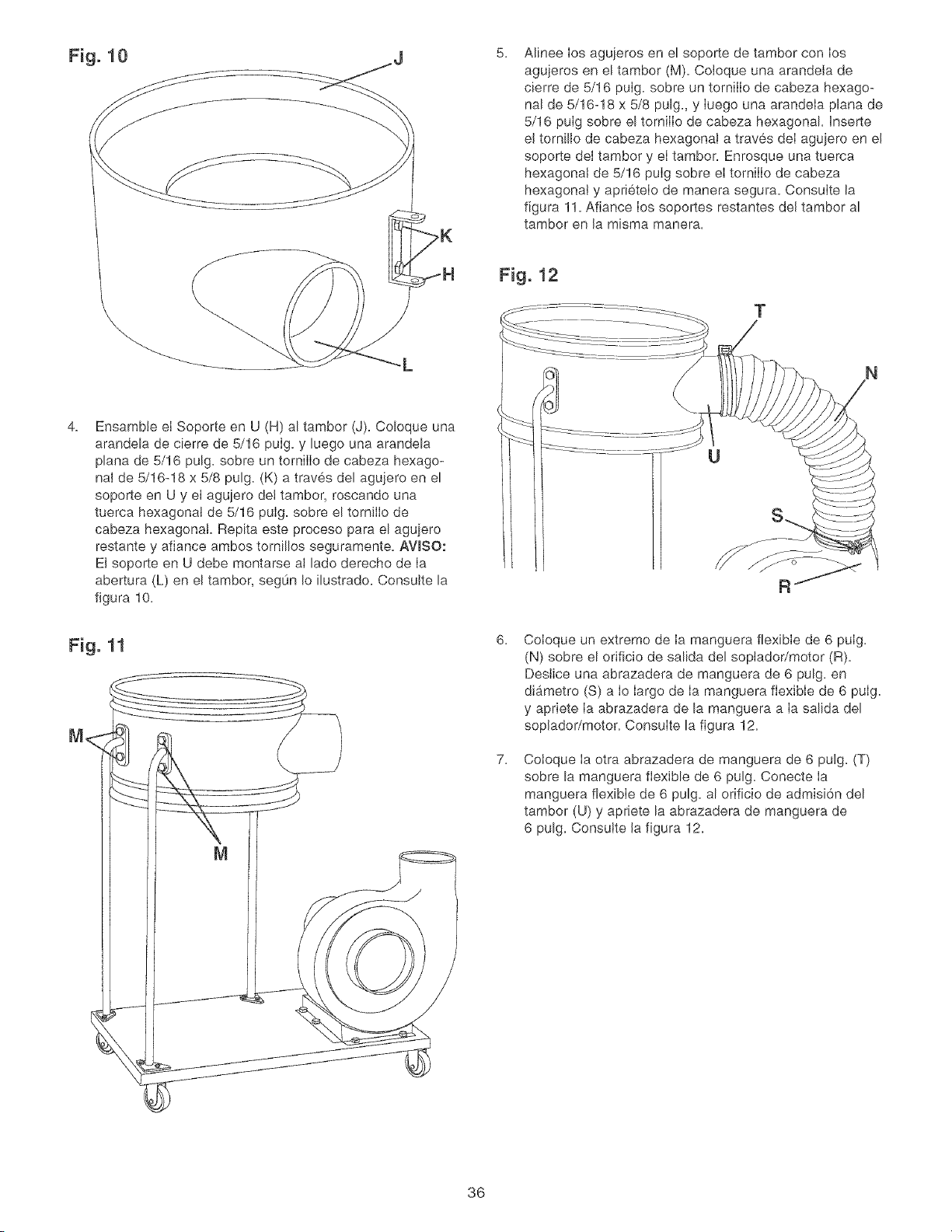
5.
Alinee los agujeros en el soporte de tambor con los
agujeros en el tambor (M). Coloque una arandela de
cierre de 5/16 pulg. sobre un tornilIo de cabeza hexago-
nal de 5/16-18 x 5/8 pulg, y Iuego una arandela plana de
5/16 pulg sobre el tornilIo de cabeza hexagonal. Inserte
el tornillo de cabeza hexagonal a traves deI agujero en el
soporte deI tambor y el tambor. Enrosque una tuerca
hexagonal de 5/16 pulg sobre el tornilIo de cabeza
hexagonal y aprietelo de manera segura. Consulte la
figura 11. Afiance los soportes restantes del tambor al
tambor en la misma manera.
Fig. 12
T
4.
Ensamble el Soporte en U (H) al tambor (J). Coloque una
arandela de cierre de 5/16 pulg. y luego una arandela
plana de 5/16 pulg. sobre un tornilIo de cabeza hexago-
nal de 5/16-18 x 5/8 pulg. (K) a traves del agujero en el
soporte en U y el agujero de! tambor, roscando una
tuerca hexagonal de 5/16 pulg. sobre el tornilIo de
cabeza hexagonal. Repita este proceso para el aguiero
restante y afiance ambos tornillos seguramente. AVlSO:
El soporte en U debe montarse al lado derecho de Ia
abertura (L) en el tambor, segOn Io ilustrado. Consutte la
figura 10.
Fig. 11
M_
6.
7.
U
Coloque un extreme de Ia manguera flexible de 6 pulg.
(N) sobre el orificio de salida del soplador/motor (R).
Deslice una abrazadera de manguera de 6 pulg. en
diametro (S) a Io largo de Ia manguera flexible de 6 pulg.
y apriete Ia abrazadera de la manguera a Ia salida del
soplador/motor. Consulte la figura 12.
Cotoque Ia otra abrazadera de manguera de 6 pulg. (T)
sobre la manguera flexible de 6 pulg. Conecte Ia
manguera flexible de 6 pulg. al orificio de admisi6n del
tambor (U) y apriete la abrazadera de manguera de
6 pulg. Consutte la figura 12.
36
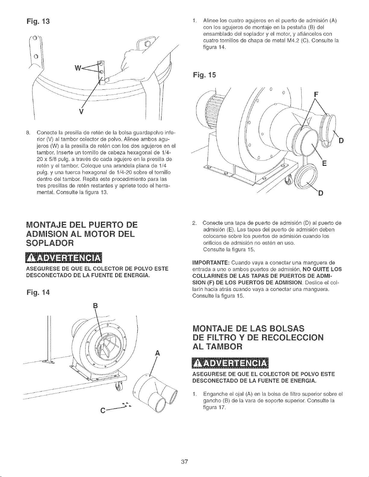
Fig. 13
V
1.
Alinee Ios cuatro agujeros en eI puerto de admisi6n (A)
con los agujeros de montaie en la pesta_a (B) del
ensamblado dei sopIador y el motor, y afiancelos con
cuatro torniJios de chapa de metal M4.2 (C). Consulte Ja
figura 14.
Fig. 15
0
0
8.
Conecte la presilIa de reten de Ia bolsa guardapoivo infe-
rior (V) al tambor coJector de poIvo. AIinee ambos agu-
jeros (W) a la presilIa de reten con los dos agujeros en el
tambon Inserte un tornillo de cabeza hexagonal de 1/4-
20 x 5/8 pulg. a traves de cada agujero en la presilla de
reten y el tambor. CoIoque una arandela pIana de 1/4
puIg. y una tuerca hexagonal de 1/4-20 sobre et tornillo
dentro det tambon Repita este procedimiento para las
tres presillas de reten restantes y apriete todo el herra-
mental. Consulte Ja figura 13.
D
MONTAJE DEL PUERTO DE
ADMJSJON AL MOTOR DEL
SOPLADOR
ASEGUFtESE DE QUE EL COLECTOR DE POLVO ESTE
DESCONECTADO DE LA FUENTE DE ENERGIAo
Fig. 14
B
2.
Conecte una tapa de puerto de admisi6n (D) al puerto de
admisi6n (E). Las tapas deI puerto de admisJ6n deben
colocarse sobre los puertos de admisi6n cuando los
orificios de admisi6n no esten en uso.
Consulte la figura 15.
tMPORTANTE: Cuando vaya a conectar una manguera de
entrada a uno o ambos puertos de admisi6n, NO QUITE LOS
COLLARINES DE LAS TAPAS DE PUERTOS DE ADMIo
SION (F) DE LOS PUERTOS DE ADMISJON, DeslJce eI col-
Jarfn hacia atr_s cuando vaya a conectar una manguera.
Consulte Ja figura 15.
A
MONTAJE DE LAS BOLSAS
DE FJLTRO Y DE RECOLECCJON
AL TAMBOR
ASEGURESE DE QUE EL COLECTOR DE POLVO ESTE
DESCONECTADO DE LA FUENTE DE ENERGIA,
1. Enganche el ojal (A) en la bolsa de filtro superior sobre el
gancho (B) de la vara de soporte superior. Consulte la
figura 17.
37
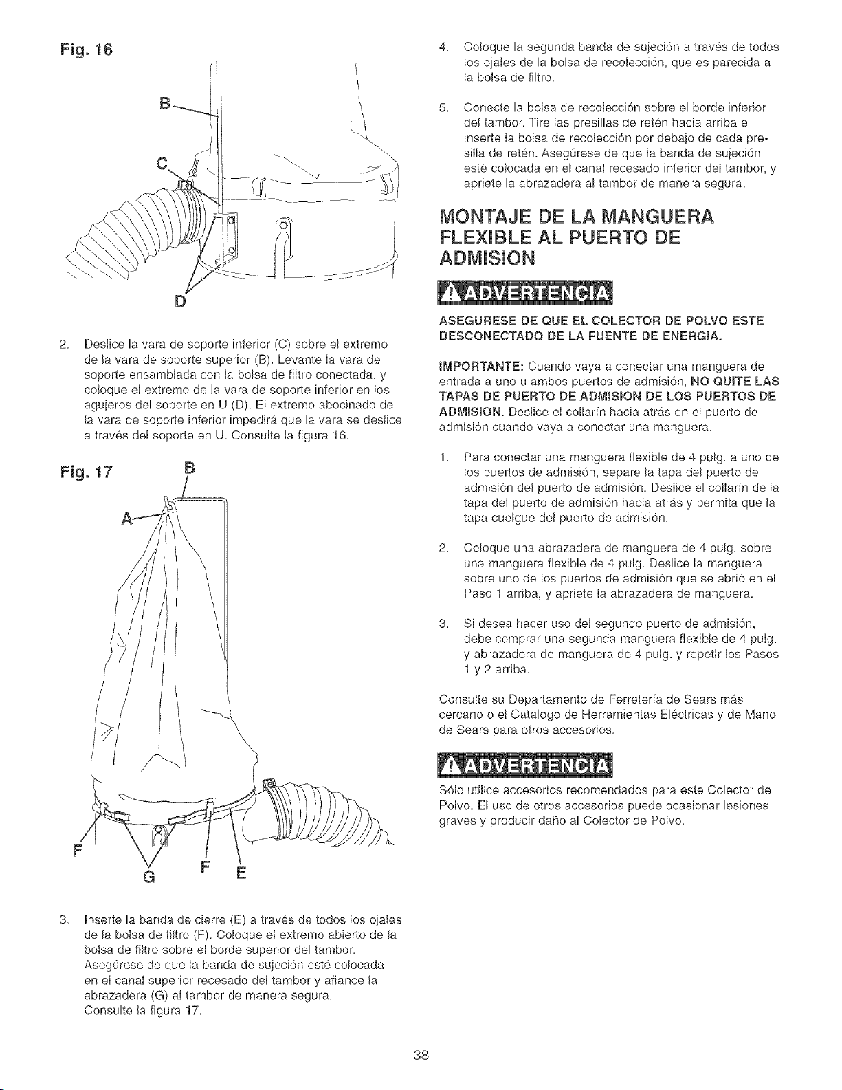
Fig. 16
4. Co!oque la segunda banda de suieci6n a traves de todos
los o]ales de la bolsa de recolecci6n, que es parecida a
la bolsa de filtro.
5. Conecte la bolsa de recolecci6n sobre el borde inferior
del tambor. Tire las presillas de reten hacia arriba e
[nserte Ia bolsa de recolecci6n per debajo de cada pre-
silla de reten. Asegurese de que Ia banda de sujeci6n
este colocada en el canal recesado inferior del tambor, y
apriete la abrazadera al tambor de manera segura.
MONTAJE DE LA IVIANGUERA
FLEXIBLE AL PUERTO DE
D
2.
Deslice la vara de soporte inferior (C) sobre el extremo
de la vara de soporte superior (B). Levante Ia vara de
soporte ensambtada con Ia bolsa de fiItro conectada, y
co!oque el extremo de Ia vara de soporte inferior en los
agujeros del soporte en U (D). El extremo abocinado de
la vara de soporte inferior impedira que la vara se deslice
a traves del soporte en U. Consulte Ja figura 16.
Fig. 17 B
ASEGURESE DE QUE EL COLECTOR DE POLVO ESTE
DESCONECTADO DE LA FUENTE DE ENERGIA,
tMPORTANTE: Cuando vaya a conectar una manguera de
entrada a uno u ambos puertos de admisi6n, NO QUITE LAS
TAPAS DE PUERTO DE ADMtSION DE LOS PUERTOS DE
ADMISlONo Deslice ei collar[n hacia atr&s en el puerto de
admisi6n cuando vaya a conectar una manguera.
1.
Para conectar una manguera flexible de 4 pulg. a uno de
los puertos de admisi6n, separe la tapa del puerto de
admisi6n dei puerto de admisi6n. Deslice el collar[n de la
tapa dei puerto de admisi6n hacia atrb,s y permita que la
tapa cuelgue dei puerto de admisi6n.
2.
Coloque una abrazadera de manguera de 4 pulg. sobre
una manguera flexible de 4 pulg. Deslice Ia manguera
sobre uno de los puertos de admisi6n que se abri6 en el
Paso 1 arriba, y apriete la abrazadera de manguera.
3.
Si desea hacer use deJ segundo puerto de admisi6n,
debe comprar una segunda manguera flexible de 4 pulg.
y abrazadera de manguera de 4 puIg. y repetir los Pasos
1 y 2 arriba.
Consulte su Departamento de Ferreteria de Sears m#_s
cercano o el Catalogo de Herramientas Electricas y de Mane
de Sears para otros accesorios.
S61o utilice accesorios recomendados para este Colector de
Polvo. El use de otros accesorios puede ocasionar lesiones
graves y producir daBo al Colector de Polvo.
G F E
3.
Inserte la banda de cierre (E) a traves de todos los oiales
de la boIsa de filtro (F). Coloque el extreme abierto de la
bolsa de filtro sobre el borde superior del tambor.
AsegOrese de que Ia banda de sujeci6n este colocada
en el canal superior recesado deI tambor y afiance la
abrazadera (G) aI tambor de manera segura.
Consulte la figura 17.
38
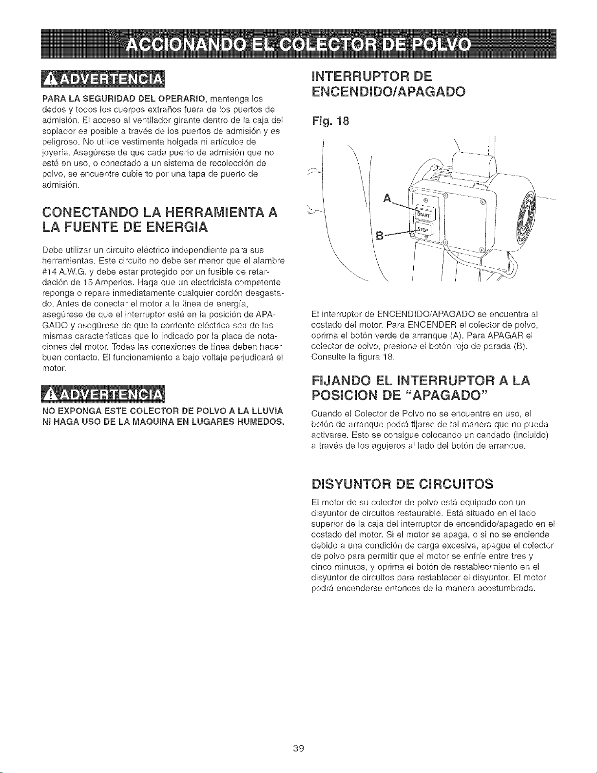
PARA LA SEGURIDAD DEL OPERARIO, mantenga los
dedos y todos los cuerpos extrahos fuera de los puertos de
admisi6n. Et acceso al ventilador girante dentro de la caia deI
sopJador es posible a traves de Ios puertos de admisi6n y es
peligroso. No utilice vestimenta holgada ni artfcuJos de
joyerfa. Asegurese de que cada puerto de admisi6n que no
este en uso, o conectado a un sistema de recolecci6n de
polvo, se encuentre cubierto por una tapa de puerto de
admisi6n.
CONECTANDO LA HERRAMJENTA A
LA FUENTE DE ENERGJA
Debe utiIizar un circuito eI6ctrico independiente para sus
herramientas. Este circuito no debe ser menor que el alambre
#14 A.W.G. y debe estar protegido per un fusible de retar-
daci6n de 15 Ampenos. Haga que un eiectricista competente
reponga o repare inmediatamente cualquier cord6n desgasta-
do. Antes de conectar el motor a la linea de energfa,
asegurese de que el interruptor este en Ia posici6n de APA-
GADO y asegurese de que Ia corriente el6ctrica sea de Ias
mismas caracter[sticas que Io indicado per Ia placa de nota-
ciones del motor. Todas las conexiones de I[nea deben hacer
buen contacto. El funcionamiento a baio voltaie periudicar_i eJ
motor.
NO EXPONGA ESTE COLECTOR DE POLVO A LA LLUWA
N_ HAGA USO DE LA MAQU_NA EN LUGARES HUMEDOS.
JNTERRUPTOR DE
ENCENDJDO/APAGADO
Fig. 18
\
\\
\
El interruptor de ENCENDDO/APAGADO se encuentra aJ
costado de! motor. Para ENCENDER el coJector de polvo,
oprima el bot6n verde de arranque (A). Para APAGAR eJ
colector de poJvo, presione eJ bot6n rojo de parada (B).
Consulte Ja figura 18.
NJANDO EL JNTERRUPTOR A LA
POSJCJON DE "APAGADO"
Cuando el Colector de Polvo no se encuentre en uso, el
bot6n de arranque pedro1fijarse de tal manera que no pueda
activarse. Esto se consigue colocando un candado (incluido)
a traves de Jos agujeros al Jade del bot6n de arranque.
DJSYUNTOR DE CJRCUJTOS
El motor de su cotector de polvo esta equipado con un
disyuntor de circuitos restaurable. Esta situado en el lade
superior de Ia caja de! interrupter de encendido/apagado en eJ
costado deI motor. Si e! motor se apaga, o si no se enciende
debido a una condJci6n de carga excesiva, apague el colector
de polvo para permitir que el motor se enfrfe entre tres y
cinco minutes, y oprima el bot6n de restablecimiento en el
disyuntor de circuitos para restablecer el disyuntor. El motor
pedro1 encenderse entonces de Ja manera acostumbrada.
39
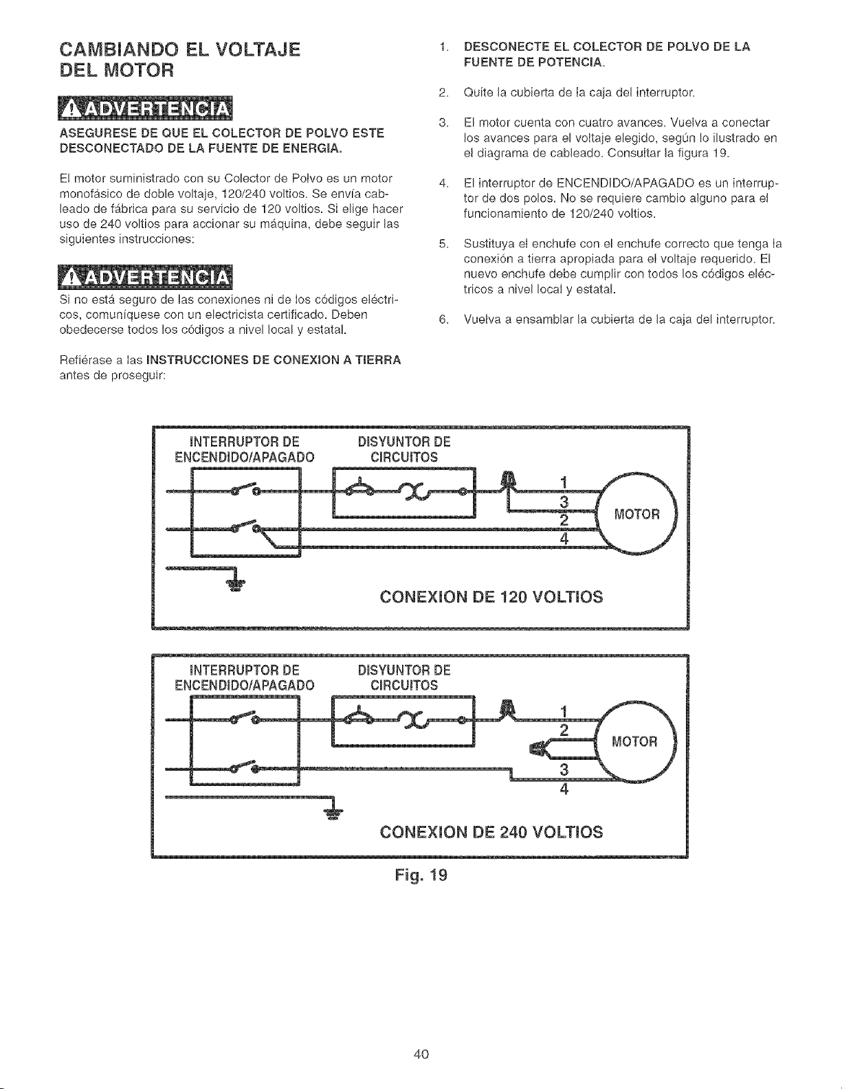
CAMBJANDO EL VOLTAJE
DEL MOTOR
ASEGURESE DE QUE EL COLECTOR DE POLVO ESTE
DESCONECTADO DE LA FUENTE DE ENERGIA.
E! motor suministrado con su Colector de Polvo es un motor
monofasico de doble voltaje, 120/240 vokios. Se env[a cab-
leado de fabrica para su servicio de 120 voltios. Si elige hacer
uso de 240 voltios para accionar su maquina, debe seguir las
siguientes instrucciones:
Si no esta seguro de las conexiones ni de los c6digos etectri-
cos, comunfquese con un electricista certificado. Deben
obedecerse todos los c6digos a nivel local y estataL
Refierase a Ias INSTRUCCIONES DE CONEXtON A TtERRA
antes de proseguir:
1. DESCONECTE EL COLECTOR DE POLVO DE LA
FUENTE DE POTENCIA.
2. Quite la cubierta de Ia caia del interruptor.
3. El motor cuenta con cuatro avarices. Vuelva a conectar
los avarices para el voltaje elegido, segun Io ilustrado en
el diagrama de cableado. Consultar la figura 19.
4. El interruptor de ENCENDDQ/APAGADQ es un interrup-
tor de dos polos. No se requiere cambio alguno para el
funcionamiento de 120/240 voltios.
5.
Sustituya el enchufe con el enchufe correcto que tenga Ia
conexi6n a tierra apropiada para el voltaje requerido. El
nuevo enchufe debe cumplir con todos los c6digos elec-
tricos a nivel local y estataL
6. Vuelva a ensamblar la cubierta de la caja del interruptor.
INTERRUPTOR DE DISYUNTOR DE
ENCENDtDO/APAGADO CIRCUITOS
1
4
CONEXION DE 120 VOLTIOS
INTERRUPTOR DE DISYUNTOR DE
ENCENDtDO/APAGADO CIRCUITOS
1
3
4
CONEXION DE 240 VOLTIOS
EEiE i
Fig. 19
4O
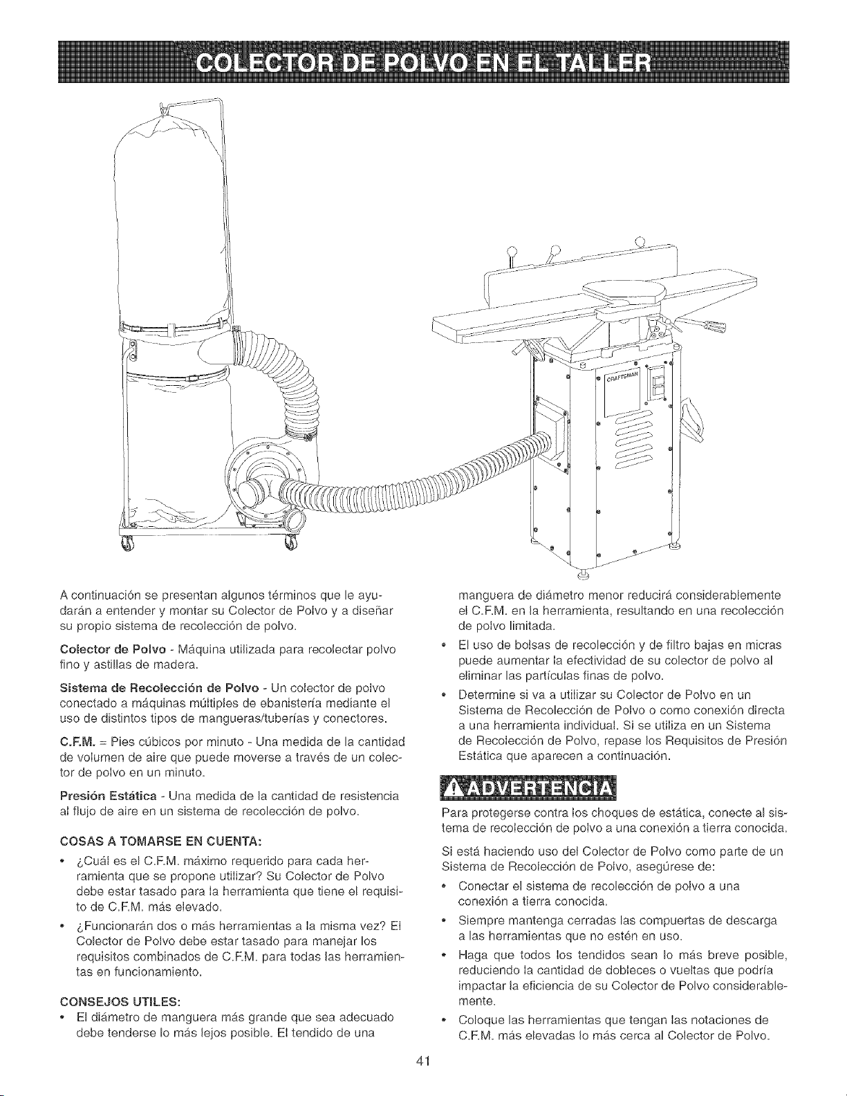
A continuaci6n se presentan atgunos t@minos que le ayu-
daran a entender y montar su Colector de Poivo y a dise_ar
su propio sistema de recoIecci6n de polvo.
¢oBeotor de Polvo - Maquina utiJizada para recolectar poJvo
fine y astillas de madera.
Sistema de Recomecci6n de Poivo - Un coiector de polvo
conectado a maquinas muItipies de ebanisterfa mediante el
use de distintos tipos de mangueras/tuberfas y conectores.
CoRMo = Pies cObicos per minute - Una medida de la cantidad
de voIumen de aire que puede moverse a traves de un colec-
tor de polvo en un minute.
Presi6n Estatica - Una medida de la cantidad de resistencia
aI fiujo de aire en un sistema de recolecci6n de polvo.
COSAS A TOMARSE EN CUENTA:
. &Cu&J es el C.F.M. mgximo requerido para cada her-
ramienta que se propone utiiizar? Su Colector de Polvo
debe estar tasado para ia herramienta que tiene el requisi-
to de C.RM. mas eievado.
o LFuncionaran dos o mas herramientas a ia misma vez? El
Colector de Polvo debe estar tasado para manejar los
requisitos combinados de C.RM. para todas las herramien-
tas en funcionamiento.
CONSEJOS UTILES:
El di_.metro de manguera rags grande que sea adecuado
debe tenderse Io mas Jejos posible. El tendido de una
manguera de diametro menor reducir_, considerabiemente
el C.RM. en la herramienta, resultando en una recolecci6n
de polvo limitada.
El use de boisas de recolecci6n y de filtro bajas en micras
puede aumentar Ia efectividad de su colector de polvo al
eJiminar las partfcuIas finas de poIvo.
Determine siva a utiIizar su Colector de Polvo en un
Sistema de Recolecci6n de Polvo o como conexi6n directa
a una herramienta individual. Si se utiIiza en un Sistema
de Recoiecci6n de Polvo, repase los Requisites de Presi6n
Estatica que aparecen a continuaci6n.
Para protegerse contra los choques de estatica, conecte al sis-
tema de recoIecci6n de polvo a una conexi6n a tierra conocida.
Siesta haciendo uso deJ Colector de Poivo come parte de un
Sistema de Recolecci6n de Poivo, aseg0rese de:
o Conectar el sistema de recolecci6n de poivo a una
conexi6n a tierra conocida.
o Siempre mantenga cerradas las compuertas de descarga
alas herramientas que no esten en uso.
Haga que todos ios tendidos sean Io m_.s breve posible,
reduciendo Ia cantidad de dobIeces o vueJtas que podrfa
impactar Jaeficiencia de su Colector de Polvo considerabJe-
mente.
o Coloque las herramJentas que tengan Ias notaciones de
C.RM. mas elevadas Jo mas cerca al CoJector de Polvo.
41
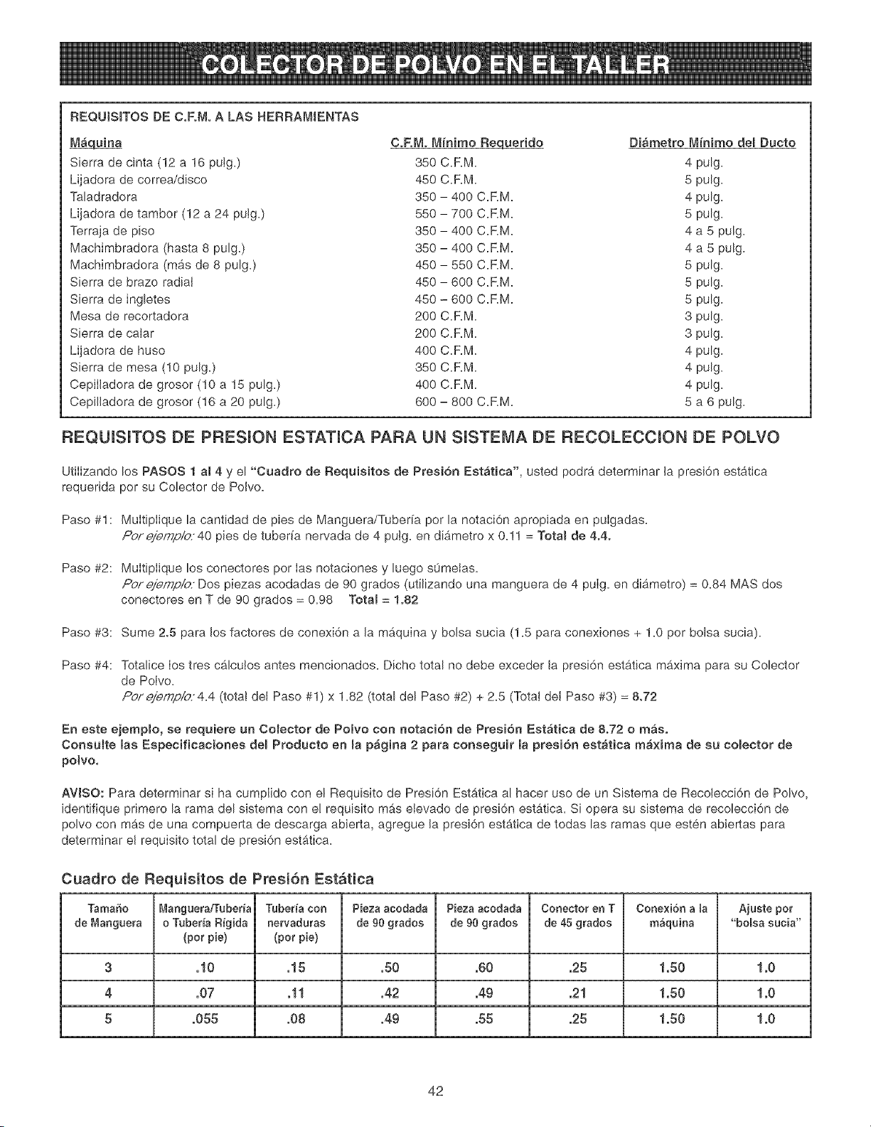
REQUJSITOS DE C.FoMoA LAS HERRAMIENTAS
_uina
Sierra de cinta (12 a 16 puig,)
Lijadora de correa/disco
Taladradora
Lijadora de tambor (12 a 24 putg,)
Terraja de piso
Machimbradora (hasta 8 pulg,)
Machimbradora (mas de 8 pulg,)
Sierra de brazo radiat
Sierra de ingletes
Mesa de recortadora
Sierra de calar
Lijadora de huso
Sierra de mesa (10 pulg,)
Cepilladora de grosor (10 a 15 pulg.)
Cepilladora de grosor (16 a 20 pulg,)
C.RM. M{nimo Requerido Diametro M_nimo del Ducto
350 CaRM, 4 pulg,
450 CaRM, 5 pulg,
350 - 400 CaRM. 4 pulg,
550 - 700 CaRM, 5 pulg,
350 - 400 CaRM. 4 a 5 pulg.
350 - 400 C.RM. 4 a 5 pulg,
450 - 550 CaRM, 5 pulg,
450 - 600 C.RM, 5 pulg,
450 - 600 CaRM, 5 pulg,
200 CaRM, 3 pulg,
200 CaRM, 3 pulg,
400 CaRM, 4 pulg,
350 CaRM, 4 pulg.
400 CaRM, 4 pulg,
600 - 800 CaRM, 5 a 6 pulg,
REQUISUTOS DE PRESUON ESTATICA PARA UN SUSTEMA DE RECOLECCION DE POLVO
Utiiizando los PASOS 1 al 4 y el °'Cuadro de Requisitoe de Presi6n Estatica', usted podra determinar la presi6n estatica
requerida per su Colector de Polvo,
Paso #1 : Multiplique la cantidad de pies de Manguera/Tuber[a per la notaci6n apropiada en pulgadas,
Pof #idJ/77p/O" 40 pies de tuber[a nervada de 4 putg, en diametro x 0,11 = Totam de 4.4.
Paso #2: Multiplique los conectores per Ias notaciones y luego s0metas,
Pof e/emp/o Dos piezas acodadas de 90 grades (utilizando una manguera de 4 pulg, en diametro) = 0,84 MAS dos
conectores en T de 90 grades = 0,98 Total = 1.82
Paso #3: Sume 2.5 para los factores de conexi6n a lamb, quina y bolsa sucia (1,5 para conexiones + 1,0 por bolsa sucia),
Paso #4: Totalice Ios tres cbJcutos antes mencionados, Dicho total no debe exceder la presi6n estatica mb,xima para su Colector
de Polvo,
Po/'eiemp/o4,4 (totat del Paso #1) x 1,82 (total del Paso #2) + 2,5 (Total del Paso #3) = 8.72
En este ejempmo, ee requiere un Co_ector de Polvo con notacion de Presion Eet_tica de 8.72 o mas.
Consu_te las Especificaciones demProdueto en map_gina 2 para conseguir la presi6n estatica ma×ima de su comector de
potvo.
AWSO: Para determinar si ha cumplido con el Requisito de Presi6n Estatica al hacer uso de un Sistema de Recolecci6n de Polvo,
identifique pdmero la rama del sistema con e! requisite mas etevado de presi6n estatica, Si opera su sistema de recolecci6n de
polvo con mas de una compuerta de descarga abierta, agregue la presi6n estatica de todas las ramas que esten abiertas para
determinar el requisite total de presi6n estg,tica,
Cuadro de Requisitos de Presi6n Estatica
Tama_o Manguetafl'ubeda Tuber_acon Pieza acodada Piezaacodada Conector en T Cone×i6n a la Ajuste pot
de Manguera o Tubeda Rigida nervaduras de 90 grados de 90 grados de 45 gtados m_quina "bolsa sucia"
(pot pie) (pot pie)
3 .10 .15 .50 .60 .25 1.50 1.0
4 .07 .11 .42 .49 .21 1.50 1.0
5 .055 .08 .49 .55 .25 1.50 1.0
42
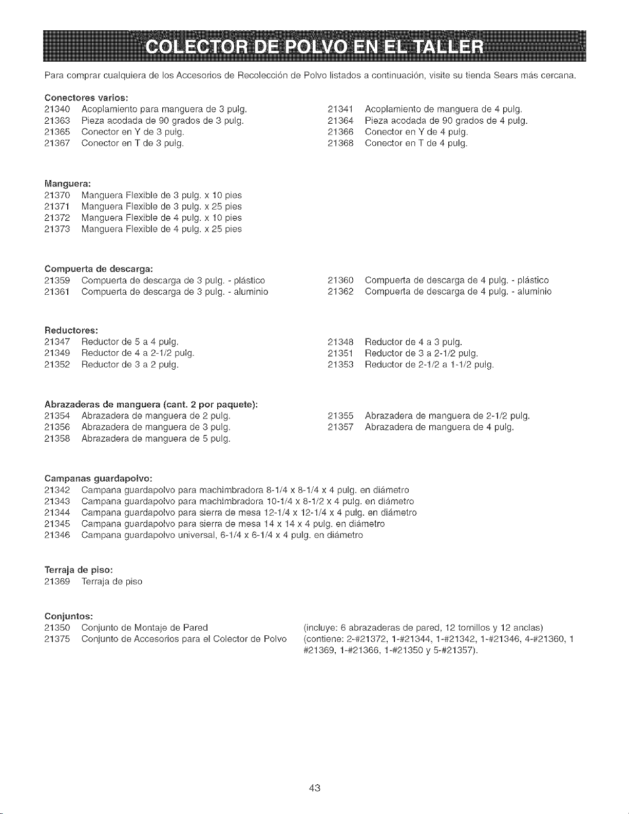
Para comprar cualquiera de los Accesorios de Recolecci6n de Polvo listados a continuaci6n, visite su tienda Sears mas cercana.
Conectores varios:
21340 AcopIamiento para manguera de 3 puIg. 21341
21363 Pieza acodada de 90 grades de 3 pulg. 21364
21365 Conector en Y de 3 puIg. 21366
21367 Conector en T de 3 puIg. 21368
Acoplamiento de manguera de 4 pulg.
Pieza acodada de 90 grados de 4 puIg.
Conector en Y de 4 puIg.
Conector en T de 4 pulg.
Manguera:
21370 Manguera Flexible de 3 pulg. x 10 pies
21371 Manguera Flexible de 3 pulg. x 25 pies
21372 Manguera Flexible de 4 pulg. x 10 pies
21373 Manguera Flexible de 4 pulg. x 25 pies
Compuerta de descarga:
21359 Compuerta de descarga de 3 pulg. - plastico
21361 Compuerta de descarga de 3 pulg. - aluminio
21360 Compuerta de descarga de 4 pulg. - plgstico
21362 Compuerta de descarga de 4 pulg. - aluminio
Reductores:
21347 Reductor de 5 a 4 puIg.
21349 Reductor de 4 a 2-1/2 puIg.
21352 Reductor de 3 a 2 puIg.
21348
21351
21353
Reductor de 4 a 3 pulg.
Reductor de 3 a 2-1/2 putg.
Reductor de 2-1/2 a 1-1/2 puIg.
Abrazaderas de manguera (cant. 2 per paquete):
21354 Abrazadera de manguera de 2 pulg.
21356 Abrazadera de manguera de 3 pulg.
21358 Abrazadera de manguera de 5 pulg.
21355
21357
Abrazadera de manguera de 2-1/2 pulg.
Abrazadera de manguera de 4 puIg.
Campanas guardapolvo:
21342 Campana guardapolvo para machimbradora 8-1/4 x 8-1/4 x 4 pulg. en diametro
21343 Campana guardapolvo para machimbradora 10-1/4 x 8-1/2 x 4 puIg. en diametro
21344 Campana guardapoIvo para sierra de mesa 12-1/4 x 12-1/4 x 4 puIg. en diametro
21345 Campana guardapolvo para sierra de mesa 14 x 14 x 4 pulg. en diametro
21346 Campana guardapolvo universal, 6-1/4 x 6-1/4 x 4 pulg. en diametro
Terraja de piso:
21369 Terraja de piso
Conjuntos:
21350 Conjunto de Montaie de Pared
21375 Conjunto de Accesorios para el Colector de Polvo
(incluye: 6 abrazaderas de pared, 12 tornillos y 12 anclas)
(contiene: 2-#21372, 1-#21344, 1-#21342, 1-#21346, 4-#21360, 1
#21369, 1-#21366, 1-#21350 y 5-#21357).
43
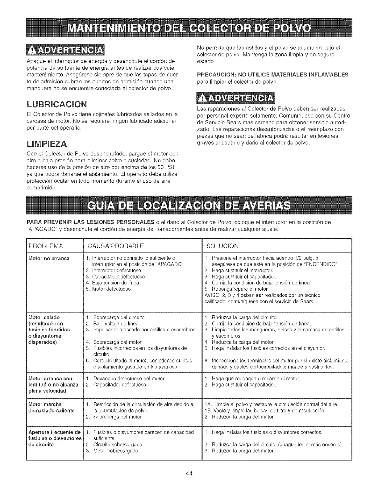
Apague el interruptor de energfa y desenchufe el cord6n de
potencia de su fuente de energfa antes de realizar cualquier
mantenimiento. Asegurese siempre de que Ias tapas de puer-
to de admisi6n cubran los puertos de admisi6n cuando una
manguera no se encuentre conectada al cobctor de polvo.
No permita que Ias astiiIas y el polvo se acumulen bajo el
coIector de polvo. Mantenga la zona limpia yen seguro
estado.
PRECAUC_ON: NO UT_UCE MATER_ALES 8NFLAMABLES
para limpiar el cobctor de polvo.
El Colector de Polvo tiene cojinetes lubricados seiIados en la
carcasa de motor. No se requiere ning0n lubricado adicionat
por parte del operario.
Con el Cobctor de Potvo desenchufado, purgue el motor con
aire a baja presi6n para eliminar polvo o sucbdad. No debe
hacerse uso de Ia presi6n de aire por encima de los 50 PSi,
ya que podr& daharse el aisiamiento. El operario debe utilizar
protecci6n ocular en todo momento durante el uso de aire
comprimido.
Las reparaciones al Colector de Polvo deben ser realizadas
por personal experto solamente. Comunfquese con su Centro
de Servicio Sears mas cercano para obtener servicio autori-
zado. Las reparaciones desautorizadas o el reemplazo con
piezas que no sean de fabrica podr9 resuttar en bsiones
graves al usuario y daho al cobctor de polvo.
PARA PREVENJR LAS LESIONES PERSONALES o el daSo al Coiector de Polvo, coloque ei interruptor en la posici6n de
"APAGADO" y desenchufe el cord6n de energfa del tomacorrientes antes de realizar cualquier ajuste.
PROBLEMA CAUSA PROBABLE SOLUCION
_,_otor no arranca
Motor caRado
(resamtando en
fasiMes fundidos
o disyuntores
disparados)
Motor arl'anoa con
meatitud o no amcanza
pbaa vemocidad
Motor marcha
demasiado camiente
Apertura frecuente de
fusiMes o disyuntores
de circuito
1. Interruptor no oprimido Io suficiente o
interruptor en el posici6n de "APAGADO"
2. Interruptor defectuoso
3. Capacitador defectuoso
4. Baja tensi6n de Ifnea
5. Motor defectuoso
2.
3.
2.
1.
2.
3.
1. Presione el interruptor hacia adentro 1/2 pulg. o
asegurese de que este an la posici6n de 'ENCENDiDO".
2. Haga sustituir e! interruptor.
3. Haga sustituir e! capacitador.
4. Corrija la condiei6n de baja tensi6n de linea
5. Reponga/repare el motor
AVISO: 2, 3 y 4 deben ser realizados por un tecnico
califieado; comuniquese con el servicio de Sears.
Sobrecarga del circuito 1.
Bajo voltaje de linea 2.
Impulsador atascado por asfillas o escombros 3.
Sobrecarga del motor 4,
Fusibles incorrectos en los disyuntores de 5.
circuito
Cortocircuitado el motor; conexiones sueltas 6.
o aislamiento gastado an los avances
Devanado defectuoso del motor. 1.
Capacitador defectuoso 2.
Restrieei6n de la eireulaei6n de aire debido a
la aeumulaci6n de polvo
Sobrecarga del motor
Fusibles o disyuntores earecen de eapacidad
suficiente
Circuito sobrecargado
Motor sobrecargado
Reduzca la carga de! circuito.
Corrija la condici6n de baja tensi6n de linea.
Limpie todas las mangueras, bolsas y la carcasa de astillas
y escombros.
Reduzca la carga de! motor.
Haga instalar los fusibles correctos en el disyuntor.
Inspeccione los terminabs del motor por si existe aislamiento
daflado y cables cortocircuitados; mande a sustituirlos.
Haga que repongan o reparen el motor.
Haga sustituir e! capacitador.
1A. Limpie e! polvo y restaure la circulaci6n normal del aire.
lB. Vacfe y limpie las bolsas de filtro y de recolecci6n.
2. Reduzca la carga de! motor.
1. Haga instalar los fusibles o disyuntores correctos.
2. Reduzca la carga de! circuito (apague los demAs enseres).
3. Reduzca la carga de! motor.
44
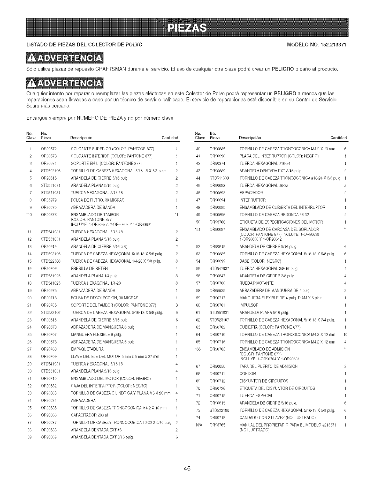
MSTADO DE PIEZAS DEL COLECTOR DE POLVO _,'IODELO NO. 152.213371
SCIo utilice piezas de repuesto CRAFTSMAN durante e! servicio. E! use de cualquier otra pieza podr& crear un PEUGRO o daSo al producto.
Cualquier intento per reparar o reemplazar las piezas el@tricas en este Colector de PoIvo podra representar un PEMGRO a menos que las
reparaciones sean Ilevadas a cabo por un t@nico de servicio calificado, El servicio de reparaciones esta disponible en su Centre de Servicio
Sears mas cercano,
Encargue siempre pot NUMERO DE PIEZA y no pot numero clave.
No. No. No. No.
Clave Pieza DescripciCn Cantidad Clave Pieza
1 OR90672 DOLGANTE SUPERIOR (COLOR: PANTONE 877) 1 40 OR90685
2 OR90673 COLGANTE INFERIOR (COLOR: PANTONE 877) 1 41 OR90690
3 OR90674 SOPORTE EN U (COLOR: PANTONE877) 1 42 OR90374
4 STD528106 TORNILLO DECABEZA HEXAGONAL5/16-18 X 5/8 pulg. 2 43 OR90689
5 OR90615 ARANDELA DECIERRE 5/16 pulg, 2 44 8TD511003
6 8TD551031 ARANDELA PLANA5/16 pulg. 2 45 OR90692
7 8TD541031 TUEROA HEXAGONAL 5/16-18 2 46 OR90693
8 OR65979 BOLSA DE FILTRO,80 MICRAS 1 47 OR90694
9 OR90675 ABRAZADERA DE BANDA 1 48 OR90695
"10 OR90676 ENSAMBLADO DE TAMBOR '1 49 OR90696
(COLOR: PANTONE877
50 OR93766
INOLUYE: 1-OR90677,2-OR90608 Y 1-OR90601
'51 OR90697
11 8TD541031 TUERCA HEXAGONAL5/16-18 2
12 STD551031 ARANDELA PLANA5/16 pulg. 2
13 0R90615 ARANDELA DECIERRE 5/16 pulg, 2 52 0R90615
14 STD523106 TUERCA DE OABEZAHEXAGONAL 5/16-18 X 5/8 pulg, 2 53 0R90635
15 STD522506 TUERCA DE CABEZA HEXAGONAL 1/4-20 X 5/8 pulg. 8 54 0R90699
16 0R90706 PRESILLA DE RETEN 4 55 STD541037
17 STD551025 ARANDELA PLANA 1/4pulg, 8 56 0R90647
18 STD541025 TUERCA HEXAGONAL 1/4-20 8 57 0R90700
19 0R90675 ABRAZADERA DE BANDA 1 58 0R65935
20 0R90713 BOLSA DE RECOLECCION,30 MICRAS 1 59 0R90717
21 0R90705 SOPORTE DELTAMBOR (COLOR: PANTONE 877) 3 60 0R90701
22 STD523106 TUERCA DE CABEZA HEXAGONAL 5/16-18 X 5/8 pulg, 6 61 STD551031
28 0R90615 ARANDELA DEOlERRE 5/16 pulg, 6 62 STD523107
24 0R90678 ABRAZADERA DE MANGUERA6 pulg, 1 63 0R90702
25 0R90707 MANGUERA FLEXIBLE 6 pulg. 1 64 0R90716
26 0R90678 ABRAZADERA DE MANGUERA6 pulg, 1 85 0R90716
27 0R90708 EMPAQUETADURA 1 *66 0R90703
28 0R90709 LLAVE DEL EJE DEL MOTOR 5 mmx 5 mmx 27 mm 1
29 STD541031 TUEROA HEXAGONAL5/16-18 4
67 0R90850
30 STD551031 ARANDELA PLANA5/16 pulg. 4
68 0R90711
31 0R90710 ENSAMBLADO DEL MOTOR (COLOR: NEGRO) 1
69 0R90712
32 0R90682 CAJA DEL INTERRUPTOR(COLOR: NEGRO) 1
70 0R90726
33 0R90683 TORNILLO DE CABEZA CILINDRIOA Y PLANA M5 X 20 mm 4
71 0R90715
34 0R90684 ABRAZADERA 1
72 0R90615
35 0R90685 TORNILLO DE CABEZA TRONCOCONICA M4,2 X 10 mm 1
73 STD523106
36 0R90686 CAPACITADOR200 uf 1
74 0R90718
37 0R90687 TORNILLO DE CABEZA TRONCOCONICA #6-32 X 5/16 pulg, 2
N/A 0R93765
38 0R90688 ARANDELA DENTADAEXT #6 2
39 0R90689 ARANDELA DENTADAEXT 3/16 pulg, 6
DesnripniCn Cantidad
TORNILLO DE CABEZATRONCOOONICA M4,2 X 10 mm 6
PLAOA DEL INTERRUPTOR (COLOR: NEGRO) 1
TUERCA HEXAGONAL #10-24 1
ARANDELADENTADA EXT 3/16 pulg. 2
TORNILLO DE OABEZA TRONOOCONICA #10-24 X 3/8 pulg. 1
TUERCA HEXAGONAL #6-32 2
ESPACIADOR 2
INTERRUPTOR 1
ENSAMBLADO DE CUBERTA DEL INTERRUPTOR 1
TORNILLO DE OABEZA REDONDA #6-32 2
ETIQUETA DE ESPECIFIOACIONES DEL MOTOR 1
ENSAMBLADO DE OARCASA DEL SOPLADOR '1
(COLOR: PANTONE877)INCLUYE: 1-0R90698,
1-0R90600 Y 1-0R90612
ARANDELA DE CIERRE 5/16 pulg. 6
TORNILLO DE CABEZA HEXAGONAL5/16-18 X 5/8 pulg. 6
BASE (COLOR: NEGRO) 1
TUERCA HEXAGONAL 3/8-16 pulg, 4
ARANDELADE CIERRE 8/8 pulg. 4
RUEDA PIVOTANTE 4
ABRAZADERA DE MANGUERA DE 4 pulg. 2
MANGUERA FLEXIBLE DE 4 pulg, DIAIvl X 6 pies 1
IMPULSOR 1
ARANDELA PLANA5/16 pulg. 1
TORNILLO DE OABEZA HEXAGONAL 5/16-18 X 3/4 pulg. 1
CUBIERTA(COLOR: PANTONE877) 1
TORNILLO DE OABEZATRONOOCONICA M4,2 X 12 mm 10
TORNILLO DE CABEZATRONCOCONICA M4,2 X 12 mm 4
ENSAMBLADO DEADMISION '1
(COLOR: PANTONE877)
INCLUYE: 1-OR90704 Y 1-OR90601
TAPA DEL PUERTO DE ADMISION 2
CORDON 1
DISYUNTOR DE CIRCUITOS 1
ETIQUETA DEL DISYUNTOR DECIRCUITOS 1
TUERCA ESPECIAL 1
ARANDELADE DIERRE 5/16 pulg. 6
TORNILLO DE OABEZA HEXAGONAL 5/16-18 X 5/8 pulg. 6
CANDADO DON 2 LLAVES(NO ILUSTRADO} 1
MANUAL DEL PROPIETARIO PARA EL MODELO #213371 1
(NO ILUSTRADO)
45
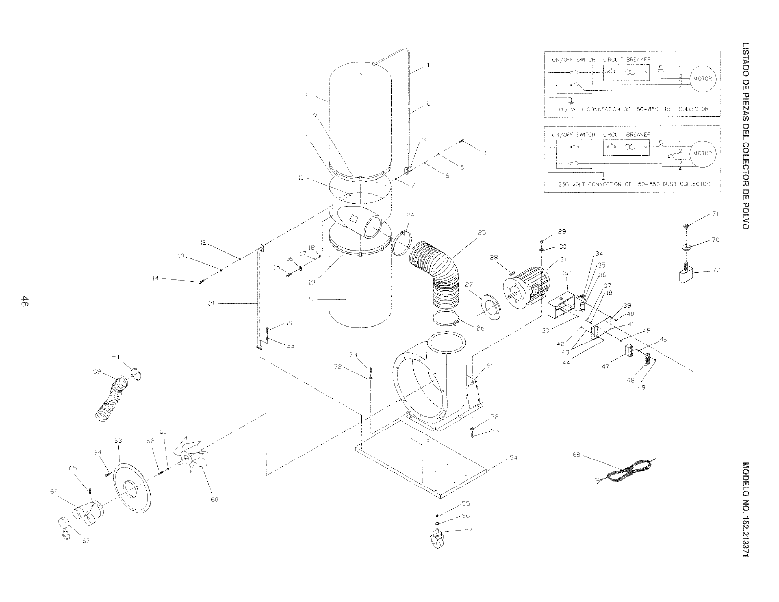
Ob
59
\\
67
p
3_s
18
!7
19
2O
73
\
\
/
/
/
]
[ j/55
i /
_ ,j 56
O4/OFF SWITCH CIRCU{] BREAKER
5 ',/C_T C:CNNE}IlON QF £085!) DiS7 COLLECTOR
{ ON/OFF SWITCfl CRCU]T BREA14ER
4
i $
230 VOL] CONNECTION OF 50-850 BUS] COLLECTOR
37
/38
48 /
49
68
E
O
m
m
N
m
O
o
r
m
o
o
m
o
o
o
m
o
z
P
P

,_ NOTAS ,_
47

iiiiiiiiiiiiiiiiii iiiiiiiiiiiiiiiiiiii
HHHHHHHHHH
iiiiiiiiiiiiiiiiii iiiiiiiiiiiiiiiiiiii
For repair -in your home - of all major brand appliances,
lawn and garden equipment, or heating and cooling systems,
no matter who made it, no matter who sold it!
For the replacement parts, accessories and
ownersmanualsthatyouneedtodoqt°yourselfi
For Sears professional installation of home appliances
and items lime garage door openers and water heaters.
1o800-4- MY- H0 ME®(1-8oo-4ee-4ees)
ome
iiiiiiiiiiiiiiiii
For repair of carry-in products like vacuums, lawn equipment,
iiiiiiiiiiiiiiiii
and electronics, call or go on-line for the location of the nearest
iiiiiiiiiiiiiiiii
Sears Parts & Repair Center.
iiiiiiiiiiiiiiiii
1"-800"-488"-1222
iiiiiiiiiiiiiiiii
Anytime, day or night (U.S.A. only)
www.sears.oorf}
To purchase a protection agreement on a product serviced by Sears:
1-,800,,827,,6655 (u.s.A.> 1,,800,,361 ,,6665 (Canada)
Parapedirserviciode reparacidn a Au Canadapourserviceenfran_ais:
domicilio, yparaordenarpiezas: 1-800-LE-FOYER Me
1-888-SU-HOGAR sM (1-800-533-6937)
(1-888-784-8427) www.sears.ca
TM
® Registered Trademark / Trademark / -_MServiceMark of Sears, Roebuck and Co.
TM
® Mama Registrada / Mama de Fgbrica / - Marca de Servicio de Sears, Roebuck and Co.
ML}
MC Marque de commerce / Marque d6pos6e de Sears, Roebuck and Co. Q Sears, Roebuck and Co.