's I
3/4 Horsepower (continuous duty)
1-1/2 Horsepower (maximum developed)
600 C°FoM°
3450 R.PoM. (no _oad R.PoM.}
Model No.
152.213351
C
CAUTION:
FOR YOUR OWN SAFETY; Read
and follow all of the Safety and
Operating Instructions before
Operating this Dust CoUlector.
Customer Helpline
1-800-897-7709
PRease have your Model No.
and Sedal No. availabUe.
Sears, Roebuck and Co., Hoffman Estates, JL (}0179 U.S.A.
Part No. 0R92122
Revision A
Espa5olpg. 23
SECTmON PAGE
Warranty ..................................................................................... 2
Product Specifications ......................................................................... 2
Safety mnstructions ............................................................................ 3
Grounding mnstructions ......................................................................... 5
Specific Safety mnstructions for Dust Collectors .................................................... 6
Accessories and Attachments ................................................................... 7
Carton Contents .............................................................................. 8
Know Your Dust Collector ...................................................................... 9
Assembly mnstructions ........................................................................ 10
Operating the Dust Collector ................................................................... 14
Dust Collector in the Shop ..................................................................... 15
Maintenance ................................................................................. 18
TroubJeshooting Guide ........................................................................ 18
Parts List ................................................................................... 19
EspaSol ..................................................................................... 23
Service Information ................................................................... Back Cover
FULL ONE YEAR WARRANTY
If this product fails due to a defect in material or workmanship within one year from the date of purchase, return
it to the nearest Sears Service Center for repair, free of charge,
This warranty gives you specific legal rights, and you may also have other rights, which vary, from state to state,
Sears, Roebuck and Co,, Dept 817 WA, Hoffman Estates, IL 60179
induction Motor
Continuous duty HP
Maximum developed HP
Amps
Volts
Hertz
RPM
Collection Bag
Collection Hose
Maximum C, F, M,
Maximum static pressure
in inches of water
Collection Bag capacity
3/4
1-1/2
9,0
120
60
3450 R,P,M,
(no load R,P,M,)
30 micron
4°inch Flexible Hose
6OO
11
3 cubic feet
To avoid electrical shock to yourself and damage to the
Dust Collector, use proper circuit protection, Do not
expose to rain, or use in a damp environment,
The Dust Collector is factory wired for 120V, 60 Hz,
operation, Connect to a 120V, 15 amp branch circuit
and use a 15 amp time delay fuse or circuit breaker,
The electrical circuit cannot have any wire size less
than #14, To avoid shock or fire, replace power cord
immediately if it is damaged in any way,
GENERAL SAFETY iNSTRUCTiONS
Operating a Dust Collector can be dangerous if safety
and common sense are ignored, The operator must be
familiar with the operation of the tool, Read this manual
to understand this Dust Collector, DO NOT operate this
Dust Collector if you do not fully understand the limita-
tions of this tool, DO NOT modify this Dust Collector in
any way, REMEMBER: Your personal safety is your
responsibility,
BEFORE USUNG THE DUST COLLECTOR
9,
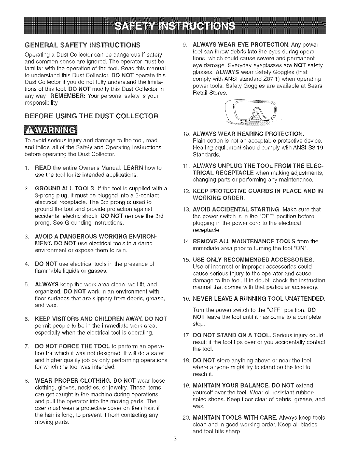
ALWAYS WEAR EYE PROTECTION, Any power
tool can throw debris into the eyes during opera-
tions, which could cause severe and permanent
eye damage, Everyday eyeglasses are NOT safety
glasses, ALWAYS wear Safety Goggles (that
comply with ANSi standard Z87,1) when operating
power tools. Safety Goggles are available at Sears
Retail Stores,
To avoid serious injury and damage to the tool, read
and follow all of the Safety and Operating instructions
before operating the Dust Collector,
1, READ the entire Owner's Manual, LEARN how to
use the tool for its intended applications,
2,
GROUND ALL TOOLS, if the tool is supplied with a
3-prong plug, it must be plugged into a 3-contact
electrical receptacle, The 3rd prong is used to
ground the tool and provide protection against
accidental electric shock, DO NOT remove the 3rd
prong, See Grounding instructions,
3, AVOID A DANGEROUS WORKING ENVIRON-
MENT. DO NOT use electrical tools in a damp
environment or expose them to rain.
4, DO NOT use electrical tools in the presence of
flammable liquids or gasses,
5,
ALWAYS keep the work area clean, well lit, and
organized, DO NOT work in an environment with
floor surfaces that are slippery from debris, grease,
and wax,
6, KEEP VISITORS AND CHILDREN AWAY. DO NOT
permit people to be in the immediate work area,
especially when the electrical tool is operating,
7,
DO NOT FORCE THE TOOL to perform an opera-
tion for which it was not designed, it wiii do a safer
and higher quality job by only performing operations
for which the tool was intended,
8, WEAR PROPER CLOTHING. DO NOT wear loose
clothing, gloves, neckties, or jewelry, These items
can get caught in the machine during operations
and pull the operator into the moving parts, The
user must wear a protective cover on their hair, if
the hair is long, to prevent it from contacting any
moving parts,
10, ALWAYS WEAR HEARING PROTECTION.
Plain cotton is not an acceptable protective device,
Hearing equipment should comply with ANSi $3,19
Standards,
11, ALWAYS UNPLUG THE TOOL FROM THE ELEC-
TRICAL RECEPTACLE when making adjustments,
changing parts or performing any maintenance,
12, KEEP PROTECTIVE GUARDS IN PLACE AND IN
WORKING ORDER.
13,
14,
15,
AVOID ACCIDENTAL STARTING, Make sure that
the power switch is in the "OFF" position before
plugging in the power cord to the electrical
receptacle,
REMOVE ALL MAINTENANCE TOOLS from the
immediate area prior to turning the tool "ON",
USE ONLY RECOMMENDED ACCESSORIES,
Use of incorrect or improper accessories could
cause serious injury to the operator and cause
damage to the tool, if in doubt, check the instruction
manual that comes with that particular accessory,
16, NEVER LEAVE A RUNNING TOOL UNATTENDED,
17,
18,
19,
20,
Turn the power switch to the "OFF" position, DO
NOT leave the tool until it has come to a complete
stop,
DO NOT STAND ON A TOOL, Serious injury could
result if the tool tips over or you accidentally contact
the tool,
DO NOT store anything above or near the tool
where anyone might try to stand on the tool to
reach it.
MAINTAIN YOUR BALANCE. DO NOT extend
yourself over the tool, Wear oil resistant rubber-
soled shoes, Keep floor clear of debris, grease, and
wax,
MAINTAIN TOOLS WITH CARE. Always keep tools
clean and in good working order, Keep all blades
and tool bits sharp,
21,EACHANDEVERYTmME,CHECK FOR DAM-
AGED PARTS PRmOR TO USmNGTHE TOOL,
Carefully check all guards to see that they operate
properly, are not damaged, and perform their
intended functions, Check for alignment, binding or
breaMng of moving parts, A guard or other part that
is damaged should be immediately repaired or
replaced,
22, CHILDPROOF THE WORKSHOP AREA by remov-
ing switch keys, unplugging tools from the electrical
receptacles, and using padlocks,
23, DO NOT OPERATE TOOL IF UNDER THE INFLU-
ENCE OF DRUGS OR ALCOHOL,
24, SECURE ALL WORK, When it is possible, use
clamps or jigs to secure the work-piece, This is
safer than attempting to hold the work-piece with
your hands,
25, STAY ALERT, WATCH WHAT YOU ARE DOING,
AND USE COMMON SENSE WHEN OPERATING
A POWER TOOL. DO NOT USE A TOOL WHILE
TIRED OR UNDER THE INFLUENCE OF DRUGS,
ALCOHOL, OR MEDICATION, A moment of
inattention while operating power tools may result
in serious personal injury.
26, ALWAYS WEAR A DUST MASK TO PREVENT
INHALING DANGEROUS DUST OR AIRBORNE
PARTICLES, including wood dust, crystalline silica
dust and asbestos dust. Direct particles away from
face and body. Always operate tool in well ventilat-
ed area and provide for proper dust removal. Use
dust collection system wherever possible. Exposure
to the dust may cause serious and permanent
respiratory or other injury, including silicosis (a
serious lung disease), cancer, and death. Avoid
breathing the dust, and avoid prolonged contact
with dust. Allowing dust to get into your mouth or
eyes, or lay on your skin may promote absorption
of harmful material. Always use properly fitting
NIOSH/OSHA approved respiratory protection
appropriate for the dust exposure, and wash
exposed areas with soap and water.
27, USE A PROPER EXTENSION CORD IN GOOD
CONDITION, When using an extension cord, be
sure to use one heavy enough to carry the current
your product will draw, Please see minimum recom-
mended gauge for extension cords (AWG) table for
correct sizing of an extension cord, if in doubt, use
the next heavier gauge,
The smaller the gauge number, the larger diameter of
the extension cord. if in doubt of the proper size of an
extension cord, use a shorter and thicker cord. An
undersized cord will cause a drop in line voltage
resulting in a loss of power and overheating. USE
ONLY A 3-WIRE EXTENSION CORD THAT HAS A
3-PRONG GROUNDING PLUG AND A 3-POLE
RECEPTACLE THAT ACCEPTS THE TOOL'S PLUG.
GUJDEUNES FOR
EXTENSION CORDS
If you are using an extension cord outdoors, be sure
it is marked with the suffix "W-A" ("W" in Canada) to
indicate that it is acceptable for outdoor use,
Be sure your extension cord is properly sized, and
in good electrical condition, Always replace a damaged
extension cord or have it repaired by a qualified person
before using it,
Protect your extension cords from sharp objects,
excessive heat, and damp or wet areas,
0 to 6 Amps
6 to t 0 Amps
10 to 12 Amps
120 VOLT OPERATION ONLY
25' LONG
18 AWG
18 AWG
16 AWG
50' LONG
16 AWG
16 AWG
16 AWG
100' LONG
t 6 AWG
t 4 AWG
t 4 AWG
THINSTOOL MUST BE GROUNDED WHmLE mNUSE
TO PROTECT THE OPERATOR FROM ELECTRmC
SHOCK.
mNTHE EVENT OF A MALFUNCTmON OR BREAK-
DOWN, grounding provides the path of bast resistance
for eUectric current and reduces the risk of eUectric
shock, This tooUis equipped with an eUectric cord that
has an equipment-grounding conductor and a ground-
ing pUug,The pUugMUST be pUugged into a matching
eUectrbaUreceptacle that is properUy installed and
grounded in accordance with ALL bcaU codes and
ordinances,
DO NOT MODIFY THE PLUG PROVIDED, if it wHUnot
fit the eUectrbaUreceptacb, have the proper eUectrbaU
receptacle installed by a qualified electrician,
IMPROPER ELECTRICAL CONNECTION of the equip-
ment-grounding conductor can result in risk of electric
shock, The conductor with the green insulation (with or
without yellow stripes) is the equipment-grounding con-
ductor, DO NOT connect the equipment-grounding con-
ductor to a live terminal if repair or replacement of the
electric cord or plug is necessary,
CHECK with a qualified electrician or sewice personnel
if you do not completely understand the grounding
instructions, or if you are not sure the tool is properly
grounded,
The motor supplied with your Dust Collector is a
120-volt, single-phase motor, it is shipped wired for
120-volt application, Never connect the green wire to
a live terminal,
USE ONLY A 3-WIRE EXTENSION CORD THAT HAS
A 3=PRONG GROUNDING PLUG AND A 3-POLE
RECEPTACLE THAT ACCEPTS THE TOOL'S PLUG.
REPLACE A DAMAGED OR WORN CORD IMMEDI-
ATELY.
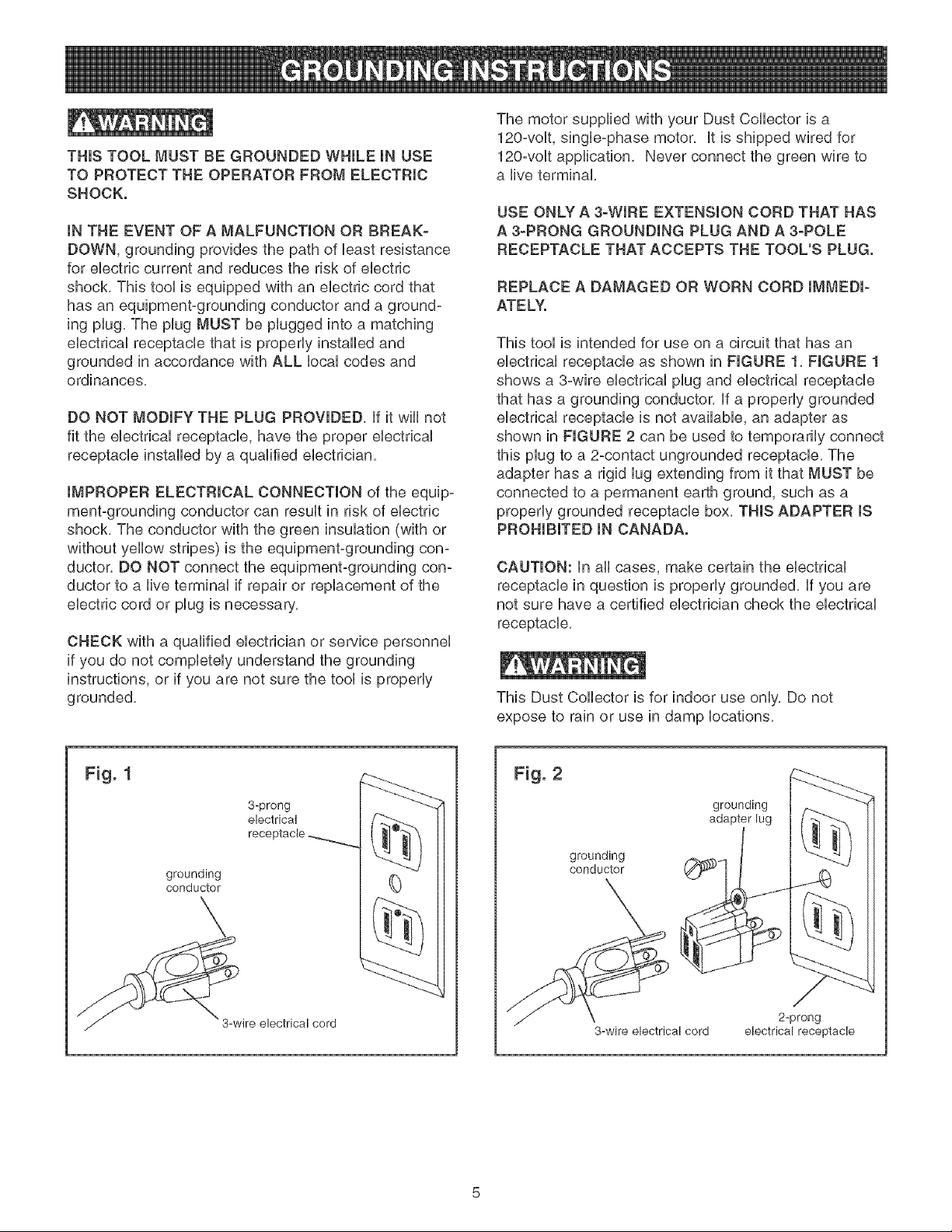
This tool is intended for use on a circuit that has an
electrical receptacle as shown in FIGURE 1, FIGURE 1
shows a 3°wire electrical plug and electrical receptacle
that has a grounding conductor, if a properly grounded
electrical receptacle is not available, an adapter as
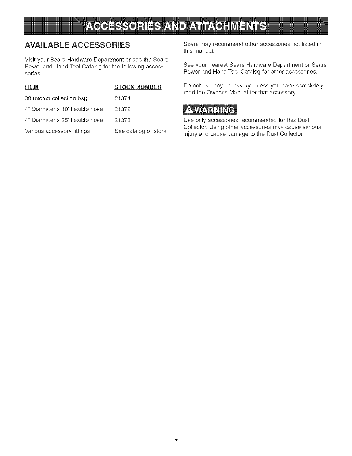
shown in FIGURE 2 can be used to temporarily connect
this plug to a 2-contact ungrounded receptacle, The
adapter has a rigid lug extending from it that MUST be
connected to a permanent earth ground, such as a
properly grounded receptacle box, THIS ADAPTER IS
PROHIBITED IN CANADA.
CAUTION: in all cases, make certain the electrical
receptacle in question is properly grounded, if you are
not sure have a certified electrician check the electrical
receptacle,
This Dust Collector is for indoor use only, Do not
expose to rain or use in damp locations,
Fig. 1
3-prong
electrical
receptacle
grounding
conductor
\
ire electrical cord
(}
Fig. 2
grounding
conductor
grounding
adapter lug
J45
3-wire electrical cord
2-prong
electrical receptacle

SPECiFiC SAFETY iNSTRUCTiONS
FOR DUST COLLECTORS
The operation of any Dust Colbctor can result in debris
being thrown into your eyes, which can result in severe
eye damage, ALWAYS Wear Safety Goggbs (that com-
ply with ANSi standard Z87,1) when operating the Dust
Collector, Safety Goggbs are availabb at Sears Retail
Stores, Keep your thumbs and fingers away from intake
ports,
Basic precautions should always be followed when using
your dust collector, To reduce the risk of injury, electrical
shock or fire, comply with the safety rubs listed below:
1, READ and understand the instruction manual
before operating the dust collector,
2, DO NOT OPERATE THIS MACHINE until it is
assembled and installed according to the instruc-
tions,
3, OBTAIN ADVICE FROM YOUR SUPERVISOR,
instructor, or another qualified person if you are not
familiar with the operation of this machine,
4,
DO NOT leave the dust collector plugged into the
electrical outlet, Unplug dust collector from the out-
let when not in use and before servicing, changing
bags, unclogging and cleaning,
5, ALWAYS turn the power switch "OFF" before
unplugging the dust collector,
6, TO REDUCE THE RISK OF ELECTRICAL
SHOCK, do not use outdoors, Do not expose to
rain, Store indoors, Use only for dry pick up,
7,
FOLLOW all electrical and safety codes, including
the National Electric Code (NEC) and the Occu-
pational Safety and Health Regulations (OSHA), All
electrical connections and wiring should be made
by qualified personnel only,
8, DO NOT handle the plug or dust collector with wet
hands,
9,
DO NOT use the dust collector to pick up flam-
mable or combustible liquids, such as gasoline,
NEVER use the dust collector near any flammable
or combustible liquids,
10, USE the dust collector to pick up wood materials
only, DO NOT use the dust collector to pick up
metal shavings, metal dust, or parts,
11, NEVER use the dust collector to dissipate fumes or
smoke, NEVER pick up anything that is burning or
smoking, such as cigarettes, matches or hot ashes,
12,
13,
14,
15,
16,
17,
18,
19,
20,
21,
22,
23,
24,
25,
USE only as described in this manual, USE acces-
sories only recommended by Sears,
DO NOT pull the dust collector by the power cord,
NEVER allow the power cord to come in contact
with sharp edges, hot surfaces, oil or grease,
DO NOT unplug the dust collector by pulling on the
power cord, ALWAYS grasp the plug, not the cord,
DO NOT handle the plug or dust collector with wet
hands,
REPLACE a damaged cord immediately, DO NOT
use a damaged cord or plug, if the dust collector is
not operating properly, or has been damaged, left
outdoors or has been in contact with water, return it
to a Sears Service Center,
DO NOT use the dust collector as a toy, DO NOT
use near or around children,
DO NOT insert fingers or foreign objects into the
dust intake port, Keep hair, loose clothing, fingers,
and all body parts away from openings and moving
parts of the dust collector,
DO NOT use the dust collector without the dust
collection bag in place and properly secured,
ALWAYS use safety gates or caps to cover dust
ports when the dust collector is not in use or
mounted to a supporting surface for storage,
PERIODICALLY INSPECT dust bag for any cuts,
rips or tears, NEVER operate the dust collector with
a damaged bag or vacuum hose,
The dust collector is designed for home use or light
commercial duty ONLY,
CONNECT dust collector to a properly grounded
outlet only, See grounding instructions,
ADDITIONAL INFORMATION regarding the safe
and proper operation of this product is available
from the National Safety Council, 1121 Spring Lake
Drive, Itasca, IL 60143-3201 in the Accident Pre-
vention Manual for Industrial Operation and also in
the Safety Data Sheets provided by the NSC,
Please also refer to the American National Stand-
ards institute ANSi 01,1 Safety Requirements for
Woodworking Machinery and the U,S, Department
of Labor OSHA 1910,213 Regulations,
SAVE THESE INSTRUCTIONS, Refer to them
frequently and use them to instruct other users,
AVAILABLE ACCESSORIES
Visit your Sears Hardware Department or see the Sears
Power and Hand Tool Catalog for the following acces-
series,
ITEM
30 micron collection bag
4" Diameter x 10' flexible hose
4" Diameter x 25' flexible hose
Various accessory fittings
STOCK NUMBER
21374
21372
21373
See catalog or store
Sears may recommend other accessories not listed in
this manual,
See your nearest Sears Hardware Department or Sears
Power and Hand Tool Catalog for other accessories,
Do not use any accessory unless you have completely
read the Owner's Manual for that accessory,
Use only accessories recommended for this Dust
Collector, Using other accessories may cause serious
injury and cause damage to the Dust Collector,
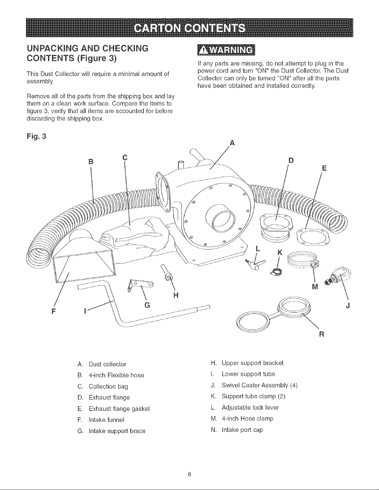
UNPACKING AND CHECKING
CONTENTS (Figure 3)
This Dust Collector will require a minimal amount of
assembly,
Remove all of the parts from the shipping box and lay
them on a clean work surface, Compare the items to
figure 3, verify that all items are accounted for before
discarding the shipping box,
if any parts are missing, do not attempt to plug in the
power cord and turn "ON" the Dust Collector, The Dust
Collector can only be turned "ON" after all the parts
have been obtained and installed correctly,
Fig. 3
B
C
A
D
d
A, Dust collector
B, 4-inch Flexible hose
C, Collection bag
D, Exhaust flange
E, Exhaust flange gasket
R intake funnel
G, intake support brace
H, Upper support bracket
I, Lower support tube
J, Swivel Caster Assembly (4)
K, Support tube clamp (2)
L, Adjustable lock lever
M, 4°inch Hose clamp
N, intake port cap
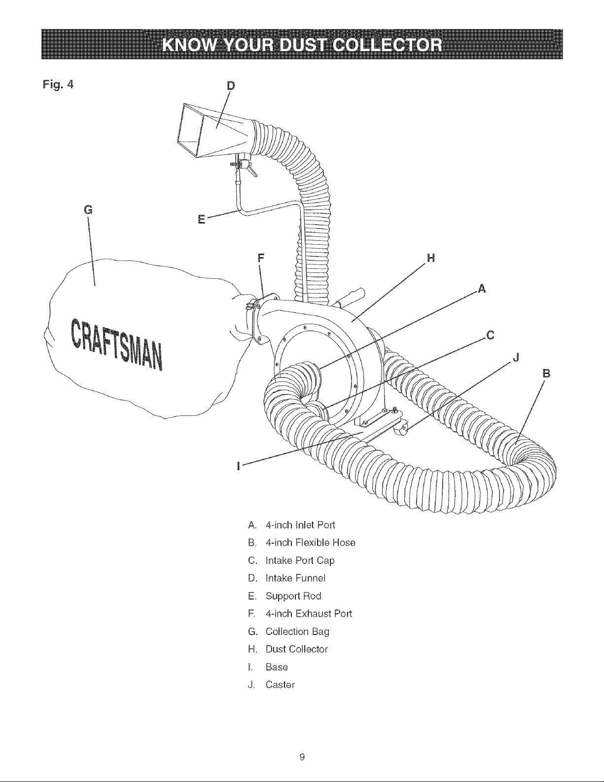
Fig. 4 D
G
E
F
B
A, 4-inch HnHetPort
B, 4-inch FHexibHeHose
C, Hntake Port Cap
D, Hntake FunneH
E, Support Rod
R 4-inch Exhaust Port
G, CoHHectionBag
H, Dust CoHHector
H, Base
J, Caster
2,
2,
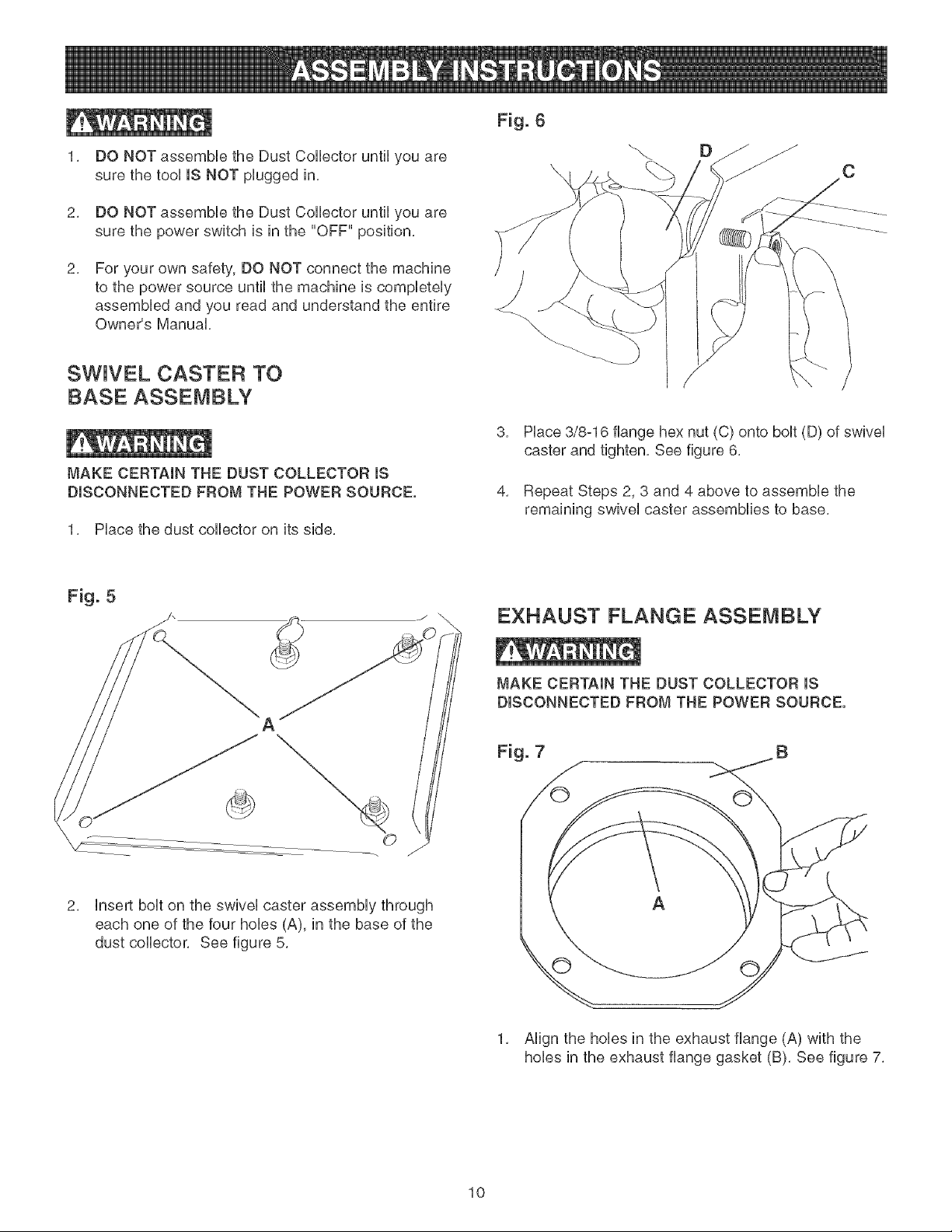
DO NOT assemble the Dust Collector until you are
sure the tool iS NOT plugged in,
DO NOT assemble the Dust Collector until you are
sure the power switch is in the "OFF" position,
For your own safety, DO NOT connect the machine
to the power source until the machine is completely
assembled and you read and understand the entire
Owner's Manual,
SWIVEL CASTER TO
BASE ASSEMBLY
MAKE CERTAIN THE DUST COLLECTOR IS
DISCONNECTED FROM THE POWER SOURCE.
1, Place the dust collector on its side,
Fig. 6
3,
4,
Place 3/8=16 flange hex nut (C) onto bolt (D) of swivel
caster and tighten, See figure 6,
Repeat Steps 2, 3 and 4 above to assemble the
remaining swivel caster assemblies to base,
Fig. 5
)
A
EXHAUST FLANGE ASSEMBLY
MAKE CERTAIN THE DUST COLLECTOR iS
DISCONNECTED FROM THE POWER SOURCE.
2, insert bolt on the swivel caster assembly through
each one of the four hobs (A), in the base of the
dust collector, See figure 5,
1, Align the hobs in the exhaust flange (A) with the
hobs in the exhaust flange gasket (B), See figure 7,
10
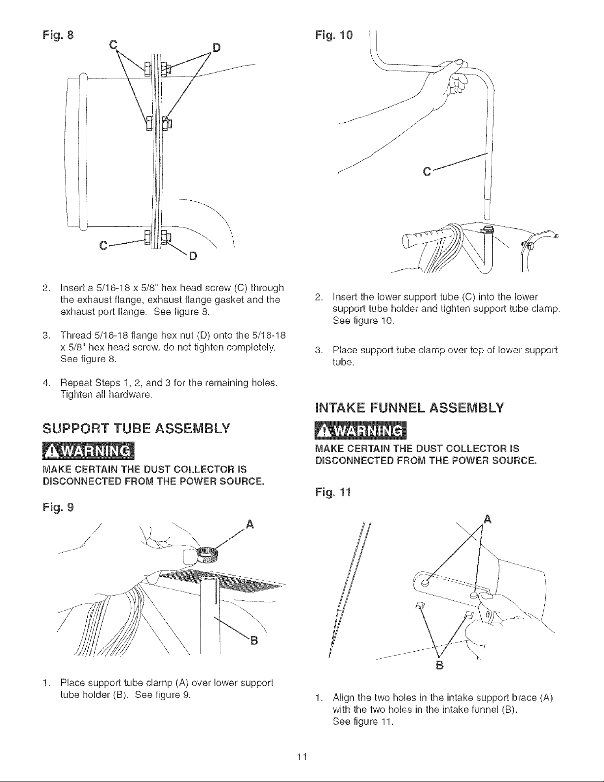
Fig. 8 Fig. 10
C D
C
\
\
2,
8,
4,
insert a 5/16-18 x 5/8" hex head screw (C) through
the exhaust flange, exhaust flange gasket and the
exhaust port flange, See figure 8,
Thread 5/16-18 flange hex nut (D) onto the 5/16=18
x 5/8" hex head screw, do not tighten completely,
See figure 8,
Repeat Steps 1,2, and 3 for the remaining hobs,
Tighten all hardware,
SUPPORT TUBE ASSEMBLY
MAKE CERTAIN THE DUST COLLECTOR IS
DISCONNECTED FROM THE POWER SOURCE.
A
1, Place support tube clamp (A) over lower support
tube holder (B), See figure 9,
2, insert the lower support tube (C) into the lower
support tube holder and tighten support tube clamp,
See figure 10,
3, Place support tube clamp over top of lower support
tube,
iNTAKE FUNNEL ASSEMBLY
MAKE CERTAIN THE DUST COLLECTOR IS
DISCONNECTED FROM THE POWER SOURCE.
B
A
\
1, Align the two hobs in the intake support brace (A)
with the two hobs in the intake funnel (B),
See figure 11,
11
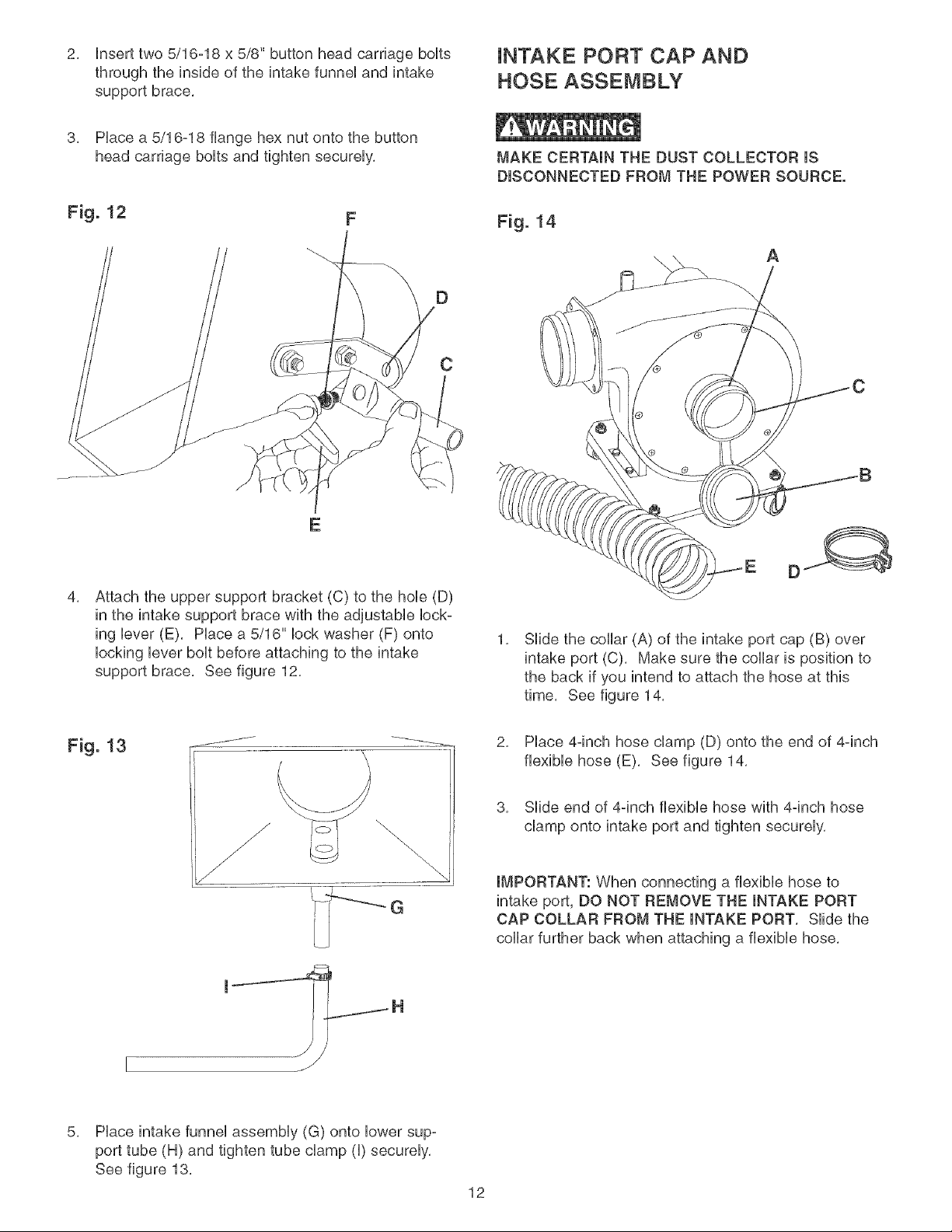
2. Hnserttwo5/16-18x 5/8"buttonheadcarriageboHts
throughtheinsideoftheintakefunneiandintake
supportbrace.
iNTAKE PORT CAP AND
HOSE ASSEMBLY
3. Piace a 5/16-18 flange hex nut onto the button
head carriage boits and tighten secureiy.
F
E
D
MAKE CERTAIN THE DUST COLLECTOR IS
DISCONNECTED FROM THE POWER SOURCE.
Fig. 14
A
C
4,
Attach the upper support bracket (C) to the hob (D)
in the intake support brace with the adjustabie Hock-
ing iever (E). Piace a 5/16" Hockwasher (F) onto
Hocking iever boit before attaching to the intake
support brace. See figure 12.
1,
E D
SHde the collar (A) of the intake port cap (B) over
intake port (C). Make sure the collar is position to
the back if you intend to attach the hose at this
time. See figure 14.
Fig 13 .J_--..........
G
2. PHace4-inch hose champ (D) onto the end of 4qnch
fiexibie hose (E). See figure 14.
3. Siide end of 4-inch fiexibie hose with 4-inch hose
champ onto intake port and tighten secureiy.
IMPORTANT: When connecting a flexibie hose to
intake port, DO NOT REMOVE THE INTAKE PORT
CAP COLLAR FROM THE INTAKE PORT. Siide the
collar further back when attaching a fiexibie hose.
5,
Place intake funnel assembly (G) onto lower sup-
port tube (H) and tighten tube clamp (I) securely,
See figure 13,
12
G
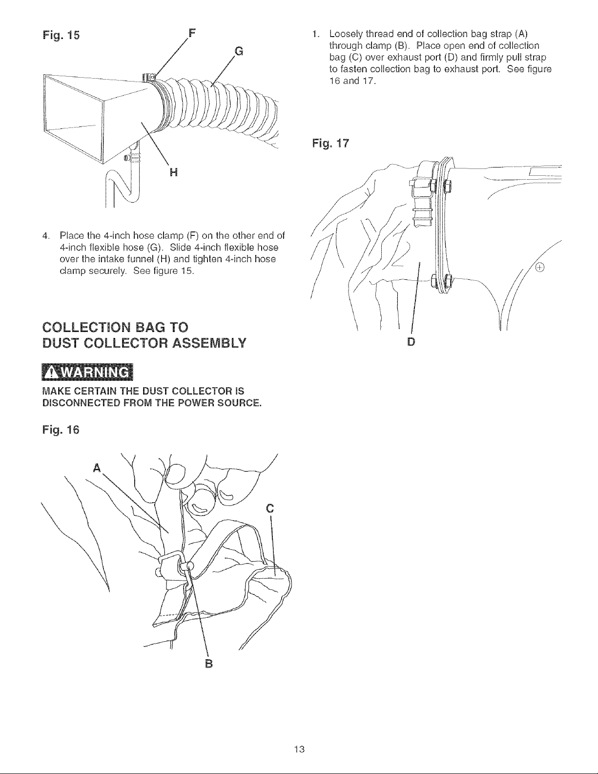
Loosely thread end of collection bag strap (A)
through clamp (B), Place open end of collection
bag (C) over exhaust port (D) and firmly pull strap
to fasten collection bag to exhaust port, See figure
16 and 17,
H
4,
Place the 4-inch hose clamp (F) on the other end of
4-inch flexible hose (G), Slide 4-inch flexible hose
over the intake funnel (H) and tighten 4-inch hose
clamp securely, See figure 15,
COLLECTION BAG TO
DUST COLLECTOR ASSEMBLY
D
j ................
jf
/
/
/
MAKE CERTAIN THE DUST COLLECTOR iS
DISCONNECTED FROM THE POWER SOURCE.
Fig. 16
A
C
B
13
FOROPERATORSAFETY,keepfingersandaliforeign
objectsoutoftheintakeports,Therotatingfaninside
theMowerhousingisaccessibiethroughtheintake
portsandishazardous,Donotwearboseciothingor
jeweiry,Makecertainthateachintakeportwhichisnot
beingusedor attachedto a dustcollectionsystemis
coveredwithan intakeportcap,
CONNECTING TOOL TO
POWER SOURCE
A separate eHectrbaHcircuit shouid be used for your
toois, This circuit shouid not be Hessthan #14 A. W, G,
wire and shouid be protected with a 15-amp time Hag
fuse, Have a qualified electrbian repair or repiace dam-
aged or worn cord immediateiy, Before connecting the
motor to the power iine, make certain the switch is in
the "OFF" position and be sure that the electric current
is of the same characteristics as stamped on the motor
namepiate, AHHiine connections shouid make good con-
tact, Running on Howvoitage wili damage the motor,
LOCKING SWITCH JN THE
"OFF" POSiTiON
When the Dust Collector is not in use, the switch key
(B) shouid be removed so that it cannot be started,
Grasp the switch key and puli it out of the switch
assembiy, With the switch key removed, the switch
wili not operate, However, shouid the switch key be
removed while the dust collector is running, it can be
turned "OFF", but cannot be restarted without inserting
the switch key, See figure 18,
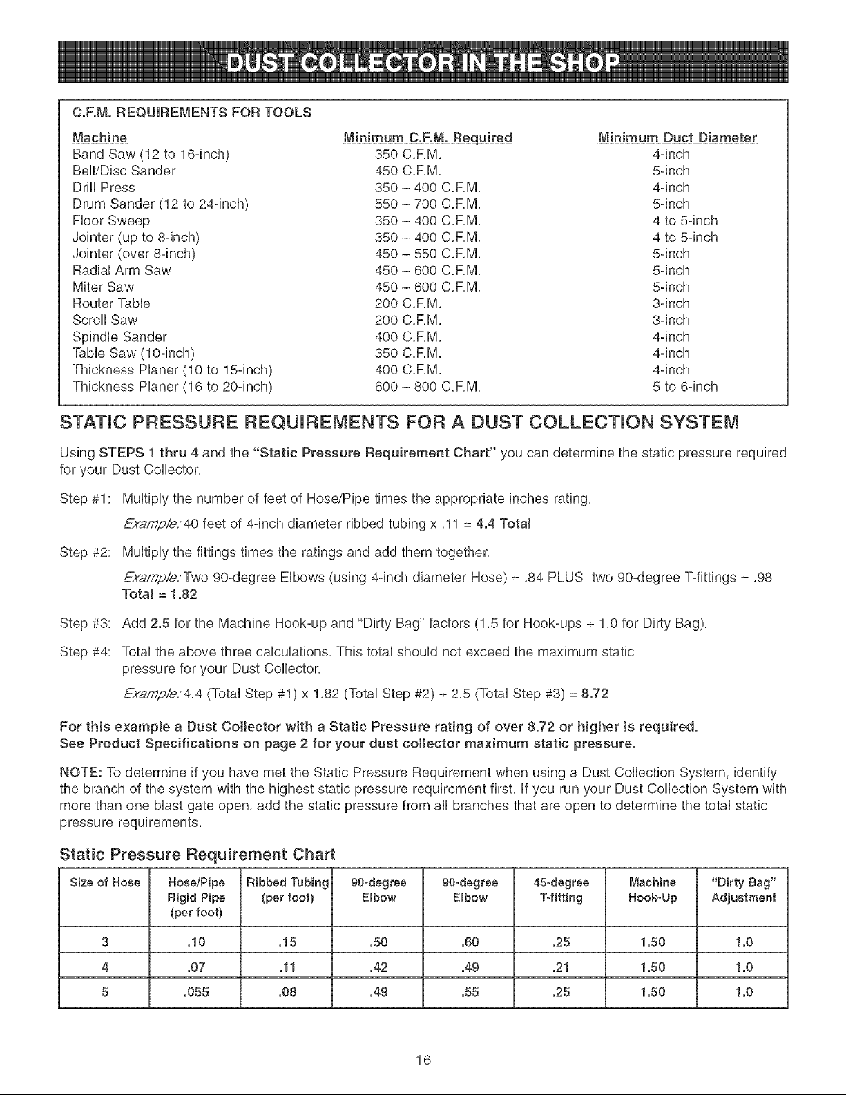
TRANSPORTATION AND STORAGE
MAKE CERTAmN THE DUST COLLECTOR ms
DmSCONNECTED FROM THE POWER SOURCE.
Fig. 19
DO NOT EXPOSE THE DUST COLLECTOR TO RAIN
OR OPERATE THE MACHINE IN DAMP LOCATIONS.
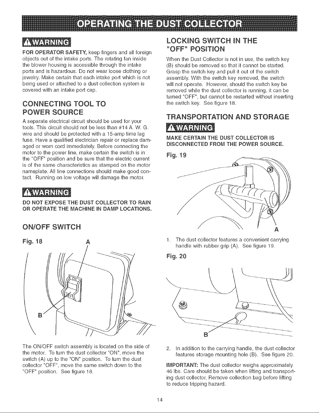
ON/OFF SWITCH
Fig. 18
/
A
\
The ON/OFF switch assembiy is iocated on the side of
the motor, To turn the dust collector "ON", move the
switch (A) up to the "ON" position, To turn the dust
collector "OFF", move the same switch down to the
"OFF" position, See figure 18,
__'_" A
1. The dust collector features a convenient carG,ing
handle with rubber grip (A). Bee figure 19.
Fig. 20
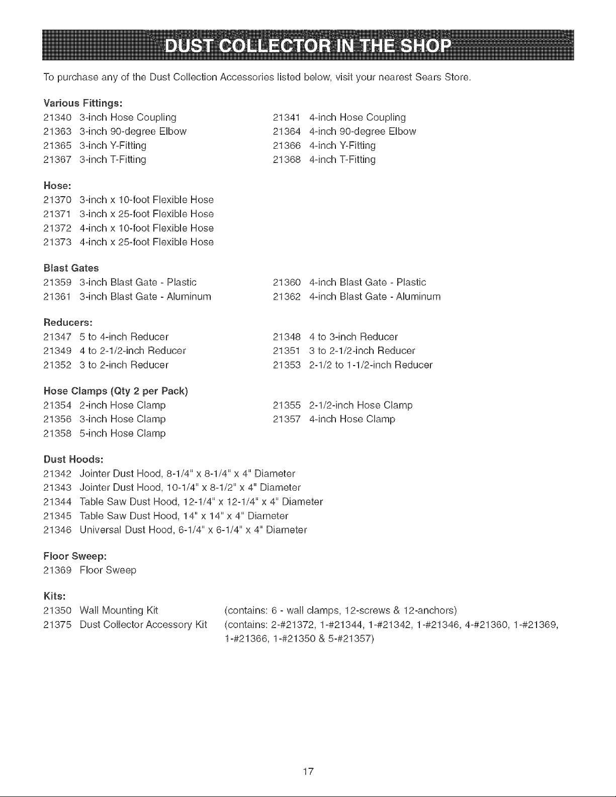
2. in addition to the carrying handle, the dust collector
features storage mounting hob (B). Bee figure 20.
IMPORTANT: The dust collector weighs approximately
46 Ibs. Care should be taken when lifting and transport-
ing dust collector. Remove collection bag before lifting
to reduce tripping hazard.
14

Belowaresometermsthatwiiihelpyouto understand
andsetupyourDustCollectoranddesignyourown
DustCollectionSystem,
DustCollector- A machineusedto collectfinewood
dustandchips,
DustCollectionSystem- Adustcollectorconnected
to multiplewoodworkingmachinesutilizingvarious
typesof hose/pipeandfittings,
C.F.M.= CubicFeet/Minute- A measurementof the
amountof airvolumethatcanmovethrougha dust
collectorin oneminute,
StaticPressure- A measurementof theamountof the
resistanceto airflowin adustcollectionsystem,
THINGSTOCONSIDER:
WhatisthemaximumC,RM,requiredforeachtool
youintendto use?YourDustCollectorshouldbe
ratedforthetoolthathasthehighestC,RM,
•Wiii twoormoretoolsberunningat thesametime?
TheDustCollectorshouldberatedto handlethe
combinedC,RM,requirementsof alloperatingtools,
15
HELPFULHINTS:
, Alwaysrunthelargestappropriatediameterhose
asfaraspossible,Runningasmallerdiameterhose
wiiigreatlyreducetheC,F,M,at thetool,yielding
marginaldustcollection,
Theuseof a lowratedmicronfilterandcollection
bagcanincreasetheeffectivenessofyourdust
collectorin removingfineparticlesofdust,
Determineif youaretouseyourDustCollectorin a
DustCollectionSystemorasa directhook-uptoan
individualtookif usedin a DustCollectionSystem,
reviewStaticPressureRequirementsbelow,
Toprotectyourselffroma staticshock,groundthedust
collectionsystemto a knownground,
if usingthe DustCollectorina DustCollectorSystem,
makecertainto:
Groundthedustcollectionsystemtoaknownground,
Alwayskeepblastgatesclosedto unusedtools,
Makeall runsas shortaspossible,minimizingthe
numberofbendsor turnsthatcouldgreatlyreduce
theefficiencyof yourDustCollector,
PositionthetoolsthathavethehighestC,RM,
ratingsclosesttotheDustCollector,
C.F.M.REQUIREMENTSFORTOOLS
Machine Minimum C.F._,_.Required Minimum Duct Diameter
Band Saw (12 to 16qnch) 350 C,F,M, 4qnch
BeWDbc Sander 450 C,F,M, 5qnch
DrHUPress 350 - 400 C,RM, 4qnch
Drum Sander (12 to 24qnch) 550 - 700 C,RM, 5qnch
Fbor Sweep 350 - 400 C,RM, 4 to 5qnch
Jointer (up to 8qnch) 350 - 400 C,RM, 4 to 5qnch
Jointer (over 8qnch) 450 - 550 C,RM, 5qnch
RadiaUArm Saw 450 - 600 C,RM, 5qnch
Miter Saw 450 - 600 C,RM, 5qnch
Router TaMe 200 C,F,M, 3qnch
Scroll Saw 200 C,F,M, 3qnch
Spindb Sander 400 C,F,M, 4qnch
TaMe Saw (lOqnch) 350 C,F,M, 4qnch
Thickness Haner (10 to 15qnch) 400 C,F,M, 4qnch
Thickness Planer (16 to 20qnch) 600 - 800 C,RM, 5 to 6qnch
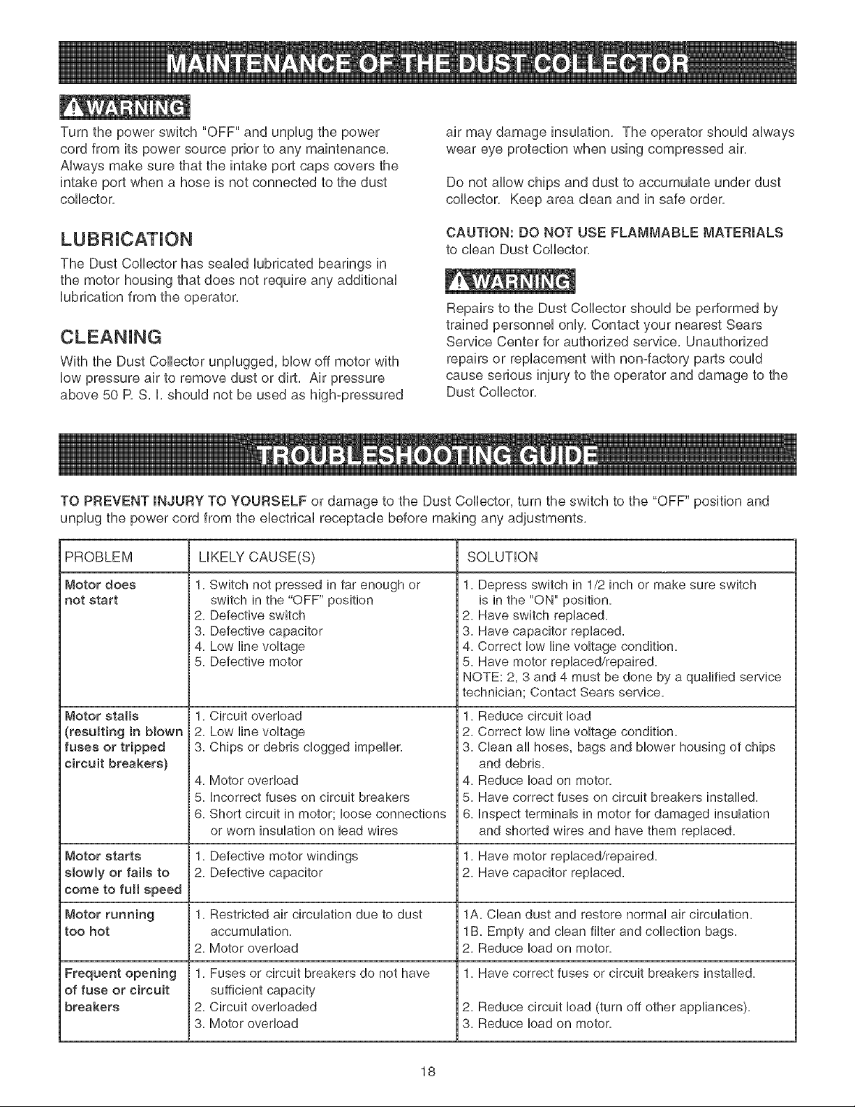
STATIC PRESSURE FIEQUJF{EMENTS FOR A DUST COLLECTION SYSTEM
Using STEPS 1 thru 4 and the "Static Pressure Requirement Chart" you can determine the static pressure required
for your Dust Collector,
Step #1: Multiply the number of feet of Hose/Pipe times the appropriate inches rating,
Exampie; 40 feet of 4-inch diameter ribbed tubing x ,11 = 4.4 Total
Step #2: Multiply the fittings times the ratings and add them together,
Examp/e:Tw, o 90-degree Elbows (using 4qnch diameter Hose) = ,84 PLUS two 90-degree T-fittings = ,98
TotaJ = 1.82
Step #3:
Step #4:
Add 2.5 for the Machine Hook-up and "Dirty Bag" factors (1,5 for Hook-ups + 1,0 for Dirty Bag),
Total the above three calculations, This total should not exceed the maximum static
pressure for your Dust Collector,
Exaf_pie/4,4 (Total Step #1) x 1,82 (Total Step #2) + 2,5 (Total Step #3) = 8.72
For this example a Dust Collector with a Static Pressure rating of over 8.72 or higher is required.
See Product Specifications on page 2 for your dust collector maximum static pressure.
NOTE: To determine if you have met the Static Pressure Requirement when using a Dust Collection System, identify
the branch of the system with the highest static pressure requirement first, If you run your Dust Collection System with
more than one blast gate open, add the static pressure from all branches that are open to determine the total static
pressure requirements,
Static Pressure Requirement Chart
Size of Hose Hose/Pipe Ribbed Tubing 90-degree 90-degree 45-degree Machine "Dirty Bag"
Rigid Pipe (per foot) Elbow Elbow Tofitting Hook-Up Adjustment
(per foot}
3 .10 .15 .50 .60 .25 1.50 1.0
4 .07 .11 .42 .49 .21 1.50 1.0
5 .055 .08 .49 .55 .25 1.50 1.0
16
TopurchaseanyoftheDustCollectionAccessorieslistedbelow,visityournearestSearsStore,
VariousFittings:
21340 3=inchHoseCoupling 21341
21363 3=inch90=degreeElbow 21364
21365 3=inchY=Fitting 21366
21367 3=inchT=Fitting 21368
4-inchHoseCoupling
4-inch90-degreeElbow
4-inchYoFitting
4-inchToFitting
HOSe:
21370
21371
21372
21373
3-inch x lO-foot Flexible Hose
3-inch x 25-foot Flexible Hose
4-inch x lO-foot Flexible Hose
4-inch x 25-foot Flexible Hose
Blast Gates
21359 3-inch Blast Gate - Plastic
21361 3-inch Blast Gate - Aluminum
21360 4-inch Blast Gate - Plastic
21362 4-inch Blast Gate - Aluminum
Reducers:
21347 5 to 4-inch Reducer
21349 4 to 2-1/2-inch Reducer
21352 3 to 2-inch Reducer
21348
21351
21353
4 to 3-inch Reducer
3 to 2-1/2-inch Reducer
2-1/2 to lq/2-inch Reducer
Hose Clamps (Qty 2 per Pack)
21354 2-inch Hose Clamp
21356 3-inch Hose Clamp
21358 5-inch Hose Clamp
21355
21357
2-112-inch Hose Clamp
4-inch Hose Clamp
Dust Hoods:
21342
21343
21344
21345
21346
Jointer Dust Hood, 8-1/4" x 8-1/4" x 4" Diameter
Jointer Dust Hood, 10-1/4" x 8-1/2" x 4" Diameter
Table Saw Dust Hood, 12-1/4" x 12-1/4" x 4" Diameter
Table Saw Dust Hood, 14" x 14" x 4" Diameter
Universal Dust Hood, 6-1/4" x 6-1/4" x 4" Diameter
Floor Sweep:
21369 Floor Sweep
Kits:
21350
21375
Wall Mounting Kit
Dust Collector Accessory Kit
(contains: 6 - wall clamps, 12-screws & 12-anchors)
(contains: 2°#21372, 1°#21344, 1°#21342, 1°#21346, 4-#21360, 1 °#21369,
1°#21366, 1 °#21350 & 5-#21357)
17
Turnthepowerswitch"OFF"andunplugthepower
cordfromitspowersourcepriortoanymaintenance,
Alwaysmakesurethattheintakeportcapscoversthe
intakeportwhena hoseis notconnectedtothedust
collector.
TheDustCollectorhassealedlubricatedbearingsin
themotorhousingthatdoesnotrequireanyadditional
lubricationfromtheoperator,
WiththeDustCollectorunplugged,blowoffmotorwith
lowpressureairto removedustor dirt, Air pressure
above50 R S. I.shouldnotbeusedashigh-pressured
airmaydamageinsulation.Theoperatorshouldalways
weareyeprotectionwhenusingcompressedair.
Donotallowchipsanddusttoaccumulateunderdust
collector.Keepareacleanandinsafeorder.
CAUTION:DONOTUSEFLAMMABLEMATERIALS
tocleanDustCollector.
Repairsto theDustCollectorshouldbeperformedby
trainedpersonnelonly.ContactyournearestSears
ServiceCenterforauthorizedservice.Unauthorized
repairsor replacementwithnon-factorypartscould
causeseriousinjurytotheoperatoranddamageto the
DustCollector.
TOPREVENTINJURYTOYOURSELFor damageto theDustCollector,turntheswitchto the"OFF"positionand
unplugthepowercordfromtheelectricalreceptaclebeforemakinganyadjustments,
PROBLEM
Motor does
not start
Motor stalls
(resulting in blown
fuses or tripped
circuit breakers)
Motor starts
slowly or falls to
come to full speed
Motor running
too hot
Frequent opening
of fuse or circuit
breakers
LIKELY CAUSE(S) SOLUTION
1. Switch not pressed in tar enough or
switch in the "OFF" position
2. Detective switch
3. Detective capacitor
4. Low line voltage
5. Detective motor
1.
2.
3.
4.
5.
6.
1.
2.
1. Depress switch in 1/2 inch or make sure switch
is in the "ON" position.
2. Have switch replaced.
3. Have capacitor replaced.
4. Correct low line voltage condition.
5. Have motor replaced/repaired.
NOTE: 2, 3 and 4 must be done by a qualitied service
technician; Contact Sears service.
Circuit overload 1.
Low line voltage 2.
Chips or debris clogged impeller. 3.
Motor ovedoad 4.
incorrect tuses on circuit breakers 5.
Short circuit in motor; loose connections 6.
or worn insulation on lead wires
Detective motor windings 1.
Detective capacitor
1. Restricted air circulation due to dust
accumulation.
2. Motor overload
1. Fuses or circuit breakers do not have
sufficient capacity
2. Circuit overloaded
3. Motor overload
Reduce circuit load
Correct low line voltage condition.
Clean all hoses, bags and blower housing of chips
and debris.
Reduce load on motor.
Have correct tuses on circuit breakers installed.
inspect terminals in motor for damaged insulation
and shorted wires and have them replaced.
Have motor replaced/repaired.
2. Have capacitor replaced.
1A, Clean dust and restore normal air circulation.
1B. Empty and clean tilter and collection bags.
2. Reduce load on motor.
1. Have correct tuses or circuit breakers installed.
2. Reduce circuit load (turn off other appliances).
3. Reduce load on motor.
18
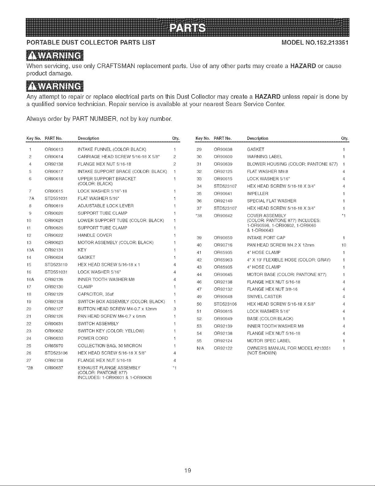
PORTABLEDUSTCOLLECTORPARTSUST MODELNO.152.213351
Whenservicing,useonlyCRAFTSMANreplacementparts,Useof anyotherpartsmaycreatea NAZARDorcause
productdamage,
Anyattemptto repairor replaceelectricalpartsonthisDustCollectormaycreatea NAZARDunlessrepairisdoneby
aqualifiedservicetechnician,Repairserviceisavailableat yournearestSearsServiceCenter,
Alwaysorderby PARTNUMBER,notbykeynumber,
Key No, PART No,
1 OR90613
2 OR90614
4 OR92138
5 OR90617
6 OR90618
7 OR90815
7A STD551031
8 OR90619
9 OR90620
10 OR90621
11 OR90620
12 OR90622
13 OR90623
13A OR92131
14 OR90624
15 STD523110
16 STD551031
16A OR92139
17 OR92130
18 OR92129
19 OR92128
20 OR92127
21 OR92126
22 OR90631
23 OR90632
24 OR90633
25 OR65970
26 STD523106
27 OR92138
*28 OR90637
Description
iNTAKE FUNNEL (COLOR BLACK)
CARRIAGE HEAD SCREW 5/16-18 X 5/8"
FLANGE HEX NUT 5/16-18
iNTAKE SUPPORT BRACE (COLOR: BLACK)
UPPER SUPPORT BRACKET
(COLOR: BLACK)
LOCK WASHER 5/16"-18
FLAT WASHER 5/16"
ADJUSTABLE LOCK LEVER
SUPPORT TUBE CLAMP
LOWER SUPPORTTUBE (COLOR: BLACK)
SUPPORT TUBE CLAMP
HANDLE COVER
MOTOR ASSEMBLY (COLOR: BLACK)
KEY
GASKET
HEX HEAD SCREW 5/16-18 x 1
LOCK WASHER 5/16"
INNER TOOTH WASHER M8
CLAMP
CAPACITOR, 35uf
SWITCH BOX ASSEMBLY (COLOR: BLACK)
BUTTON HEAD SCREW M4-0,7 x 12ram
PAN HEAD SCREW M4-0,7 x 6turn
SWITCH ASSEMBLY
SWITCH KEY (COLOR: YELLOW)
POWER CORD
COLLECTION BAG 30 MICRON
HEX HEAD SCREW 5/16-18 X 5/8"
FLANGE HEX NUT 5/16-18
EXHAUST FLANGE ASSEMBLY
(COLOR: PANTONE 877)
INCLUDES: 1-OR90601 & 1-OR90636
Qty. Key No. PARTNo.
1 29 0R90638
2 30 OR90600
2 31 OR90639
1 32 OR92125
1 33 OR90615
34 STD523107
1
35 OR90641
1
36 OR92140
1
37 STD523107
1
*38 OR90642
1
1
1
39 OR90650
1
40 OR90716
1
41 OR65935
1
42 OR65963
4
43 OR65935
4
44 OR90645
4
46 OR92138
1
47 OR92132
1
49 OR90648
1
50 STD523106
3
51 OR90615
1
52 OR90649
1
53 OR92139
1
54 OR92138
1
55 OR92124
1
N/A 0R92122
4
4
Description Qfry.
GASKET 1
WARNING LABEL 1
BLOWER HOUSING (COLOR: PANTONE 877) 1
FLAT WASHER M9.8 4
LOCK WASHER 5/18' 4
HEX HEAD SCREW 5/18-18 X .'5/4" 4
iMPELLER 1
SPECIAL FLAT WASHER 1
HEX HEAD SCREW 5/18-18 X 3/4" 1
COVER ASSEMBLY "1
(COLOR: PANTONE 877) iNCLUDES:
1-0R90598, 1-OR90602, 1-OR9060
& 1-OR90643
INTAKE PORT CAP 1
PAN HEAD SCREW M4.2 X 12rnrn 10
4" HOSE CLAMP 1
4" X 10' FLEXIBLE HOSE (COLOR: GRAY) 1
4" HOSE CLAMP 1
MOTOR BASE (COLOR: PANTONE 877) 1
FLANGE HEX NUT 5/16-18 4
FLANGE HEX NUT 3/8-16 4
SWIVEL CASTER 4
HEX HEAD SCREW 5/16-18 X 5/8" 4
LOCK WASHER 5/16" 4
BASE (COLOR BLACK) 1
INNER TOOTH WASHER M8 4
FLANGE HEX NUT 5/16-18 4
MOTOR SPEC LABEL 1
OWNER'S MANUAL FOR MODEL #213351 1
(NOT SHOWN)
19
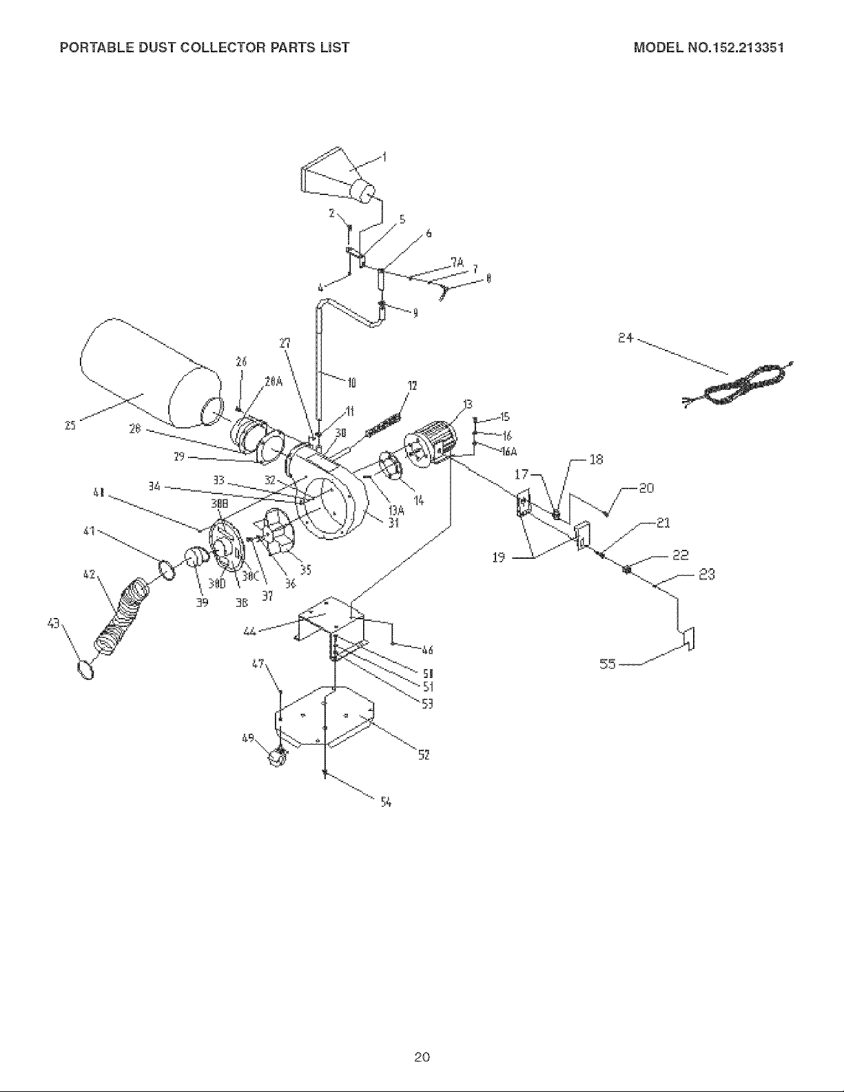
PORTABLEDUSTCOLLECTORPARTSUST MODELNO,152,213351
55--
52
20

,_ NOTES ,_
21

,_ NOTES ,_
22

anual Propietario
3/4 cabaHo de fuerza (servicio continuo)
1-1/2 cabaHos de fuerza (ma×imo desarroHado}
600 C.F.M. (pies c_bicos pot minuto)
3450 R.PoM. (R.PoM. sin carga)
COLE
No. de Mode_o
152.213351
C
PARA SU SEGURIDAD PERSONAL:
Lea y obedezca todas Ras
tnstrucciones de Seguridad y
Funcionamiento antes de accionar
este CoUector de PoUvo.
Sears, Roebuck and Co., Hoffman Estates, JL 60179 U.S.A.
No. de Pieza OR92122
Revisado A
23
Linea de Ayuda al Cliente
1°800°897°7709
Sirvase tenet listo su No. de
Modelo y No. de Serie
SECCION PAGINA
Garant[a .........................................................................................................................................24
Especificaciones de_Producto ...................................................................................................24
Instrucciones de Seguridad ........................................................................................................25
Instrucciones de Cone×i6n a Tierra ...........................................................................................27
Instrucciones de Seguridad Especfficas pare los Colectores de Polvo ................................28
Accesorios y Aditamentos ..........................................................................................................29
Contenido de la Caja....................................................................................................................30
Conozca su Colector de Polvo ...................................................................................................31
Instrucciones de Montaje ............................................................................................................32
Accionando el Co_ector de Polvo ............................................................................................... 36
Colector de Polvo en el Taller ..................................................................................................... 37
Mantenimiento .............................................................................................................................. 40
Gu[a de LocaHzaci6n de Aver[as ................................................................................................ 40
Listado de Piezas ......................................................................................................................... 41
Informaci6n de Servicio .......................................................................................... Contraportada
GARANTHA COMPLETA DE UN Al_O
Si este producto faHadebido a un defecto matedaHo de eHaboraci6ndentro de un a[io desde la fecha de compra, devu61o
valo a su Centre de Servicio Sears mas cercano y la reparaci6n se realizarb, sin costo alguno.
Esta garantia le otorga derechos legales especificos, y tambien puede tenet otros derechos que varian de un estado al
otro.
Sears, Roebuck and Co, DepL 817 WA, Hoffman Estates, IL 60179.
Motor de Inducci6n
HP (CF) de servicio continuo 3/4
HP (CF) mAximo desarroJlado 1-1/2
Amperios 9.0
VoJtios 120
Hertzios 60
RPM 3450 R.RM.
(R.RM. sin carga)
Bolsa de recolecci6n 30 micras
Manguera de recoJecci6n Manguera flexible de
4 putg.
C.RM. (pies cObicos por minuto)
maximo 600
Presi6n estatica maxima
en pulgadas de agua 11
Capacidad de la bolsa de
recolecci6n 3 pies cObicos
Utilice Ia protecci6n correcta de circuitos para evitar los
choques electricos contra su persona y el da[io al Colector de
Polvo. No Ia exponga a la JJuvia n[ tampoco haga uso de eJJa
en entornos hOmedos.
El Colector de Polvo esta cableado de fabrica para un
funcionamiento a 120 V, 60 Hz. Conectela a un cJrcuito de
derivaci6n de 120 V, 15 amperios y utilice un fusible o
disyuntor de circuitos de retardaci6n de 15 amperios. E!
circuito eJectrico no puede tenet un tamaSo de cabIe menor
de #14. Reponga el cord6n de energia inmediatamente si se
daF_aen cuaIquier manera para evitar los choques o
incendios.
24
INSTRUCCUONES GENERALES DE
SEGURIDAD
E! funcionamiento de un Colector de Polvo puede resuHtar
peligroso si se hace case omiso de Ia seguddad y del sentido
com0n. El operario debe estar familiarizado con el fun-
cionamiento de Ia herramienta. Lea este manual para enten-
der su Colector de PoHvo. NO OPERE este Colector de PoHvo
si no entiende cabalmente las limitaciones de dicha herra-
mienta. NO realice modificaciones de cualquier tipo a este
Colector de Polvo. RECUERDE: Usted es responsabb de su
propia seguridad.
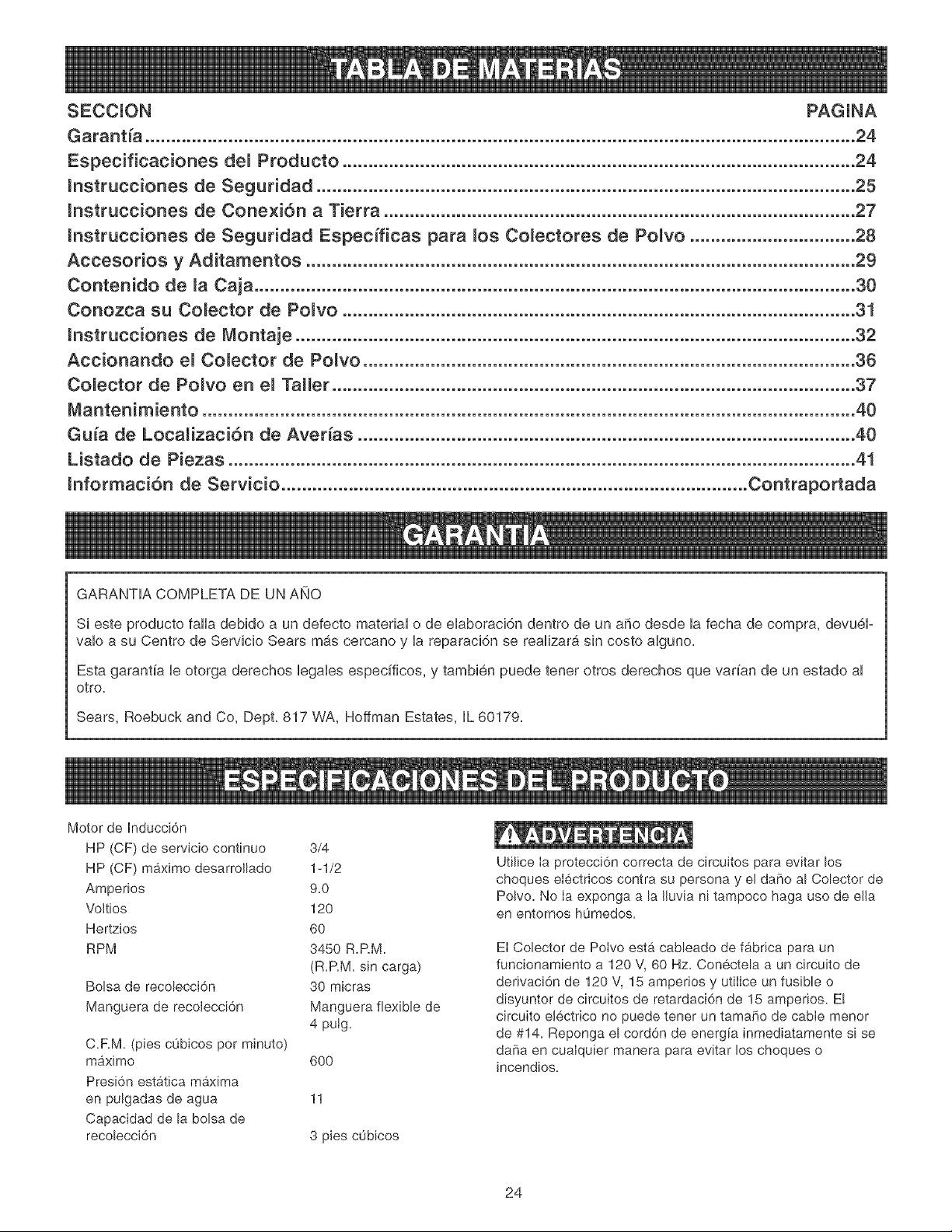
g. UT_LJCE PROTECCION OCULAR SlEMPRE. Cuatquier
herramienta mecb,nica es capaz de expuisar escombros
hacia los ojos dei usuario durante ias operaciones, io que
puede ocasionar da_io ocuHar grave y permanente. Las
gafas de use cotidiano NO son gafas de seguridad.
Utilice Gafas de Seguridad (que cumptan con Ia normati-
va Z87.1 de ANSi) SlEMPRE cuando vaya a hacer use
de herramientas mec_.nicas. Las Gafas de Seguridad
estan disponibHes en Hastiendas de ventas al detal de
Sears.
ANTES DE UTlUZAR EL COLECTOR DE
POLVO
Para evitar las hendas graves y eI dafio a la herramienta, Iea
y obedezca todas Ias instrucciones de Seguridad y Operaci6n
antes de operar el Colector de Polvo.
1. LEA a consciencia el Manual del Propietario. APRENDA
c6mo hacer use de esta herramienta para sus aplica-
ciones disehadas.
2. CONECTE TODAS LAS HERRAMIENTAS A TJERRA.
Si la herramienta se suministra con un enchufe de 3
roaches, se le debe enchufar a un tomacorrientes que
disponga de 3 contactos electricos. El tercer macho se
utiliza para conectar Ia herramienta a tierra y ofrecer
protecciOn contra los cheques etectricos accidentaHes.
NO quite el tercer macho. Vea HasInstrucciones de
Conexi6n a Tierra.
10.
11.
12.
13.
UT_MCE PROTECCK_N AUDJTIVA SIEMPRE. El algo-
dOn com0n no constitwe un dispositivo aceptabte de pro-
tecciOn. El equipo auditivo debe cumplir con Hasnormati-
vas S&19 de ANSL
SIEMPRE DESENCHUFE LA HERRAMIENTA DEL
TOMACORRJENTES cuando vaya a realizar ajustes,
cambiar piezas o realizar cualquier chase de
mantenimiento.
MANTENGA LOS ESCUDOS DE PROTECCION EN SU
SITIO Y EN BUEN ESTADO DE FUNCIONAMIENTO.
EV_TE EL ARRANQUE ACCIDENTAL Asegurese de
que el interruptor de potencia se encuentre en la posiciOn
de "APAGADO" antes de enchufar el cord6n de potencia
en el tomacorrientes.
3. EVITE UN ENTORNO LABORAL PELIGROSO. NO
utilice las herramientas el0ctricas en un entorno h0medo,
ni tampoco bs exponga a Iluvia.
4. NO utilice herramientas el0ctricas si hay gases o liquidos
infiamabbs presentes.
5. MANTENGA SJEMPRE su zona de trabajo limpia, bien
alumbrada y organizada. NO TRABAJE en un entorno
con superficies de piso resbalosas a consecuencia de Hos
escombros, la grasa y Hacera.
6. MANTENGA ALEJADOS A LOS NtNOS Y WSITANTES.
NO permita que haya personas en Hazona inmediata de
trabajo, particuiarmente cuando Haherramienta el0ctrica
se encuentre en funcionamiento.
7.
8.
NO FUERCE LA HERRAMIENTA a reaHizar operaciones
para las cuabs no fue disehada. Realizara una labor mas
segura y de meier calidad si se Heutiliza solamente para
realizar operaciones para Ias cuales fue diseSada.
UTJUOE VESTJMENTA APROPIADA. NO vista ropa
hoHgada, guantes, corbatas ni art[culos de joyer[a. Estos
art[cu!os pueden quedar atrapados en la m&quina
durante Hasoperaciones y tirar del operario, atrayendoHo
hacia bs piezas en movimiento. El usuario debe Ibvar
una cubierta protectora sobre eI cabeIHo, si tiene
cabeiiera larga, para impedir el contacto con cualquier
pieza en movimiento.
14.
15.
16.
17.
18.
19.
20.
QU_TE TODAS LAS HERRAM_ENTAS DE MANTENF
M_ENTO de la zona inmediata antes de encender Ha
herramienta.
SOLO UTiLICE ACCESORIOS RECOMENDADOS. Ei
use de accesorios incorrectos o poco apropiados puede
ocasionar heridas graves al operario y ocasionar dare a
la herramienta. Si tiene dudas, consuite el manual de
instrucciones que se adiunta con el accesorio especifico.
JAMAS DEJE UNA HERRAMIENTA EN FUNCIONAo
MIENTO S_N ATENDER Conmute e! interruptor de
energ[a a la posici6n de apagado. NO abandone Haherra-
mienta hasta que esta se haya detenido per complete.
NO SE PARE SOBRE LA HERRAMIENTA. Pueden pro-
ducirse heridas graves si la herramienta se vuelca o si
usted hace contacto con la herramienta accidentalmente.
NO ALMACENE nada per encima ni cerca de Hamaquina
en deride alguien pueda intentar pararse en la herra-
mienta para alcanzarlo.
MANTENGA SU EQUILJBR!O. NO se extienda sobre la
herramienta. Haga uso de zapatos con sueb de caucho
resistente al aceite. Mantenga el piso libre de escombros,
grasa o cera.
MANTENGA SUS HERRAM_ENTAS CU_DADOSA-
MENTE. Mantenga sus herramientas Iimpias yen buen
estado. Mantenga afiladas todas las hoias y brocas.
25
21. REVISE SI HAY PIEZAS DANADAS ANTES DE CADA
USO DE LA HERRAMIENTA. Revise todos los protec-
tores cuidadosamente para comprobar que funcionan
correctamente y que no estan daffados, y que realizan
sus funciones diseffadas correctamente. Revise el
alineamiento, la fijaci6n o la ruptura de Ias piezas en
movimiento. Cualquier protector u otra pieza que se
encuentre daffada debe repararse o reemplazarse
[nmediatamente.
22. HAGA SU TALLER A PRUEBA DE NtNOS quitando las
Ilaves del interruptor, desenchufando Ias herramientas de
los tomacordentes, y mediante el uso de candados.
23. NO OPERE LA HERRAMIENTA BAJO LA tNFLUENCIA
DE LAS DROGAS O DEL ALCOHOL.
24. AFIANCE TODO EL MATERIAL. Siempre que resulte
posible, utilice abrazaderas o plantilias para asegurar el
material. Esto ofrece mayor seguridad que intentar
sujetar el material con sus propias manos.
25. MANTENGASE ALERTA, ESTE CONSCIENTE DE LO
QUE HACE, Y UTILICE SENTIDO COMUN CUANDO
VAYA A OPERAR UNA HERRAMIENTA ELECTRICA,
NO UTILICE LA HERRAMIENTA Sl ESTA CANSADO O
BAJO LA INFLUENCIA DE DROGAS, ALCOHOL O
MEDICAMENTOS. Un momento de descuido durante el
uso de herramientas electricas puede resuttar en
lesiones personales graves.
26. UTILICE SIEMPRE UNA CARETA PARA PREVENIR LA
ASPIRAClON DE POLVO PELIGROSO O PARTiCULAS
AE_REAS, incluyendo polvo de madera, poivo de silice
cristatino y potvo de asbesto. Aleje Ias parffculas de la
cara y et cuerpo. Opere la herramienta siempre en un
sit[o con buena ventiIaci6n y proporcione la extracci6n
adecuada deI poIvo. Utilice sistemas de recolecci6n de
poIvo siempre que sea posible. La exposici6n al polvo
puede resultar en heridas graves y permanentes al sis-
tema respirator[o o de otros tipos, [ncluyendo la siJicosis
(una enfermedad pulmonar grave), cAncer y Ia muerte.
Evite aspirar el poIvo y evite el contacto proIongado con
el poIvo. El permitir que et polvo penetre dentro de su
boca u ojos, o que permanezca sobre su piel, puede pro-
mover la absorci6n de material da[iino. Utilice siempre
protecci6n respiratoria adecuada y aprobada por
NIOSH/OSHA con ajuste correcto, y lave las zonas
expuestas con agua y jab6n.
27. UTILICE UNA EXTENSION ELECTRICA CORRECTA Y
EN BUEN ESTADO. Cuando vaya a hacer uso de una
extensJ6n electrica, aseg0rese de utilizar una que sea 1o
sufic[entemente fuerte como para transportar Ia cordente
a ser utilizada por su herramienta. Tenga Ia bondad de
referirse al cuadro de calibres recomendados (AWG)
para las extensiones electricas para el dimensionamiento
correcto de la extensi6n electrica. S[ tiene dudas, utiJice
la siguiente extensi6n de mayor calibre.
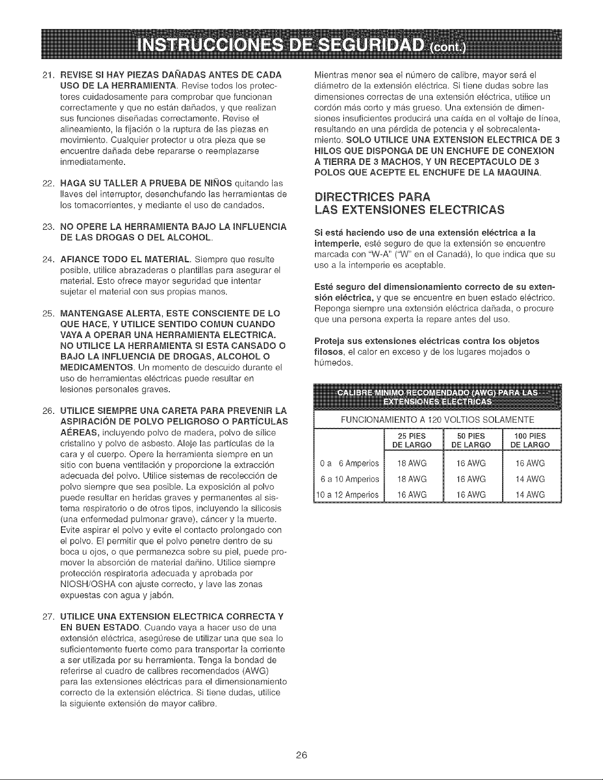
Mientras menor sea eI n0mero de calibre, mayor sera el
diAmetro de la extensi6n electrica. Si tiene dudas sobre las
dimensiones correctas de una extensi6n eIectrica, utiIice un
cord6n mas corto y mas grueso. Una extensi6n de dimen-
siones insuficientes producira una ca[da en el voltaje de ffnea,
resuItando en una perdida de potencia y el sobrecalenta-
miento. SOLO UTIL[CE UNA EXTENSION ELECTR[OA DE 3
HILOS QUE D[SPONGA DE UN ENCHUFE DE CONEXION
A TJERRA DE 3 MACHOS, Y UN RECEPTACULO DE 3
POLOS QUE ACEPTE EL ENCHUFE DE LA MAQUINA.
D[RECTRICES PARA
LAS EXTENSIONES ELECTRICAS
Si estA haciendo uso de una extensi6n el_ctrlca a [a
intemperle, est6, seguro de que [a extensi6n se encuentre
marcada con "W-A" ("W" en el CanadA), Io que indica que su
uso a la intemperie es aceptable.
Est6 seguro de[ dirnensionamiento correcto de su exten-
si6n el_ctrica, y que se encuentre en buen estado eiectrico.
Reponga siempre una extensi6n electrica daffada, o procure
que una persona experta Ia repare antes del uso.
Proteja sus extensiones electricas contra los objetos
filosos, el calor en exceso y de los lugares mojados o
humedos.
FUNCIONAMIENTO A 120 VOLTIOS SOLAMENTE
0 a 6Amperios
6 a 10Amperios
10 a 12 Amperios
25 P(ES
DE LARGO
18 AWG
18 AWG
16 AWG
50 PIES
DE LARGO
16 AWG
16 AWG
16 AWG
100 PIES
DE LARGO
16 AWG
14 AWG
14 AWG
26
ESTA HERRAM_ENTA DEBE ESTAR CONECTADA A T_ERRA
DURANTE EL USO PARA PROTEGER AL OPERARJO DE
LOS CHOQUES ELECTRJCOS.
EN EL CASO DE UN MALFUNCIONAMJENTO O AVERIA, la
conexi6n a tierra ofrece el trecho de menor resistencia para Ia
corriente el6ctrica y reduce el riesgo de los choques el6ctri-
cos. Esta herramienta viene equipada con un cord6n eIectrico
que dispone de un conductor de conexi6n a tierra para el
equipo asf como un enchufe de conexi6n a tierra. El enchufe
DEBE estar enchufado a un tomacorrbntes adaptado que
haya sido correctamente instalado y conectado a tierra de
acuerdo con TODOS los c6digos y ordenanzas municipales.
NO MODIFJQUE EL ENCHUFE SUMJNJSTRADO. Haga que
un electricista calificado instale el tomacornentes apropiado si
el enchufe no cabe en el tomacorrientes.
LA CONEXION ELECTRICA _NCORRECTA del conductor de
conexi6n a tJerra para el equipo puede resultar en el riesgo
de choques eJectricos. El conductor con el aislamiento verde
(con o sin rayas amarillas) es el conductor de conexi6n a
tierra para el equipo. NO conecte el conductor de conexi6n a
tierra para el equipo a una terminaci6n viva si resulta nece-
sario reparar o reemplazar el cord6n el6ctrico o el enchufe.
CONSULTE con un ebctricbta calJficado o personaJ de
servicio si no entiende tas instrucciones de conexi6n a tierra
compietamente, o si no esta seguro que la herramienta esta
debidamente conectada a tierra.
El motor suministrado con su Colector de PoJvo es un motor
monofasico de 120 voJtios. Se envfa cabIeada para el fun-
cionamiento a 120 voltios. Jamas conecte el aIambre verde a
un terminal vivo.
SOLO UTJUCE UNA EXTENSION ELECTR_CA DE 3 NJLOS
QUE DISPONGA DE UN ENCNUFE DE CONEX_ON A
TIERRA DE 3 MACHOS, Y UN RECEPTACULO DE 3
POLOS QUE ACEPTE EL ENCNUFE DE LA MAQU_NA.
REPONGA CUALQUtER CORDON DANADO O GASTADO
tNMEDJATAMENTE.
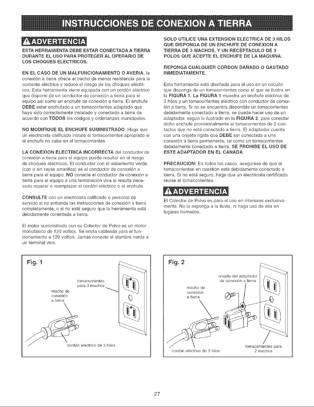
Esta herramienta estb_dise[iada para el uso en un circuito
que disponga de un tomacorrientes como el que se iIustra en
la FIGURA 1. La RGURA 1 muestra un enchufe el6ctrico de
3 hilos y un tomacorrientes ei6.ctrico con conductor de conex-
i6n a tierra. Si no se encuentra disponibIe un tomacorrientes
debidamente conectado a tierra, se puede hacer uso de un
adaptador, seg0n Io ilustrado en Ia FIGURA 2, para conectar
dicho enchufe provisionalmente al tomacorrientes de 2 con-
tactos que no est_ conectado a tierra. El adaptador cuenta
con una orejeta r[gida que DEBE ser conectada a una
conexi6n a tierra permanente, tal como un tomacorrientes
debidamente conectado a tierra. SE PRONJBE EL USO DE
ESTE ADAPTADOR EN EL CANADA.
PRECAUCION: En todos los casos, aseg0rese de que ei
tomacorrientes en cuesti6n este debidamente conectado a
tierra. Si no estb, seguro, haga que un ebctricista certificado
revise el tomacorrientes.
El Cobctor de Poivo es para el uso en interiores exclusJva-
mente. No la exponga a Ja JJuvia, ni haga uso de ella en
Jugares humedos.
Fig. 1
tomacorrientes
para 3 machos
macho de
conexi6n
a tierra
.__ electrico de 3 hilos
Fig. 2
macho de
conexi6n
a tierra
cord6n electrico de 3 hilos
orejeta de! adaptador
de conexi6n a tierra
tomacorrientes para
2 machos
27
JNSTRUCCJONES DE SEGURJDAD
ESPECJNCAS PARA LOS
COLECTORES DE POLVO
El funcionamiento de cualquier colector de polvo puede tener
come consecuencia la expulsi6n de escombros hacia sus
ojos, Io que puede resuitar en heridas oculares graves.
UTILiOE SlEMPRE Gafas de Protecci6n (que cumplan con Ia
normativa Z87.1 de ANSi) cuando vaya a hacer use del
colector de polvo. Las Gafas de Seguridad est_in disponibles
en las tiendas Sears de ventas al detaL Mantenga los puF
gares y los dedos alejados de los puertos de admisi6n.
Las precauciones basicas deben acatarse en todo momento
cuando se utiliza un colector de polvo. Cumpla con las
instrucciones indicadas a continuaci6n para reducir el riesgo
de lesiones, cheques electricos o incendios:
1. LEA y entienda el manual de instrucciones antes de
poner el colector de polvo en funcionamiento.
2. NO OPERE ESTA MAQUiNA hasta que se encuentre
ensamblada e instaIada conforme alas instrucciones.
3. ASESORESE CON SU SUPERVISOR, instructor u otra
persona experta si no esta familiarizado con el uso de
esta mb,quina.
12. UTlUCELO s61o como se describe en este manual
SOLO utilice los accesofios recomendados per Sears.
13.
NO tire de[ colector de polvo mediante el cord6n de
energia. JAMAS permita que el cord6n de potencia entre
en contacto con bordes filosos, superficies calientes,
aceite o grasa.
14. NO desenchufe el colector de poIvo tirando del cord6n de
energia. SlEMPRE agarre el enchufe en vez deI cord6n.
15. REPONGA un cord6n daF_ado inmediatamente. NO utiF
ice un cord6n o enchufe que est6n daffados. Si el colec-
tor de polvo no funciona debidamente, o si ha sido daffa-
do, dejado a Ia intemperie o si ha entrado en contacto
con el agua, devu61valo a un Centre de Servicio Sears
para recibir servicio.
16. NO utiIice ei colector de polvo como juguete. NO LO
UTILJCE si hay niffos presentes.
17.
NO inserte los dedos o cuerpos extraffos dentro del
puerto de entrada de polvo. Debe alejar el cabello, Ia
ropa holgada, Ios dedos y demAs extremidades de las
aberturas y piezas en movimiento del colector de poIvo.
18. NO utiIice el colector de polvo sin que Ia bolsa guarda-
polvo se encuentre en su sitio y debidamente asegurada.
4.
NO PERMITA el colector de polvo permanezca enchufa-
do al tomacorrientes. El colector de polvo debe desen-
chufarse del tomacorrientes cuando no se encuentre en
use y antes de rendir servicio, cambiar bolsas, destupir y
Hmpiar,
5. COLOQUE SIEMPRE el interruptor de energia en
"APAGADO" antes de desenchufar el colector de polvo.
6. PARA REDUCIR EL RiESGO DE CHOQUES ELECTRI-
COS, no utilice [a maquina a [a intemperie. No la expon-
ga a la Iluvia. Aimac6neia baio techo. Utiffcela para
recoger materiaI seco soJamente.
7.
OBEDEZCA todos los c6digos el6ctricos y de seguridad,
incluyendo e! C6digo EI6ctrico Nacional (NEC) y las
Normas de Satud y Seguridad en el Trabajo (OSHA).
Todas Ias conexiones y cableado el6ctrico deben ser
realizados s61o per personal competente.
8. NO maneje et enchufe ni el colector de polvo con las
manes mojadas.
9.
NO UTILICE el colector de polvo para recoger ffquldos
infiamables o combustibles, tales como Ia gasolina.
JAMAS utilice et colector de polvo cerca de cualquier
ffquido inflamable o combustible.
10. UTILICE el colector de polvo para recoger materlales de
madera sotamente. NO LO UTILICE para recoger viru-
tas, poivo nl piezas de metal.
19.
UTIUOE SIEMPRE compuertas de seguridad para cubrir
los puertos de poIvo cuando el colector de polvo no se
encuentre en use o cuando se esta montado sobre una
superficie de apoyo para el almacenamiento.
20.
La bolsa guardapolvo debe ser JNSPECCIONADA PERIO-
DJOAMENTE per si exlste cualquier cortadura, desgarre
o rompedura. JAMAS opere el colector de potvo con una
bolsa o manguera de vac[o que este daFiada.
21. El colector de potvo SOLO esta diseF_ado para el use
domestico o el uso industrial ligero.
22. CONECTE el colector de polvo a un tomacorrientes
debidamente conectado a tierra. Vea las instrucciones de
conexi6n a tierra.
23. INFORMACION ADICIONAL sobre el funcionamiento
seguro y correcto de este producto esta disponible de
parte del National Safety Council, 1121 Spring Lake
Drive, Itasca, IL 60143-3201 en el Manual de Prevenci6n
de Accidentes para Operaclones Industriales as[ come en
las Hojas de Datos de Seguridad suministradas per et
NSC. Tenga Ia bondad de referlrse tambien aI ANSI 01.1,
RequisJtos de Seguridad para la Maquinaria de
Ebanister[a de la American National Standards Institute, y
el Reglamento 1910.213 OSHA del U.S. Department of
Labor.
24. GUARDE ESTAS JNSTRUCCIONES. Refi6rase a elias
con frecuencia y utilicelas para instruir a otros usuarios_
11. JAMAS utilice el colector de pelves para disipar emana-
clones o humo. JAMAS recoja cualquier cosa que este
ardiendo o emitiendo humo, as[ como cigarrillos, f6sforos
o cenizas calientes.
28

ACCESOFHOS DJSPONJBLES
Visite su Departamento de Ferreteffa de Sears o consulte el
Catalogo de Herramientas EI6ctricas y de Mane de Sears
para los siguientes accesorios:
ARTJCULO
Bolsa de fiRro de 30 micras
NUMERO DE EXISTENCJA
21374
Manguera flexible 4 pulg. diametro
x 10 pies
Manguera flexible 4 pulg. diametro
x 25 pies
Conectores de accesorJos varies
21372
21373
Consultar el
catatogo o la
tienda
Sears podra recomendar otros accesorios no listados en este
manual.
ConsuRe su Departamento de Ferreterfa de Sears mas
cercano o el Catalogo de Herramientas Ebetricas y de Mano
de Sears para otros accesorios.
No utilice ning0n accesorio a menos que haya Ie{do cabal-
mente eJ Manual deJ Propietario para dicho accesorio.
S61o utilice accesorios recomendados para este Cobctor de
Polvo. El use de otros accesorios puede ocasionar bsiones
graves y producir daBo al CoJector de Polvo.
29
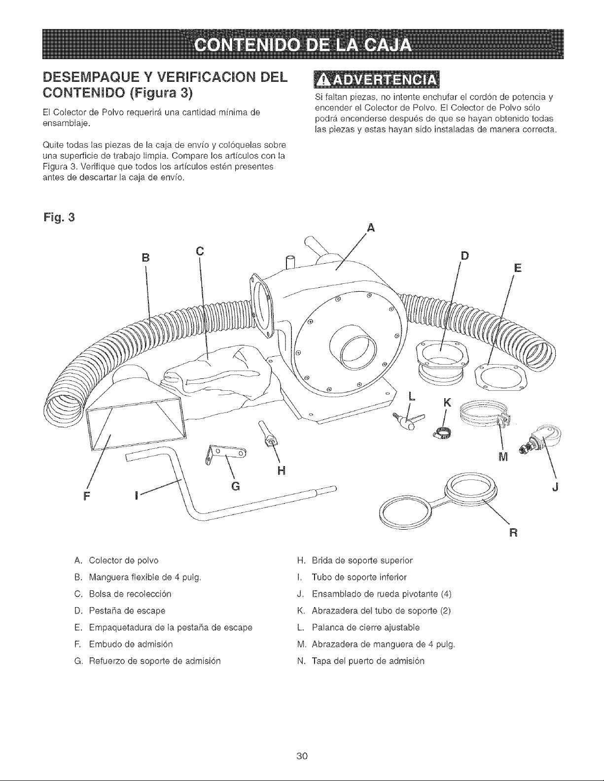
DESEMPAQUE Y VEFIJFJCACJON DEL
CONTENJDO (Figura 3}
El Colector de Polvo requerira una cantidad mfnima de
ensambIaje.
Quite todas Ias piezas de la caja de env[o y coI6quelas sobre
una superficie de trabajo Iimpia. Compare los art[culos con Ia
Figura 3. Verifique que todos los art[culos esten presentes
antes de descartar la caja de env[o.
Si faltan piezas, no intente enchufar el cord6n de potencia y
encender e! Colector de Polvo. El Colector de Polvo s6Io
podr_i encenderse despues de que se hayan obtenido todas
las piezas y estas hayan sido instaladas de manera correcta.
Fig. 3
B
C
A
E
/
F
J
A. Colector de polvo
B. Manguera flexible de 4 pulg.
C. Bolsa de recolecci6n
D. Pesta_a de escape
E. Empaquetadura de Ia pestafla de escape
F. Embudo de admisi6n
G. Refuerzo de soporte de admisi6n
H. Brida de soporte superior
I. Tubo de soporte inferior
J. Ensamblado de rueda pivotante (4)
K. Abrazadera del tubo de soporte (2)
h Palanca de cierre ajustable
M. Abrazadera de manguera de 4 pulg.
N. Tapa del puerto de admisi6n
3O

Fig. 4 D
G
E
F
B
A. Puerto de admisi6n de 4 putg.
B. Manguera flexible de 4 pulg.
C. Tapa del puerto de admisi6n
D. Embudo de entrada
E. Vara de soporte
R Puerto de escape de 4 pulg.
G. Bolsa de recolecci6n
H. Colector de polvo
I. Base
J. Rueda pivotante
31

2.
3.
NO inicie ei ensamUaje hasta que este seguro de que la
herramienta NO ESTA enchufada.
NO ensamble eI Colector de Potvo hasta que este seguro
de que el interruptor de energfa se encuentre en la posi-
ci6n de "APAGADO".
Para su propia seguridad, NO CONECTE Ia m_.quina a
la fuente de energfa hasta que la maquina se encuentre
completamente ensamblada y usted haya Ie[do y
entendido cabalmente el Manuel del Propietario.
Fig. 6
\
D
C
MONTAJE DE LAS RUEDAS
PJVOTANTES A LA BASE
ASEGURESE DE QUE EL COLECTOR DE POLVO ESTE
DESCONECTADO DE LA FUENTE DE ENERGIAo
1. Coloque el colector de polvo sobre su costado.
3.
4.
Coloque una tuerca de pestaha hexagonal de 3/8-16 (C)
sobre el perno (D) de la rueda pivotante y apriete.
Consulte la figura 6.
Repita los Pasos 2, 3 y 4 arriba para montar !os ensam-
blados de rueda pivotante restantes a la base.
Fig. 5
A
MONTAJE DE LA PESTANA
DE ESCAPE
ASEGURESE DE QUE EL COLECTOR DE POLVO ESTE
DESCONECTADO DE LA FUENTE DE ENERGIA,
/
/
2. hserte el perno del ensamblado de Ia rueda pivotante a
traves de cada uno de los cuatro agujeros (A) en la base
del colector de polvo. Consulte la figura 5.
1. Alinee los agujeros en la pestafia de escape (A) con los
agujeros en la empaquetadura de la pestaha de escape
(B). Consulte la figura 7.
32
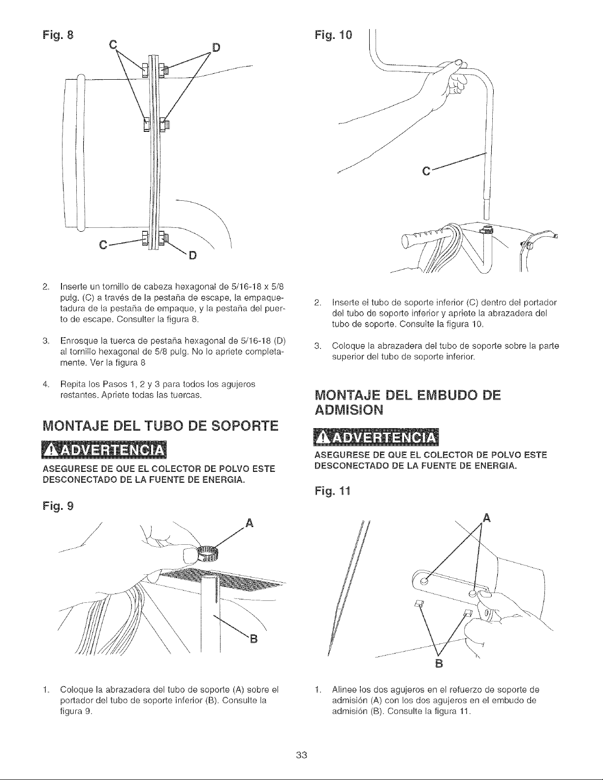
Fig. 8 Fig. 10
C D
2=
3=
4=
Inserte un tornillo de cabeza hexagonal de 5/16-18 x 5/8
pulg. (C) a traves de la pestaha de escape, la empaque-
tadura de Ia pestafia de empaque, y la pestaha del puer-
to de escape. Consulter la figura 8=
Enrosque la tuerca de pesta5a hexagonal de 5/16-18 (D)
al tornilIo hexagonal de 5/8 pulg= No Io apriete completa-
mente= Ver la figura 8
Repita los Pasos 1,2 y 3 para todos los agujeros
restantes. Apriete todas las tuercas.
2=
3=
Inserte eI tubo de soporte inferior (C) dentro dei portador
del tube de soporte inferior y apriete la abrazadera del
tube de soporte= Consulte la figura 10=
Coloque la abrazadera dei tubo de soporte sobre la parte
superior del tube de soporte inferior.
MONTAJE DEL EMBUDO DE
MONTAJE DEL TUBO DE SOPORTE
ASEGUFtESE DE QUE EL COLECTOFt DE POLVO ESTE
DESCONECTADO DE LA FUENTE DE ENERG_Ao
Fig. 9
A
ASEGURESE DE QUE EL COLECTOR DE POLVO ESTE
DESCONECTADO DE LA FUENTE DE ENERGIA,
Fig. 11
A
\\
\\
B
1. Co!oque la abrazadera del tube de soporte (A) sobre el
portador del tube de soporte inferior (B). Consutte la
figura 9=
1. Alinee Ios dos agujeros en el refuerzo de soporte de
admisi6n (A) con !os dos agujeros en el embudo de
admisi6n (B). Consulte la figura 11.
33
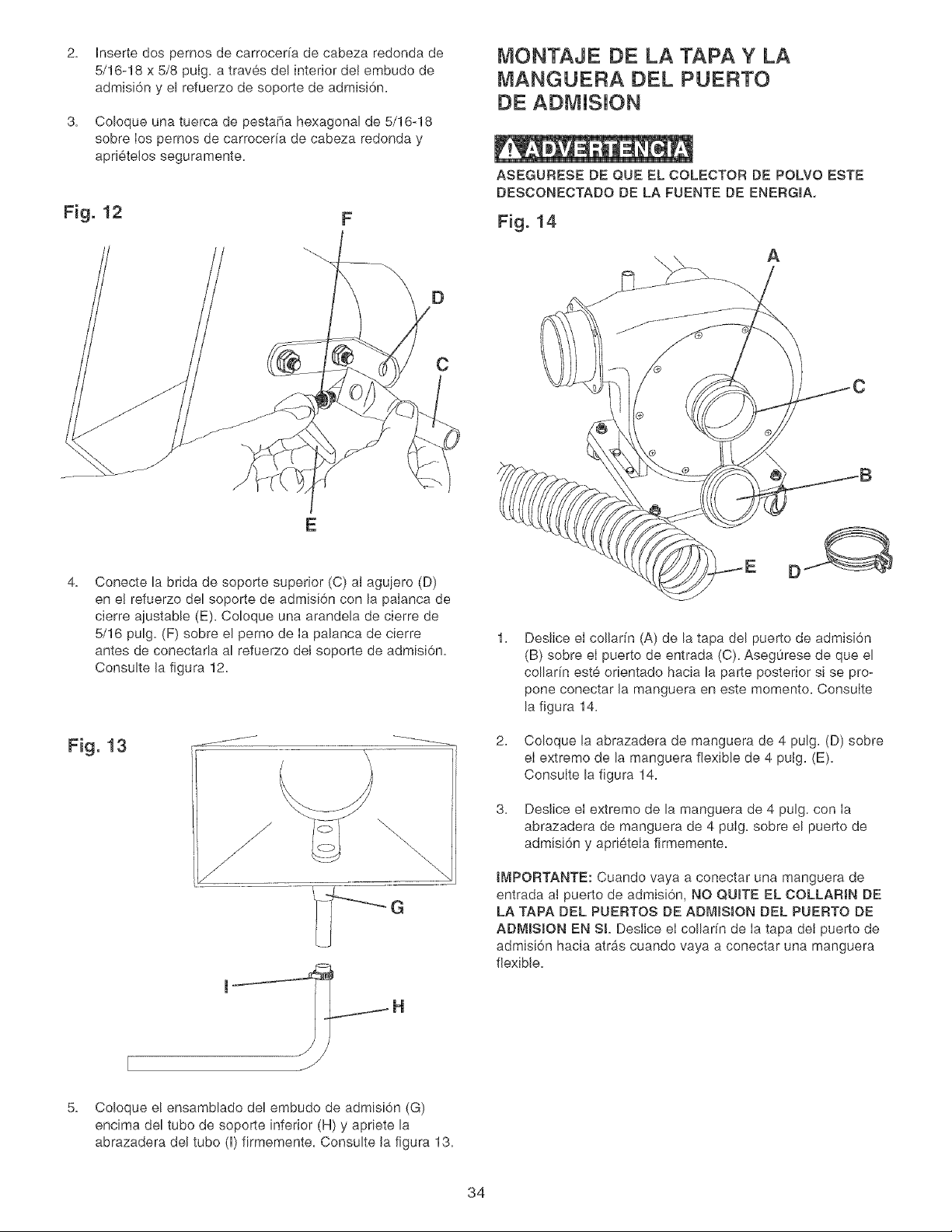
2=
3=
hserte dos pernos de carrocer[a de cabeza redonda de
5/16-18 x 5/8 puIg. a traves del interior de! embudo de
admisi6n y el refuerzo de soporte de admisi6n.
Coloque una tuerca de pesta_a hexagonal de 5/16-18
sobre Ios pernos de carrocerfa de cabeza redonda y
apri6telos seguramente.
F
D
C
MONTAJE DE LA TAPA Y LA
MANGUERA DEL PUERTO
DE ADMJSJON
ASEGURESE DE QUE EL COLECTOR DE POLVO ESTE
DESCONECTADO DE LA FUENTE DE ENERGIA,
Fig. 14
A
E
4=
Conecte la brida de soporte superior (C) aJagujero (D)
en el refuerzo del soporte de admisi6n con la paIanca de
cierre ajustable (E). Co!oque una arandela de cierre de
5/16 pulg. (F) sobre el perno de Ia palanca de cierre
antes de conectada al refuerzo del soporte de admisi6n.
Consulte Ja figura 12.
Fig. 13 j/ \
G
1=
DesJice el collar[n (A) de la tapa del puerto de admisi6n
(B) sobre el puerto de entrada (C). Asegurese de que el
collar[n este orientado hacia la parte posterior si se pro-
pone conectar Ja manguera en este memento. ConsuIte
la figura 14.
2. Coloque la abrazadera de manguera de 4 pulg. (D) sobre
el extreme de la manguera flexible de 4 putg. (E).
Consulte la figura 14.
3. Deslice el extremo de la manguera de 4 pulg. con Ia
abrazadera de manguera de 4 pulg. sobre el puerto de
admisi6n y apri6tela firmemente.
tMPORTANTE: Cuando vaya a conectar una manguera de
entrada aJ puerto de admJsi6n, NO QUITE EL COLLARtN DE
LA TAPA DEL PUERTOS DE ADMISJON DEL PUERTO DE
ADM_SION EN SL Deslice ei collarfn de ia tapa dei puerto de
admisi6n hacia atras cuando vaya a conectar una manguera
flexibJe.
J
5. Coloque el ensamblado del embudo de admisi6n (G)
encima del tube de soporte inferior (H) y apriete la
abrazadera del tubo (I) firmemente. Consulte Ja figura 13.
34
G
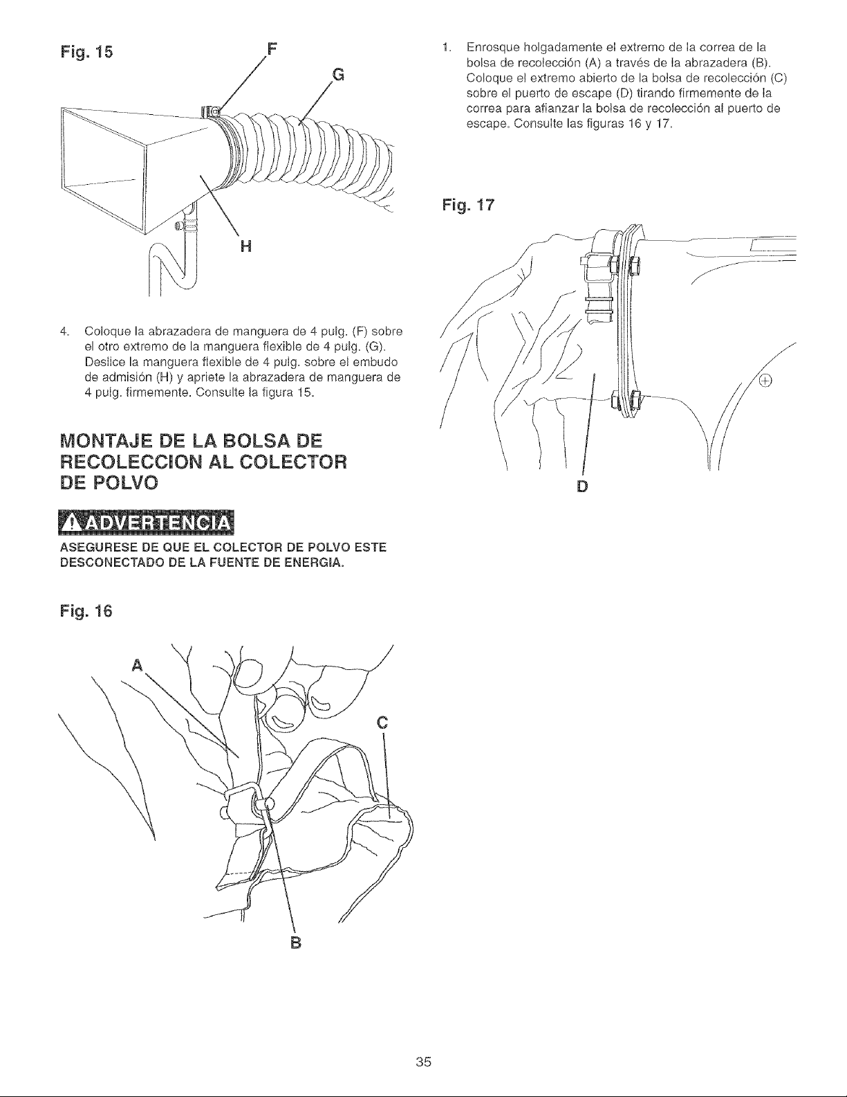
1.
Enrosque holgadamente el extremo de Ia correa de la
bolsa de recolecci6n (A) a traves de Ia abrazadera (B).
Coloque e! extremo abierto de la bolsa de recolecci6n (C)
sobre el puerto de escape (D) tirando firmemente de Ia
correa para afianzar la botsa de recolecci6n al puerto de
escape. Consulte las figuras 16 y 17.
4.
H
Coloque la abrazadera de manguera de 4 pulg. (F) sobre
el otro extreme de la manguera flexible de 4 pulg. (G).
Deslice la manguera flexible de 4 pulg. sobre el embudo
de admisi6n (H) y apriete la abrazadera de manguera de
4 pulg. firmemente. Consulte la figura 15.
Fig. 17
MONTAJE DE LA BOLSA DE
RECOLECCION AL COLECTOR
DE POLVO
D
ASEGURESE DE QUE EL COLECTOR DE POLVO ESTE
DESCONECTADO DE LA FUENTE DE ENERGIA.
Fig. 16
A
C
B
35
PARA LA SEGURIDAD DEL OPERARIO, mantenga los
dedos y todos los cuerpos extrahos fuera de los puertos de
admisi6n. El acceso a! ventilador girante dentro de la caja deI
soplador es posible a traves de los puertos de admisi6n yes
peligroso. No utilice vestimenta hoigada ni artfcutos de
joyerfa. Asegurese de que cada puerto de admisi6n que no
este en uso, o conectado a un sistema de recolecci6n de
polvo, se encuentre cubierto por una tapa de puerto de
admisi6n.
CONECTANDO LA HERRAMIENTA A
LA FUENTE DE ENERGIA
Debe utilizar un circuito electrico independiente para sus
herramientas. Este circuito no debe ser menor que el alambre
#14 A.W.G. y debe estar protegido por un fusible de retar-
daci6n de 15 Amperios. Haga que un electricista competente
reponga o repare inmediatamente cuatquier cord6n des-
gastado. Antes de conectar el motor a Ia I[nea de energfa,
asegurese de que el interruptor este en Ia posici6n de
APAGADO y asegurese de que la corriente electrica sea de
las mismas caracterfsticas que Io indicado por la placa de
notaciones del motor. Todas las conexiones de I[nea deben
hacer buen contacto. El funcionamiento a bajo voltaie
perjudicara el motor.
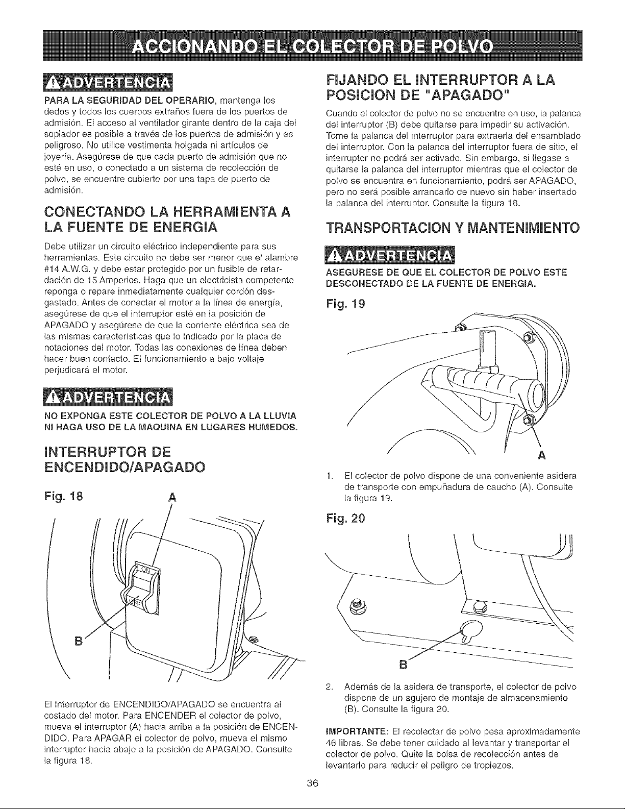
FIJANDO EL INTERRUPTOR A LA
POSlCION DE "APAGADO"
Cuando el colector de polvo no se encuentre en uso, la palanca
del interruptor (B) debe quitarse para impedir su activaci6n.
Tome Ia palanca del interruptor para extraerla del ensamblado
deI interruptor. Con Ia palanca deI interruptor fuera de sitio, el
interruptor no podra ser activado. Sin embargo, si Ilegase a
quitarse Ia palanca de! interruptor mientras que el colector de
potvo se encuentra en funcionamiento, podra ser APAGADO,
pero no sera posible arrancarlo de nuevo sin haber insertado
la palanca del interruptor. Consulte la figura 18.
TRANSPORTACION Y MANTENIMIENTO
ASEGURESE DE QUE EL COLECTOR DE POLVO ESTE
DESCONECTADO DE LA FUENTE DE ENERGIA,
Fig. 19
NO EXPONGA ESTE COLECTOR DE POLVO A LA LLUVIA
NI HAGA USO DE LA MAQUINA EN LUGARES HUMEDOS.
INTERRUPTOR DE
ENCENDIDO/APAGADO
Fig. 18 A
/
\
El interruptor de ENCENDIDO/APAGADO se encuentra al
costado del motor. Para ENCENDER el colector de polvo,
mueva el interruptor (A) hacia arriba a Ia posici6n de ENCEN-
DIDO. Para APAGAR et colector de polvo, mueva el mismo
interruptor hacia abajo a la posici6n de APAGADO. Consulte
la figura 18.
A
1. El cotector de polvo dispone de una conveniente asidera
de transporte con empuF_adura de caucho (A). Consulte
la figura 19.
Fig. 20
B
2. Ademas de la asidera de transporte, el colector de polvo
dispone de un aguiero de montaje de almacenamiento
(B). Consulte la figura 20.
tMPORTANTE: El recolectar de polvo pesa aproximadamente
46 libras. Se debe tener cuidado al Ievantar y transportar el
colector de polvo. Quite la bolsa de recolecci6n antes de
levantarlo para reducir el peligro de tropiezos.
36
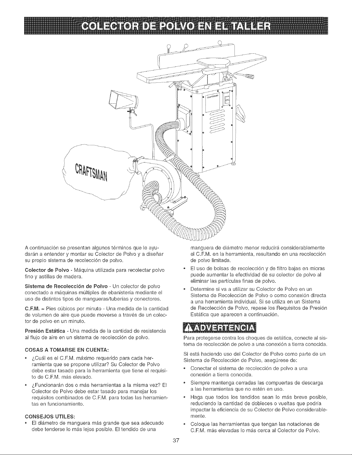
A continuaci6n se presentan aIgunos terminos que le ayu-
daran a entender y montar su Colector de Polvo y a diseBar
su propio sistema de recolecci6n de potvo.
OoBeetor de Polvo - Maquina utiJizada para recolectar polvo
fine y astillas de madera.
Sistema de Recomecci6n de Potvo - Un coiector de polvo
conectado a maquinas m0ItipIes de ebanister[a mediante el
use de distintos tipos de mangueras/tuber[as y conectores.
CoF,M, = Pies cObicos per minuto - Una medida de la cantidad
de voIumen de aire que puede moverse a traves de un colec-
tor de potvo en un minuto.
Presi6n Est_tica - Una medida de la cantidad de resistencia
aI flujo de aire en un sJstema de recolecci6n de polvo.
COSAS A TOMARSE EN CUENTA:
_,Cu&Jes el C.RM. maximo requerido para cada her-
ramienta que se propone utiJizar? Su Colector de Polvo
debe estar tasado para Ia herramienta que tiene el requisi-
to de C.RM. m_.s elevado.
o _,Funcionaran dos o mas herramientas a la misma vez? El
Colector de Polvo debe estar tasado para manejar los
requisites combinados de C.RM. para todas Jas herramien-
tas en funcionamiento.
CONSEJOS UTILES:
El di_metro de manguera mas grande que sea adecuado
debe tenderse Io mas lejos posible. El tendido de una
37
manguera de diametro menor reducira considerablemente
el C.RM. en la herramienta, resultando en una recolecci6n
de polvo limitada.
El use de botsas de recolecci6n y de filtro bajas en micras
puede aumentar ia efectividad de su colector de polvo al
eliminar las part[culas finas de polvo.
Determine sJ va a utilizar su Colector de Polvo en un
Sistema de Recolecci6n de Polvo o come conexi6n directa
a una herramienta individual Si se utiliza en un Sistema
de Recolecci6n de Polvo, repase los Requisites de Presi6n
Estatica que aparecen a continuaci6n.
Para protegerse contra ios choques de estatica, conecte al sis-
tema de recolecci6n de polvo a una conexi6n a tierra conocida.
Si est_ haciendo uso det Colector de Polvo como parte de un
Sistema de RecoIecci6n de Polvo, aseg0rese de:
Conectar el sistema de recolecci6n de polvo a una
conexi6n a tierra conocida.
o Siempre mantenga cerradas las compuertas de descarga
alas herramientas que no esten en use.
Haga que todos los tendidos sean Io m_.s breve posible,
reduciendo Ja cantidad de dobieces o vuettas que podna
impactar Jaeficiencia de su Colector de Polvo considerable-
mente.
o Coloque las herramientas que tengan Ias notaciones de
C.RM. mas elevadas Jo mas cerca al Colector de Polvo.

REQUJSITOSDEC.FoMoALASHERRAMIENTAS
_uina
Sierradecinta(12a 16puig,)
Lijadoradecorrea/disco
Taladradora
Lijadoradetambor(12a24putg,)
Terrajadepiso
Machimbradora(hasta8pulg,)
Machimbradora(masde8pulg,)
Sierradebrazoradiat
Sierradeingletes
Mesaderecortadora
Sierradecalar
Lijadoradehuso
Sierrademesa(10pulg,)
Cepilladoradegrosor(10a15pulg.)
Cepilladoradegrosor(16a20pulg,)
C.RM. M{nimo Requerido Diametro M_nimo del Ducto
350 CaRM, 4 pulg,
450 CaRM, 5 pulg,
350 - 400 CaRM. 4 pulg,
550 - 700 CaRM, 5 pulg,
350 - 400 CaRM. 4 a 5 pulg.
350 - 400 C.RM. 4 a 5 pulg,
450 - 550 CaRM, 5 pulg,
450 - 600 C.RM, 5 pulg,
450 - 600 CaRM, 5 pulg,
200 CaRM, 3 pulg,
200 CaRM, 3 pulg,
400 CaRM, 4 pulg,
350 CaRM, 4 pulg.
400 CaRM, 4 pulg,
600 - 800 CaRM, 5 a 6 pulg,
REQUISUTOS DE PRESUON ESTATICA PARA UN SUSTEMA DE RECOLECCION DE POLVO
Utiiizando los PASOS 1 al 4 y el °'Cuadro de Requisitoe de Presi6n Estatica', usted podra determinar la presi6n estatica
requerida per su Colector de Polvo,
Paso #1 : Multiplique la cantidad de pies de Manguera/Tuber[a per la notaci6n apropiada en pulgadas,
Pof #idJ/77p/O" 40 pies de tuber[a nervada de 4 putg, en diametro x 0,11 = Totam de 4.4.
Paso #2: Multiplique los conectores per Ias notaciones y luego s0metas,
Pof e/emp/o Dos piezas acodadas de 90 grades (utilizando una manguera de 4 pulg, en diametro) = 0,84 MAS dos
conectores en T de 90 grades = 0,98 Total = 1.82
Paso #3: Sume 2.5 para los factores de conexi6n a lamb, quina y bolsa sucia (1,5 para conexiones + 1,0 por bolsa sucia),
Paso #4: Totalice Ios tres cbJcutos antes mencionados, Dicho total no debe exceder la presi6n estatica mb,xima para su Colector
de Polvo,
Po/'eiemp/o4,4 (totat del Paso #1) x 1,82 (total del Paso #2) + 2,5 (Total del Paso #3) = 8.72
En este ejempmo, ee requiere un Co_ector de Polvo con notacion de Presion Eet_tica de 8.72 o mas.
Consu_te las Especificaciones demProdueto en map_gina 2 para conseguir la presi6n estatica ma×ima de su comector de
potvo.
AWSO: Para determinar si ha cumplido con el Requisito de Presi6n Estatica al hacer uso de un Sistema de Recolecci6n de Polvo,
identifique pdmero la rama del sistema con e! requisite mas etevado de presi6n estatica, Si opera su sistema de recolecci6n de
polvo con mas de una compuerta de descarga abierta, agregue la presi6n estatica de todas las ramas que esten abiertas para
determinar el requisite total de presi6n estg,tica,
Cuadro de Requisitos de Presi6n Estatica
Tama_o Manguetafl'ubeda Tuber_acon Pieza acodada Piezaacodada Conector en T Cone×i6n a la Ajuste pot
de Manguera o Tubeda Rigida nervaduras de 90 grados de 90 grados de 45 gtados m_quina "bolsa sucia"
(pot pie) (pot pie)
3 .10 .15 .50 .60 .25 1.50 1.0
4 .07 .11 .42 .49 .21 1.50 1.0
5 .055 .08 .49 .55 .25 1.50 1.0
38
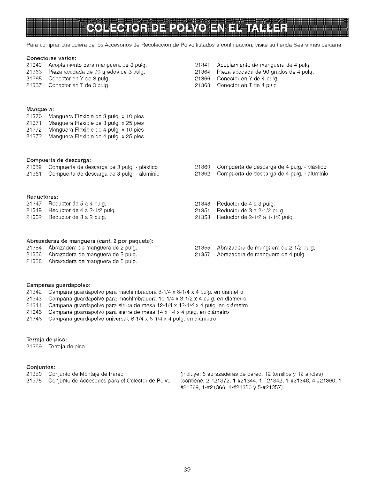
Para comprar cualquiera de los Accesorios de Recolecci6n de Polvo listados a continuaci6n, visite su tienda Sears mas cercana.
Conectores varios:
21340 AcopIamiento para manguera de 3 puIg. 21341
21363 Pieza acodada de 90 grades de 3 pulg. 21364
21365 Conector en Y de 3 puIg. 21366
21367 Conector en T de 3 puIg. 21368
Acoplamiento de manguera de 4 pulg.
Pieza acodada de 90 grados de 4 puIg.
Conector en Y de 4 puIg.
Conector en T de 4 pulg.
Manguera:
21370 Manguera Flexible de 3 pulg. x 10 pies
21371 Manguera Flexible de 3 pulg. x 25 pies
21372 Manguera Flexible de 4 pulg. x 10 pies
21373 Manguera Flexible de 4 pulg. x 25 pies
Compuerta de descarga:
21359 Compuerta de descarga de 3 pulg. - plastico
21361 Compuerta de descarga de 3 pulg. - aluminio
21360 Compuerta de descarga de 4 pulg. - plgstico
21362 Compuerta de descarga de 4 pulg. - aluminio
Reductores:
21347 Reductor de 5 a 4 puIg.
21349 Reductor de 4 a 2-1/2 puIg.
21352 Reductor de 3 a 2 puIg.
21348
21351
21353
Reductor de 4 a 3 pulg.
Reductor de 3 a 2-1/2 putg.
Reductor de 2-1/2 a 1-1/2 puIg.
Abrazaderas de manguera (cant. 2 per paquete):
21354 Abrazadera de manguera de 2 pulg.
21356 Abrazadera de manguera de 3 pulg.
21358 Abrazadera de manguera de 5 pulg.
21355
21357
Abrazadera de manguera de 2-1/2 pulg.
Abrazadera de manguera de 4 puIg.
Campanas guardapolvo:
21342 Campana guardapolvo para machimbradora 8-1/4 x 8-1/4 x 4 pulg. en diametro
21343 Campana guardapolvo para machimbradora 10-1/4 x 8-1/2 x 4 puIg. en diametro
21344 Campana guardapoIvo para sierra de mesa 12-1/4 x 12-1/4 x 4 puIg. en diametro
21345 Campana guardapolvo para sierra de mesa 14 x 14 x 4 pulg. en diametro
21346 Campana guardapolvo universal, 6-1/4 x 6-1/4 x 4 pulg. en diametro
Terraja de piso:
21369 Terraja de piso
Conjuntos:
21350 Conjunto de Montaie de Pared
21375 Conjunto de Accesorios para el Colector de Polvo
(incluye: 6 abrazaderas de pared, 12 tornillos y 12 anclas)
(contiene: 2-#21372, 1-#21344, 1-#21342, 1-#21346, 4-#21360, 1
#21369, 1-#21366, 1-#21350 y 5-#21357).
39
Apague el interruptor de energfa y desenchufe el cord6n de
potencia de su fuente de energfa antes de realizar cualquier
mantenimiento. Asegurese siempre de que Ias tapas de puer-
to de admisi6n cubran los puertos de admisi6n cuando una
manguera no se encuentre conectada al cobctor de polvo.
No permita que Ias astiiIas y el polvo se acumulen bajo el
coIector de polvo. Mantenga la zona limpia yen seguro
estado.
PRECAUC_ON: NO UT_UCE MATER_ALES 8NFLAMABLES
para limpiar el cobctor de polvo.
El Colector de Polvo tiene cojinetes lubricados seiIados en la
carcasa de motor. No se requiere ning0n lubricado adicionat
por parte del operario.
Con el Cobctor de Potvo desenchufado, purgue el motor con
aire a baja presi6n para eliminar polvo o sucbdad. No debe
hacerse uso de Ia presi6n de aire por encima de los 50 PSi,
ya que podr& daharse el aisiamiento. El operario debe utilizar
protecci6n ocular en todo momento durante el uso de aire
comprimido.
Las reparaciones al Colector de Polvo deben ser realizadas
por personal experto solamente. Comunfquese con su Centro
de Servicio Sears mas cercano para obtener servicio autori-
zado. Las reparaciones desautorizadas o el reemplazo con
piezas que no sean de fabrica podr9 resuttar en bsiones
graves al usuario y daho al cobctor de polvo.
PARA PREVENJR LAS LESIONES PERSONALES o el daSo al Coiector de Polvo, coloque ei interruptor en la posici6n de
"APAGADO" y desenchufe el cord6n de energfa del tomacorrientes antes de realizar cualquier ajuste.
PROBLEMA CAUSA PROBABLE SOLUCION
_,_otor no arranca
Motor caRado
(resamtando en
fasiMes fundidos
o disyuntores
disparados)
Motor arl'anoa con
meatitud o no amcanza
pbaa vemocidad
Motor marcha
demasiado camiente
Apertura frecuente de
fusiMes o disyuntores
de circuito
1. Interruptor no oprimido Io suficiente o
interruptor en el posici6n de "APAGADO"
2. Interruptor defectuoso
3. Capacitador defectuoso
4. Baja tensi6n de Ifnea
5. Motor defectuoso
2.
3.
2.
1.
2.
3.
1. Presione el interruptor hacia adentro 1/2 pulg. o
asegurese de que este an la posici6n de 'ENCENDiDO".
2. Haga sustituir e! interruptor.
3. Haga sustituir e! capacitador.
4. Corrija la condiei6n de baja tensi6n de linea
5. Reponga/repare el motor
AVISO: 2, 3 y 4 deben ser realizados por un tecnico
califieado; comuniquese con el servicio de Sears.
Sobrecarga del circuito 1.
Bajo voltaje de linea 2.
Impulsador atascado por asfillas o escombros 3.
Sobrecarga del motor 4,
Fusibles incorrectos en los disyuntores de 5.
circuito
Cortocircuitado el motor; conexiones sueltas 6.
o aislamiento gastado an los avances
Devanado defectuoso del motor. 1.
Capacitador defectuoso 2.
Restrieei6n de la eireulaei6n de aire debido a
la aeumulaci6n de polvo
Sobrecarga del motor
Fusibles o disyuntores earecen de eapacidad
suficiente
Circuito sobrecargado
Motor sobrecargado
Reduzca la carga de! circuito.
Corrija la condici6n de baja tensi6n de linea.
Limpie todas las mangueras, bolsas y la carcasa de astillas
y escombros.
Reduzca la carga de! motor.
Haga instalar los fusibles correctos en el disyuntor.
Inspeccione los terminabs del motor por si existe aislamiento
daflado y cables cortocircuitados; mande a sustituirlos.
Haga que repongan o reparen el motor.
Haga sustituir e! capacitador.
1A. Limpie e! polvo y restaure la circulaci6n normal del aire.
lB. Vacfe y limpie las bolsas de filtro y de recolecci6n.
2. Reduzca la carga de! motor.
1. Haga instalar los fusibles o disyuntores correctos.
2. Reduzca la carga de! circuito (apague los demAs enseres).
3. Reduzca la carga de! motor.
4O
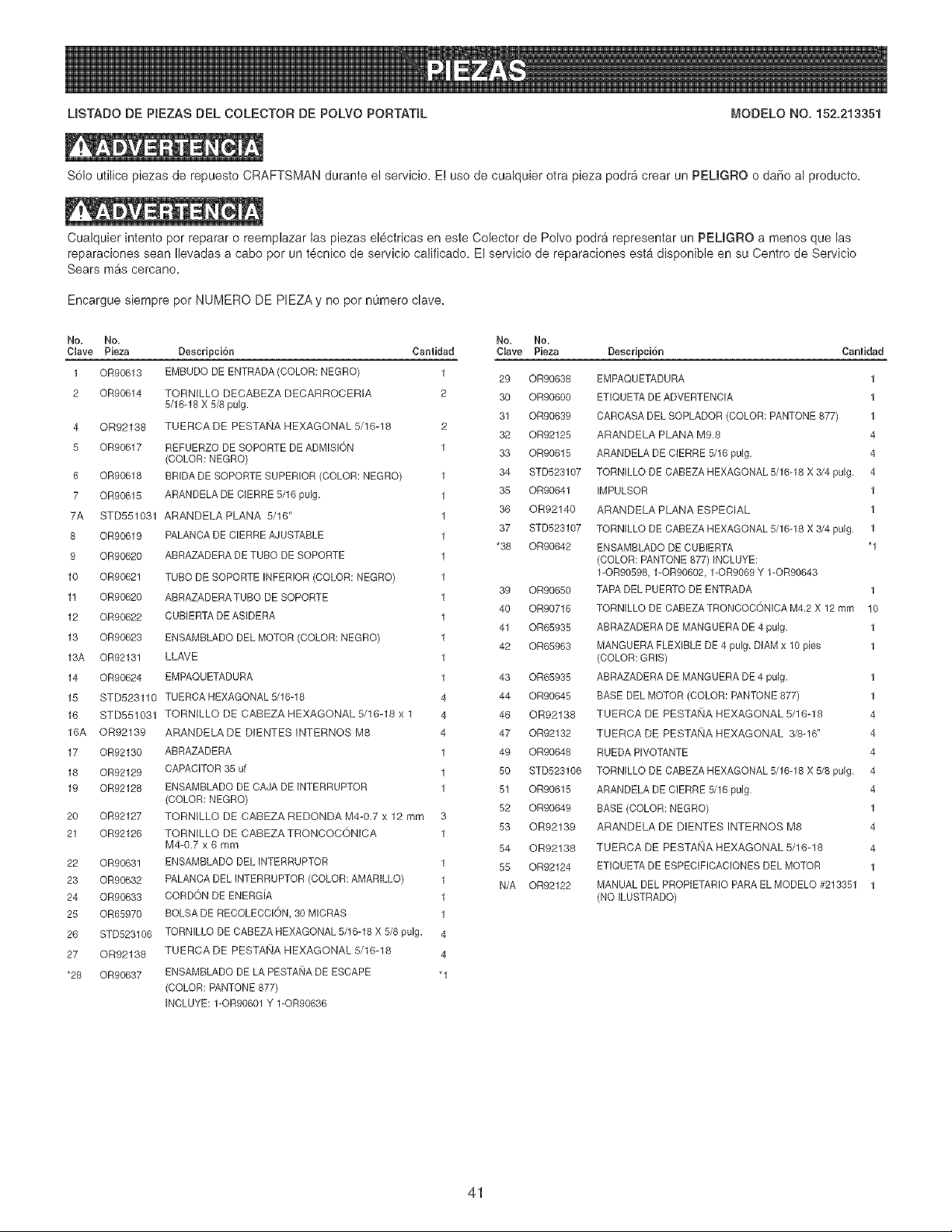
MSTADO DE PIEZAS DEL COLECTOR DE POLVO PORTATmL _,'IODELO NO. 152.213351
S61o utilice piezas de repuesto CRAFTSMAN durante e! servicio. E! use de cualquier otra pieza podr& crear un PEUGRO o daSo al producto.
Cualquier intento per reparar o reemplazar las piezas el@tricas en este Colector de PoIvo podra representar un PEMGRO a menos que las
reparaciones sean Ilevadas a cabo por un t@nico de servicio calificado, El servicio de reparaciones esta disponible en su Centre de Servicio
Sears mas cercano,
Encargue siempre pot NUMERO DE PIEZA y no pot numero clave.
No. No.
Clave Pieza Cantidad
1 OR90613 1
2 OR90614 2
4 OR92138
5 OR90617
6 OR90618
7 OR90615
7A STD551031
8 OR90619
9 OR90620
10 OR9062!
11 OR90620
12 OR90622
13 OR90623
13A OR9213!
14 OR90624
15 STD523110
16 STD551031
16A OR92139
17 OR92130
18 OR92129
19 OR92128
20 OR92127
21 OR92126
22 OR9063!
23 OR90632
24 OR90633
25 OR65970
26 STD523106
27 OR92138
*28 OR90637
Descripci6n
EMBUDO DE ENTRADA (COLOR: NEGRO)
TORNILLO DECABEZA DECARROCERIA
5/16-!8 X 5/8 pulg.
TU ERCA DE PESTANA HEXAGONAL 5/16-18
REFUERZO DE SOPORTE DE ADMISION
(COLOR: NEGRO)
BRIDA DE SOPORTE SUPERIOR (COLOR: NEGRO)
ARANDELA DE CERRE 5/16 pulg.
ARANDELA PLANA 5/16"
PALANCA DE C_ERREAJUSTABLE
ABRAZADERA DE TUBO DE SOPORTE
TUBO DE SOPORTE INFERIOR (COLOR: NEGRO)
ABRAZADERA TUBO DE SOPORTE
CUBIERTA DE AS_DERA
ENSAMBLADO DEL MOTOR (COLOR: NEGRO)
LLAME
EMPAQUETADURA
TUERCA HEXAGONAL 5/16-18
TORNILLO DE CABEZA HEXAGONAL 5/16-18 x 1
ARANDELA DE DIENTES INTERNOS M8
ABRAZADERA
CAPACITOR 35 uf
ENSAMBLADO DE CAJA DE INTERRUPTOR
(COLOR: NEGRO)
TORNILLO DE CABEZA REDONDA M4-0.7 x 12 rnm
TORNILLO DE CABEZA TRONCOCONICA
M4-0.7 x 6 mm
ENSAMBLADO DEL _NTERRUPTOR
PALANCA DEL INTERRUPTOR (COLOR: AMARILLO)
CORDON DE ENERGiA
BOLSA DE RECOLECCION, 30 M_CRAS
TORNILLO DE CABEZA HEXAGONAL 5/16-18 X 5/8 pulg.
TU ERCA DE PESTANA HEXAGONAL 5/16-18
ENSAMBLADO DE LA PESTA_,_ADE ESCAPE
(COLOR: PANTONE 877)
_NCLUYE: 1-OR90601 Y 1-OR90636
4
4
4
1
1
1
4
4
"1
No. No.
Clave Pieza
29 OR90638
30 OR90600
31 OR90639
32 OR92125
33 OR906!5
34 STD523107
35 OR90841
36 OR92140
37 STD523107
*38 OR90642
39 OR90650
Descripci6n Cantidad
EMPAQUETADURA 1
ETIOUETA DE ADVERTENCIA 1
OARCASA DEL SOPLADOR (COLOR: PANTONE 877) 1
ARANDELA PLANA M9,8 4
ARANDELA DE CIERRE 5/16 pulg, 4
TORN_LLO DE CABEZA HEXAGONAL 5/16-18 X 3/4 pulg, 4
IMPULSOR 1
ARANDELA PLANA ESPECIAL 1
TORN_LLO DE CABEZA HEXAGONAL 5/16-18 X 3/4 pulg, 1
ENSAMBLADO DE CUBIERTA "1
(COLOR: PANTONE 877) INCLUYE:
1-OR90598, 1-OR90602, 1-OR9069 Y 1-OR90643
TAP.&DEL PUERTO DE ENTRADA 1
40
41
42
43
44
46
47
49
5O
51
52
53
54
55
N/A
OR90716
OR65935
OR65963
OR65935
OR90645
OR92138
OR92132
OR90648
STD523106
OR90615
OR90649
OR92139
OR92138
OR92124
OR92122
TORN_LLO DE CABEZATRONCOCONICA M4.2 X 12 mrn 10
ABRAZADERA DE MANGUERA DE 4 pulg, 1
MANGUERA FLEXIBLE DE 4 pulg. DIAM x 10 pies 1
(COLOR: GRIS)
ABRAZADERA DE MANGUERA DE 4 pulg. 1
BASE DEL MOTOR (COLOR: PANTONE 877) 1
TUERCA DE PESTANA HEXAGONAL 5/16-18 4
TUERCA DE PESTANA HEXAGONAL 3/8-16" 4
RUEDA PIVOTANTE 4
TORN_LLO DE CABEZA HEXAGONAL 5/16-18 X 5/8 pulg, 4
ARANDELA DE CIERRE 5/16 pulg, 4
BASE (COLOR: NEGRO) 1
ARANDELA DE DIENTES INTERNOS M8 4
TUERCA DE PESTANA HEXAGONAL 5/16-18 4
ETIQUETA DE ESPECIFICACIONES DEL MOTOR 1
MANUAL DEL PROP_ETARIO PARA EL MODELO #213351 1
(NO ILUSTRADO)
41

USTADO DE PIEZAS DEL COLECTOR DE POLVO PORTATmL MODELO NO. 152.213351
57
%
42

NOTAS
43

Your Home
For repair - in your home - of aH major brand appliances,
iiiiiiiiiiiiiiiiiiiii_
.... lawn and garden equipment, or heating and cooling systems,
oomo_te_whomo_ei_,oomo_te_who_omdi. ....................
For the replacement parts, accessories and
owner's manuals that you need to do-it-yourself.
For Sears professional installation of home appliances
and items like garage door openers and water heaters.
iiiiiiiiiiiiiiHHH
1-800-4-MY-HOME ® Anytime, day or night
(1-800-469-4663) (U.S.A. and Canada)
www_eo,_oo_ www_eo,_oo
HHHHHHHHHH
o ur Home
For repair of carry-in products like vacuums, lawn equipment,
and electronics, call or go on-line for the location of the nearest ....................
Sears Parts & .epair Center.
1-800-488-1222 Anytime, day or night (U.S.A. only)
TopurchaseaprotectionagreementtU.S.A./
or maintenance agreement (Canada)or, a product serviced by Sears:
1-800o827-6655 (U.S.A.) 1-800-361-6665 (Canada)
Au Canada pour service en francais:
'" Para pedir servicio de reparaci6n a
domicilio, y para ordenar piezas: 1-800-LE-FOYER MC
(1°800°533°6937)
......1-888 -SU-HOG A F{sM
....................... (1o888o784o8427)
®) Sears, Roebuck and Co.
® Registered Trademark / TMTrademark / sMService Mark of Sears, Roebuck and Co.
® Marca Registrada / TMMarca de Fgbrica / _;MMama de Servicio de Sears, Roebuck and Co.
MC Marque de commerce / MDMarque d_pos_e de Sears, Roebuck and Co. ¢3 Sears, Roebuck and Co.