Loading ...
Loading ...
Loading ...
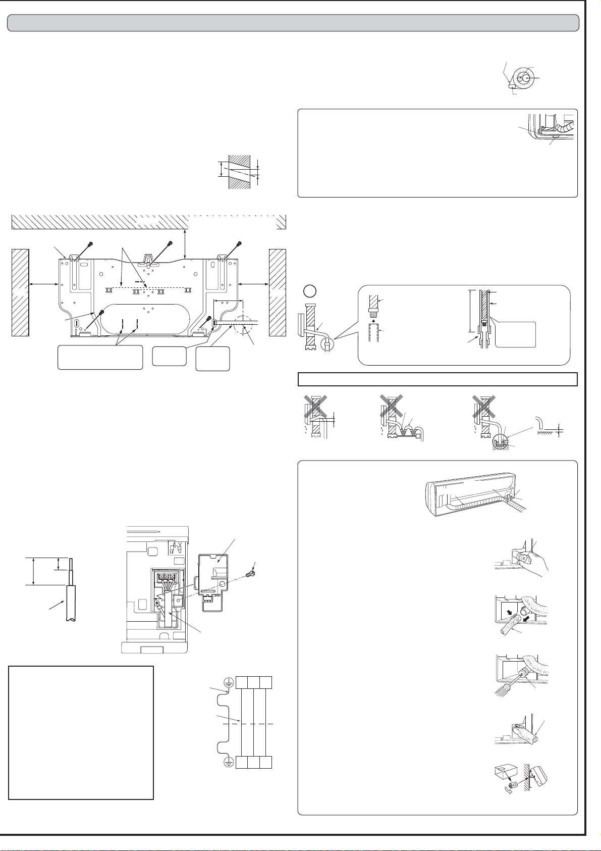
2-1. FIXING OF INSTALLATION PLATE
)LQGDVWUXFWXUDOPDWHULDOVXFKDVDVWXGLQWKHZDOODQG¿[LQVWDOODWLRQSODWHKRUL]RQ-
WDOO\E\WLJKWHQLQJWKH¿[LQJVFUHZV¿UPO\
7RSUHYHQWLQVWDOODWLRQSODWHIURPYLEUDWLQJEHVXUHWRLQVWDOOWKH¿[LQJVFUHZVLQWKH
KROHVLQGLFDWHGLQWKHLOOXVWUDWLRQ)RUDGGHGVXSSRUW¿[LQJVFUHZVPD\DOVREHLQVWDOOHG
in other holes.
:KHQWKHNQRFNRXWLVUHPRYHGDSSO\YLQ\OWDSHWRWKHNQRFNRXWHGJHVWRSUHYHQWGDPDJ-
ing the wires.
:KHQEROWVUHFHVVHGLQWKHFRQFUHWHZDOODUHWREHXWLOL]HGVHFXUHLQVWDOODWLRQSODWH
using 11 × 20 · 11 × 26 oval hole (450 mm pitch).
,IWKHUHFHVVHGEROWLVWRRORQJFKDQJHLWIRUDVKRUWHURQHDYDLODEOHLQWKHPDUNHW
2-2. WALL HOLE DRILLING
'HWHUPLQHWKHZDOOKROHSRVLWLRQ
'ULOO D¡ PP KROH 7KH RXWGRRUVLGH VKRXOG EH WR
7 mm lower than the indoor side.
3) Insert wall hole sleeve (C).
2-3. CONNECTING WIRES FOR INDOOR UNIT
You can connect indoor/outdoor lead wire without removing the front panel.
1) Open the front panel.
2) Remove VA clamp.
3) Pass indoor/outdoor unit connecting wire (A) from the back of the indoor unit and process
the end of the wire.
/RRVHQWHUPLQDOVFUHZDQGFRQQHFW¿UVWWKHHDUWKZLUHWKHQLQGRRURXWGRRUXQLWFRQ-
QHFWLQJZLUH$WRWKHWHUPLQDOEORFN%HFDUHIXOQRWWRPDNHPLVZLULQJ)L[WKHZLUHWR
the terminal block securely so that no part of its core is appeared, and no external force
is conveyed to the connecting section of the terminal block.
5) Firmly tighten the terminal screws to prevent them from loosening. After tightening, pull
WKHZLUHVOLJKWO\WRFRQ¿UPWKDWWKH\GRQRWPRYH
6) Secure indoor/outdoor unit connecting wire (A) and the earth wire with the VA clamp.
Never fail to hook the left claw of the VA clamp. Attach the VA clamp securely.
2-4. PIPE FORMING AND DRAIN PIPING
Pipe Forming
3ODFHWKHGUDLQKRVHEHORZWKHUHIULJHUDQWSLSLQJ
0DNHVXUHWKDWWKHGUDLQKRVHLVQRWKHDYHGRUVQDNHG
'RQRWSXOOWKHKRVHZKHQDSSO\LQJWKHWDSH
:KHQWKHGUDLQKRVHSDVVHVWKHURRPEHVXUHWRZUDSLQVXOD-
tion material (obtainable at a store) around it.
2. INDOOR UNIT INSTALLATION
Rear, right, or downward piping
1) Put the refrigerant piping and the drain hose togeth-
HUWKHQ¿UPO\DSSO\SLSLQJWDSH*IURPWKHHQG
2) Insert the piping and the drain hose into the wall
hole sleeve (C), and hook the upper part of the
indoor unit on the installation plate (1).
3) Check if the indoor unit is hooked securely on the installation plate (1) by moving the
unit to left and right.
4) Thrust the lower part of the indoor unit into the installation plate (1).
Drain Piping
,IWKHH[WHQVLRQGUDLQKRVHKDVWRSDVVWKURXJKDURRPEHVXUHWRZUDSLWZLWKFRPPHU-
cially sold insulation.
7KHGUDLQKRVHVKRXOGSRLQWGRZQZDUGIRUHDV\GUDLQÀRZ)LJ
,IWKHGUDLQKRVHSURYLGHGZLWKWKHLQGRRUXQLWLVWRRVKRUWFRQQHFWLWZLWKGUDLQKRVH,
that should be provided at your site. (Fig. 2)
:KHQFRQQHFWLQJWKHGUDLQKRVHWRWKHKDUGYLQ\OFKORULGHSLSHEHVXUHWRLQVHUWLWVHFXUHO\
into the pipe. (Fig. 3)
'RQRWPDNHGUDLQSLSLQJDVVKRZQEHORZ
'RQRWUDLVH
Accumulated
drain water
Air
Waving
Water
leakage
Water
leakage
Water
leakage
Tip of drain
hose dipped
in water
'LWFK
At least
50 mm
gap
'RZQZDUG
slope
'UDLQ
hose
Soft hose
,'PP
'UDLQKRVH
Hard vinyl chloride
SLSH,'PP
Insert
securely
'LIIHUHQW
diameter joint
70 cm
or more
Fig. 1 Fig. 2 Fig. 3
)RU IXWXUH VHUYLFLQJ JLYH H[WUDOHQJWK WR
the connecting wires.
0DNHHDUWKZLUHDOLWWOHORQJHUWKDQRWKHUV
(More than 60 mm)
'RQRWIROGWKHH[FHVVZLUHRUFUDPLWLQWR
small space. Take caution not to damage
the wires.
%HVXUHWRDWWDFKHDFKVFUHZWRLWVFRUUH-
spondent terminal when securing the cord
and/or the wire to the terminal block.
Note:'RQRWSODFHWKHZLUHVEHWZHHQWKH
indoor unit and the installation plate (1).
'DPDJHGZLUHFRXOGFDXVHKHDWJHQHUD-
WLRQRU¿UH
Wall
Outdoor
side
ø65 mm
5-7 mm
Installation plate (1)
Center of
ø65 mm hole
126 mm
or more
106 mm
or more
61 mm or more
138 mm or more for left and left
back piping (using spacer)
Ceiling
Wall
Wall
Fixing
screw (2)
100 mm
Level
* Same for left hole.
Fixing screw
VA clamp
Indoor/outdoor unit
connecting wire (A)
Lead wire
15 mm
35 mm
Indoor terminal block
Indoor/outdoor
unit connecting
wire (A)
Outdoor terminal block
Earth wire
(green/yellow)
S1 S2 S3
S1 S2 S3
Felt tape (4)
Piping tape (G)
Cut off in case of
left piping.
'UDLQFDS
'UDLQFDS
'UDLQKRVH
'UDLQFDS
'UDLQKRVH
Fig. 1
Fig. 2
Fig. 3
Fig. 4
Fig. 5
1) Put the refrigerant piping and the drain hose together,
WKHQ¿UPO\DSSO\IHOWWDSHIURPWKHHQG
Felt tape (4) overlap width should be 1/3 the tape width.
Use a bandage stopper at the end of felt tape (4).
2) Pull out the drain cap at the rear right of the indoor unit.
(Fig. 1)
+ROGWKHFRQYH[VHFWLRQDWWKHHQGDQGSXOOWKHGUDLQ
cap.
3) Pull out the drain hose at the rear left of the indoor unit.
(Fig. 2)
+ROGWKHFODZPDUNHGE\WKHDUURZVDQGSXOORXWWKH
drain hose forward.
4) Put the drain cap into the section to which the drain hose
is to be attached at the rear of the indoor unit. (Fig. 3)
,QVHUWQRWVKDUSHGJHGWRROVVXFKDVVFUHZGULYHUVLQWR
the hole at the end of the cap and insert the cap fully
into the drain pan.
5) Insert the drain hose fully into the drain pan at the rear
right of the indoor unit. (Fig. 4)
&KHFNLIWKHKRVHLVKRRNHGVHFXUHO\WRWKHSURMHFWLRQ
of its inserting part at the drain pan.
6) Insert the drain hose into wall hole sleeve (C), and hook
the upper part of indoor unit on installation plate (1).
Then, move the indoor unit completely to the left in order
to make placing the piping in the back space of the unit
easier.
7) Cut out a piece of cardboard from the shipping box, roll
it up, hook it onto the back rib, and use it as a spacer to
lift the indoor unit. (Fig. 5)
8) Connect the refrigerant piping with the extension pipe
%
9) Thrust the lower part of the indoor unit into the installation
plate (1).
Left or left-rear piping
Note:
%H VXUH WR UHDWWDFK WKH GUDLQ KRVH
and the drain cap in case of left or
left-rear piping.
Otherwise, it could cause drops of
water to drip down from the drain
hose.
Liquid pipe
Gas pipe
Felt tape (4)
Indoor/outdoor unit
connecting wire (A)
Piping tape (G)
Insert the
scale. *
The union joints of the indoor
unit are 110 mm to the left of
these punch marks.
Align the
scale with
the line. *
Cut off in case of
right piping.
Cut off in case of
downward piping.
Loading ...
Loading ...
Loading ...