
7
ASSEMBLY
IMPORTANT: This mower is shipped without gasoline or oil in
the engine. Be certain to service engine with gasoline and oil as
instructed in the Operation section of the Engine Manual before
starting or operating your mower.
NOTE: Reference to right and left hand side of the Lawn Mower is
observed from the operating position.
Unpacking
OPENING CARTON
1. Cut each corner of the carton vertically from top to bottom.
2. Remove all loose parts:
• Grass Catcher (if equipped)
• Engine Oil
3. Remove loose packing material.
REMOVING MOWER FROM CARTON
1. Lift mower from the rear to detach it from underlying carton
material and roll mower out of carton.
2. Check carton thoroughly for any other loose parts.
3. Remove any packing material which may be between upper
and lower handles.
Mower Assembly
Preform the following procedures to assemble and set up the
mower:
• Handle Assembly
• Pull-Out Handle. See page 7.
• Folding Handle. See page 8.
• Vertical Storage Handle. See page 9.
• Recoil Starter Rope Handle Assembly
• Attaching the Grass Catcher (if equipped)
• Attaching Side Discharge Chute or Side Discharge Blower
(if equipped)
• Electric Start Set-Up (If Equipped)
NOTE: If necessary, refer to the procedures in the Adjustments
Section after assembling the mower.
Handle Assembly
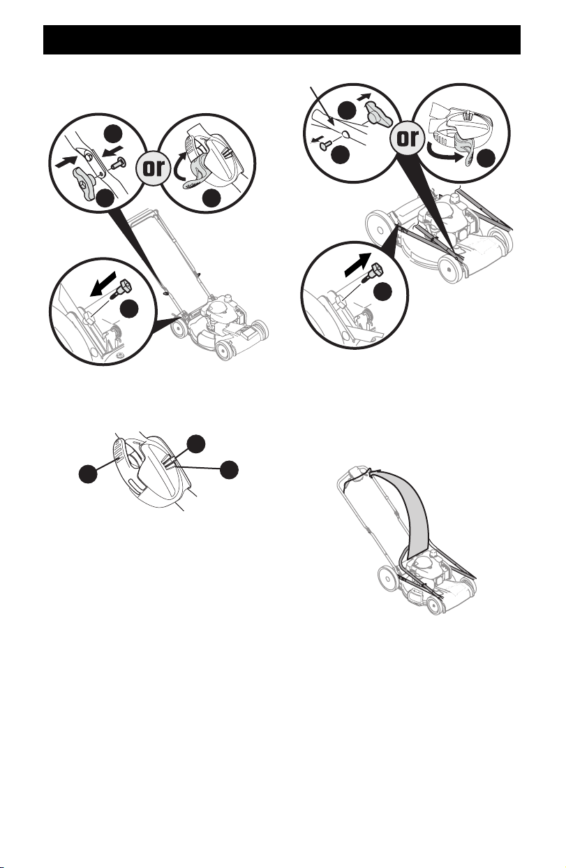
PULLOUT HANDLE
1. Remove knobs or wing nuts (a) and carriage bolts (b) from
the handle or if equipped with the EZ-lock handle (c), proceed
to STEP 2 (Figure 1).
NOTE: The EZ-Fold handle release levers are shipped in the
unlocked position.
Do not loosen
or remove hex
head screws.
a
c
b
Figure 1
2. Remove T-bolts (d) from the handle brackets (Figure 2).
3. While stabilizing mower so it doesn’t move, pivot upper
handle (e) up (Figure 2). Do not crimp blade or drive control
cables while lifting the handle up.
e
d
Figure 2
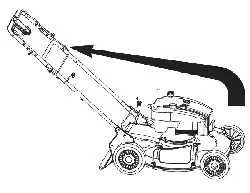
4. Pull upward on the handle (e) (Figure 3) until holes in lower
handle (f) line up with holes in handle brackets (g) (Figure 3
Inset, Deck Cutaway).
NOTE: When pulling upward on handle, do not pull handle all
the way out of the handle brackets.
e
g
f
Figure 3
8
ASSEMBLY
5. Reattach knobs or wing nuts (a) and carriage bolts (b)
removed in STEP 2 into lower holes of the handle or lock the
EZ-fold handle release levers (c) (Figure 4).
d
a c
b
Figure 4
IMPORTANT: When locking the EZ-fold handle release lever (c)
ensure the position indicator (h) aligns with one of three handle
positions (i) (Figure 5).
h
i
c
Figure 5
6. Insert the T-bolts (d) removed in STEP 4 through the handle
brackets and lower handle (Figure 4) and tighten securely to
secure the handle in place.
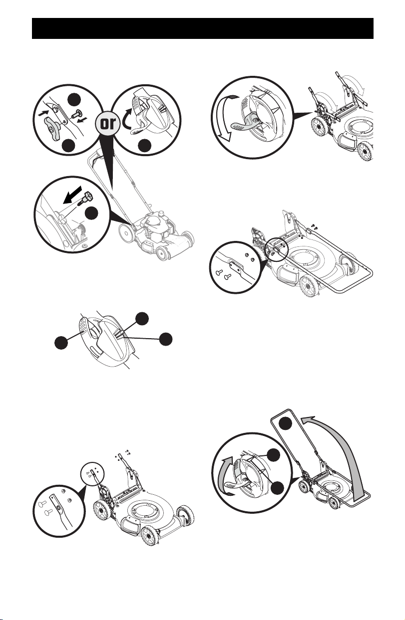
FOLDING HANDLE
1. Remove knobs or wing nuts (a) and carriage bolts (b) from
the handle or if equipped with the EZ-lock handle (c), proceed
to STEP 2 (Figure 6).
NOTE: The EZ-Fold handle release levers are shipped in the
unlocked position.
Do not loosen or remove hex head screws.
a
c
b
d
Figure 6
2. Remove the T-bolts (d) from the handle brackets (Figure 6).
3. While stabilizing mower so it doesn’t move, gently lift and
pivot the upper handle into the operating position (Figure
7). Make certain the lower handle is seated securely into the
handle brackets. Do not crimp blade or drive control cables
while lifting the handle up
Figure 7
9
ASSEMBLY
4. Reattach knobs or wing nuts (a) and carriage bolts (b)
removed in STEP 2 into lower holes of the handle or lock the
EZ-fold handle release levers (c) (Figure 8).
d
a c
b
Figure 8
IMPORTANT: When locking the EZ-fold handle release lever (c)
ensure the position indicator (e) aligns with one of three handle
positions (f) (Figure 9).
c
e
f
Figure 9
5. Using the T-bolts (d) removed in STEP 2, secure the lower
handle to the handle brackets (Figure 8) and tighten securely
to secure the handle in place.
VERTICAL STORAGE HANDLE
1. Remove the four carriage bolts and nuts from the lower
handles (Figure 10).
Figure 10
2. Unlock the two handle release levers. See inset, Figure 11.
3. Ensure the lower handles are folded forward towards the
front of the mower.
Figure 11
4. Using the four carriage bolts and nuts removed in STEP
2, secure the upper handle to the lower handle. Tighten
hardware securely to secure the handle in place (Figure 12).
Figure 12
5. While stabilizing mower so it doesn’t move, lift the upper
handle up (a) (Figure 13). Do not crimp blade or drive control
cables while lifting the handle up.
6. When lifting the upper handle ensure the position indicator
(b) aligns with one of three handle positions (c). See inset,
Figure 13.
7. Lock the two handle release levers. See inset, Figure 13.
8. Ensure all hardware is securely tightened.
a
c
b
Figure 13
10
ASSEMBLY
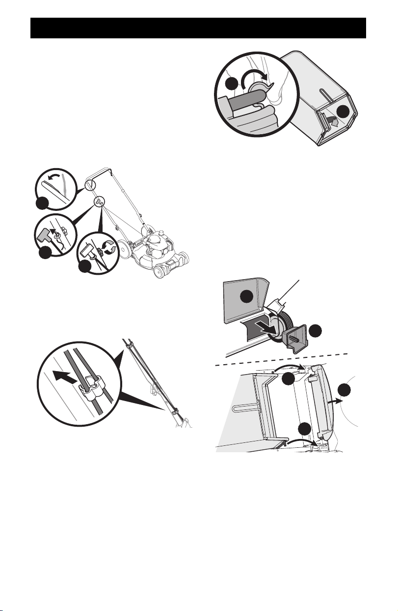
Recoil Starter Rope Handle Assembly
NOTE: The rope guide is attached to the right side of the upper
handle. Loosen the knob securing the rope guide (Figure 14).
NOTE: Vertical Storage Mowers Only: The recoil starter rope is
equipped with a rope stop clamp to prevent the starter rope
being pulled into the engine. Do not remove the rope stop clamp.
1. Hold blade control against upper handle.
2. Slowly pull recoil starter rope handle from engine and slip
starter rope into the rope guide.
3. Tighten rope guide knob.
1
2
3
Figure 14
NOTE: On select units, use the two cable clips provided to secure
blade control and drive cables to lower handle (Figure 15).
IMPORTANT: To reduce wear and allow for proper operation,
make sure to leave some slack in the upper portion of the cables.
Figure 15
Attaching the Grass Catcher (If Equipped)
1. Perform the following to assemble the grass catcher
(Figure 16).
NOTE: Before assembling the grass catcher, ensure the grass
bag is turned right side out, with the warning label showing
on the outside.
a. Place bag over frame so that its black plastic side is at the
bottom.
b. Slip plastic channels (a) of grass bag over the frame (b).
a
b
Figure 16
2. Follow steps below to attach grass catcher (Figure 17):
a. Lift rear discharge door (a).
b. Remove the rear mulch plug (b) (if equipped).
c. Place grass catcher into the slots in the handle brackets
(c). Lower the discharge door so that it rests on the grass
catcher.
NOTE: To remove grass catcher, lift rear discharge door on the
mower. Lift grass catcher up and off the slots in the handle
brackets. Reinstall the rear mulch plug (if equipped). Release
rear discharge door to allow it to close rear opening of mower.
b
a
c
c
a
Figure 17
11
ASSEMBLY
Attaching Side Discharge Chute or Side
Discharge Blower (If Equipped)
The mower is shipped as a mulcher. To convert to side discharge
or side discharge blower, ensure the grass catcher is removed,
the rear mulch plug is installed (if equipped) and the rear
discharge door is closed.
1. Lift the mulch plug (Figure 18).
2. Slide the two hooks of the side discharge chute (a) or side
discharge blower (b) under the mulch plug hinge pin. Lower
the mulch plug.
IMPORTANT: Do not remove side mulch plug at any time.
a
b
1 1
2 2
Figure 18
NOTE: Some side discharge chutes include a clip to secure the
discharge chute to the handle. If equipped, the side discharge
chute can be secured to the handle when not in use (Figure 19).
Figure 19
Electric Start Set-Up (If Equipped)
NOTE: Mowers equipped with electric start will use either a
lead acid battery in an enclosed battery box (see Electric Starter
Battery Box) or a removable lithium ion battery pack (See
Installing/Removing Battery Pack).
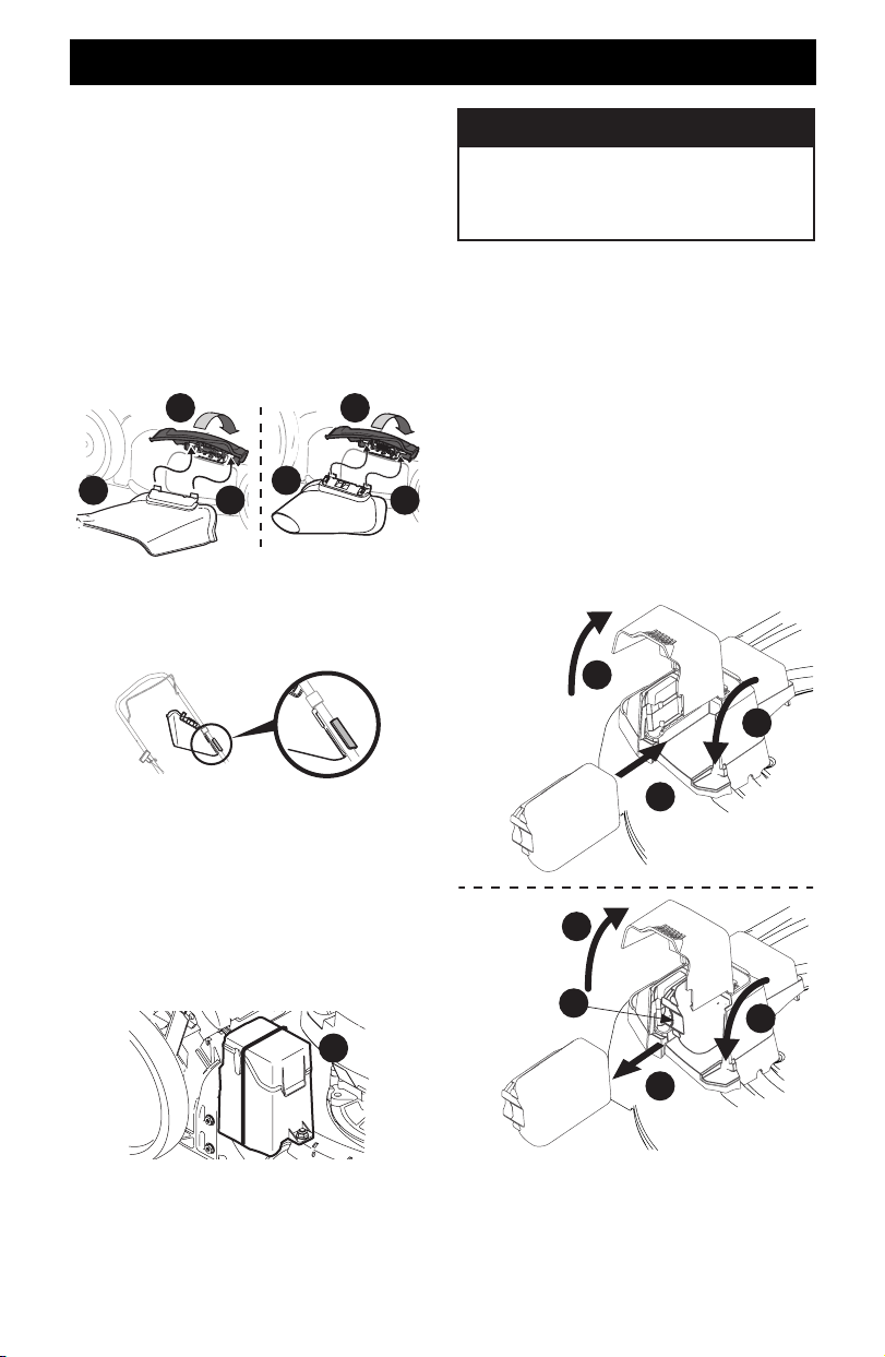
ELECTRIC STARTER BATTERY BOX IF EQUIPPED
NOTE: Remove cable tie (a) from around battery box. Cable tie is
used for shipping only (Figure 20).
a
Figure 20
INSTALLING/REMOVING BATTERY PACK IF EQUIPPED
NOTE: To ensure maximum performance and life of lithium-ion
battery packs, charge the battery fully before first use.
WARNING
Read all safety warnings, instructions, and cautionary
markings for the battery pack, charger and product.
Failure to follow the warnings and instructions may
result in electric shock, fire and/or serious injury.
IMPORTANT: Refer to instructional manual supplied with
battery charger for charging, maintenance and battery disposal
instructions.
Installing The Battery Pack (Figure 21):
1. Lift the battery box cover.
2. Insert the battery pack into the battery box. An audible
“click” will be heard when the battery is properly connected.
3. Close the battery box cover.
Removing The Battery Pack (Figure 21):
1. Lift the battery box cover.
2. Press the battery pack release button.
3. Pull the battery pack from the battery box.
4. Close the battery box cover.
4
1
3
2
1
3
2
Installing
Battery Pack
Removing
Battery Pack
Figure 21