User Gudie Summit SGWOGD30 Wall Oven
OPERATING THE GAS OVEN
OVEN GAS BURNER IGNITION, REGULATION AND THERMOSTAT
- Open oven door completely (when igniting oven, if door is not open, oven cavity will fill with gas), then push and turn the thermostat knob counter-clockwise to the MAX setting. See figs. 01 and 02 at the back of this manual.
- A clicking sound will be heard and the burner will light. Look through orifice “F” for burner ignition. Keep pushing knob to allow thermocouple of the safety device to warm up enough, for about a period of 5 seconds. Then release the knob and turn it to the desired temperature setting
Attention:
- During first use of the oven gas burner, or after a long non-working period, the burner may not ignite at once, so try the ignition procedure again until the flow of gas allows ignition. If the problem persists, call an authorized technician for repair.
- In case of gas burner low setting regulation from Natural to LP gas, first convert the gas regulator to the desired gas type, following the instructions on pages 13 - 14. Preheat the gas burner to be converted for at least 5 minutes. Follow instructions in paragraph Low
- Setting Valve Adjustment on page 14.
GAS BROILER BURNER USE
- Set thermostat to Broil mode by turning knob clockwise. See fig. 03 at the back of this manual. Follow oven gas burner ignition procedure paragraph.
- Once broil burner is on, allow a period of time for preheating the oven cavity before broiling food.
Attention:
- Use the Grill with the oven door open and for a maximum time of 15 minutes.
Burner Operational Notes
- A properly adjusted burner with clean ports will light within a few seconds. If using natural gas the flame will be blue with a deeper blue inner cone.
- If the burner flame is yellow or is noisy, the air/gas mixture maybe incorrect. Contact a service technician to adjust.
- With LP gas, some yellow tips on the flames are acceptable. This is normal and adjustment is not necessary.
- If the control knob is turned very quickly from HIGH to LOW, the flame may go out, particularly if the burner is cold (oven burner). If this occurs, turn the knob to the OFF position, wait several seconds and relight the burner. Refer to LOW SETTING VALVE
- ADJUSTMENT chapter to adjust LOW setting, if needed.
ELECTRONIC TIMER
- When first powering on or in case of any electrical power failure and power has been restored, the electronic timer will start flashing. See Fig. 06.
TO SET TIME OF DAY
- Press button. Set time of day with “+” and “-” buttons.
- This function remains activated 7 seconds after the last “+” / “-” operation.
TO CHANGE TIME OF DAY
- Press the button for 4 seconds until the hours display flashes.
- Change the hours only by using the “+” or “-” button. The minutes and hidden seconds will not be affected.
TO SET TIMER FUNCTION
- This function will be activated with “+” button. Press “+” button again to increase duration time. During setting the count units are in 10 seconds steps or minutes.
- During countdown, the timer has priority on the display. The bell symbol is illuminated. The units are in seconds, or minutes for longer time periods.
- The maximum time is 10h. The format change will happen after 99 minutes and 59 seconds to 1 hour and 40 minutes.
- To show time of day, press the button. After 6 seconds, the countdown comes back on.
TO RESET TIMER
- Count down to zero by holding down the “-” button (automatic stop at zero).
SIGNAL
- The signal after “time out” will stay 7 minutes if it has not been reset with button.
- The following signal will be skipped if time of day is pressed during the last 15 seconds of the timer.
SIGNAL FREQUENCY
- If no function is activated, the signal frequency can be selected by pressing the “-“ button.
- Three different frequencies are selectable.
SELECTOR SWITCH
- This control allows you to turn on the Oven Internal Light or Oven Forced Air Convection
- Fan for cooking or defrosting purposes. See fig. 05.
OVEN LIGHT:
- Use this setting to turn on oven light. Light also remains on in all other modes.
FORCED AIR CONVECTION FAN OR DEFROST:
- Use this setting when forced air convection is necessary for a more even cooking finish. Also, use this setting to defrost frozen food by speeding up air circulation.
CAUTION:
- Do not store or use gasoline or other flammable vapors, liquids or items in the vicinity of this or any other appliance.
- Never use appliance as a space heater to heat or warm a room.
- Do not obstruct the flow of combustion and ventilation air by blocking the room vents or air intakes. Restriction of air flow to the gas appliance prevents proper performance and increases carbon monoxide emission to unsafe levels.
- Continuous use of the appliance may require extra ventilation. This can be accomplished by opening a window or increasing exhaust power of a cooking hood.
- If flame should go out during operation, turn the burner off. If a strong gas order is detected, open a window and wait five minutes before relighting the burner.
- Be sure all control knobs are set in the OFF position prior to supplying gas to the oven.
MAINTENANCE
CLEANING SAFETY
- Turn off all controls and wait for appliance parts to cool before touching or cleaning them.
- Do not touch the burners, oven inner surface or surrounding areas until they have had sufficient time to cool.
- Clean appliance with caution. Use care to avoid steam burns if a wet sponge or cloth is used to wipe spills on a hot surface. Some cleaners can produce noxious fumes if applied to a hot surface.
SURFACE AND OVEN COOKING CAVITY CLEANING
- This is easily done using a damp cloth and a non-abrasive detergent. Wipe using a soft dry cloth. For stainless steel parts with stubborn stains, use only a plastic scrubbing pad or sponge with vinegar and warm water.
- Because of the many new cleaning products introduced in the marketplace each year, it is not possible to list all products that can be safely used to clean this appliance.
- Read carefully the cleaner manufacturer’s instructions to be sure the cleaner can be safely used on this appliance.
- To determine if a cleaning product is safe, test a small inconspicuous area using a very light pressure to see if the surface is scratched or discolored. This is particularly important for porcelain, enamel, and highly polished, shiny, painted or plastic surfaces.
ABNORMAL OPERATION
- Any of the following are considered to be abnormal and may require servicing:
- Burner flame with yellow tips
- Difficult burner ignition
- Burners fail to remain lighted
- Burner flames out
- Difficulty turning gas valves.
OVEN DOOR
To remove oven door
- Fully open the oven door.
- Insert a metal Locking Pin (B) in the Locking Hole (A) on each of the hinges. (Fig. 07)
- Grasp the door by the sides toward the back. Raise the front of the door a few inches and make sure the Locking Pin (B) is locked by the door hinge. This will prevent the hinge from snapping closed when the door is removed. (There will be some spring resistance to overcome because of the hinge being locked). When the front of the door is high enough and hinges are locked, you will be able to lift the hinges to clear the slots.
- Pull the hinges out of the slots in the oven front frame.
To replace the oven door
- Grasp the sides of the door at the center. Insert the ends of the hinges and fix hinge slots in the oven front frame.
- With the door open all the way, pull out the two Locking Pins (B) from the hinge
Locking Holes (A).
- Raise the oven door and make sure it fits evenly with the front sides.
WARNING:
- Never take out the Locking Pins while the door is off. Do not close the hinges without the weight of the door. The powerful springs will snap the hinges closed with great force.
CAUTION: D
- o not place excessive weight or stand on an open oven door. This could cause the range to tip over, break the door, or injure the user. Also, do not attempt to open or close door or operate oven until door is properly replaced.
REPLACING THE OVEN LIGHT
- To prevent electrical shock and or personal injury:
- Before replacing the light bulb, be sure the electric power is turned off at the circuit breaker.
- Do not operate the oven unless the light cover is securely in position.
- Be sure the oven and light bulb are cool.
- Do not touch hot bulb with a damp cloth as this may cause the bulb to break.
- If the light cover is damaged or broken, do not use the oven until a new cover is in place.
To replace oven light bulb:
- Before replacing light bulb, disconnect oven electric circuit.
- Remove oven racks.
- Remove by unscrewing lens bulb cover and light bulb.
- Replace bulb with a 25 W – 120 VAC appliance bulb only.
- Replace lens bulb cover.
- Reconnect power to range. Reset electronic clock.
INSTALLATION INSTRUCTION
SPECIAL WARNING:
- ONLY QUALIFIED AND AUTHORIZED PERSONNEL SHALL INSTALL OR SERVICE
- THIS RANGE.
- READ “SAFETY INSTRUCTIONS” IN THIS BOOKLET BEFORE USING RANGE.
- IMPROPER INSTALLATION, ADJUSTMENT, ALTERATION, SERVICE,
- MAINTENANCE OR USE OF RANGE CAN RESULT IN SERIOUS INJURY OR
- PROPERTY DAMAGE, AND SO THE MANUFACTURE WILL NOT BE RESPONSIBLE.
- This appliance must be installed in accordance with the manufacturer’s installation instructions and local codes or, in the absence of local codes, with the National Fuel Gas
- Code, ANSI Z223.1 / NFPA 54 in the U.S.A., and current CAN/CSA B149.1 Natural Gas and Propane Installation Code.
CLEARANCE DIMENSIONS
- Appliance may be installed with zero inches clearance adjacent to (against) combustible construction at the rear and on the sides.
- For complete information in regard to the installation of wall cabinets around the oven and clearances to combustible walls, see the installation drawing fig. n° 08.
- For Safety Considerations, do not install unit in any combustible cabinetry which is not in accordance with the installation drawings.
- The recess in which an oven unit is installed shall be constructed so as to provide a complete closure around the recessed portion of the appliance, and any openings around gas and electric service outlets shall be closed at the time of installation, except when the construction of the appliance provides the necessary closure.
CAUTION:
- SOME CABINETS AND BUILDING MATERIALS ARE NOT DESIGNED TO
- WITHSTAND THE HEAT PRODUCED BY THE NORMAL SAFE OPERATION OF A
- LISTED APPLIANCE. DISCOLORATION OR DAMAGE, SUCH AS DELAMINATION,
- MAY OCCUR.
- LOCATING THE OVEN, WARNING:
Do not install beneath work counters. The bottom of the cut-out section of the appliance installation must be located not lower than 16 inches (406 mm) from the floor level, in accordance with the manufacturer’s instructions. Make sure the flow of combustion or ventilation air is not obstructed. (See fig. 08 on next page.)
VENTILATION
- Ventilation must be in accordance with local installation code.
- The appliance must be installed in a well-ventilated environment to guarantee a correct combustion gases exchange, proper air circulation and working temperature within safety limits (see figure

MODEL NUMBER PLATE
- The Model Number Plate is located on the underneath case. A second Model Number
- Plate is applied on the front page of the instruction booklet.
CONNECTING THE OVEN
Electrical Supply
- The appliance, when installed, must be electrically grounded in accordance with local codes or, in absence of local codes, with National Electrical Code, ANSI/NFPA 70.
- In Canada the appliance must be installed in accordance with the current CSA Standard
- C22.1 - Canadian Electrical Code part 1.
- IMPORTANT: The appliance must only be installed by a qualified and specialized electrician
Electrical Installation
- This appliance must be plugged into a properly grounded three-hole single-phase 120
- VAC - 60 Hz 15 amps electrical outlet.
- NOTE: House wiring and fusing must comply with local codes. If no local codes are applicable, wire in accordance with the National Electrical Code, ANSI/NFPA 70, latest edition.
- The three-prong grounding plug offers protection against shock hazards. DO NOT CUT
- OR REMOVE THE THIRD GROUNDING PRONG FROM THE POWER CORD PLUG.
- If an ungrounded, two-hole or other type of electrical outlet is encountered, it is the personal responsibility of the appliance owner to have the outlet replaced with a properly grounded three-hole electrical outlet.
- The cable cord connected to the appliance is flexible. Pass it through the hole prepared in the cabinet to plug it into the wall socket.
- To facilitate service, the flexible cable must not be shortened and should be routed to permit temporary removal of the appliance.
Assembly/Replacement of the Power Supply Cable
- The electric cable must be kept locked to the terminal box so that it cannot be removed.
- Connect the line cable to terminal “L”, the neutral cable to terminal “N” and the yellow/green cable to the ground terminal (fig.n°09).
- The yellow/green cable must be longer than the other two by at least 20 mm (about ¾”). Ensure the electric cable does not pass near or come into contact with the surfaces reaching a temperature above 75°C)
Gas Supply
- Installation of this range must conform with local codes or, in the absence of local codes, with the National Fuel Gas Code, ANSI Z223.1 latest edition.
- In Canada the range must be installed in accordance with the current CGA Standard
- CAN/CGA-B149 – Installation Codes for Gas Burning Appliances and Equipment and/or local codes.
- Gas Supply Connection (See figure 10):
- A TRAINED SERVICEMAN OR GAS APPLIANCE INSTALLER MUST MAKE THE GAS
- SUPPLY CONNECTION. Leak testing of the appliance must be conducted by the installer according to the instructions given in section (h).
- Natural gas supply line must have a natural service regulator. Inlet pressure to this appliance should be reduced to a maximum of 7 inches water column. Liquefied Petroleum
- L.P. / Propane gas supply line must have a L.P. gas pressure regulator. Inlet pressure to this appliance should be reduced to a maximum of 14 inches water column.
- Inlet pressure in excess of 14 in. W.C. can damage the appliance pressure regulator or other gas components in this appliance, and can result in a gas leak. a) A manual gas valve should be put in an accessible location in the supply line ahead of the appliance, for turning on and turning off gas supply. If oven is to be connected to house piping with flexible or semi-rigid metal connectors for gas appliances, connector nuts must not be connected directly to pipe threads.
- The connectors must be installed with adapters provided with the connector. b) The house piping and/or range connector used to connect the oven to the main gas supply must be clean, free of metal shavings, rust, dirt and liquids (oil or water).
- Dirt in the supply lines can work its way into the range manifold and in turn cause failure of the gas valves or controls and clog burners and/or pilot orifices.
CAUTION: DO NOT LIFT OR MOVE THE OVEN BY DOOR HANDLE.
- Turn off all pilots and main gas valve of other gas appliances. d) Turn off main gas valve at meter. e) Before connecting the oven, apply pipe thread compound approved for LPG to all threads.
Checking Pressure of House Piping System
1) The appliance and its individual shut-off valve must be disconnected from the gas supply piping system during any pressure testing of that system at test pressure in excess of ½ lbs./sq. in. (3.5 kPa or 13.8 in. water column).
2) The appliance must be isolated from the gas supply piping system by closing its individual manual shut-off valve during any pressure testing of the gas supply piping system at test pressure equal to or less than ½ lbs./sq. in. (3.5 kPa or 13.8 in. water column)
GAS CONVERSION
Replacement of the injectors
- First, electrically disconnect the oven and close the ball valve supplying the gas with thermostat knob.
- To replace the injectors, remove the screw fixing the burner to the front part (for the oven burner it is first necessary to extract the removable top “P” fig. n°13).
- Cautiously extract the burner “B” from the rear seat, being careful not to shake the thermocouple and the ignition spark plug cable.
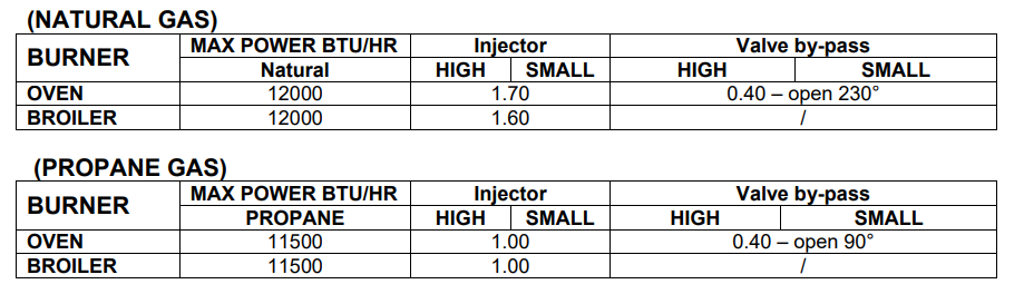
- Subsequently, using a 7 mm hexagonal wrench, loosen the injector “I” (fig. n° 13A) and replace it following the indications in the table “Oven gas burners technical data” –
- Injector (page 15). Re-mount the burner following the above described operations, but in reverse order, and following the instructions for adjustment of the by-pass.
- Save the orifices removed from the appliance for future use.
Adjustment by-pass
- Remove the thermostat knob. Using a small flat tip screwdriver, find the by-pass screws figures 11 and 11A).
- Turn right until the screw is completely closed. Then turn the bypass screw left by the number of degrees indicated in the Technical Data chart “Value by-pass” (page 15).
Appliance Pressure Regulator Conversion
- The unit appliance pressure regulator must be set to match the type gas supply used. If converting from natural gas to LP gas, the appliance pressure regulator must be converted to regulate LP gas.
- If converting from LP gas to natural gas, the appliance pressure regulator must be converted to regulate natural gas. To install the gas regulator you must use a CSA-certified Pipe Sealant only.
- To convert the appliance pressure regulator from one gas to another; remove the cap, push down and turn counter-clockwise. Turn the cap over and reinstall, follow the NAT or
LP indication (figure 12)
- LOW SETTING VALVE ADJUSTMENT The LOW setting should produce a stable flame when turning the knob from HIGH to LOW. The flame should be 1/8 inch or lower and must be stable on all ports on LOW setting. To adjust: Operate burner on HIGH for about five minutes to preheat burner itself.
- Turn knob back to LOW; remove knob, and insert a small flat tip screwdriver on left side slot (figs. 11 and 11A). Adjust the flame size by turning adjustment screw in either direction.
- Flame must be of sufficient size to be stable on all burner ports. If flame adjustment is needed, adjust ONLY on the LOW setting. Never adjust flame size on higher setting.
OVEN GAS BURNER TECHNICAL DATA