Loading ...
Loading ...
Loading ...
INSTALLATION INSTRUCTIONS
12
Inverter type model capacity (btu/h) 9K 12K 18K 24K 36K
Gas pipe diameter 3/8”
(ø9.52)
3/8”
(ø9.52)
3/8”
(ø9.52)
1/2”
(ø12.7)
1/2”
(ø12.7)
Additional refrigerant charge 20g/m 20g/m 20g/m 20g/m 30g/m
Other notes
• Liquid pipe diameter: 1/4” (ø6)
• Length of pipe with standard charge: 7.5 meters
• Maximum distance allowed between indoor and outdoor units: 15 meters
• Maximum difference allowed in level between indoor and outdoor units: 5 meters
• Type of refrigerant: R410a
Tightening torque for protection caps and fl ange connection
Pipe Tightening torque
(N x m)
Corresponding stress
(using 20 cm wrench)
Tightening
torque (N x m)
1/4” (ø6) 15 - 20 wrist strength service port nut 7 - 9
3/8” (ø9.52) 31 - 35 arm strength protection caps 25 - 30
1/2” (ø12.7) 35 - 45 arm strength
5.8” (ø15.88) 75 - 80 arm strength
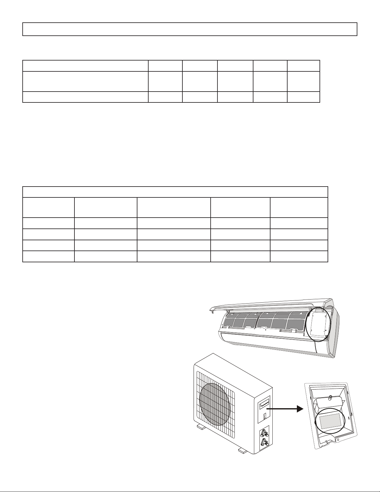
WIRING DIAGRAMS
The wiring diagram may be different for different
models. Refer to the wiring diagrams on both the
indoor and outdoor units.
On the indoor unit, the wiring diagram is located
under the front panel.
On the outdoor unit, the wiring diagram is located
on the back of the outdoor handle cover.
Note: Some models will have wires connected to
the main PCB of the indoor unit without a terminal
block.
INSTALLATION - INFORMATION FOR THE INSTALLER
Loading ...
Loading ...
Loading ...