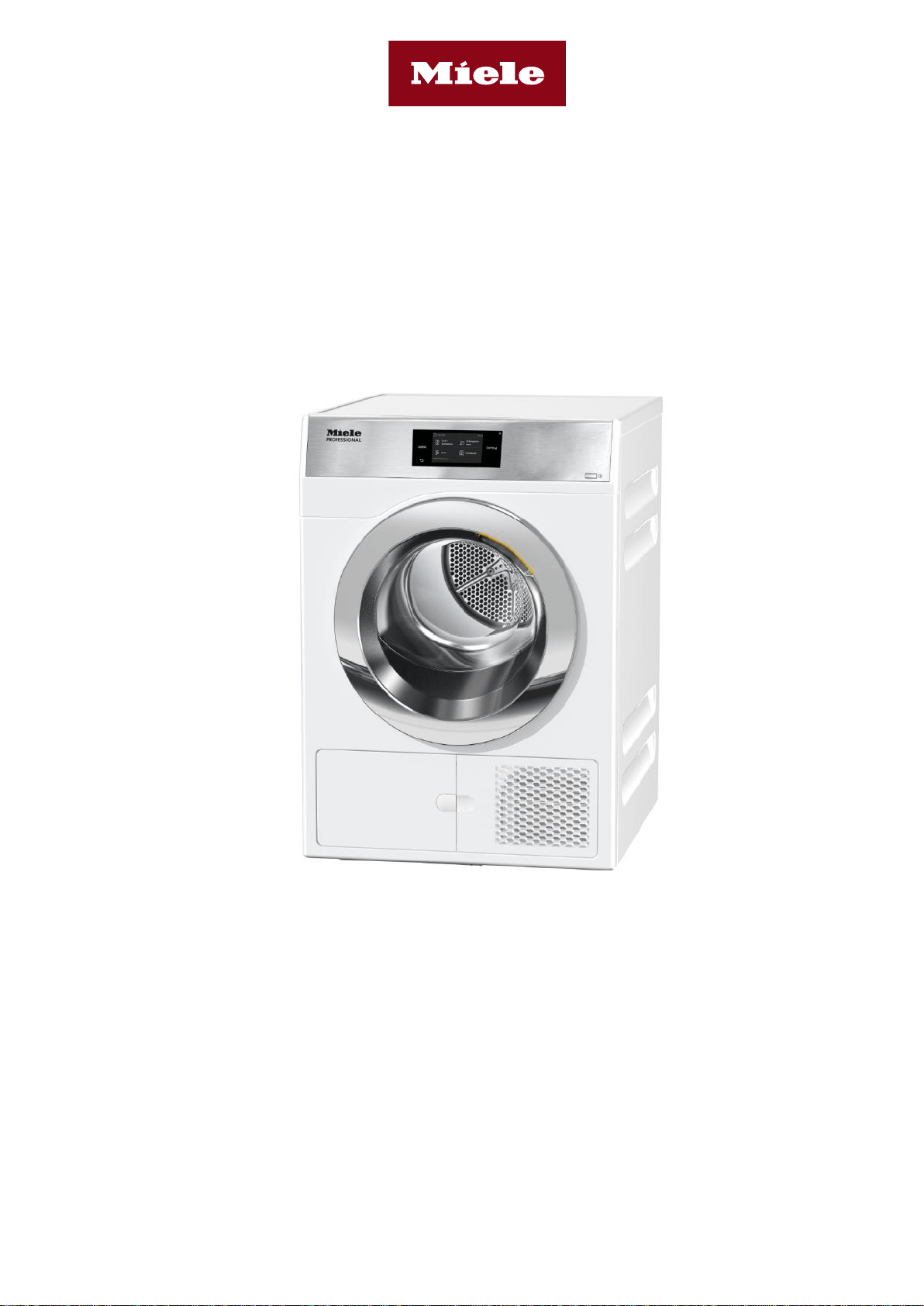
![PDR 908 HP [EL] photo](https://manualsfile.com/images/appliances/k2/in/k2ing2bnvhi_2_1654156567_thumbnail.webp)
Installation plan
Heat-pump dryer
PDR 908 HP
Always read the operating and installation instructions before
setting up, installing, and commissioning the machine.
This prevents both personal injury and damage to the machine.
en-CA
11 276 750/06

2 11 276 750/06
Please have the model and serial number of your machine available when contacting Technical Service.
Canada
Importer
Miele Limited
Professional Division
161 Four Valley Drive
Vaughan, ON L4K 4V8
Phone: 1-888-325-3957
www.mieleprofessional.ca
Miele Professional Technical Service
Phone: 1-888-325-3957
Manufacturer: Miele & Cie. KG
Carl-Miele-Straße 29, 33332 Gütersloh, Germany
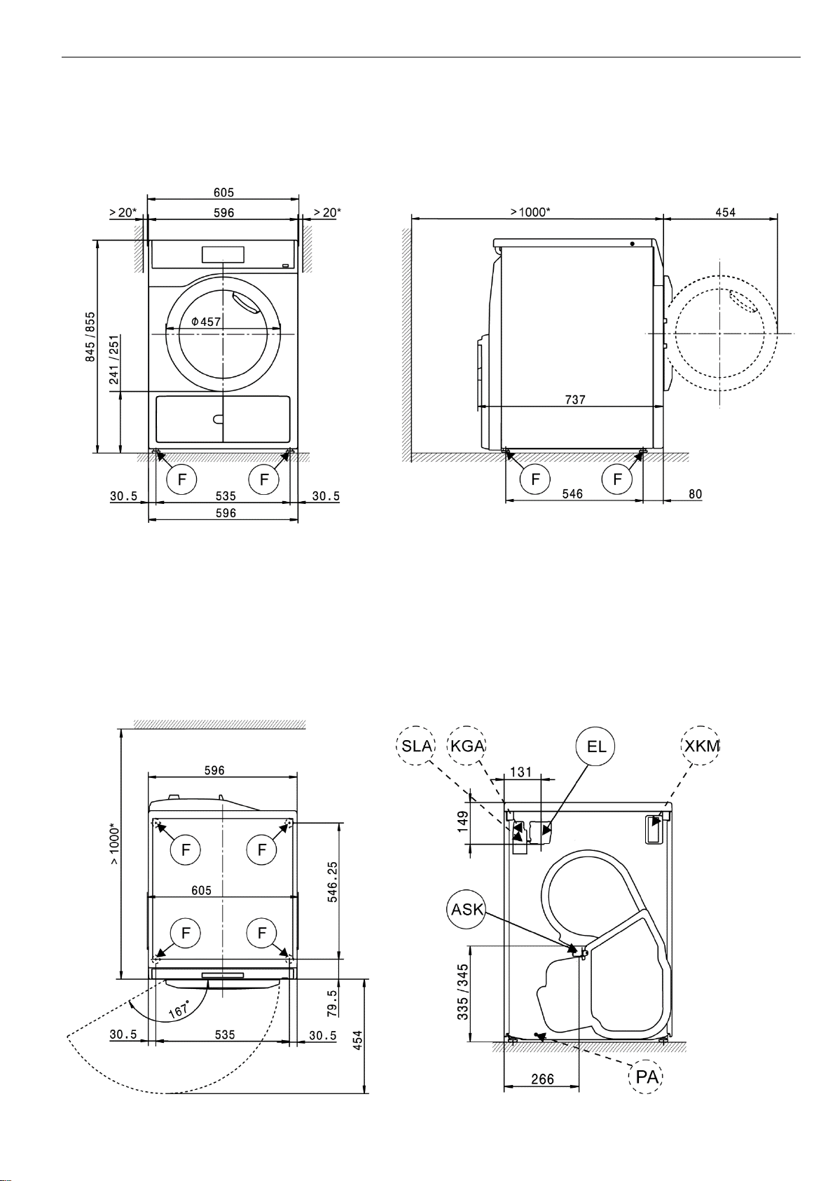
Legend:
Connection required
Connection optional or required,
depending on model
AL
Vented
KLZ
Cooling air intake
ASK
Condensate drain hose
PA
Potential equalization
B
Machine anchoring
SLA
Peak-load connection
EL
Electrical connection
APCL SST
Closed base
F
Machine feet, adjustable
APCL OB
Open base
KG
Payment system
APCL 001
Washer-dryer stacking kit
KGA
Payment system connection
XKM
Communication module
KLA
Cooling air vent
ZL
Air intake
All rights reserved.
PDR 908 HP en-CA
11 276 750/06 3
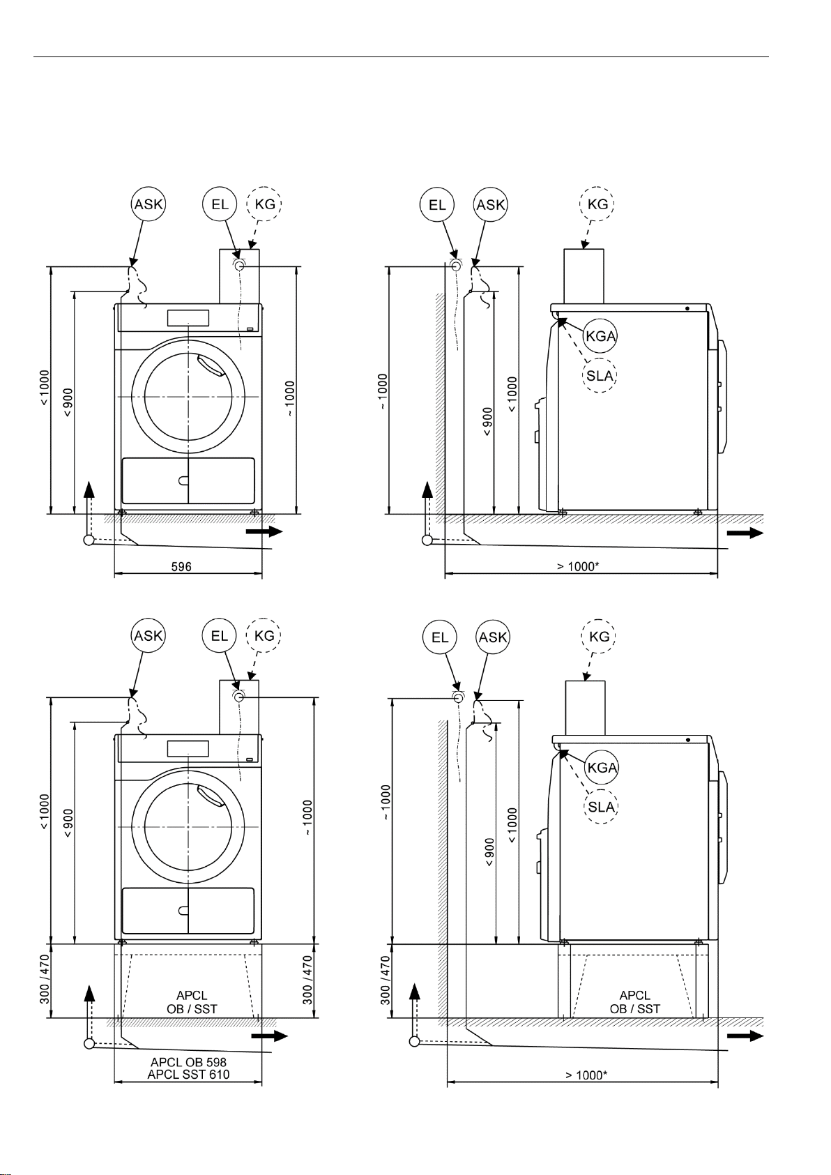
Machine dimensions
* The distances between the machine and the wall are recommendations to help make it easier to carry out service
work. If installation space is limited, the machine can also be pushed up against the wall.
PDR 908 HP en-CA
4 11 276 750/06
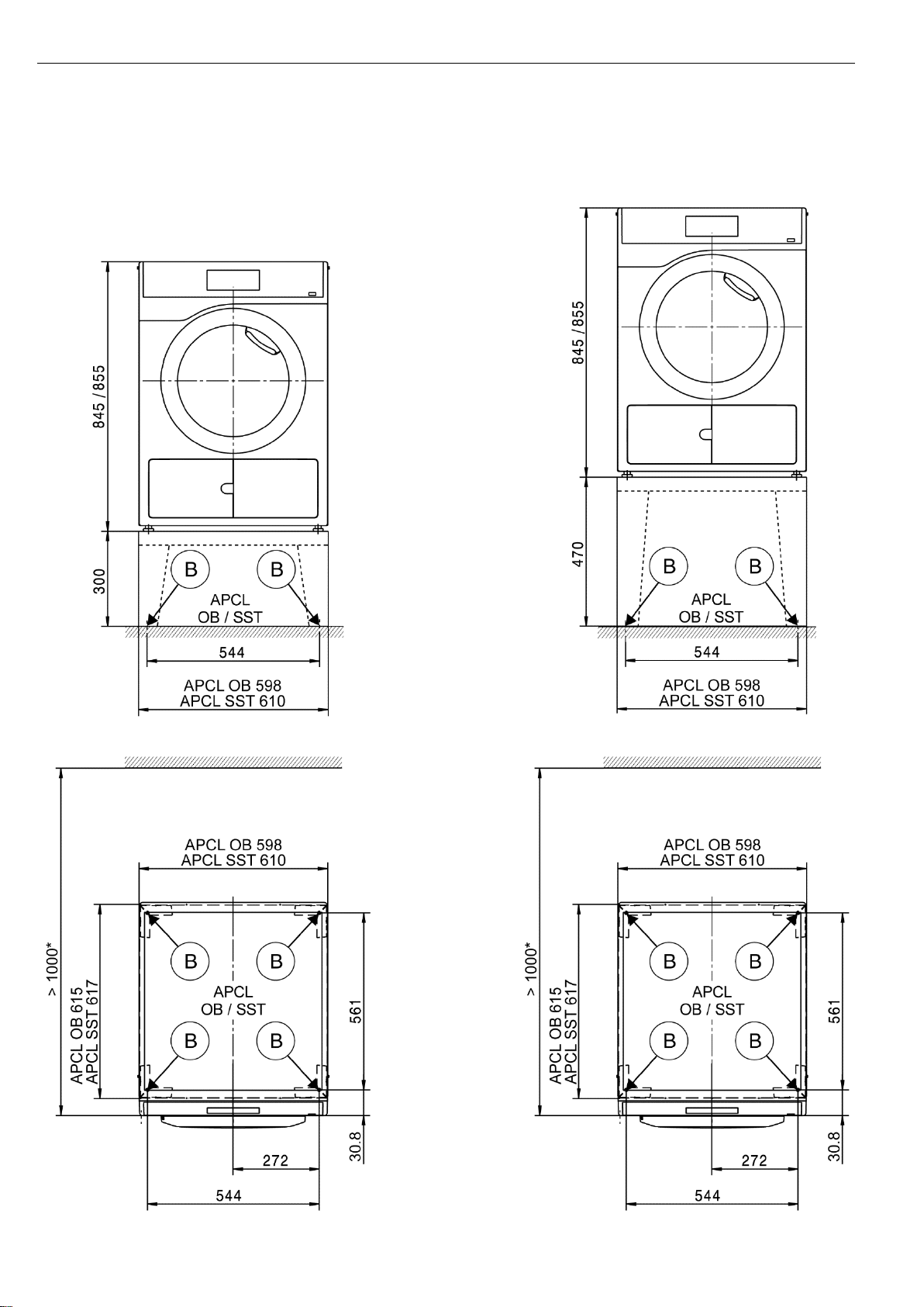
Installation
* The distances between the machine and the wall are recommendations to help make it easier to carry out service
work. If installation space is limited, the machine can also be pushed up against the wall.
PDR 908 HP en-CA
11 276 750/06 5
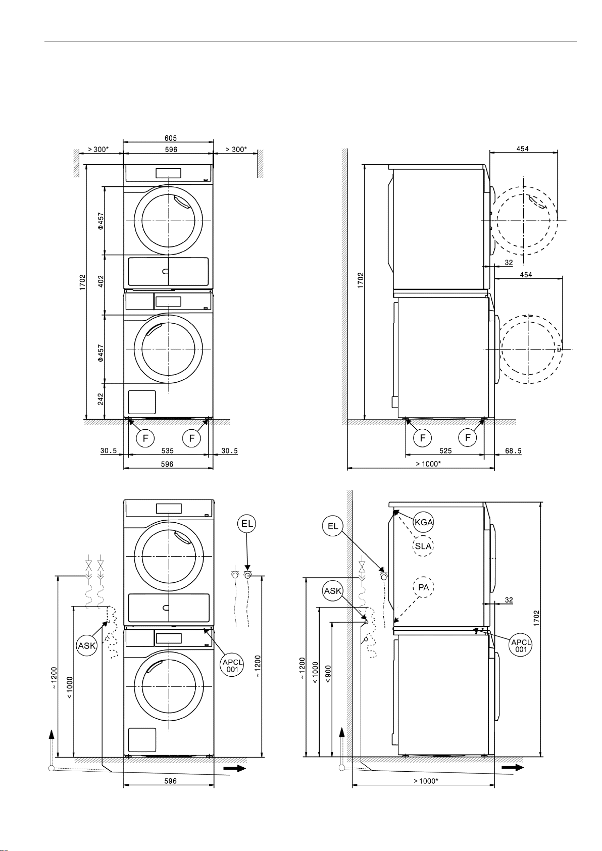
Washer-dryer stack
* The distances between the machine and the wall are recommendations to help make it easier to carry out service
work. If installation space is limited, the machine can also be pushed up against the wall.
PDR 908 HP en-CA
6 11 276 750/06
Installation
* The distances between the machine and the wall are recommendations to help make it easier to carry out service
work. If installation space is limited, the machine can also be pushed up against the wall.

PDR 908 HP en-CA
= standard, = optional, + = only on request, - not available
11 276 750/06 7
Technical data
PDR 908 HP
Drying system
Heat pump
Drum volume
l
130 (4.59 ft3)
Capacity
kg
8.0 (17.6 lb)
Door opening diameter
mm
370 (17 9/16 in)
Electrical connection (EL)
Standard voltage CDN & USA
2 AC 208–240 V
Frequency
Hz
60
Total rated load
kW
1.2
Fuse rating
A
2 x 30
Supply cable min. cross-section
3 x AWG10
Supply cable with plug type NEMA L6–30P
Length of supply cable
mm
2,100 (6.9 ft)
Non-standard voltage MAR 208–240 (Marine)
2 AC 208–240 V
Frequency
Hz
60
Total rated load
kW
1.2
Fuse rating
A
2 x 30
Supply cable min. cross-section
3 x AWG10
Supply cable with plug type NEMA L6–30P
Length of supply cable
mm
2,100 (6.9 ft)
Condensate drain hose (ASK)
Max. drainage temperature
°C
70 (158°F)
Max. transient flow rate
l/min
3.6 (0.95 gal/min)
On-site hose sleeve for drain hose
mm
10 x 30 (3/8 x 1 3/16 in)
Drain hose (internal diameter)
mm
10 (DN10)
Length of drain hose
mm
1,500 (4.9 ft)
Max. delivery head (from lower edge of machine)
mm
1,000 (3.3 ft)
Potential equalization (PA)
Machine connection (separate kit required)
XCI-Box / XCI-AD interface
Peak load/energy management (SLA)
Machine connection (with XCI-Box)
Payment system connection (KGA)
Connection of payment systems (with XCI-Box / XCI-AD)
Communication module (XKM)
Communication module XKM 3200 WL PLT
Installation on machine feet (F)
No. of machine feet
No.
4
Machine foot, height-adjustable with thread
mm
± 5 (3/16 in)
Machine foot diameter
mm
31.7 (1 1/4 in)
Anchoring (B)
Anchoring of Miele bases
Miele base installation (fasteners included)
Required anchor points
No.
4
Wood screws according to DIN 571
mm
8 x 65 (5/16 x 2 9/16 in)
Rawl plugs (diameter x length)
mm
12 x 60 (1/2 x 2 3/8 in)
Base floor anchoring (to be provided on site)
Machine installation on on-site base (concrete or masonry)
Min. base installation footprint (W/D)
mm
600/650 (23 5/8 x 25 9/16 in)
Wood screws according to DIN 571
mm
6 x 50 (1/4 x 2 in)
Rawl plugs (diameter x length)
mm
8 x 40 (5/16 x 1 9/16 in)

PDR 908 HP en-CA
= standard, = optional, + = only on request, - not available
8 11 276 750/06
Technical data
PDR 908 HP
Machine data
Overall machine dimensions (H/W/D)
mm
850/605/777 (33 7/16 / 23 13/16 / 30 9/16 in)
Casing dimensions (H/W/D)
mm
850/596/737 (33 7/16 / 23 7/16 / 29 in)
Site-access dimensions (H/W)
Min. site-access opening (excl. packaging)
mm
900/605 (35 7/16 / 23 13/16 in)
Installation dimensions
Side gap
mm
20 (13/16 in)
Recommended side gap – washer-dryer stack
mm
300 (11 13/16 in)
Recommended distance to opposite wall from front of machine
mm
1,000 (39 3/8 in)
Weights and floor loads
Machine weight (net weight)
kg
73 (161 lb)
Max. floor load in operation
N
925
Emissions
Sound pressure level (in accordance with EN ISO 11204/11203)
dB(A)
<70
Heat dissipation rate to installation site
W
950

PDR 908 HP en-CA
11 276 750/06 9
Installation and planning notes
Installation requirements
The tumble dryer should only be connected to a power supply
provided in accordance with all appropriate local and national
legislation and regulations.
In addition, all regulations issued by the appropriate utilities as well as
standards relating to occupational safety and all applicable valid
regulations and technical standards must be observed.
General operating conditions
Ambient temperature in installation room: +2°C to +35°C (36°F to
95°F).
Air drawn in for use in the drying process will be warm when it is
expelled back into the room. You must therefore ensure that the room
is sufficiently ventilated, particularly if the dryer is located in a small
room.
Make sure that the room temperature is not too high. If there are other
heat-producing appliances in the room in which the dryer is located,
make sure the room is well ventilated and switch the other appliances
off, if possible.
Otherwise running times and energy consumption could be increased.
Electrical connection
This tumble dryer is supplied with a power cord and plug ready for
connection.
The machine may only be connected to an electrical system that
conforms to the national and local codes and regulations.
The tumble dryer should never be connected by an extension cord,
e.g. power strips, to avoid the risk of fire.
The data plate indicates the nominal power consumption and the
appropriate fuse rating. Compare the specifications on the data plate
with those of the electrical power supply.
If the machine is hard-wired, a dual circuit breaker must be provided
on site. When switched off, there must be an all-pole contact gap of at
least 3 mm in the isolator switch (including circuit breakers, breakers,
and relays according to IEC/EN 60947).
The plug connector or isolator switch should be easily accessible at all
times. If the machine is disconnected from the electricity supply, the
isolator must be lockable or the point of disconnection must be
monitored at all times.
New connections, modifications to the system, or servicing of the
ground conductor, including determining the correct fuse amperage,
must be carried out by a qualified electrician, as they are familiar with
the pertinent regulations and the specific requirements of the electric
utility company.
References to cable cross-sections in the technical data refer only to
the required power cord. Please consult relevant local and national
regulations when calculating any other wire gauges.
Condensate drain hose
The condensed water is pumped away through the drain hose which
is located at the back of the dryer.
The condensate is drained via a drain pump with a 1 m (3.3 ft)
delivery head. For the water to drain freely, the hose must be installed
free of kinks. The swivel elbow at the end of the hose can be turned in
either direction or removed as needed.
In certain situations, this tumble dryer must be fitted with a non-return
valve (optional accessory). Without a non-return valve, water could
flow back into the tumble dryer or be drawn back in and leak out. This
can cause damage.
Drainage options:
1. Direct connection to a plastic drain pipe with a rubber sleeve.
Use a non-return valve if the end of the hose could possibly
become submerged in water.
2. Connection to a sink with a plastic nipple.
Always use a non-return valve.
3. Connection to a floor drain (gully).
Always use a non-return valve.
4. Directed into a sink or basin.
Secure the drain hose carefully (e.g. by tying it) to make sure it
cannot slip. Otherwise water may escape and cause damage.
Use a non-return valve if the end of the hose could possibly
become submerged in water.
Potential equalization
If necessary, potential equalization with good galvanic contact must
be guaranteed in compliance with all applicable local and national
installation specifications.
Connection material for potential equalization must be provided on
site or using a kit available from Miele Service.
Peak load/Energy management
The tumble dryer can be connected to a peak load or energy
management system using an optional kit.
When the peak-load function is activated, the heating is deactivated.
A message appears in the display to inform you of this.
Payment system
The tumble dryer can be fitted with a single-machine payment system
as an optional accessory using an optional kit (XCI-Box / XCI-AD).
The programming required for connecting a payment system can be
carried out during the initial commissioning process. After initial
commissioning, changes may only be carried out by your Miele dealer
or Miele Service.
Interface
The tumble dryer can be retrofitted with an XKM 3200 WL PLT
communication module.
This module can be used as a WiFi or LAN interface.
The LAN interface provided via the module complies with SELV
(Safety Extra Low Voltage) in accordance with EN 60950. Connected
appliances must also comply with SELV. The LAN connection uses a
RJ45 connector in accordance with EIA/TIA 568-B.

PDR 908 HP en-CA
10 11 276 750/06
Installation and anchoring
The machine must be installed on a perfectly smooth, level and firm
surface which is able to withstand the quoted loads.
The floor load created by the machine is concentrated and transferred
to the installation footprint via the machine feet.
The tumble dryer should be levelled in both directions with the aid of
the adjustable feet.
Base installation
The tumble dryer can be installed on a machine base (open or box
base, available as an optional Miele accessory) or on a concrete base
to be provided on site.
The quality of the concrete and its strength must be assessed
according to the machine load. Ensure that any raised concrete base
is adequately bonded to the floor below.
Washer-dryer stack
The tumble dryer can be installed as a washer-dryer stack together
with a Miele Washing Machine. A stacking kit (optional accessory) is
required for this.
Installation of the stacking kit must be performed by Miele Service or
an authorized Miele service technician.