
Operator's manual (CARB II) /r _
326P4 326P4x.SER, ES
326P5x.SER, ES
Please read these instructions carefully and make
sure you understand them before using the machine. English

SYMBOL EXPLANATION
Symbols
WARNING! Tiffs nlachine can be
dangerous. Cra'eless or incorrect use
can _x_sultin serious or Fatal inlury lo
the operator or others,
Read through the Operaior's Mramal
can_thlly and under.lined the con*ent
before uMng the machine.
Always use
• A protective hehnet where there Ls
a rLsk of falling ol_jecis
• Era' protection
• Approved eye proteciion
• ]'hks product ksin accordance wtth
applicable CE direciives.
• This machine Lsnot electrically
insulated, If the machine louches
or conies close to high-voltage
powra' lines it could lead to death
or serious irlluW, Eleciricity can
.jump Dom one point to another by
arcing. The higher the voltage, the
g*xmterthe distance electdctty can
.jump Electricity cra_also travel
itu'ough branches and other
oblects, especially if th W are wet.
Alwayskeep a safe dLstm_eeoFat
least I0 ni ('30It) between the
machine and high-voltage power
lines and/or aW ot_ieelsthat are
iouct_ng them. If you need to
wo*Ckcloser than this alwws
coniact the *xd_'m_tpower
company to make sure the power is
switched oFFbefore you stra_ wo*¢k.
• Tiffs n_tchine has a long reach.
Make sure that no people or
animals come closer limn 15 m (45
FI)when the machine is running.
• Alwws wear approved protective
gloves,
• Use anti-slip ra_d siable boots,
Other symbols!decals on the machine refer to
special certification requirements for certain
markets.
• Checks ra_dior rnainlenance should
be carried out with the engine
swiiched off, with the stop swilch
in the STOP position.
• Alwws wear approved protective
gloves,
• Regulra' cleaning required.
• Oculra' comroL
• Approved we protec{ion mus{
always be u_sed.
• Chain oil ra_dchain offflow
adJtLstnlem
- Ee<41sh
CONTENTS
Husqvarna AB has a policy of continuous product dev*dopment
zmd therefotx_ reserves the right to modify the design and
appe_'ance of products wit}tout prior notice,
Maintenance, replacement, or repair of the emission control
de_ices and systems may be performed by any nonroad
engine repair establishment or individual
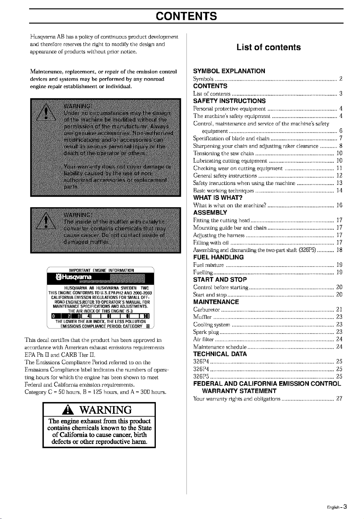
IMPORTA_f ENGINE INFORMATI01_
']'iris decal certifies that the product has been approved in
accordance wtth American exhaust emissions tx_qui*x_ments
EPA Ph [I and CARB Tier II,
The Emissiom Compliance Period referred to on the
Emkssioos Compiiance label indicates the nvnibet's of opera-
ling hou*'sfor which the engine has been shown to meet
Federal and California emkssion requiremems.
Category C = 50 hours, B = 125 hour, and A = 300 hours,
WARNING
The engine exhaust from this product
contains chemicals known to the State
of California to cause cancer, bh'th
defects or other reproductive harm.
List of contents
SYMBOL EXPLANATION
Symbols ............................................................................... 2
CONTENTS
L_st of contents ................................................................... 3
SAFETY INSTRUCTIONS
Personal protec_ve equipment ............................................. fl
The machine's safety equipment .......................................... 4
Comroi maintenance and service of fhe nlachine's safety
equipment ................................................................. (_
Specification of blade and chain ......................................... 7
Sharpening you*'chain and adjusting rakes clearance ........... 8
*I_nsiontng the saw chain ................................................... 10
Lubricating cutting equipment ......................................... 10
Checktng wear on cutting equipment ................................ ] 1
General safety tnsu'uctions ................................................. 12
Safety JnsI_ctioI'IS_ghen tLstng the machine ........................ 13
Bastc worktng techniques ................................................... 14
WHAT IS WHAT?
What is what on the machin_ ........................................... 16
ASSEMBLY
[qtting the cutting head ...................................................... 17
Mounting guide 13_' mad chain ........................................... 17
A({}usting the tmrness ......................................................... 17
Filling wtlh oil ................................................................ 17
_'-g'mMing and dtsmantlirg the t_vo-p_ sl_fl (326P5)........... 18
FUEL HANDLING
Fuel mlxtur_ .................................................................... 19
Fueliing ............................................................................. 19
START AND STOP
ContmI b_fotx_starting ....................................................... 20
St_'t and stop ..................................................................... 20
MAINTENANCE
Carbu*x_tor......................................................................... 21
_uffler ............................................................................ 23
Cooling system .................................................................. 23
Spark plug .......................................................................... 23
Air filter ............................................................................. 24
Matntenance schedule ........................................................ 24
TECHNICAL DATA
326P4 .............................................................................. 25
326P4 ................................................................................ 25
326P5 ................................................................................ 25
FEDERAL AND CALIFORNIA EMISSION CONTROL
WARRANTY STATEMENT
Your warranty t'tghts and obltgattons .................................. 27
English - 3
SAFETY INSTRUCTIONS
Personal protective equipment
IMPORTANT INFORMATION
If used incorrectly or carelessly this machine
can become a dangerous tool that can cause
serious or fatal injury to the operator or others. It
is extremely important that you read and underst-
and the content of this manual.
When using the machine, personal protective
equipment approved by the appropriate
authorities must be used. Personal protective
equipment does not eliminate the risk of
accidents. However, it can reduce the effects of
an injury in the event of an accident. Ask your
dealer for help when choosing protective
equipment.
GLOVES
Gloves must lie worn
whenemer required, for
example when fitltng,
inspeciing or cleaning
culling equipment,
PRO FEC FIVE HELME 1'
AND VISOR
EAR PROTEC I'[ON
Ear protecllon offering
sufficient dampening elfeel
should be used,
EYE PRO FEC ]'ION
Blmvs from branches or
oblects thrown out by the
culling equipmeni can
damage the eyes.
BOOTS
Use anti-slip and siable
boots,
CLOTHING
Wear clothes made of a
sirong fabric mid avoid loose
clothing that can ealch on
shrubs and branches, Always
wear heavy, long pants. Do
not werw jewelry, sho_9
paros, sandals or go bmx_fooh
Secure hair so tt is above
shoulder level.
FIRS']' AID KIT
The operator musl carry a
first aid kiL
The machine's safety equipment
Thks seeiton desca'ibes the machine's safety equipment, Its
function and how checks m_d mainlenm_ee m_ em_'ied o_t to
e1_.surethai; tt operatvs corr_ctI 5 (See the chaplet "WDat is
wDat"to locate where thks equipment ks positioned on your
machine,)
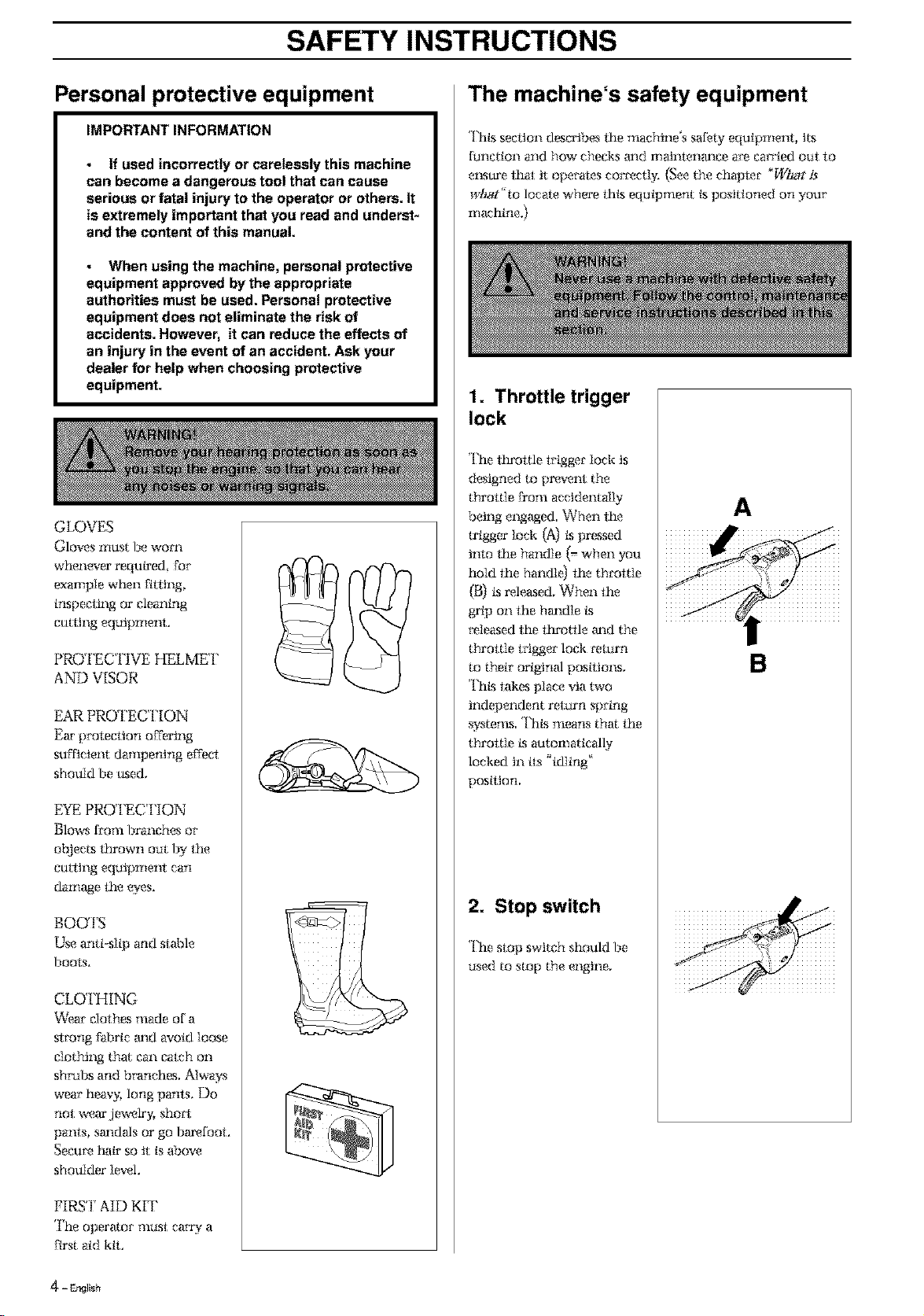
1. Throttle trigger
lock
The throttle lrigger lock ts
designed to pr_,ent the
throttle Dora accidental]>,
being engaged When lhe
trigger loci{ (A) ks pressed
hlto the handle (=when you
hold the handl_t the throltle
(B) ksreleased, When the
grip on the hm_dle ks
*_leesed the ttu'otlle m_d the
throttle trigger lock celurn
to their original postties_s,
<['titstakes place via two
independent relm'n spring
systems Thks means tha the
throttle ks automatically
locked tn its _idling'
position,
2. Stop switch
The stop switch should be
used to stop the engine,
A
B
4 - EP,gllsh
SAFETY INSTRUCTIONS
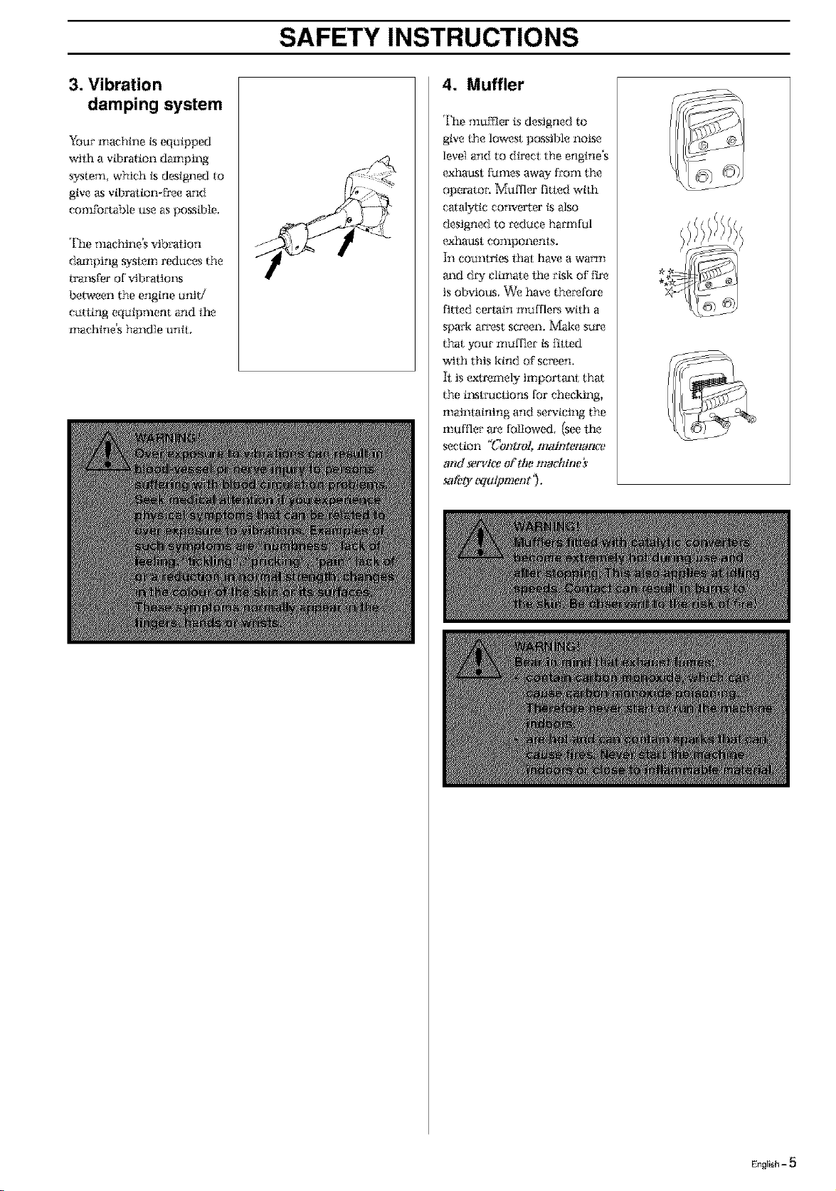
3. Vibration
damping system
Your nlachine ksequipped
wtlh a vibration damping
system, which ksdesigned to
give as vii)ration-free and
comfoaable use as posstble,
The machine's vibraiton
daznping _'slem reduces the
traP.sfer of vtbi'atioP.s
between the engine unit/
catting equipment and the
nlaehine's handle untL
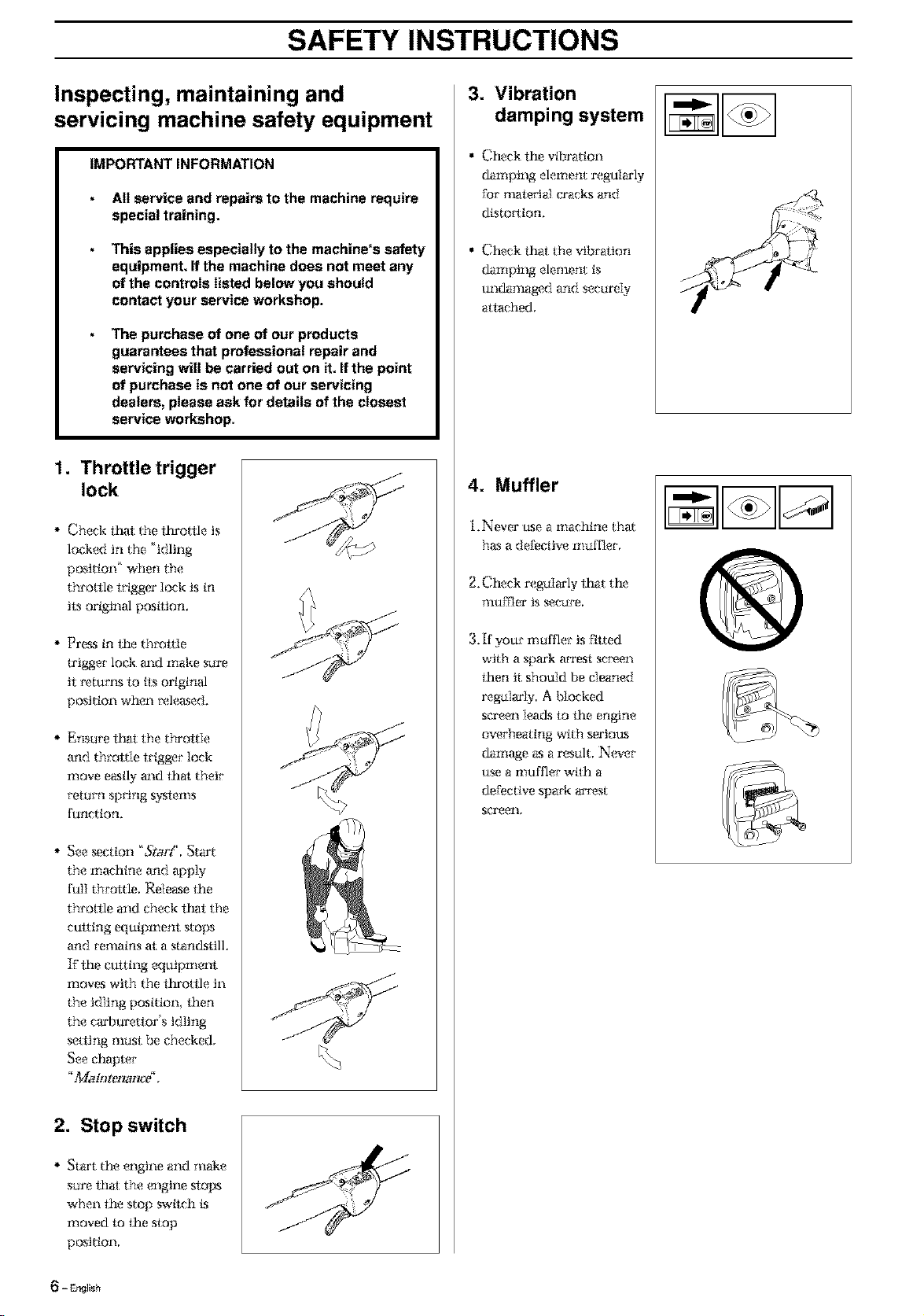
4. Muffler
The mumer is designed to
give the lowest possible noise
level and to direct the engine's
exhat_st fumes away from the
operator: Muffk,' fitted wtth
catalytic converter ksalso
designed to *_duee hamfful
(_haust components.
In countries lhat have a warm
and dW climate lhe risk of fire
is obvious. _'e t_lve the_'efore
fitted certain nmffle*_ with a
spark arrest sca_,_en.Make s_r_
that your hi,If fief ks fitted
with this kind of screen,
h: is (_tremely importm_i tha
the i1_stcoctions for checking,
mainlaining and servicing the
nmffler am followed (see lhe
section _Control, maintenantv
and *t,rvice of the machine}
_1_'0" WuiP merit '},
.1111111111
English = 5
SAFETY INSTRUCTIONS
Inspecting, maintaining and
servicing machine safety equipment
IMPORTANT INFORMATION
All service and repairs to the machine require
special training.
This applies especially to the machine's safety
equipment. If the machine does not meet any
of the controls listed below you should
contact your service workshop.
The purchase of one of our products
guarantees that professional repair and
servicing will be carried out on it. If the point
of purchase is not one of our servicing
dealers, please ask for details of the closest
service workshop.
1. Throttle trigger
lock
Check t_l: the ttn'o/tle is
locked in the 'idling
position' when the
throttle trigger lock is in
its original postlion,
Press in the throttle
u'igger lock m_d make sure
it i_turl_,slo its original
position when _xdeased.
Ensure t_t the throttle
and throl:tle trigger lock
move easily and thai; their
return spring systems
function.
* See section 'StorY, Start
the machine and apply
full throttle, Release the
throAle and check that the
cutting equipment stops
and remains at a stan_kstilL
If lhe cutting equipment
nloves with the fhrottle in
the idling position then
the craq]urettor's idling
setting must be checked,
See chapter
_+%.Ioh)ten_nag,
J
2. Stop switch
Start the engine and make
sure thai; the engine ,slops
when the stop switch ks
moved to the stop
position,
3. Vibration
damping system
• Check the vfl)ration
damping element regularly
for illatelJal cx'acks and
distortion,
• Check that the vibration
damptog elenlent is
undamaged and securely
attached,
4. Muffler
i.Never use a nlachine that
has a defective muffler,
2. Check regaIarly lhat the
muffler is secure,
3. If your muffler is ftlted
with a spark arrest sc_x_en
then it should be cleaned
regularly A Socked
screen lea(ks to the engine
overheating with sertou_s
damage as a result. N(wer
use a muffler wtlh a
defective spark ar_x_st
screell,
- EP4_Ish
SAFETY INSTRUCTIONS
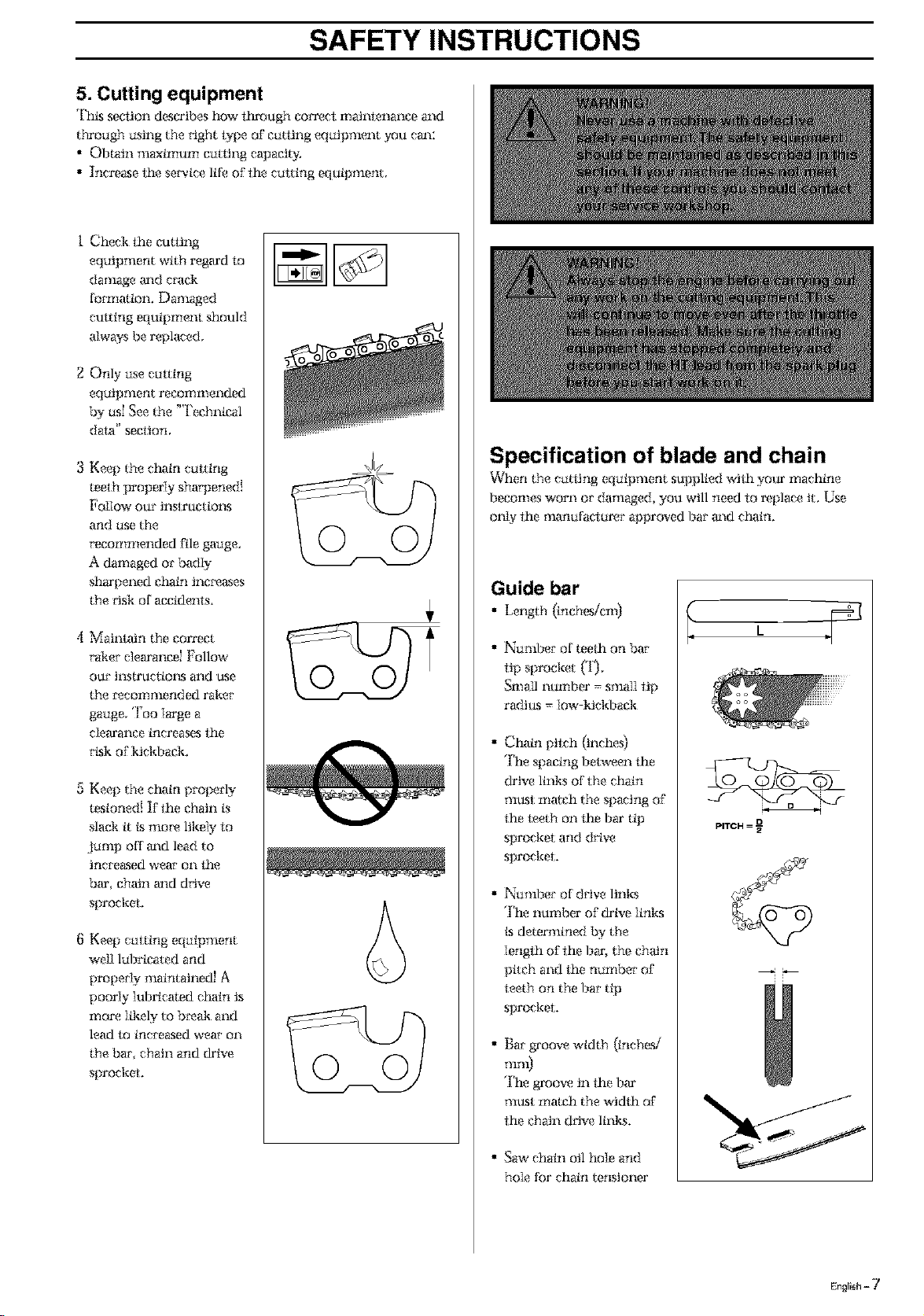
5. Cutting equipment
ThLs section describes how f_ough corix_et maintenance and
through using the _Jght t91)e of cutting equipment you can:
• Obtain maximum curling capacity.
• Increase the service life of the cutting equipment.
i Check the cutting
equipment with regard lo
damage m_d era(k
formaion. Damaged
cutting equipment should
always be replaced.
2 Only use cutting
equipment recommended
by us_ See the "l'echnical
data" secllon,
3 Keep the chain cutting
teeth properly sha_ened!
Follow our instructiol_s
and use the
recommended file gauge,
A damaged or badly
sharpened chain inc*x_ases
the *'isk of accidenls.
4 Maintain the correct
*'ake*"elearancd Follmv
our instructim_,sand use
the *'eeommended raker
gauge, Too ]arge a
c]earance increases ihe
rLgkof kickback,
5 Keep the chain properly
tesioned! If the chain is
slack it Ls mo_x_ likely to
Jump off m_d lead to
increased wear on i_e
bar chain m_d drive
sprocket.
8 Keep cutting equipment
wd] lubricated and
propeiqy nmintained! A
poor{y iubricated chain is
nlore ]ikely to b*x_akand
lead to increased wear on
the bar chain and drive
sprocket,
© ©
© ©
Specification of blade and chain
Vv'her the cattir g equipnient supplied with your nlaehine
becomes worn or damaged, you will need to replace it. Use
only the manufactar<_r approved bar and chain.
Guide bar
• Length (inchesicni)
• Number of teeth on bar
tip sprocket (*1).
Small number = small tip
radius = low-kickback
• Chain pilch (inches)
The spacing between lhe
drive links of the chain
must nlatch the spacing of
the leeth on the bar tip
sprocket and drive
sprocket,
• Number of drive links
The number of drive ]inks
Lsdetermined by the
]engfh of ihe bar, the chain
pitch and the number of
leeth on the bar tip
sprocket,
• Bar g*'oovewidth (inches/
TlllI1)
The groove in the bar
must match the width of
the chain d*Jve links.
• Saw chain oil hole and
hole for chain tensioner
PITCH = D
English - 7
SAFETY INSTRUCTIONS
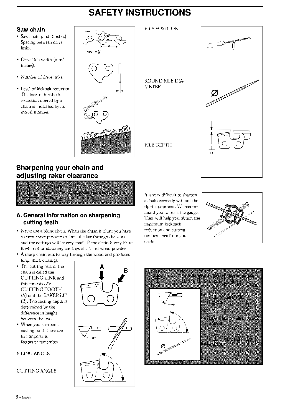
Saw chain
Saw c_in pitch {inches}
Spacing between drive
links,
Drive link width (ram/
inch_.
Namber of drive links.
Level of kickbak _duciJon
The level of kickback
_'educlion offered by a
chain is indicated by its
r! iodeI nu;llbec
PITCH = D
Sharpening your chain and
adjusting raker clearance
A. General information on sharpening
cutting teeth
* Nexer use a bIunt chain. When lhe chrdn is blunt you have
to (_e_ rno_ p_?ssure to force the bar lhrough the wood
and the cutiin_s will be vec¢ sinai1, F the chain ks very bIunt
it will not produce any cm:tings a all just wood powden
A shaq) chain eats ils way through the wood a_d produces
long, lhick cutiings.
The curling part of the
chain ks called lhe
CUTTING LINK and
this consists of a
CUT'IING TOOTH
(A) and the RAKER LIP
(B). The curling depfli is
determined by the
difference in height
between the two.
When you sharpen a
culting looth there are
five important
faciors to _a_llellfl)er;
FILING ANGLE
CUT I'ING ANGLE
0 0
FILE POSI I'ION
ROUND FILE DIA-
METER
FILE DEP I'H
h is ve W difficult to sharpen
a chain corr_ctly without the
_'ight equipment, _e recom-
mend you to use a file gauge,
This will help you obtain lhe
maximum kickback
_duction and culting
perfomlance froTll yOUI"
chain.
5
8 - DNIsb

SAFETY INSTRUCTIONS
the i_turn sl:_'oke.
File all the teeth on one
B. Sharpening
cutting tooth
'lb shaq)en catting teeth you
wiIl need a ROUND FILE
and a FILE GAUGE.
i. Check t_l: the chain is
correctly le1_aioned. A
slack ctmin is difficult to
sharpen cora'eclly.
2, Always file ctltting leeth
from the inside Nee
*'educing the pressure on ............................................................................
side First then turn the
machine over and file the
teeth on the other side.
3. File all the teeth to the
same length. When the
length of the culting leeth
is reduced m 4 mm (.16")
the chain ksworn out and
should be repIaced.
min 4 mm
C. General advice on setting raker
clearance
When you stmrpen the
curling teeth you reduce
the RAKER
CLEARANCE (crating
depth), *lbmaintain
cutting perFornmnce
you musl file back the
raker leeth to the
recommended height,
On a Iow-ktcM)ack
curling link the Front
edge of the raker iip ks
rounded, It ksveW
important f_t you
mainIatn thLs radius or
bevel when you adjust
the raker clearance,
We recommend the use
of a taker gauge m
act_eve the cors_ct
clearm_ce m_d bevel on
the taker Iip,
i
0
English - 9
SAFETY INSTRUCTIONS
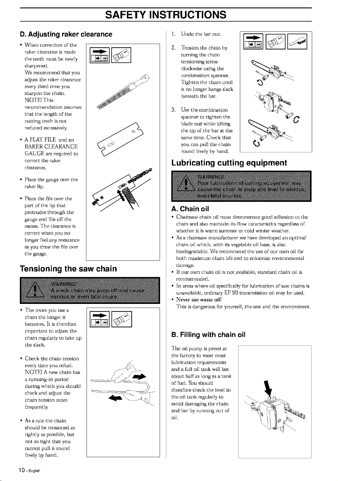
D. Adjusting raker clearance
When correctionof the
taker clearance ks made
the teeth mu_ be newly
sharpened,
"v_'erecommend that you
adjust the rarer clearance
(_,e W third lime you
sharpen the chain,
NOTE{ l'his
*x_commendation assuIlles
that the length of the
cuiting leeth is not
*_dueed excessively.
A FL_iF FILE and an
RAKER CLEARANCE
GAUGE a_ *x?quimdto
correct the rarer
clearance,
Place the gauge over the
rarer lip,
Place the file over the
part of the Ilp that
protrudes through the
gauge and Fileoff the
excess,The clearance is
correct when you no
longer %el aW msistm_ce
as you draw the Fileover
the gauge.
Tensioning the saw chain
• The more you use a
chain the longer it
becomes. It is the_fore
important to adjust the
chain Ix_gularlyto take up
the slagk.
• Check the chain tension
evew time you refuel
NOTE! A new chain h_s
a running-in period
during which you should
check and adjust the
chain tension more
ffequentI5
• As a rule the chain
should be telxsioned as
tightly as possible, but
not so tight lhat you
cannot pull it round
Freely by hand.
i.
2.
3.
Undo the bar nut,
*lhxslonthe chain by
turning the chain
tensioning sca'ew
clockwise using the
confbination spmmer.
Tighten the chain until
it no Iongar hangs slack
beneath the bar.
Use the combination
spramer to tighten the
blade nui while lifting
the lip of the bar at the
same time, Check _t
you can pull the chain
round Dedy by hand,
Lubricating cutting equipment
A. Chain oil
• Chainsaw chain oil must demonstrate good adhesion to the
chain m_d also narintain tls flow caracterkstics regardlexs of
whethar it is warm SUTI1TIleI'Orcold winter weather.
• As a chainsaw rNanufactu*'(_r we have dexeloped an optimal
chain oil which with tla vegetN)le oil base ks also
biodegg'add_ie. We recommend the use of our own oil for
both m_lmum chain life and to minimkse environmental
dare.e,
• If our own chain oil is not available, standard chain oil ks
recommended.
• In areas where oil specifically for Iubrieaiion oFsaw chains is
unavailable, ordina W EP 90 trm_smLssionoiI mW be used,
• Never usewaste oilI
This ksdangerous Foryourself, the saw and the environmenl.
B. Filling with chain oil
The oil pump is pr_set at
the facto W 1o meet most
lubrication requirements
m_d a full oil tank will last
aboui half as long as a tm_k
of Fuel, You should
therefore check the level in
the oiI tank regularly 1o
avoid damaging the chain
a_d bar by running out of
oil,
1 0 - Engrish

SAFETY INSTRUCTIONS
C. Checking chain lubrication
• Check the chain
hlbrication each time you
refuel,
Aim the tip of the saw at a
light eolotwed sta'faee
abo_t 20 cm away. Aries
i minute running at 3/4
throttle you sho_Id see a
distinct line of oil on the
light surface.
D. Adjusting chain lubrication
• Vqhen catting dry or hard
species of wood tt m%,:- be
necessaWto increase
l_brieation, To increase
the oil flow, final:undo
screw (A)then mm the
adjuster screw (B)
antielockwise. Re-tighten
screw (A). Remen/ber that
this will increase the oil
COl_Sump[ionand you
should the_ffoI_ check the
k_,el in the oil tank Tllo_'(}
Dequenfly,
B
Procedure if the lubrication does not
function:
• Check that the oil channel
in the bar is not
obstructed. Clean if
1 leeessai_L
Check also that the O-
,-ing is in position and is
tmdamaged,
• Check that the oil ctmnneI
in the gear ho_sing is
clemL Clean if necess,_'y.
• Check that the bar tip
sprocket lurns freely, F
the chain l_briealion
system ksstill not working
afler carrying oui the
above me_sures you
should contact yonr
service agenl.
Checking wear on cutting equipment
A. Saw chain
Check the saw chain daily
for;
• Visible cracks in rivets
and 1inks
• Whether the chain is siifI'.
• _¥hather rivets m_d links
are badly worn,
Compare the exgting chain
with a new chain to decide
how badly il is worn,
When thelength of the
curling leeth has worn
down to only 4 mm the
chain m_st be repIaeed.
B. Chain drive wheel
Check reg_laJ'lythe degree of
wear on the drive wheel,
Change ff tt is irregtllraqy
worrL
I I min 4 mm
C.Vibration damping
system
Check_gularly that the
vibration damper i free from
cracks.
Check regularly the degree of
we_' on the r_bber elements.
Chm_geif worn
D. Guide bar
Check _x_gnlarly:
• Whether there am bur_
on the edges of"the bar,
Remove these with a file if
necexsary.
• Whether the groove in the
bar h_s become badly
worn. R_pIaee the bar if
necexsary.
• Whether the tip of the bra'
is uneven or badly worn.
[f a hollow forms on one
side of the bar lip this is
due to a slack chain.
• 'lb prolong the life of the
bar you should turn it
over daily.
\
SAFETY INSTRUCTIONS
General safety instructions
IMPORTANT INFORMATION
The machine is only designed for tree pruning.
The only accessories to be used with the engine
unit as a drive source are the cutting units we
recommend in the chapter "Technical data%
Never use the machine if you are tired, if you
have consumed alcohol, or if you are taking
medicines that can affect your sight, your
judgement or the control of your body.
Use personal protective equipment. See the
section "Personal protective equipment%
Never use a machine that has been modified so
that it no longer corresponds with the original
design.
Never use a machine that is faulty. Follow the
maintenance, control and service instructions in
this Operator's Manual. Some maintenance and
service actions should be carried out by trained
and qualified specialists. See the chapter
"Maintenance".
All covers and guards must be fitted before
starting the machine. Check that the spark plug
cap and HT lead are not damaged, otherwise you
could get an electric shock.
The machine operator shall ensure, while
working, that no persons or animals come closer
than 15 metres (50 fset).When several operators
are working in the same area the safety distance
should be at least double tree length, however, at
least 15 metres (50 feet).
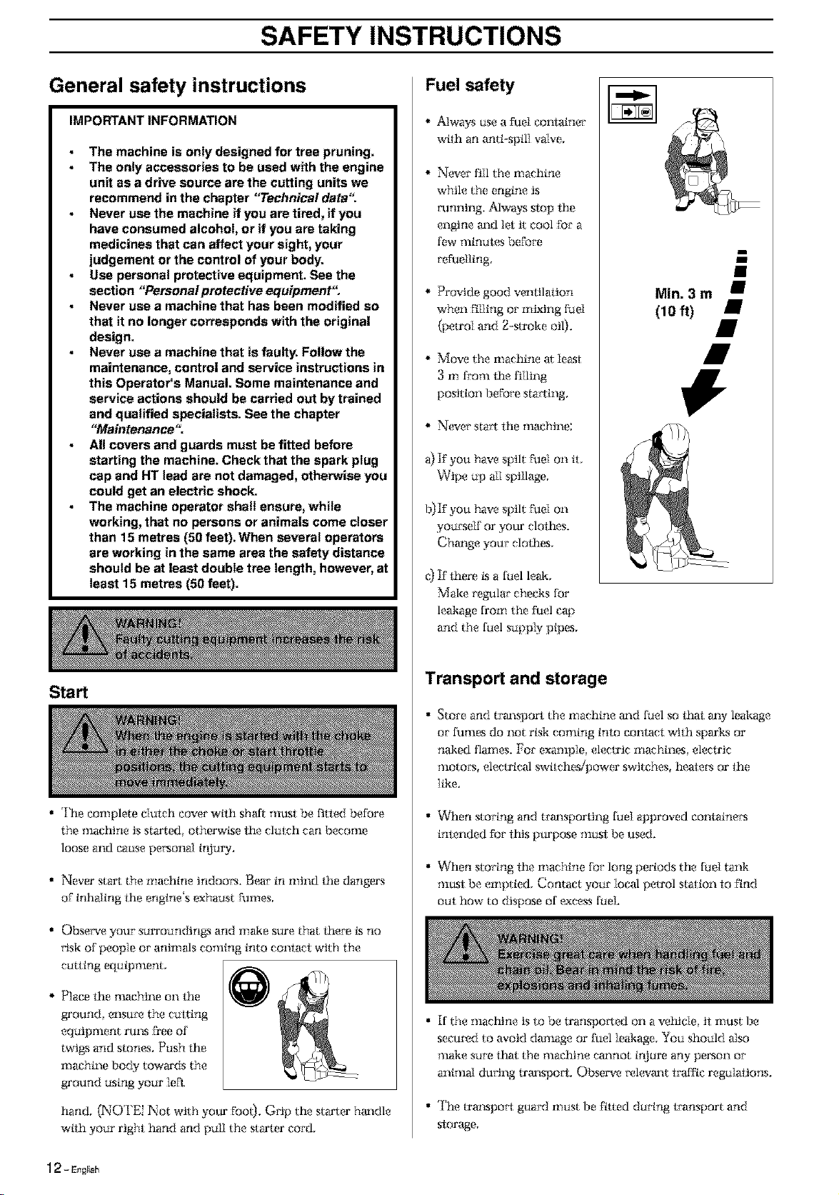
Start
• The complete dutch cover with shaft must be fitted before
the *llaehirleis started, otherwkse the clutch can become
loose and cause pecsonal i*lluW.
• Never start the machine indoors. Bear in mind the dangers
of"inhaling the engine's exhaust fumes,
• Obser_,eyour sun'oundings and make sure that there ksno
cisk of people or animals coming into coniaci with the
cutting equipment,
Place the nmchine on the
ground ensmx_the cutting
equipment rm_sfree of
twigs and siones. Push the
machine body towards the
ground using your lefl
hand, (NOTEI Not with you*'foo0. G*-lpthe starter handle
wtth your right hand and pull the starter cord,
Fuel safety
Alwaysuse a fuel container
wtth an anti-spilI valve,
Never fl]l the machine
while the engine is
running. Ahvaysslop the
engine and let it cool for a
few minmes before
refuelling
Provide good venlila_on
when filling or mixing fuel
(petrol and g-stroke oil),
Move the machine at least
3 m from the filling
position before starling.
N*_,ersta_ the machine:
a) ]f you have spilt fuel on tt,
Wipe up all spillage,
b) If you have spilt fuel on
yourself or your clothes,
Chga_ge your clothes,
_t If there ksa fuel leak,
Make regular checks for
leakage from the fuel cap
and the fuel supply pipes,
Min. 3 m
(10 ft)
Transport and storage
• Store and transport the machine and fuel so f_t m_y leakage
or fumes do not rigk coming into eonlaet with sparks or
naked flames. For example electric machines electric
motom, electrical swttchesipower switches, heaiem or the
like.
• When storing and trra_sporting fuel approved comainecs
imended for this purpose musi be used.
• When storing the machine for long periods the fuel tank
must be emptied, Contact your local petrol station lo ftnd
out how to dispose of *_cessfuel.
• If the machine is to be transported on a vetflde it must Ise
seemx_dto avoid damage or fuel leakage. You should also
*llakesui'e ilia{ the *llachiTlecmmot ir_Iure any person or
animal ducing tral_spoct. Observe *x_k_'m_tlraff/e regulaiions.
• The tral_.spo_tguard must be fttted during transport and
siorage,
1 _ - Engrish
SAFETY INSTRUCTIONS
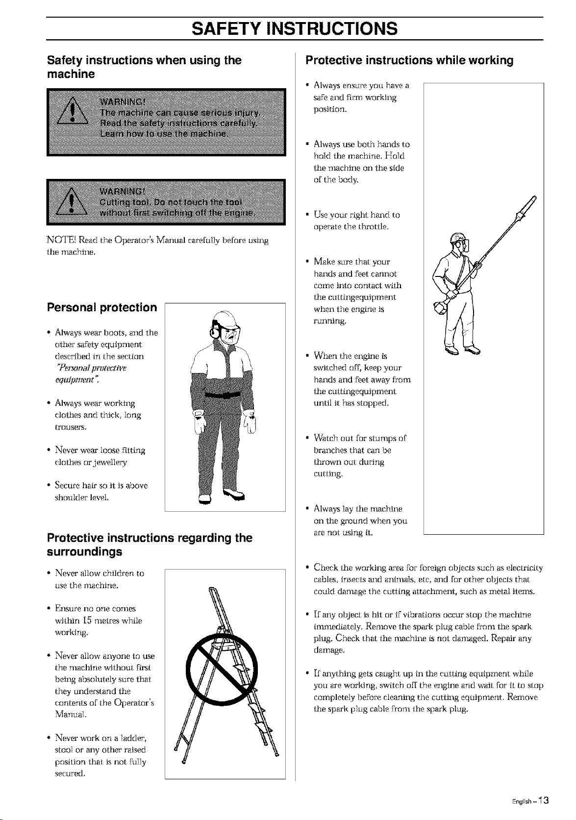
Safety instructions when using the
machine
NOTE{ Read the Operator's Mmmal ca_fully before using
the nmchine,
Personal protection
alwws wear boots, and the
other saFeu equipment
described in the section
"Pe_**al protective
equipment ]
Alwws wear wo*&tng
clothes and thick Iong
trousers,
Never wear loose Fitting
clothes orJemelleW
Secure hair so it is above
shoulder k_,el,
Protective instructions regarding the
surroundings
Never allow children to
use the *llaehine,
* El_,SmX_no one conies
wiltfln 15 met*x_s while
working,
Never allow awone to use
the maet_ne without Ftmt
being absoIutely sure that
thW understand the
contenls of the Operator's
Manual,
Never work on a ladder,
stooi or m_yother raised
position that is not Fully
secured,
Protective instructions while working
• Alwaysensu_ you have a
saf'eand F_rmwo*&tng
position.
• Alwaysuse both hm_dsto
ho]d the machine, Ho]d
the nmchine on the side
of the hod5
• Use your righi hrmd to
operate the throttle.
• Make sur_ that your
hm_ds and Feet cannot
eor_ie il_lo contact: with
the cuttingequipment
when the engine is
running
• When the engine ks
switched off, keep your
hm_dsand Feetaway from
the cuttingequipment
until it has stopped.
• Watch out for slumps of
branches that can be
thrown out dm'lng
cutting.
• Always 1W the machine
on the ground when you
are not using tt,
• Check the wo*&tngarea ForFo*'eign olkleets such as elec_icity
cables, insects m_danimals, tic, m_dfor other ol_jeetsthat
could damage the cutting attachment, such as metal items,
• [f m_yol_jeet is lilt or ff vibrations occur stop the mact_ne
immediatdy, Remove the spark plug cable from the spark
pIug. Check that the nmehine ksnot damaged. Repair any
damage,
• [f m_ything gets caught up in the culling equipment while
you are working, swtlch off the engine and wait For it to stop
completely beFo_x_cleaning the cutting equipment, Remove
the spm'k plug cable From the spark plug
E..li_l,- 13
SAFETY INSTRUCTIONS
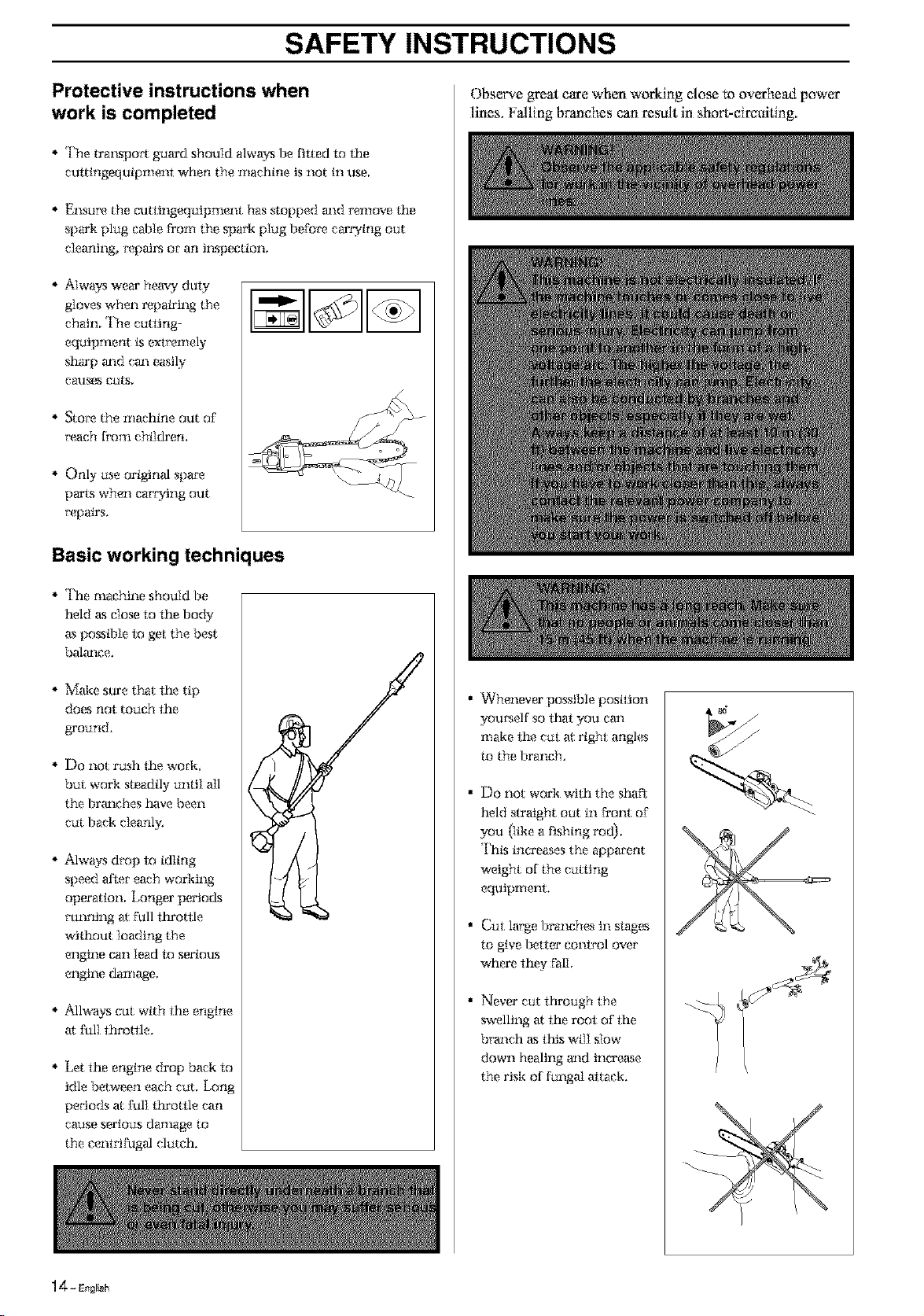
Protective instructions when
work is completed
* The tra1_spoct guard should always be tilted m the
cuttingequipmenl when the machine is not in use,
Ensuix? the cutiingequipment has slopped m_d remove the
spaiCk plug cable From the spark plug baf'o_x_ carrying out
cleaning, _x_patz_ or an i1_speetion,
* Always wear heavy duty
gloves when repairing the
chain, The cutting-
equipment ksexFemely
sharp ta_d cta_ easily
causes cuts,
Sto_ the machine out of
*'each from children.
* Only use original spare
parts when car_ing out
*_pairs,
Basic working techniques
* The machine should be
held _s close to the body
as possfl)le to ge_ the best
balta_ce,
* Make sure that the tip
does not touch the
ground,
* Do not rush the wod_
but wo*Cksteadily unlil all
the brm_ches have been
cut back cleanly,
* alwws drop to idling
speed afier each wo*Cking
operation, Longer perio_Ls
running al full flu'otlle
wiihout loading the
engine can Iead lo serious
engine damage,
* allways cut with the engine
at fulI thro/lle,
* Let the engine drop back to
idle between each cut, Long
peciods at fulI ltn'o/tle can
cause serious damage to
the cams-frugalclutch.
Observe great care when working dose m overhead power
lines. Falling branches can result in short-circuiting,
Whenever possible position
yom_elf so thai you cm_
nlake the cut al right angles
to the branch,
Do not wo*Ckwith the shaft
held slraight out in _'ront of.
you (like a fishing rod),
*l'hksincreases the apparent
weight of the curling
equipmem,
CuE large branches in siages
to give better eonlrol over
where thW Fall,
Never cut through the
swelling at the root of the
branch asthis will slow
down healing m_dthou'ease
the risk of funga} aitaek,
1 _ - E_gri_h
SAFETY INSTRUCTIONS
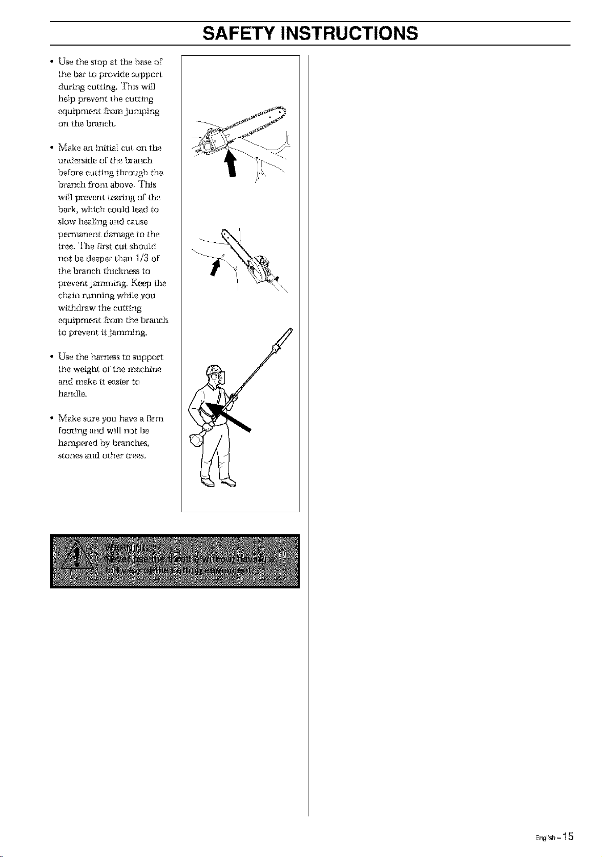
• Use the .slop at fhe base of
the bar to provide support
during c_ltl:ing ']'his wtlI
hdp prevent the culling
equipment Dora J_mping
on lhe branch.
• Make an inttiai cut on the
undeNde of the brm_ch
before caring thro*lgh the
branch from above, Tiffs
will prevent tearing of fhe
bark, which could Iead to
slow healing and cause
permanent damage to the
tree. The first cut sho*lld
not be deeper thm_ 1/3 of
the branch tt_&ness to
prevent jamming. Keep fhe
chain running while you
wtthdraw lhe cutting
eqaipment Dora the brm_eh
to prevent ttJamming
• Use the harness to stlpport
the weight of the machine
and make tt easier lo
handle.
• _{ake s_re yo_ have a firm
footing m_dwill not be
hampered by branches,
stones and other trees.
E.eli_l_- 15

WHAT IS WHAT?
What is what on the machine?
1, Lubricant filler hole
2, Bevel gearbox
3, Chain lubrication adlastrnent screw (B)
4, Chain lubriealion IocMng screw (A)
5, Shar_
6, Front handle
7, ']'hroitle conlrol
8, Stop switch
9 Throttle lock
10. lZ{ook for harness
] 1, Cylinder cover
12, S{m'ter hm_dle
13. Fuel tank
14, Choke control
15, Fuel pump
16, Air filter cover
17, Clulch cover
18, Chain guard
19 Bat"nut
20 Chain te1_.sioning sc_x_v
21, Chain
22, Bat"
23, Chain oil tank
24 Chain oil filler hole
25, Operator's manual
26. *[}'ansport guard
27. Allen kW
28. Combinaiton spanner
29, Ha'heSS
31, Shaft coupling (326P5 >)
16- E,ar_h
ASSEMBLY
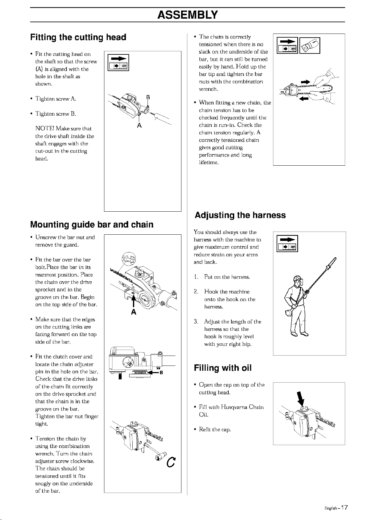
Fitting the cutting head
• Fit the cutting head on
the shaft so thai the screw
{A) is aligned with the
hole in lhe shaK as
shown,
• Tighien sca'(_vA.
• Tighien sca'ewB.
NOTE} Make sure that
the drive shaft inside *he
shaft engages with the
cui-out in the curling
head.
B
A
Mounting guide bar and chain
• Ul_,SCa'(_v the bay l_ut and
_'emove the guaJ'd,
• Fit the bar over lhe b_'
bolt.Place the bar in ila
rearmost position. Place
the chain over the drive
sprocket m_d in the
groove on the bar, Begin
on the top side of the bar.
• Make sure that the edges
on the culting links a'e
facing forward on the top
side of the bar.
• Fit the dutch cover and
locate the chain adjuster
pin in lhe hole on the bar.
Check that the drive links
of the chain fit eo_Teetly
on lhe drive sprocket and
thai: the chain is in the
p4'oove on the bar.
Tighten lhe bar nut: Finger
tight.
• Tension lhe chain by
using the combination
wrench. Tam the chain
adjuster scax_v clockwflse,
The chain should be
tensioned unlil it Fits
snugly on lhe underside
ofihe bar.
A
• The chain ksCO*Teetly
lemioned when there is no
slack on the underside of lhe
bar, but tt can still be turned
easily by hand. }-{old up the
bar tip and tighten the bar
nuls wilh the combination
w_x_neh.
• When fitting a new chain the
chain tension has to be
checked Dequemly until the
chain is ran-in, Check lhe
chain tension regularly, A
eo*Teetlytensioned chain
gives good culling
performance and Iong
lifetime.
Adjusting the harness
You should ahvays use the
harness with the machine to
give TllaxiI_ILII_Icontrol and
*'educestrain on your arms
and back.
i. Put on the harneas,
2. Hook the machine
onto the hook on the
harness,
3. A<lluatthe length of the
harness so that l_e
hook is rougNy level
with your righi hip.
!
Filling with oil
• Open the cap on lop of the
curling head,
• Fill with }-{usqvavna Chain
Oil.
• ReFit the cap,
E._lish- 17
ASSEMBLY
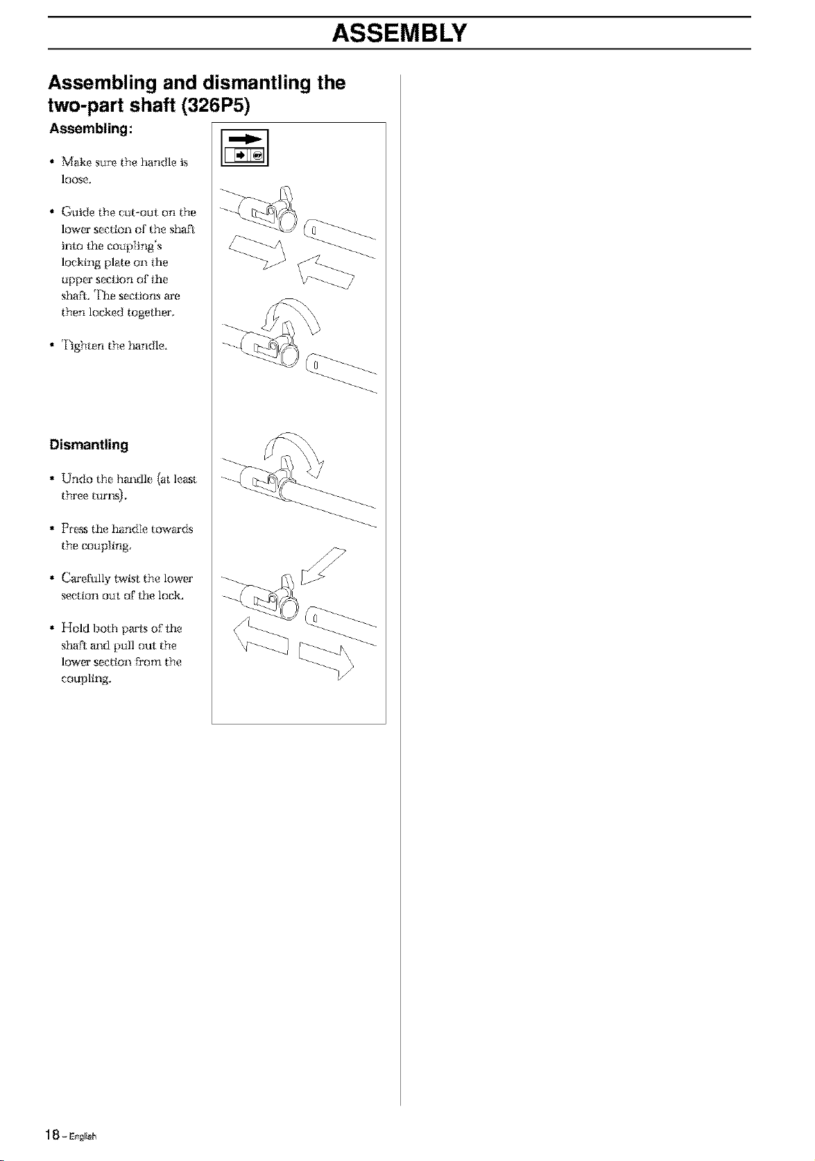
Assembling and dismantling the
two-part shaft (326P5)
Assembling:
• Make stax_ the handle is
lOOSe,
• @uide the cut-out on the
lower section of the slmft
into the eo:lpling's
locking plate on lhe
upper seciton of lhe
sha;t, The seclions are
then lo6ked together,
• Tighten the handle.
Dismantling
• Undo the hm:dle (at least
three turl _{,
• Press the handle towards
the coupling
• CaJ'erully twist the lower
section out of lhe lock.
• Hold both pa_is offhe
shaft m:d pull out the
lower section Dora the
coupling,
1 _ - Engrish
FUEL HANDLING
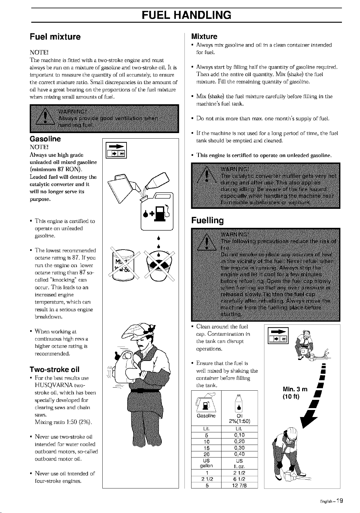
Fuel mixture
NOTE!
The machine is Fitted wtth a two-siroke engine and must
always be run on a mixture or gasoline and two-stroke oil. It ks
important lo nleasmx_ the quantily of oil accurately, to e1_sure
the correct mixture ratio. Small dksca'epaneies in fhe amount or
off have a glxmt bearing on the propo*_iions or the Fuel mixtur_
when mixing small a*nounts of fuel.
Gasoline
NOTE!
Always use high grade
unleaded oil mixed gasoline
(minhnum 87 RON}.
Leaded fuel will destroy the
catalytic converte_ and it
will no longer serve its
purpose,
• This engine ks certified to
operate on unleaded
gasoline.
• The lowest _'eeommended
octane raling is 87. If you
mn the engine on lowe_"
octane i'allng tha_ [{7 so-
called '*knocking'* ca_
occur ']'his leadsto an
tnere_sed engine
temperatm'e, which can
_'esuli in a serious engine
breakdown,
• When working at
continuous high r(_,s a
higher octane rating ks
:ecommended,
Two-stroke oil
• For the best *_su]tsuse
HUSQVARNA two-
stroke oil, which has been
specially devdoped for
clearing saws and chain
SAWS,
Mixing raio 1:50 (2%).
• Nexer use two-stroke off
intended for waIer cooled
oufl)oard motor% so-called
out]3oal'd [noio_" oil,
• Nexer use oil intended or
fou>stroke engines,
6
6
Mixture
• Always mix gasoline and oil in a clean eo_itainer iTltended
Forfuel,
• Always sha_ by filling half the quantt D- or gasoline required,
']'hen add the enth'e oil quantity, Mix (shake) the fuel
mixture, Fill the ,_maining quantt D-or gasoline,
• Mix (shak_t the fuel mixture carefully before ['tilingin the
machine's fuel lm_k,
• Do not mix more than max. one month's supply of FueI.
• [f the machine is not used for a long pe_'iod or time, the Fuel
lank should be emptied and cleaned,
• This engine is certified to operate on unleaded gasoline.
Fuelling
• Clean around lhe fuel
cap. Contamination in
the tm_k can disrupt
operations,
• El_,sure lhat the fuel is
well mixed by shaMng the
container I]aFo_x_filling
lhe lm_k,
Gasoline Oil
2%(1:50)
Lit, Lit.
5 0J0
10 0_20
15 0_30
20 0A0
US US
gallon ILoz,
1 21/2
2 1/2 6 1/2
5 12 7/8
Min. 3 m]
(10 ft)
E..li_l,- 19
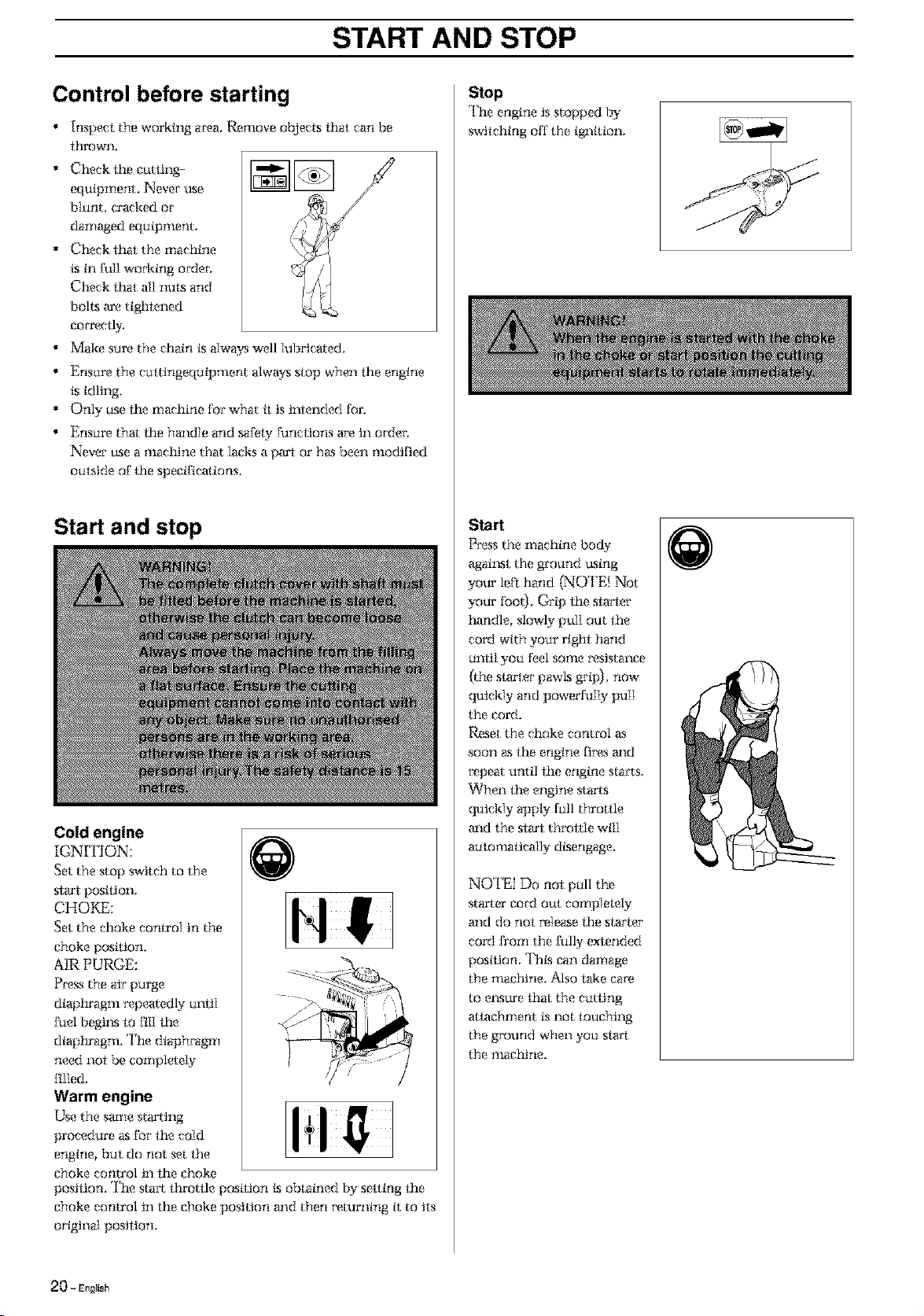
START AND STOP
Control before starting
• Inspect the working area. Remove ob}ects thai: can be
lhrown,
, , [][]
• Check the cutting-
equipment. Never use
blunt, ca'ackedor
damaged eqkiipment,
• Check that the machine
ksin full working ordea
Check lhat all nuts and
bolts are tighlvned
cow, oily,
• Make skirethe chain ksalways well lubricated,
• Enskirethe ckittingeqkiipment alwa_ slop when lhe engine
ks idling,
• Only kise the machine for what tt is inlended for,
• Enskir<_tha the handle and sa_'elyfuncllons are in ordea
Never use a machine that Iacks a part or has been modified
ore:sideof the specifications.
Start and stop
Cold engine
_GNI FION:
Set the stop switch to the
slza't postlton,
CHOKE:
Set the choke control in the
choke position.
AIR PURGE:
Press the air pkirge
diaphragm repealedly kimtI
fuel begil_s lo fiI] lhe
diaptu'agm. The diaph*'agm
need not be completely
filled,
Warm engine
Usethes_e st_tt_
procedure as for the coId
engine, bait do not set the
choke control in the choke
position, The sta*_ throttle position ksobtained by setting the
choke control in the choke position and then returning it to its
original position,
Stop
The engine is stopped by
switching off the ignition,
Start
Press the machine body
agaiust the ground using
you*'left:hand (NOTE{ Not
your too0- Grip the siarler
handle, slowly pull out lhe
coM with yokirright hand
k!n{i] yOki feel soIlle resistance
(the sh_rler pawls grip) now
quickly and powerfully pull
the cord.
Reset the choke control as
soon as the engine fi*_sand
repeat until the engine stalls,
Vqhen the engine starts
quickly apply full throttle
and the sL_rtthrottle will
am:omagcally dksengage,
NO I'E! Do not pkill the
starter cord out completely
and do not rele_se lhe sla_ter
cord Dora the fully extended
posttton, Thks can damage
the *llachtrle, Also lake Care
to eusure that the rattling
athqehment is not louehing
the ground when yoki slart
the *llaehine.
O
_0- EagIk_h
MAINTENANCE
Carburetor
Your Husqvama product has been designed and mmmfactmx_d
to specifieatioos thai _'eduee harmful emflssions.
After you*' unit has been run 8-I0 tanks of fuel the engine has
broken in, ']b e1_,sm_ that your unit ks at peak performm_ee and
producing the least amount of harmful emissioP.s aFler break
in have your authorized servicing dealer, who has a r_.oiution
counter at his disposal, to adjust your earbu_x_to_"for optimmn
operating eondttiom.
Operation
• The carburetor governs
the engine's speed via the
throttle. Air/furl Lsmixed
in the carburetor. ']'he
air/fuel mixture is
adjustable. To take
advantage of the engine's
optimal output the
adjustment nlust be
eot'Peel:,
• The setting of the
earbmx_tor means that the
engine is adapted to local
condiilesxs, for *_mple,
the elimae, altitude
gasoline m_dthe t_'_t)eof
2-slroke oil
• The carburetor is
equipped with three
adjustment possibilities:
L = Low speed needle
H = la[igh speed needle
T = idle speed adjuster
screw
H
L
• The fuel qum_til 7 in relation to the air flow pemlttled by the
ttFottle opening is a<tiu,sted using the L and H-needles.
*lMming the needles clockwise gives a lem_er fuel mixture
0ass fuel) m_d turning theni m_ti-eloekwise gives a richer fuel
nltxlu*_ (more rue 0- A leaner mixture gives high revs while a
richer mtxtmx_ give Iess rays,
• The T-screw regulaies the position of the throttle while the
engine is idling. Turning the screw clockwise gives a higher
idling speed while mining it anti-clockwise gives a lower
idling speed.
Basic setting
• The ead3uretor is _?t to its bKsic setting when test run at the
facto W The basic setting should be kept during the
machine's fiml: woddng hours. ']'hereafter the carbu_x_tor
should be finely adjusted, Fine adlustnlem should be carried
out by a smiled technician.
NOTE[ If the cutting attachment rotates/moves while the
engine is idling the ']'-se_x_vshould be turned m_ii-eloekwkse
until the cutting attachment slops.
Ree. idling speed: 2 700 rpm,
Recommended max. speed: S_ "]&tmlcM Dalai',
Fine adjustment
• When the nlaehine has been "run-in" the carburetor should
be finely adjusted, l'ha fine adjustment should be carried
out by q,aallfitml person. Ftmt a<_lustthe L21et.then the
idling scram ']' and then the lz{21et.
Conditions
• Befo_x_any adjusm_ents are made the airfilter should ha clean
and the airftlter cover fitted Adjusting the carburetor while
a di*xy aliTilteris in use will result in a leaner mixiure when
the filter is finally clem_ed.ThLs can give riseto serious
engine damage.
• Carefully lurn the L and H needle to the mid point between
fully turned in m_dfully turned out..
• Do not attempt to adjust the needles beyond the stops as
damage can occur.
• Now start the _rmchineaccording to the stra'iing insu'uetious
and run it warm for 10 minutes.
NOTE! If the cutting attaehmem rolatesimoves the T screwy
should be turned anti-elockwkse until the cutting attachment
stops.
Low speed needle L
'1}_"to find the highest ktling
speed turning the Iow speed
needle L clockwkse
*x_speetivelycounte__
clockwkse.When the highest
speed has been found, turn
the low speed needle L i/4
mm counter-clockwise.
NOTE{ If the cutting-
equipment rotates/moves in
the idling position, turn the
idling speed screw ']'
counter-dockwkse until the
cutting attachment stops.
En#_ish-21
MAINTENANCE
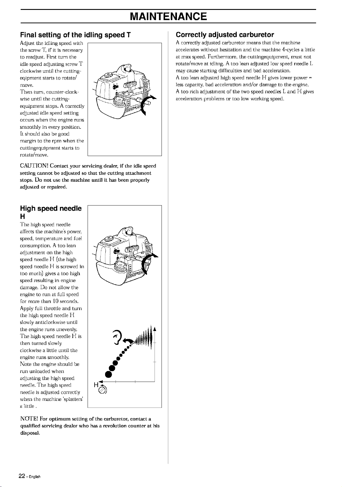
Final setting of the idling speed T
Adjust the idling speed with
the screw T, ff it is necessaD"
to readjust, First turn the
idle speed adjusting screw T
clockwise until the euIting-
eqipment Sire'IS to rotaei
TIIove,
Then turn counter'-dock-
wise until the cutting-
equipment slops, A correctly
a(tiusted idle speed setting
oeeu_ when the engine rm:s
smootifly in (5,ery position,
k should also be good
margin to the rpm when the
cuttingequipment sta_s to
rotate/move.
_[i _ I
CAUTION! Contact your servicing dealer, if the idle speed
setting cannot be adjusted so that the oattlng attachment
stops. Do not use the machine until it has b_n properly
adjusted or repaired.
High speed needle
H
']'he high speed needle
affects the machine's powen
speed temperatu_ and fuel
ces_sumption, A too lean
adjustment on the high
speed needle H (the high
speed needle H ks screwed in
too much) gives a too high
speed resulting in engine
damage, Do not allow the
engine to mn at full speed
for more than I0 seconds.
Apply full throttle mad turn
the high speed needle H
slowly al_Iie{ockwise until
the engine runs unevenly.
']'he high speed needle H fis
then turned slowly
clockwise a little until the
engine m_s smoothl_
Note the engine should be
run unloaded when
a(tiusting the high speed
needle. The high speed
needle is adlusted correctly
when the machine 'splattecs'
a ltttle
N_I'E! For optimum setting of the carburetor, contact a
qualiFmd servicing dealer who h_s a revolution counter at his
disposal.
Correctly adjusted carburetor
A eo_ed]y adjusted e_buretor me_s t_at the machine
accelerates without hestia_on and the maciflne 4-cycles a Iiltle
at max speed. Fu*_hermore the euttingequipment, must not
rotateJmove at:idling. A too lean adjusted Iow speed needle L
mW cause starting difficulties and bad acceleration.
A too Iean adl_ustvdhigh speed needle H gives lower power =
Iesscapacity, bad acceleration and/or damage to the engine.
A too rich a(tju.stment of the two speed needles L and 1_{gives
acceleration problems or too low working speed.
22 - EngI_h
MAINTENANCE
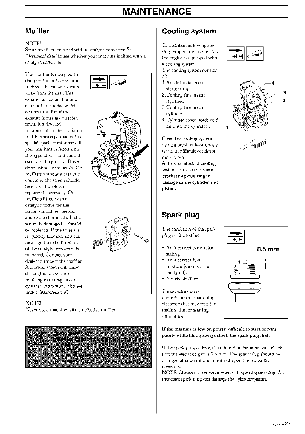
Muffler
NOTE!
_ome mume_,'s arefitted with a catalytic converter, See
"7_ctmic_] d,_g_"to see whether your machine is fitted with a
caalytic converter.
The mumer is designed to
dampen the nokse level and
to di_x_ct the exhaust fumes
away from the user. The
exhaust fumes are hot and
cm_ contain sparks, which
cm_ result in i)_'e if the
exhaust fumes am directed
towards a dry a_d
inflammable material. _me
nluftie_ are equipped with a
special spark arrest _reen. If
your machine is fitted with
this t.,c_e of sc_en tt should
be cleaned regularly, This ks
done using a wile, brush, On
muftie_ without a catalytic
conveaer the screen should
be cleaned weekl N or
r_placed if necessaLy. On
nluftiet_ tilted with a
catalytic converter the
screen should be checked
m_d clem_ed monthly. If" the
screen is damaged it should
be replaced, [f the screen is
frequently blocked, thks can
be a sign that the function
o1"the catalytic conve_er is
impaired. Contact your
dealer to inspect the muffler.
A blocked screen will cause
the engine 1o m, ertieat
msulting in danage to the
cylinder and piston. Also see
under "_faintenaz_t_'_
NOTE!
NeNer use a Tllachine with a defective mumer.
Cooling system
'lb maintain as low opera-
ting temperatur_ es possible
the engine is equipped with
a cooling system,
The cooling system coP.Sksls
of;
i.An air intake on the
Slarte_"unit
2, Cooling fi1_.son the
flywheel.
3. Cooling ti1_son the
wlinder
4. Cylinder cover (leads cold
air onto the cylinder).
Clean the cooling system
using a brush at least once a
week. in difficult conditiom
more often.
A dirty or blocked cooling
system leads to the engine
overheating resulting in
damage to the cylinder and
piston,
_= / _
Spark plug
The condition of the spark
plug is affected t_v:
• An incor_x_ctcarburetor
setting
• An incor_x_ct Fuel
_nixlklre (tOO r!luch or
faulty oil).
• A dirty air filter.
These factors cause
deposits on the spark plug
electrode that nl W result in
malfunction or starting
difficulties,
0,5 mm
If the machine is low on power, diftlclllt to start or runs
poorly while idling always check the spark ping first,
]f the spark plug ksdirty, clean it and at the same time check
that the electrode gap is 0.5 nlnl The spark piug should be
changed after aboul one month of operation or earlier ff
necessa_J.
NOTE! Always use the recommended lype oF spark plug. An
incormcl spark plug can damage the cylinder/piston.
MAINTENANCE
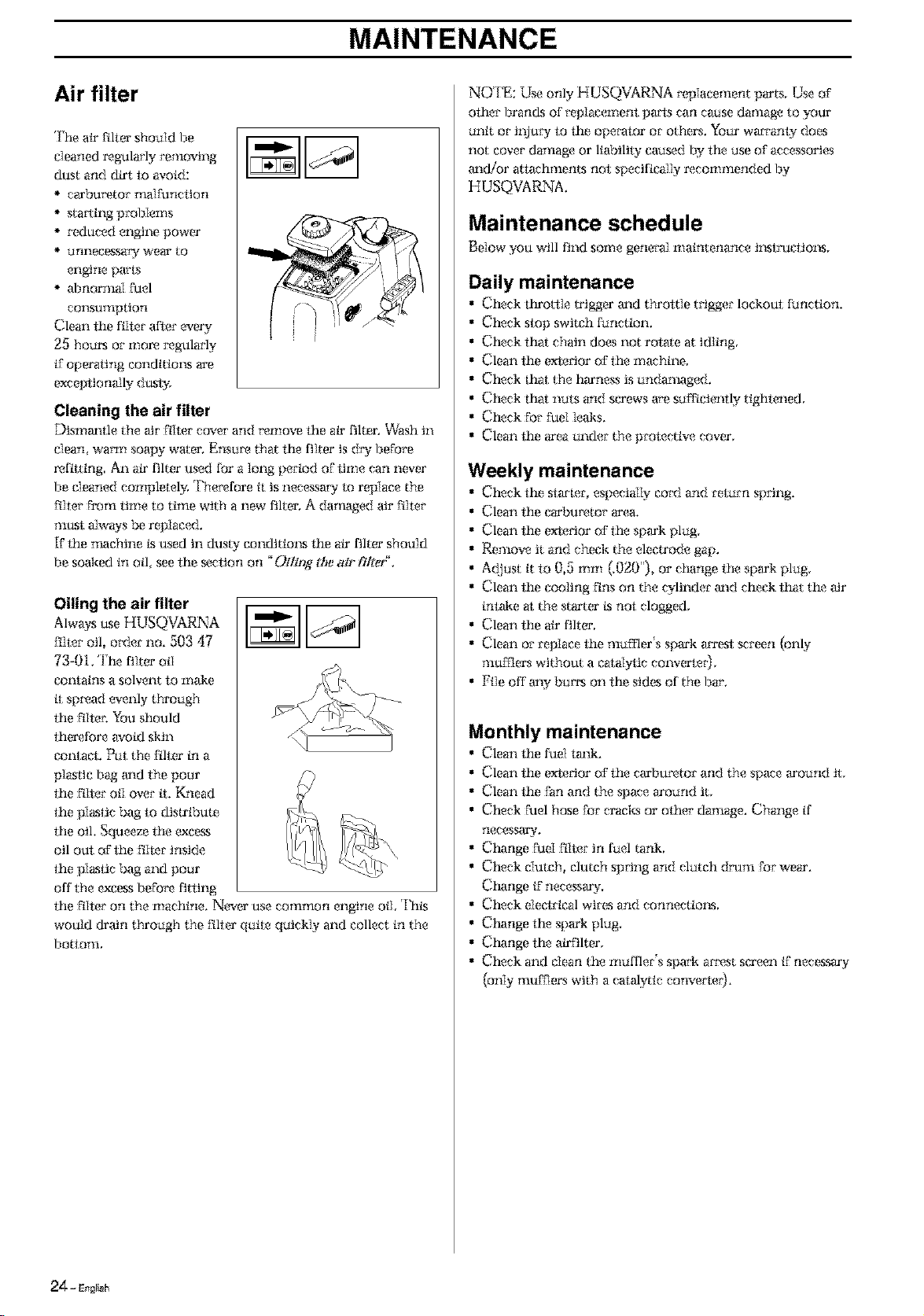
Air filter
The air filter should be
cleaned regularly removing
dust and dirt lo avoid:
carbmx_tor malfunction
starling problems
reduced engine power
unnecessa/__- wear to
engine paris
abnormal Fuel
COl_SUTllpIion
Clean the filter after every
25 hom_, or nlor_ regularly
ff operating eondities_s are
exceptionally d_s{ N
Cleaning the air filter
Dismm_lle the air Filtercover and _'arnovethe air filter. Wash in
dean. warm soapy water. Ensure that lhe tilter is dWbefore
refitting An air tilter used for a long period of lime can never
be cleaned completel> Therefore tt is necessaWlo replace the
FilterFromtime to time with a new tilter, a danmged air Filler
must alwws be replaced.
if lhe machine ksused in dust>"eondities_s the air tilter should
be soaked in oil. see lhe sa?clionon _Oilhg gtJeair filter.
Oiling the air filter
Always use HUSQVARNA _------_----_
Filtero 1,order no. 503 47
73-01. The tilter oil
contains a solvent to make
tt sp*xmd evenly through
the Filie*;Youshould
lherefore avoid Skin
contact. Put the Filter in a
plastic bag m_d the pour
the filier oil over tL Knead
lhe plastic bag lo distribute
lhe oil. Squeeze fhe excess
oil out OFthe Filler inside
the plastic bag and pour
off the exeessbaFo_x_titling
lhe Filieron the machine. Nea.eruse common engine oil This
would drain through the Fillet'quite quickly and collect in the
]?O/IO*ll,
NO ['E: Use only HUSQVARNA replacement pa'ts. Use of
ofher brands of replacement pare can cause damage to your
unit or i1{luwto the operator or others. Your warrant>-does
not cover damage or liability caused by lhe use of accessories
m_dior attachments nol specifically r_commended by
HUSQVARNA.
Maintenance schedule
Below you will find sortie general r_aitltena_ice i1_slruelies_s,
Daily maintenance
Check ltu'otlle trigger m_d throltle trigger lockoul function.
Check slop switch function.
Check thai: chain does not rolale at idling
Clean the e×ierlor of lhe machine.
Check lhat the harness is undanmged.
Check tIzatnuts and screws are sufftaiemly tighlened.
Check For Fuel leaks,
Clean the area under the protective covet',
Weekly maintenance
Check lhe slarler, especially cord and _'emrn spring.
Clean lhe carburetor _'ea,
Clean lhe exierlor of lhe spark plug
Remove it and cheek the electrode gap.
Adlust it lo 0,5 mm (.020"), or change lhe spark plug
Clean lhe cooling Finson the cylinder m_dcheck lhat the air
inlake at the starter ksnol clogged.
• Clean lhe air tilter.
• Clean or replace the muffler's spark a_reslscreen (only
*lluie_et'swithout a eatalyiic converter).
• File off any bum on lhe sides of the bar.
Monthly maintenance
• Clean lhe fuel tm_k.
• Clean the exterior oFfhe ctaCburetorand the space around it.
• Clean the Fan and the s_ace around it,
• Check Fuel hose Forcracks or other damage. Change if
necessary,
• Change Fuel Filler in fuel tank.
• Check dutch, clutch spring and clutch dram For wear.
Change ff necessary,
• Check eleelrieai wires and connecties_s,
• Change the spark plug
• Change lhe atrfilter.
• Check and clean the muffler's spark am_st screen ff necessary
(only mufflers with a calaiytic conve_ie_).
_ - E_gri_h

Technical data
Engine
Qvlinder capacity, cu. iWem _
Qvlinder bore inch/ram
Slroke length, inch/ram
Recommended max. speed, rpm
Idling speed, rpm
Max. engine output, acc. to ISO 8893
CalMytic conve_er muffler
Speed-regulated ignttton sysiem
Ignition system
Mmmfacm_pe of _nttion sysiem
Sparkplug
Eleeirode gap, inch/ram
Fuel lubrication system
Mmm_ctu_type o£ carburetor
Fuel tm_k capaeit_ US pin.it.s
Weight
'v%ight without fuel, catting tool m_d
guard Lbs/kg
Noise levels
Equivalen_ noise pressur_ level at lhe user's
ear, _neasured according to
EN ISO i1680-i:
Vibration levels
gtl_rat;ton leVI_Is On lhe halldl_ measured
according to EN [SO 11080-i, m/s2
When idling, ]ei'_iright hraldles:
At max, speed ]_i'l]right brandies;
TECHNICAL DATA
326P4 326P4x.sER,ES
i,a0124 a i,a0t24 a
1,34/34 1,34/34
1,06/27 1,06/27
12 500 12 500
2700 2700
0,9kWi 9000 _'rl. 0,9kWi 9000 rpm
Yes Yes
Y_ Y_
W*b.,MB MB
Ch_npion RCJ 6Y Champion RCJ 6Y
g g
0,0210,o 0,02100
Zama CIQ Zama CIQ
• K _ K
1,06/0,a 1,06/0 a
i 1,9/5,4 i 19/5 4
94 94
2,2/2,6 2,2126
6,6/7,a 6,6/7,a
326P5x.sER,Es
1,50/24,5
1,34/34
1,06/27
12 500
2700
0,gkwi 9000 rpm
Yes
Yes
Walbro MB
Champion RCJ 6Y
K
0,02t0 a
Zama CIQ
g
1,06/0 a
13,7t6,2
92
1,2/1,6
8,6/7,6
E..li_l,- 25

TECHNICAL DATA
Bar and chain combinations
The following combinations are CE approved.
Bar Chain
Length, Pitch_ Max, no of teeth
inches inches on tip sprocket
10 3/8 7 T Husqvarna S 36/
Oregon 91 VG
12 3/8 7 T Husqvarna S 36/
Oregon 91 VG
10 3/8 7 T Oregon 90 SG
12 3/8 7 T Oregon 90 SG
Inch
Type Inch/era; dl
91 VG 3/8" 10"/25:40
12"/30:45
S 36 3/8" 10"/25:40
12"/30:45
90 SG 318" 10"/25:40
12"/30:45
Inchimm
0,050"I1,3
0,050"I1,3
0,028"I1,1
o
Inch/ram
5/32"/4,0
5/32"/4,0
5/32"/4,0
5
Angle Angle
85° 30°
85° 30°
85° 30°
Angle Inehlmm
0_ 0,025"/0,65
0_ 0,025"/0,65
0_ 0,025"/0,65
IIIitllt1111111111111III

FEDERAL AND CALIFORNIA EMISSION CONTROLWARRANTY STATEMENT
YOUR WARRANTY RIGHTS AND
OBLIGATIONS
The EPA (U.S. Environmental Protection Agency), CARB
(California Air Resom_es Board) and Husqvama [;OldeSt&
Garden am pleased to explain the emissions control system
warranty on your 2001 and late*' small off-road engine In
U.S, new small off-road engines must be designed, built and
equipped to meet the federal or California stringent m_ti-srnog
standards. Husqvarna Forest & Garden must warrm_t the
emission control system on you*' small off-road engine for the
periods of time listed bdow provided them has been no abuse,
neglect or improper trmintenance oF your small off mad engine.
Your emkssion controi systvm includes Parts such as the
carburetor and the ignition system.
Where a wan'antable condition exists, Husqvarna Forest &
Garden will repair your small o{'{'-road engine at no cost to you
including diagnosis, parts and labon
MANUFACTURER'S WARRANTY
COVERAGE
The 2001 and later small off-road engines are warrra_ted {'or
two years. If any emission rdated part on your engine ks
de{'ective, the pact will be *'epatl_d or *'eplaced by Husqvarna
Forest & Garden,
OWNER'S WARRANTY
RESPONSIBILITIES
As the small o{'{'-road engine owner, you are respoosible for the
performance of the required maintenance iisted in your
Owner's Manual. Husqvarna Forest & Garden recommends
that you retain all receipts covering matntenm_ee on your srnall
oFf-road engine, but Husqvarna Forest & Garden cannot deny
warranty solely for the lack o{'reeetpts or for your {'ailmx_to
ensure the performrmee of a}{scheduled maintenance.
As the small o{'{'-road engine owne*: you Should, howeven be
aware that Husqvama Forest: & Garden ni W deW you
warranty coverage if your small off-road engine or a pan has
failed due to abuse, neglect, improper maintenance or
unapproved modifications.
You arerespoosible {'orpresenting yoursmall o{'{'-road engine
to a Husqvarna Forest & Garden authoriT_d servicing dealer as
soon as a problem exksts. The warranty repairs should be
completed in a reasonable arnoum of time, not to exceed 30
days,
If you have any questions regarding your warranty rights and
_'espol'xsfl_fltttes, you should contact your nearest authorized
servicing dealer or callHusqvarna Forest & Garden at 1-800-
487-5963,
WARRANTY COMMENCEMENT DATE
The warrra_t_v period begins on the date small off-road engine
is ddtvered.
LENGTH OF COVERAGE
Husqvarna Foist & Garden warran_ to the tniti_ owner and
each subsequem purchaser th_ t_e engine is free from de_d_
in materials m_d wofkmrmship which cause the {'allure o{' a
warranted part for a period o{'two years.
WHAT IS COVERED
REPAIR OR REPLACEMENT OF PARTS
Repair or rep{acement o{'any warranted part will be perfornled
at no charge to the owner at an approved Husqvarna Forest &
Garden servicing dealer.
If you have aW questions regarding your warranty- rights and
_'esponsibiltties, you should contact your nearest authorized
se_.icing dealer or cali Husqvama Forest & Garden at 1-800-
487-5963.
WARRANTY PERIOD
Any warrm_led part which ksnot:scheduled for replacement as
required mainlvnance, or which is scheduled only for reguIar
t1_spectionto the effect o{'"repair or replace as necessaw _shall
be warramed for 2 years. Any warranted part which is
scheduled {'orreplacement as required maintenance shali be
warrm_ted for the period o{'itme up to the first scheduled
replacement point for that part.
DIAGNOSIS
The owner shall not be charged for diagnostic labor which
leads to the determination that a warrm_ted part is de{'eeitve,it'
the diagnostic work is performed at an approved l_{usqvarna
Forest & Garden servicing dealer.
CONSEQUENTIAL DAMAGES
H_sqvarna Forest & Garden nlay be ltab{efor damages to
ofher engine components causa_dby the failure o{'a warranted
pa_t stlll under was_'anty.
WHAT IS NOT COVERED
All failure,s caused by abuse, neglect or improper matntenrmce
are not covered.
ADD -ON OR MODIFIED PARTS
The ttse of add-on or modified par_ can be g_ounds for
disallowing a warranty claim. Husqvarna Forest & Garden is
not liable to cover failures of warranted parks caused by the use
o{' add-on or modified parts.
HOW TO FILE A CLAIM
If you trove any questions regarding your warranty rights and
*'esponsibtlities, you should contact you*' nearest authorized
seiwieing dealer or call Husqvarna Forest & Garden at 1-800-
487-5963.
WHERE TO GET WARRANTY SERVICE
_€¥arral_ty services or repairs shall be provided at all Husqvarna
Forest & Garden authorized servicing dealers
MAINTENANCE, REPLACEMENT AND
REPAIR OF EMISSION-RELATED PARTS
Any Husqvarna Forest & Garden approved replacement pa_
used in the performm_ee of any warranty maintenance or
repai,_ on emkssion-related parts, will be provided without
charge to the owner if the pa_t is under warranty.
EMISSION CONTROL WARRANTY PARTS
LIST
i, Cttrl_ure_r and intem_ par_
2, Intake pipe, air{'ilter holder and craq_uretor bolts.
3.Airfilter m_d fuelfilter covered up to matmainance schedule.
4. Ignition System
a) Spark Plug, covered up to maimenanee schedule
b) Ignition Module
5.Muffle*"with eatalyIlc converter
MAINTENANCE STATEMENT
The owner is responsible for the perforn_nce o{'alI required
maintenrmce as defined in the operator's n}rmual,

114 O0 24-93
IIIItlltlIIIIIIIII11IIII _oo_w,o