Owner's Manual
10 Horse Power
CHIPPER-SHREDDER
Model No.
247.775890
I
I
E
CAUTION: Before using this product,
read this manual and follow all Safety
Rules and Operating Instructions.
Sears, Roebuck and Co., Hoffman Estates, IL 60179, U.S.A.
Printed in U.S.A. 770-081gA
Content Page Content Page
Warranty information 2 Service & Adjustment 15
Safe Operation Practices 3 Off-Season Storage 18
Assembly 5 Trouble-Shooting 19
Operation 8 Parts List 20
Maintenance 12
One-Year Warranty on Craftsman Chipper-Shredder
For one year from the date ofpurchase, when this Craftsman chipper-shredder ismaintained, lubricated, and
tuned up according tothe operating and maintenance instructionsinthe operator's manual, Sears willrepair, free
ofcharge, any defect in material or workmanship.
This warranty excludes the blades, chipper blades, flails,air cleaners, spark plugs, catcher bags and tires which
are expendable parts and become worn during normal use.
Ifthis chipper-shredder isused for commercial or rental purposes, this warranty applies for only30 days from the
date ofpurchase.
WARRANTY SERVICE iS AVAILABLE BY CONTACTING THE NEAREST SEARS SERVICE CENTER IN THE
UNITED STATES. THIS WARRANTY APPLIES ONLY WHILE THIS PRODUCT IS IN USE IN THE UNITED
STATES.
This warranty gives you specificlegal rights and you may also have other rightswhichvary from state to,state.
Sears, Roebuck and Co., D/817WA, Hoffman Estates, IL 60179
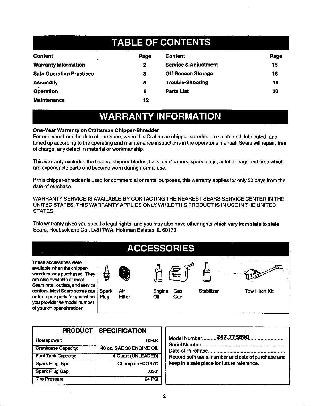
Theseaccessorieswere
availablewhenthechipper-
shredderwaspurchesed.They
arealso availableat most
Searsretailoutlets,andservice
centers.MostSeamstorescan
orderrepairpartsfor youwhen
youprovidethemodelnumber
ofyourchipper-shredder.
Spark Air Engine Gas Stabilizer
Plug Filter Oil Can
Tow HitchKit
PRODUCT SPECIFICATION
Horsepower:. 10H.R
CrankcaseCapacity: 40 oz. SAE 30 ENGINE OIL
FuelTankCapacity:. 4 Quart (UNLEADED)
SparkPlugType ChampionRC14YC
SparkPlugGap .030"
Tire Pressure 24 PSI
Model Number.......... 24,,.7',,.,.'_',.58,9,0,........................
Serial Number...........................................................
Date of Pumhasa ......................................................
Record bothsedal number and date ofpurchase and
keep in a safe place for future reference.
2
Thissymbolpointsoutimportantsafetyinstructionswhich,ifnotfollowed,couldendangertheper-
sonalsafetyand/or propertyofyourselfand others. Read and follow all instructionsinthis manual before
attemptingto operate yourchippershredder. Failureto complywiththese instructionsmay resultin per-
sonal injury.When you see this symbol--heed its warning.
I
Yourchipper-shredderwas built tobe operated according to the rules for safe operation in
DANGER: this manual. Aswith anytype of powerequipment, carelessnessor error on the partof theoper-
ator can resultinserious injury.If you violate any of these rules, you may cause serious
injury to yourself or others.
,_ WARNING: The Engine Exhaust from this product contains chemicals knownto the State of Califomia
to cause cancer, birth defects or other reproductive harm.
GENERALOPERATION
Read this owner's guide carefully in itsentirety before
attempting toassemble this machine. Read,
understand, and follow all instructionson the machine
and in the manual(s) before operation. Be completely
familiar with the controls and the proper use of the
machine before operating it. Keep this manual in a safe
place for future and regular reference and for ordering
replacement pads.
Your chipper-shredder is a powerful tool, not a
plaything. Therefore, exercise extreme caution at air
times. Your unit has been designed to perform two
jobs; to chip and shred vegetation found in a normal
yard. Do notuse it for any other purpose.
• Never allow children under age 16 to operate the unit.
Children 16 years and older should only operate the
unit under close parental supervision. Only responsible
individuals who are familiar withthese rules ofsafe
operation should be allowed to use your unit,
• Keep the area of operation clear ofall persons,
particularly small children and pets. Stop the engine
when they are in the vicinityof the unit. Keep work area
clean and clear of branches or obstacles which could
cause you tostumble or fall.
• When feeding matedal intothis equipment, be
extremely careful that pieces of metal, rocks, bottles,
cans or other foreign objects are notincluded.
Personal injuryor damage tothe machine could result.
Always wear safety glasses or s_oty goggles, dudng
operation and while performing =anadjustment or
repair,to protect eyes fromforeign objects that may be
thrown from the machine.
• Wear sturdy, rough-soled work shoes and close fitting
slacks and shirt.Shirt and slacks that cover the arms
and legs and steel-toed shoes are recommended. Do
notwear loose fitting clothes or jewelry and secure hair
so it isabove shoulder length. They can be caught in
moving parts. Never operate a unit in bars feet,
sandals or sneakers. Wear gloves when feeding
material inthe ohippel_chute or shredder hopper.
• Never place your hands, feet, or any part of your body
intothe shredder hopper, chipper chute, discharge
3
opening, or near any moving part while the engine is
running. Keep clear ofthe discharge opening at all
times. If itbecomes necessary topush material intothe
chipper chute or shredder hopper, use a small
diameter stick, NOT YOUR HANDS.
• If it isnecessary for any reason to unclog the feed
intake or discharge openings orto inspect or repair any
part of the machine where a moving part can come in
contact with yourbody or clothing, stopthe machine,
allow itto cool, disconnect the spark plug wire fromthe
spark plug and move it away fromthe spark plug
before attempting to unclog, inspect or repair.
Do not operate unitwhile under the influence ofalcohol
or drugs.
The machine should only be operated on a level
surface. Never operate your uniton a slippery, wet,
muddy or icy surface. Keep your work area clean and
clear ofbranches or obstacles which could cause you
to stumble and fall. Do notoverreach. Maintaining
preper footing and balance isessential topreventing
accidents.
• Do not allow.an accumu!a_on of prpc_,sed matedal to
build upin the discharge ares.as this willprevent
proper discharge and can result in kick-beck from the
chipper chute.
• Keep your face and body pack from chipper chute to
avoid accidental bounce pack of any mstadel.
• Do not transport machine while engine is running.
• Ifthe cutting mechanism strikee aforeign object or if
your machine should start making an unusual noise or
vibration, immediately stop the engine and allow the
machine to come to a complete stop. Disconnect the
spark plug wire and move itaway fromthe spark plug.
Take the followingsteps.
a. Inspact for damage.
b. Repair or replace any damaged parts.
c. Check forany loose parts and tightento assure
continued safe operation.
• Never attempt to attach or remove catcher bag when
engine isrunning. Shut the engine off and waitfor the
impeller tocome to a complete stop. The impeller
continues to rotate fora few seconds after the engine is
shutoff.Neverplaceanypartofthebodyinthe
impeller area untilyou are sure the impeller has
stopped rotating.
• Muffler and engine become hot and can cause a bum.
Do not touch.
• Do not allow leaves or other debris to build-up on
engine's muffler.The debds could ignite and cause a
fire.
• Do notattempt to shred or chip material larger than
° specified inthis manual. Personal injuryor damage to
the machine could result.
• Do notoperate engine if air cleaner or cover over
carburetor air-intake is removed, except for
adjustment. Removal ofsuch parts could create a tim
hazard.
• Only use acoessodes approved forthis machine by the
manufacturer. Read, understand, and follow all
instructions provided with the approved accessory.
• If situations occurwhich are not covered by this
manual, use care and good judgment. Contact your
dealer for assistance.
• Keep discharge chute deflector, chipper chute flap,
and all other guards and safety devices in place and
operating properly.
• Only operate unitin good daylight. Do not operate unit
at night or in dark areas where your vision may be
impaired.
CHILDREN
Tragic accidents can occur ifthe operator is not alert to the
presence of small children. Children are often attracted to
the chipper-shredder and the chipping and shredding
activity. Never assume that children will remain where you
last saw them.
• Keep children out of the work area and under the
watchful eye of a responsible adult other than the
operator.
• Be alert and tum the unitoff if a child enters the aree.
• Never allow children under the age of 16 to operate the
chipper-shredder.
SERVICE
Use extreme cam in handling gasoline and other fuels.
They are extremely flammable and the vapors are
explosive.
a. Store fuel and oil in approved containers, away
from heat and open flame, and out of the reach of
children. Check and add fuel before starting the
engine. Never remove gas cap or add fuel while
the engine is running. Allow engine to cool at
least two minutes before refueling.
b. Replace gasoline cap securely and wipe off anl
spilled gasoline before starting the engine as it
may cause a fire or explosion.
c. Extinguish all cigarettes, cigars, pipes and other
soumes of ignition.
d. Never refuel unit indoors because flammable
vapors will accumulate inthe area.
e. Never store the machine orfu_l cS"ntalnerinside
where there isan open flame or spark such as a_ -....
gas hot water heater, space heater, clothes dryer
or furnace.
• Never run your machine in an enclosed area as the
exhaust from the engine contains carbon monoxide,
which is an odorless, tasteless and deadly poisonous
gas.
• To reduce fire hazard, keep engine and muffler free of
leaves, grass, and other debds build-up. Clean up fuel
and oil spillage. Allow unitto cool at least 5 minutes
before storing.
• Before cleaning, repaidng, or inspecting, make certain
the impeller and all moving parts have stopped.
Disconnect the spark plug wire and keep wire away
from spark plug to prevent accidental starting. Do not
useflammable solutionsto clean airfilter.
• Check the blade and engine mountingscrews at
frequent intervals for proper tightness. Also visually
inspectblades for wear and/or damage (e.g., bent,
cracked). Replace with blades which meet original
equipment specifications.
• Keep all nuts, bolts, and screws tight to be sure the
equipment isin safe workingcondition.
Never tamper with safety devices. Check their proper
operation regulady.
After strikinga foreign object, immediately stop the
engine, disconnect the spark plugwire from the spark
plug, and thoroughly inspect the unitforany damage.
Repair damage before starting and operating unit.
• Do not alter or tamper with the engine's governor
setting.The governor controlsthe maximum safe
operating speed ofthe engine.. Ov_r-spmedingthe
engine isdangerous and willcause damage to the
engine and to other moving parts ofthe machine.
YOUR RESPONSIBILITY
Rastdct the use of this power machine to
persons who road, understand and follow the
warnings and instructions In this manual and on
the machine.
SAVE THESE INSTRUCTIONS FOR FUTURE REFERENCE
This unitis equipped with an internal combustion engine and should not be used on or near any unimproved forest-
covered, brush.covered or grass-covered land unless the engine's exhaust system is equipped with a spark arreeter
meeting applicable local or state laws (if any). If a spark arrester isused, it should be maintained in effective working
order by the operator.
In the State ofCalifornia the above is required by law (Section 4442 of the California Public Resources Code). Other
states may have similar laws. Federal laws apply on federal lands. A spark arrester for the muffler is evallable through
your nearest Sears Authorized Service Center (See the REPAIR PARTS section of this manual.)
I Rear
2 Bottles
of OII
Hopper"
Chipper
Chute
Discharge Chute
* Thehopperis packed
in_e topInsertIn
yourchipper-shredder
carton.
Figure I
:hlp Bag
Spark Plug Wire
Figure 2
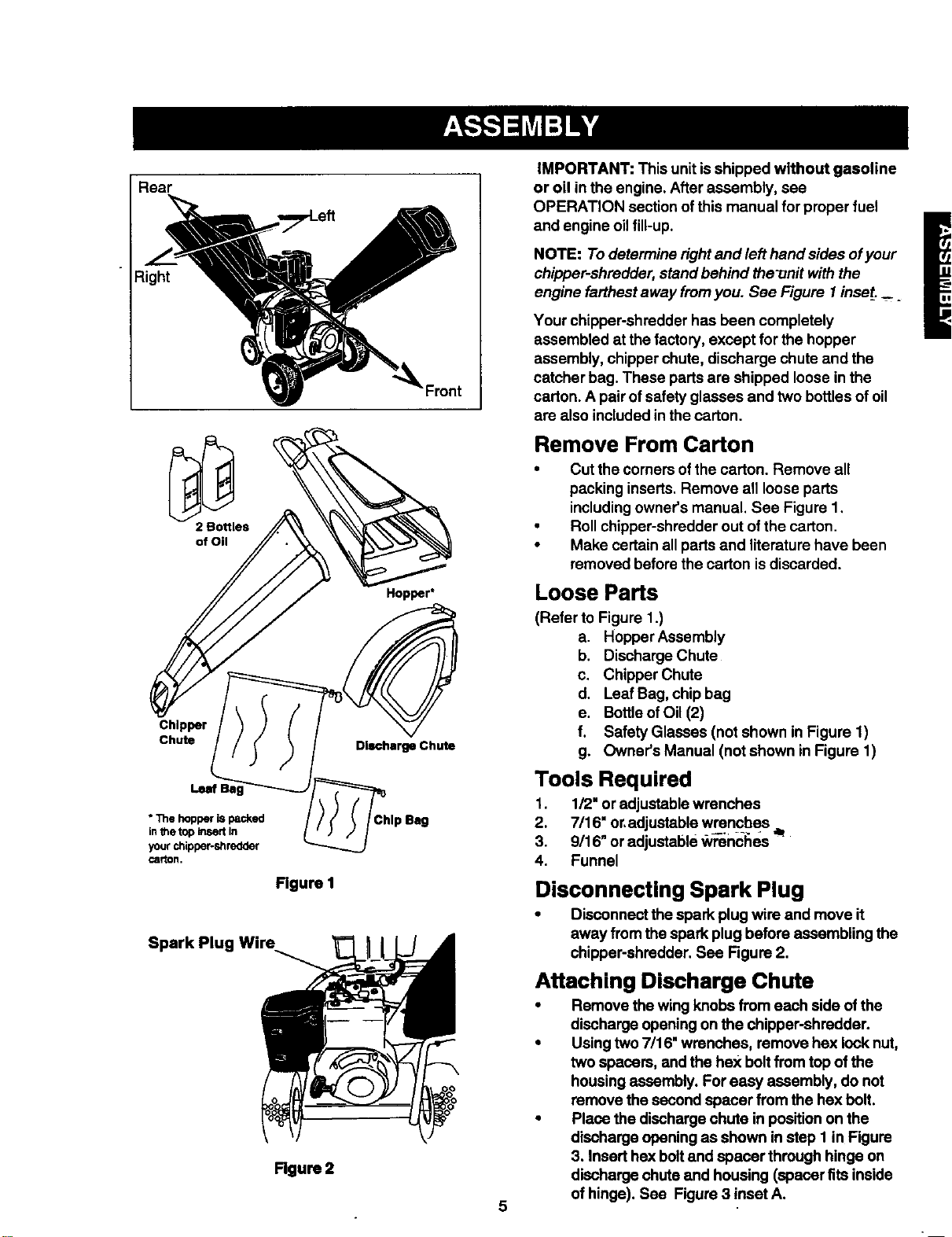
IMPORTANT: This unitis shipped without gasoline
or oil in the engine. After assembly, see
OPERATION section ofthis manual for proper fuel
and engine oil fill-up.
NOTE: To determine rightand left hand sides ofyour
chipper-shredder, stand behind the-onit with the
engine farthest away fromyou. See Figure I inset. _
Your chipper-shredder has been completely
assembled at the factory, except for the hopper
assembly, chipperchute, discharge chute and the
catcher bag. These parts are shipped loose in the
carton. A pair of safety glasses and two bottles of oil
are also included in the carton.
Remove From Carton
• Cut the comers ofthe carton. Remove all
packing inserts. Remove all loose parts
includingowner's manual. See Figure 1,
• Roll chipper-shredder out ofthe carton.
• Make certainall parts and literature have been
removed before the carton is discarded.
Loose Parts
(Refer to Figure 1.)
a. HopperAssembly
b. Discharge Chute
c. Chipper Chute
d. Leaf Bag, chip bag
e. BottleofOil (2)
f. Safety Glasses (not shown in Figure 1)
g. Owner's Manual (not shown in Figure 1)
Tools Required
1. 1/2" or adjustable wrenches
2. 7/16" or,adjustable wrencbes
3. 9/16_ oradjustable _ncl_es "_
4. Funnel
Disconnecting Spark Plug
• Disconnectthe spark plug wire and move it
away from thespark plug before assembling the
chippar-shredder. See Figure 2.
Attaching Discharge Chute
• Remove thewing knobs from each side ofthe
discharge opening on the chipper-shredder.
• Using two 7/16" wrenches, remove hex lock nut,
two spacers, and the he](boltfrom top of the
housingassembly. For easy assembly, do not
remove the second spacer from the hex bolt.
• Place the discharge chute in positionon the
discharge opening as shown in step I in Figure
3. Insert hex boltand spacer through hinge on
discharge chute and housing (spacer fits inside
of hinge). See Figure 3 inset A.
I Hex Nut
J
\
\
Step 1
Hinge
Discharge
Chute
Wing
Knob
Figure 3
• Place second spacer over hex bolt insidethe
other part ofthe hinge as shown in the inset,
Secure tightly with hex lock nut.
• Secure bothsidesofdischargechuteto housing
usingwingknobsthatyou earlierremoved.This is
showninstep2 in Figure3.Tightenwing knobs.
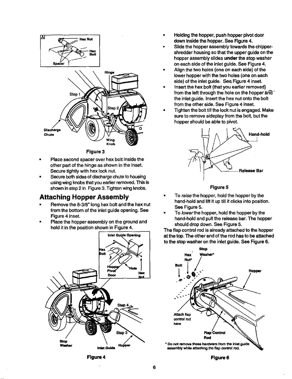
Attaching Hopper Assembly
• Remove the 8-3/8" longhex bolt and the hex nut
from the bottom ofthe inlet guide opening. See
Figure 4 inset.
• Place the hopper assembly on the ground and
hold it in the position shownin Figure 4.
Inlet Gu de Opening
|0 ,
• Holdingthe hopper, push hopper pivotdoor
down inside the hopper. See Figure 4.
• Slidethe hopper assembly towards the chipper-
shredder housing sothat the upper guideon the
hopperassembly slides under the stop washer
on each side ofthe inletguide. See Figure 4.
• Alignthe two holes (one on each side) ofthe
lower hopper withthe two holes (one on each
side) of the inletguide. See. Figure4 inset.
• Insertthe hex bolt (that you eadier removed)
fromthe leftthrough the hole on the hopper _n_ °
the inletguide. Insertthe hex nutonto the bolt
from the other side. See Figure 4 inset.
• Tighten the bolttillthe lock nut isengaged. Make
sure to remove sideplay from the bolt, butthe
hoppershould be able to pivot.
Figure 5
• To raise the hopper, holdthe hopper by the
hand-hold and liftit uptill itclicks intoposition.
See Figure 5.
• To Iowerthe hopper, hold the hopper bythe
hand-hold and pullthe release bar. The hopper
shoulddrop down. See Figure 5.
The flap controlrod isalready attached to the hopper
at the top.The other end ofthe rodhas to be attached
to the stop washer on the inlet guide. See Figure 6.
Stop .
He](' Washer*
Nut*
Bolt l
Hopper
Stop
Washer
Inlet Guide
Figure 4
Attachflap
control rod
hem
Fist
Rod
• Do not remove these hardware from the inletguide
mmernblywhile attachingthe flap control rod.
Flgure6
• Raise the hopper tillitclicks intoposition.
• Unscrew the shoulder boltfrom the stop washer
on the inletguide. See Figure 6.
• Alignthe loose end ofthe flap control rod with
the stop washer on the inletguide.
• Slidethe shoulder boltthrough the opening in
the flap controlrod. Secure tightly.See Figure 6.
&
WARNING: This flap controlrod isa safety
device to holdthe flap in place inside the
hopper while shredding branches. Do not
operate the chipper-shredder without
properly attaching thisflap control rodto the
unit
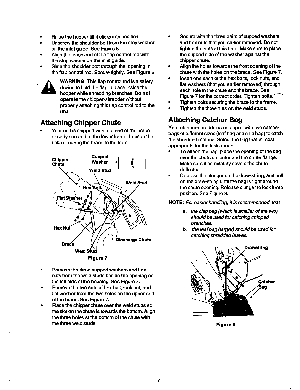
Attaching Chipper Chute
• Your unitis shipped with one end ofthe brace
already secured to the lower frame. Loosen the
boltssecuring the brace to the frame.
Cupped r
Chipper Washer--[ ( ]
Weld Stud
,----" Weld Stud
f'-'-* \
Brace
Weld
Figure 7
_Chute
• Remove the three cupped washers and hex
nuts from the weld studs beside the opening on
the left side of the housing. See Figure7.
• Remove the two sets of hex bolt, lock nut,and
fiatwasher from the two holes on the upper end
of the brace. See Figure 7.
• Place the chipper chute over the weld studs so
the sloton the chute istowards the bottom. Align
the three holes at the bottomofthe chute with
the three weld studs.
• Secure with the three pairsof cupped washers
and hex nuts thatyou eadier removed. Do not
tighten the nutsat this time. Make sure toplace
the cupped side ofthe washer against the
chipper chute.
• Align the holestowards the frontopening ofthe
chute with the holes on the brace. See Figure 7.
• Insert one each ofthe hex bolts, lock nuts, and
flat washers (that you eadier removed) through
each holein the chute and the brace. See
Figure 7 for the correct order. Tighten bolts.- --"_
• Tighten boltssecuringthe brace tothe frame.
• Tighten the three nuts on the weld studs.
Attaching Catcher Bag
Your chipper-shredder is equipped with two catcher
bags of differentsizes (leaf bag and chip bag) to catch
the shredded material,Select the bag that ismost
appropriate for the task ahead.
• To attach the bag, place the opening of the bag
over the chute deflector and the chute flange.
Make sure itcompletely covers the chute
deflector.
• Depress the plunger on the draw-string, and pull
on the draw-string until the bag istightaround
the chute opening. Release plunger tolock itinto
position.See Figure 8.
NOTE: For easier handling, it is recommended that
a. the chipbag (which issmaller of the two)
shouldbe used for catchingchipped
branches.
b. the leaf bag (larger) shouldbe used for
catching shredded leaves.
\
Figure 8
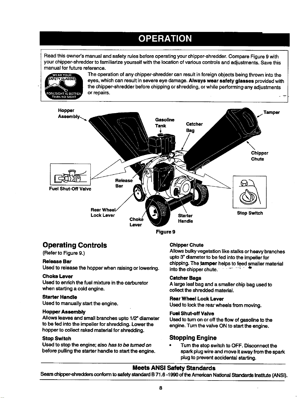
Readthisowner'smanualandsafetyrulesbeforeoperatingyourchipper-shredder.CompareFigure9with
yourchipper-shreddertofamiliarizeyourselfwiththelocationofvariouscontrolsand adjustments. Save this
manual for future reference.
The operation ofany chipper-shredder can resultin foreign objects being thrown intothe
eyes, which can result in severe eye damage. Always wear safety glasses providedwith
the chipper-shredder before chipping or shredding, orwhile performing-any adjustments
or repairs.
Hopper .Tamper
Assembly,.,_ Gasoline
Tank Catcher
Chipper
Chute
Fuel Shut-Off Valve
Lock Lever
Lever
Figure9
Starter
Handle
Stop Switch
Operating Controls
(Refer to Figure g.)
Release Bar
Used to release the hopper when raisingor lowering.
Choke Lever
Used to enrich the fuel mixture in the carburetor
when starting a cold engine.
Starter Handle
Used to manually startthe engine.
Hopper Assembly
Allows leaves and small branches upto 1/2"diameter
to be fed intothe impeller for shredding. Lower the
hopper to collect raked material for shredding.
Stop Switch
Used to stop the engine; also has to be turned on
before pullingthe starter handle tostart the engine,
Chipper Chute
Allowsbulkyvegetation like stalks or heavy branches
upto3" diameter to be fed intothe impeller for
chipping.The tamper helpsto feed smaller material
intothe chipperchute. ....... _"
Catcher Bags
A large leaf bag and a smaller chip bag used to
collectthe shredded material.
Rear Wheel Lock Lever
Used to lockthe rear wheels from moving.
Fuel Shut-off Valve
Used totum on or offthe flow of gasoline tothe
engine. Tum the valve ON to start the engine.
Stopping Engine
• Tum the stop switch toOFF, Disconnectthe
spark plugwire and move itaway from the spark
plug toprevent accidental starting.
Meets ANSI Safety Standards
Sears chipper-shredders conformtosafety standardB71,6 -1990 ofthe AmericanNationalStandardsInstitute(ANSI).
8
Lowering Hopper Assembly
In order to rake leaves intothe hopper, you will need
to lower the hopper.
• To lower the hopper assembly, use one hand to
grasp the hand-hold at the top ofthe hopper
assembly and liftslightly. See Figure 5.
• Pul!up onthe release bar, and lowerthe hopper
assembly to the drop-down position. Release
the bar. See Figure 5.
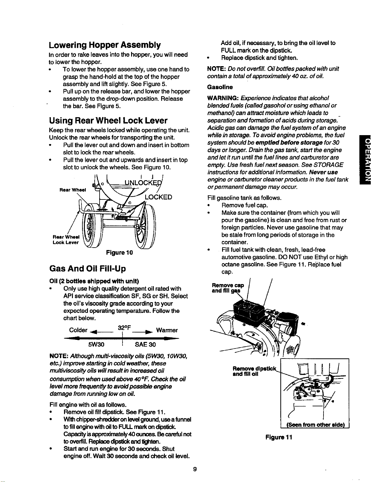
Using Rear Wheel Lock Lever
Keep the rear wheels locked while operating the unit.
Unlock the rear wheels for transporting the unit.
• Pullthe lever outand down and insert in bottom
slot to lockthe rear wheels.
• Pull the lever out and upwards and insert intop
slot to unlock the wheels. See Figure 10.
I J
Rear Wheel
Rear Wheel
Lock Lever
Figure 10
Gas And Oil Fill-Up
Oil (2 bottles shipped with unit)
• Only use high quality detergent oil rated with
API service classification SF, SG or SH. Select
the oil'sviscositygrade according to your
expected operating temperature. Follow the
chart below.
Colder _1-- 32°F Warmer
- 5W30 I SAE 30 -
NOTE: Althoughmulti-viocosity oils(5W30, 10W30,
etc.) improve starting in cold weather, these
multiviscosityoilswillresultin increased oil
consumption when used above 40°F. Check the oil
level more froquentiyto avoidpossible engine
damage from running low on oil.
Fill engine with oilas follows.
• Remove oilfilldipstick.See Figure 11.
• W'rthchipper-shredderonlevelground,usea funnel
tofillenginewithoilto FULL markondip_ck.
Capacityisapproximately40 ounces.Becarefulnot
toover u, dipsUckondUghton.
• Start and runengine for 30 seconds. Shut
engine off. Wait 30 seconds and check oillevel.
Add oil, ifnecessary, to bringthe oillevel to
FULL mark onthe dipstick.
Replace dipstickand tighten.
NOTE: Do not overfill. Oil bottlespacked with unit
contain a total ofapproximately 40 oz. ofoil.
Gasoline
WARNING: Experience indicates thatalcohol
blended fuels (calledgasohol or using ethanol or
methanol) can attract moisture whichleads to
separation and formationofacids during storage.-
Acidicgas can damage the fuel system ofan engine
whilein storage. Toavoid engine problems, the fuel
system shouldbe emptied before storage for 30
L
days orlonger. Drain the gas tank, start the engine
and let itrun until thefuel lines and carburetor are
empty. Use fresh fuelnext season. See STORAGE
instructionsfor additionalinformation. Never use
engine orcarburetor cleaner products in the fuel tank
or permanent damage may occur.
Fill gasoline tank as follows.
• Remove fuel cap.
• Make sure the container (fromwhich you will
pour the gasoline) is clean and free from rustor
foreign particles. Never use gasoline that may
be stale from long periods of storage inthe
container.
• Fillfuel tank with clean, fresh, lead-free
automotive gasoline. DO NOT use Ethyl or high
octane gasoline. See Figure 1t. Re'placefuel
cap.
end fill
and fill ©
Figure 11
9
A
WARNING: Do not fill closer than 1/2
inchfrom the top of the fuel tank to prevent
spills and to allow for fuel expansion. If
gasoline isaccidently spilled, move chipper-
shredder away from area of spill.Avoid
creating any source of ignitionuntilgasoline
vapors have disappeared.
°
Check the fuel level periodically toavoid running
out of gasoline while operating the chipper-
shredder.
Ifthe unitruns out of gas as itis shredding or
chipping, itmay be necessary to unclogthe unit
before itcan be restarted. Refer to Removing
the Flail Screen inSERVICE AND
ADJUSTMENT section.
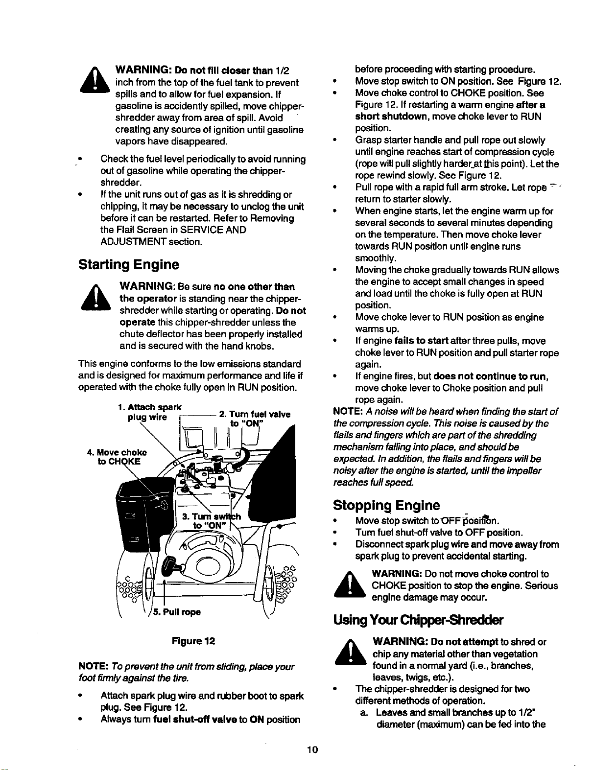
Starting Engine
WARNING: Be sure no one other than
the operator isstanding near the chipper-
shredder while startingor operating. Do not
operate this chipper-shredder unless the
chute deflector has been propedy installed
and is secured with the hand knobs.
This engine conforms tothe low emissions standard
and isdesigned for maximum performance and life if
operated with the choke fully open in RUN position.
1. Attach spark
plug wire
2. Turn fuel valve
4. Move choke
5. Pull rope
Flgure 12
NOTE: Toprevent the unitfrom sliding,place your
foot firmlyagainst the tire.
• Attach spark plug wire and robber bootto spark
plug. See Figure 12.
• Always tum fuel shut.off valve to ON position
before proceeding with starting procedure.
• Move stopswitch toON position. See Figure 12.
• Move choke controlto CHOKE position.See
Figure 12. If restartinga warm engine after a
short shutdown, move choke lever to RUN
position.
• Grasp starter handle and pull rope out slowly
until engine reaches startof compression cycle
(rope willpullslightlyharder_atthis point). Letthe
rope rewind slowly.See Figure 12.
• Pullrope with a rapid full arm stroke. Let rope --'"
return to starter slowly.
• When engine starts,let the engine warm upfor
several seconds to several minutes depending
on the temperature. Then move choke lever
towards RUN positionuntilengine runs
smoothly.
• Movingthe choke gradually towards RUN allows
the engine to accept small changes inspeed
and load untilthe choke isfully open at RUN
position.
• Move choke lever to RUN position as engine
warms up.
• Ifengine fails to start after three pulls,move
choke lever to RUN positionand pull starter rope
again.
• Ifengine fires, but does not continue to run,
move choke lever toChoke positionand pull
rope again.
NOTE: A noise willbe heard when finding thestart of
the compression cycle. Thisnoise iscaused by the
flailsand fingers whichare part ofthe shredding
mechanism fallingintoplace, and shouldbe
expected. In addition,the flailsand fingers willbe
noisyafter theengine isstarted, until the impeller
reaches fullspeed.
Stopping Engine
• Move stop switchtoOFF-_osit'_n.
• Turn fuel shut-offvalve to OFF position.
• Disconnectspark plug wire and move away from
spark plugto prevent accidental starting.
,_ WARNING: Do not move choke controlto
CHOKE position to stop the engine. Sedous
engine damage may occur.
Using Your Chipper-Shredder
_lb ARNING: Do not attempt to shred or
chip any material otherthan vegetation
found in a normal yard (i.e., branches,
leaves, twigs,etc.).
• The chipper-shredder isdesigned for two
different methods ofoperation.
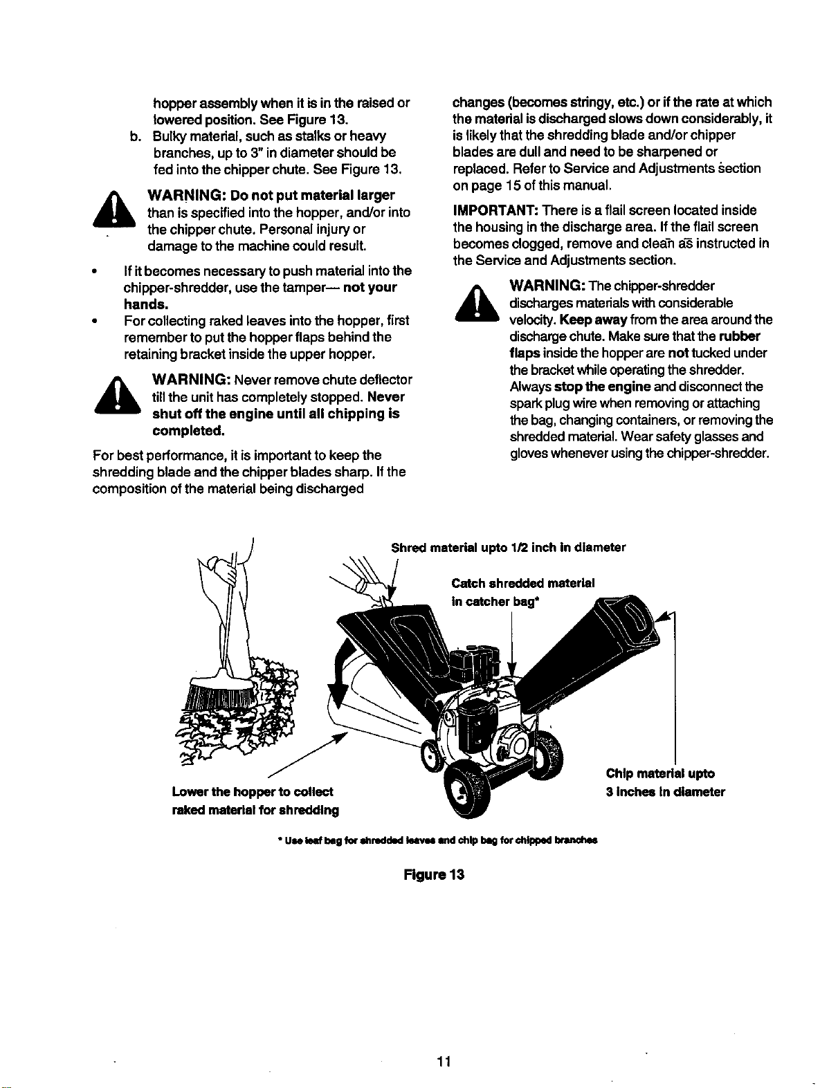
a. Leaves and small branches up to 1/2"
diameter (maximum) can be fed intothe
10
h,
hopper assembly when itis in the raisedor
lowered position.See Figure 13.
Bulky material, such as stalks or heavy
branches, up to 3"in diameter should be
fed intothe chipper chute. See Figure 13.
A
WARNING: Do not put material larger
than isspecified intothe hopper, and/or into
the chipper chute. Personal injuryor
damage to the machine could result.
• Ifitbecomes necessary topush material intothe
chipper-shradder, use the tamper-- not your
hands.
• Forcollecting raked leaves intothe hopper, first
remember to put the hopper flaps behind the
retaining bracket inside the upper hopper.
WARNING: Never remove chute deflector
tillthe unithas completely stopped. Never
shut off the engine until all chipping is
completed.
For best performance, it isimportantto keep the
shredding blade and the chipper blades sharp. Ifthe
composition ofthe material being discharged
changes (becomes stringy, etc.) or ifthe rate at which
the material isdischarged slows down considerably, it
islikelythat the shredding blade and/or chipper
blades are dulland need to be sharpened or
replaced. Refer to Service and Adjustments section
on page 15 ofthis manual.
IMPORTANT: There isa flail screen located inside
the housing inthe discharge area. Ifthe flail screen
becomes clogged, remove and clean a_ instructed in
the Service and Adjustments section.
A
WARNING: The chipper-shredder
dischargesmaterialswithconsiderable
velocity.Keep away from the area aroundthe
dischargechute.Make sure thatthe rubber
flaps insidethe hopperare not tuckedunder
the bracketwhile operatingtheshredder.
Alwaysatop the engine and disconnectthe
sparkplugwire when removingorattaching
thebag,changingcontainers,or removingthe
shreddedmaterial.Wear safety glassesand
gloveswhenever usingthe chipper-shredder.
Shred matedal upto 1/2 inch In diameter
Catch shredded materiel
In catcher beg*
Lowerthe hopperto collect
raked materielfor shredding
• Use leaf beg for _ltrodded klws and chip beg forchipped branches
Figure 13
Chip matedel upto
3 Inches In diameter
11
General Recommendations
• Always observe safety rules when performing
any maintenance,
• The warranty on this chipper shredder does not
cover items that have been subjected tooperator
abuse or negligence. To receive fullvalue from
the warranty, operator must maintain the chipper-
shredder as instructedin this manual,
• Some adjustments will need to be made
periodically to maintain your unitpropedy.
• All adjustments inthe Service and Adjustments
section ofthis manual should be checked at least
once each season.
• Followthe maintenance schedule given below.
• Periodically check all fasteners and make sure
these are tight.
WARNING: Always stop the engine and
disconnect the spark plugwire before
performingany maintenance or adjustments.
Never remove discharge chute tillthe
engine has completely stopped.
Cleaning
• Clean the chipper-shredder byrunning water
from a hose throughthe hopper assembly and
chipper chute withthe engine running.Allow the
chipper-shredder to dry thoroughly.
• Wash the bag periodicallywithwater. Allow todry
thoroughly in the shade. Do not use heat.
Engine Maintenance
Engine Oil
• Only use high qualitydetergent oil rated with API
service classification SF, SG or SH. Select the
oil'sviscositygrade according toyour expected
operating temperature. Refer to page 9 of this
manual for viscositychart.
• The four-cycle engine of yourchipper-shredder
willnormallyconsume some oil. Therefore, check
engine oillevel regularlyapproximately every five
hours of operation and before each usage.
• Stop engine and wait several minutes before
checking oillevel. With engine on level ground,
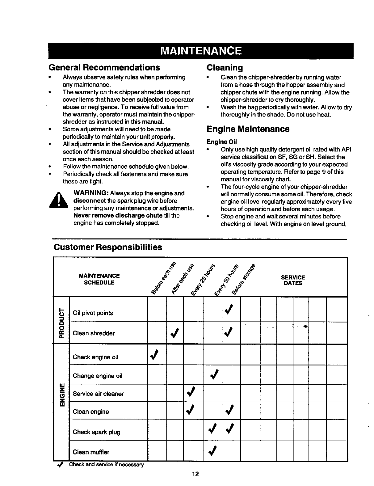
Customer Responsibilities
.A,HTE...CE oO SE.V,C0
SCHEDULE _o_e _e_ =_ __ _ DATES
._ Oil pivot points 4
mO Clean shredder _ 4 _ "
O.
Check engine oil
Change engine oil
uJ
z
Service air cleaner _'
m
IM
Clean engine 4 4
Check spark plug _ 4
Clean muffler
Checkandserviceifnecessary
12
theoilmustbetoFULLmarkondipstick.
Changeengineoilevery50hoursofoperation
undernormaloperatingconditions.Changeoil
every25hourswhenoperatingnderheavy
loadorinhightemperatures.
ToDrainOil
Drainoilwhileengineiswarm.Followinstructions
. givenbelow.
• Removeoildrainplug.Catchoilina suitable
container.
• When engine isdrained ofall oil, replace drain
plug securely.
• Refill with fresh oil. Refer to GAS AND OIL
FILL-UP section on page 9.
• Replace dipstick.
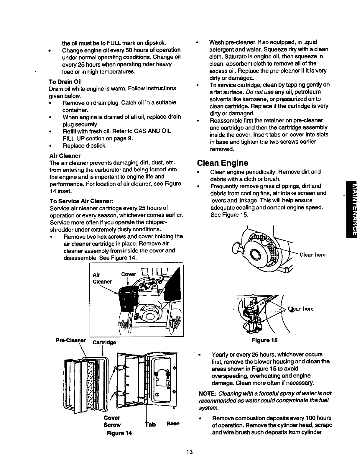
Air Cleaner
The air cleaner preventsdamaging dirt, dust,etc.,
from entering the carburetor and being forced into
the engine and is importantto engine life and
performance. For locationof air cleaner, see Figure
14 inset.
To Service Air Cleaner:
Service air cleaner cartridgeevery 25 hours of
operation or every season, whichever comes earlier.
Service more often ifyou operate the chipper-
shredder under extremely dusty conditions.
• Remove two hex screws and cover holdingthe
air cleaner cartddge in place. Remove air
cleaner assembly from inside the cover and
disassemble. See Figure 14.
Air Cover
Cleaner
Pre-Cleaner
Cartridge
Cover
Screw
Figure 14
"ab Base
• Wash pre-cleaner, ifso equipped, in liquid
detergent and water. Squeeze dry with a clean
cloth. Saturate in engine oil, then squeeze in
clean, absorbent clothto remove all of the
excess oil. Replace the pre-cleaner ifitisvery
dirty or damaged.
• To service cartridge, clean by tapping gentlyon
a flat surface. Do notuse any oil,petroleum
solvents like kerosene, or pressurized air to
clean cartridge. Replace ifthe cartridge isvery
dirtyor damaged.
• Reassemble first the retainer on pre-cleaner
and cartridge end then the cartridge assembly
insidethe cover. Insert tabs on cover intoslots
in base and tighten the two screws eadier
removed.
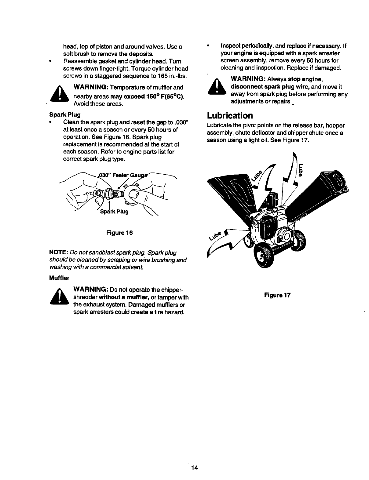
Clean Engine
• Clean engine periodically. Remove dirtand
debris with a clothor brush.
• Frequently remove grass clippings, dirt and
debris from cooling fins, air intake screen and
levers and linkage. This will help ensure
adequate cooling and correct engine speed.
See Figure 15.
_ Clean here
, _ C_ean here
Figure 15
Yeady or every 25 hours, whichever occurs
first, remove the blower housing and clean the
areas shown in Figure 15 to avoid
overspeeding, overheating and engine
damage. Clean more often if necessary.
NOTE: Cleaning witha forceful spray ofwater isnot
recommended as watercould contaminate the fuel
system.
• Remove combustion deposits every 100 hours
ofoperation. Remove the cylinder head, scrape
and wire brush such deposits from cylinder
13
head, top ofpiston and around valves. Use a
soft brush to remove the deposits.
Reassemble gasket and cylinder head. Turn
screws down finger-tight.Torque cylinder head
screws in a staggered sequence to 165 in.-Ibs.
,_ WARNING: Temperature of muffler and
nearby areas may exceed 150° F(65°C).
Avoid these areas.
Spark Plug
• Clean the spark plug and reset the gap to .030"
at least once a season or every 50 hours of
operation. See Figure 16. Spark plug
replacement is recommended at the start of
each season. Refer toengine parts listfor
correct spark plugtype.
• Inspect periodically, and replace ifnecessary. If
your engine isequipped with a spark arrester
screen assembly, remove every 50 hours for
cleaning and inspection. Replace ifdamaged•
_lb WARNING: Always stop engine,
disconnect spark plug wire, and move it
away from spark plug before performing any
adjustments or repairs.
Lubrication
Lubricatethe pivot pointson the release bar, hopper
assembly, chute deflector and chipper chute once a
season using a light oil. See Figure 17.
Figure 16
NOTE: Do not sandblast spark plug. Spark plug
shouldbe cleaned by scraping or wire brushing and
washing witha commercial solvent.
Muffler
WARNING: Do not operate the chipper-
shredder without a muffler, or tamper with
the exhaust system. Damaged mufflersor
spark arresters could create s fire hazard.
Figure 17
14
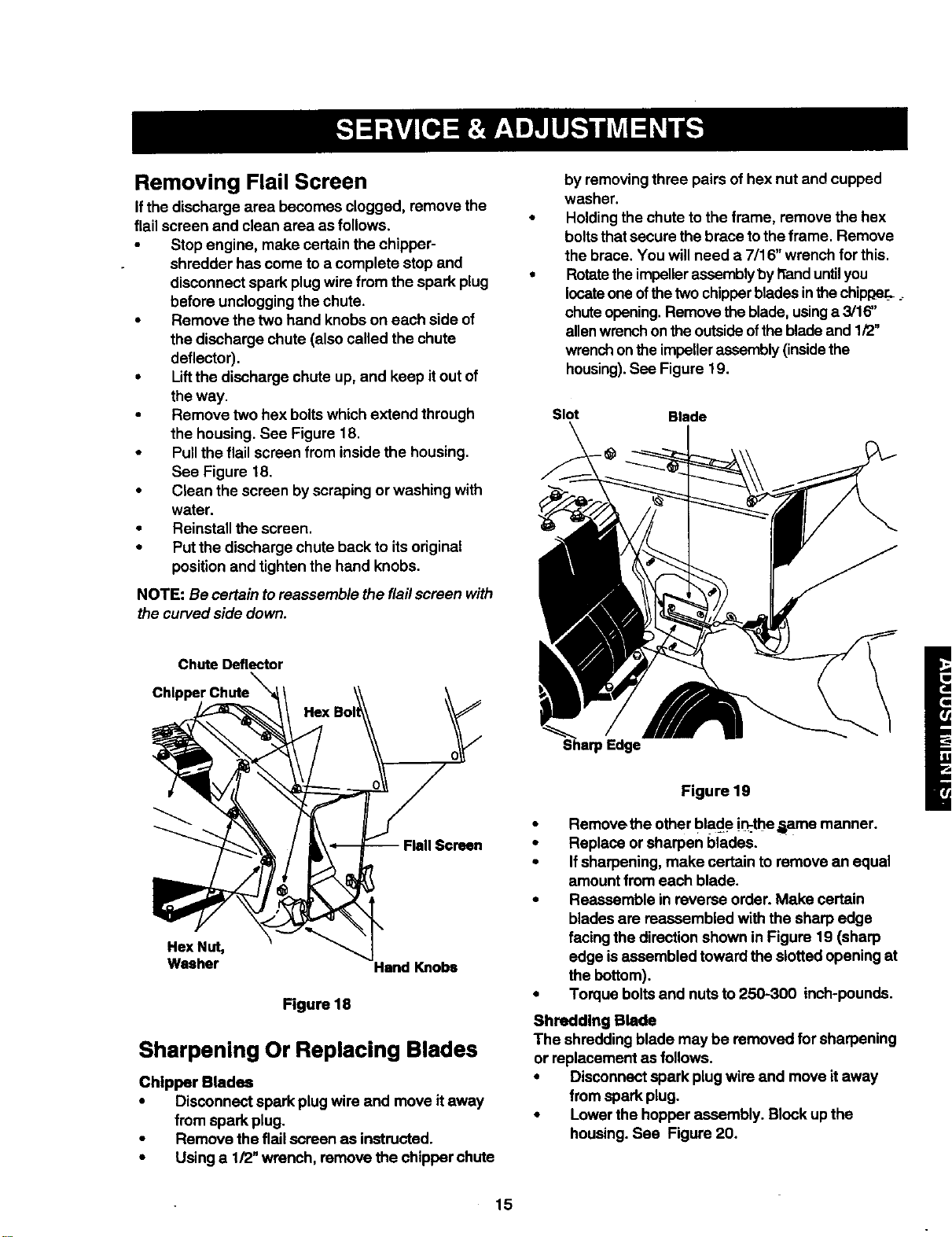
Removing Flail Screen
ifthe discharge area becomes clogged, remove the
flailscreen and clean area as follows.
• Stop engine, make certain the chipper-
shredder has come to a complete stop and
disconnect spark plugwire from the spark plug
before unclogging the chute.
• Remove the two hand knobs on each side of
the discharge chute (also called the chute
deflector).
• Liftthe discharge chute up,and keep itout of
the way.
• Remove two hex boltswhich extend through
the housing. See Figure 18.
• Pullthe flailscreen from inside the housing.
See Figure 18.
• Clean the screen byscraping or washing with
water.
• Reinstall the screen.
• Put the discharge chute back to itsoriginal
position and tighten the hand knobs.
NOTE: Be certain to reassemble the flailscreen with
the curved side down.
Chute Deflector
by removingthroe pairs ofhex nut and cupped
washer.
Holdingthe chute to the frame, remove the hex
boltsthat secure the brace to the frame. Remove
the brace. You will need a 7/16" wrench for this.
Rotatetheimpellerassemblyby _and untilyou
locateone ofthe two chipperblades inthe chip_er_
chuteopening.Remove theblade, usinga 3/16"
allenwrenchon the outsideofthebladeand 1/2"
wrenchonthe impellerassembly(insidethe
housing).See Figure 19.
Slot Blade
Flail Screen
Hex Nut,
Washer
Hand Knobs
Figure 18
Sharpening Or Replacing Blades
Chipper Blades
• Disconnect spark plug wire and move itaway
from spark plug.
• Remove the flailscreen as instructed.
• Using a 1/2" wrench, remove the chipper chute
Figure 19
• Remove the other blade i_the _ame manner.
• Replace or sharpen blades.
• Ifsharpening, make certain to remove an equal
amount from each blade.
• Reassemble in reverse order. Make certain
blades are reassembled with the sharp edge
facing the direction shown in Figure 19 (sharp
edge isassembled toward the slottedopening at
the bottom).
• Torque boltsand nutsto 250-300 inch-pounds.
Shredding Blade
The shredding blade may be removed for sharpening
or replacement as follows.
• Disconnect spark plug wire and move itaway
from spark plug.
• Lower the hopper assembly. Block up the
housing. See Figure 20.
15
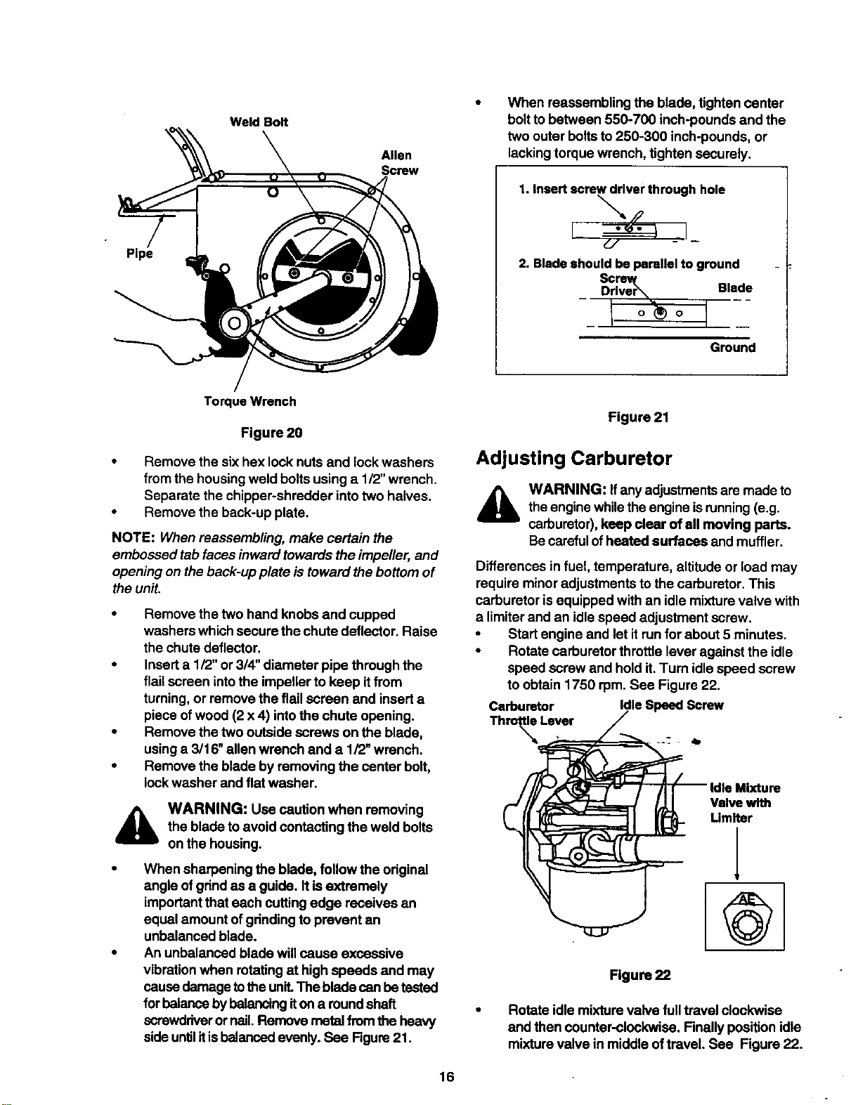
Pipe
Weld Bolt
Allen
Screw
When reassembling the blade, tighten center
bolttobetween 550-700 inch-pounds and the
two outer boltsto 250-300 inch-pounds, or
lacking torque wrench, tighten securely.
1. Insertscrew driver through hole
"-,,.p
2. Bladeshould be parallel to ground
Sc
D:d_e_ Blade
I I-
Ground
Torque Wrench
Figure 20
• Remove the six hex lock nuts and lock washers
from the housingweld boltsusing a 112"wrench.
Separate the chipper-shredder intotwo halves.
• Remove the back-up plate,
NOTE: When reassembling, make certain the
embossed tab faces inward towards the impeller, and
opening on theback-up plate is toward the bottom of
the unit.
• Remove the two hand knobsand cupped
washers which secure the chute deflector. Raise
the chute deflector,
• Insert a 112"or 314"diameter pipe through the
flail screen intothe impeller to keep itfrom
turning,or remove the flailscreen and inserta
piece ofwood (2 x 4) intothe chute opening.
• Remove the two outside screws on the blade,
using a 3116"allen wrench and a 1/2" wrench,
• Remove the blade by removing the center bolt,
lock washer and flat washer.
WARNING: Use caution when removing
the blade toavoid contacting the weld bolts
on the housing.
When sharpening the blade, follow the odginal
angle of grindas a guide. It isextremely
importantthat each cutting edge receives an
equal amount ofgrinding to prevent an
unbalanced blade.
An unbalanced blade will cause excessive
vibration when rotatingat high speeds and may
cause damage tothe unit.The blade canbe tested
for balanceby balancingiton a roundshaft
screwdriverornail. Remove metal from the heavy
side untilitisbalanced evenly. See Figure21.
Figure 21
Adjusting Carburetor
WARNING: If anyadjustmentsare made to
the engine whiletheengine isrunning(e.g.
carburetor),keep clear of all moving parts.
Becarefulofheated surfaces and muffler.
Differences in fuel,temperature, altitude or load may
require minor adjustments to the carburetor. This
carburetor isequipped with an idle mixturevalve with
a limiter and an idle speed adjustment screw.
• Start engine and let it runfor about 5 minutes.
• Rotate carburetor throttle lever against the idle
speed screw and hold it.Turn idlespeed screw
to obtain 1750 rpm. See Figure 22.
Carburetor Idle Speed Screw
Thro_ Lever
@
Figure 22
Rotate idle mixturevalve fulltravel clockwise
and then counter-clockwise. Finally position idle
mixture valve in middle oftreveL See Figure 22.
16
Checkidlespeedand re-adjust to 1750 rpm, if
necessary.
Engine should accelerate smoothly, If itdoes
not, adjust idle mixturevalve counter-elcckwise
1/8 turn.
_lb ARNING: Air cleaner and itscover must
be assembled tothe carburetor before
starting the engine.
Adjusting Engine Speed
The engine speed on your chipper-shredder has
been set at the factory. Do not attempt to increase
engine speed or itmay resultin personal injury. If you
believe the engine isrunningtoo fast ortoo slow,take
yourchipper-shredder to the nearest SEARS service
center for repair and adjustment.
Tires
Recommended operating tire pressure is 24 p.s.i.
(sidewall oftire may give tire manufacturer's
recommended pressure). Equal tire pressure should
be maintained on bothtires.
_lb ARNING: Excessivepressurewhenseating
beadsmaycausetire/rimassemblytoburstwith
force sufficienttocauseserious injury,
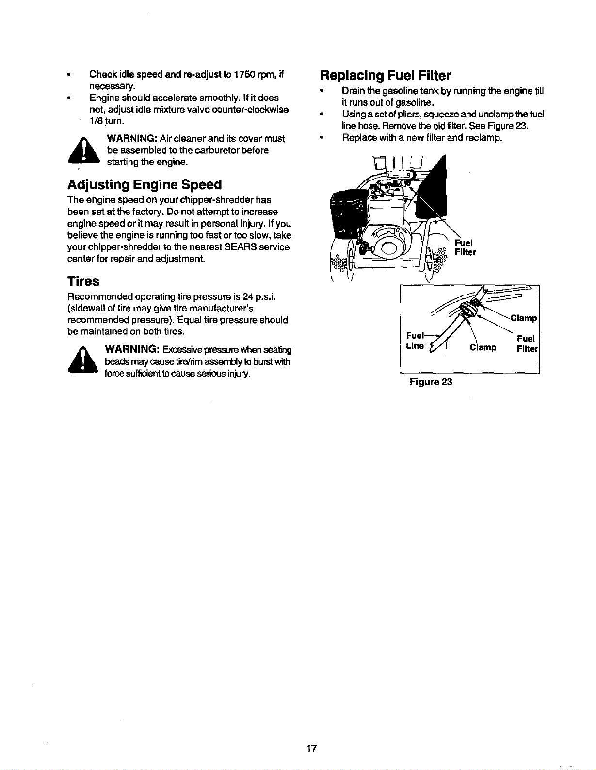
Replacing Fuel Filter
• Drain the gasoline tank by runningthe engine till
itruns out ofgasoline.
• Usingaset ofpliers,squeezeand unclampthe fuel
linehose.Removethe oldfilter, See Figure23,
• Replace with a new filterand reclamp.
Filter
Clamp
Figure 23
17
Prepareyourchipper-shredderfor storage at the end
ofthe season or ifthe unitwillnot be used for 30 days
or more.
WARNING: Never store machine with fuel
inthe fuel tank inside of buildingwhere
fumes may reach an open flame or spark,
or where ignitionsources are present such
as hot water and space heaters, furnaces,
clothes dryers, stoves, electric motors, etc.
A yearly check-up by your localSears service center
isa good way to make certain yourchipper-shredder
willprovide maximum performance for the next
season,
Chipper-Shredder
• Clean the chipper-shredder thoroughly.
• Wipe unitwith an oiled rag toprevent rust (use a
light oil or silicone).
Engine
IMPORTANT: Itis importantto prevent gum deposits
from forming in essential fuel system parts such as
carburetor, fuel filter, fuel hose, or tank during
storage. Also, experience indicatesthat alcohol
blended fuels (called gasohol or using ethanol or
methanol) can attract moisture which leads to
separation and formation of acids during storage.
Acidic gas can damage the fuel system of an engine
while in storage.
• Drain the fuel tank.
• Start the engine and let itrun untilthe fuel lines
and carburetor are empty.
• Drain carburetor.
• Never use engine or carburetor cleaner
products in the fuel tank or permanent damage
may occur.
Use fresh fuel next season.
NOTE: Fuel stabilizer isan acceptable alternative in
minimizing the formation offuel gum deposits during
storage.
• Add stabilizer to gasoline infuel tank or storage
container.
• Always follow the mix ratiofound on stabilizer "
container.
• Run engine at least 10 minutes after adding
stabilizer toallow the stabilizer to reach the
carburetor.
• Do not drain the gas tank and carburetor if using
fuel stabilizer. Drain all the oilfrom the
crankcase (this shouldbe done after the engine
has been operated and is stillwarm) and refill
the crankcase with fresh oil.
• Ifyou have drained the fuel tank, protect the
insideof the engine as follows.
• Remove spark plug, pour approximately 1/2
ounce(approximately one tablespoon) ofengine
oilintocylinder and crank slowlyto distribute oil.
• Replace spark plug.
Other
Do not store gasoline from one season to
another,
Replace your gasoline can ifyour can startsto
rust. Rust and/or dirtin your gasoline willcause
problems. Store unit ina clean, dry area. Do not
stere nextto corrosive materials, such as
fertilizer.
NOTE: Ifstoringin an unventilated or metal storage
shed, be certain torus_roof the equipment bycoating
with a light oilof silicone.
h
18
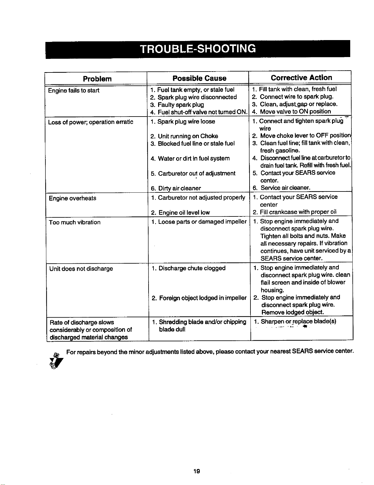
Problem Corrective Action
Engine fails to start
Loss ofpower; operation erratic
Engine overheats
Too much vibration
Unit does not discharge
Possible Cause
1. Fuel tank empty, or stale fuel
2. Spark plug wire disconnected
3. Faulty spark plug
4. Fuel shut-offvalve notturned ON.
1. Spark plugwire loose
2. Unit runningon Choke
3. Blocked fuel line or stale fuel
4. Water or dirt infuel system
5. Carburetor out ofadjustment
6. Didy air cleaner
1. Carburetor not adjusted properly
2. Engine oil level low
1. Loose parts or damaged impeller
1. Discharge chute clogged
2. Foreign object lodged in impeller
Rate of discharge slows 1. Shredding blade and/or chipping
considerably or composition of blade dull
discharged material changes
1. Fill tank with clean, fresh fuel
2. Connect wire to spark plug.
3. Clean, adjust.gap or replace.
4. Move valve toON position
1. Connect and tighten spark plug
wire
2. Move choke lever to OFF position
3. Clean fuel line;filltank with clean
fresh gasoline.
4. Disconnectfuellineat carburetorto
drainfuel tank. Refillwith fresh fuel.
5. ContactyourSEARS service
center.
6. Servise air cleaner.
1. Contact your SEARS service
center
2. Fillcrankcase with proper oil
1. Stop engine immediately and
disconnect spark plug wire.
Tighten all boltsand nuts. Make
all necessary repairs. Ifvibration
continues, have unitserviced bya
SEARS service center.
1. Stop engine immediately and
disconnect spark plug wire. clean
flail screen and inside of blower
housing.
2. Stop engine immediately and
disconnect spark plugwire.
Remove lodged object.
1. Sharpen or_replaceblade(s)
. _. =,o lip
_y For repairs beyond the minor adjustments listed above, please contact your nearest SEARS service center.
19
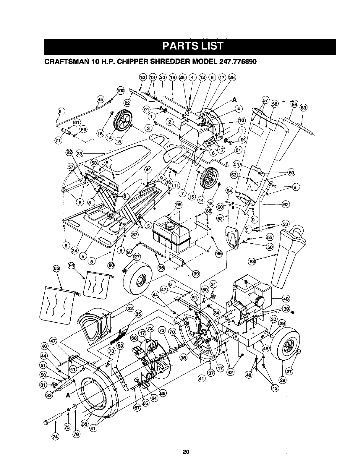
CRAFTSMAN 10 H.P. CHIPPER SHREDDER MODEL 247,775890
2O
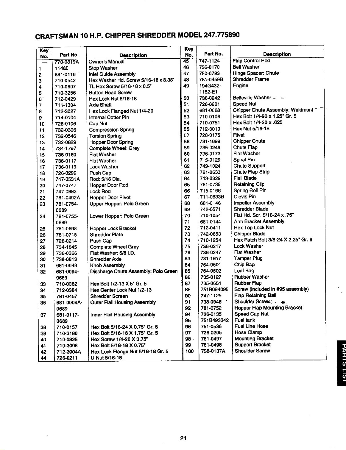
CRAFTSMAN 10 H.P. CHIPPER SHREDDER MODEL 247.775890
Key
No.
I
2
3
4
5
6"
7
8
9
10
11
12
13
14
15
16
17
18
19
2O
21
22
23
24
25
26
27
28
29
30
31
32
33
34
35
36
37
38
39
4O
41
42
44
Part No.
r70-0819A
11480
681-0118
710-0542
_10-0607
710-3256
712-0429
711-1304
i 712-3027
Description
Owner's Manual
Stop Washer
Inlet Guide Assembly
Hex Washer Hd. Screw 5/16-18 x8,38"
TL Hex Screw 5/16-18 x0.5"
Button Head Screw
Hex Lock Nut 5/16-18
Axle Shaft
Hex Lock Flanged Nut 114-20
Key
No. Pa_ No.
45 747-1124
46 736-0170
!47 750-0793
48 781-0459B
49 194G432-
1182-E1
50 736-0242
51 726-0201
52 381-0068
Description
Flap Control Rod
BellWasher
Hinge Spacer: Chute
Shredder Frame
Engine
BellevilleWasher - -
Speed Nut
Chipper Chute Assembly: Weldment - "_
_14-0104
726-0106
732-0306
732-0546
732-0629
734-1797
736-0160
736-0117
736-0119
726-0299
747-0531A
747-0747
747-0982
781-0492A
781-0754-
0689
781-0755-
0689
781-0698
781-0715
726-0214
734.1845
736-0366
738-0813
681-0048
Internal Cotter Pin
Cap Nut
Compression Spring
Torsion Spring
Hopper Door Spring
Complete Wheel: Grey
Fiat Washer
Flat Washer
Lock Washer
Push Cap
Rod: 5/16 Dia.
Hopper Door Rod
Lock Rod
Hopper Door Pivot
Upper Hopper: Polo Green
Lower Hopper: Polo Green
Hopper LockBracket
Shredder Plate
Push Cap
Complete Wheel Grey
Flat Washer:,5/8 I.D.
Shredder Axle
KnobAssembly
53 710-0106
54 710-0751
55 712-3010
57 728-0175
58 731-1899
59 735-0249
60 736-0173
61 715-0129
62 749-1024
63 781-0633
64 719-0329
65 781-0735
66 715-0166
67 711-0833B
68 681-0146
69 742-0571
70 710-1054
71 681-0144
72 712-0411
73 742-0653
74 710-1254
75 736-0217
76 736-0247
83 731-1617
84 764-0501
Hex Bolt 1/4-20 x 1.25" Gr. 5
Hex Bolt 1/4-20 x .625
Hex Nut 5/16-18
Rivet
Chipper Chute
Chute Flap
Flat Washer
Spiral Pin
Chute Support
Chute Flap Strip
Flail Blade
Retaining Clip
Spring Roll Pin
Clevis Pin
Impeller Assembly
;hredder Blade
Flat Hd. Scr. 5/16-24 x .75"
\rm Bracket Assembly
Hex Top Lock Nut
Chipper Blade
Hex Patch Bolt 3/8-24 X 2.25" Gr. 8
LockWasher
Flat Washer
Tamper Plug
Chip Bag
681-0094-
0689
710-0382
712-0384
781-0457
681-0004A-
0689
681-0117-
0689
710-0157
1710-3180
710-0825
710-3008
712-3004A
726-0211
Discharge Chute Assembly: Polo Green
Hex Bolt 1/2-13 X5" Gr. 5
Hex Center LockNut 1/2-13
Shredder Screen
Outer Flail Housing Assembly
Inner Flail Housing Assembly
Hex Bolt5/16-24 X 0.75" Gr. 5
Hax Bolt 5/16-18 X 1.75" Gr. 5
Hex Screw 1/4-20 X 3.75"
Hex Bolt 5/16-18 X 0.75"
Hex Lock Flange Nut 5/16-18 Gr. 5
U Nut 5/16-18
85 764-0502
86 735-0127
87 735-0651
88 751B094095
90 747-1125
91 738-0946 '
92 781-0752
94 726-0135
95 751B493342
96 751-0535
97 726-0205
98, 781-0497
99 781-0498
100 736-0137A
Leaf Bag
Rubber Washer
Rubber Flap
Screw (included in #95 assembly)
Flap Retaining Bail
Shoulder _ScrJew_- ,b
Hopper Flap Mounting Bracket
Speed Cap Nut
Fuel tank
Fuel Line Hose
Hose Clamp
Mounting Bracket
Support Bracket
Shoulder Screw
21
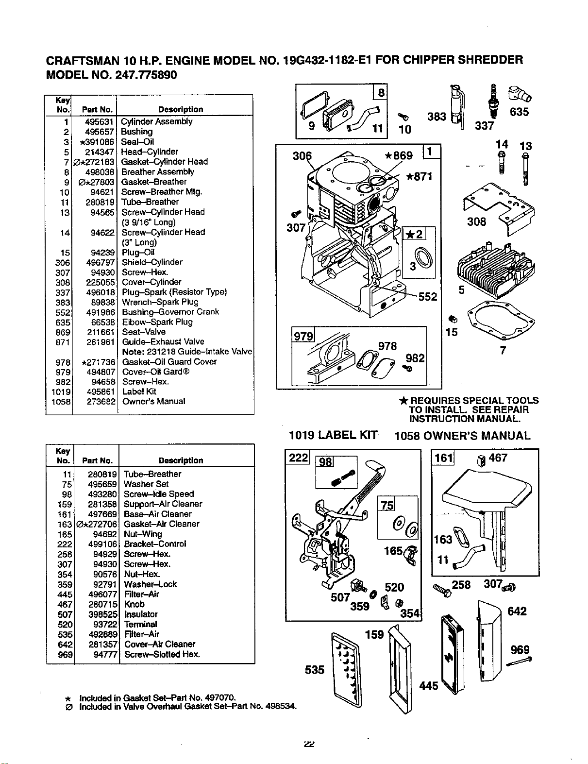
CRAFTSMAN 10 H.P. ENGINE MODEL NO. 19G432-1182-E1 FOR CHIPPER SHREDDER
MODEL NO. 247.775890
Key
No. Part No.
1 495631
2 495657
3 .391086
5 214347
7 _.272163
8 498038
9 _27803
10 94621
11 280819
13 94565
14
15
306
307
306
337
383
552
635
869
871
978
979
982
1019
1058
94622
94239
496797
94930
225055
496018
69838
491986
66538
211661
261961
*271736
494807
94658
495861
273682
Description
Cylinder Assembly
Bushing
Seal-Oil
Head-Cylinder
Gasket-Cylinder Head
Breather Assembly
Gasket-Breather
Screw-Breather Mtg.
Tube-Breather
Screw-Cylinder Head
(3 9/16" Long)
Screw-Cylinder Head
(3" Long)
Plug-Oil
Shield-Cylinder
Screw-Hex.
Cover-Cylinder
Plug-Spark (Resistor Type)
Wrench-Spark Plug
Bushing-Governor Crank
Elbow-Spark Plug
I Seat-Valve
Guide-Exhaust Valve
Note: 231218 Guide-Intake Valve
Gasket-Oil Guard Cover
Cover-Oil Gard®
Screw-Hex.
Label Kit
Owner's Manual
_0 383 337
8
1 14 13
.871 - - =
REQUIRES SPECIAL TOOLS
TO INSTALL. SEE REPAIR
INSTRUCTION MANUAL.
1019 LABEL KIT 1058 OWNER'S MANUAL
Key
No.
11
75
98
159
161
163
165
222
258
307
354
359
445
467
5O7
520
535
642
969
Part NO. Description
280819 Tube-Breather
495659 Washer Set
493280 ScrevP-Idle Speed
281358 Support-Air Cleaner
497669 Base-Air Cleaner
_272706 Gasket-Air Cleaner
94692 Nut-Wing
499106 Bracket-Control
94929 Screw-Hex.
94930 Screw-Hex.
90576 Nut-Hex.
92791 Washer-Lock
496077 Filter-Air
280715 Knob
398525 Insulator
93722 Terminal
492889 Filter-Air
281357 Cover-Air Cleaner
94777 Screw-Slotted Hey,.
I
* Included in Gasket Set-Pad No. 497070.
O Included in Valve Overhaul Gasket Set-Part No. 498534.
165_
_ 467
_1_258 307_
642
zz
CRAFTSMAN 10 H,P. ENGINE MODEL NO. 19G432-1182-E1 FOR CHIPPER SHREDDER
MODEL NO, 247.775890
Key
No. Part No. Description
12
15A
16
77
18
19
20
21
22
24
25
26
27
28
29
30
32
33
34
35
40
45
46
146
219
220
230
244
411
524
614
616
741
868
*271701
*27876
*27877
91488
495866
29530
496981
295964
*391086
281658
93585
94690
222698
499907
499908
499909
499910
499721
299743
391670
391671
391672 _
263181
499911
499920
390401
390773
222113
94670
263017
261056
65906
221596
260933
214786
94388
497037
221551
94927
230318
94802
281370
93306
496818
263625
497656
Gasket-Crankcase (.015" Thick, Std.)
Gasket--Crankcase (.005" Thick)
Gasket-Crankcase (.009" Thick)
Plug-Oil
Crankshaft
Bearing-Ball
Cover-Crankcase
Bushing
Seal-Oil
Cap-Oil Fill
Screw-Hex.
Screw-Hex. (in Position #1)
Key-Flywheel
Piston Assy. (Standard)
Piston Assy. (.010" O.S.)
Piston Assy. (.920" O.S.)
i Piston Aasy. (.030" O.S,)
Ring Set (Standard)
Ring Set (Std. Chrome)
Ring Set (.010" O.S.)
Ring Set (.020" O.S.)
Ring Set (.030" O.S.)
Leck-Piston Pin
Pin-Piston (Std.)
Pin-Piston (.005" O.S,)
Rod-Connecting (Standard)
Rod-Connecting (.020" U.S.)
Dipper-Connecting Rod
Screw-Connecting Rod
Valve-Exhaust
Valve-Intake
Spring-Valve
Retainer-Spring
Tappet-Valve
Gear-Cam
Key-Timing
Gear-Governor
Washer-Thrust
Washer-Gov. Crank
Connector-Hose
Plug
Seal-Fill Plug
Pin-Cotter
Crank-Govemor
Gear-Timing
Seal-Valve
* Included in Gasket Set-Part No. 497070.
No. Part No. Delmdptlon
300 496127 Muffler-Exhaust
302 261409 Locknut-Muffler
333 398811 Armature-Magneto
334 94731 Screw-Hex.
356 491391 Wire-Gmund
851 493880 Terminal-Ignition Cable
614_
616 230
21 _ 12
15A_
220 219
244
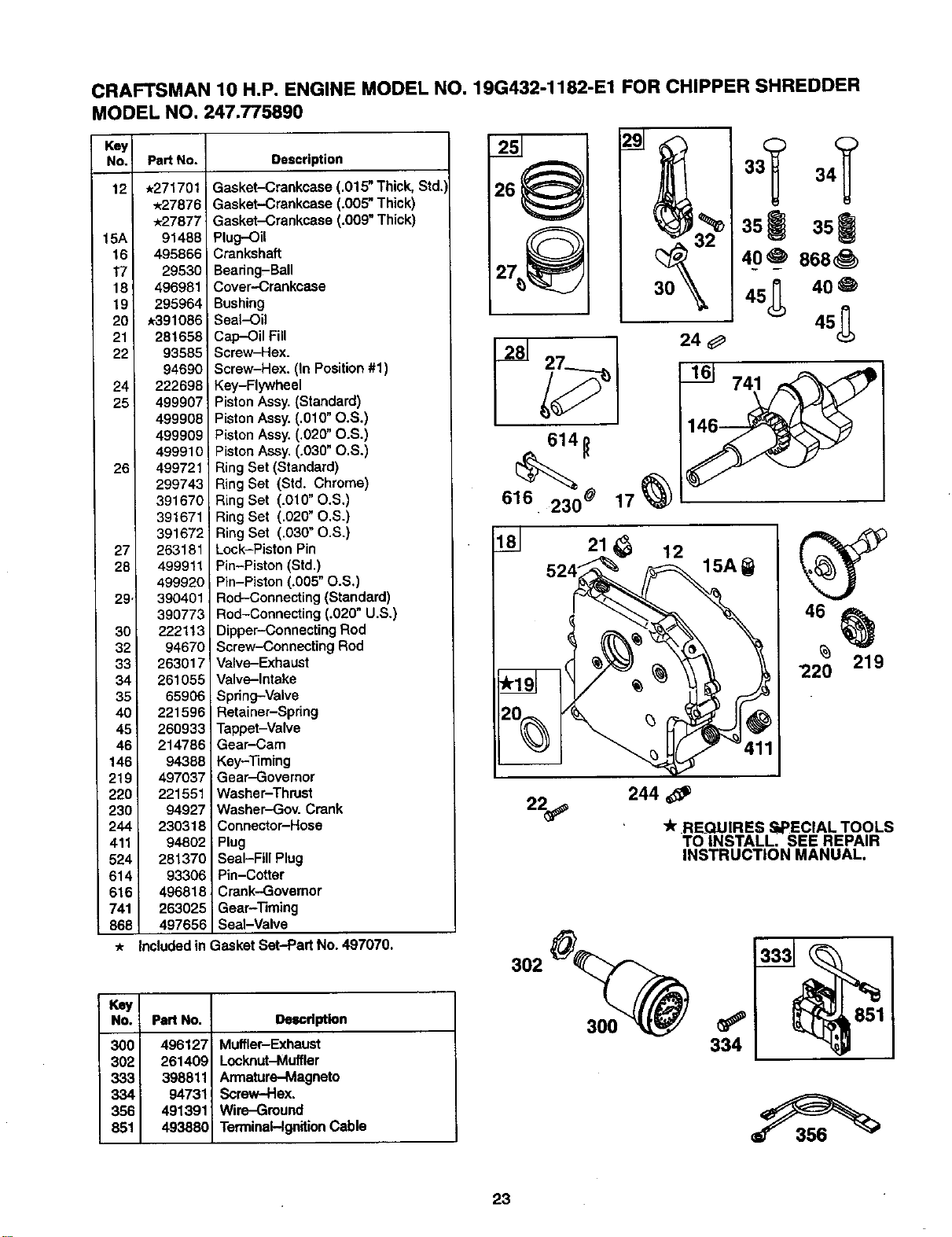
tit REQUIRES SPECIAL TOOLS
TO INSTALL. SEE REPAIR
INSTRUCTION MANUAL.
302
300
334
23
CRAFTSMAN 10 H.P. ENGINE MODEL NO. 19G432*1182-E1 FOR CHIPPER SHREDDER
MODEL NO. 247.775890
Kay
No. Part No.
50
51
51A
53
93
" 94
95
98A
104
105
106
108
123
125
127
130
131
133
137
138
141
142
147
186
634
950
965
975
987
1091
214170
_D,272707
•_?72708
94778
A281346
498836
&94098
495800
tL231789
A231935
_231856
224666
94913
499029
&
224539
497846
494381
t _?.81!65
t t_281164
497160
4498716
499032
232086
493496
A494455
94642
94010
495933
&251166
281364
Description
Manifold-Intake
Gasket]ntake
Gasket-Intake
Stud-Carb. Mounting
Bushing-Throttle Shaft
Valve-Idle Adjust
Screw-Round Head
Screw-Idle Speed
Pin-Float Hinge
Valve-Needle
Seat-inlet
Valve-Choke
Screw-Torx®Hex.
Carburetor
Plug-Welch (Sold in Kit Only)
Valve-Throttle
Shaft-Throttle
Float-Carburetor
Gasket-F]oat Bowl
Washer
Shatt-Choke
Nozzle-Carburetoi_.(Std.)
Nozzle-Carburetor (High AIt.)
Jet-Pilot
Connector-Hose
Seal-Spring Assembly
Screw-Bowl Mounting
Nut-Hex.
Bowl Assembly-Carburetor
Seal-Throttle Shaft
Ca.c-Limiter
Key
No.
55
56
57
58
59
60
63
64
65
66
67
68
70
71
373
6O8
655
1016
Pad No.
393576
295871
490179
66894
490653
490652
26O414
281204
94904
399671
394897
63770
298799
394506
94908
390391
222598
490817
Descdptlon
Housing-Rewind Starter
Pulley-Starter
Spring-Rewind Starter
Rope-Starter
(63" Long)
Insert-Grip
Grip-Starter Rope
Spring-Ratchet
Adapter-Spring
Screw-Hex.
Clutch-Starter
Housing-Clutch
Bali-Clutch
Ratchet-Clutch
Cover-Ratchet
Nut-Hex.
Starter Assy.--RewirK:l
Anchor-Rewind Spring
Spacer-Rewind
* Included in Gasket Sat-Part No. 497070.
O Included in Valve Overhaul Gasket Set-Part
• Included in Carburetor Gasket Set-Part No. 497069.
,_, Included in Carburetor Kit-Part No. 497849.
_12sJ
131
130 _r-
95 987
93
51A
142
lO5 186
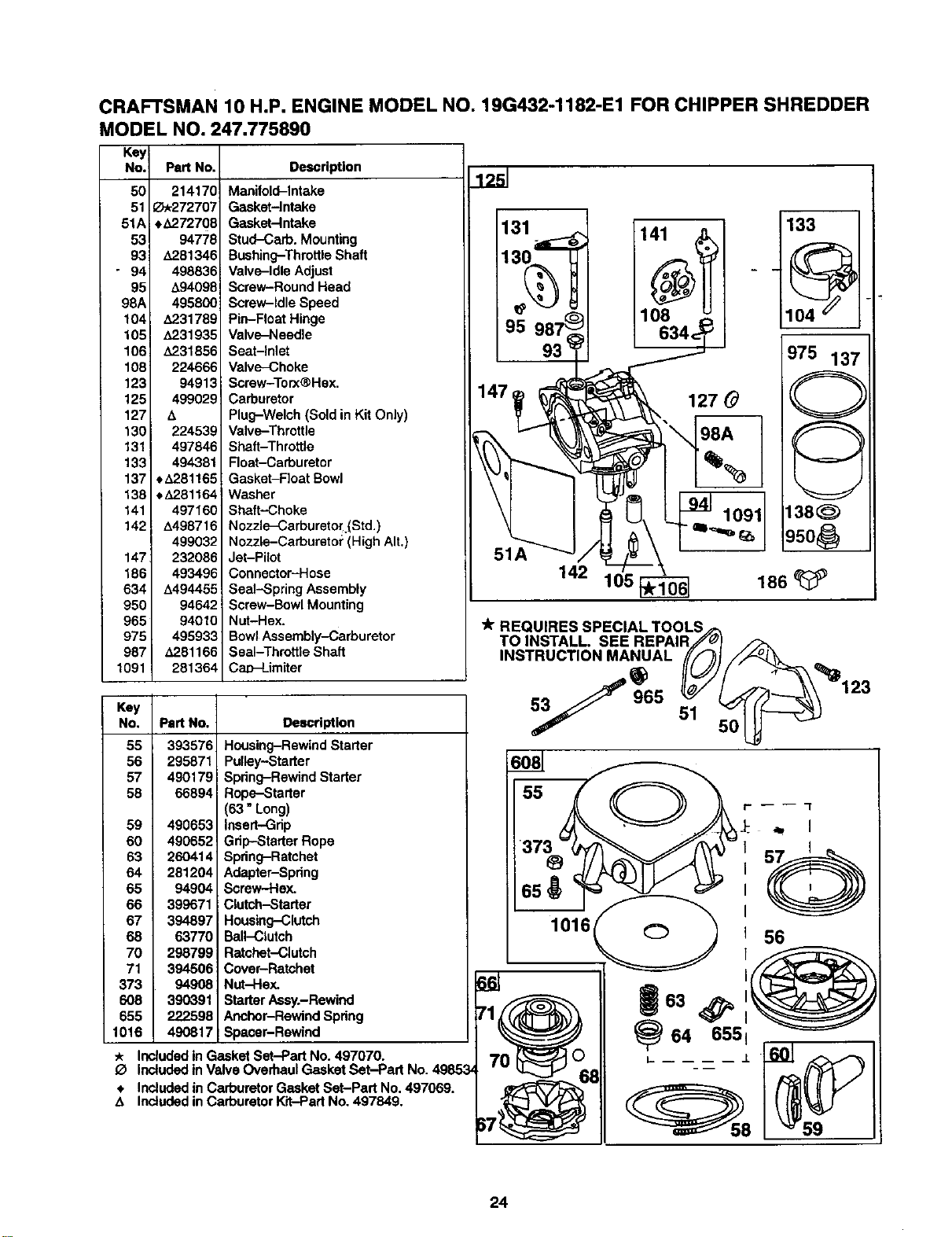
REQUIRES SPECIAL TOOLS/;_
TO INSTALL. SEE REPAIR,fYJ_
INSTRUCTION MANUAL ((,.f_l /_
_64 6551
I- .L
59
24
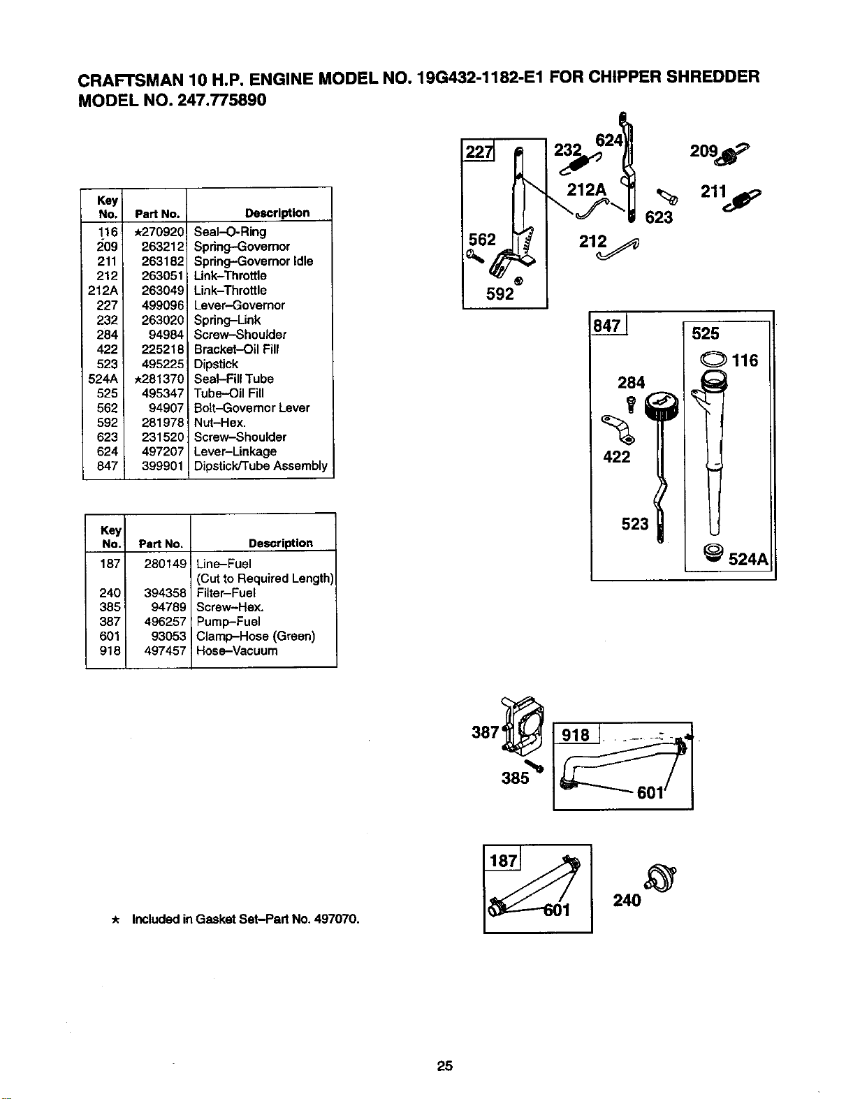
CRAFTSMAN 10 H.P. ENGINE MODEL NO. 19G432-1182-E1 FOR CHIPPER SHREDDER
MODEL NO. 247.775890
Key
No.
116
209
211
212
212A
227
232
284
422
523
524A
525
562
592
623
624
847
Part No. Description
*270920 Seal-O-Ring
263212 Spring-Governor
263182 Spring-Governor Idle
263051 Link-Throttle
263049 Link-Throttle
499096 Lever.-Govemor
263020 Spring-Link
94984 Screw---Shoulder
225218 Bracket-Oil Fill
495225 Dipstick
*281370 Seal-Fill Tube
495347 Tube-Oil Fill
94907 Bolt-Governor Lever
281978 Nut-Hex.
231520 Screw-Shoulder
497207 Lever-Linkage
399901 Dipstick/Tube Assembly
Key
No.
187
240
3851
387
601
918
Part No. Description
280149 Line-Fuel
(Cut to Required Length
394358 Fitter-Fuel
94789 Screw-Hex.
496257 Pump-Fuel
93053 Clamp-Hose (Green)
497457 Hose-Vacuum
592
8471 525
Ol16
284 _!
422
523
_ 524_
* Included in Gasket Set-Part No. 497070.
240
25
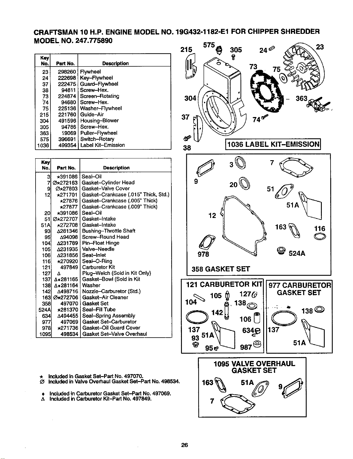
CRAFTSMAN 10 H.P. ENGINE MODEL NO. 19G432-1182-E1 FOR CHIPPER SHREDDER
MODEL NO. 247.775890
Key
No,
23
24
37
38
73
74
75
215
304
305
363
575
1036
Part No. Description
298260 Flywheel
222698 Key-Flywheel
222475 Guard-Flywheel
.94811 Screw-Hex.
224874 Screen-Rotating
94680 Screw-Hex.
225136 Washer-Flywheel
221760 Guide-Air
491596 Housing-Blower
94786 Screw-Hex.
19069 Puller-Flywheel
396691 Switch-Rotary
499354 Label Kit-Emission
215
Key
No. Part No.
3 *391086
7!_,272163
9 _27803
12 *271701
*27876
*27877
20 *391086
51 _272707
51A *272708
93 1_281346
95 A94098
104 A231789
105 A231935
106 A231856
116 *270920
121 497849
127 4
137 4+281165
138 A+281164
142 4498716
163 _-*272706
358 497070
524A *281370
634 4494455
977 497069
978 *271736
1095 498534
Description
Seal-Oil
Gasket-Cylinder Head
Gasket-Valve Cover
Gasket-Crankcase (.015" Thick, Std.)
Gasket-Crankcase (,005" Thick)
Gasket-Crankcase (.009" Thick)
Seal-Oil
Gasket-Intake
Gasket-Intake
Bushing-Throttle Shaft
Screw-Round Head
Pin-Float Hinge
Valve-Needle
Seat-Inlet
Seal--O-Ring
Carburetor Kit
Plug-Welch (Sold in Kit Only)
Gasket-Bowl (Sold in Kit
Washer
Nozzle-Carburetor (Std.)
Gasket-Air Cleaner
Gasket Set
Seal-Fill Tube
Seal-Spring Assembly
Gasket Set-Carburetor
Gasket-Oil Guard Cover
Gasket Set-Valve Overhaul
358 GASKET SET
121 CARBURETOR Kl't"
104_ 105 _ 127_
138
0 142 106_
137 A_ 634_
93 51
95e -_._j 9871_
977 CARBURETOR
GASKET SET
Q 138_)
137 51A_
* Included in Gasket Set-Part No. 497070.
O Included in Valve Overhaul Gasket Set-Part No. 498534.
• IncludedinCarburetorGasketSet-Part No.497069.
A Includedin CarburetorKit-PartNo.497849.
1095 VALVE OVERHAUL
GASKET SET
26

Forthe repairorreplacementpartsyouneed
delivereddirectlyto yourhome
Call7 am - 7 pm,7 daysaweek
1-800-366-PART
(1-800-366-7278)
Forin-homemajorbrandrepairservice
Call24 hoursaday,7 daysaweek
1-8OO-4-REPAIR
(1-800-473-7247)
Forthelocationofa
SearsPartsandRepairCenterinyourarea
Call24 hoursa day,7 daysaweek _
1-800-488-1222
l'--"
mmmmmm
mmmmmm
ForinformationonpurchasingaSears
MaintenanceAgreementorto inquire ___
aboutan existingAgreement
call 9am-5 pm, Monday-Saturday __,_l
1-800-827-6655
SEARS
America'sRepairSpeciatists

