Loading ...
Loading ...
Loading ...
o Mountrearofseatonslidesusingmountingboutsand
bckwashersasshown,
o PuNoutonadjustmenthandbandslideseataHtheway
forward,installfrontmountingboutsandbckwashers,
TightenaHmountingboutssecureUy,
Lowerseatintooperatingpositionandsitonseat,Press
dutch/brakepedaUaHthewaydown,ffoperatingposi-
tionis notcomfortabb,adjustseat,
o Toadjustseat:Graspadjustmenthandbandpunout,
slideseattodesiredpositionandrebaseadjustment
handb,
ADJUSTMENT
LH. SEAT
SUE
SEAT
MOUNTmNG
BOLTS
FIG. 3
Slowly move the motion control lever forward and slowly
drive tractor off skid,
Apply brake to stop tractor, set parking brake and place
motion control lever in neutral position,
Turn ignition key to "STOP" position,
Continue with the instructions that follow,
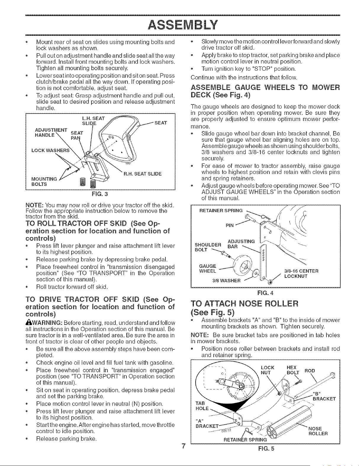
ASSEMBLE GAUGE WHEELS TO MOWER
DECK (See Fig. 4)
The gauge wheels are designed to keep the mower deck
in proper position when operating mower, Be sure they
are properly adjusted to ensure optimum mower perfor-
mance,
Slide gauge wheel bar down into bracket channel, Be
sure that gauge wheel bar aligning hobs are on top,
Assemble gauge wheels as shown using shoulder bolts,
3/8 washers and 3/8-16 center Iocknuts and tighten
securely,
For ease of mower to tractor assembly, raise gauge
wheels to highest position and retain with clevis pins
and spring retainers,
Adjust gauge wheels before operating mower, See "TO
ADJUST GAUGE WHEELS" in the Operation section
of this manual,
TO ROLL TRACTOR OFF SKiD (See Op-
eration section for _ocation and function of
controls)
• Press lift lever plunger and raise attachment lift lever
to its highest position,
• Release parking brake by depressing brake pedal,
• Place freewheel control in "transmission disengaged
position" (See "TO TRANSPORT" in the Operation
section of this manual),
o Roll tractor forward off skid,
TO DRmVE TRACTOR OFF SKID (See Op-
eration section for _ocation and function of
controls)
_WARNING: Before starting, read, understand and follow
all instructions in the Operation section of this manual, Be
sure tractor is in a welPventilated area, Be sure the area in
front of tractor is clear of other people and objects,
• Be sure all the above assembly steps have been com-
pbted,
• Check engine oil level and fill fuel tank with gasoline,
• Place freewheel control in "transmission engaged"
position (see "TO TRANSPORT" in Operation section
of this manual),
o Sit on seat in operating position, depress brake pedal
and set the parking brake,
o Place motion control lever in neutral (N) position,
o Press lift lever plunger and raise attachment lift lever
to its highest position,
o Start the engine,After engine has started, move throttb
Release parking brake,
RETAINER SPRING
PIN
ADJUSTING I
SNOULBEB BAD
BOLT _
GAUGE
WHEEL
3/SWASBEB
318-16 CENTER
_/ LOCKNUT
FIG. 4
TO ATTACH NOSE ROLLER
(See Fig. 5)
Assemble brackets "A" and "B" to the inside of mower
mounting brackets as shown, Tighten securely,
NOTE: Be sure bracket tabs are positioned in tab holes
in mower brackets,
Position nose roller between brackets and install rod
and retainer spring,
LOCK BEX
NUT BOLT ROD
HOLE
RETAINER SPRING
7 FIG. 5
Loading ...
Loading ...
Loading ...