
MS2205
DIGITAL CLAMP METER
OPERATION MANUAL
~
~
kW
1 PHASE
Ø
1 PHASE
kW/Ø
3 PHASE
HARM
A~
V~
HARM
°
APS
RS232
HOLD
REC
FS
LAG
LEAD
RST
CAL
USED
READ
MEMO
COSΦ
SINΦ
MAX MIN
VA
kWh
PEAK
%THD
kVA
Hz
HzA
PEAK
kWVAh
POWER CLAMP METER
MS2205
Yrue RMS
Harmonic
AUTO RANGE
MODE I
U READ
CLEARRS232
Watt
SET
COM/V2
EN61010-1
600V CAT III
V3V1
HOLD
OFF

CONTENTS CONTENTS
Safety Requirements.................................1
Safety Instructions......................................2
Safety Sign...................................................2
General Description....................................2
Features........................................................3
Appearance..................................................4
Knob Switch Operations............................6
B ........................7utton Switch Operations
LCD Display................................................10
I ...................................12nstruction Manual
T .....................................21est Data Storage
Read Saved Data.......................................22
RS232C Data Interface..............................22
Input Voltage and Current........................23
Backlight Display.......................................23
...........................................23Auto Power Off
D ......................24iagram of Safe Holding
Power curve diagram...............................25
Battery-low Indication..............................26
Battery Replacement..............................26
General specification.............................28
T .........................28echnical specification
Accessories .............................................29
..................................31Replacing Test Leads
Replacing The Batteries..............................31

01 02
Please carefully read the instruction manual before
using the tester, and pay special attention to “Warning”
content. Please follow instructions under “Warning”.
1. Please be very careful when test voltage is higher
than AC 30 V, and do keep in mind that your finger
shall not exceed the hand-shielding part of the
test probe.
2. Do not measure voltage which is higher than the
allowed input limit.
3. Before use, please check the meter and test probe;
do not carry out testing in case the test probe is
naked, tester housing is damaged, or there is no
LCD display, etc..
4. It meets requirements of safety standards only when
the meter is used together with the supplied test
probes. In case the test probe is damaged and
needs replacement, it is required to replace it with
a test probe of the same model and identical
electrical specifications.
5. Please never carry out any voltage measurement
whenever the test probe is inserted in any current
outlet.
Safety Instructions
Important safety signs; please refer to
instruction manual
High voltage hazard
Earthing
Double insulation (Category-II safety
equipment)
Battery low Indicator
The three-phase clamp-type digital power meter is
designed and manufactured in accordance with
international standard, IEC61010-1, and international
safety specification, IEC1010-2-032, and the meter
strictly follows the safety standard of double-insulation
AC 600 V CAT III.
6. Please do not expose the meter to strong light, high
temperature, or dampness.
Warning
Before use, please carefully read this instruction
manual.Especially safety contents!
Safety Sign
General Description
The 3-phase clamp-type digital power meter is a hand-
held intelligent harmonic power tester, with both functions
of digital current testing and power testing. The tester is
comprised of three channels including voltage, current,
and power as well as a micro single chip system, and it is
equipped with a powerful software for measurement and
data processing functions; it can measure, calculate,
and display voltage, current, active power, power factor,
apparent power, passive power, frequency, harmonic
Safety Requirements
CAT III (MEASUREMENT CATEGORY III): It is applicable to
test and measuring circuits connected to the distribution part
of the building’s low-voltage MAINS installation.

03 04
clamp structure, small volume, and light weight, it can
be easily carried by the user, which makes it easy and
fast for doing measurement. For measurement of sing-
phase/three-phase power, The meter is your ideal
choice
Features
1.The meter can be used for testing power, voltage,
current, peak value, phase, frequency, power factor,
phase angle, and reaction factor, etc. of single-/
three-phase circuit; automatic phase sequence
testing is possible for 3-phase measurement.
2. True effective value measurement: accurate
measurement is possible even with serious
distortion in current waveform.
3. Low-consumption high-speed single-chip
microprocessor is employed and sophisticated
algorithm is applied, as a result, results can be
obtained rapidly and precisely, and up to 20
harmonics and distortion value thereof can be
measured.
4. It is equipped with a large-size memory for saving
up to 100 groups of test parameters.
5. It is equipped with RS232C communication and
recording interface and dedicated WINDOWS
graphics software.
6. Hand-held, clamp-type structure, with light weight,
convenient for carry-on.
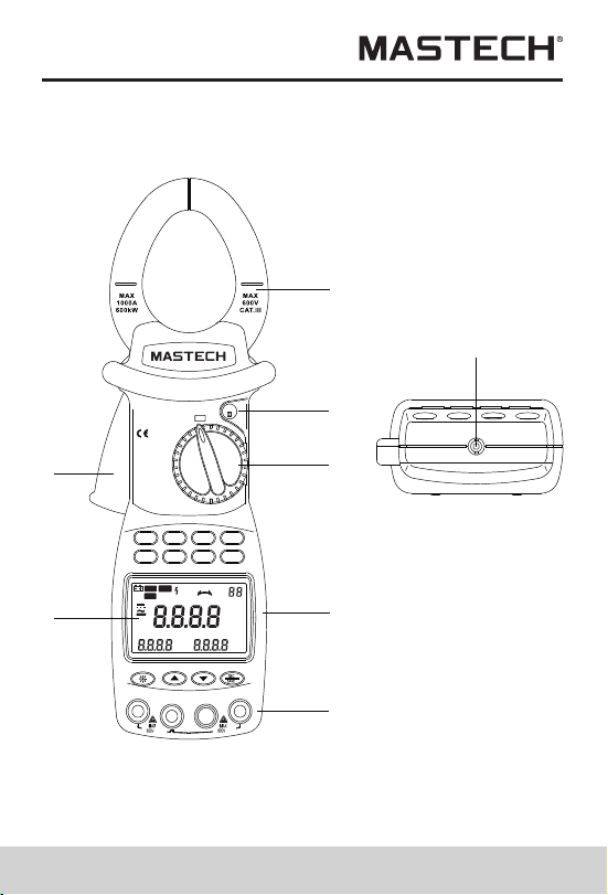
Appearance
1
2
3
4
5
8
6
7
parameters, with stable performance and operation
convenience. The meter is especially suitable for the
measurement and examination of on-site power
equipment and power-supplying circuits; with hand-held
~
~
kW
1 PHASE
Ø
1 PHASE
kW/Ø
3 PHASE
HARM
A~
V~
HARM
°
APS
RS232
HOLD
REC
FS
LAG
LEAD
RST
CAL
USED
READ
MEMO
COSΦ
SINΦ
MAX MIN
VA
kWh
PEAK
%THD
kVA
Hz
HzA
PEAK
kWVAh
POWER CLAMP METER
MS2205
Yrue RMS
Harmonic
AUTO RANGE
MODE I
U READ
CLEARRS232
Watt
SET
COM/V2
EN61010-1
600V CAT III
V3V1
HOLD
OFF
03 04
clamp structure, small volume, and light weight, it can
be easily carried by the user, which makes it easy and
fast for doing measurement. For measurement of sing-
phase/three-phase power, The meter is your ideal
choice
Features
1.The meter can be used for testing power, voltage,
current, peak value, phase, frequency, power factor,
phase angle, and reaction factor, etc. of single-/
three-phase circuit; automatic phase sequence
testing is possible for 3-phase measurement.
2. True effective value measurement: accurate
measurement is possible even with serious
distortion in current waveform.
3. Low-consumption high-speed single-chip
microprocessor is employed and sophisticated
algorithm is applied, as a result, results can be
obtained rapidly and precisely, and up to 20
harmonics and distortion value thereof can be
measured.
4. It is equipped with a large-size memory for saving
up to 100 groups of test parameters.
5. It is equipped with RS232C communication and
recording interface and dedicated WINDOWS
graphics software.
6. Hand-held, clamp-type structure, with light weight,
convenient for carry-on.
Appearance
1
2
3
4
5
8
6
7
parameters, with stable performance and operation
convenience. The meter is especially suitable for the
measurement and examination of on-site power
equipment and power-supplying circuits; with hand-held
~
~
kW
1 PHASE
Ø
1 PHASE
kW/Ø
3 PHASE
HARM
A~
V~
HARM
°
APS
RS232
HOLD
REC
FS
LAG
LEAD
RST
CAL
USED
READ
MEMO
COSΦ
SINΦ
MAX MIN
VA
kWh
PEAK
%THD
kVA
Hz
HzA
PEAK
kWVAh
POWER CLAMP METER
MS2205
Yrue RMS
Harmonic
AUTO RANGE
MODE I
U READ
CLEARRS232
Watt
SET
COM/V2
EN61010-1
600V CAT III
V3V1
HOLD
OFF

Input terminal for measuring the first
phase; use yellow test probe for
connection.
Input terminal for measuring the 2nd
phase; use black test probe for connection.
Common terminal: ground input terminal
(earthing) for all measuring functions; use
black test probe for connection.
Function
Terminal
V1
COM/V2
V3
Input terminal for measuring the 3rd
phase; use green test probe for
connection.
05 06
1. Current clamp size: Φ 50 mm
2. HOLD button :DATA HOLD button; press down
HOLD button, and the last reading will be held and
displayed on the display, and “HOLD” symbol will be
shown; press HOLD button again, and the meter will
switch back to normal measurement mode.
3. Function-switching knob :Rotation knob for selecting
different measuring function
4. Function-selection button: Button for operating the
measuring functions
5. Input terminal
6. LCD display :4-digit digital display; 7-section LCD
for displaying measurement operation function, test
result, and unit sign.
7. Trigger :Press down the trigger, and the clamp will
open; release it, and the clamp will close.
8. RS232C interface: Dedicated optical-electrical
interface wire is used for online communication with
PC, as well as for recording data and data trend curve
in PC.
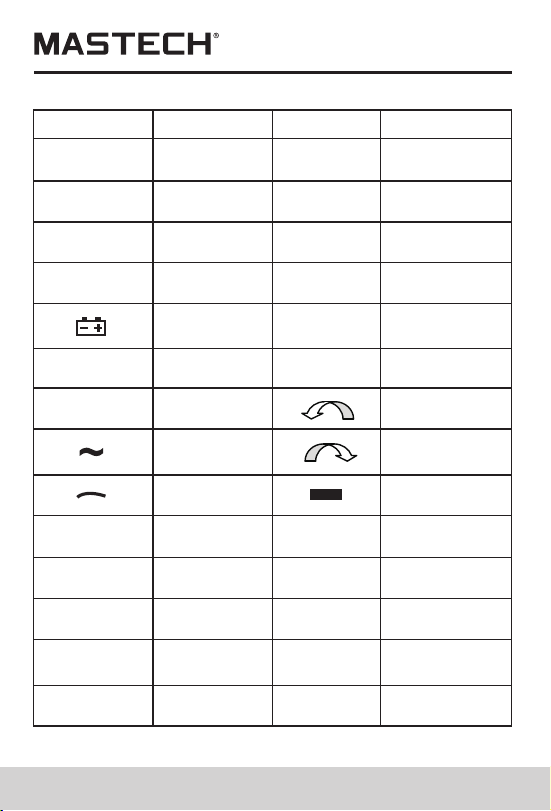
Knob Switch Operations
The function-switching knob is used for powering-on and
for switching to any measurement function in the
following table.
Note:
When the meter is automatically powered off, be sure to
switch the knob to “OFF” position; turn on the meter after
5 seconds.
For measuring
active power, etc.
For measuring phase
angle, such as cos Φ
and sin Φ, etc.
For powering-offPowering-off position
Sign
Knob position
Functions
OFF
Active power position
(1 phase)
Single-phase/phase-
angle Test position
For measuring 3-
phase apparent
power, etc.
For measuring
AC-current
harmonics, etc.
For measuring
AC-Voltage
harmonics, etc.
AC-voltage
harmonics test
position
AC-Current
harmonics test
position
3-phase apparent
power position
KW/Φ
(3 phase)
A
KW
Φ
(1 phase)
V
Input terminal for measuring the first
phase; use yellow test probe for
connection.
Input terminal for measuring the 2nd
phase; use black test probe for connection.
Common terminal: ground input terminal
(earthing) for all measuring functions; use
black test probe for connection.
Function
Terminal
V1
COM/V2
V3
Input terminal for measuring the 3rd
phase; use green test probe for
connection.
05 06
1. Current clamp size: Φ 50 mm
2. HOLD button :DATA HOLD button; press down
HOLD button, and the last reading will be held and
displayed on the display, and “HOLD” symbol will be
shown; press HOLD button again, and the meter will
switch back to normal measurement mode.
3. Function-switching knob :Rotation knob for selecting
different measuring function
4. Function-selection button: Button for operating the
measuring functions
5. Input terminal
6. LCD display :4-digit digital display; 7-section LCD
for displaying measurement operation function, test
result, and unit sign.
7. Trigger :Press down the trigger, and the clamp will
open; release it, and the clamp will close.
8. RS232C interface: Dedicated optical-electrical
interface wire is used for online communication with
PC, as well as for recording data and data trend curve
in PC.
Knob Switch Operations
The function-switching knob is used for powering-on and
for switching to any measurement function in the
following table.
Note:
When the meter is automatically powered off, be sure to
switch the knob to “OFF” position; turn on the meter after
5 seconds.
For measuring
active power, etc.
For measuring phase
angle, such as cos Φ
and sin Φ, etc.
For powering-offPowering-off position
Sign
Knob position
Functions
OFF
Active power position
(1 phase)
Single-phase/phase-
angle Test position
For measuring 3-
phase apparent
power, etc.
For measuring
AC-current
harmonics, etc.
For measuring
AC-Voltage
harmonics, etc.
AC-voltage
harmonics test
position
AC-Current
harmonics test
position
3-phase apparent
power position
KW/Φ
(3 phase)
A
KW
Φ
(1 phase)
V
07 08
Under KW-test mode, you can press MODE button to
switch the display of active power and passive power;
under A/V~ test mode, you can switch the display among
total harmonic distortion rate F, r, and harmonic
percentage.
SET Button
Under test mode, you can press SET button and then
press and button to set the range of current and
voltage, and then press this button again to return. This
button serves as CONFIRMATION button during storage
and deleting.
U Button
Under test mode, you can press this button to test
voltage of the present circuit, and display the measured
voltage of the present circuit on display.
READ Button
Under HOLD mode, you can press this button to display
the stored data; press this button again to return.
I Button
Under test mode, you can press I button to measure
current of the present circuit and display the measured
current of the circuit by the clamp on LCD.
RS232 Button
Under test mode, you can press RS232 button to transfer
the present test result to PC through a dedicated
interface wire supplied for the meter so as to record/print
data and data trend graph.
Button Switch Operations
Button descriptions
Function-selection button
MODE :Test-mode switching button
SN
1
2
3
4
SET SET button :
I Current test button :
WATT Power test switching button :
5 U Voltage test button :
6 READ Data-Reading button :
7 RS232 RS232C button :
8 CLEAR Clear memory button :
9 Backlight button
10
Reverse-search button
11 Forward-search button
12 REC/SAVE Data recording & storage button
13 HOLD Hold button
The following functions can be realized through button
operations:
WATT Button
Under test mode, you can measure active power,
apparent power, power factor, and phase angle and
display the results on LCD by pressing WATT button.
MODE Button

09 10
Before pressing RS232 button for data transferring,
the supplied RS232C interface wire shall be
connected to RS232C interface socket of the meter
and PC COM port, before realizing communication
functions.
CLEAR Button
Under data-reading mode, you can press CLEAR
button and then press SET button to clear the test data
which is stored in the meter under a specified number.
Button
You can press button to turn on or off the backlight.
After it is turned on for 20 seconds, the backlight will
automatically be turned off.
Button
Under VOLTAGE-RANGE-SETUP mode, you can
press button to changethe voltage test range.
During testing harmonics, you can change the times
of harmonics.
When reading the saved data, you can press button
to search backward thestored data and show it on
LCD. With every press of the button, the
searchingcursor will move one step backward to the
previous data.
Button
Under CURRENT-RANGE-SETUP mode, you can
press button to change current test range. During
testing harmonics, you can change the times of
harmonics.
When reading the saved data, you can press button
to search in the forward direction the stored data and
show it on LCD. With every press of the button, the
searching cursor will move one step forward to the
next data
REC/SAVE Button
Under TEST mode, you can press REC/SAVE button to
display the max. /min. power, current, voltage that is
currently measured; under DATA HOLD mode, press this
button to display the stored number; press SET button
again to save the held data in the meter. Up to 100
groups of data can be stored in the meter.
HOLD Button
After measurement, press this button to hold this data on
LCD; after powering-off, data will display.
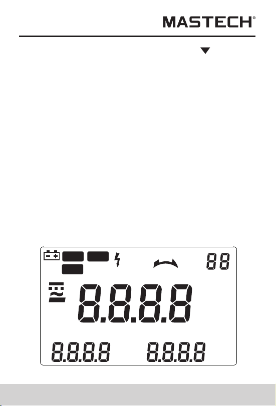
LCD Display
°
APS
RS232
HOLD
REC
FS
LAG
LEAD
RST
CAL
USED
READ
MEMO
COSΦ
SINΦ
MAX MIN
VA
kWh
PEAK
%THD
kVA
Hz
HzA
PEAK
kWVAh
09 10
Before pressing RS232 button for data transferring,
the supplied RS232C interface wire shall be
connected to RS232C interface socket of the meter
and PC COM port, before realizing communication
functions.
CLEAR Button
Under data-reading mode, you can press CLEAR
button and then press SET button to clear the test data
which is stored in the meter under a specified number.
Button
You can press button to turn on or off the backlight.
After it is turned on for 20 seconds, the backlight will
automatically be turned off.
Button
Under VOLTAGE-RANGE-SETUP mode, you can
press button to changethe voltage test range.
During testing harmonics, you can change the times
of harmonics.
When reading the saved data, you can press button
to search backward thestored data and show it on
LCD. With every press of the button, the
searchingcursor will move one step backward to the
previous data.
Button
Under CURRENT-RANGE-SETUP mode, you can
press button to change current test range. During
testing harmonics, you can change the times of
harmonics.
When reading the saved data, you can press button
to search in the forward direction the stored data and
show it on LCD. With every press of the button, the
searching cursor will move one step forward to the
next data
REC/SAVE Button
Under TEST mode, you can press REC/SAVE button to
display the max. /min. power, current, voltage that is
currently measured; under DATA HOLD mode, press this
button to display the stored number; press SET button
again to save the held data in the meter. Up to 100
groups of data can be stored in the meter.
HOLD Button
After measurement, press this button to hold this data on
LCD; after powering-off, data will display.
LCD Display
°
APS
RS232
HOLD
REC
FS
LAG
LEAD
RST
CAL
USED
READ
MEMO
COSΦ
SINΦ
MAX MIN
VA
kWh
PEAK
%THD
kVA
Hz
HzA
PEAK
kWVAh
12
LCD symbol
Description
LCD symbol
Description
Total harmonics distortion ratio
Total harmonics distortion ratio F
(relative to base wave)
Total harmonics distortion ratio r
(relative to real effective value)
H01r
H01F
%THD
Instruction Manual
AC voltage (V) measurement
ACV
Description
LCD symbol
Data transfer
REC
F
Auto
powering-off
Data holding
S
Phase angle
lag
LEAD
Battery power
indication
O
Reversed
power factor
3-phase
AC symbol
Phase
lacking
MAX
MEMO
COSФ
Description
Data
recording
Fast
Slow
Phase angle
lead
Phase angle
(degree)
Power factor
Normal
phase
Reversed
phase
Negative
symbol
Maximum
value
Save
Voltage
Current
Frequency
LCD symbol
RST
MIN
USED
SINΦ
LAG
APS
RS232
HOLD
W
READ
VAr
V
A
Hz
Minimum
value
Used
Read
Watt
Passive
power
11
PEAK
Peak value
VA
Apparent
power
High-voltage
warning sign
%
Harmonic
percentage
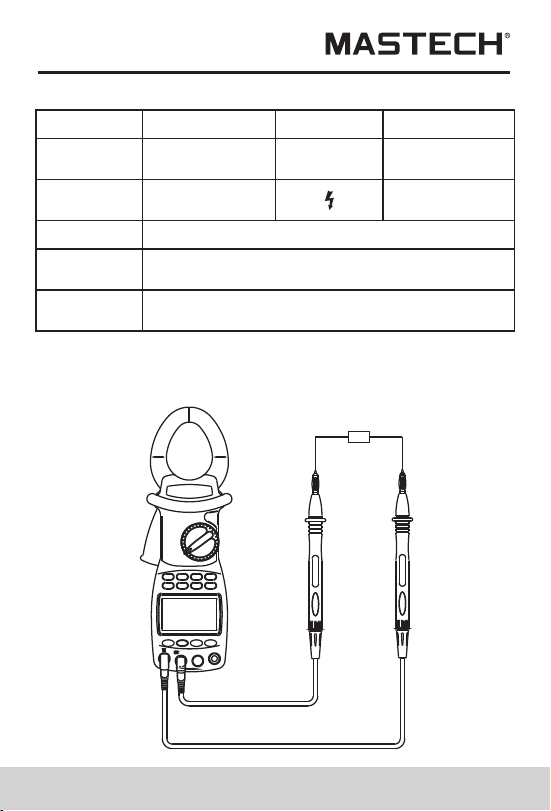
Switch
Inputting
terminal V1
Inputting
terminal V2
Inputting
terminal V3
Test object
V~
V1 socket
COM/ V2
socket
COM/ V2
socket
COM/ V2
socket
N/A
N/A
V3 socket
1-phase
2-phase
3-phase
13 14
1.According to the connection mode as above Table ,
switch the function switching knob to V~, select
corresponding sockets from V1, V2, or V3 terminal,
and insert the test wire.
2.Connect the two test probes V1, V2 to the power
source or load to be tested. The meter will automatically
test and display the result, and the present harmonics
percentage will be shown on the following line.
3.Under voltage test mode, press SET button to show
”Auto V” and “Auto A” on LCD, and press to select a
proper voltage range, and then press SET to return.
4.Press MODE button to show harmonics percentage
on LCD, and the total harmonic distortion ratio F and R
will be cyclically displayed. Press / button to
display value of each measurement of the harmonic.
5.When input voltage is greater than 50 V, “ ” sign
will be shown on LCD, prompting you to pay attention
to safety.
AC-current (A) measurement
V1 socket
V1 socket
NEUTRAL
3
2
1

15 16
1.Switch the function knob to A~ position;
2.Pull the trigger to open the clamp, and then clip a
wire which is to be tested; the measured current
value will be automatically shown on LCD
3.Press MODE button to show harmonics percentage
on LCD, and the total harmonic distortion ratio F and
r will be cyclically displayed.
4.Press ▲/▼ button to display value of each
measurement of the harmonic.
If current of the wire being tested is greater than
1000 A (RMS), ”OL” symbol will be displayed instead
of current value.
Note:
1.You can select 50/60-Hz FIXED/AUTO frequency
test (AUTO). When input waveform fluctuates,
displayed harmonic values can be kept stable if
50/60-Hz FIXED mode is selected.
2. Under AUTO frequency test mode, FFT calculation
is performed only when base-wave frequency is
between 45 and 65 Hz; harmonic analysis is not
performed when base-wave frequency exceeds
this range.
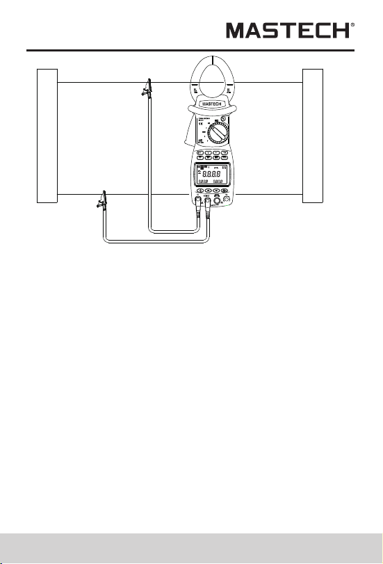
Test of single-phase circuit
1.Clip the clamp on the test wire of the power supply
or load. If the user needs to measure a certain phase
of the 3-phase circuit, then the clamp should clip on
the wire of the same phase.
2.switch the function switching knob to KW position,
select corresponding input sockets from V1 or V2
terminal and insert the test wire.
3. After it is correctly connected, you can measure single-
phase power (active power, power factor, apparent
power, passive power, voltage, current, phase angle,
peak value of voltage and current, and frequency):
4. The meter will carry out automatic measurement and
display active power, and voltage/current value of the
load being tested will be displayed on the bottom line
of LCD; press down MODE button, Var value of
passive power will be displayed on LCD; press WATT
button to display apparent power and power factor
(cos Φ); negative power factor signifies that the load
being tested is a load with capacitor characteristics.
5. The maximum measurement range of active power kW
is 600 kW; if this range is exceeded, “OL” symbol will
be displayed beyond this range. If voltage being
tested is greater than 600 V, or current being tested
greater than 1000 A, “OL” symbol will be displayed
on LCD.
°
APS
RS232
HOLD
REC
FS
LAG
LEAD
RST
CAL
USED
READ
MEMO
COSΦ
SINΦ
MAX MIN
VA
kWh
PEAK
%THD
kVA
Hz
HzA
PEAK
kWVAh
~
3 PHASE
1PHASE
1PHASE
HARM
HARM
Power supply side
Load
Yellow
Black
600V~
MAX
600V~
MAX
~
15 16
1.Switch the function knob to A~ position;
2.Pull the trigger to open the clamp, and then clip a
wire which is to be tested; the measured current
value will be automatically shown on LCD
3.Press MODE button to show harmonics percentage
on LCD, and the total harmonic distortion ratio F and
r will be cyclically displayed.
4.Press ▲/▼ button to display value of each
measurement of the harmonic.
If current of the wire being tested is greater than
1000 A (RMS), ”OL” symbol will be displayed instead
of current value.
Note:
1.You can select 50/60-Hz FIXED/AUTO frequency
test (AUTO). When input waveform fluctuates,
displayed harmonic values can be kept stable if
50/60-Hz FIXED mode is selected.
2. Under AUTO frequency test mode, FFT calculation
is performed only when base-wave frequency is
between 45 and 65 Hz; harmonic analysis is not
performed when base-wave frequency exceeds
this range.
Test of single-phase circuit
1.Clip the clamp on the test wire of the power supply
or load. If the user needs to measure a certain phase
of the 3-phase circuit, then the clamp should clip on
the wire of the same phase.
2.switch the function switching knob to KW position,
select corresponding input sockets from V1 or V2
terminal and insert the test wire.
3. After it is correctly connected, you can measure single-
phase power (active power, power factor, apparent
power, passive power, voltage, current, phase angle,
peak value of voltage and current, and frequency):
4. The meter will carry out automatic measurement and
display active power, and voltage/current value of the
load being tested will be displayed on the bottom line
of LCD; press down MODE button, Var value of
passive power will be displayed on LCD; press WATT
button to display apparent power and power factor
(cos Φ); negative power factor signifies that the load
being tested is a load with capacitor characteristics.
5. The maximum measurement range of active power kW
is 600 kW; if this range is exceeded, “OL” symbol will
be displayed beyond this range. If voltage being
tested is greater than 600 V, or current being tested
greater than 1000 A, “OL” symbol will be displayed
on LCD.
°
APS
RS232
HOLD
REC
FS
LAG
LEAD
RST
CAL
USED
READ
MEMO
COSΦ
SINΦ
MAX MIN
VA
kWh
PEAK
%THD
kVA
Hz
HzA
PEAK
kWVAh
~
3 PHASE
1PHASE
1PHASE
HARM
HARM
Power supply side
Load
Yellow
Black
600V~
MAX
600V~
MAX
~

17 18
6.The min. input voltage is 50 V and the min. input
current is 2A; if active power value is smaller than
this limit, “0.00 kW” will be displayed in stead of
active power value.
7. Press SET button to display AUTO, and press ▲/▼
button to set measurement range for voltage and
current; press SET button to return.
8. Press down I button, current value, current peak
value and frequency will be displayed on bottom line
of LCD.
9. Press down U button, voltage value, voltage peak
value and frequency will be displayed on bottom line
of LCD.
10.Press REC/SAVE button to show MAX and MIN
Passive power is a value not directly measured;
equation for kVAr is kVAr2=kVA2-kW2; its value is
calculated by software based on the measured
voltage, current and active power, and displayed
on LCD.
11.
cosΦ, sinΦ, and phase angle measurement
1.Switch the function-switch knob to Φ (1 phase)
position, and the test wire is inserted to V1/V2 input
terminals.
2.The meter will automatically measure and display
power factor, voltage value and current value.
3.Press WATT button to display phase angle, power
factor (cos Φ), and sinΦ; negative power factor
signifies that the load being tested is a load with
capacitor characteristics.
4.Press down I button, current value, current peak
value and frequency will be displayed on bottom
line of LCD.
5.Press down U button, voltage value, voltage peak value
and frequency will be displayed on bottom line of LCD.
6.Press REC/SAVE button to show MAX and MIN
7.Press SET button to display AUTO, and press /
button to set measurement range for voltage and
current; press SET button to return.
8.After measuring, press HOLD button to keep showing
the data on LCD, and press REC/SAVE button to
display the saved serial number, and then press SET
button to confirm it and return.
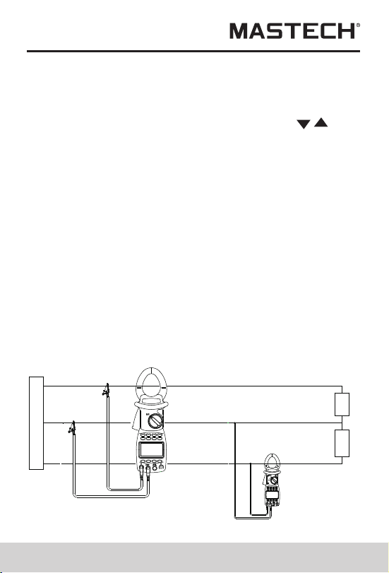
Single-phase three-line circuit
the process for measuring power and power factor for
single-phase three-line circuit is the same as that for
single-phase two-line circuit, where the black clip is
connected to the middle wire, and the red clip and
clamp-type sensor are simultaneously connected to all
test wires.
Power supply side
Red
Black
Load
3 PHASE
1PHASE
1PHASE
HARM
Black
Red
1PHASE
17 18
6.The min. input voltage is 50 V and the min. input
current is 2A; if active power value is smaller than
this limit, “0.00 kW” will be displayed in stead of
active power value.
7. Press SET button to display AUTO, and press ▲/▼
button to set measurement range for voltage and
current; press SET button to return.
8. Press down I button, current value, current peak
value and frequency will be displayed on bottom line
of LCD.
9. Press down U button, voltage value, voltage peak
value and frequency will be displayed on bottom line
of LCD.
10.Press REC/SAVE button to show MAX and MIN
Passive power is a value not directly measured;
equation for kVAr is kVAr2=kVA2-kW2; its value is
calculated by software based on the measured
voltage, current and active power, and displayed
on LCD.
11.
cosΦ, sinΦ, and phase angle measurement
1.Switch the function-switch knob to Φ (1 phase)
position, and the test wire is inserted to V1/V2 input
terminals.
2.The meter will automatically measure and display
power factor, voltage value and current value.
3.Press WATT button to display phase angle, power
factor (cos Φ), and sinΦ; negative power factor
signifies that the load being tested is a load with
capacitor characteristics.
4.Press down I button, current value, current peak
value and frequency will be displayed on bottom
line of LCD.
5.Press down U button, voltage value, voltage peak value
and frequency will be displayed on bottom line of LCD.
6.Press REC/SAVE button to show MAX and MIN
7.Press SET button to display AUTO, and press /
button to set measurement range for voltage and
current; press SET button to return.
8.After measuring, press HOLD button to keep showing
the data on LCD, and press REC/SAVE button to
display the saved serial number, and then press SET
button to confirm it and return.
Single-phase three-line circuit
the process for measuring power and power factor for
single-phase three-line circuit is the same as that for
single-phase two-line circuit, where the black clip is
connected to the middle wire, and the red clip and
clamp-type sensor are simultaneously connected to all
test wires.
Power supply side
Red
Black
Load
3 PHASE
1PHASE
1PHASE
HARM
Black
Red
1PHASE

19 20
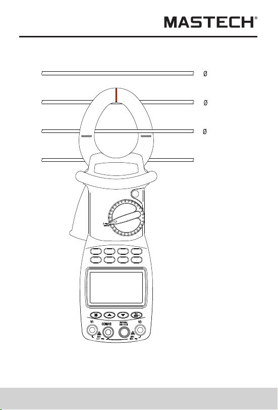
1.In the case of balanced load, process for measuring
power and power factor of 3-phase 4-line circuit is
the same as that for 3-phase 3-line circuit, and it is
not needed to use the middle line.
3-phase total power parameters are referred to as
total active power, total passive power, total
apparent power, and total power factor of 3-phase
circuit. The meter cannot carry out 3-phase energy
measurement. In the case of balanced load,
measured result is accurate, while error of total power
will increase if power variation is large.
2.
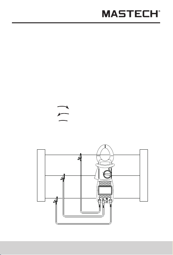
Measuring power of 3-phase load
(for balanced load)
3.switch function-switching knob to kW/Φ (3 phase)
position, and connect test clamp to phase-1 test wire
of the load, and then connect V1 terminal / yellow
test probe, V2 terminal / black test probe, and V3
terminal / green test probe to the live line of phase 1,
phase 2, and phase 3, respectively, of the 3-phase
load without connecting the netural line.
4.After the test lines are properly connected, the meter
will automatically perform measurement and display
power, voltage, current, and whether a phase
is missing.
5.Press MODE button to display Var value of passive
power on LCD.
6.Press WATT button to display apparent power, power
factor (cos Φ), phase angle, and sinΦ; negative
power factor signifies that the load being tested is of
capacitor characteristics.
7.Press down I button, and current value, current peak
value and frequency will be displayed on LCD.
8.Press down U button, and voltage value, voltage
peak value and frequency will be displayed on LCD.
9.Press SET button to display AUTO, and press ▲/▼
button to set the measuring range for voltage and
current, and then press SET button to return.
10.After measuring, press HOLD button to keep
showing the data on LCD, and press RES/SAVE
button to display the saved serial number, and then
press SET button to confirm it and return.
Phase sequence test
1.the meter will automatically test the phase sequence.
2.The display of
RST
RST
signifies normal phase sequence.
3.The display of
4.The display of
RST
signifies reversed phase sequence.
signifies missing phase.
5.During measurement, press REC/SAVE button to show
MAX and MIN and record the results. Then, press REC/
SAVE button to transfer the test result to PC through
infrared communication wire.
1PHASE
Power supply side
Load
Red
Yellow
Black
Measurement of power and power
factor of 3
-
phase 3
-
line circuit
19 20
1.In the case of balanced load, process for measuring
power and power factor of 3-phase 4-line circuit is
the same as that for 3-phase 3-line circuit, and it is
not needed to use the middle line.
3-phase total power parameters are referred to as
total active power, total passive power, total
apparent power, and total power factor of 3-phase
circuit. The meter cannot carry out 3-phase energy
measurement. In the case of balanced load,
measured result is accurate, while error of total power
will increase if power variation is large.
2.
Measuring power of 3-phase load
(for balanced load)
3.switch function-switching knob to kW/Φ (3 phase)
position, and connect test clamp to phase-1 test wire
of the load, and then connect V1 terminal / yellow
test probe, V2 terminal / black test probe, and V3
terminal / green test probe to the live line of phase 1,
phase 2, and phase 3, respectively, of the 3-phase
load without connecting the netural line.
4.After the test lines are properly connected, the meter
will automatically perform measurement and display
power, voltage, current, and whether a phase
is missing.
5.Press MODE button to display Var value of passive
power on LCD.
6.Press WATT button to display apparent power, power
factor (cos Φ), phase angle, and sinΦ; negative
power factor signifies that the load being tested is of
capacitor characteristics.
7.Press down I button, and current value, current peak
value and frequency will be displayed on LCD.
8.Press down U button, and voltage value, voltage
peak value and frequency will be displayed on LCD.
9.Press SET button to display AUTO, and press ▲/▼
button to set the measuring range for voltage and
current, and then press SET button to return.
10.After measuring, press HOLD button to keep
showing the data on LCD, and press RES/SAVE
button to display the saved serial number, and then
press SET button to confirm it and return.
Phase sequence test
1.the meter will automatically test the phase sequence.
2.The display of
RST
RST
signifies normal phase sequence.
3.The display of
4.The display of
RST
signifies reversed phase sequence.
signifies missing phase.
5.During measurement, press REC/SAVE button to show
MAX and MIN and record the results. Then, press REC/
SAVE button to transfer the test result to PC through
infrared communication wire.
1PHASE
Power supply side
Load
Red
Yellow
Black
Measurement of power and power
factor of 3
-
phase 3
-
line circuit
Power supply side
Load
Red
Yellow
Black
Black
Red
Yellow
Yellow
Black
Red
1PHASE
1PHASE
1PHASE
Measurement of power and power factor
21 22
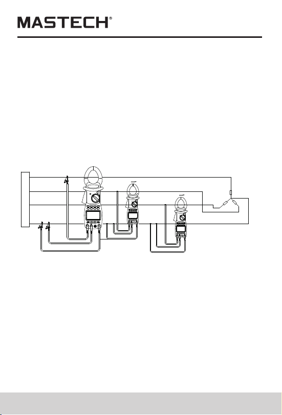
Measuring power of 3-phase 4-line load
(for imbalanced load)
1.When any data is saved in the meter, you can switch it
to READ SAVED DATA position for data retrieving.
2.Switch function-switching knob to SEARCH position
and press HOLD button to display HOLD.
In the case of imbalanced load, the measuring process
is the same as that of 1-phase 2-line system, and the
measuring mode is set as 1-phase mode. connect the
black clip to the middle line, and then simultaneously
switch the yellow clip and clamp sensor to
corresponding wires; under this mode, power and power
factor of each line can be tested. (To test phase
sequence, connect voltage clips to the three lines one
by one, with the middle line not connected)
of 3-phase 4-line circuit
Test Data Storage
When the meter is under HOLD mode, you can press
REC/SAVE button to display the serial number to be
saved and press ▲/▼ button to select serial number,
and then press SET button to confirm saving. Test
results are saved in the meter, and up to 100 groups of
data can be saved in the meter.
Before pressing SET button, if you press REC/SAVE
button to quit saving, data will not be saved, and it will
return to the previous menu.
Read Saved Data
3.Press READ button to show the saved serial number
and data on LCD.
4.If you need to check the records stored previously or
afterwards or harmonic level, press ▲/▼button to
make selections.
5.when harmonic level data is displayed , press watt
button, thenpress ▲/▼button to select record number.
6.To delete data, just press CLEAR button, and CLR will
be displayed; then, press SET button to confirm it, and
data will be deleted. Before pressing SET button, if you
press CLEAR button, data will not be deleted, and it
will return to the previous menu.
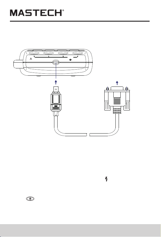
RS232C Data Interface
1.Insert RS232C interface wire into the socket on the
meter, and rotate interface wire clock-wise to lock the
wire in the power meter; connect the standard RS232C
plug on the other end of the interface wire to PC COM
port, and now real-time data transferring with PC can
be realized through the infrared communication
RS232C interface. If you wish to unplug the RS232C
interface wire from the power meter, firstly, rotate the
interface-wire plug in the meter counter-clockwise,
then, take it out after the interface wire is unlocked.
2.If you press RS232 button, the currently measured data
can be recorded in real time under WINDOWS;
3.If you press HOLD button, and then READ button, and
then RS232 button, the saved data can be uploaded

Power supply side
Load
Red
Yellow
Black
Black
Red
Yellow
Yellow
Black
Red
1PHASE
1PHASE
1PHASE
Measurement of power and power factor
21 22
Measuring power of 3-phase 4-line load
(for imbalanced load)
1.When any data is saved in the meter, you can switch it
to READ SAVED DATA position for data retrieving.
2.Switch function-switching knob to SEARCH position
and press HOLD button to display HOLD.
In the case of imbalanced load, the measuring process
is the same as that of 1-phase 2-line system, and the
measuring mode is set as 1-phase mode. connect the
black clip to the middle line, and then simultaneously
switch the yellow clip and clamp sensor to
corresponding wires; under this mode, power and power
factor of each line can be tested. (To test phase
sequence, connect voltage clips to the three lines one
by one, with the middle line not connected)
of 3-phase 4-line circuit
Test Data Storage
When the meter is under HOLD mode, you can press
REC/SAVE button to display the serial number to be
saved and press ▲/▼ button to select serial number,
and then press SET button to confirm saving. Test
results are saved in the meter, and up to 100 groups of
data can be saved in the meter.
Before pressing SET button, if you press REC/SAVE
button to quit saving, data will not be saved, and it will
return to the previous menu.
Read Saved Data
3.Press READ button to show the saved serial number
and data on LCD.
4.If you need to check the records stored previously or
afterwards or harmonic level, press ▲/▼button to
make selections.
5.when harmonic level data is displayed , press watt
button, thenpress ▲/▼button to select record number.
6.To delete data, just press CLEAR button, and CLR will
be displayed; then, press SET button to confirm it, and
data will be deleted. Before pressing SET button, if you
press CLEAR button, data will not be deleted, and it
will return to the previous menu.
RS232C Data Interface
1.Insert RS232C interface wire into the socket on the
meter, and rotate interface wire clock-wise to lock the
wire in the power meter; connect the standard RS232C
plug on the other end of the interface wire to PC COM
port, and now real-time data transferring with PC can
be realized through the infrared communication
RS232C interface. If you wish to unplug the RS232C
interface wire from the power meter, firstly, rotate the
interface-wire plug in the meter counter-clockwise,
then, take it out after the interface wire is unlocked.
2.If you press RS232 button, the currently measured data
can be recorded in real time under WINDOWS;
3.If you press HOLD button, and then READ button, and
then RS232 button, the saved data can be uploaded
23
to PC.
4.This software can be used for managing real-time
data records, plotting, and printing output, etc..
RS232
-C
INTERF
ACE
OPTICAL
600V
MAX
~
3
RS232OPTICAL INTERFACE
计算机
PC COM
(RS232C connection diagram)
Input Voltage and Current
During power measurement, if input voltage is over
600 V (RMS) or current over 1000 A (RMS), “OL”
symbol will be displayed and bar symbol shown in full
scale. When input voltage is over 50 V, “ ” sign will be
shown on LCD, prompting you to pay attention to safety.
Backlight Display
Press
, the backlight will be lit up, and it will then be
automatically turned off after about 20 seconds.
Auto Power Off
24
1.If there is no function change or button press fo 10
minutes ,the meter will automatically turn power off ,
When the meter is automatically powered off, be sure
to switch the knob to “OFF” position; turn on the meter
after 5 seconds.
2.Holding the button SET&CLEAR down while turning
the meter on,Disables automatic power -off
3.automatically powered off function will be disabled
while the meter in MAX/MIN Record mode and the
meter performing communicate with PC software
Diagram of Safe Holding
using wrist belt can prevent unintended dropping of the
meter.
IEC1010-1 IEC1010-2-032
600V CAT.IIIPOLLUTION DEGREE 2
WARNING
OPEN
PLEASE READ MANUAL FOR SAFETY.TO AVOID
ELECTRICAL SHOCK NEVER CONNECT THE TEST
LEADS TO THE INPUT JACKS WHICH ARE NOT
FORRELATED MEASURING AND REMOVE ALL
INPUTS BEFORE OPENING CASE.
BATTERIES : 4 X 1.5 V SIZE AA
25 26
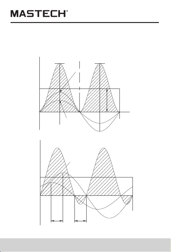
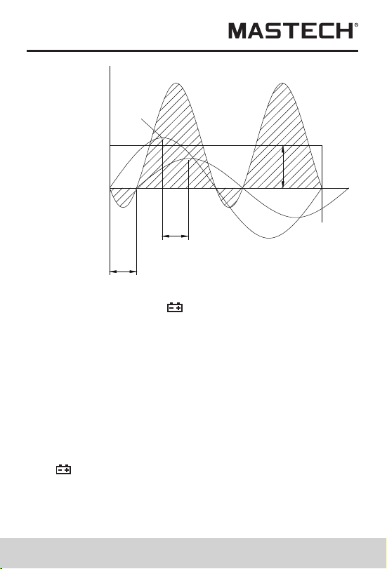
Power curve diagram
(Active power=apparent power × PF)
using wrist belt can prevent unintended dropping of the
meter.
+V
+I
+P
P
+i
MAX
I
MAX
v
+v
-i
-V
X
-E
-I
-P
360
O
180
O
0
-
0
-
2000W 2000W
+E
+I
+P
360
O
-E
-I
-P
ACTIVE POWER
1000W
PEAK VALUE
E =141V
PEAK VALUE OF POWER
POWER
=14A
PEAK VALUE
PF=1
180
O
90
O
MAX
I
MAX
PF=kW/kVA
+V
+I
+P
P
0
-
-E
-I
-P
0
-
O
45
O
O
45
O
45
O
O
90
O
180
O
225
O
270
O
360
O
kW=I R
2
ACTIVE POWER
500W
MAX
I
MAX
v
Battery-low Indication
If battery voltage is low, “ ” symbol will be displayed on
the upper right corner of LCD. Then, it is needed to
replace new batteries.
Battery Replacement
Warning
1.Before opening the back lid to replace batteries, please
make sure the meter is turned off and no test probe is
connected to any test wire so as to avoid electrical
shock; before using the meter, please make sure the
back lid is tightly closed. Only batteries of identical
model or electrical specification can be used.
2.If “ ”symbol is shown on LCD, it signifies that battery
voltage with load is lower than the minimum voltage for
ensuring measurement error limits, and the meter will
prompt you to change new batteries. Please follow the
steps below to replace batteries:
25 26
Power curve diagram
(Active power=apparent power × PF)
using wrist belt can prevent unintended dropping of the
meter.
+V
+I
+P
P
+i
MAX
I
MAX
v
+v
-i
-V
X
-E
-I
-P
360
O
180
O
0
-
0
-
2000W 2000W
+E
+I
+P
360
O
-E
-I
-P
ACTIVE POWER
1000W
PEAK VALUE
E =141V
PEAK VALUE OF POWER
POWER
=14A
PEAK VALUE
PF=1
180
O
90
O
MAX
I
MAX
PF=kW/kVA
+V
+I
+P
P
0
-
-E
-I
-P
0
-
O
45
O
O
45
O
45
O
O
90
O
180
O
225
O
270
O
360
O
kW=I R
2
ACTIVE POWER
500W
MAX
I
MAX
v
Battery-low Indication
If battery voltage is low, “ ” symbol will be displayed on
the upper right corner of LCD. Then, it is needed to
replace new batteries.
Battery Replacement
Warning
1.Before opening the back lid to replace batteries, please
make sure the meter is turned off and no test probe is
connected to any test wire so as to avoid electrical
shock; before using the meter, please make sure the
back lid is tightly closed. Only batteries of identical
model or electrical specification can be used.
2.If “ ”symbol is shown on LCD, it signifies that battery
voltage with load is lower than the minimum voltage for
ensuring measurement error limits, and the meter will
prompt you to change new batteries. Please follow the
steps below to replace batteries:
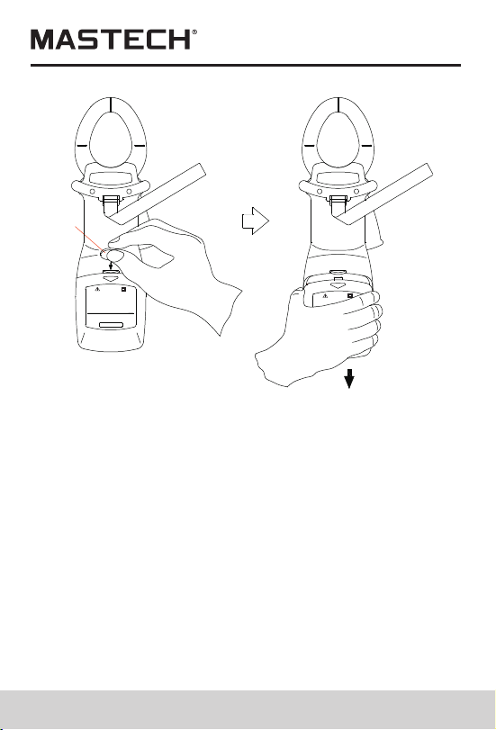
27 28
3.Disconnect test probes from test circuit, and rotate
function-switching knob to “OFF”, and then take off
test probes from the input sockets.
Open battery cover, and pay attention to the self-
locking structure of the cover; you can open the
cover as per Figure 23: insert a coin to the slot on the
cover, and press down the coin to open the lock
buckle, and then slide off the cover downward.
Please do not use tapered tool to pry open the cover,
otherwise meter housing will be damaged.
5.Take out old batteries, and replace them with 4 new
1.5 V batteries. New batteries shall not be used
together with old ones.
6.Properly close the battery cover.
4.
PLEASE READ MANUAL FOR SAFETY.TO AVOID
ELECTRICAL SHOCK NEVER CONNECT THE TEST
LEADS TO THE INPUT JACKS WHICH ARE NOT
FORRELATED MEASURING AND REMOVE ALL
INPUTS BEFORE OPENING CASE.
BATTERIES : 4 X 1.5 V SIZE AA
WARNING
OPEN
600V CAT.III
IEC1010-1
POLLUTION DEGREE 2
IEC1010-2-032
PLEASE READ MANUAL FOR
ELECTRICAL SHOT
WARNING
OPEN
Coin
General specification
Complies with IEC/EN 61010-1 1000V CAT II ,600 V
CAT III
1.Max. common-mode voltage: 600V AC RMS
2.Mode of display: LCD display; Max. reading: 6000
3.Range selection: Fully automatic range selection
4.Frequency detection: automatic (when harmonic is
serious, it is better to use manual settings for testing
frequency so as to assure the reading stability)
5.Over-range display: “OL”
6.Data holding: “HOLD” is shown on LCD
7.Power supply: 4 batteries of 1.5 V, AA
8.Power consumption: 250 mW
9.Storage temperature: - 20 °C ~ 70 °C
10.Operating temperature: 0 °C ~ 40 °C
11.Temperature Coefficient:0.05×(specified accuracy)
per°C
12.Electromagnetic Compatibility: In an RF field of 3V/M,
accuracy=specified accuracy , Otherwise accuracy is
unspecifieced.
13.Operating Altitude: 2000m CAT lll 600V;3000m
CAT ll 600V
14.Store Altitude: 12000m
15.Dimensions: 300mm×103mm×51mm
Weight: about 500 g (with battery) 16.
Technical specification
Accuracy: ±(% read + graduation #) ambient
temperature: 18°C ~ 28°C, Humidity 80%, frequency for
voltage, current: 45 Hz ~ 65 Hz
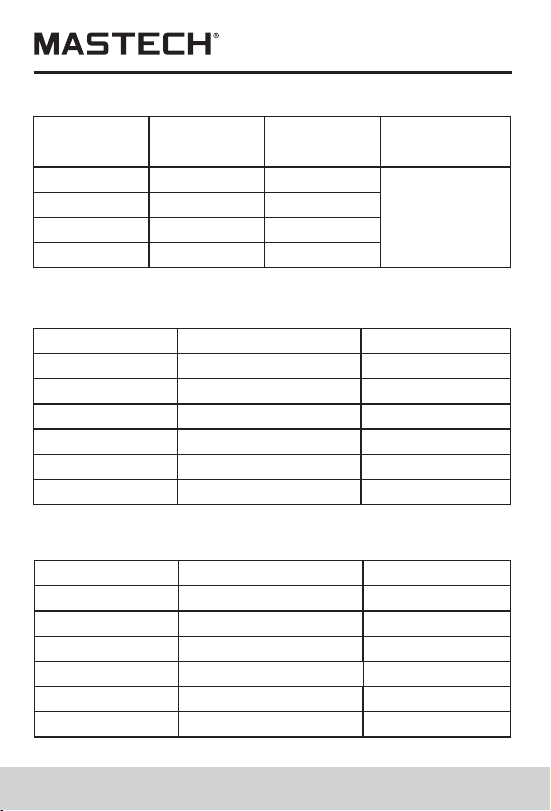
29 30
Range Accuracy
Resolution
Input
impedance
80V
180V
400V
600V
± (1.0%+5)
0.1V
0.1V
1V
1V
1 MΩ //
10 pF
± (1.0%+5)
± (1.0%+5)
± (1.0%+5)
AC voltage RMS
Max. allowed overload voltage: 750 V (RMS)
Range
20A
40A
100A
200A
AC Current
Max. allowed overload current: 1200 A
Accuracy
± (2%+5)
± (2%+5)
± (2%+5)
± (2%+5)
RMS
± (2%+5)
± (2%+5)
450A
1000A
Resolution
0.01A
0.01A
0.1A
0.1A
1A
1A
Range
30kW
60kW
120kW
150kW
Single-phase active power (W)
Min. test current: 2A; Min. test voltage: 50V
Accuracy
± (3%+5)
± (3%+5)
± (3%+5)
± (3%+5)
± (3%+5)
± (3%+5)
300kW
600kW
Resolution
0.01kW
0.01kW
0.1kW
0.1kW
0.1kW
0.1kW
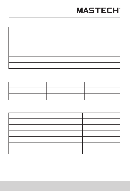
Range
3kVA
12kVA
30kVA
120kVA
Three-phase active power (W)
Min. test current: 2A; Min. test voltage: 50V
Accuracy
± (3%+5)
± (3%+5)
± (3%+5)
± (3%+5)
± (3%+5)
± (3%+5)
150kVA
600kVA
Resolution
0.001kVA
0.01kW
0.01kVA
0.1kVA
0.1kVA
0.1kVA
Range Accuracy
Resolution
0.3~1 Capacitive
0.3~1 Inductive
± (0.02+2)
0.001
0.001
± (0.02+2)
Power factor
Min. test current: 2A; Min. test voltage: 50V
Range
3kVAr
12kVAr
30kVAr
120kVAr
Passive power
Min. input current: 2A; Min. input voltage: 50V
Accuracy
± (3%+5)
± (3%+5)
± (3%+5)
± (3%+5)
± (3%+5)
± (3%+5)
150kVAr
600kVAr
Resolution
0.001kVAr
0.01kWr
0.01kVAr
0.1kVAr
0.1kVAr
0.1kVAr
Passive power Var is calculated according to the
measured V, A, and kW value。
29 30
Range Accuracy
Resolution
Input
impedance
80V
180V
400V
600V
± (1.0%+5)
0.1V
0.1V
1V
1V
1 MΩ //
10 pF
± (1.0%+5)
± (1.0%+5)
± (1.0%+5)
AC voltage RMS
Max. allowed overload voltage: 750 V (RMS)
Range
20A
40A
100A
200A
AC Current
Max. allowed overload current: 1200 A
Accuracy
± (2%+5)
± (2%+5)
± (2%+5)
± (2%+5)
RMS
± (2%+5)
± (2%+5)
450A
1000A
Resolution
0.01A
0.01A
0.1A
0.1A
1A
1A
Range
30kW
60kW
120kW
150kW
Single-phase active power (W)
Min. test current: 2A; Min. test voltage: 50V
Accuracy
± (3%+5)
± (3%+5)
± (3%+5)
± (3%+5)
± (3%+5)
± (3%+5)
300kW
600kW
Resolution
0.01kW
0.01kW
0.1kW
0.1kW
0.1kW
0.1kW
Range
3kVA
12kVA
30kVA
120kVA
Three-phase active power (W)
Min. test current: 2A; Min. test voltage: 50V
Accuracy
± (3%+5)
± (3%+5)
± (3%+5)
± (3%+5)
± (3%+5)
± (3%+5)
150kVA
600kVA
Resolution
0.001kVA
0.01kW
0.01kVA
0.1kVA
0.1kVA
0.1kVA
Range Accuracy
Resolution
0.3~1 Capacitive
0.3~1 Inductive
± (0.02+2)
0.001
0.001
± (0.02+2)
Power factor
Min. test current: 2A; Min. test voltage: 50V
Range
3kVAr
12kVAr
30kVAr
120kVAr
Passive power
Min. input current: 2A; Min. input voltage: 50V
Accuracy
± (3%+5)
± (3%+5)
± (3%+5)
± (3%+5)
± (3%+5)
± (3%+5)
150kVAr
600kVAr
Resolution
0.001kVAr
0.01kWr
0.01kVAr
0.1kVAr
0.1kVAr
0.1kVAr
Passive power Var is calculated according to the
measured V, A, and kW value。
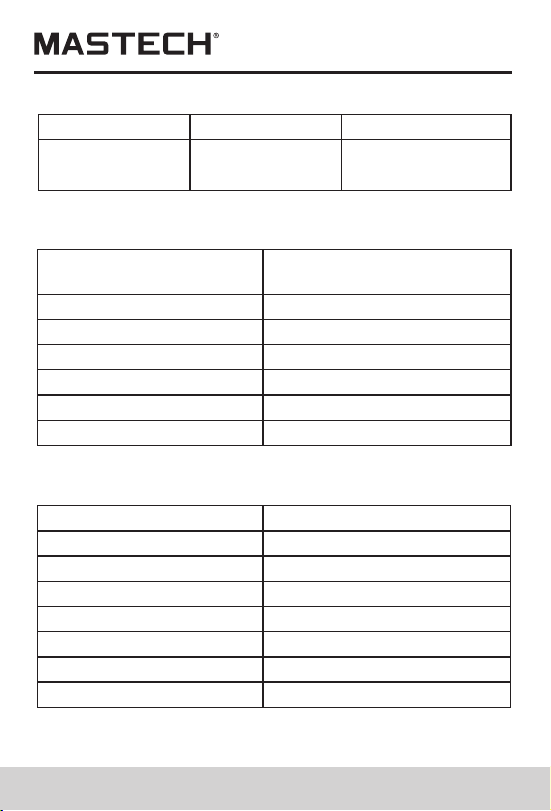
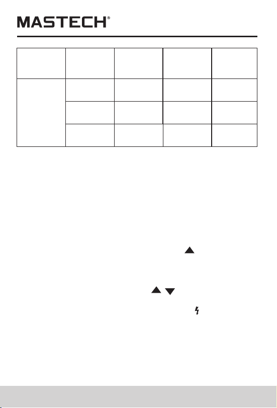
29 30
Harmonic number
Precision of harmonic
voltage
1
2-6
7-8
9-10
± (3.0%+10)
± (3.5%+10)
± (4.5%+10)
± (5.0%+10)
Harmonic test
Min. test voltage 50V;Min test current 2A
± (7%+10)
± (10%+10)
11-15
16-20
Range
Accuracy
Resolution
30Hz~1000Hz
0.5% + 1
graduation
0.1Hz
Frequency
Min. test voltage: 50 V
Item
Quantity
Instruction Manual
1.5VAA Battery
Test probe
Test clip
×1
×4
×1
×3
Accessories
Quality Assurance
×1
×1
Interface cable
PC Software CD
×1
Package box
Thank you for using the product of our company; this
product has a warranty period of one year starting from
purchasing date.
This product has passed the strict quality test of our
company. Our company will exert our efforts to do after-
sales service for you in accordance with the
Warranty instructions.
In case there is any problem occurred during warranty
period, which is resulted from product quality problem,
please fill in the warranty card and mail it in together with
the product, and the service department of our company
will repair it or replace it free of charge, while the user
himself/herself shall not take the meter apart.
When warranty period is over, the repairing will be charged
Free service does not apply to the
following cases:
Problems and damages due to improper use or use
under environment which is not stipulated for this
product, including overloading.
Problems and damages due to unauthorized dismantling
or refitting and misuse.
Problems and damages due to user reasons.
Problems and damages due to natural disasters.
00-05-xxxx
Replace test leads if leads become damaged or worn.
Use meet EN 61010-031 standard, rated CAT III 600V, or
better test leads.
WARNING
Replacing The Batteries
WARNING
To avoid electric shock, make sure that the test
leads have been clearly move away from the
circuit under measurement before opening the
battery cover of the meter.
5.1.1 If the sign “ ” appears, it means that the
batteries should be replaced.
5.1.2 Loosen the fixing screw of the battery cover and
remove it.
5.1.3 Replace the exhausted batteries with new ones.
5.1.4 Put the battery cover back and fix it again to its
origin form.
Note:
Do not reverse the polarity of the batteries.
WARNING
Do not mix old and new batteries. Do not mix
alkaline, standard (carbon-zinc), or rechargeable
(ni-cad, ni-mh, etc) batteries.
Replacing Test Leads