Owner's Manual
IC..FTSMnWl
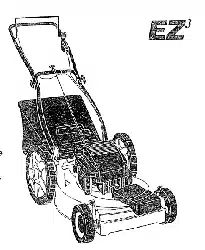
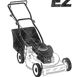
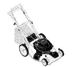
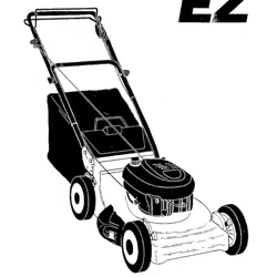
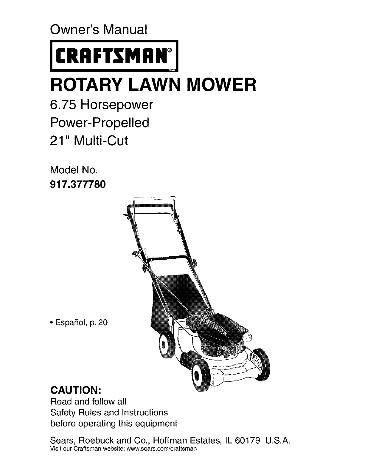
ROTARY LAWN MOWER
6.75 Horsepower
Power-Propelled
21" Multi-Cut
Model No.
917.377780
• EspaSol, p. 20
CAUTION:
Read and follow all
Safety Rules and Instructions
before operating this equipment
Sears, Roebuck and Co., Hoffman Estates, IL 60179 U.S.A.
Visit our Craftsman website: www.sears.com/craftsman
Warranty ................................................... 2
Safety Rules .......................................... 2-4
Product Specifications .............................. 4
Assembly / Pre-Operation ........................ 6
Operation ............................................ 7-11
Maintenance Schedule ........................... 12
Maintenance ...................................... 12-15
Service and Adjustments ................... 15-16
Storage .............................................. 17-18
Troubleshooting ................................. 18-19
Repair Parts ....................................... 38-45
Sears Service .......................... Back Cover
LIMITED TWO YEAR WARRANTY ON CRAFTSMAN POWER MOWER
For two years from date of purchase, when this Craftsman Lawn Mower is maintained,
lubricated, and tuned up according to the operating and maintenance instructions in the
owner's manual, Sears will repair free of charge any defect in material or workmanship.
If this Craftsman Lawn Mower is used for commercial or rental purposes, this warranty
applies for only 90 days from the date of purchase.
This Warranty does not cover:
• Expendable items which become worn during normal use, such as rotary mower
blades, blade adapters, belts, air cleaners and spark plug.
• Repairs necessary because of operator abuse or negligence, including bent crank-
shafts and the failure to maintain the equipment according to the instructions con-
tained in the owner's manual.
Warranty service is available by returning the Craftsman power mower to the nearest
Sears Parts & Repair Center in the United States. This warranty applies only while this
product is used in the United States.
This Warranty gives you specific legal rights, and you may also have other rights which
vary from state to state.
Sears, Roebuck And Co., D/817 WA, Hoffman Estates, Illinois 60179
IMPORTANT: This cutting machine is capable of amputating hands and feet and throw-
ing objects. Failure to observe the following safety instructions could result in serious
injury or death.
_,Look for this symbol to point out
important safety precautions. It means
CAUTION!H BECOME ALERT!H
YOUR SAFETY IS INVOLVED.
&WARNING: In order to prevent ac-
cidental starting when setting up, trans-
porting, adjusting or making repairs,
always disconnect spark plug wire and
place wire where it cannot come in con-
tact with plug.
_,WARNING: Battery posts, terminals and
related accessories contain lead and lead
compounds, chemicals known to the State
of California to cause cancer and birth
defects or other reproductive harm. Wash
hands after handling.
_,WARNING: Engine exhaust, some of its
constituents, and certain vehicle compo-
nents contain or emit chemicals known
to the State of California to cause cancer
and birth defects or other reproductive
harm.
2
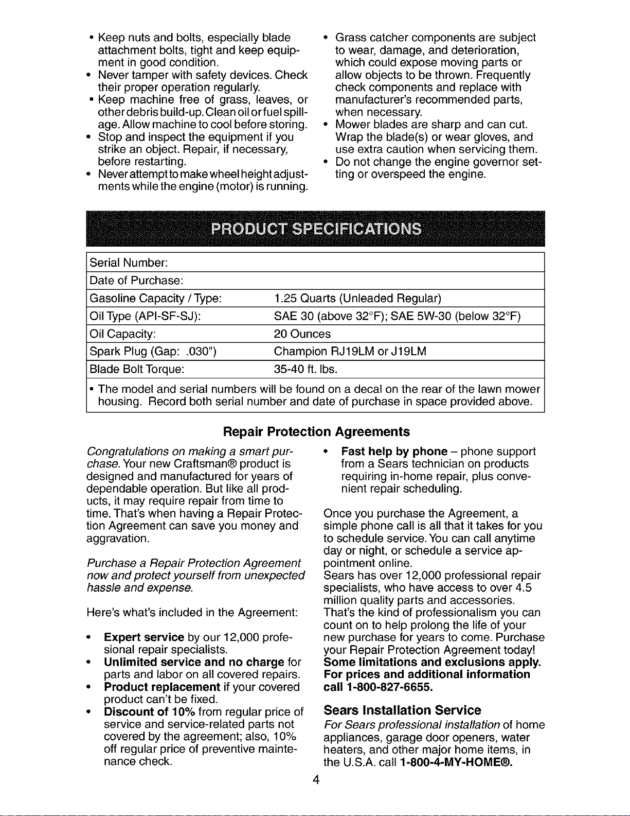
_, CAUTION: Muffler and other engine
parts become extremely hot during
operation and remain hot after engine has
stopped. To avoid severe burns on contact,
stay away from these areas.

I. GENERAL OPERATION
• Read, understand, and follow all
instructions on the machine and in the
manual(s) before starting. Be thoroughly
familiar with the controls and the proper
use of the machine before starting.
• Do not put hands or feet near or under
rotating parts. Keep clear of the dis-
charge opening at all times.
• Only allow responsible individuals, who
are familiar with the instructions, to
operate the machine.
• Clear the area of objects such as rocks,
toys, wire, bones, sticks, etc., which
could be picked up and thrown by the
blade.
• Be sure the area is clear of other people
before mowing. Stop machine if anyone
enters the area.
• Do not operate the mower when bare-
foot or wearing open sandals. Always
wear substantial foot wear.
• Do not pull mower backwards unless
absolutely necessary. Always look down
and behind before and while moving
backwards.
• Do not operate the mower without
proper guards, plates, grass catcher or
other safety protective devices in place.
• See manufacturer's instructions for
proper operation and installation of
accessories. Only use accessories ap-
proved by the manufacturer.
• Stop the blade(s) when crossing gravel
drives, walks, or roads.
• Stop the engine (motor) whenever you
leave the equipment, before cleaning
the mower or unclogging the chute.
• Shut the engine (motor) off and wait
until the blade comes to complete stop
before removing grass catcher.
• Mow only in daylight or good artificial
light.
• Do not operate the machine while under
the influence of alcohol or drugs.
• Never operate machine in wet grass.
Always be sure of your footing: keep a
firm hold on the handle and walk; never
run.
• Disengage the self-propelled mech-
anism or drive clutch on mowers so
equipped before starting the engine
(motor).
• If the equipment should start to vibrate
abnormally, stop the engine (motor) and
check immediately for the cause. Vibra-
tion is generally a warning of trouble.
• Always wear safety goggles or safety
glasses with side shields when oper-
ating mower.
II. SLOPE OPERATION
Slopes are a major factor related to slip
and fall accidents which can result in
severe injury. All slopes require extra cau-
tion. If you feel uneasy on a slope, do not
mow it.
DO:
• Mow across the face of slopes: never
up and down. Exercise extreme caution
when changing direction on slopes.
• Remove obstacles such as rocks, tree
limbs, etc.
• Watch for holes, ruts, or bumps. Tall
grass can hide obstacles.
DO NOT:
• Do not trim near drop-offs, ditches or
embankments. The operator could lose
footing or balance.
• Do not trim excessively steep slopes.
• Do not mow on wet grass. Reduced foot-
ing could cause slipping.
III. CHILDREN
Tragic accidents can occur ifthe operator
is not alert to the presence of children.
Children are often attracted to the machine
and the mowing activity. Never assume
that children will remain where you last
saw them.
• Keep children out of the trimming area
and under the watchful care of another
responsible adult.
• Be alert and turn machine off if children
enter the area.
• Before and while walking backwards,
look behind and down for small children.
• Never allow children to operate the ma-
chine.
• Use extra care when approaching blind
corners, shrubs, trees, or other objects
that may obscure vision.
IV. SERVICE
• Use extra care in handling gasoline and
other fuels. They are flammable and
vapors are explosive.
- Use only an approved container.
- Never remove gas cap or add fuel
with the engine running.
Allow engine to cool before refueling.
Do not smoke.
- Never refuel the machine indoors.
- Never store the machine or fuel
container inside where there is an
open flame, such as a water heater.
• Never run a machine inside a closed area.
• Never make adjustments or repairs with
the engine (motor) running. Disconnect the
spark plug wire, and keep the wire away
3 from the plug toprevent accidental starting.
• Keepnutsandbolts,especiallyblade
attachmentbolts,tightand keepequip-
mentingoodcondition.
• Nevertamperwith safetydevices.Check
theirproperoperationregularly.
• Keep machine free of grass, leaves,or
otherdebrisbuild-up.Cleanoilorfuelspill-
age.Allowmachinetocoolbeforestoring.
• Stopandinspecttheequipmentifyou
strikean object.Repair,if necessary,
beforerestarting.
• Neverattempttomakewheelheightadjust-
mentswhiletheengine(motor)isrunning.
• Grasscatchercomponentsaresubject
to wear,damage,anddeterioration,
whichcouldexposemovingpartsor
allowobjectsto bethrown.Frequently
checkcomponentsand replacewith
manufacturer'srecommendedparts,
whennecessary.
• Mowerbladesare sharpandcan cut.
Wraptheblade(s)orweargloves,and
useextracautionwhenservicingthem.
• Donotchangethe enginegovernorset-
ting oroverspeedtheengine.
SerialNumber:
Dateof Purchase:
GasolineCapacity/Type: 1.25 Quarts (Unleaded Regular)
Oil Type (API-SF-SJ): SAE 30 (above 32°F); SAE 5W-30 (below 32°F)
Oil Capacity: 20 Ounces
Spark Plug (Gap: .030") Champion RJ19LM or J19LM
Blade Bolt Torque: 35-40 ft. Ibs.
• The model and serial numbers will be found on a decal on the rear of the lawn mower
housing. Record both serial number and date of purchase in space provided above.
Repair Protection Agreements
Congratulations on making a smart pur-
chase. Your new Craftsman® product is
designed and manufactured for years of
dependable operation. But like all prod-
ucts, it may require repair from time to
time. That's when having a Repair Protec-
tion Agreement can save you money and
aggravation.
Purchase a Repair Protection Agreement
now and protect yourself from unexpected
hassle and expense.
Here's what's included in the Agreement:
• Expert service by our 12,000 profe-
sional repair specialists.
• Unlimited service and no charge for
parts and labor on all covered repairs.
• Product replacement if your covered
product can't be fixed.
• Discount of 10% from regular price of
service and service-related parts not
covered by the agreement; also, 10%
off regular price of preventive mainte-
nance check.
Fast help by phone - phone support
from a Sears technician on products
requiring in-home repair, plus conve-
nient repair scheduling.
Once you purchase the Agreement, a
simple phone call is all that it takes for you
to schedule service. You can call anytime
day or night, or schedule a service ap-
pointment online.
Sears has over 12,000 professional repair
specialists, who have access to over 4.5
million quality parts and accessories.
That's the kind of professionalism you can
count on to help prolong the life of your
new purchase for years to come. Purchase
your Repair Protection Agreement today!
Some limitations and exclusions apply.
For prices and additional information
call 1-800-827-6655.
Sears Installation Service
For Sears professional installation of home
appliances, garage door openers, water
heaters, and other major home items, in
the U.S.A. call 1-800-4-MY-HOME®.
4
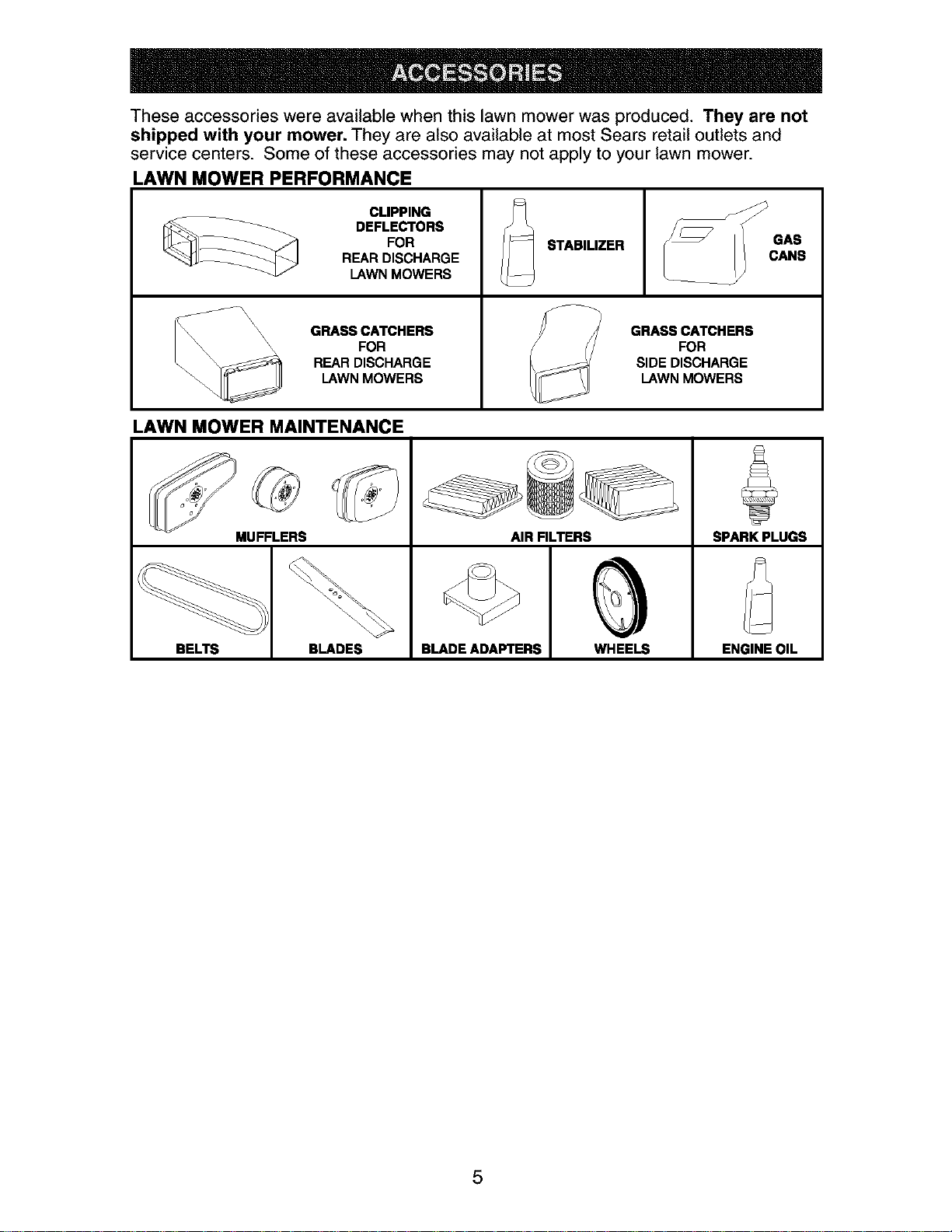
These accessories were available when this lawn mower was produced. They are not
shipped with your mower. They are also available at most Sears retail outlets and
service centers. Some of these accessories may not apply to your lawn mower.
LAWN MOWER PERFORMANCE
CLIPPING
DEFLECTORS
FOR
REAR DISCHARGE
LAWN MOWERS
\\ GRASS CATCHERS
_\_ \\\ FOR
REAR DISCHARGE
LAWN MOWERS
STABILIZER
GRASS CATCHERS
FOR
SIDE DISCHARGE
LAWN MOWERS
GAS
CANS
LAWN MOWER MAINTENANCE
MUFFLERS AIR FILTERS SPARK PLUGS
BELTS BLADES BLADE ADAPTERS WHEELS ENGINE OIL
5
Read these instructions and this manual in
its entirety before you attempt to assemble
or operate your new lawn mower.
IMPORTANT: This lawn mower is shipped
WITHOUT OIL OR GASOLINE inthe engine.
Your new lawn mower has been as-
sembled at the factory with the excep-
tion of those parts left unassembled for
shipping purposes. To ensure safe and
proper operation of your lawn mower, all
parts and hardware you assemble must be
tightened securely. Use the correct tools
as necessary to ensure proper tightness.
All parts such as nuts, washers, bolts, etc.,
necessary to complete the assembly have
been placed in the parts bag.
TO REMOVE LAWN MOWER FROM
CARTON
1. Remove loose parts included with
mower.
2. Cut down two end corners of carton
and lay end panel down flat.
3. Remove all packing materials except
padding between upper and lower
handle and padding holding operator
presence control bar to upper handle.
4. Roll lawn mower out of carton and
check carton thoroughly for additional
loose parts.
HOWTO SET UPYOUR LAWN
MOWER
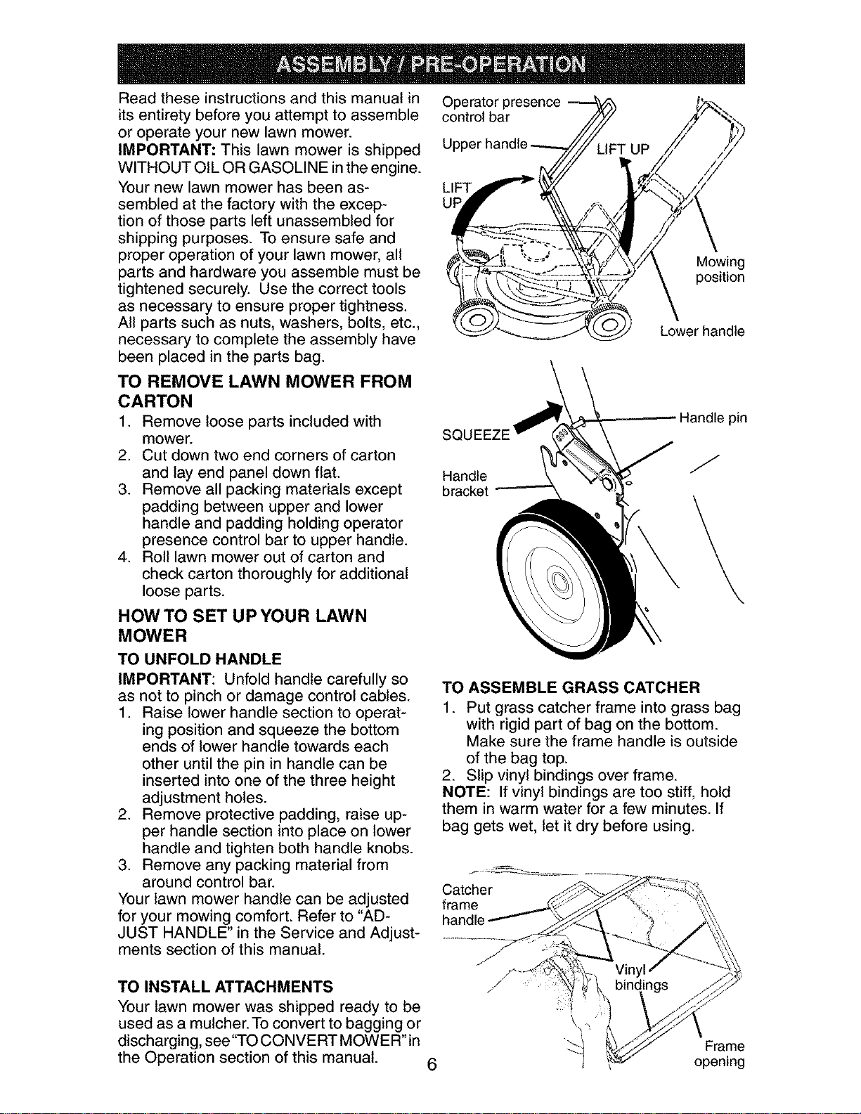
TO UNFOLD HANDLE
IMPORTANT: Unfold handle carefully so
as not to pinch or damage control cables.
1. Raise lower handle section to operat-
ing position and squeeze the bottom
ends of lower handle towards each
other until the pin in handle can be
inserted into one of the three height
adjustment holes.
2. Remove protective padding, raise up-
per handle section into place on lower
handle and tighten both handle knobs.
3. Remove any packing material from
around control bar.
Your lawn mower handle can be adjusted
for your mowing comfort. Refer to "AD-
JUST HANDLE" in the Service and Adjust-
ments section of this manual.
Operator presence
control bar
LIFT
UF
Mowing
position
Lower handle
SQL
Handle
bracket
Handle pin
J
TO ASSEMBLE GRASS CATCHER
1. Put grass catcher frame into grass bag
with rigid part of bag on the bottom.
Make sure the frame handle is outside
of the bag top.
2. Slip vinyl bindings over frame.
NOTE: If vinyl bindings are too stiff, hold
them in warm water for a few minutes. If
bag gets wet, let it dry before using.
Catcher
frame
handle
TO INSTALL ATTACHMENTS
Your lawn mower was shipped ready to be
used as a mulcher. To convert to bagging or
discharging, see"TO CONVERT MOWER"in
the Operation section of this manual.
6
Frame
opening
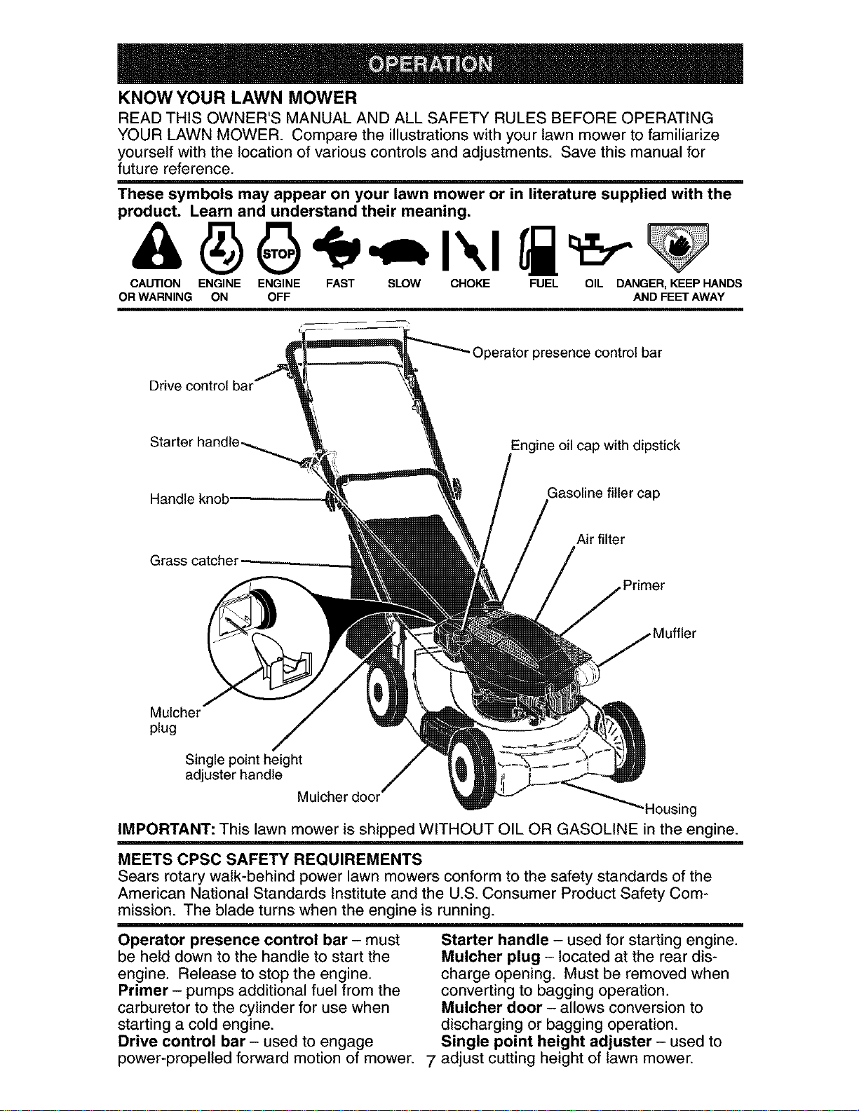
KNOW YOUR LAWN MOWER
READ THIS OWNER'S MANUAL AND ALL SAFETY RULES BEFORE OPERATING
YOUR LAWN MOWER. Compare the illustrations with your lawn mower to familiarize
yourself with the location of various controls and adjustments. Save this manual for
future reference.
These symbols may appear on your lawn mower or in literature supplied with the
product. Learn and understand their meaning.
CAUTION ENGINE ENGINE FAST SLOW CHOKE FUEL OIL DANGER,KEEP HANDS
OR WARNING ON OFF AND FEET AWAY
- Operator presence control bar
Drive control bar
Engine oil cap with dipstick
Handle Gasoline filler cap
Grass catcher
Air filter
Mulcher
plug
Single point height
adjuster handle
Mulcher door
,Housing
IMPORTANT: This lawn mower is shipped WITHOUT OIL OR GASOLINE in the engine.
m
MEETS CPSC SAFETY REQUIREMENTS
Sears rotary walk-behind power lawn mowers conform to the safety standards of the
American National Standards Institute and the U.S. Consumer Product Safety Com-
mission. The blade turns when the engine is running.
Operator presence control bar - must
be held down to the handle to start the
engine. Release to stop the engine.
Primer - pumps additional fuel from the
carburetor to the cylinder for use when
starting a cold engine.
Drive control bar - used to engage
Starter handle - used for starting engine.
Mulcher plug - located at the rear dis-
charge opening. Must be removed when
converting to bagging operation.
Mulcher door - allows conversion to
discharging or bagging operation.
Single point height adjuster - used to
power-propelled forward motion of mower. 7 adjust cutting height of lawn mower.
Theoperationof any lawn
mowercan resultin foreign
objectsthrownintothe
eyes,whichcan resultin
severeeye damage.Always
wearsafetyglassesor eyeshieldswhile
operatingyourlawnmowerorperforming
any adjustmentsor repairs.We recom-
mendastandardsafetyglassesor wide
visionsafetymaskwornoverspectacles.
HOW TO USE YOUR LAWN MOWER
ENGINE SPEED
The engine speed was set at the factory
for optimum performance. Speed is not
adjustable.
ENGINE ZONE CONTROL
_CAUTION: Federal regulations require
an engine control to be installed on this
lawn mower in order to minimize the
risk of blade contact injury. Do not under
any circumstances attempt to defeat the
function of the operator control. The blade
turns when the engine is running.
• Your lawn mower is equipped with an
operator presence control bar which
requires the operator to be positioned
behind the lawn mower handle to start
and operate the lawn mower.
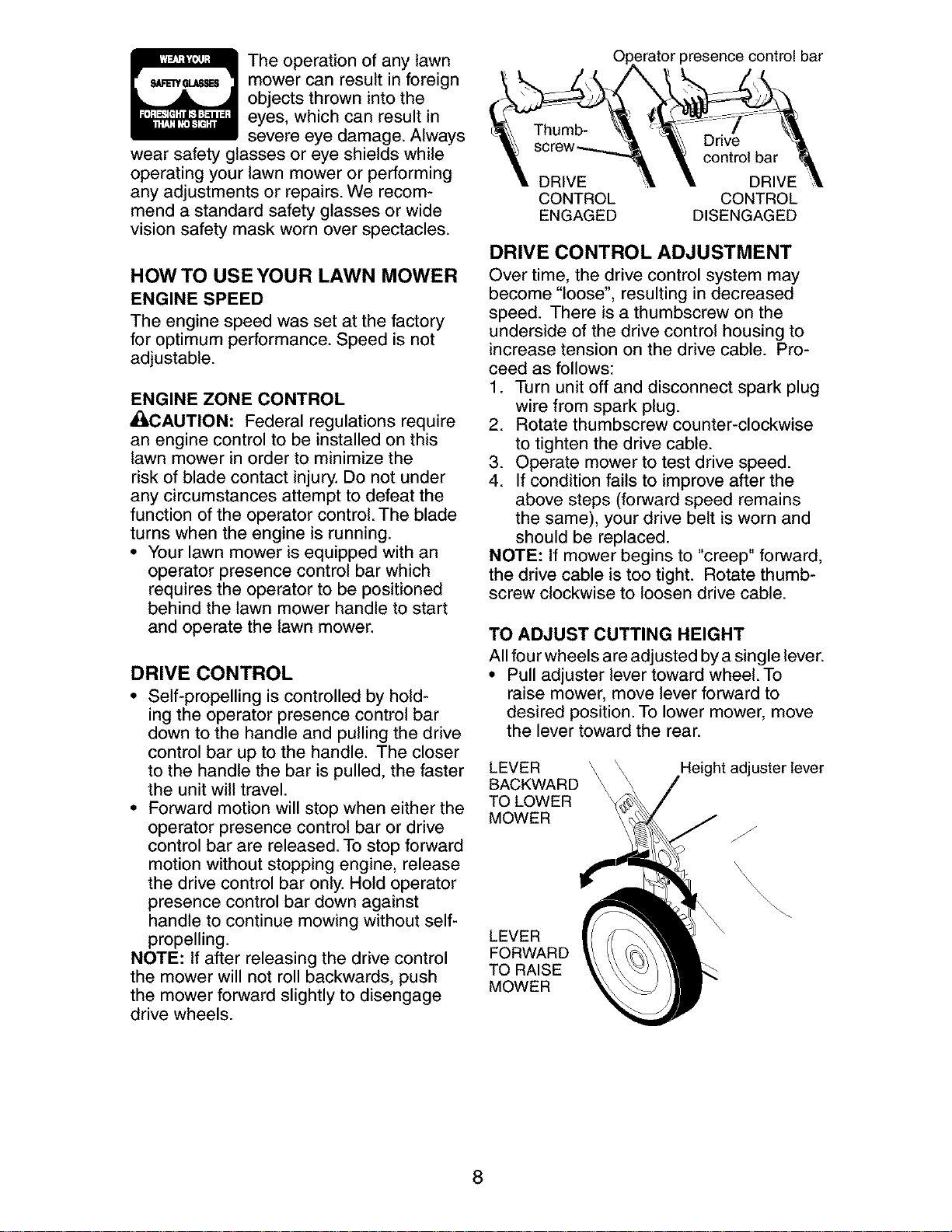
DRIVE CONTROL
• Self-propelling is controlled by hold-
ing the operator presence control bar
down to the handle and pulling the drive
control bar up to the handle. The closer
to the handle the bar is pulled, the faster
the unit will travel.
• Forward motion will stop when either the
operator presence control bar or drive
control bar are released. To stop forward
motion without stopping engine, release
the drive control bar only. Hold operator
presence control bar down against
handle to continue mowing without self-
propelling.
NOTE: If after releasing the drive control
the mower will not roll backwards, push
the mower forward slightly to disengage
drive wheels.
_rator presence control bar
contmlbar
DRIVE DRIVE
CONTROL CONTROL
ENGAGED DISENGAGED
DRIVE CONTROL ADJUSTMENT
Over time, the drive control system may
become "loose", resulting in decreased
speed. There is a thumbscrew on the
underside of the drive control housing to
increase tension on the drive cable. Pro-
ceed as follows:
1. Turn unit off and disconnect spark plug
wire from spark plug.
2. Rotate thumbscrew counter-clockwise
to tighten the drive cable.
3. Operate mower to test drive speed.
4. If condition fails to improve after the
above steps (forward speed remains
the same), your drive belt is worn and
should be replaced.
NOTE: If mower begins to "creep" forward,
the drive cable is too tight. Rotate thumb-
screw clockwise to loosen drive cable.
TO ADJUST CUTTING HEIGHT
All four wheels are adjusted by a single lever.
• Pull adjuster lever toward wheel. To
raise mower, move lever forward to
desired position. To lower mower, move
the lever toward the rear.
LEVER
BACKWARD
TO LOWER
MOWER
Height adjuster lever
LEVER
FORWARD
TO RAISE
MOWER
8
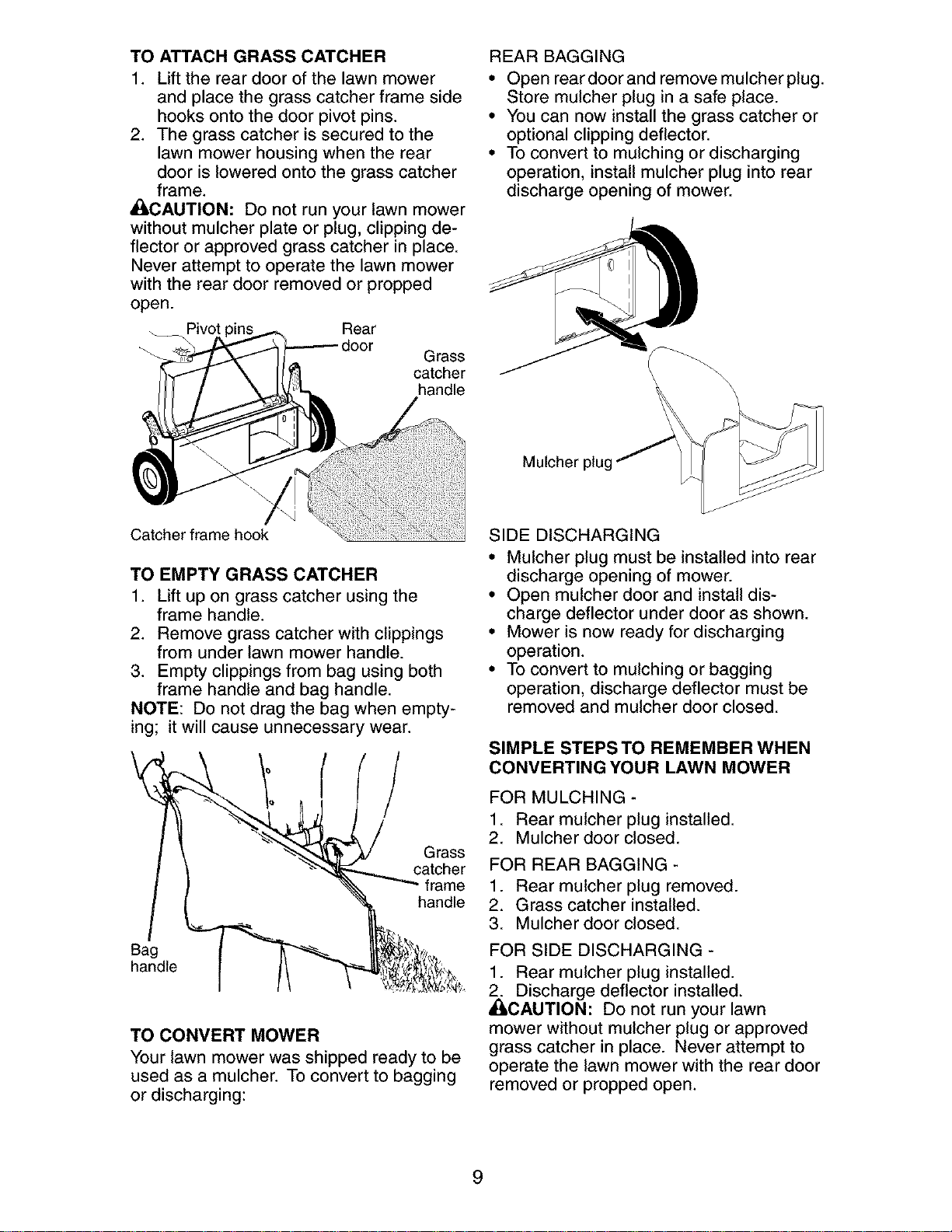
TO ATTACH GRASS CATCHER
1. Lift the rear door of the lawn mower
and place the grass catcher frame side
hooks onto the door pivot pins.
2. The grass catcher is secured to the
lawn mower housing when the rear
door is lowered onto the grass catcher
frame.
_CAUTION: Do not run your lawn mower
without mulcher plate or plug, clipping de-
flector or approved grass catcher in place.
Never attempt to operate the lawn mower
with the rear door removed or propped
open.
_Pivot " Rear
Grass
catcher
handle
Catcher frame hook
TO EMPTY GRASS CATCHER
1. Lift up on grass catcher using the
frame handle.
2. Remove grass catcher with clippings
from under lawn mower handle.
3. Empty clippings from bag using both
frame handle and bag handle.
NOTE: Do not drag the bag when empty-
ing; it will cause unnecessary wear.
Grass
catcher
frame
handle
Bag
handle
TO CONVERT MOWER
Your lawn mower was shipped ready to be
used as a mulcher. To convert to bagging
or discharging:
REAR BAGGING
• Open rear door and remove mulcher plug.
Store mulcher plug in a safe place.
• You can now install the grass catcher or
optional clipping deflector.
• To convert to mulching or discharging
operation, install mulcher plug into rear
discharge opening of mower.
\
Mulcher
SIDE DISCHARGING
• Mulcher plug must be installed into rear
discharge opening of mower.
• Open mulcher door and install dis-
charge deflector under door as shown.
• Mower is now ready for discharging
operation.
• To convert to mulching or bagging
operation, discharge deflector must be
removed and mulcher door closed.
SIMPLE STEPS TO REMEMBER WHEN
CONVERTING YOUR LAWN MOWER
FOR MULCHING -
1. Rear mulcher plug installed.
2. Mulcher door closed.
FOR REAR BAGGING -
1. Rear mulcher plug removed.
2. Grass catcher installed.
3. Mulcher door closed.
FOR SIDE DISCHARGING -
1. Rear mulcher plug installed.
_ Discharge deflector installed.
CAUTION: Do not run your lawn
mower without mulcher plug or approved
grass catcher in place. Never attempt to
operate the lawn mower with the rear door
removed or propped open.
9
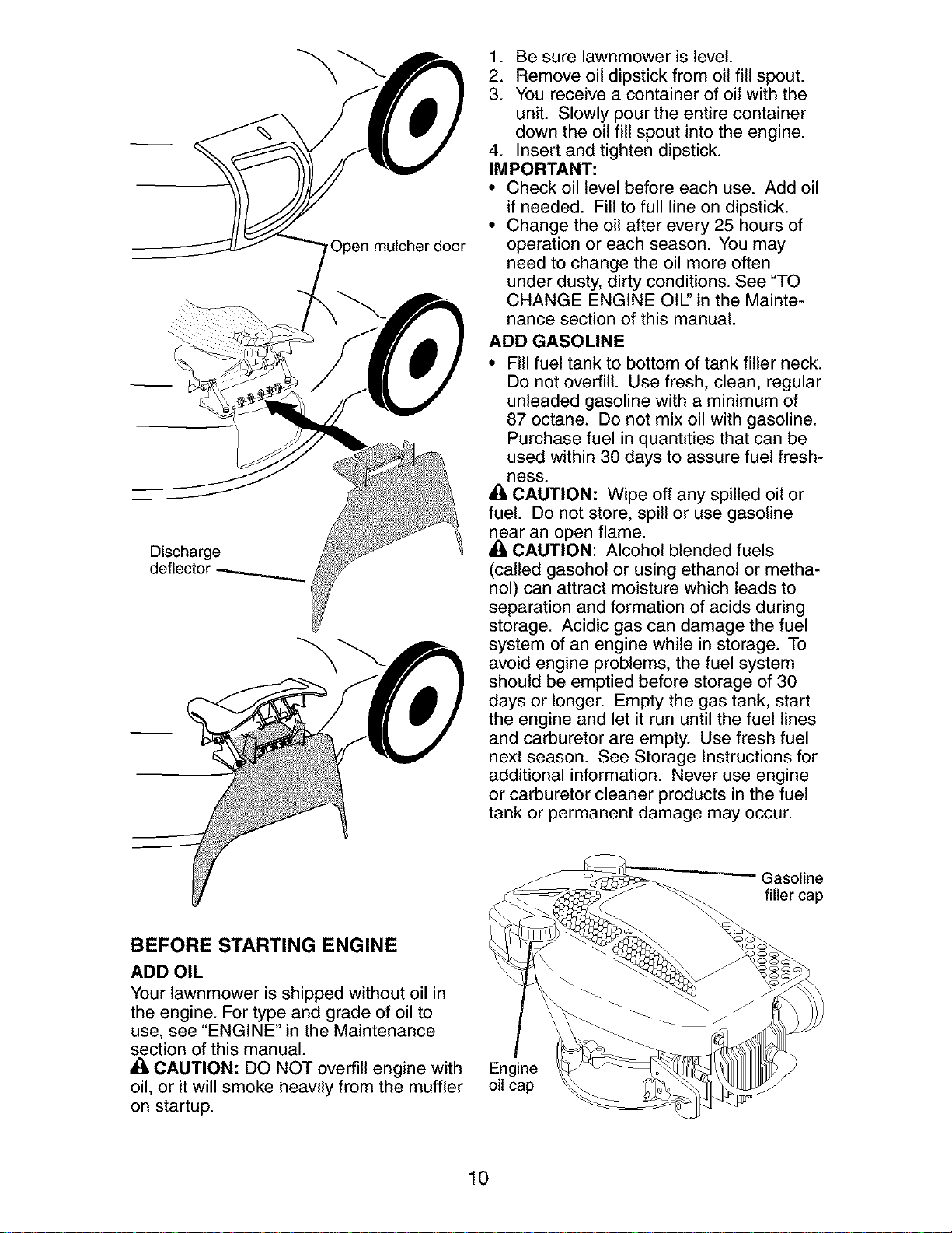
Open mulcher door
Discharge
deflector
BEFORE STARTING ENGINE
ADD OIL
Your lawnmower is shipped without oil in
the engine. For type and grade of oil to
use, see "ENGINE" in the Maintenance
section of this manual.
CAUTION: DO NOT overfill engine with
oil, or it will smoke heavily from the muffler
on startup.
1. Be sure lawnmower is level.
2. Remove oil dipstick from oil fill spout.
3. You receive a container of oil with the
unit. Slowly pour the entire container
down the oil fill spout into the engine.
4. Insert and tighten dipstick.
IMPORTANT:
• Check oil level before each use. Add oil
if needed. Fill to full line on dipstick.
• Change the oil after every 25 hours of
operation or each season. You may
need to change the oil more often
under dusty, dirty conditions. See "TO
CHANGE ENGINE OIE' in the Mainte-
nance section of this manual.
ADD GASOLINE
• Fill fuel tank to bottom of tank filler neck.
Do not overfill. Use fresh, clean, regular
unleaded gasoline with a minimum of
87 octane. Do not mix oil with gasoline.
Purchase fuel in quantities that can be
used within 30 days to assure fuel fresh-
Bess.
_1,CAUTION: Wipe off any spilled oil or
fuel. Do not store, spill or use gasoline
near
. an open flame.
CAUTION: Alcohol blended fuels
(called gasohol or using ethanol or metha-
nol) can attract moisture which leads to
separation and formation of acids during
storage. Acidic gas can damage the fuel
system of an engine while in storage. To
avoid engine problems, the fuel system
should be emptied before storage of 30
days or longer. Empty the gas tank, start
the engine and let it run until the fuel lines
and carburetor are empty. Use fresh fuel
next season. See Storage Instructions for
additional information. Never use engine
or carburetor cleaner products in the fuel
tank or permanent damage may occur.
Gasoline
filler cap
Engine
oil cap
10
TO STOP ENGINE
• To stop engine, release operator pres-
ence control bar.
NOTE: In cooler weather it may be neces-
sary to repeat priming steps. In warmer
weather over priming may cause flooding
and engine will not start. If you do flood
engine, wait a few minutes before attempt-
ing to start and do not repeat priming
steps.
TO START ENGINE
NOTE: Due to protective coatings on the
engine, a small amount of smoke may be
present during the initial use of the prod-
uct and should be considered normal.
1. To start a cold engine, push primer
three (3) times before trying to start.
Use a firm push. This step is not
usually necessary when starting an
engine which has already run for a few
minutes.
2. Hold operator presence control bar
down to the handle and pull starter
handle quickly. Do not allow starter
rope to snap back.
MOWING TIPS
• Under certain conditions, such as very
tall grass, it may be necessary to raise
the height of cut to reduce pushing
effort and to keep from overloading the
engine and leaving clumps of grass clip-
pings. It may also be necessary to re-
duce ground speed and/or run the lawn
mower over the area a second time.
• For extremely heavy cutting, reduce the
width of cut by overlapping previously
cut path and mow slowly.
• For better grass bagging and most cut-
ting conditions, the engine speed should
be set in the FAST position.
• Pores in cloth grass catchers can be-
come filled with dirt and dust with use
and catchers will collect less grass. To
prevent this, regularly hose catcher off
with water and let dry before using.
• Keep top of engine around starter clear
and clean of grass clippings and chaff.
This will help engine air flow and extend
engine life.
MULCHING MOWING TIPS
IMPORTANT: For best performance,
keep mower housing free of built-up
grass and trash. See "CLEANING" in the
Maintenance section of this manual.
• The special mulching blade will recut
the grass clippings many times and
reduce them in size so that as they fall
onto the lawn they will disperse into
the grass and not be noticed. Also, the
mulched grass will biodegrade quickly
to provide nutrients for the lawn. Always
mulch with your highest engine (blade)
speed as this will provide the best recut-
ting action of the blades.
• Avoid cutting your lawn when it is wet.
Wet grass tends to form clumps and
interferes with the mulching action. The
best time to mow your lawn is the early
afternoon. At this time the grass has
dried, yet the newly cut area will not be
exposed to direct sunlight.
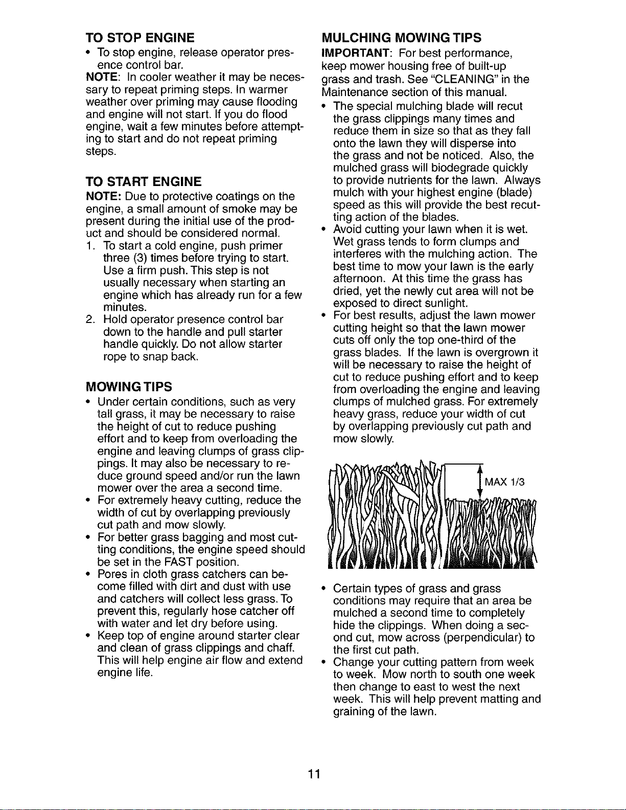
• For best results, adjust the lawn mower
cutting height so that the lawn mower
cuts off only the top one-third of the
grass blades. If the lawn is overgrown it
will be necessary to raise the height of
cut to reduce pushing effort and to keep
from overloading the engine and leaving
clumps of mulched grass. For extremely
heavy grass, reduce your width of cut
by overlapping previously cut path and
mow slowly.
MAXI_
• Certain types of grass and grass
conditions may require that an area be
mulched a second time to completely
hide the clippings. When doing a sec-
ond cut, mow across (perpendicular) to
the first cut path.
• Change your cutting pattern from week
to week. Mow north to south one week
then change to east to west the next
week. This will help prevent matting and
graining of the lawn.
11
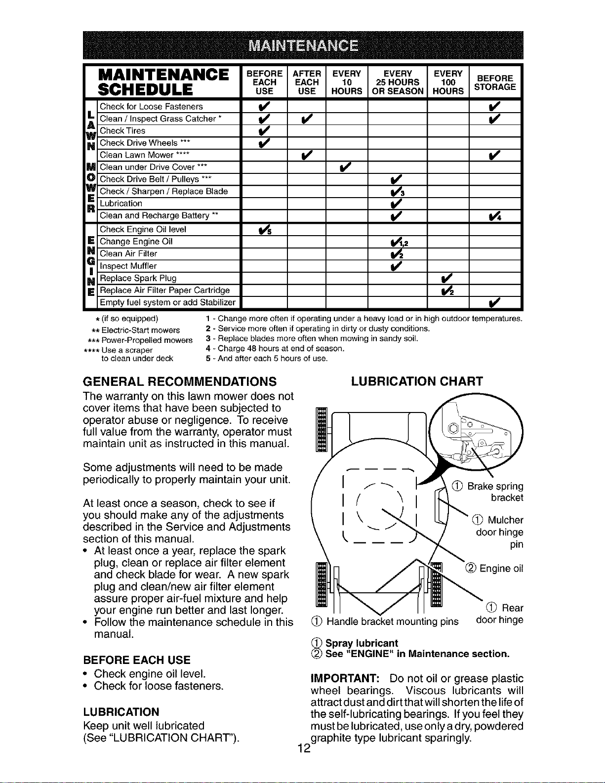
MAINTENANCE BEFOREAPTEREVERY EVERY EVERYBEFORE
EACH EACH 10 25HOURS 100
SCHEDULE USE USE HOURS ORSEASON HOURS STORAGE
Check for Loose Fasteners
AL Clean / Inspect Grass Catcher *
Check Tires
_ Check Drive Wheels
Clean Lawn Mower ....
M Clean under Drive Cover ***
O Check Drive Belt / Pulleys ***
_ Check / Sharpen / Replace Blade
R Lubrication
Clean and Recharge Battery **
Check Engine Oil level
E Change Engine Oil
_ Clean Air Filter
Inspect Muffler
_ Replace Spark Plug
E Replace Air Filter Paper Cartridge
Empty fuel system or add Stabilizer
i/ i/
i/
t/
t_,2
* (if so equipped)
** Electric-Start mowers
*** Power-Propelled mowers
**** Use a scraper
to clean under deck
1 - Change more often if operating under a heavy load or in high outdoor temperatures.
2 - Service more often if operating in dirty or dusty conditions.
3 - Replace blades more often when mowing in sandy soil.
4 - Charge 48 hours at end of season.
5 - And after each 5 hours of use.
GENERAL RECOMMENDATIONS
The warranty on this lawn mower does not
cover items that have been subjected to
operator abuse or negligence. To receive
full value from the warranty, operator must
maintain unit as instructed in this manual.
LUBRICATION CHART
Some adjustments will need to be made
periodically to properly maintain your unit.
At least once a season, check to see if
you should make any of the adjustments
described in the Service and Adjustments
section of this manual.
• At least once a year, replace the spark
plug, clean or replace air filter element
and check blade for wear. A new spark
plug and clean/new air filter element
assure proper air-fuel mixture and help
your engine run better and last longer.
• Follow the maintenance schedule in this
manual.
BEFORE EACH USE
• Check engine oil level.
• Check for loose fasteners.
LUBRICATION
Keep unit well lubricated
(See "LUBRICATION CHART").
I
I
I
f _'_ _ Brake spring
(' "_ bracket
\ _" Mulcher
j_, door hinge
pin
Handle bracket mounting pins
(_) Rear
door hinge
_ Spray lubricant
See "ENGINE" in Maintenance section.
IMPORTANT: Do not oil or grease plastic
wheel bearings. Viscous lubricants will
attract dust and dirt that will shorten the life of
the self-lubricating bearings. If you feel they
must be lubricated, use only a dry,powdered
2graphite type lubricant sparingly.
1

LAWN MOWER
Always observe safety rules when per-
forming any maintenance.
TIRES
• Keep tires free of gasoline, oil, or insect
control chemicals which can harm rubber.
• Avoid stumps, stones, deep ruts, sharp
objects and other hazards that may
cause tire damage.
DRIVE WHEELS
Check rear drive wheels each time you
mow to be sure they move freely. The
wheels not turning freely means trash,
grass cuttings, etc., may be inside the
drive wheel and dust cover area and must
be cleaned out to free drive wheels.
If necessary to clean the drive wheels,
check both rear wheels.
BLADE CARE
For best results, mower blade must be
kept sharp. Replace bent or damaged
blades.
TO REMOVE BLADE
1. Disconnect spark plug wire from spark
plug and place wire where it cannot
come in contact with plug.
2. Turn lawn mower on its side. Make
sure air filter and carburetor are up.
3. Use a wood block between blade and
mower housing to prevent blade from
turning when removing blade bolt.
NOTE: Protect your hands with gloves
and/or wrap blade with heavy cloth.
4. Remove blade bolt by turning counter-
clockwise.
5. Remove blade and attaching hard-
ware (bolt, lock washer and hardened
washer).
NOTE: Remove the blade adapter and
check the key inside hub of blade adapter.
The key must be in good condition to work
properly. Replace adapter if damaged.
TO REPLACE BLADE
1. Position the blade adapter on the en-
gine crankshaft. Be sure key in adapter
and crankshaft keyway are aligned.
2. Position blade on the blade adapter
aligning the two (2) holes in the blade
with the raised lugs on the adapter.
3. Be sure the trailing edge of blade (op-
posite sharp edge) is up toward the
engine.
4. Install the blade bolt with the lock
washer and hardened washer into
blade adapter and crankshaft.
5. Use block of wood between blade and
lawn mower housing and tighten the
blade bolt, turning clockwise.
• The recommended tightening torque is
35-40 ft. Ibs.
IMPORTANT: Blade bolt is heat treated.
If bolt needs replacing, replace only with
approved bolt shown in the Repair Parts
section of this manual.
Blade adapter Crankshaft
Key _ keyway
Blade
Blade shaft
bolt / \
washer Trailing edge Blade adapter
TO SHARPEN BLADE
NOTE: We do not recommend sharpening
blade - but if you do, be sure the blade is
balanced.
Care should be taken to keep the blade
balanced. An unbalanced blade will
cause eventual damage to lawn mower or
engine.
• The blade can be sharpened with a file
or on a grinding wheel. Do not attempt
to sharpen while on the mower.
• To check blade balance, drive a nail into
a beam or wall. Leave about one inch of
the straight nail exposed. Place center
hole of blade over the head of the nail.
If blade is balanced, it should remain in
a horizontal position. If either end of the
blade moves downward, sharpen the
heavy end until the blade is balanced.
GRASS CATCHER
• The grass catcher may be hosed with
water, but must be dry when used.
• Check your grass catcher often for dam-
age or deterioration. Through normal
use it will wear. If catcher needs replac-
ing, replace only with approved replace-
ment catcher shown in the Repair Parts
section of this manual. Give the lawn
mower model number when ordering.
13
ENGINE
LUBRICATION
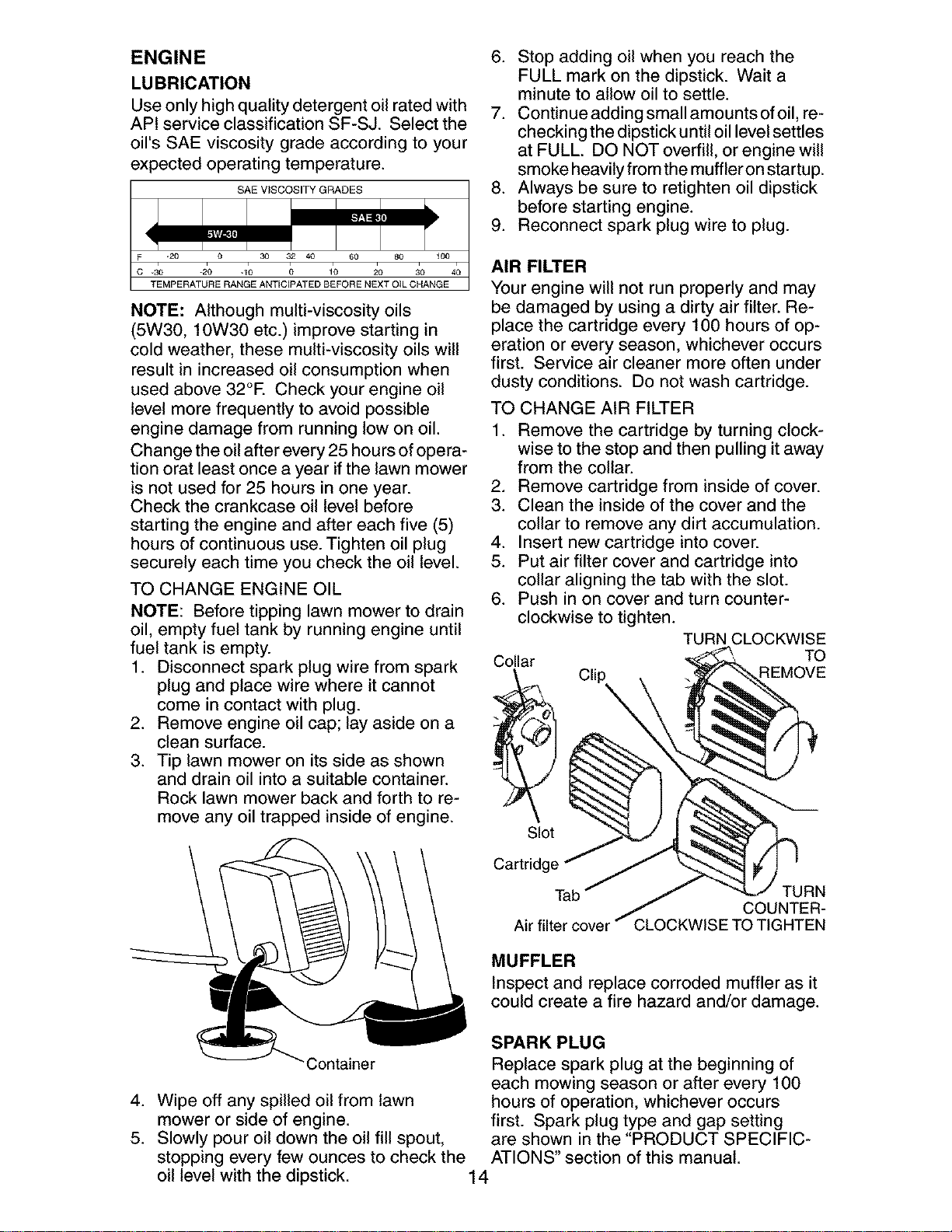
Use only high quality detergent oil rated with
API service classification SF-SJ. Select the
oil's SAE viscosity grade according to your
expected operating temperature.
SAE V_SCOSITY GRADES
-20 0 30 32 40 60 80 _00
.30 -20 .10 0 10 20 30 40
TEMPERATURE RANGE ANTICEPATED BEFORE NEXT OIL CHANGE
NOTE: Although multi-viscosity oils
(5W30, 10W30 etc.) improve starting in
cold weather, these multi-viscosity oils will
result in increased oil consumption when
used above 32°E Check your engine oil
level more frequently to avoid possible
engine damage from running low on oil.
Change the oil after every 25 hours of opera-
tion orat least once a year if the lawn mower
is not used for 25 hours in one year.
Check the crankcase oil level before
starting the engine and after each five (5)
hours of continuous use. Tighten oil plug
securely each time you check the oil level.
TO CHANGE ENGINE OIL
NOTE: Before tipping lawn mower to drain
oil, empty fuel tank by running engine until
fuel tank is empty.
1. Disconnect spark plug wire from spark tC°llar
plug and place wire where it cannot __
come in contact with plug.
2. Remove engine oil cap; lay aside on a
clean surface.
3. Tip lawn mower on its side as shown
and drain oil into a suitable container.
Rock lawn mower back and forth to re-
move any oil trapped inside of engine.
6. Stop adding oil when you reach the
FULL mark on the dipstick. Wait a
minute to allow oil to settle.
7. Continue adding small amounts of oil, re-
checking the dipstick until oil level settles
at FULL. DO NOT overfill, or engine will
smoke heavily from the muffler on startup.
8. Always be sure to retighten oil dipstick
before starting engine.
9. Reconnect spark plug wire to plug.
AIR FILTER
Your engine will not run properly and may
be damaged by using a dirty air filter. Re-
place the cartridge every 100 hours of op-
eration or every season, whichever occurs
first. Service air cleaner more often under
dusty conditions. Do not wash cartridge.
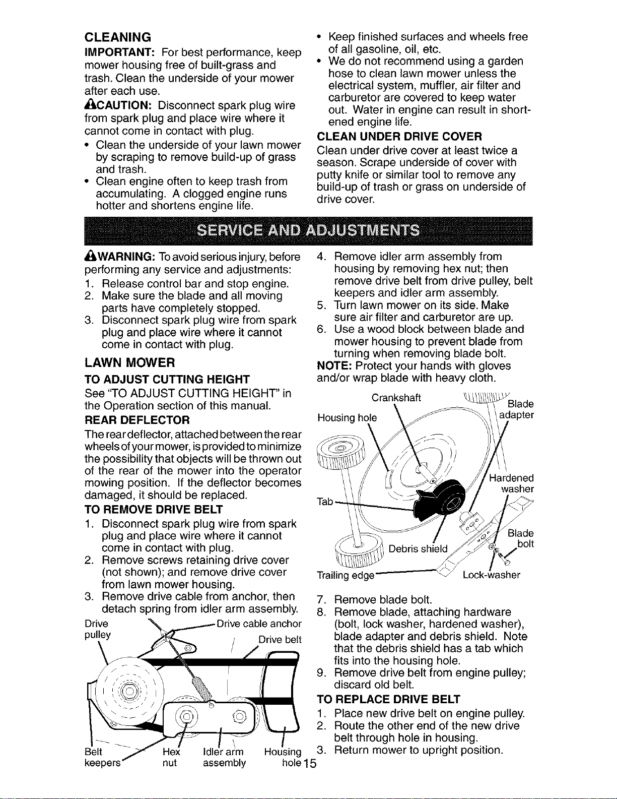
TO CHANGE AIR FILTER
1. Remove the cartridge by turning clock-
wise to the stop and then pulling it away
from the collar.
2. Remove cartridge from inside of cover.
3. Clean the inside of the cover and the
collar to remove any dirt accumulation.
4. Insert new cartridge into cover.
5. Put air filter cover and cartridge into
collar aligning the tab with the slot.
6. Push in on cover and turn counter-
clockwise to tighten.
TURN CLOCKWISE
Cli%
TO
REMOVE
Slot
Cartridge
Tab TURN
COUNTER-
Air filter cover CLOCKWISE TO TIGHTEN
MUFFLER
Inspect and replace corroded muffler as it
could create a fire hazard and/or damage.
3ontainer
4. Wipe off any spilled oil from lawn
mower or side of engine.
5. Slowly pour oil down the oil fill spout,
stopping every few ounces to check the
oil level with the dipstick.
SPARK PLUG
Replace spark plug at the beginning of
each mowing season or after every 100
hours of operation, whichever occurs
first. Spark plug type and gap setting
are shown in the "PRODUCT SPECIFIC-
ATIONS" section of this manual.
14
CLEANING
IMPORTANT: For best performance, keep
mower housing free of built-grass and
trash. Clean the underside of your mower
after each use.
_CAUTION: Disconnect spark plug wire
from spark plug and place wire where it
cannot come in contact with plug.
• Clean the underside of your lawn mower
by scraping to remove build-up of grass
and trash.
• Clean engine often to keep trash from
accumulating. A clogged engine runs
hotter and shortens engine life.
• Keep finished surfaces and wheels free
of all gasoline, oil, etc.
• We do not recommend using a garden
hose to clean lawn mower unless the
electrical system, muffler, air filter and
carburetor are covered to keep water
out. Water in engine can result in short-
ened engine life.
CLEAN UNDER DRIVE COVER
Clean under drive cover at least twice a
season. Scrape underside of cover with
putty knife or similar tool to remove any
build-up of trash or grass on underside of
drive cover.
ACIWARNING: To avoid serious injury, before
performing any service and adjustments:
1. Release control bar and stop engine.
2. Make sure the blade and all moving
parts have completely stopped.
3. Disconnect spark plug wire from spark
plug and place wire where it cannot
come in contact with plug.
LAWN MOWER
TO ADJUST CUTTING HEIGHT
See "TO ADJUST CUTTING HEIGHT' in
the Operation section of this manual.
REAR DEFLECTOR
The rear deflector, attached between the rear
wheels ofyour mower, isprovided to minimize
the possibility that objects will be thrown out
of the rear of the mower into the operator
mowing position. If the deflector becomes
damaged, it should be replaced.
TO REMOVE DRIVE BELT
1. Disconnect spark plug wire from spark
plug and place wire where it cannot
come in contact with plug.
2. Remove screws retaining drive cover
(not shown); and remove drive cover
from lawn mower housing.
3. Remove drive cable from anchor, then
detach spring from idler arm assembly.
Drive anchor
pulley
Drive belt
4. Remove idler arm assembly from
housing by removing hex nut; then
remove drive belt from drive pulley, belt
keepers and idler arm assembly.
5. Turn lawn mower on its side. Make
sure air filter and carburetor are up.
6. Use a wood block between blade and
mower housing to prevent blade from
turning when removing blade bolt.
NOTE: Protect your hands with gloves
and/or wrap blade with heavy cloth.
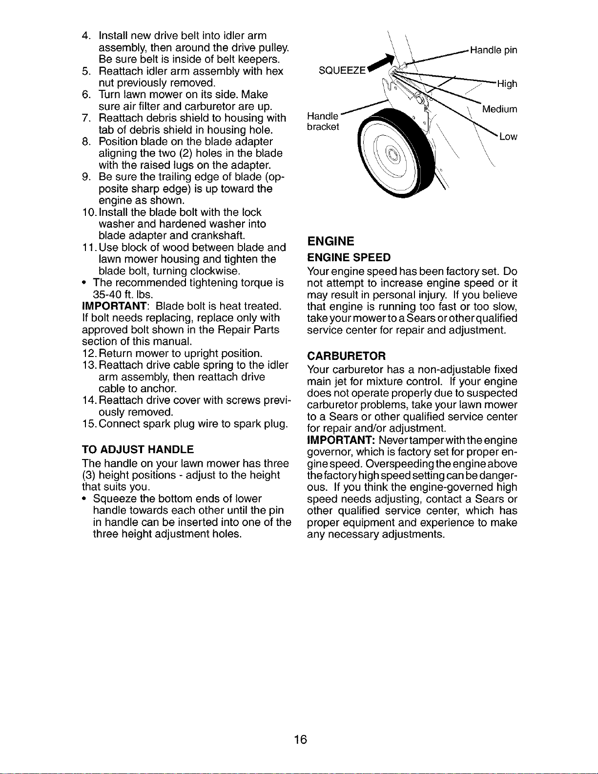
Crankshaft
Housing hole
Tab-
Hardened
washer
Debris shield
Blade
bolt
7. Remove blade bolt.
8. Remove blade, attaching hardware
(bolt, lock washer, hardened washer),
blade adapter and debris shield. Note
that the debris shield has a tab which
fits into the housing hole.
9. Remove drive belt from engine pulley;
discard old belt.
Belt r arm
nut assembly
TO REPLACE DRIVE BELT
1. Place new drive belt on engine pulley.
2. Route the other end of the new drive
belt through hole in housing.
Housing 3. Return mower to upright position.
hole15
4. Installnewdrivebelt intoidlerarm
assembly,thenaroundthe drivepulley.
Besurebelt isinsideof beltkeepers.
5. Reattachidlerarmassemblywith hex
nutpreviouslyremoved.
6. Turnlawnmoweron itsside.Make
sureairfilter andcarburetorareup.
7. Reattachdebrisshieldto housingwith
tabof debrisshieldin housinghole.
8. Positionbladeon thebladeadapter
aligningthetwo(2)holesinthe blade
withthe raisedlugson theadapter.
9. Besurethetrailingedgeof blade(op-
positesharpedge)isup towardthe
engineasshown.
10.Installthe bladebolt withthe lock
washerand hardenedwasherinto
bladeadapterandcrankshaft.
11.Useblockof woodbetweenbladeand
lawnmowerhousingandtightenthe
bladebolt,turningclockwise.
• Therecommendedtighteningtorqueis
35-40ft. Ibs.
IMPORTANT:Bladeboltis heattreated.
Ifbolt needsreplacing,replaceonlywith
approvedboltshownin the RepairParts
sectionofthismanual.
12.Returnmowerto uprightposition.
13.Reattachdrivecablespringto the idler
armassembly,thenreattachdrive
cableto anchor.
14.Reattachdrivecoverwithscrewsprevi-
ouslyremoved.
15.Connectspark plugwireto sparkplug.
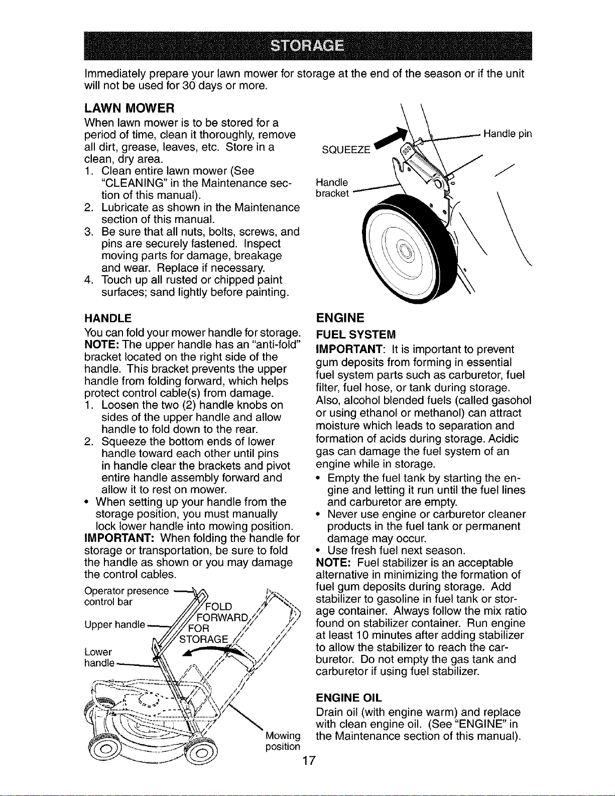
TO ADJUST HANDLE
The handle on your lawn mower has three
(3) height positions - adjust to the height
that suits you.
• Squeeze the bottom ends of lower
handle towards each other until the pin
in handle can be inserted into one of the
three height adjustment holes.
SQL
pin
bracket
Medium
ENGINE
ENGINE SPEED
Your engine speed has been factory set. Do
not attempt to increase engine speed or it
may result in personal injury. If you believe
that engine is running too fast or too slow,
take you rmower to a Sears or other qualified
service center for repair and adjustment.
CARBURETOR
Your carburetor has a non-adjustable fixed
main jet for mixture control. If your engine
does not operate properly due to suspected
carburetor problems, take your lawn mower
to a Sears or other qualified service center
for repair and/or adjustment.
IMPORTANT: Never tamper with the engine
governor, which is factory set for proper en-
gine speed. Overspeeding the engine above
the factory high speed setting can bedanger-
ous. If you think the engine-governed high
speed needs adjusting, contact a Sears or
other qualified service center, which has
proper equipment and experience to make
any necessary adjustments.
16
Immediately prepare your lawn mower for storage at the end of the season or if the unit
will not be used for 30 days or more.
LAWN MOWER
When lawn mower is to be stored for a
period of time, clean it thoroughly, remove
all dirt, grease, leaves, etc. Store in a
clean, dry area.
1. Clean entire lawn mower (See
"CLEANING" in the Maintenance sec-
tion of this manual).
2. Lubricate as shown in the Maintenance
section of this manual.
3. Be sure that all nuts, bolts, screws, and
pins are securely fastened. Inspect
moving parts for damage, breakage
and wear. Replace if necessary.
4. Touch up all rusted or chipped paint
surfaces; sand lightly before painting.
SQUEEZE
Handle
bracket
Handle pin
J
HANDLE
You can fold your mower handle for storage.
NOTE: The upper handle has an "anti-fold"
bracket located on the right side of the
handle. This bracket prevents the upper
handle from folding forward, which helps
protect control cable(s) from damage.
1. Loosen the two (2) handle knobs on
sides of the upper handle and allow
handle to fold down to the rear.
2. Squeeze the bottom ends of lower
handle toward each other until pins
in handle clear the brackets and pivot
entire handle assembly forward and
allow itto rest on mower.
• When setting up your handle from the
storage position, you must manually
lock lower handle into mowing position.
IMPORTANT: When folding the handle for
storage or transportation, be sure to fold
the handle as shown or you may damage
the control cables.
Operator presence
control bar
Lower
ENGINE
FUEL SYSTEM
IMPORTANT: It is important to prevent
gum deposits from forming in essential
fuel system parts such as carburetor, fuel
filter, fuel hose, or tank during storage.
Also, alcohol blended fuels (called gasohol
or using ethanol or methanol) can attract
moisture which leads to separation and
formation of acids during storage. Acidic
gas can damage the fuel system of an
engine while in storage.
• Empty the fuel tank by starting the en-
gine and letting it run until the fuel lines
and carburetor are empty.
• Never use engine or carburetor cleaner
products in the fuel tank or permanent
damage may occur.
• Use fresh fuel next season.
NOTE: Fuel stabilizer is an acceptable
alternative in minimizing the formation of
fuel gum deposits during storage. Add
stabilizer to gasoline in fuel tank or stor-
age container. Always follow the mix ratio
found on stabilizer container. Run engine
at least 10 minutes after adding stabilizer
to allow the stabilizer to reach the car-
buretor. Do not empty the gas tank and
carburetor if using fuel stabilizer.
ENGINE OIL
Mowing
position
Drain oil (with engine warm) and replace
with clean engine oil. (See "ENGINE" in
the Maintenance section of this manual).
17
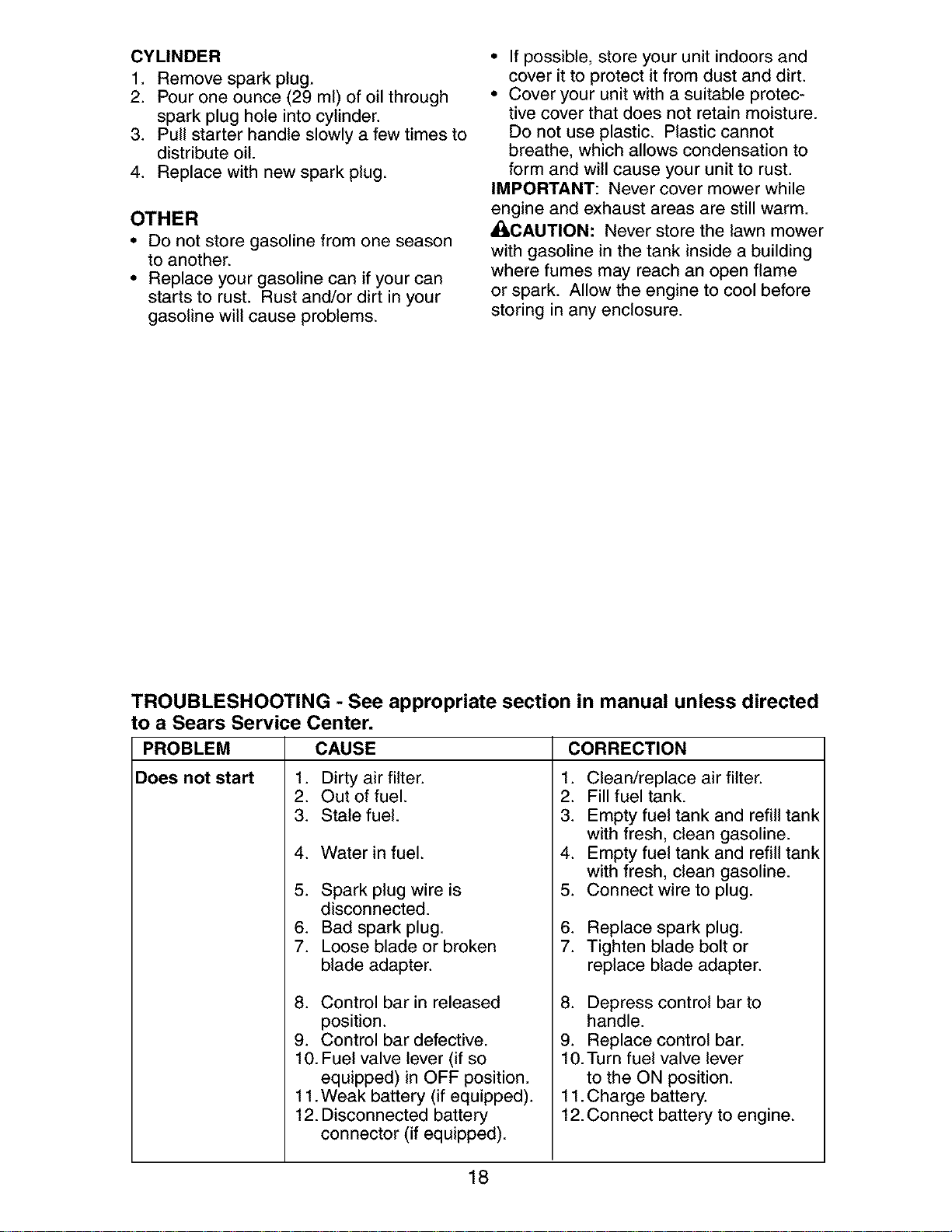
CYLINDER
1. Remove spark plug.
2. Pour one ounce (29 ml) of oil through
spark plug hole into cylinder.
3. Pull starter handle slowly a few times to
distribute oil.
4. Replace with new spark plug.
OTHER
• Do not store gasoline from one season
to another.
• Replace your gasoline can if your can
starts to rust. Rust and/or dirt in your
gasoline will cause problems.
• If possible, store your unit indoors and
cover it to protect it from dust and dirt.
• Cover your unit with a suitable protec-
tive cover that does not retain moisture.
Do not use plastic. Plastic cannot
breathe, which allows condensation to
form and will cause your unit to rust.
IMPORTANT: Never cover mower while
engine and exhaust areas are still warm.
_[I,CAUTION: Never store the lawn mower
with gasoline in the tank inside a building
where fumes may reach an open flame
or spark. Allow the engine to cool before
storing in any enclosure.
TROUBLESHOOTING - See appropriate section in manual unless directed
to a Sears Service Center.
PROBLEM CAUSE CORRECTION
Does not start
1. Dirty air filter.
2. Out of fuel.
3. Stale fuel.
4. Water in fuel.
5. Spark plug wire is
disconnected.
6. Bad spark plug.
7. Loose blade or broken
blade adapter.
8. Control bar in released
position.
9. Control bar defective.
10. Fuel valve lever (if so
equipped) in OFF position.
11.Weak battery (if equipped).
12. Disconnected battery
connector (if equipped).
2.
3.
4.
5.
6.
7.
Clean/replace air filter.
Fill fuel tank.
Empty fuel tank and refill tank
with fresh, clean gasoline.
Empty fuel tank and refill tank
with fresh, clean gasoline.
Connect wire to plug.
Replace spark plug.
Tighten blade bolt or
replace blade adapter.
8. Depress control bar to
handle.
9. Replace control bar.
10.Turn fuel valve lever
to the ON position.
11.Charge battery.
12.Connect battery to engine.
18

TROUBLESHOOTING - See appropriate section in manual unless directed
to a Sears Service Center.
PROBLEM CAUSE
Loss of power 1. Rear of lawn mower
Poor cut -
uneven
Excessive
vibration
Starter rope
hard to pull
CORRECTION
1. Raise cutting height.
2. Raise cutting height.
3. Clean/replace air filter.
4. Clean underside of mower
housing.
5. Check oil level.
6. Cut at slower walking speed.
housing or cutting blade
dragging in heavy grass.
2. Cutting too much grass.
3. Dirty air filter.
4. Buildup of grass, leaves,
and trash under mower.
5. Too much oil in engine.
6. Walking speed too fast.
1. Worn, bent or loose blade.
2. Wheel heights uneven.
3. Buildup of grass, leaves
and trash under mower.
1. Worn, bent or loose blade.
2. Bent engine crankshaft.
1. Engine flywheel brake is on
when control bar is released.
2. Bent engine crankshaft.
3. Blade adapter broken.
4. Blade dragging in grass.
Cutting height too low.
Lift on blade worn off.
Catcher not venting air.
Grass is too high or wheel
height is too low.
2. Rear of lawn mower
housing or cutting blade
dragging in grass.
3. Grass catcher too full.
4. Handle height position not
right for you.
1. Belt wear.
2. Belt off of pulley.
3. Drive cable worn or broken.
4. "Loose" drive control system.
1. Replace blade. Tighten
blade bolt.
2. Set all wheels at same
height.
3. Clean underside of
mower housing.
1. Replace blade. Tighten
blade bolt.
2. Contact a Sears or other
qualified service center.
1. Depress control bar to
upper handle before
pulling starter rope.
2. Contact a Sears or other
qualified service center.
3. Replace blade adapter.
4. Move lawn mower to cut
grass or to hard surface.
Grass catcher 1. 1. Raise cutting height.
not filling 2. 2. Replace blade.
(If so equipped) 3. 3. Clean grass catcher.
Hard to push 1. 1. Raise cutting height.
Loss of drive
or slowing of
drive speed
2. Raise rear of lawn mower
housing one (1) setting
higher.
3. Empty grass catcher.
4. Adjust handle height to suit.
1. Check/replace drive belt.
2. Check/reinstall drive belt.
3. Replace drive cable.
4. Adjust drive control.
19
Garantia ......................................................... 20
Reglas de Seguridad ................................ 20-22
Especificaciones del Producto ....................... 22
Montaje / Pre-Operaci6n ............................... 24
Operaci6n ................................................. 25-29
Mantenimiento .......................................... 30-33
Programa de Mantenimiento ......................... 30
Servicio y Adjustes ................................... 33-34
Almacenamiento ....................................... 35-36
Identificaci6n de problemas ...................... 36-37
Partes de repuesto .................................. 38-45
Servicio Sears .................................. Contratapa
GARANTiA LIMITADA DE DOS AI_IOS PARA LA SEGADORA A MOTOR CRAFTSMAN
Per dos (2) aSos, a partir de la fecha de compra, cuando esta Segadora Craftsman se mantenga,
lubrique y afine segSn las instrucciones para la operaci6n y el mantenimiento en el manual del
dueSo, Sears repararA gratis todo defecto en el material y la mane de obra.
Si la Segadora Craftsman se usa para fines comerciates o de arriendo, esta garantia s61ose aplica
per noventa (90) dias a partir de la fecha de compra.
Esta Garantia no cubre:
• Arficulos que se desgastan durante el use normal tales come las cuchillas segadoras rotatorias,
los adaptadores de la cuchilla, las correas, los filtros de aire y las bujias.
• Reparaciones necesarias debido al abuse o a la negligencia del operador, incluy_ndose a los
cigeeSales doblados y a la falta de mantenimiento del equipo segSn las instrucciones que se
inctuyen en el manual del dueSo.
El servicio de garantfa esta disponible al devolver la segadora a motor Craftsman al Centro/Depart-
mento de Servicio Sears mas cercano en los Estados Unidos. Esta garantia se aplica solamente
mientras el producto este en use en los Estados Unidos.
Esta Garanfia le otorga derechos legales especfficos, y puede que tambi6n tenga otros derechos
que varfan de estado a estado.
Sears, Roebuck and Co., D/817WA, Hoffman Estates, IL 60179 USA
IMPORTANTE: Esta maquina cortadaora es capaz de amputar las manes y los manes y los pies y
de lanzar objetos. Si no se observan las instrucciones de seguridad siguientes se pueden producir
lesiones graves o la muerte.
_Busque este sfmbolo que sefala las precau-
ciones de seguridad de importancia. Quiere
decir - i iiATENCION!% iESTE ALERTO!!!
SU SEGURIDAD ESTA COMPROMETIDA.
d_had)VERTENClA: Siempre desconecte el
alambre de la bujfa y p6ngato donde no pueda
entrar en contacto con la bujfa, para evitar et
arranque per accidente, durante la preparaci6n,
el transporte, el ajuste o cuando se hacen
reparaciones.
_DVERTENClA: Los bornes, terminales y
accesorios relatives de la bateria contienen
plomo o compuestos de plomo, productos
qufmicos conocidos en el Estado de California
come causa de cancer y defectos al nacimiento
u otros daSos reproductivos. Lavar lae manes
despu_e de manipularloe.
_[ILPRECAUCI(_N: El tube de escape del motor,
algunos de sus constituyentes y algunos com-
ponentes del vehfculo contienen o desprenden
productos qufmicos conocidos en el Estado de
California come causa de cancer y defectos at
nacimiento u otros daSos reproductivos.
_PRECAUCl0N: El silenciador y otras
piezas del motor llegan a sre extremadamente
calientes durante la operaci6n y siguen siendo
calientes despu_s de que el motor haya parade.
Para evitar quemaduras severas, permanezca
lejos de estas Areas.
20
I. OPERAClON
• Antes de empezar, debe familiarizarse comple-
tamente con los controles y el uso correcto de
la maquina. Para esto, debe leer y comprender
todas las instrucciones que aparecen en la ma-
quina yen los manuales de operaci6n.
• No ponga las manos o los pies cerca o
debajo de las partes rotatorias. Mant6ngase
siempre lejos de la abertura de la descarga.
• Permita que solamente las personas re-
sponsables que est6n familiarizadas con las
instrucciones operen la mAquina.
• Despeje el Area de objetos tales como pie-
dras, juguetes, alambres, huesos, palos, etc.
que pueden ser recogidos y lanzados por las
cuchillas.
• AsegSrese que el Area no se hallen per-
sonas, antes de segar. Pare la mAquina si
alguien entra en el Area.
• No opere la maquina sin zapatos o con sanda-
lias abiertas. P6ngase siempre zapatos s61idos.
• No tire de la segadora hacia atrAs a menos
que sea absolutamente necesado. Mire
siempre hacia abajo y hacia detrAs antes y
mientras que se mueve hacia atrAs.
• No opere la segadora sin los respectivos
resguardos, las placas, el recogedor de
c6sped u otros aditamentos dise ados para
su protecci6n y seguridad.
• Refi_rase alas instrucciones det fabricante
para el funcionamiento e instataci6n de
accesorios. Use t_nicamente accesorios
aprobados por el fabricante.
• Detenga la cuchilla o las cuchillas cuando cruce
por catzadas, calles o caminos de grava.
• Parar el motor cada vez que se abandona el
aparato, antes de limpiar la segadora o de
remover residuos del tubo.
• Apagar el motor y esperar hasta que las
cuchillas est_n completamente paradas
antes de remover el receptor de hierba.
• Segar solamente con luz del dfa o con una
buena luz artificial.
• No opere la mAquina bajo la influencia del
alcohol o de las drogas.
• Nunca opere la maquina cuando la hierba
est_ mojada. Asegt]rese siempre de tener
buena tracci6n en sus pies; mantenga el
mango firmemente y camine; nunca corra.
• Desconectar el mecanismo de propulsi6n
aut6noma o el embrague de transmisi6n en
las segadoras que Io tienen antes de poner
en marcha el motor.
• Si el equipo empezara a vibrar de una
manera anormal, pare el motor y revise de
inmediato para averiguar la causa. General-
mente la vibraci6n suele indicar que existe •
alguna averia.
• Siempre use gafas de seguridad o anteojos con •
protecci6n lateral cuando opere la segadora.
II. OPERACION SOBRE LAS CUESTAS
Los accidentes ocurren con mAs frecuencia en
las cuestas. Estos accidentes ocurren debido a
resbaladas o caidas, las cuales pueden resultar •
en graves lesiones. Operar la recortadora en
cuestas requiere mayor concentraci6n. Si se
siente inseguro en una cuesta, no la recorte.
21
HACER:
• Puede recortar a trav6s de la superficie de
la cuesta, nunca hacia ardba y hacia abajo.
Proceda con extrema precauci6n cuando
cambie de direcci6n en las cuestas.
• Renueva todos los objetos extraSos, tales
como guijarros, ramas, etc.
• Debe prestar atenci6n a hoyos, baches o
protuberancias. Recuerde que la hierba alta
puede esconder obstAculos.
NO HACER:
• No recorte cerca de pendientes, zanjas o
terraplenes. El operador puede perder la
tracci6n en los pies o el equilibrio.
• No recorte cuestas demasiado inclinadas.
• No recorte en hierba mojada. La reducci6n
en la tracci6n de la pisada puede causar
resbalones.
III. NINOS
Se pueden producir accidentes trAgicos si el
operador no presta atenci6n a la presencia
de los niSos. A menudo, los niSos se sienten
atraidos por la maquina y por la actividad de
la siega. Nunca suponga que los niSos van a
permanecer en el mismo lugar donde los vio
por _ltima vez.
• Mantenga a los niSos alejados del Area de
la siega y bajo el cuidado estricto de otra
persona adulta responsable.
• Est6 alerta y apague la maquina si hay niSos
que entran at Area.
• Antes y cuando este retrocediendo, mire
hacia atrAs y hacia abajo para verificar si hay
niSos pequeSos.
• Nunca permita que los ni_os operen la mAquina.
• Tenga un cuidado extra cuando se acerque
a esquinas donde no hay visibilidad, a los
arbustos, Arboles u otros objetos que pueden
interferir con su linea de visi6n.
IV. SERMIClO
• Tenga cuidado extra al manejar la gasolina y
los demAs combustibles. Son inflamables y
los gases son explosivos.
- Use solamente un envase aprobado.
- Nunca remueva la tapa del dep6sito de
gasolina o agregue combustible con el mo-
tor funcionando. Permita que el motor se
enfrfe antes de volver a pone combustible.
No fume.
- Nunca vuelva a poner combustible en la
mAquina en recintos cerrados.
- Nunca almacene la mAquina o el envase
del combustible dentro de algt]n lugar en
donde haya una llama expuesta, tat como
la del calentador de agua.
Nunca haga funcionar una mAquina dentro
de un Area cerrada.
Nunca haga ajustes o reparaciones mientras
el motor est_ en marcha. Desconecte et
cable de la bujfa, y mant_ngalo a cierta
distancia de 6sta para prevenir un arranque
accidental.
Mantenga las tuercas y los pernos, espe-
cialmente los pernos del accesorio de la
cuchilla, apretados y mantenga el equipo en
buenas condiciones.
• Nuncamanipuledeformaindebidalos
dispositivosdeseguridad.Controleregular-
mentesufuncionamientocorrecto.
• Mantengalam&quinalibredehierba,hojas
uotrasacumulacionesdedesperdicio.
Limpielosderramesdeaceiteocombustible.
Permitaquelam&quinaseenfrfeantesde
almacenarla.
• Pareeinspeccioneelequiposilepegaaun
objeto.Rep&relo,siesnecesario,antesde
hacerloarrancar.
• Enningt]ncasohayqueregularlaalturade
lasruedasmientraselmotorestAenmarcha.
• Loscomponentesdelreceptordelahierba
vansujetosadesgaste,daSosydetedoro,
quepuedenexponerlaspartesenmov-
imientoopermitirqueobjetosseandispara-
dos.Controlarfrecuentementeycuandosea
necesadosustituirconpartesaconsejadas
perelfabricante.
• Lascuchillasdelasegadoraest#,nafiladasy
puedencortar.Cubrirlashojasollevarguantes,
y utilizarprecaucionesespecialescuandose
efectt_amantenimientosobrelasmismas.
• Nocambieelajustedelreguladordelmotor
niexcedasuvelocidad.
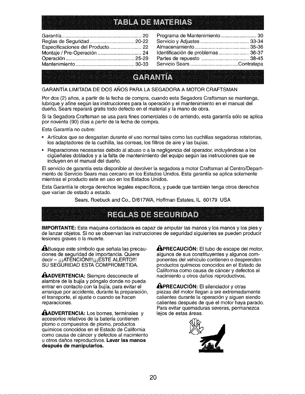
Nt_mero de Serie:
Fecha de Compra:
Capacidad y Tipo de Gasolina: 1.6 Cuartos (Regular sin Plomo)
Tipo de Aceite (API-SF-SJ): SAE 30 (Sobre 32°F); SAE 5W-30 (Debajo 32°F)
Capacidad de Aceite: 20 Onzas
Bujfa (Abertura: .030") Champion RJ19LM o J19LM
Torsi6n del Perno de la Cuchilla: 35-40 ft. Ibs.
• El nt]mero del nodelo y el de serie se encuentran en la calcomania adjunta a la parte trasera
de ta caja de la segadora. Debe registrar tanto el nQmero de serie come la fecha de compra y
mantengatos en un lugar seguro para refencia en el futuro.
Acuerdos de Protecci6n para la Reparaci6n
Congratulaciones por su buena compra. Su
nuevo producto Craftsman® estA diseSado
y fabricado para funcionar de modo fiable por
muchos aSos. Pero como todos los productos,
puede necesitar alguna reparaci6n de tanto
en tanto. En este caso tener un Acuerdo de
Protecci6n para la Reparaci6n puede hacerles
ahorrar dinero y fastidios.
Compre ahora un Acuerdo de ProtecciSn para
la ReparaciSn y prot&gese de molestias y gas-
tos inesperados.
Un Acuerdo incluye los punto$ $iguientes:
• Servicio experto de nuestros 12.000 espe-
cialistas profesionales en la reparaci6n.
• Servicio ilimitado sin cargo alguno para
las partes y ta mano de obra sobre todas las
reparaciones garantizadas.
• Sustitucion del producto si su producto
garantizado no puede ser arreglado.
• Descuento de110% sobre el precio cor-
riente del servicio y de las partes relativas al
servicio no cubiertas por el acuerdo; tambi_n
el 10% menos sobre el precio corriente de
un control de mantenimiento preventive.
• Ayuda rapida por telefono - soporte tele-
f6nico per parte de un t6cnico Sears sobre
productos que requieren un arreglo en casa,
y adem#,s una programaci6n sobre los a
reglos mAs convenientes.
Cuando se ha comprado el Acuerdo, basta con
una Ilamada telef6nica para programar el servi-
cio. Puede Ilamar cuando quiera, alia y noche o
fijar en linea una cita para obtener el servicio.
Sears tiene m#,s de 12.000 especialistas
profesionales en la reparaci6n, que tienen
acceso a mAs de 4.5 millones de partes y
accesorios de calidad. Este es el tipo de
profesionalidad con que puede contar para
ayudar a alargar la vida det producto que acaba
de comprar, por muchos aSos. iCompre hoy su
Acuerdo de Protecci6n para la Reparaci6n!
Se aplican algunas limitaciones y exclu-
siones. Para conocer los precios y tener
mas informacion, Ilame al 1-800-827-6655.
Servicio de Instalacibn Sears
Para la instalaci6n profesional Sears de
aparatos de casa, puertas de garaje,
calentadores de agua y otros importantes
artfculos para ta casa, en U.S.A. Ilamar a
1-8OO-4-MY-HOME®.
22
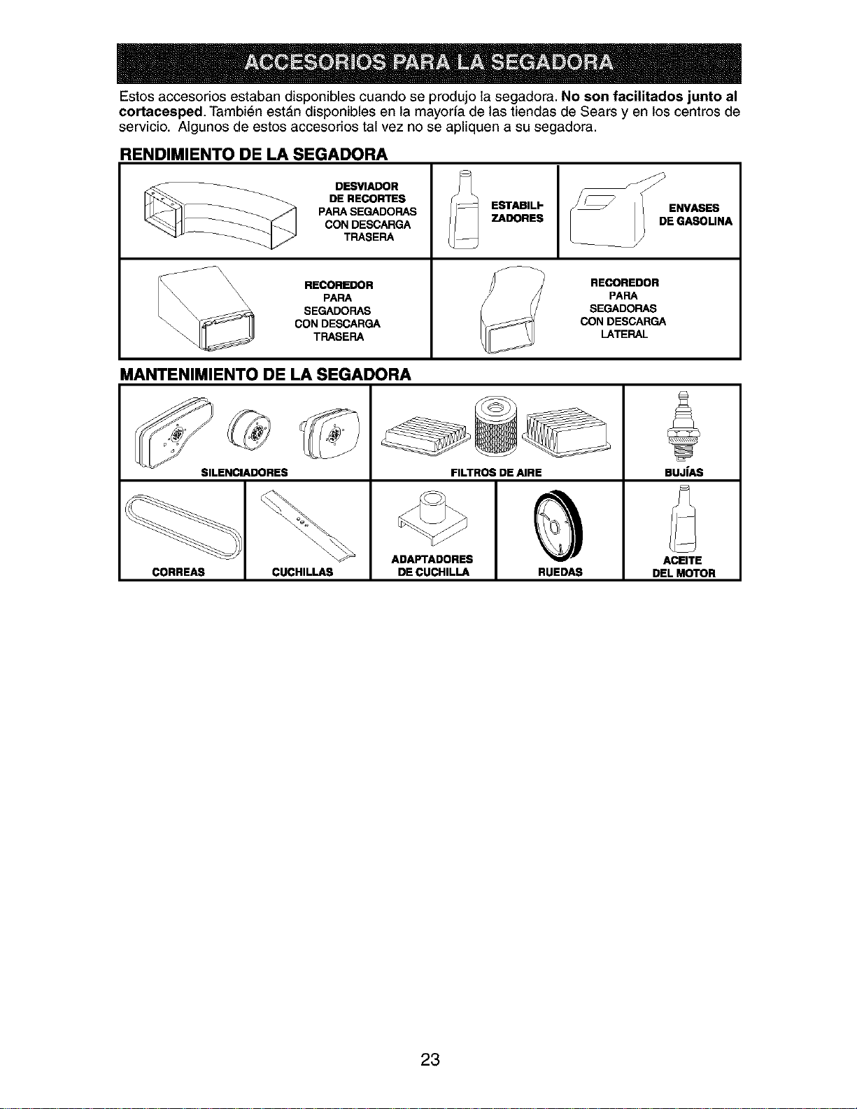
Estos accesorios estaban disponibles cuando se produjo la segadora. No son facilitados junto al
¢ortacesped. Tambi6n estAn disponibles en la mayoria de las tiendas de Sears yen los centros de
servicio. Algunos de estos accesorios tal vez no se apliquen a su segadora.
RENDIMIENTO DE LA SEGADORA
\\ \
\
DESVIADOR
DE RECORTES
PAPA SEGADOFIAS
CON DESCARGA
TRASERA
RECOREnOR
PAPA
SEGADOFIAS
CON DESCARGA
TFIASEFIA
ESTABILI-
ZADORES
RECOREDOR
PAPA
SEGADORAS
CON DESCARGA
LATERAL
MANTENIMIENTO DE LA SEGADORA
SILENCIADORES FILTROS DE AIRE BUJIAS
ADAPTADORES ACEITE
CORREAS CUCHILLAS DE CUCHILLA RUEDAS DEL MOTOR
23
Lea estas instrucciones y este manual comple-
tamente antes de tratar de montar u operar su
segadora nueva.
IMPORTANTE: Este cortac6sped viene SIN
ACEITE O GASOLINA en el motor.
Su segadora nueva ha side montada en la
f&brica con la excepci6n de aquellas partes que
se dejaron sin montar por razones de envio.
Todas tas partes como las tuercas, tas arande-
las, los pernos, etc., que son necesadas para
completar el montaje han side colocadas en la
bolsa de partes. Para asegurarse que su sega-
dora funcione en forma segura y adecuada,
todas las partes y los arficulos de ferreteria que
se monten tienen que ser apretados segura-
mente. Use las herramientas correctas, como
sea necesario, para asegurar que se aprieten
adecuadamente.
PARA REMOVER LA SEGADORA DE
LA CAJA DE CARTON
1. Remueva las partes sueltas que se incluyen
con la segadora.
2. Corte las dos esquinas de los extremos
de la caja de cart6n y tienda el panel del
extremo piano.
3. Remueva todo el material de empaque, ex-
cepto la curia entre el mango superior y 61 Soporte de
inferior, y la curia que sujeta la barra de los mango
control que exige la presencia del operador
junto con el mango superior.
4. Haga rodar la segadora hacia afuera de la
caja de cart6n y revisela cuidadosamente
para verificar si todavia quedan partes
sueltas adicionales.
COMO PREPARAR SU SEGADORA
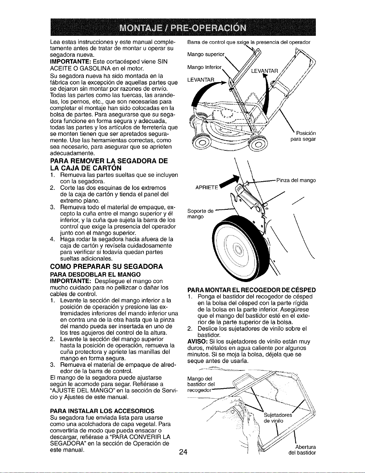
PARA DESDOBLAR EL MANGO
IMPORTANTE: Despliegue el mango con
mucho cuidado para no pellizcar o dafiar los
cables de control.
1. Levante la secci6n del mango inferior a la
posici6n de operaci6n y presione las ex-
tremidades inferiores del mando inferior una
en contra una de la otra hasta que la pinza
det mando pueda ser insertada en uno de
los tres agujeros del control de ta altura.
2. Levante la secci6n del mango superior
hasta la posici6n de operaci6n, remueva la
curia protectora y apdete las manillas del
mango en forma segura.
3. Remueva et material de empaque de alred-
edor de la barra de control.
El mango de la segadora puede ajustarse Mangodel
seg_n le acomode para segar. Refi6rase a bastidor del
"AJUSTE DEL MANGO" en la secci6n de Servi- recogedor
cioy Ajustes de este manual.
PARA INSTALAR LOS ACCESORIOS
Su segadora rue enviada lista para usarse
como una acolchadora de capa vegetal. Para
convertirla de mode que pueda ensacar o
descargar, refi6rase a "PARA CONVERIR LA
SEGADORA" en la secci6n de Operaci6n de
este manual.
Barra de control c
Mango superior
Mango Inferior
LEVANTAR
la presencia del operador
Posici6n
para segar
a del mango
J
PARA MONTAR EL RECOGEDOR DE ClaSPED
1. Ponga el bastidor del recogedor de c6sped
en la bolsa del c6sped con la parte rfgida
de la bolsa en la parte inferior. Asegt]rese
que el mango del bastidor est6 en el exte-
rior de la parte superior de la bolsa.
2. Destice los sujetadores de vinilo sobre el
bastidor.
AVlSO: Si los sujetadores de vinilo est&n muy
duros, m6talos en agua catiente por algunos
minutos. Si se moja la bolsa, d6jela que se
seque antes de usarla.
24
"_ Abertura
del bastidor
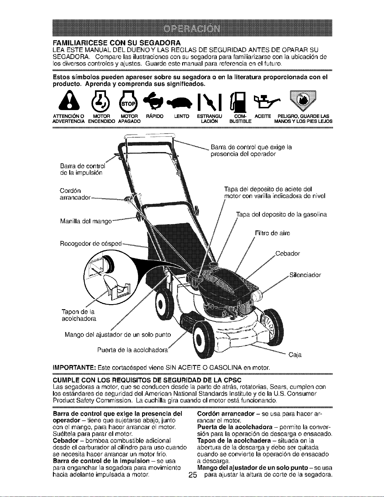
FAMILIARICESE CON SU SEGADORA
LEA ESTE MANUAL DEL DUENOY LAS REGLAS DE SEGURIDAD ANTES DE OPARAR SU
SEGADORA. Compare las ilustraciones con su segadora para familiarizarse con la ubicaci6n de
los diversos controles y ajustes. Guarde este manual para referencia en el futuro.
I=stos si'mbolos pueden apareser sobre su segadora o en la literatura proporcionada con el
produeto. Aprenda y eomprenda sus signifieados.
A'rrENCI6N O MOTOR MOTOR RAPIDO LENTO ESTRANGU COM- ACEITE PELIGRO, GUARDE LAS
ADVERTENCIA ENCENDIDO APAGADO LACI(SN BUSTIBLE MANOS Y LOS PIES LEJOS
Barra de control
de la impulsi6n
Barra de control que exige la
presencia del operador
Cord6n
Tapa del deposito de aciete del
motor con varilla indicadora de nivel
Manilla del mango
Recogedor de
deposito de la gasolina
Filtro de aire
Tapon de Ia
acolchadora
Mango del ajustador de un solo punto
Puerta de la acolchadora
caja
IMPORTANTE: Este cortac_sped viene SIN ACEITE O GASOLINA en motor.
CUMPLE CON LOS REQUISITOS DE SI=GURIDAD DE LA CPSC
Las segadoras a motor, que se conducen desde la parte de atr_s, rotatorias, Sears, cumpien con
los est_ndares de seguridad del American National Standards Institute y de la U.S. Consumer
Product Safety Commission. La cuchilla gira cuando el motor est_ funcionando.
Barra de control que exige la presencia del
operador - tiene que sujetarse abajo, junto
con el mango, para hacer arrancar el motor.
Su_lteia para parar el motor.
¢ebador - bombea combustible adicional
desde el carburador al cilindro para uso cuando
se necesita hacer arrancar un motor fdo.
Barra de control de la impulsion - se usa
para enganchar la segadora para movimiento
hacia adelante impulsada a motor.
Cordbn arrancador - se usa para hacer ar-
rancar el motor.
Puerta de la aeolchadora - permite la conver-
si6n para la operaci6n de descarga o ensacado.
Tapon de la aeolchadera - situada en Ia
abertura de la descarga y debe set quitada
cuando se convierte la operaci6n de ensacado
a descarga.
Mango del ajustador de un solo punto -se usa
25 para ajustar la aItura de corte de la segadora.
Laoperaci6ndecualquier
segadorapuedehacerque
saltenobjetosextraiiosdentrode
susoios,Ioquepuedeproducir
daSosgravesen_stos.Siempre
useanteojosdeseguddadoprotecci6npara
losojosrnientrasoperesusegadorao cuando
hagaajustesoreparaciones.Recomendamos
gafasounamascaradeseguridaddevisi6n
ampliadeseguridadusadasobrelasgalas.
COMO USAR SU SEGADORA
VELOCIDAD DEL MOTOR
La velocidad del motor se estableci6 en Ia fQ-
brica para un rendimiento 6primo. La velocidad
no se puede ajustar.
II_NTROL DE ZONA DEL MOTOR
PRECAUCION: Las regulaciones federales
exigen que se instale un control para el motor
en esta segadora para reducir a un rninimo el
riesgo de lesionarse debido aI contacto con la
cuchilla. Pot ning_n rnotivo trate de elirninar
la funci6n del control del operador. La cuchilla
gira cuando el motor est_ funcionando.
• Su segadora viene equipada con una barra
de controles que exigen la presencia del
operador, Io que requiere que el operador
est6 detrAs deI mango de la segadora para
hacerla arrancar y operada.
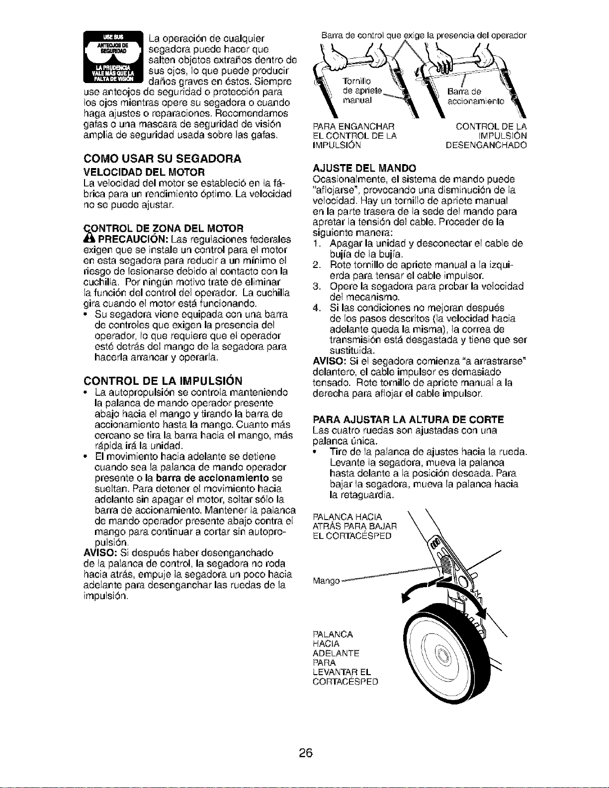
CONTROL DE LA IMPULSI(_N
• La autopropulsiSn se controta manteniendo
la palanca de mando operador presente
abajo hacia el mango y tirando la barra de
accionamiento basra la mango. Cuanto mAs
cercano se tira la barra hacia el mango, rn_s
r&pida it& la unidad.
• El movimiento hacia adelante se detiene
cuando sea la palanca de rnando operador
presente o la barra de aceionamiento se
sueItan. Para detener el rnovirniento hacia
adelante sin apagar el motor, soltar s61ola
barra de accionarniento. Mantener Ia palanca
de mando operador presente abajo contra el
mango para continuar a cortar sin autopro-
pulsi6n.
AVlSO: Si despu_s haber desenganchado
de la paIanca de control, la segadora no roda
hacia atr_s, empuje Ia segadora un poco hacia
adelante para desenganchar las ruedas de la
irnpulsi6n.
Barra de _ntrol que la presencia del operador
de Barra de
manual accionamiento
PARA ENGANCHAR
EL CONTROL DE LA
IMPULSION
CONTROL DE LA
iMPULSiON
DESENGANCHADO
AJUSTE DEL MANDO
Ocasionalmente, el sistema de mando puede
"afloiarse _,provocando una disminuci6n de Ia
velocidad. Hay un tornillo de apriete manual
en la parte trasera de la sede del rnando para
apretar la tensi6n del cable. Proceder de la
siguiente manera:
1. Apagar la unidad y desconectar el cable de
bujia de la bujfa.
2. Rote tomillo de apriete manual a la izqui-
erda para tensar el cable impulsor.
3. Opere la segadora para probar la velocidad
dei rnecanisrno.
4. Si las condiciones no rnejoran despu6s
de los pasos descritos (la velocidad hacia
adelante queda la misrna), la correa de
transrnisi6n est_ desgastada y tiene que set
sustituida.
AVISO: Si el segadora cornienza "a arrastrarse _
delantero, el cable impulsor es demasiado
tensado. Rote tornillo de apriete manual a la
derecha para afiojar el cable impulsor.
PARA AJUSTAR LA ALTURA DE CORTE
Las cuatro ruedas son ajustadas con una
palanca dnica.
• Tire de Ia palanca de ajustes hacia la rueda.
Levante Ia segadora, mueva Ia palanca
hasta delante a la posici6n deseada. Para
bajar Ia segadora, mueva la paIanca hacia
la retaguardia.
PALANCA HACIA
ATRAS PAP_A. BAJAR
EL CORTACESPED
Mangc
PALANCA
HACIA
ADELANTE
PARA
LEVANTAR EL
CORTACESPED
26
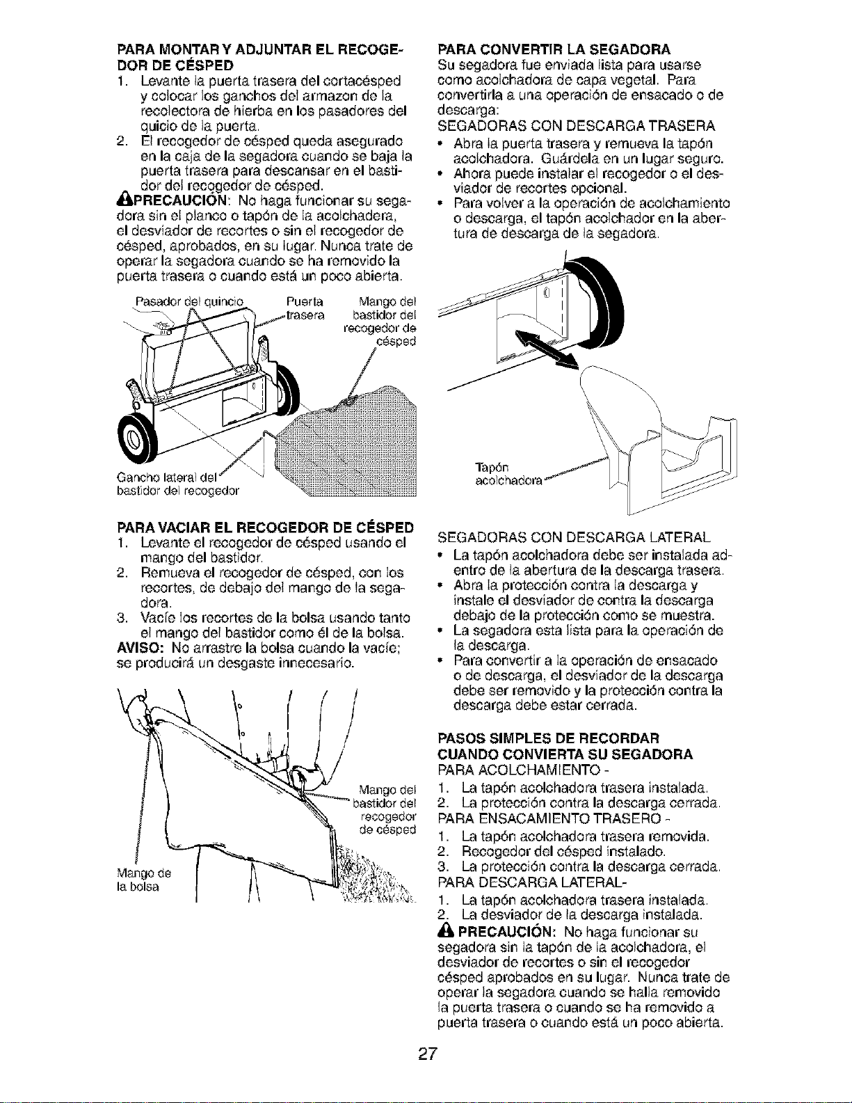
PARA MONTAR Y ADJUNTAR EL RECOGE-
DOR DE ClaSPED
1. Levante la puerta trasera del cortac6sped
y colocar los ganchos del arrnazon de la
reeolectora de hierba en los pasadores del
quicio de la puerta.
2. El recogedor de c_sped queda asegurado
en la ca]a de la segadora cuando se baja la
puerta trasera para descansar en el basti-
_dor del recogedor de c_sped.
PRECAUCION: No haga funcionar su sega-
dora sin el planco o tap6n de Ia acolchadera,
el desviador de recortes o sin el recogedor de
c6sped, aprobados, en su Iugar. Nunca trate de
operar la segadora cuando se ha rernovido la
puerta trasera o cuando est_ un poco abierta.
Pasador del aincio Puerta Mango del
_\ bastidor del
recogedor de
Gancho lateral del
bastidor del recogedor
PARA VACIAR EL RECOGEDOR DE CESPED
1. Levante el reeogedor de c_sped usando el
mango del bastidor.
2. Remueva el recogedor de c_sped, con los
recortes, de debajo del mango de Ia sega-
dora.
3. Vacle Ios recortes de la bolsa usando tanto
el mango del bastidor corno 51de la bolsa.
AVISO: No arrastre la bolsa cuando la vacie;
se produeir_ un desgaste innecesario.
/
Mango del
recogedor
de c_sped
Mango de
la bolsa
PARA CONVERTIR LA SEGADORA
Su segadora fue enviada lista para usarse
corno aeolchadora de capa vegetal. Para
convertirla a una operaci6n de ensacado o de
descarga:
SEGADORAS CON DESCARGA TRASERA
• Abra Ia puerta trasera y rernueva la tap6n
aeolchadora. Gu_rdela en un lugar seguro.
• Ahora puede instalar el recogedor o el des-
viador de recortes opcional.
• Para votver a la operaciSn de acolchamiento
o descarga, el tapSn acolchador en la abet-
tufa de descarga de la segadora.
\
Tap6n
SEGADORAS CON DESCARGA LATERAL
° La tap6n acolchadora debe set instalada ad-
entro de la abertura de la descarga trasera.
° Abra Ia proteeci6n eontra Ia descarga y
instale el desviador de contra la desearga
debajo de la proteceiSn eomo se rnuestra.
° La segadora esta lista para la operaciSn de
la descarga.
° Para eonvertir a Ia operaciSn de ensacado
o de descarga, el desviador de la desearga
debe set rernovido y la protecciSn contra la
descarga debe estar cerrada.
PASOS SIMPLES DE RECORDAR
CUANDO CONVIERTA SU SEGADORA
PAPA ACOLCHAMIENTO -
1. La tap6n aeolchadora trasera instalada.
2. La protecciSn contra la descarga cerrada.
PAPA ENSACAMIENTO TRASERO -
1. La tap6n acolehadora trasera rernovida.
2. Recogedor del e6sped instalado.
3. La protecciSn contra la descarga cerrada.
PAPA DESCARGA LATERAL-
1. La tap6n aeolehadora trasera instalada.
2. La desviador de la descarga instalada.
li_ PRI=CAUCl6N: No haga funcionar su
segadora sin Ia tapSn de Ia acolchadora, el
desviador de recortes o sin el recogedor
c6sped aprobados en su lugar. Nunca trate de
operar la segadora cuando se halla removido
la puerta trasera o cuando se ha rernovido a
puerta trasera o cuando est_ un poco abierta.
27
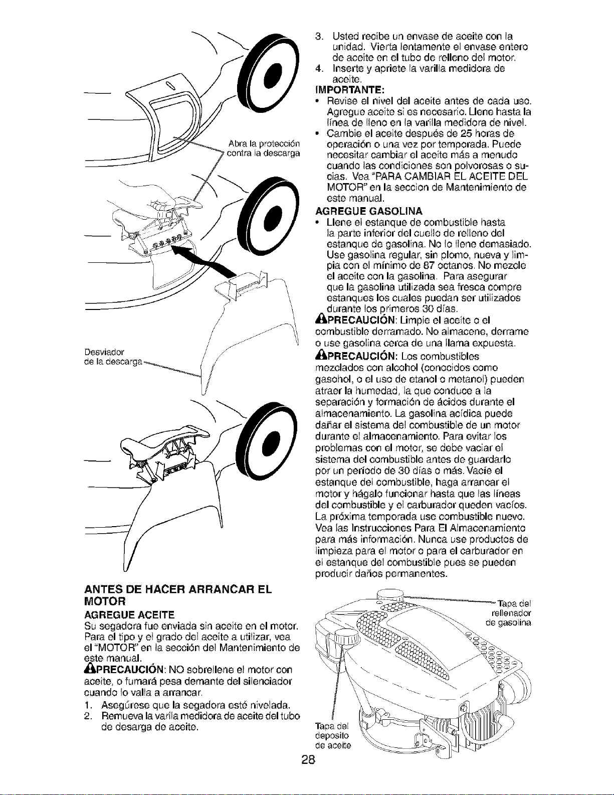
Abra la protecci6n
contra la descarga
J
3. Usted recibe un envase de aceite con la
unidad. Vierta lentarnente el envase enters
de aceite en el tube de relleno del motor.
4. Inserte y apriete la varilla medidora de
aceite.
IMPORTANTE:
• Revise el nivel del aceite antes de cada use.
Agregue aeeite si es necesario. Llene hasta la
li_neade liens en la varilla rnedidora de nivei.
• Carnbie el aceite despu6s de 25 horas de
operaci6n ouna vez per ternporada. Puede
necesitar cambiar el aceite m&s a rnenudo
cuando las condiciones son polvorosas o su-
cias. Vea "PARA CAMBIAR EL ACEITE DEL
MOTOR" en la seccion de Mantenirniento de
este manual.
AGREGUE GASOLINA
• Llene el estanque de combustible hasta
la parte inferior del cueilo de relleno del
estanque de gasolina. No Is Ilene demasiado.
Use gasolina regular, sin plomo, nueva y lim-
pia con el rninimo de 87 octanes. No mezcle
el aceite con la gasolina. Para asegurar
que la gasolina utilizada sea fresca compre
estanques los cuales puedan set utilizados
durante Ios p,rimeros 30 divas.
_kPRECAUCION: Lirnpie el aceite o el
combustible derramado. No almacene, derrarne
o use gasotina cerca de una llama expuesta.
_kPRECAUCI6N: Los combustibles
rnezclados con alcohol (conocidos como
gasohol, o el uso de etanol o rnetanol) pueden
atraer la humedad, la que conduce a Ia
separaci6n y forrnaci6n de _eidos durante el
atrnacenarniento. La gasolina acfdica puede
daiiar el sistema del combustible de un motor
durante eI alrnacenarniento. Para evitar los
problernas con el motor, se debe vaciar el
sisterna del combustible antes de guardarlo
per un periods de 30 divaso rn_s. Vacie el
estanque del combustible, haga arranear el
motor y h_galo funcionar hasta que las Iineas
del combustible y el carburador queden vacios.
La pr6xima temporada use combustible nuevo.
Vea las Instrucciones Para El Aimacenamiento
para rn_s irfformaci6n. Nunca use productos de
limpieza para el motor o para el carburador en
eI estanque del combustible pues se pueden
producir daSos permanentes.
ANTES DE HACER ARRANCAR EL
MOTOR
AGRI=GUI= ACI=ITE
Su segadora fue enviada sin aceite en el motor.
Para el tips y el grade del aceite a utilizar, yea
el "MOTOR" en la secei6n del Mantenirniento de
este manual.
ItIPRECAUCI(_N: NO sobrellene el motor solt
aceite, o furnar#_pesa dernar_te del sileneiador
cuando Io valla a arranear.
1. Asegdrese que la segadora est6 nivelada.
2. Remueva lavarila medidora de aceite del tubo
de desarga de aceite.
Tapa del
deposits
de aceite
rellenador
de gasolina
28
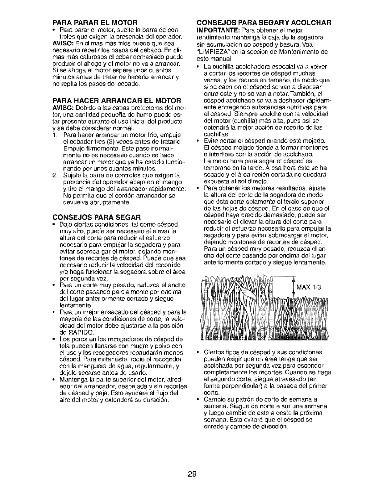
PARA PARAR EL MOTOR
• Para parar el motor, suelte la barra de con-
troles que exigen la preseneia del operador.
AVISO: En cl;rnas rn_s fries puede que sea
necesario repetir los pasos del cebado. En cli-
rnas rn_s calurosos el cebar demasiado puede
producir el ahogo y el motor no va a arranear.
Si se ahoga el motor espere unos cuantos
rninutos antes de tratar de hacedo arrancar y
no repita los pasos del cebado.
PARA HACER ARRANCAR EL MOTOR
AVISO: Debido alas capas protectoras del mo-
tor, una eantidad pequeSa de humo puede es-
tar presente durante el use inicial del producto
y se debe considerar normal.
1. Para haeer arrancar un motor frlo, empuje
el cebador tres (3) veces antes de tratado.
Ernpuje firmernente. Este paso norrnaI-
mente no es necesario cuando se hace
arrancar un motor que ya ha estado funcio-
nando per unos cuantos rninutos.
2. Sujete Ia barra de controles que exigen la
preseneia del operador abajo en el mango
y tire el mango del arrancador rapidarnente.
No permita que el cord6n arrancador se
devuelva abruptarnente.
CONSEJOS PARA SEGAR
• Bajo ciertas condiciones, tal come e6sped
muy alto, puede set necesario el elevar la
altura del corte para reducir el esfuerzo
necesario para empujar la segadora y para
evitar sobreeargar el motor, dejando rnon-
tones de recortes de c_sped. Puede que sea
necesario reducir la velocidad del recorrido
y/o haga funcionar la segadora sobre el _rea
per segunda vez.
• Para un corte rnuy pesado, reduzca el aneho
deI corte pasando parcialrnente per encima
deI Iugar anteriorrnente cortado y siegue
lentamente.
• Para un meier ensacado del c_sped y para la
mayoria de las condiciones de corte, Ia velo-
cidad deI motor debe ajustarse a la posici6n
de R_,PIDO.
• Los pores en los recogedores de c6sped de
tela pueden Ilenarse con rnugre y polvo con
el use y los recogedores recaudar_n menos
c6sped. Para evitar 6ste, rocie el recogedor
con la manguera de agua, regularmente, y
d6jelo secarse antes de usado.
• Mantenga la parte superior del motor, alred-
edor del arrancador, despejada y sin recortes
de c6sped y paja. Esto ayudar_ el fiujo del
aire del motor y extender& su duraci6n.
CONSEJOS PARA SEGAR Y ACOLCHAR
IMPORTANTE: Para obtener el meier
rendirniento rnantenga la caja de la segadora
sin acumulacion de cesped y basura. Vea
"LIMPIEZA _en la seccion de Mantenimento de
este rnanual.
• La cuchilla acolchadora especial va a velvet
a cortar los recortes de c_sped muchas
veces, y los reduce en tarnaSo, de rhode que
si se caen en el e6sped se van a dispesar
entre _ste y no se van a notar. Tarnbi6n, el
c_sped acolchado se va a deshaeer r_pidam-
ente entregando substaneias nutritivas para
el c6sped. Siernpre acolche con la velocidad
del motor (cuchilla) m_s alta, pues asf se
obtendr_ la meier acci6n de recorte de las
cuehillas.
• Evite eortar el c_sped euando este mojado.
El c_sped mojado tiende a forrnar montones
e interfiere con Ia acei6n de acolchado.
La rnejor hera para segar el c_sped es
temprano en la tarde. A esa hera 6ste se ha
seeado y el _rea reci6n cortada no quedar_
expuesta al sol directo.
• Para obtener los rnejores resultados, ajuste
la altura deI corte de la segadora de mode
que 6sta eorte solarnente el tereio superior
de las hojas de c_sped. En el ease de que el
c_sped haya crecido demasiado, puede set
necesario el elevar la altura deI corte para
reducir el esfuerzo necesario para empujar la
segadora y para evitar sobrecargar el motor,
dejando rnontones de recortes de c_sped.
Para un c_sped muy pesado, reduzea el an-
cho del eorte pasando per eneirna del Iugar
anteriormente cortado y siegue lentarnente.
MAX 1/3
• Ciertos tipos de c6sped y sus condiciones
pueden exigir que un _rea tenga que set
acolchada per segunda vez para esconder
completarnente los reeortes. Cuando se haga
el segundo corte, siegue atravesado (en
forma perpendicular) a la pasada del primer
corte.
• Carnbie su patron de corte de semana a
semana. Siegue de norte a sur una semana
y luego carnbie de este a oeste la pr6xirna
semana. Esto evitar& que el c6sped se
enrede y carnbie de direcci6n.
29
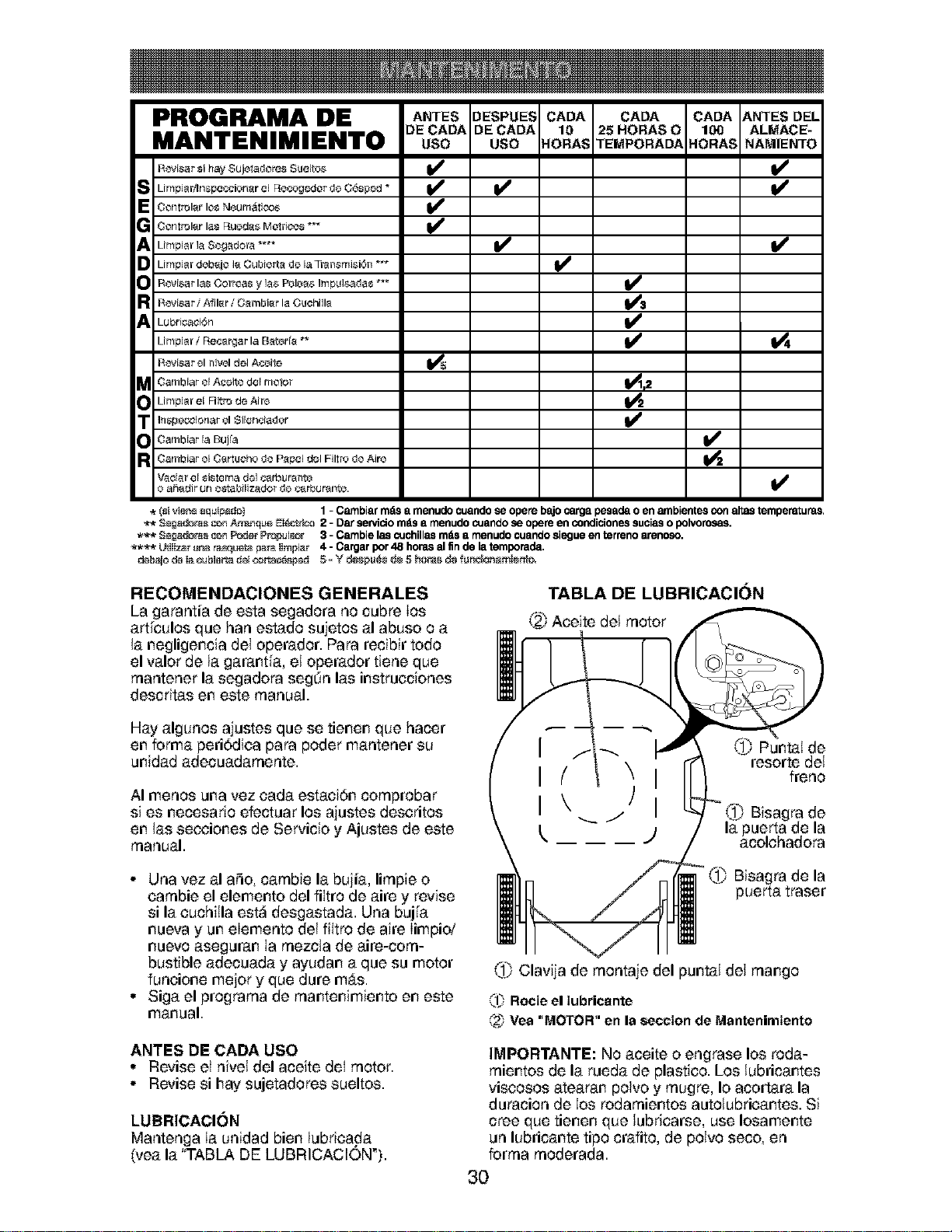
PROGRAMA DE A.TESOESPUESCAOA CAOA CAOAANTESOE,
)E CADA DE CADA 10 25 HORAS 0 100 ALMACE-
MANTENIMIENTO use use FLORAS TEMPORAD,_ HORAS NAMIENTO
RovEsar si hay Sujetadores SueEto_ _ _#
E_ Limpiadln_peccionarel Fiecogc<JordeG6sped *
Cof_rol_tr los Neurn_ioo_
Con_rol_tr la_ Fiuoda_ Mo_ric_s ***
Limpiar la Segadora .... _
_ impiar deb_jo I_ Cubierta de EaTran_mi_i6n ***
R_Esar las Correas y la_ Pole_ Impul_.ada_ ***
R_isar / Afiler / Gambler la Cuehille
Lubricaci(}n
Limpiar i Fiec_rgar la BatorI_ ** _
R_isar el nivol del Aceile
_ ambiar el Aceite del meier _2
Limpiar el RItro de Airo
_ nspeccionar el Silenciador
Oarnbiar la Bujfa
R Oambiar el C_rtucho do Papel del Filtro do Aire
Vaciar el sistema del cerbut_nto ,,J
o aS_tdir uf_ estabiEi_ador do _t rbur_tnte.
V
* _sivier_ equi_do) 1- Cambiarrndsa menudocuandose operebajocargapesadaoen ambientesconaltastemperaturas.
** Seg_r_ _ _q _e_I_i_ 2 - Darservido mdsa rnenudocuandose opereen condicionessuciaso polvorosas.
*** 3_£_z_s _ P_r Pr_pul_r 3 - Carnbielas c_Jchillasmasa menudocuandosiegueenterrenoarenoso.
**** _JIi_r _na r_ _ Iimpiar 4 - Cargarpor48 horasal finde latemporada.
RECOMENDACIONES GENERALES
La garantia de esta segadora no cubre Ios
artieulos que hart estado sujetos al abuse o a
la negligencia del operador. Para recibir todo
el valor de la garantla, el operador tiene que
rnantener la segadora segdn las instrucciones
descritas en este manual.
TABLA DE LUBRICACI(_N
@ Aceite del motor
Hay algunos ajustes que se tienen que hacer
en forma peri6dica para poder mantener su
unidad adecuadarnente.
AI menos una vez oada estaoidn cornprobar
si es necesario efectuar los ajustes descritos
en las secciones de Servicio y Ajustes de este
manual.
• Una vez al aSo, carnbie la bujia, lirnpie o
carnbie el elemento del filtro de aire y revise
si la euchilla est_ desgastada. Una bujla
nueva y un elemento del filtro de aire limpid
nuevo aseguran Ia rnezcla de aire-corn-
bustible adecuada y ayudan a que su motor
funeione mejor y que dure mAs.
• Siga el prograrna de rnar_ter_imiento en este
manual.
ANTES DE CADA USO
• Revise el nivel del aceite deI motor.
• Revise si hay sujetadores sueltos.
LUBRICACION
Mantenga Ia unidad bien lubrica.da
(yea la "TABLA DE LUBRICAClON%
I
I
I
k
Put,tat de
resorte del
freno
Bisagra de
la puerta de la
-') acolchadora
_ Bisagra de la
puerta traser
Clavija de rnontaje del puntal del mango
_'lbRetie el Iubricante
_'2_ Vea "MOTOR" en la section de Mantenimiento
IMPORTANTE: No aceite o engrase los roda-
rnientos de la rueda de plastico. Los lubricantes
viseosos atearan poivo y rnugre, Io acortara la
duracion de Ios rodarnientos autolubricantes. Si
cree que tienen que lubricarse, use Iosamente
un lubricante tipo crafito, de polvo seco, en
forrna rnoderada.
3O
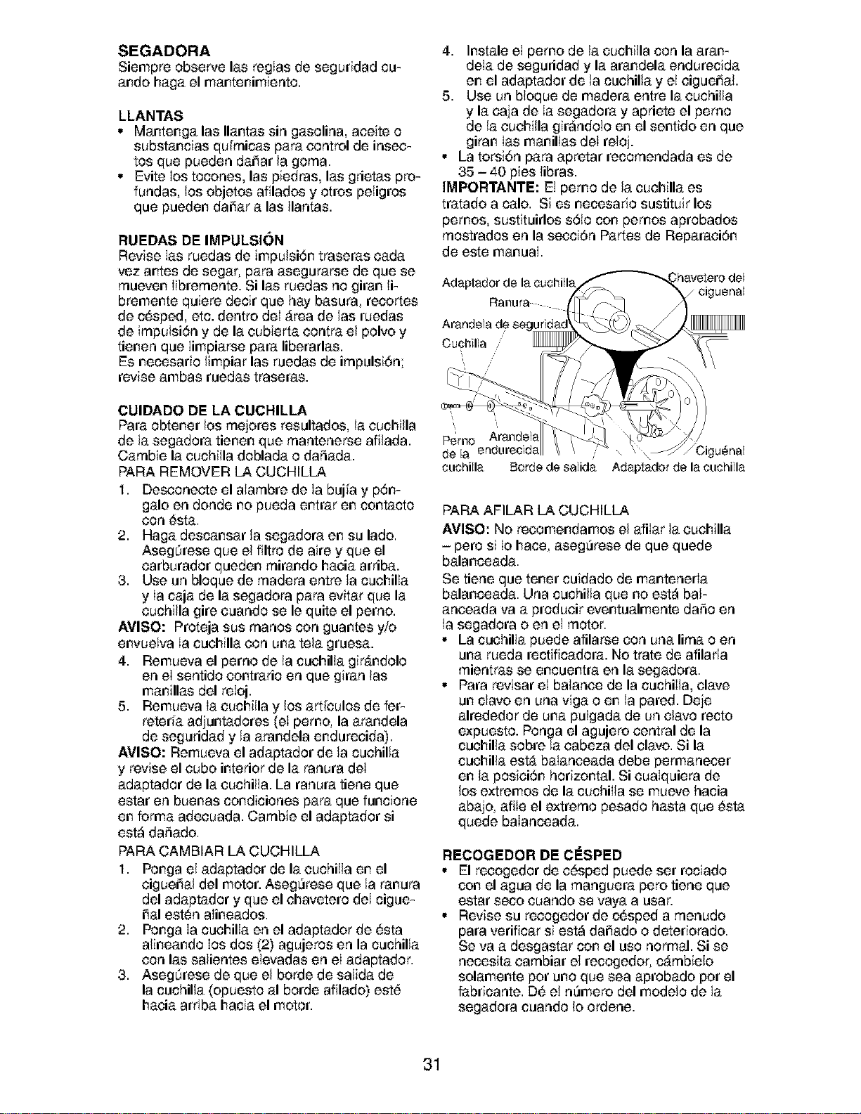
SEGADORA
Siempre observe las regIas de seguridad cu-
ando haga el mantenimiento.
LLANTAS
• Mantenga las Ilantas sin gasolina, aceite o
substancias qulmnicas para control de insec-
tos que pueden daiiar la gorna.
• Evite Ios tocones, las piedras, las grietas pro-
fundas, los objetos afilados y otros peligros
que pueden daiiar alas Ilantas.
RUEDAS DE IMPULSION
Revise Ias ruedas de impulsi6n traseras cada
vez antes de segar, para asegurarse de que se
rnueven Iibrernente. Si las ruedas no giran li-
bremente quiere decir que hay basura, recortes
de c_sped, etc. dentro deI _rea de las ruedas
de irnpulsi6n y de la cubierta contra el polvo y
tienen que Iimpiarse para liberarlas.
Es necesario limpiar las ruedas de irnpulsi6n;
revise ambas ruedas traseras.
CUIDADO DE LA CUCHILLA
Para obtener los rnejores resultados, la cuchilla
de la segadora tienen que rnantenerse afilada.
Carnbie la cuchilla doblada o daSada.
PARA REMOVER LA CUCHILLA
1. Desconecte el alarnbre de la bujla y p6m
galo en donde no pueda entrar en contacto
con 6sta.
2. Haga descansar la segadora en su lado.
Asegdrese que el filtro de aire y que el
carburador queden rnirando hacia arriba.
3. Use un bloque de rnadera entre la cuchilIa
y Ia caja de la segadora para evitar que la
cuchilla gire cuando se le quite el perno.
AVISO: Proteja sus rnanos con guantes y/o
envueIva Ia cuchilla con una tela gruesa.
4. Remueva el perno de la cuchilla gir_ndolo
en el sentido contrario en que giran las
manillas del reloj.
5. Remueva Ia cuchilla y los artlculos de fer-
reterla adjuntadores (el pemo, la arandela
de seguridad y la arandela endurecida).
AVlSO: Remueva el adaptador de la cuchilla
y revise el cubo interior de la ranura del
adaptador de la cuchilla. La ranura tiene que
estar en buenas condiciones para que funcione
en forma adecuada. Carnbie el adaptador si
est_ daSado.
PARA CAMBIAR LA CUCHILLA
1. Ponga el adaptador de la cuchilla en el
cigueiial del motor. Aseg_rese que la ranura
del adaptador y que el chavetero del cigue-
iial est_n aIineados.
2. Ponga Ia cuchilla en el adaptador de _sta
alineando Ios dos (2) agujeros en la cuchilla
con las salientes elevadas en el adaptador.
3. Asegdrese de que el borde de salida de
la cuchilla (opuesto al borde afilado) est6
hacia arriba hacia el motor.
4. Instale el pemo de la cuchiIla con la aran-
dela de seguridad y la arandela endurecida
en el adaptador de la cuchilla y el cigueiiat.
5. Use un bloque de madera entre la cuchilla
y la caia de Ia segadora y apriete el pemo
de la cuchilla gir_ndolo en el sentido en que
giran Ias manillas del reloj.
• La torsi6n para apretar recornendada es de
35 - 40 pies libras.
IMPORTANTE: El pemo de la cuchilla es
tratado a calo. Si es necesario sustituir los
pemos, sustituirlos s61o con pemos aprobados
rnostrados en la secci6n Partes de Reparaci6n
de este manuaI.
Cuchilla ,'
/
/ ciguenal
\
P 'rn Arandela.
e O
de la endurec_da \ u_nal
cuchilla Borde de salida Adaptador de la cuchilla
PAPA AFILAR LA CUCHILLA
AVISO: No recomendamos el afilar la cuchilla
- pero si Io hace, aseg_rese de que quede
balanceada.
Se tiene que tener cuidado de mantenerla
balanceada. Una cuchilla que no est_ baF
anceada va a producir eventualmente daSo en
la segadora o en el motor.
• La cuchilla puede afilarse con una lima o en
una rueda rectificadora. No trate de afilarla
rnientras se encuentra en la segadora.
• Para revisar eI balance de la cuchiIIa, clave
un clavo en una viga o en la pared. Deje
alrededor de una pulgada de un clavo recto
expuesto. Ponga el agujero central de la
cuchilla sobre la cabeza del clavo. Si la
cuchilla est_ baianceada debe permanecer
en la posici6n horizontal. Si cuaIquiera de
los extremos de la cuchiIla se mueve hacia
abajo, afile el extrerno pesado hasta que 6sta
quede baIanceada.
RECOGEDOR DE CESPED
• El recogedor de c6sped puede set rociado
con el agua de la rnanguera pero tiene que
estar seco cuando se vaya a usar.
• Revise su recogedor de c6sped a rnenudo
para verificar si est_ dai_ado o deteriorado.
Se va a desgastar con el uso normal. Si se
necesita carnbiar el recogedor, cArnbielo
solamente pot uric que sea aprobado pot el
fabricante. D6 el n_mero del modelo de la
segadora cuando Io ordene.
31
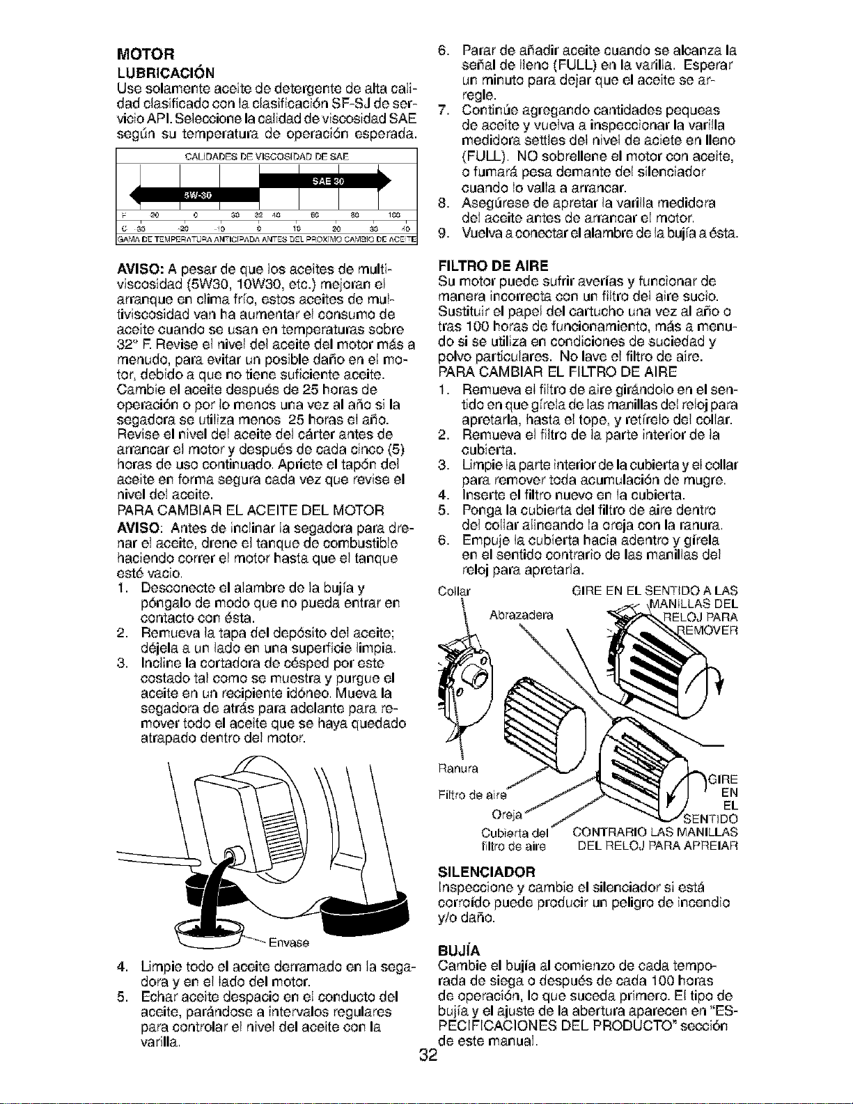
MOTOR
LUBRICACION
Use solamente aceite de detergente de alta caIi-
dad clasificado con Ia clasificaci6n SF-SJ de ser-
vioio API. Seleccione la calidad de viscosidad SAE
segdn su ternperatura de operaci6n esperada.
CAUDADES DE VISCOSIDAD DE SAE
AVISO: A pesar de que los aceites de rnulti-
viscosidad (5W30, 10W30, etc.) rnejoran el
arranque en clima trio, estos aceites de rnuF
tiviscosidad van ha aurnentar el consume de
aceite cuando se usan en ternperaturas sobre
32" R Revise el nivel del aceite del motor m&s a
rnenudo, para evitar un posible daiio en el mo-
tor, debido a que no tiene suficiente aceite.
Carnbie el aceite despu6s de 25 betas de
operaei6n o per Io menos una vez al aSo si la
segadora se utiliza rnenos 25 betas el aiio.
Revise el nivel del aceite del c_rter antes de
arrancar el motor y despu6s de cada cinco (5)
horas de use continuado. Apriete el tap6n del
aceite en forma segura cada vez que revise el
nivel del aceite.
PARA CAMBIAR EL ACEITE DEL MOTOR
AVlSO: Antes de inclinar Ia segadora para dre-
nat el aceite, drene el tanque de combustible
haciendo cotter el motor hasta que el tanque
est6 vacio.
1. Desconecte el alarnbre de la bujla y
p6ngalo de mode que no pueda entrar en
contacto con 6sta.
2. Remueva la tapa del dep6sito del aceite;
d6jela a un lade en una superficie limpia.
3. Incline la cortadora de c6sped per este
costado tal corno se muestra y purgue el
aceite en un recipiente id6neo. Mueva la
segadora de atr&s para adelante para re-
mover todo el aceite que se haya quedado
atrapado dentro del motor.
6. Parar de aiiadir aceite cuando se alcanza la
seiial de Ileno (FULL) en la varilIa. Esperar
un rninuto para dejar que el aceite se ar-
regle.
7. ContinUe agregando cantidades pequeas
de aceite y vuelva a inspeccionar la varilla
medidora settles del nivel de aciete en Ileno
(FULL). NO sobrellene el motor con aceite,
o fumar_, pesa demante del silenciador
cuando Io valla a arrancar.
8. Aseg_rese de apretar la varilla rnedidora
del aceite antes de arrancar el motor.
9. Vuelva a conectar el alarnbre de la bujla a _sta.
FILTRO DE AIRE
Su motor puede sufrir averias y funcionar de
rnanera incorrecta con un filtro del aire sucio.
Sustituir el papel del cartucho una vez al aiio o
tras 100 betas de funeionarniento, rn_s a menu-
do si se utiliza en condiciones de suciedad y
polvo particulates. No lave el filtro de aire.
PAPA CAMBIAR EL FILTRO DE AIRE
1. Remueva el filtro de aire gir_ndoto en el sen-
tide en que gi_relade Ias rnanillas del reloj para
apretarla, hasta el tope, y ret[relo del collar.
2. Remueva el filtro de la parte interior de la
cubierta.
3. Lirnpie Ia parte interior de la cubierta y el collar
para remover toda aeumulaci6n de rnugre.
4. Inserte el filtro nuevo en Ia cubierta.
5. Ponga la cubierta del filtro de aire dentro
del collar alineando Ia oreja con la ranura.
6. Empuje Ia eubierta hacia adentro y girela
en el sentido contrario de las manillas del
reloj para apretarla.
Colla.r GIRE EN EL SENTIDO ALAS
DEL
Abrazadera RELOJ PAPA
4,
5.
Ranura
Filtro de aire
}IRE
EN
EL
Cubierta del CONTRARIO LAS MANILLAS
tiltro de aire DEL RELOJ PARA APREIAR
SILENCIADOR
Inspeccione y carnbie el silenciador si est_
corroido puede producir un peligro de incendio
y/o daSo.
Urnpie todo el aceite derramado en la sega-
dora yen el lade del motor.
Echar aceite despacio en el condueto del
aceite, par_ndose a intervalos regulates
para controlar el nivel del aceite con la
varilla.
BUJfA
Carnbie el bujia al comienzo de cada ternpo-
rada de siega o despu6s de cada 100 betas
de operaci6n, Io que sueeda prirnero. El tipo de
bujla y el ajuste de la abertura aparecen en "ES-
PECIFICACIONES DEL PRODUCTO _secci6n
de este manuaI.
32
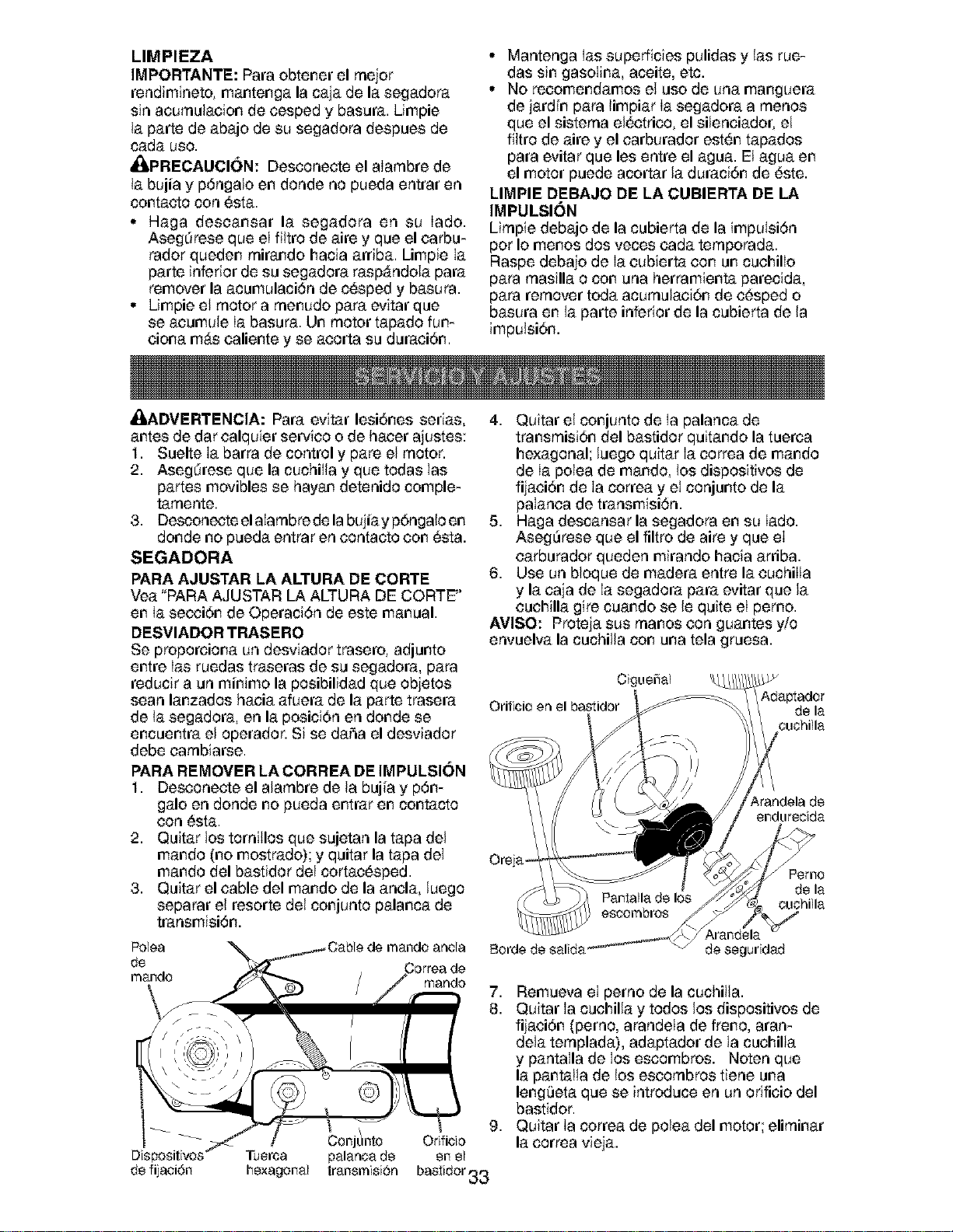
LIMPIEZA
IMPORTANTE: Para obtener el mejor
rendimineto, mantenga la caja de la segadora
sin acumulacion de cesped y basura. Umpie
la parte de abajo de su segadora despues de
cada use.
_PRECAUCl6N: Desconecte el aIambre de
la bujia y p6ngalo en deride no pueda entrar en
contaeto con 6sta.
° Haga descansar la segadora en su Iado.
Asegdrese que el filtro de aire y que el earbu-
fader queden mirando hacia arriba. Limpie Ia
parte inferior de su segadora raspAndola para
remover la acumulaci6n de c6sped y basura.
° Limpie el motor a menudo para evitar que
se acumule Ia basura. Un motor tapado fun-
ciona m_s caliente y se acorta su duraci6n.
• Mantenga Ias superficies pulidas y las rue-
das sin gasoiina, aceite, etc.
• No recomendamos el use de una manguera
de jardln para limpiar Ia segadora a menos
que el sistema ei_etrieo, el silenciador, el
fikro de aire y el carburador est_n tapados
para evitar que les entre el agua. El agua en
el motor puede acortar la duraci6n de 6ste.
LIMPIE DEBAJO DE LA CUBIERTA DE LA
IMPULSION
Limpie debajo de la cubierta de la impuisi6n
per Io menos dos veces cada temporada.
Raspe debajo de Ia cubierta con un cuehillo
para masilla o con una herramienta parecida,
para remover toda acumulaci6n de e6sped o
basura en la parte inferior de la cubierta de la
impuisi6n.
_.DVERTENCIA: Para evitar lesi6nes serias,
antes de dar calquier service o de hacer ajustes:
1. Suelte Ia barra de control y pare el motor.
2. Asegdrese que la cuchilla y que todas las
partes movibles se hayan detenido comple-
tamente.
3. Desconecte el aIambre de la bujiay p6ngalo en
deride no pueda entrar en contacto con _sta.
SEGADORA
PARA AJUSTAR LA ALTURA DE CORTE
Vea "PARA AJUSTAR LA ALTURA DE CORTE"
en Ia secci6n de Operaci6n de este manual.
DESVIADOR TRASERO
Se proporciona un desviador trasero, adjunto
entre Ias ruedas traseras de su segadora, para
reducir a un minimo la posibilidad que objetos
sean lanzados haeia afuera de la parte trasera
de la segadora, en la posici6n en deride se
encuentra el operador. Si se daSa el desviador
debe cambiarse.
PARA REMOVER LA CORREA DE IMPULSI()N
1. Desconecte el alambre de la buj_a y p6n-
gale en deride no pueda entrar en contacto
con 6sta.
2. Quitar los torniilos que sujetan la tapa del
mando (no mostrado); y quitar la tapa del
mando del bastidor del cortac6sped.
3. Quitar el cable del mando de la ancla, luego
separar el resorte del conjunto palanca de
transmisi6n.
4. Quitar el conjunto de Ia palanca de
transmisi6n del bastidor quitando la tuerca
hexagonal; luego quitar Ia eorrea de mando
de Ia polea de mando, los dispositivos de
fijaei6n de Ia correa y el conjunto de la
palanca de transmisi6n.
5. Haga descansar la segadora en su Iado.
Aseg_rese que el filtro de aire y que el
carburador queden mirando hacia arriba.
6. Use un bloque de madera entre la euchilla
y la caja de la segadora para evitar que la
cuchilla gire cuando se le quite el perno.
AVISO: Proteja sus manes con guantes y/o
envuelva la cuchilla con una tela gruesa.
Orilicioen
Adaptador
de la
ouohilla
_,randela de
endurecida
Oreja
Pemo
de la
cuchilla
Polea
de
mando
de fijaci6n
mando
7,
8.
de seguridad
,
Conjt_nto Orificio
Tuerca palanca de en el
hexagonal transmisi6n bastidor33
Remueva el perno de la cuchilla.
Quitar Ia cuehilla y todos los dispositivos de
fijaei6n (perno, arandela de freno, aran-
dela templada), adaptador de la cuehilla
y pantalla de los escombros. Noten que
la pant.alia de los escombros tiene una
leng_ieta que se introduce en un orificio del
bastidor.
Quitar Ia correa de polea del motor; eliminar
la correa vieja.
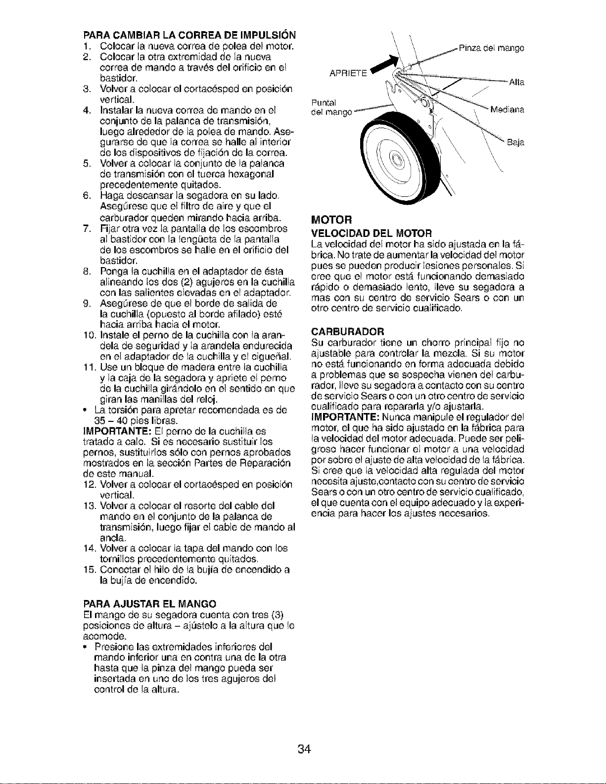
PARA CAMBIAR LA CORRI=A DE IMPULSION
1. Colocar Ia nueva correa de polea del motor.
2. Colocar Ia otra extremidad de la nueva
correa de rnando a trav6s del orificio en el
bastidor.
3. Velvet a colocar el cortac6sped en posici6n
vertical.
4. Instalar la nueva correa de mando en el
conjunto de la palanca de transrnisi6n,
luego alrededor de la poiea de mando. Ase-
gurarse de que la correa se halle al interior
de los dispositivos de fijaci6n de la correa.
5. Velvet a eolocar la eonjunto de la paIanca
de transmisiSn con el tuerca hexagonal
precedenternente quitados.
6. Haga descansar la segadora en su lade.
Asegdrese que el filtro de aire y que el
carburador queden rnirando haeia arriba.
7. Fijar otra vez Ia pantaIla de Ios escombros
aI bastidor con la Ieng_ieta de la pantalla
de los escombros se halle en el orificio del
bastidor.
8. Ponga Ia cuchilIa en el adaptador de 6sta
alineando Ios dos (2) agujeros en la cuchilla
con las salientes eievadas en el adaptador.
9. Asegdrese de que el borde de salida de
la cuchilla (opuesto al borde afilado) est6
haoia ardba hacia el motor.
10. Instale el perno de la cuchilla con la aran-
dela de seguridad y Ia arandela endureeida
en el adaptador de Ia cuehilla y eI cigueSal.
11. Use un bloque de rnadera entre Ia cuehilIa
y la caja de la segadora y apriete el pemo
de la cuchiIia gir&ndolo en el sentido en que
giran las rnanillas del reloj.
• La torsi6n para apretar recomendada es de
35 - 40 pies libras.
IMPORTANTE: El perno de la cuchilla es
tratado a eaIo. Si es neeesario sustituir Ios
pernos, sustituidos s61ocon pernos aprobados
rnostrados en Ia secci6n Partes de Reparaci6n
de este manual.
12. Velvet a colocar el cortac6sped en posiei6n
vertical.
13. Velvet a colocar el resorte del cable del
mando en el conjunto de la palanca de
transmisi6n, luego fijar el cable de rnando al
anela.
14. Velvet a coiocar Ia tapa del mando con los
torniIlos preeedentemente quitados.
15. Conectar el hiIo de Ia bujia de encendido a
la bujia de encendido.
PARA AJUSTAR EL MANGO
El mango de su segadora cuenta con tres (3)
posieiones de altura - ajOstelo a la altura que le
aeornode.
° Presione las extrernidades inferiores del
mando inferior una en contra una de la otra
hasta que Ia pinza dei mango pueda set
insertada en uno de los tres agujeros del
control de la altura.
Puntal
del
\
\
MOTOR
VI=LOCIDAD DI=L MOTOR
La velocidad del motor ha side ajustada en la f_-
brica. No trate de aumentar la velocidad del motor
pues se pueden producir Iesiones personates. Si
cree que el motor est_ funcionando dernasiado
r_pido o dernasiado lento, Ileve su segadora a
rnas con su centre de servicio Sears o con un
otto centre de servicio cualificado.
CARBURADOR
Su carburador tiene un chorro principal fijo no
ajustable para controlar la mezela. Si su motor
no est_ funcionando en forma adecuada debido
a problemas que se sospecha vienen del carbu-
fader, Ileve su segadora a contacto con su centre
de servicio Sears o con un otto centre de servicio
cualificado para repararla y/o ajustarla.
IMPORTANTE: Nunea rnanipule el regulador del
motor, el que ha side ajustado en la f_brica para
la velocidad del motor adeeuada. Puede set peli-
groso hacer funcionar el motor a una velocidad
per sobre el ajuste de alta velocidad de la fabric&
Si cree que Ia velocidad alta regulada del motor
necesita ajuste,eontacto con su centre de servieio
Sears o con un otto centre de servicio cuaIificado,
el que cuenta con el equipo adecuado y la experi-
encia para hacer los ajustes necesarios.
34
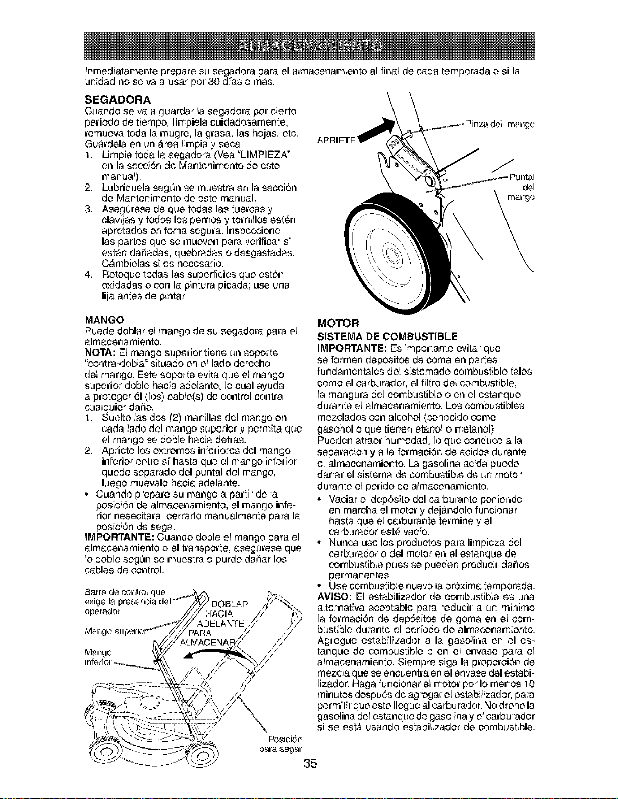
Inmediatamente prepare su segadora para el aIrnacenamiento al final de cada temporada o si la
unidad no se va a usar pot 30 dlas o rn_s.
SEGADORA
Cuando se va a guardar la segadora pot cierto
periodo de tiernpo, limpiela cuidadosamente,
rernueva toda Ia mugre, la grasa, las hojas, etc.
Gu_rdela en un _rea Iimpia y seca.
1. Lirnpie toda la segadora (Vea"LIMPIEZA _
en la secci6n de Mantenimento de este
manual).
2. Lubriquela segdn se rnuestra en la seccidn
de Mantenimento de este manual.
3. Asegdrese de que todas las tuercas y
clavijas y todos los pemos y tomillos est_n
apretados en forna segura. Inspeccione
las partes que se mueven para verificar si
estAn dai_adas, quebradas o desgastadas.
C_mbielas si es necesario.
4. Retoque todas Ias superficies que est6n
oxidadas o con la pintura picada; use una
lija antes de pintar.
MANGO
Puede doblar el mango de su segadora para el
almacenarniento.
NOTA: El mango superior tiene un soporte
"contra-dobla" situado en el lado derecho
del mango. Este soporte evita que el mango
superior doble hacia adelante, Io cual ayuda
a proteger 51(los) cable(s) de control contra
cuaIquier daSo.
1. Suelte las dos (2) rnanillas del mango en
cada lado del mango superior y permita que
el mango se doble hacia detras.
2. Apriete los extremos inferiores del mango
inferior entre sl_hasta que el mango inferior
quede separado del puntal del mango,
luego rnu_valo hacia adelante.
• Cuando prepare su mango a partir de Ia
posici6n de almacenamiento, el mango infe-
rior nesecitara cerrado rnanualrnente para la
posici6n de sega.
IMPORTANTE: Cuando doble el mango para el
almacenarniento o el transporte, aseg_rese que
Io doble seg_n se muestra o purde daSar los
cables de control.
Ba:rrade control que
operador
MOTOR
SISTEMA DE COMBUSTIBLE
IMPORTANTE: Es irnportante evitar que
se formen depositos de coma en partes
fundamentales del sisternade combustible tales
corno el carburador, el fikro del combustible,
la rnangura deI combustible o en el estanque
durante el alrnacenarniento. Los combustibles
rnezclados con alcohol (conocido come
gasohol o que tienen etanol o metanol)
Pueden atraer humedad, to que conduce a la
separacion y a la forrnaci6n de acidos durante
el alrnacenarniento. La gasolina acida puede
danar el sistema de combustible de un motor
durante el perido de almacenamiento.
• Vaciar el depdsito del carburante poniendo
en rnarcha el motor y dej_ndolo funcionar
hasta que el carburante terrnine y el
carburador est6 vacio.
• Nunca use los productos para lirnpieza del
carburador o del motor en el estanque de
combustible pues se pueden producir daiios
perrnanentes.
• Use combustible nuevo Ia pr_txima ternporada.
AVISO: El estabilizador de combustible es una
attemativa aceptable para reducir a un rninirno
la forrnaci6n de dep6sitos de gorna en el com-
bustible durante el perfodo de almacenamiento.
Agregue estabilizador a la gasolina en el es-
tanque de combustible o en el envase para el
;// atrnacenarniento. Siernpre siga la proporcidn de
rnezcla que se encuentra en el envase del estabi-
lizador. Haga funcionar el motor pot Io menos 10
rninutos despu6s de agregar el estabilizador, para
perrnitir que este Ilegue al carburador. No drene la
gasolina del estanque de gasolina y el carburador
si se est_ usando estabilizador de combustible.
Posici6n
para segar
35
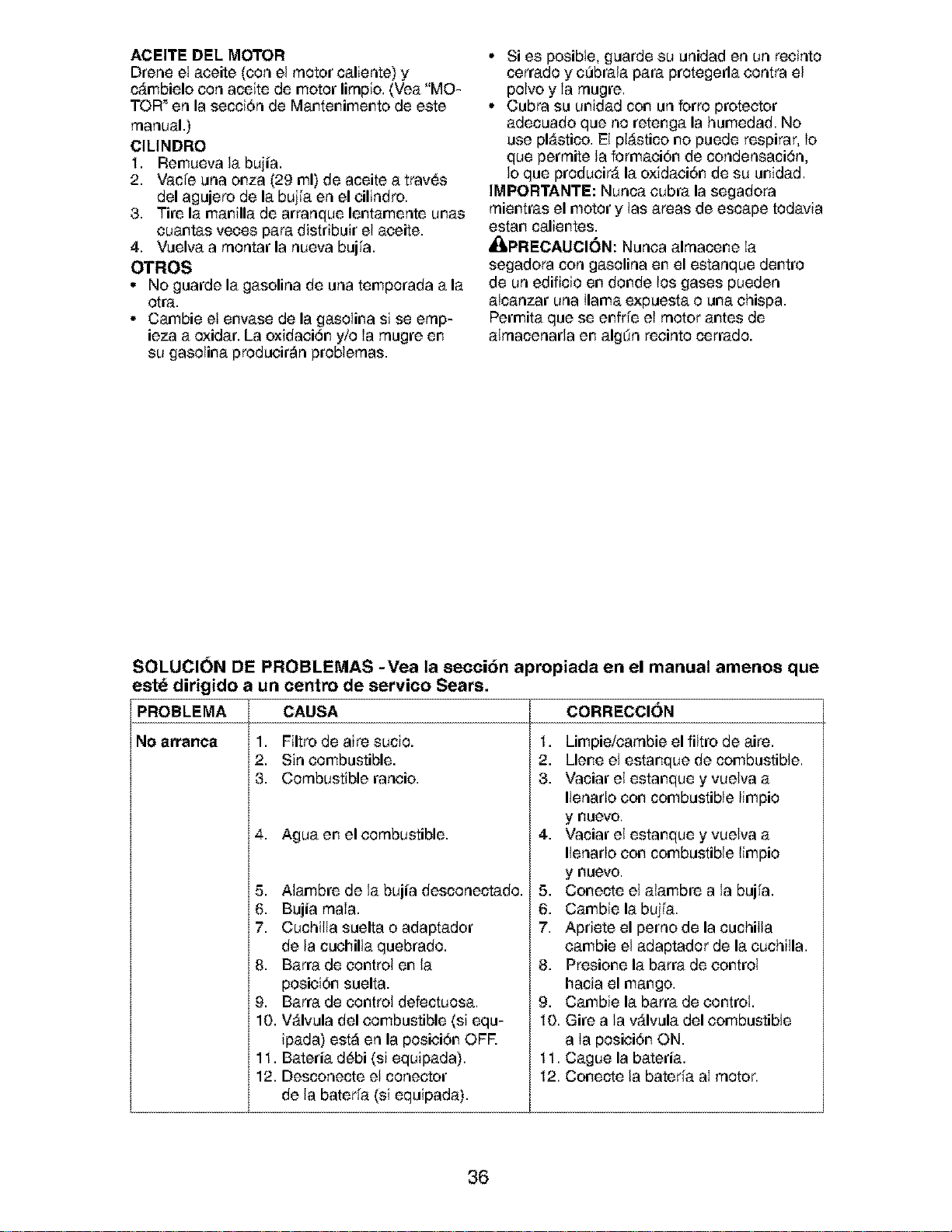
ACEITE DI=L MOTOR
Drene el aceite (con el motor caliente) y
c_mbielo con aceite de motor lirnpio. (Vea "MO-
TOR _en la secci6n de Mantenimento de este
manual.)
CILINDRO
1. Remueva la bujia.
2. Vacie una onza (29 ml) de aceite a trav6s
del agujero de la bujla en el cilindro.
3. Tire la manilla de arranque lentamente unas
cuantas veces para distribuir el aceite.
4. Vuelva a rnontar la nueva bujla.
OTROS
• No guarde la gasolina de una temporada a la
otra.
• Cambie el envase de la gasoiina si se ernp-
ieza a oxidar. La oxidaci6n y/o Ia rnugre en
su gasoiina producir_n probiernas.
• Si es posible, guarde su unidad en un recinto
cerrado y c_brala para protegerla contra el
polvo y Ia rnugre.
° Cubra su unidad con un forro protector
adecuado que no retenga la humedad. No
use pl_stico. El pl_stico no puede respirar, Io
que perrnite la formaci6n de condensaci6n,
Io que producir_ la oxidaci6n de su unidad.
IMPORTANTE: Nunca cubra la segadora
rnientras el motor y las areas de escape todavia
estan calientes.
_PRECAUOION: Nunca alrnacene Ia
segadora con gasolina en el estanque dentro
de un edificio en donde los gases pueden
atcanzar una llama expuesta o una chispa.
Permita que se enfrle el motor antes de
alrnacenarla en algdn recinto cerrado.
SOLUCION DE PROBLEMAS -Yea la section apropiada en el manual amenos que
este dirigido a un centro de servico Sears.
PROBLEMA CAUSA
No arranca 1. Filtro de aire sucio.
2. Sin combustible.
3. Combustible rancio.
4. Agua en el combustible.
5. Alambre de la bujia desconectado.
6. Bujia rnaIa.
7. Cuchilla suelta o adaptador
de la cuchilla quebrado.
8. Barra de control en la
posici6n suelta.
9. Barra de control defectuosa.
10. V_lvula del combustible (si equ-
ipada) est_ en la posici6n OFR
11. Bateria d6bi (si equipada).
12. Desconecte el conector
de la baterla (si equipada).
CORRECCI()N
1. Limpie/carnbie el filtro de aire.
2. Llene el estanque de combustible.
3. Vaciar el estanque y vueiva a
llenarIo con combustible limpio
y nuevo.
4. Vaciar el estanque y vueiva a
llenarIo con combustible limpio
y nuevo.
5. Conecte el aiambre a la buila.
6. Cambie la bujla.
7. Apriete el perno de la cuchiIla
cambie el adaptador de la cuchilla.
8. Presione la barra de control
hacia el mango.
9. Cambie la barra de control.
10. Gire a la vAIvula del combustible
a Ia posici6n ON.
11. Cague la bateria.
12. Conecte la bateria aI motor.
36
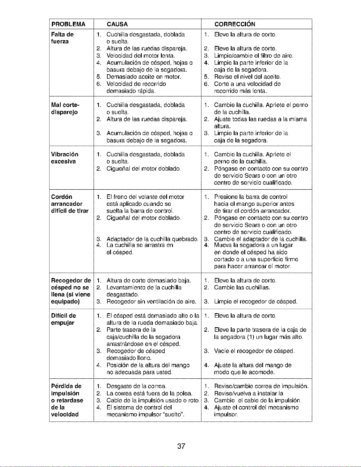
PROBLEMA
Falta de
fuerza
Mal corte-
disparejo
Vibracibn
excesiva
i
Cord6n
arrancador
diffcil de tirar
Recogedor de
cesped no se
Ilena (si viene
equipado)
Dificil de
empujar
Perdida de
impulsibn
o retardase
de la
velocidad
CAUSA
1. Cuchilla desgastada, doblada
o suelta.
2. Altura de las ruedas dispareja.
3. Velocidad del motor lenta.
4. Acumulaci6n de c_sped, hojas o
basura debajo de Ia segadora.
5. Dernasiado aceite en motor.
6. Velocidad de reeorrido
demasiado r_pida.
1. Cuchilla desgastada, doblada
o suelta.
2. Altura de las ruedas dispareja.
3. Acumulaci6n de c_sped, hojas o
basura debajo de Ia segadora.
1. Cuchilla desgastada, doblada
o suelta.
2. Cigueiiat del motor doblado.
1. El freno del volante del motor
est_ aplicado cuando se
suelta la barra de control.
2. Cigueiial del motor doblado.
3. Adaptador de la cuchilla quebrado.
4. La cuchilla se arrastra en
el c6sped.
1. Aitura de corte dernasiado baja.
2. Levantamiento de la euehilla
desgastado.
3. Recogedorsin ventilaci6n de aire.
1. El c6sped estA demasiado alto o la
altura de la rueda demasiado baja.
2. Parte trasera de Ia
cajdeuchilla de la segadora
arrastr&ndose en el c6sped.
3. Recogedor de e6sped
demasiado Ileno.
4. Posiei6n de la altura deI mango
no adecuada para usted.
1. Desgaste de la correa.
2. La correa est_ fuera de la polea.
3. Cable de la irnpulsi6n usado o rote.
4. El sistema de control del
rnecanisrno irnpulsor "sueIto".
1,
CORRECCION
Eleve la altura de corte.
2. Eleve la altura de corte.
3. Limpie/carnbie el filtro de aire.
4. Limpie la parte inferior de la
caja de la segadora.
5. Revise el nivel del aeeite.
6. Corte a una velocidad de
recorrido rn_s lenta.
1. Cambie la cuchilla. Apriete el pemo
de Ia cuchilla.
2. Ajuste todas las ruedas a la misma
altura.
3. Limpie la parte inferior de la
eaja de la segadora.
1. Cambie la cuchilla. Apriete el
perno de la cuehilla.
2. P6ngase en eontacto con su centre
de servicio Sears o con un otto
centre de servicio cualificado.
1. Presione la barra de control
hacia el mango superior antes
de tirar el eord6n arrancador.
2. P6ngase en eontacto con su centre
de servicio Sears o con un otto
centre de servicio cualificado.
3. Cambie el adaptador de Ia euehilla.
4. Mueva la segadora a un lugar
en deride el e6sped ha side
cortado o a una superfieie firme
para hacer arrancar el motor.
1,
2.
3.
1.
2.
,
4.
Eleve la altura de corte.
Cambie las cuchillas.
Limpie el recogedor de c6sped.
Eleve la altura de corte.
Eleve la parte trasera de la caja de
la segadora (1) un lugar rn_s alto.
Vacie el recogedor de c_sped.
Ajuste la altura del mango de
mode que le acornode.
1. Revise/eatable correa de irnpulsi6n.
2. Revise/vuelva a instaIar la
3. Cambie el cabie de la impulsi6n.
4. Ajuste el control del rnecanisrno
irnpulsor.
37
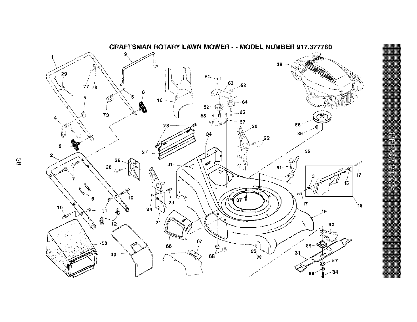
t_
Co
2
J
/
/
77 76
CRAFTSMAN ROTARY LAWN MOWER - - MODEL NUMBER 917,377780
9
61
59- i
22
10
67
17
\
16

CRAFTSMAN ROTARY LAWN MOWER - - MODEL NUMBER 917,377780
{J3
KEY PART
NO. NO.
1 189663;(479
2 I6II05X479
3 186053
4 186079
5 132004
6 66426
7 131959
8 136376
9 182810
10 188821
11 73990500
12 51793
13 186052
16 185855)(428
17 184193
18 187535
19 180911
20 187249)(479
21 187250)(479
22 150078
23 163183
24 73800500
25 161333
26 163409
27 188986
28 88652
29 161586
3I 189028
34 851084
37 150406
36 ---
39 188816
40 168617
KEY PART
DESCRIPTION NO. NO. DESCRIPTION
Handle Upper 4I 85463 Danger DesaF
Handle Lower 57 I79783X004 Bresket Assembly
Spring, Rear Door, RH 58 57808 Screw
Rope Guide / Anti-Fold Bracket 59 184543 Pulley Assembly
Nut. Has. w}th Lockwasher insert 1/4-20 61 145212 Flange Nut
Wire Tie 62 155552 Locknut
Bolt Handle 5t16-18x 1 75 63 179719X004 Idler Arm
Knob Hattie 64 166043 Idler Pulley
Control Bar 65 I60829 Shoulder Bolt
Bolt, Carriage 66 183058X428 Door Assembly
Nut. Has. w}th Lockwasher Insert 5/16-18 UNC 67 169699 Guard. Multi-Cut
HaJrp)n. Cotter 68 88349 Nut. Has
Spr;ng Rear Door LH 73 182003 CI;p
Kit Rear Door (;ncludes Springs) 76 850733X004 Bracket Upstop
Bolt Rear Door 77 750634 Screw
Plag, Mulcher 84 187653 Screw
Kit, Housing 85 187723 Key, Hi-Pro
Handle, Bracket Assembly, Left 86 184941 Pulley
Handle, Bracket Assembly, Right 87 851074 Washer
Screw, Hex Washer Head 88 850263 Washer Lock
Bolt Hex Head 5/I 6-I8 x 5_ 89 I84590 Blade Adapter
Lccknut Hex 90 189185 Debris Shield
Baffle, Side 91 182227 Screw, Machine #8
Screw #12 x 5/8 92 188244 Belt Keeper
Skirt. Rear 93 182228 Nut. Has #8
Screw. Hinge 1/4-20 x 1_25 - - 161058 Warning Decal (Not Shown)
Cable MZR - - 189443 OwneCs Manual
Blade 2I"
Bolt Hex Head AvaElable accessories not included with lawn mower:
Bolt, Engine 71 33623 Gas Can (2.5 Gallon Container)
Engine, Tacumseh, Model Number 71 33500 Fuel Stabilizer
143,046702 (See Breakdown) 71 33000 SAE 30W Oil (20 Ounce Boffie)
Grass Catcher Bag
Grass Catcher Frame NOTE: All ccm_nent dimensions given in U.S. inches.
1irtch = 25.4 mm
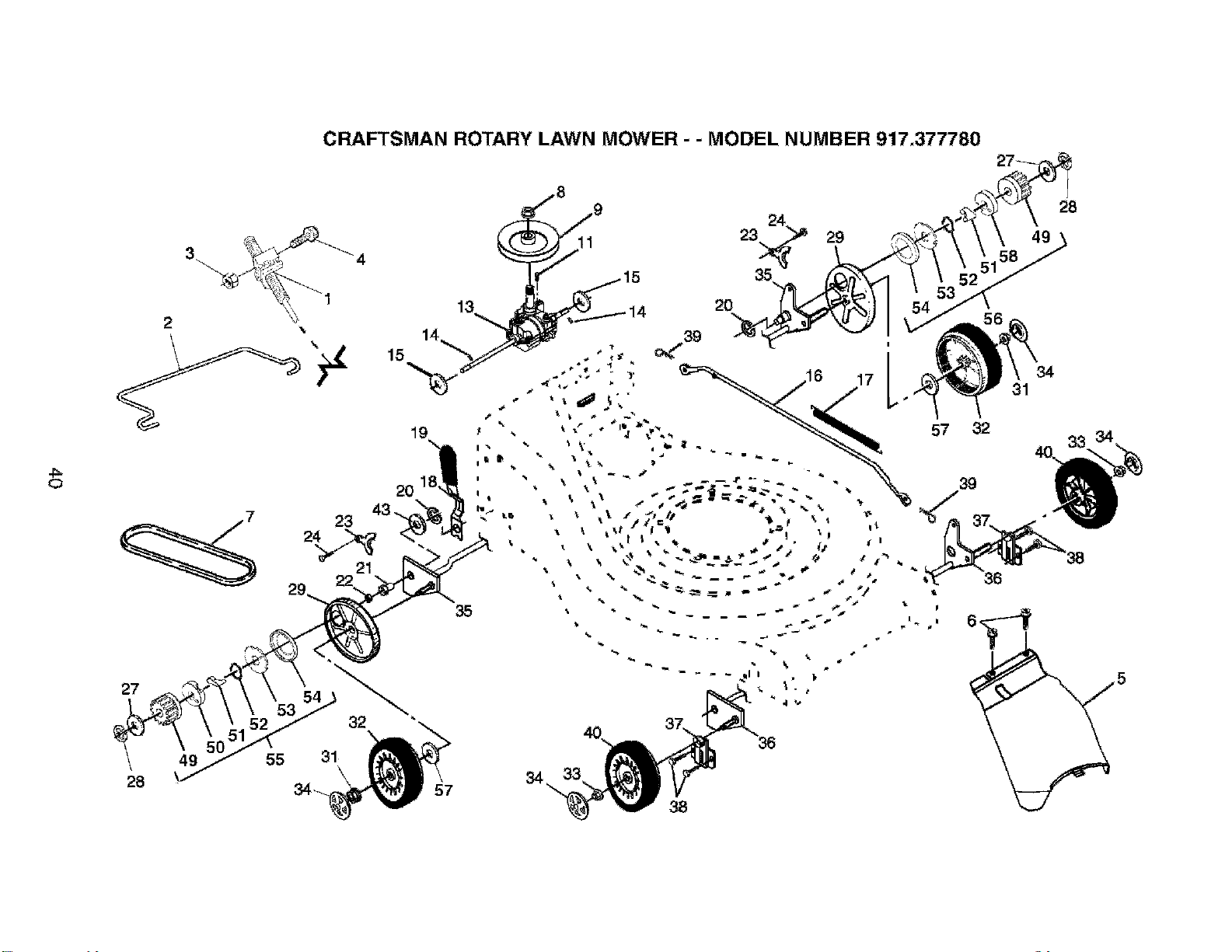
cRAFTSMAN ROTARY LAWN MOWER - " MODEL NUMBER 917,377780
"_ _'_ 1
2 "
31
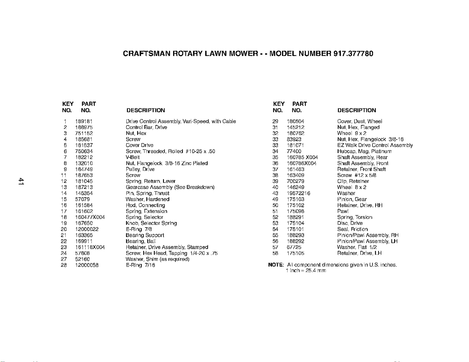
CRAFTSMAN ROTARY LAWN MOWER - - MODEL NUMBER 917,377780
4:_
KEY PART
NO, NO,
1 189181
2 188975
3 751152
4 185681
5 161537
6 750634
7 182212
8 132010
9 184749
11 187653
12 181045
13 187213
14 145354
15 57079
16 161584
17 161602
18 160477)(004
19 167650
20 12000022
2I 163365
22 169911
23 161118X004
24 57808
27 52160
28 12000058
KEY PART
DESCRIPTION NO, NO, DESCRIPTION
Drive Control Assembly, VarbSpeed, with Cable 29 180504
Control Bar, Drive 31 145212
Nut, Hex 32 180762
Screw 33 83923
Cover Drive 33 181071
Screw, Threaded Rolled #10-25 x 50 34 77400
V-Belt 35 160785 X004
Nut, Flangelock 3/8-16 Zinc Plated 36 160786X004
Pulley. Drive 37 161463
Screw 38 163409
Spring Return Lever 39 700279
Gearcase Assembly (See Breakdown) 40 148249
Pin Spring Thrust 43 19572216
Washer, Hardened 49 175103
Rod, Connecting 50 175102
Spring_ Extension 51 175098
Spring_ Selector 52 188291
Knob Selec_r Spring 53 175104
E-Ring 7/8 54 175101
Bearing Supbcrt 55 188293
Bearing, Bail 56 188292
Retainer, Drive Assembly, Stamped 57 67725
Screw. Hex Head, Tapping 1/4-20 x .75 58 175105
Washer Shim (as required)
E-Ring 7/16
Cover, Dust, Wheel
Nut, Hex, Flanged
Wheel 9 x 2
Nut He:< Flangelock 3/8-16
EZ Walk Drive Control Assembly
Hubcap Mag Platinum
Shaft Assembly, Rear
Shaft Assembly, Front
Retainer, Front Shatt
Screw #12 x 5_
Clip Retainer
Wheel 8 x 2
Washer
Pinion, Gear
Retainer, Drive, RH
Pawl
Spring, Torsion
Disc, Drive
Seal Friction
Pinior_'Pawl Aasembly, RH
PinioWPawl Assembly, U-]
Washer, Flat 1/2
Retainer, Drive, LH
NOTE: All combcnent dimensions given in US inches
1tech = 25.4 mm
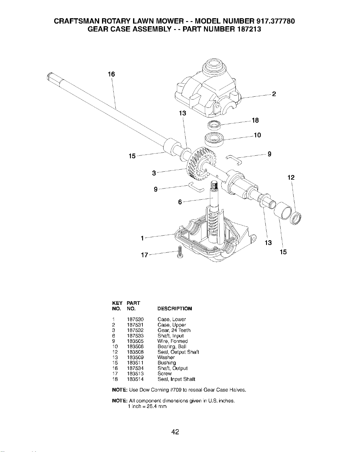
CRAFTSMAN ROTARY LAWN MOWER - - MODEL NUMBER 917.377780
GEAR CASE ASSEMBLY - - PART NUMBER 187213
16
13
12
1
17
13
15
KEY PART
NO. NO. DESCRIPTION
I 187530 Case, Lower
2 187531 Case, Upper
3 187532 Gear, 24 Teeth
8 187533 Shaft, Input
9 183505 Wire, Formed
I0 183506 Bearing, Ball
I2 183508 Seal, Output Shaft
I3 183509 Washer
I5 183511 Bushing
I6 187534 Shaft, Output
17 1835I 3 Screw
I8 183514 Seal, Input Shaft
NOTE: Use Dow Coming #709 to reseal Gear Case Halves.
NOTE: All _mponent dimensions given in U.S. inches.
1 inch = 25.4 mm
42
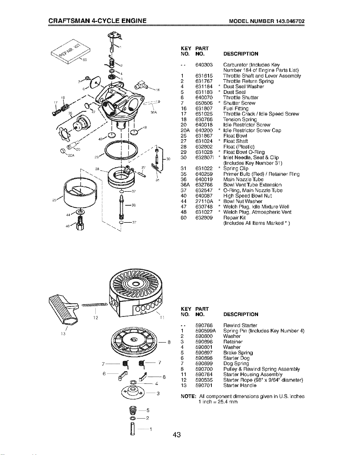
CRAFTSMAN 4-CYCLE ENGINE MODEL NUMBER 143.046702
KEY PART
NO, NO. DESCRIPTION
1
2
4
5
6
7
16
17
18
20
20A
25
27
28
29
-30 30
640303
631615
631767
631184
631183
640070
650506
631807
651025
630766
640018
640200
631867
631024
632802
631028
6328071
81 631022
85 640259
86 640019
86A 632766
37 632547
40 640087
44 271IOA
47 630748
48 631027
60 632609
Carburetor (Includes Key
Number I84 of Engine Parts List)
Throttle Shaft and Lever Assembly
Throttle Return Spring
* Dust Seal Washer
* Dust Seal
Throttle Shutter
* Shutter Screw
Fuel Fitting
Throttle Crack/Idle Speed Screw
Tension Spring
Idle Restrietor Screw
* Idle Restrietor Screw Cap
Float Bowl
* Float Shaft
Float (Plastic)
* Float Bowl O-Ring
* Inlet Needle, Seat & Clip
(Includes Key Number 81)
* Spring Clip
Primer Bulb (Red) / Retainer Ring
Main Nozzle Tube
Bowl Vent Tube Extension
* O-Ring, Main NozzleTube
High Speed Bowl Nut
* Bowl NutWasher
* Welch Plug Idle Mixture Well
* Welch Plug Atmospheric Vent
Repair Kit
(Includes All Items Marked * )
/
13
12 II
KEY PART
NO, NO. DESCRIPTION
-- 590766
1 590599A
2 590600
--8 3 590696
4 590601
5 590697
6 590698
7--_--7 7590699
8 590700
6--_3 _¢_ _ 11 590764
6 12 590535
13 590701
0--2
Rewind Starter
Spring Pin Includes Key Number 4)
Washer
Retainer
Washer
Brake Spring
Starter Dog
Dog Spring
Pulley & Rewind Spring Assembly
Starter Housing Assembly
Starter Rope (98" x 9/64" diameter)
Starter Handle
NOTE: All component dimensions given in U.S. inches
1 inch = 25.4 mm
43
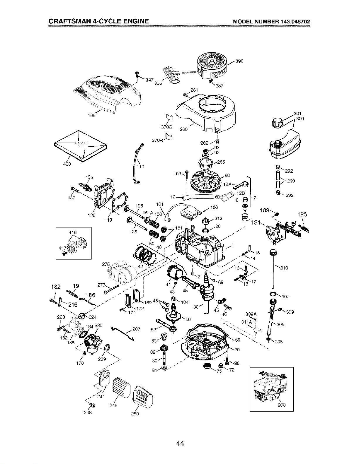
CRAFTSMAN 4-CYCLE ENGINE MODEL NUMBER 143.046702
416 125
275
<
238 250
30
301
290
!_\292
7
• 306
i
-4
900
44
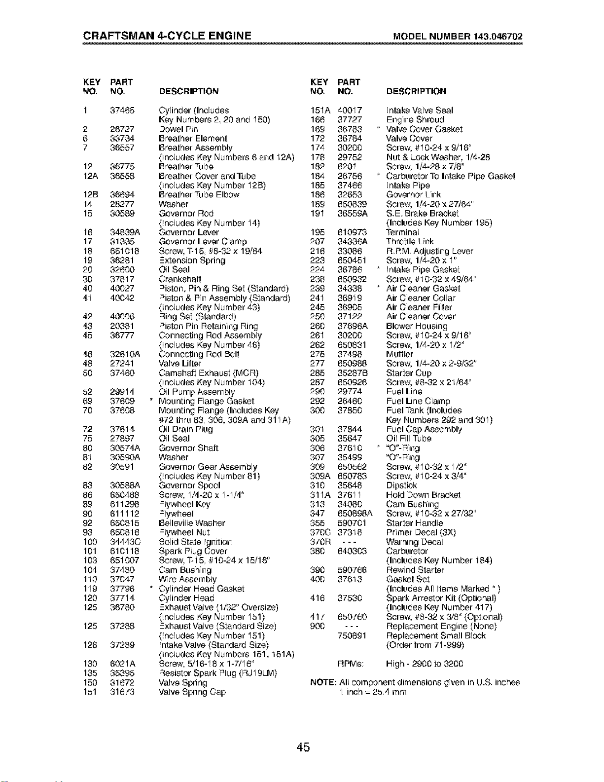
CRAFTSMAN 4-CYCLE ENGINE MODEL NUMBER 143.046702
KEY PART KEY PART
NO, NO, DESCRIPTION NO. NO. DESCRIPTION
1 37465
2 26727
6 33734
7 36557
12 36775
12A 36558
12B 36694
14 28277
15 30569
16 34839A
17 31335
16 651016
19 36281
20 32600
30 37817
40 40027
4I 40042
42 40006
43 20381
45 36777
46 326IOA
46 27241
50 37460
52 29914
69 37609
70 37608
72 37614
75 27897
80 30574A
8I 30590A
82 30591
83 30588A
86 650488
89 611296
90 611112
92 650815
93 650816
100 34443C
101 610116
103 651007
104 37480
110 37047
119 37796
120 37714
125 36760
125 37288
126 37289
130 602IA
135 35395
150 31672
151 31673
Cylinder (Includes 15IA 40017
Key Numbers 2, 20 and I50) 166 37727
Dowel Pin 169 36763 *
Breather Element 172 36764
Breather Assembly 174 30200
(Includes Key Numbers 6 and I2A) 176 29752
Breather Tube 182 620I
Breather C_ver and Tube 184 26756 *
(Includes Key Number I2B) 185 37466
Breather Tube Elbow 186 32653
Washer 189 650639
Governor Rod 19I 36559A
(Includes Key Number I4)
Governor Lever 195 610973
Governor Lever Clamp 207 34336A
Screw, T-15, #8-32 x 19/64 216 33086
Extension Spring 223 650451
Oil Seal 224 36786 *
Crankshaft 238 650932
Piston, Pin & Ring Set (Standard) 239 343,36 *
Piston & Pin Assembly (Standard) 24I 369I 9
(includes Key Number 43) 245 36905
Ring Set (Standard) 250 37122
Piston Pin Retaining Ring 260 37696A
Connecting Rod Aasembly 26I 30200
(includes Key Number 46) 262 650631
Connecting Rod Bolt 275 37498
Valve Lifter 277 650968
Camshaft Exhaust (MCR) 285 35287B
(Includes Key Number I04) 287 650926
Oil Pump Assembly 290 29774
Mounting Flange Gasket 292 26460
Mounting Flange (Includes Key 300 37850
#72 thru 83, 306, 309A and 311A)
Oil Drain Plug 30I 37844
Oil Seal 305 35647
Governor Shaft 306 376I 0 *
Washer 307 35499
Governor Gear Aasembly 309 650562
(Includes Key Number 61) 309A 650763
Governor Spool 310 35648
Screw, I/4-20 x I-I/4" 31IA 376I I
Flywheel Key 313 34080
Flywheel 347 650698A
Belleville Washer 355 590701
Flywheel Nut 370C 37316
Solid State Ignition 370R - - -
Spark Plug Cover 380 640303
Screw, T-15 IH0-24x 15/16"
Cam Bushing 390 590766
Wire Aasembly 400 37613
Cylinder Head Gasket
Cylinder Head 416 37530
Exhaust Valve (I/32" Oversize)
(includes Key Number I51) 417 650760
Exhaust Valve (Standard Size) 900 - - -
(includes Key Number I51) 750891
Intake Valve (Standard Size)
(includes Key Numbers 151, I51A)
Screw, 5/16-I 8 x 1-7/I 6"
Resistor Spark Plug (RJI9LM)
Valve Spring
Valve Spring Cap
Intake Valve Seal
Engine Shroud
Valve Cover Gasket
Valve Cover
Screw, #I 0-24 x 9/16"
Nut & LockWasher, 1/4-28
Screw, 1/4-28 x 7/6"
Carburetor To Intake Pipe Gasket
Intake Pipe
Governor Link
Screw, 1/4-20 x 27/64"
S.E. Brake Bracket
(Includes Key Number 195)
Terminal
Throttle Link
R.PM Adjusting Lever
Screw, 1/4-20 x I"
Intake Pipe Gasket
Screw, #I 0-32 x 49/64"
Air Cleaner Gasket
Air Cleaner C_llar
Air Cleaner Filter
Air Cleaner C_ver
Blower Housing
Screw, #I 0-24 x 9/16"
Screw, 1/4-20 x I/2"
Muffler
Screw, 1/4-20 x 2-9/32"
Starter Cup
Screw, #6-32 x 21/64"
Fuel Line
Fuel Line Clamp
Fuel Tank (Includes
Key Numbers 292 and 30I)
Fuel Cap Assembly
Oil Fill Tube
"O°.Ring
"O"-Ring
Screw, #I 0-32 x I/2"
Screw, _tl0-24 x 3/4"
Dipstick
Hold Down Bracket
Cam Bushing
Screw, #I 0-32 x 27/32"
Starter Handle
Primer Decal (3X)
Warning Decal
Carburetor
(Includes Key Number 164)
Rewind Starter
Gasket Set
(Includes All Items Marked _)
Spark Arrestor Kit (Optional)
(Includes Key Number 4I 7)
Screw, #6-32 x 3/6" (Optional)
Replacement Engine (None)
Replacement Small Block
(Order from 71-999)
RPMs: High - 2900 to 3200
NOTE: All component dimensions given in U.S. inches
I inch = 25.4 mm
45

SERVICE NOTES
46

SERVICE NOTES
47

Your Home
For repair - in your home - of all major brand appliances,
lawn and garden equipment, or heating and cooling systems,
no matter who made it, no matter who sold it!
For the replacement parts, accessories and
owner's manuals that you need to do-it-yourself.
For Sears professional installation of home appliances
and items like garage door openers and water heaters.
1-800-4-MY-HOME ® Anytime, day or night
(1-800-469-4663) (U.S.A. and Canada)
www.sears.corn www.sears.ca
Our Home
For repair of carry-in products like vacuums, lawn equipment,
and electronics, call or go on-line for the nearest
Sears Parts and Repair Center.
1-800-488-1222 Anytime, day or night (U.S.A. enly)
www,sears.com
To purchase a protection agreement (U.S.A.)
or maintenance agreement (Canada) on a product serviced by Sears:
1-800-827-6655 (U.S.A.) 1-800-361-6665 (Canada)
Pare pedir se_cio de reparaci6n
a domicilio, y pare ordenar piezas:
1-888-SU-HOGAR sM
(1-e88-784-6427)
Au Canada pour se_ce en frangais:
1-SO0-LE-FOYER _c
(1-8C0-5&3-6937)
www.sears.oa
SEARS
@Sears,R_ endCo.
® Registered Trademark / r_l Trademark / S_lService Mark of Sears, Roebuck and Co.
® Marca Registrada / __'_Marea de F_briea / s_aMarea de Servieio de Sears, Roebuck and Co.
macMarque de commerce/_D Marque d_pos_e de Sears, Roebuck and Co.
189443 12.13.03 BY Printed in U.S.A.