Loading ...
Loading ...
Loading ...
If not, rotate the tilt hand wheel clockwise until the poifxtx_•. :_
ter indicates approximately 25 degrees on the tilt gage, i
Loosen the two set screws m the stop collar nearest the
end of the tilt screw (Key No. 55, fig. 1) and repeat
the previous method of adjusting this stop collar until
the blade makes an angle of 45 de_grees to the table top.
Your saw is oow set to give a positive stop at 0 degrees
and at 45 degrees.
MOUNTING THE MOTOR _ Mount the motor (see
Motor Specifications) to the motor mount assembly (N,
fig. 2) -- then mourn the motor support assembly to the
saw by sliding the two pins (O, fig. 2) into the mounting
holes at the rear of the cradle. Place pulley (S, fig. 2)
on the motor shaft, line it up with the pullev on the saw
=.,-.,.. oh,.. );,_h,_,, the pu!le_," -"t screws. In.-. V.belt
(T, fig. 2) over pulleys and adjust the belt tenslon b)'
moving the motor support assembly towards or away from
the cradle. Motor should be allowed to rest or hang
against the belt to obtain the automatic belt tightening
feature-- and belt should be snug. If adjustment is cor-
rect, clamp the motor support in place by tightening the
two hex. head machine screws (Key No. 115, fiR. II
which are packed in the envelope in the loose parts
carton.
ADJUSTING MOTOR MOUNT TENSION--Tension
is adjusted by tightening the screw (Key No. 49, fig. 1),
against the steel washer (Key No. 47, fig. l) and the
spring washer (Key No. 48, fig. 1). Screw should be
tightened just enough to reduce motor vibration when
saw is operating. Do NOT tighten screw to a locked
position, or it will be sheared off when blade is raised
or lowered. A sliding action is necessary because mount
changes position as blade is raised or lowered. Operate
the saw by hand to make certain that the belt has proper
tension and that mount changes position as it should.
If saw is to be driven by a large frame motor that cannot
be mounted on the motor support assembly, mount the
motor on motor rails.
PLACEMENT OF MITER GAGE _ The miter gage as-
sembly (K, fig. 2) can be used in either one of the two
table grooves.
This saw is designed to be used with a 3450 rpm motor.
Motor should be 3/4 bp (for Light duty) or one hp (for
heavy duty)-in either an AC motor of a repulsion-
induction or capacitor type, or a compound-wound DC.
The motor shaft center should be approximately 4-5/8
inches above the bottom of the motor base. If this dimen-
sion varies appreciably from 4-5/8 inches, it may be neces-
sary to obtain a belt of a different length. If a 1750 rpm
motor with a 4-5/8 inch shaft center height is used a 5
inch pulley is required. This will require one 1/2 inch
V-belt.
CAUTION
Under no circUmstances should a 5 inch motor
pulley be used with a 3450 rpm motor. The saw
blade speed resulting from such a pulley ratio
would be dangerous. Do not use a 2-Ill inG,
motor pulley with a 1750 rpm motor-this will
not give satisfactory saw performance.
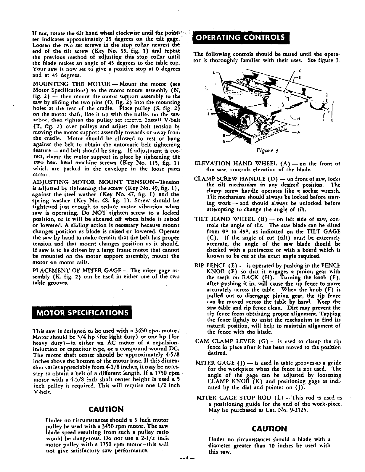
The following controls should be tested until the opera-
tor is thoroughly familiar with their uses.
__ -K
-r
See figure 3,
Figure 3
ELEVATION HAND WHEEL (A)--on the front of
the saw, controls elevation of the blade.
CLAMP SCREW HANDLE (D) -- on front of saw, locks
the tilt mechanism in any desired position. The
clamp screw handle operates like e socket wrench.
Tilt mechanism should always be locked before start-
ing work- and should always be unlocked before
attempting to change the angl e of tilt.
TILT HAND WHEEL (B) --on left side of saw, con-
trols the angle of tilt. The saw blade can be tilted
from 0° to 45 °, as indicated On the TILT GAGE
(C). If the angle of cut (tilt) mu_t be extremely
accurate, the angle of the saw blade should be
checked with a protractor or with a board which is
known to be cut at the exact angle required.
RIP
FENCE (El -- is operated by pushin_g !n the FENCE
KNOB (F) so that it engages a proton gear with
the teeth on RACK (H). Turning the knob (F),
after _pushmg it in, will cause the rip fence to move
accurately across, the table.. When the knob (F) is
pulled out to dtsengage pinion gear, the rap fence
can be moved across the table by hand. Keep the
saw table and rip fence clean. Dirt may prevent the
rip fence from obtaining proper alignment. Tapping
the fence lightly to assist the mechanism to find its
natural position, will help to maintain alignment of
the fence with the blade.
(.'AM CLAMP LEVER (G)--is used to clamp the rip
fence m place after it has been moved to the position
desired.
MITER GAGF (J)- is used in table grooves as a guide
for the workpiece when the fence is not used. The
angle of the gage can be adjusted by loosening
CLAMP KNOB (K) and positioning gage as indi-
cated by the dial and pointer on (J).
MITER GAGE STOP ROD (L) -This rod is used as
a positioning guide for the end of the work-piece.
May be purchased as Cat. No. 9-2125.
--$P
CAUTION
Under no circumstances should a blade with a
diameter greater than 10 inches be used with
this saw.
Loading ...
Loading ...
Loading ...