OPERATING INSTRUCTIONS
AND PARTS LIST FOR
CRAFTSMAN BENCH SAW
10-INCH TILTING ARBOR
MODEL NUMBER i13.29991
The above Model Number will be found on a plate attached to your
saw, at the back, near the bottom of the base. Always mention the
Model Number when communicating with us regarding your saw or
when ordering parts.
HOW TO ORDER REPAIR PARTS
All parts listed herein may be ordered through Sears, Roebuck and Co.
o...... p_y,,o-.,e,_r° Limit._d. When ordering parts by mail from the mail
order house which serves the territory in which you live, selling prices
will be furnished on request or parts will be shipped at prevailing prices
and you will be billed accordingly.
WHEN ORDERING REPAIR PARTS, ALWAYS GIVE THE FOLLOW-
ING INFORMATION AS SHOWN IN THIS LIST:
1. The PART NUMBER 3. The MODEL NUMBER 113.29991
2. The PART NAME 4. The NAME of item--lO INCH BENCH SAW
COAST TO COAST NATION-WIDE
SERVICE FROM SEARS
FOR YOUR CRAFTSMAN BENCH SAW
SEARS, ROEBUCK AND CO. and
SIMPSONS-SEARS LIMITED in Canada
back up your investment with quick,
expert mechanical service and genu-
ine CRAFTSMAN replacement parts.
If and when you need repairs or serv-
ice, call on us to protect your invest-
ment in this fine piece of equipment.
SEARS, ROEBUCK AND CO.- U. S. A.
IN CANADA, SIMPSONS-SEARS LIMITED
Printed in U.S.A.
CRAFTSMAN BENCH SAW, 10 INCH TILTING ARBOR, MODEL NO. 113.29991
,m i
29 27
65
67
77
I00
--2--
Figure I
CRAFTSMAN BENCH SAW,
10 INCH TILTING ARBOR MODEL NO. 113.29991
WHEN ORbERING REPAIR PARTS, ALWAYS GIVE THE FOLLO_F1NG
INFORMATION AS SHOWN IN THIS LIST:
1. The PART NUMBER.
2. The PART NAME.
3. The MODEL /_UMBER--II3.29991.
4. The NAME of item-10 _ Bench Saw.
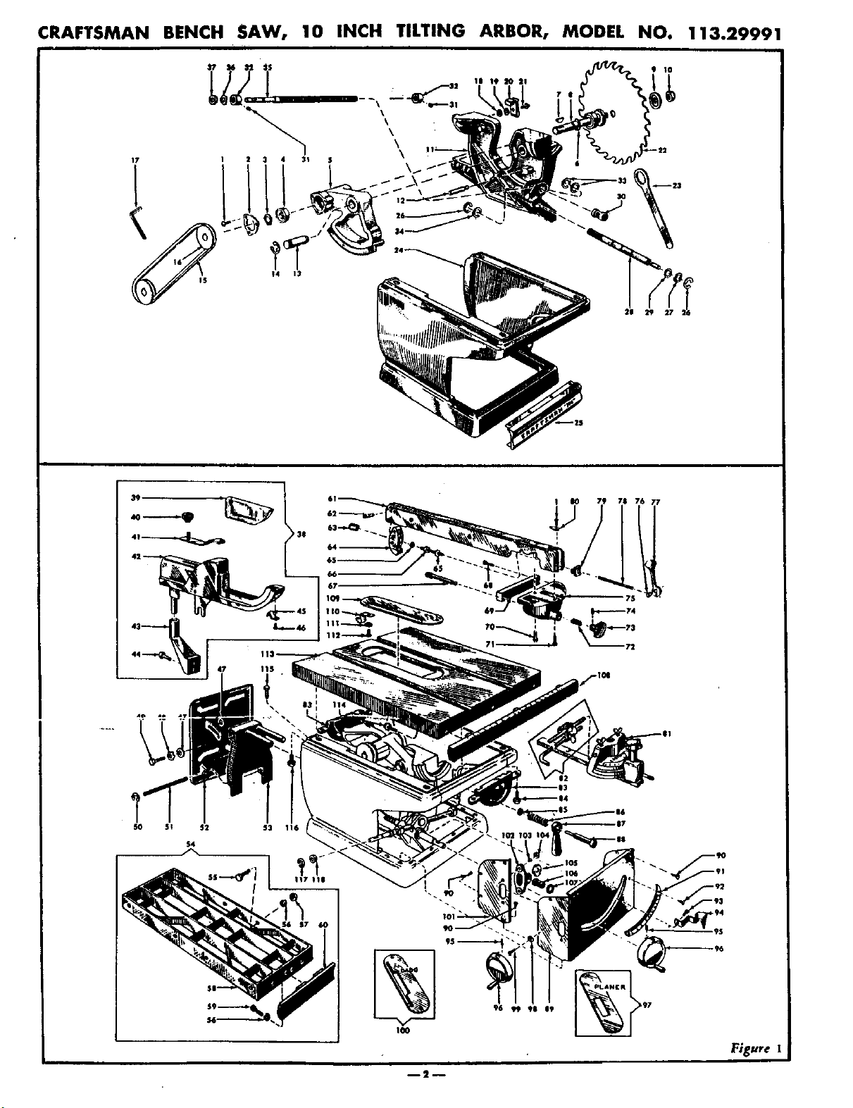
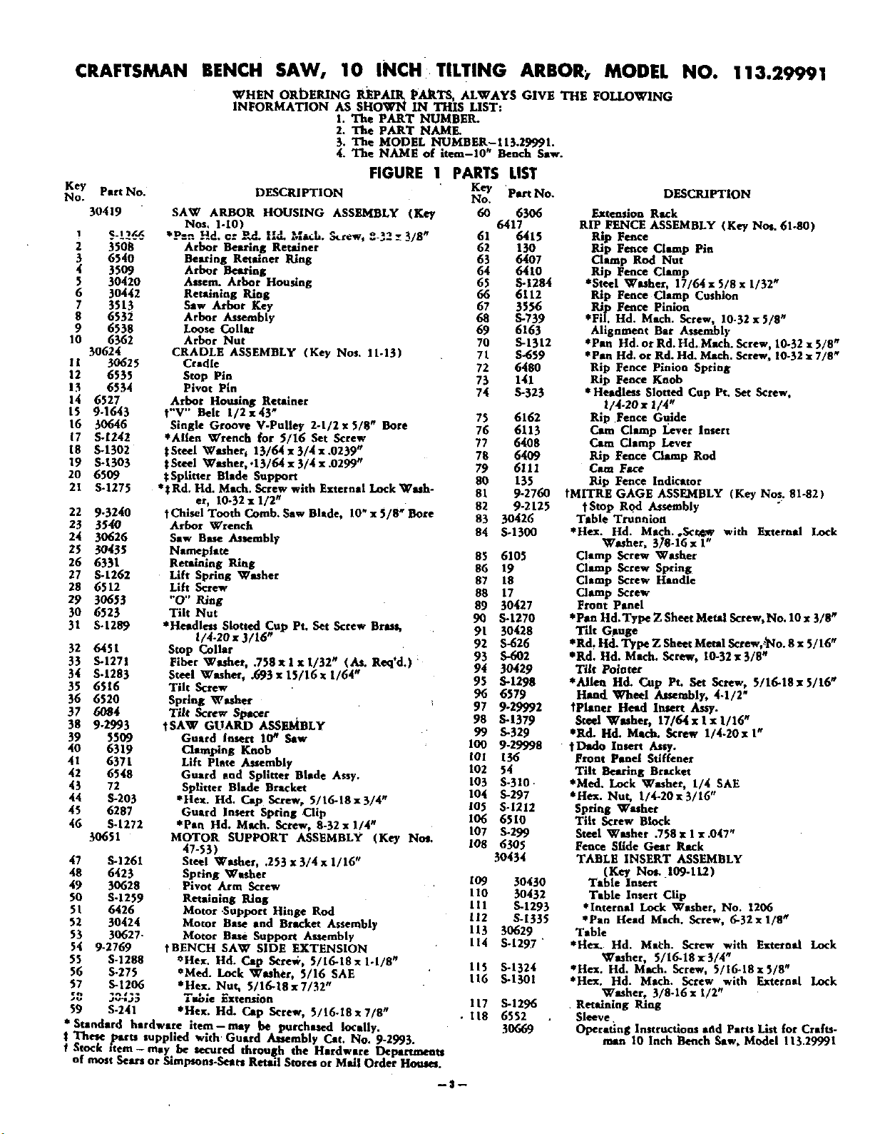
FIGURE 1
Key
No. DESCRIPTION
PARTS LIST
Key Part No.
Part No. No,
30419 SAW ARBOR HOUSING ASSEMBLY (Key 60 6306
Nos, I-I0) 6417
...... -.... /8 61 6415
2 3508 Arbor Bearing Retainer 62 130
3 6540 Bearing Retainer Ring 63 6407
4 3509 Arbor Bern'lug • 64 6410
5 30420 Assera. Arbor Housing 65 S-1284
6 30442 Retaining Ring 66 6112
7 3513 Saw Arbor Key 67 3556
8 6532 Arbor Atsembiy 68 S-739
9 6538 Loose Collar 69 6163
10 6362 Arbor Nut 70 S-1312
30624 CRADLE ASSEMBLY (Key Nos. 11-13) 71 5-659
I 1 30625 Cradle 72 6480
12 6535 Stop Pin 73 141
13 6534 Pivot Pin
14 6527 Arbor Housing Retainer 74 5-323
15 9-1643 t V Belt 1/2x43" 75 6162
16 30646 Single Groove V.Pulley 2-1/2 x 5/8" Bore 76 6113
17 5.1242 *Alien Wrench for 5/16 Set Screw 77 6408
18 5-1302 gSteel Wmher, 13/64x3/4x.0239" 78 6409
19 S-1303 ; Steel Washer,.13/64 x 3/4 x .0299" 79 6111
20 6509 gSplltrer Blade Support 80 135
21 S-1275 *_Rd. Hd. Mech. Screw with External Lock Wmh- 81 9-2760
er, 10-32x 1/2"
82 9-2125
22 9-3240 tChisel Tooth Comb. Sew Blade, 10" x 5/8" Bore 83 30426
23 35_0 Arbor Wrench 84 S-1300
24 30626 Sew Base Assembly
25 30435 Nameplate 85 6105
26 633l Retaining Ring 86 19
27 S-1262 Lift Spring Washer 87 18
28 6512 Lift Screw 88 17
29 30653 "0" Ring 89 30427
30 6523 Tilt Nut 90 S-I270
31 S-1289 *Headless Slotted Cup Pt. Set Screw Brass, 91 30428
1/4.20 x 3/16" 92 S-626
32 6451 Stop Collar
33 S-1271 Fiber Washer, .758xlxI/32" (As. Req'd.) " 93 S-602
3_ S-1283 Steel Washer, .693 x 15/16 x 1/64" 94 30429
93 S-1298
35 6516 Tilt Screw 96 6579
36 6520 Spring Washer _ 97 9-29992
37 60_4 Tilt Screw Spacer
38 9-2993 tSAW GUARD ASSEMBLY 98 S-1379
99 S-329
39 5309 Guard Insert 10 _ Saw 100 9-29998
40 6319 Clamping Knob 101 136
41 6371 Lift Plate Assembly 102 54
42 6548 Guard end Splitter Blade Assy, 103 S-310.
43 72 Splitter Blade Bracket
44 S-203 *Hex. Hd. Cap Screw, 5/16-18x3/4" 104 S-297
105 S-1212
45 6287 Guard Insert Spring Clip 106 6510
46 S-1272 *Pan Hd. Mach. Screw, 8-32 x 1/4 # 107 S-299
30651 MOTOR SUPPORT ASSEMBLY (Key No*.
47-53) IO8 6305
47 S-1261 Steel Washer, .253 x 3/4 x 1/16" 30434
48 6423 Spring Washer 109 30430
49 30628 Pivot Arm Screw
50 S-1259 Retaining Ring 110 30432
51 6426 Motor Support Hinge Rod 111 S-1293
52 30424 Motor Base and Bracket Assembly 112 S-1335
113 30629
53 30627- Motor Bmm Support Asaembly 114 S-1297 "
54 9-2769 tBENCH SAW SIDE EXTENSION
55 S-1288 CHex. Hd. Cap Serev:,, 5/16-18x 1-1/8" 115 S-1324
56 S-275 *Ned. lock Wmher, 5/16 SAE 116 S-1301
57 S-1206 aHex. Nut, 5/16-18x7/32"
_.,_J_ T_ie Extension 117 S-1296
59 S-241 *Hen. Hd. Cap Screw, 5/16.18x7/8 # • I|8 6552
• Standard hardware item--mey be purchased locally. 30669
t These parts supplied with Guard Atsembly Cat. No. 9-2993.
f Stock item - may. be secured through the Hardware Departments
of most Sears or Stmpsons-Seart Retail Stores or Mail Ogden Home*.
DESCRIPTION
Extension Rack
RIP PENCE ASSEMBLY (Key Not. 61.80)
Ri_.P Fence
p Fence Clamp Pin
Clamp Rod Nut
Rip Fence Clamp
*Steel Washer, 17/64 x 5/8 x 1/32 #
Rip Fence Clamp Cushion
Rip Fence Pinion
*Fil. Hd. Mech. Screw, 10-32 x 5/8"
Alignment Bar As_embl 1,
*Pan Hd. or Rd. Hd. Mech. Screw, 10-32 x 5/8 #
*Pan Hd. or Rd. Hd. Mech. Screw, 10-32 • 7/8 #
Rip Pence Pinion Spring
Rip Fence Knob
* Headless Slotted Cup Pt. Set Serew,
1/4-20 x 1/4#
Rip Fence Guide
Cam Clamp I_ever Insert
Cam Clamp Lever
Rip Fence Clamp ROd
Cam Face
Rip Fence Indicator
tMITRE GAGE ASSEMBLY (Key Nos. 81-82)
tStop Rod Assembly
Table Trunnion
*Hex. Hd. Mech. ,Scrr_w with External Lock
Washer, 3/'8-16 x 1"
Clamp Screw Washer
Clamp Screw Spring
Clamp Screw Handle
Clamp Screw
Front Panel
*Pan Hd.Type Z Sheet Metal Screw, No. 10 x 3/8"
T'dt Ojmge
*Rd. ltd. "I_pe Z Sheet Metal Screw,_No. 8 x 5/16 W
*Rd. Hd. Math. Screw, 10-32 x 3/8 #
Tilt Polater
*Alien Hd. Cup Pt. Set Screw, 5/16-18 x 5/16"
Hand _Vheel Alterably, 4-1/2"
TPhmer Head Insert Assy.
Steel Wmher, 17/64 x I x 1/16 #
*Rd. Hal. Mech. Screw 1/4.20x I"
t Dado Insert Atty.
Pront Panel Stiffener
Tilt Bearing Bracket
*Med. Lock Washer, 1/4 SAE
*Hex. Nut, !/4-20x3/16"
Spring Wmher
Tiis Screw Block
Steel Washer .758 x 1 x .047"
Pence Slide Gear Rack
TABLE INSERT ASSEMBLY
(Key No_ .109.11.2)
Table Insert
Table Insert Clip
*Internal Lock Washer, No. 1206
*Pan Head Mech. Screw, 6-32x 1/8 #
Table
*Hex. Hd. Ma_:h. Screw with External Lock
Washer, 5/16-18 x 3/4 #
*Hex. Hd. Mech. Screw, 5/16-18x5/8"
*Hex. Hd. Mech. Screw with External Lock
Washer, 3/8-16 • I/2"
Retaining Ring
Sleeve
Operatlng Instructions at_d Parts List for Crafts-
man 10 Inch Bench Saw, Model 113.29991
-$--
InstructionsIorAssemblingandOperatingYourSaw
A LE F H G M
T V D J
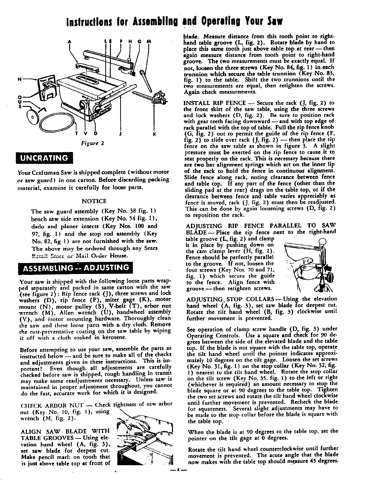
Fi[ure 2
Your Craftsman Saw is shipped complete (without motor
or saw guard) in one carton. Before discarding packing
nmterial, examine it carefully for loose parts.
NOTICE
The saw guard assembly (Key No. 38 fig. 1)
bench saw side extension (Key No. 54 fig. 1),
dado and planer inserts (Key Nos. 100 and
97, fig. 1) and the stop rod assembly (Key
No. 82, fig 1 ) are not furnished with the saw.
The above may be ordered through any Sears
!_c:ail S_c,re or Mail O,d_r House.
Your saw is shipped with the following loose parts wrap-
ped separately and packed in same carton with the saw
(see figure 2): Rip fence rack (J), three screws and lock
washers (D) rip fence (F), mlter gage (K),. motor
mount (N), motor pulley (S), V-belt (T), arbor nut
wrench (M), Allen wrench (U), handwheel assembly
('st), and fiiotor mounting hardware. Thoroughly clean
the saw and these loose parts with a. dry cloth. Remove
the rust-preventative coating on the saw table by wiping
it off with a cloth soaked in kerosene.
Before attempting to use your saw, assemble the parts as
instructed below-- and be sure to make all of the checks
and adjustments given in these instructions. This is im-
portant! Even though all adjustments are carefully
checked before saw is shipped, rough handling in transit
may make some readjustments necessary. Unless saw is
maintained in proper adjustment throughout, you cannot
do the fast, accurate work for which it is designed.
CIIECK ARBOR NUT -- Check tightness of saw arbor
out (Key No. 10, fig. 1), using _-_
wrench (M, fig. 2).
ALIGN SAW BLADE wITH
TABLE GROOVES--Using ele-
vation hand wheel (A, fig. 3),
set saw blade for deepest cut.
Make pencil marl: on tooth that
is just above table top at front of
blade. Measure distance from this tooth point to right-
hand table groove (L, fig. 2). Rotate blade by hana to
place thus same tooth just above table top at rear- then
a-gain measure distance from tooth point to rlght-hand
groove. The two measurements must he exactly equal. If
not, loosen the three screws (Key No. 84, fig. 1) in each
trunnion which secure the table trunnion (Key No. 83,
fig. I) to the table. Shift the two trunnions until the
two measurements are equal, then retighten the screws.
Again check measurements.
INSTALL RIP FENCE -- Secure the rack (J, fig. 2) to
the front skirt of the saw table, using the three screws
and lock washers (D, fig. 2). Be sure to position rack
with gear teeth facing downward -- and with top edge of
rack parallel with the top of table. Pull the rip fence knob
(G, fig. 2) out to permit the guide of the rip fence (F,
fig. 2) to slide over rack (J, fig. 2) -- then place the rip
fence on the saw table as shown in figure 3. A slight
pressure must be exerted on the rip fence to cause it to
seat properly on the rack. This is necessary because there
are two bar alignment springs which act on the inner lip
of the rack to hold the fence in continuous alignment.
Slide fence along rack, noting clearance between fence
and table top. If an)' part of the fence (other than the
sliding pad at the rear) drags on the table top, or if the
clearance between fence and table vanes apprectably as
fence is moved, rack (J, fig. 2) must then be readjusted.
This can be done by again loosening screws (D, fig. 2)
to reposition the rack.
ADJUSTING RIP FENCE PARALLEL TO SAW
BLADE--Place the tip fence next to the right-hand
table groove (L, fig. 2) and clamp
tt m place by pushing down on
the cam clamp le, er (H, fig. 2).
Fence should be perfectly parallel
to the groove. If not, loosen the -'_
four screws (Key Nos. 70 and 71,
fig. 1) which secure the guide
to the fence. Align fence with
groove--then retighten screws.
ADJUSTING. STOP COLLARS--Using the elevation
hand wheel (A, fig. 3), set saw blade for deepest cut.
Rotate the tilt hand wheel (B, fig. 3) clockwise until
further movement is prevented.
See operation of clamp screw handle (D, fig. 3) under
Operating Controls. Use a square and check for 90 de-
grees between the side of the elevated blade and the table
top. If the blade is not square with the table top, operate
the tilt hand wheel until the pointer indicates approxi-
mately 10 degrees on the tilt gage. Loosen the set screws
(Key No. 31, fig. l ) on the stop collar (Key No. 32, fig.
1) nearest to the tilt hand wheel. Rotate the stop collar
on the tilt screw (Key No. 55, fig. 1) to the left or right
(whichever is required) an amount necessary to stop the
blade square or at 90 degrees to the table top. Tighten
the two set screws and rotate the tilt hand wheel clocxwise
until further movement is prevented. Recheck the blade
for squareness. Several shght adjustments may have to
be made to the stop collar before the blade is square with
the table top.
When the blade is at 90 degrees to the table top, set the
pointer on the tilt gage at 0 degrees.
Rotate the tilt hand wheel counterclockwise until further
movement is _preveoted. The acute angle that the blade
now makes with the tab e top should mgasure 45 degrees.
--4--
If not, rotate the tilt hand wheel clockwise until the poifxtx_•. :_
ter indicates approximately 25 degrees on the tilt gage, i
Loosen the two set screws m the stop collar nearest the
end of the tilt screw (Key No. 55, fig. 1) and repeat
the previous method of adjusting this stop collar until
the blade makes an angle of 45 de_grees to the table top.
Your saw is oow set to give a positive stop at 0 degrees
and at 45 degrees.
MOUNTING THE MOTOR _ Mount the motor (see
Motor Specifications) to the motor mount assembly (N,
fig. 2) -- then mourn the motor support assembly to the
saw by sliding the two pins (O, fig. 2) into the mounting
holes at the rear of the cradle. Place pulley (S, fig. 2)
on the motor shaft, line it up with the pullev on the saw
=.,-.,.. oh,.. );,_h,_,, the pu!le_," -"t screws. In.-. V.belt
(T, fig. 2) over pulleys and adjust the belt tenslon b)'
moving the motor support assembly towards or away from
the cradle. Motor should be allowed to rest or hang
against the belt to obtain the automatic belt tightening
feature-- and belt should be snug. If adjustment is cor-
rect, clamp the motor support in place by tightening the
two hex. head machine screws (Key No. 115, fiR. II
which are packed in the envelope in the loose parts
carton.
ADJUSTING MOTOR MOUNT TENSION--Tension
is adjusted by tightening the screw (Key No. 49, fig. 1),
against the steel washer (Key No. 47, fig. l) and the
spring washer (Key No. 48, fig. 1). Screw should be
tightened just enough to reduce motor vibration when
saw is operating. Do NOT tighten screw to a locked
position, or it will be sheared off when blade is raised
or lowered. A sliding action is necessary because mount
changes position as blade is raised or lowered. Operate
the saw by hand to make certain that the belt has proper
tension and that mount changes position as it should.
If saw is to be driven by a large frame motor that cannot
be mounted on the motor support assembly, mount the
motor on motor rails.
PLACEMENT OF MITER GAGE _ The miter gage as-
sembly (K, fig. 2) can be used in either one of the two
table grooves.
This saw is designed to be used with a 3450 rpm motor.
Motor should be 3/4 bp (for Light duty) or one hp (for
heavy duty)-in either an AC motor of a repulsion-
induction or capacitor type, or a compound-wound DC.
The motor shaft center should be approximately 4-5/8
inches above the bottom of the motor base. If this dimen-
sion varies appreciably from 4-5/8 inches, it may be neces-
sary to obtain a belt of a different length. If a 1750 rpm
motor with a 4-5/8 inch shaft center height is used a 5
inch pulley is required. This will require one 1/2 inch
V-belt.
CAUTION
Under no circUmstances should a 5 inch motor
pulley be used with a 3450 rpm motor. The saw
blade speed resulting from such a pulley ratio
would be dangerous. Do not use a 2-Ill inG,
motor pulley with a 1750 rpm motor-this will
not give satisfactory saw performance.
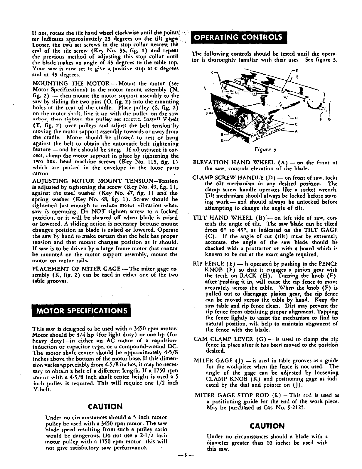
The following controls should be tested until the opera-
tor is thoroughly familiar with their uses.
__ -K
-r
See figure 3,
Figure 3
ELEVATION HAND WHEEL (A)--on the front of
the saw, controls elevation of the blade.
CLAMP SCREW HANDLE (D) -- on front of saw, locks
the tilt mechanism in any desired position. The
clamp screw handle operates like e socket wrench.
Tilt mechanism should always be locked before start-
ing work- and should always be unlocked before
attempting to change the angl e of tilt.
TILT HAND WHEEL (B) --on left side of saw, con-
trols the angle of tilt. The saw blade can be tilted
from 0° to 45 °, as indicated On the TILT GAGE
(C). If the angle of cut (tilt) mu_t be extremely
accurate, the angle of the saw blade should be
checked with a protractor or with a board which is
known to be cut at the exact angle required.
RIP
FENCE (El -- is operated by pushin_g !n the FENCE
KNOB (F) so that it engages a proton gear with
the teeth on RACK (H). Turning the knob (F),
after _pushmg it in, will cause the rip fence to move
accurately across, the table.. When the knob (F) is
pulled out to dtsengage pinion gear, the rap fence
can be moved across the table by hand. Keep the
saw table and rip fence clean. Dirt may prevent the
rip fence from obtaining proper alignment. Tapping
the fence lightly to assist the mechanism to find its
natural position, will help to maintain alignment of
the fence with the blade.
(.'AM CLAMP LEVER (G)--is used to clamp the rip
fence m place after it has been moved to the position
desired.
MITER GAGF (J)- is used in table grooves as a guide
for the workpiece when the fence is not used. The
angle of the gage can be adjusted by loosening
CLAMP KNOB (K) and positioning gage as indi-
cated by the dial and pointer on (J).
MITER GAGE STOP ROD (L) -This rod is used as
a positioning guide for the end of the work-piece.
May be purchased as Cat. No. 9-2125.
--$P
CAUTION
Under no circumstances should a blade with a
diameter greater than 10 inches be used with
this saw.
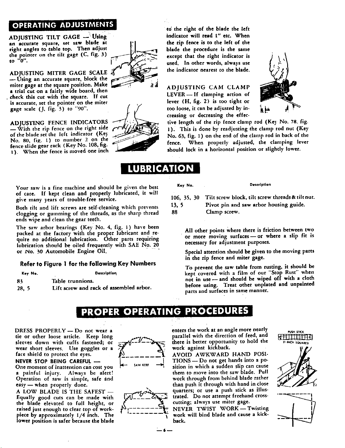
ADJUSTING TILT GAGE _USing
saw blade at
an accurate square, set
right angles to table top. Then adjust
the pointer on the tilt gage (C, fig. 3)
to "0".
ADJUSTING MITER GAGE SCALE
--Using an accurate square, block the
miter gage at the square position. Make
a trial cut on a fairly wide board, then
• check this cut with the square. If cut
is accurate, set the pointer on the miter
gage scale (J, fig. 3) to "90".
ADJUSTING FENCE INDICATORS
I With the rip fence o,1 the right side
of the blade set the left indicator (Ke)
No. 80, fi_. 1) to number 2 on the
fence slide gear rack ( Key No. 108, fig.
I). When the fence is moved one inch
to' the right of the blade the left
indicator will read t" etc. When
the rip fence is to the left of the
blade the procedure is the same
except that the right indicator is
used. In other words, always use
the indicator nearest to the blade.
ADJUSTING CAM CLAMP
LEVER--if clamping action of
lever (H, fig. 2) is too tight or
too loose, it can be adjusted by in- _ _ _ ,
creasing or decreasing the effec-
tive length of the rip fence clamp rod (Key No. 78, fig.
1). This is done by readjusting the clamp rod nut (Key
No. 63, fig. 1) on the end of the clamp rod in back of the
fence. When properly adjusted, the clamping lever
should lock in a horizontal position or slightly lower.
Your saw is a fine machine and should be given the best
of care. If kept clean and properly lubricated, it will
gixe many }'ears of trouble-free service.
Both tilt and lift screws are self-cleaning which prevents
clogging or gumming of the threads, as tile sharp thread
ends wipe and clean the gear teeth.
The saw arbor bearings (Key No. 4, fig. J) base been
packed at the factory with the proper lubricant and re-
quire no additional lubrication. Other parts requiring
lubrication should be oiled frequently with SAE No. 20
or rio. 30 Automobile Engine Oil.
Refer to Figure 1 for the following Key Numbers
Key NO. Description
83 Table trunnions.
28, 5 Lift screw and rack of assembled arbor.
Key No.
106, 35, 30
13, 5
88
Detcription
Tilt screw block, tilt screw threads & tilt nut.
Pivot pin and saw arbor housing guide.
Clamp screw.
All other points Where there is friction between two
or more moving surfaces--or where a sllp fit is
necessary for adjustment purposes.
Special attention should be given to the moving parts
in the rip fence and miter gage.
To prevent the saw table from rusting, it should be
kept covered with a film of our "'Stop Rust" when
not in use- and should be wiped off with a cloth
before using. Treat other unplated and unpainted
parts and surfaces in same manner.
DRESS PROPERLY--Do not wear a
tie or other loose article• Keep long
sleeves down with cuffs fastened; or
wear short sleeves. Use goggles or a
face shield to protect the eyes.
NEVER STOP BEING CAREFUL
One moment of inattention can cost you
a painful injury. Always be alert!
Operation of saw is simple, safe rind
easy--when properly done.
A LOW BLADE IS TIlE SAFEST --
Equally gond cuts ran be made with
the blade elevated to full height, or
raised just enough to clear top of work-
[_iece by approximately 1/4 inch. The
tower position is safer because the blade
SAW I(ERF 4
\
enters the work at an angle more nearly
parallel with the direction of feed, and
there is better opportunity to hold the
work against kickback.
AVOID AWKWARD HAND POSI-
TIONS -- Do not get hands into a po-
sition in which a sudden slip can cause
them to move into the saw blade. Pull
work through from behind blade rather
than push it through with hand in close
quarters; or use a push stick as illus-
trated. Do not attempt freehand cross-
cutting; always use miter gage.
NEVER TWIST WORK--Twisting
work will bind blade and cause a kick-
back.
m
6
FU_I STICK
11 iNCH _QUAItI_$ t
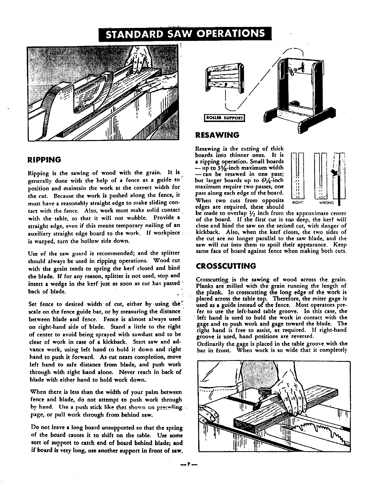
RESAWING
RIPPING
Ripping is the sawing of wood with the grain. It is
generally done with the help of a fence as a guide to '_
position and maintain the work at the correct width for
the cut. Because the work is pushed along the fence, it
must have a reasonably straight edge to make sliding con-
tact with the fence. Also, work must make solid contact
with the table, so that it will not wobble. Provide a
straight edge, even if this means temporary nailing of an
auxiliary straight edge board to the work. If workpiece
is warped, turn the hollow side down.
Use of the saw guard is recommended; and the splitter
should always be used in ripping operations. Wood cut
with the grain tends to spring the kerr closed and bind
the blade. If for any reason, splitter is not used, stop and
insert a wedge in the kerr just as soon as cut ha_ passed'
back of blade.
? !
Set fence to desired width of cut, either by.using the'.
scale on the fence guide bar, or by measuring the distance
between blade and fence. Fence is almost always used:
on rlght-hand side of blade. Stand a little to the right
of center to avoid being sprayed with sawdust and to be
clear of work in case of a kickback. Start saw and ad-
vance work, using left hand tO hold it down and right
hand to push it forward. As cut nears completion, move
left hand to safe distance from blade, and push work
through with right hand alone. Never reach in back of
blade with either hand to hold work down.
When there is less than the width of your palm between
fence and blade, do not attempt to push work through
by hand. Use a push stick like that shown on preceding ,_
page, or pull work through from behind saw.
Do not leave a long board unsupported so that the spring
of the board causes it to shift on the table. Use some
sort of support to catch end of board behind blade; and
if board is very long, use another support in front of saw,
Resawing is the cutting of thick
b°ards int° thlnoer ones' It is _ iN__
HN''7
-- up to 5_/_-inch maximum width I ..
--can be resawed in one pass;
but larger boards up to 6l_.ihch
maximum require twopasses, one
pass along each edge of the board.
When two cuts from opposite R_O_T
edges are required, these should
be made to overlap V2 inch from the approximate center
of the board. If the first cut is too deep, the kerf will
close and bind the saw on the second cut, with danger of
kickback. Also, when the kerf closes, the two sides of
the cut are no longer parallel to the saw blade, and the
saw will cut into them to spoil their appearance. Keep
same face of board against fence when making both cuts.
CROSSCUTTING
Crosscutting is the sawing of wood across the grain.
Planks are milled with the grain running the length of
the plank. In crosscutting the long edge of the work is
placed across the table top. Therefore, the miter gage is
used as a guide instead of the fence. Most operators pre-
fer to use the left-hand table groove. In this case, the
: left hand is used to hold the work in contact with the
gage and to push work and gage toward the blade. The
right hand is free to assist, as required. If right-hand
groove is used, hand positions are reversed.
Ordinarily the gage is placed in the table groove with the
bar in front. When work is so wide that it completely
/
CROSSCUTTING -- Continued
covers table in front of blade_ th_ ;_'';
gage should be reversed.
crosscutting is done with the miter
gage set at "90" (at a right angle
to the slide and groove). The
splitter need not be removed, but
is not needed for this operation.
Start the cut slowly and hold work
firmly to table to prevent kick-
back or chatter. (Loosely held
workpieces will sometimes vibrate
against table when crosscutting.
This tends to bind blade and dull
teeth.) An auxiliary wooden ex-
tension bolted to miter gage
greatly improves the gage _s a
support. If fitted with pin points
(phonograph needles are excel-
lent) or sandpaper, the extension
will help prevent side creep of
the work. If workpiece overhangs
table enough to sag at each end,
provide supports the same as in
ripping operations. The stop rod
on the miter gage, or a stop block
fastened to the extension, is used
to fix position of left-hand edge
of work for measuring length of
piece to be cut off.
BEVEL AND MITER CUTS
Bevels from 1° to 45 ° are cut by tilting the saw blade.
Operations are the same as for ripping or crosscutting--
but work should be extra well supported to prevent creep.
bikers ate crosscuts at an angle
to the edge of the workpiece. The _-_,'1
miter gage is set at the required' "'_ _;angle to make the cut. Here also, __
precautions must be taken to pre-
vent creep.
USE OF THE DADO HEAD
The dado saw or head, as it is.
called, is a special set of blades
for cutting grooves and dados on
the circular saw. Dado heads can
he purchased at any Sears Retail
Store or Mail Order House. The.
head consists of two solid, stiff
outside blades, and a number of
inside chipper blades. Tile outside
blades are 1/8-inch thick; there is
one 1/4-inch, two 1/8-ioch, and
one 1/16-ioch chipper blades.
With these blades, grooves of 1/8
inch, I/4 inch, and additional
widths increased in steps of 1/16
inch up to a maximum of 13/16-
__OUtSIDt _,_w , I 64 ¸'
% _. €Niece R
O41ppt ps AmA_'GED
Source Form 9763
inch wide can be cut. Outside blades can be used alone,
chippers cannot.
When using a full set of dado blades, it is permissible
to eliminate the loose collar (Key No. 9, fig. I) if the
operator so desires. Or the width of the dado can be
reduced while using the loose collar and two or more
passes can be made with the work to obtain the desir-
ed width of cut.
A dado insert (Key No. 100, fig. 1) must be used to re-
place the standard table insert. When using a full 13/16
mch dado set the arbor cannot be tilted to 45 ° without
touching the insert. Do not operate in this position.
Whenever two or more chippers are used, stagger the
swaged ends as evenly as possible around the circumfer-
ence. Fractional adjustments in thickness of the head
can be made b)' using paper washers between the out-
side blades and chippers.
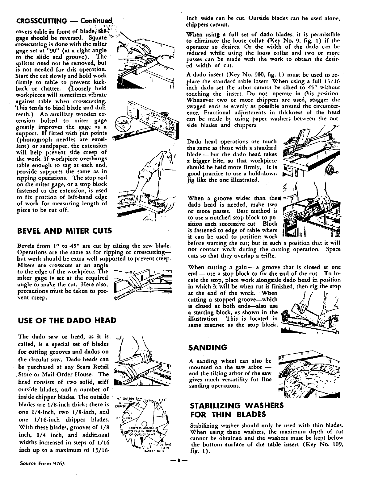
Dado head operations are much
the same as those with a standard
blade--but the dado head takes
a bigger bite, so that workpiece
should be held more firmly. It is
good practice to use a hold-down
jig like the one illustrated.
When a groove wider than the1
dado head is needed, make two
or more passes. Best method is
to use a notched stop block to po-
sition each successive cut. Block
is fastened to edge of table where
it can be used to position work
before starting the cut; but in such a position that it will
not contact work during the cutting operation. Space
cuts so that they overlap a trifle.
When cutting a gain--a groove that is closed at one
end-- use a stop block to fix the end of the cut. To lo-
cate the stop, place work alongside dado head in position
in which it will be when cut is finished, then rig the stop
at the end of the work. When
cutting a stopped groove--which
is closed at both ends--also use
a starting block, as shown in the
illustration. This is located in
same manner as the stop block.
SANDING
A sanding wheel can also be
mounted on the saw arbor --
and the tilting arbor of the saw
gives much versatility for fine
sanding operations.
STABILIZING WASHERS
FOR THIN BLADES
Stabilizing washer should only be used with thin blades.
When using these washers, the maximum depth of cut
cannot be obtained and the washers must be kept below
the bottom surface of the table insert (Key No. 109,
fig. l ).