Loading ...
Loading ...
Loading ...
InstructionsIorAssemblingandOperatingYourSaw
A LE F H G M
T V D J
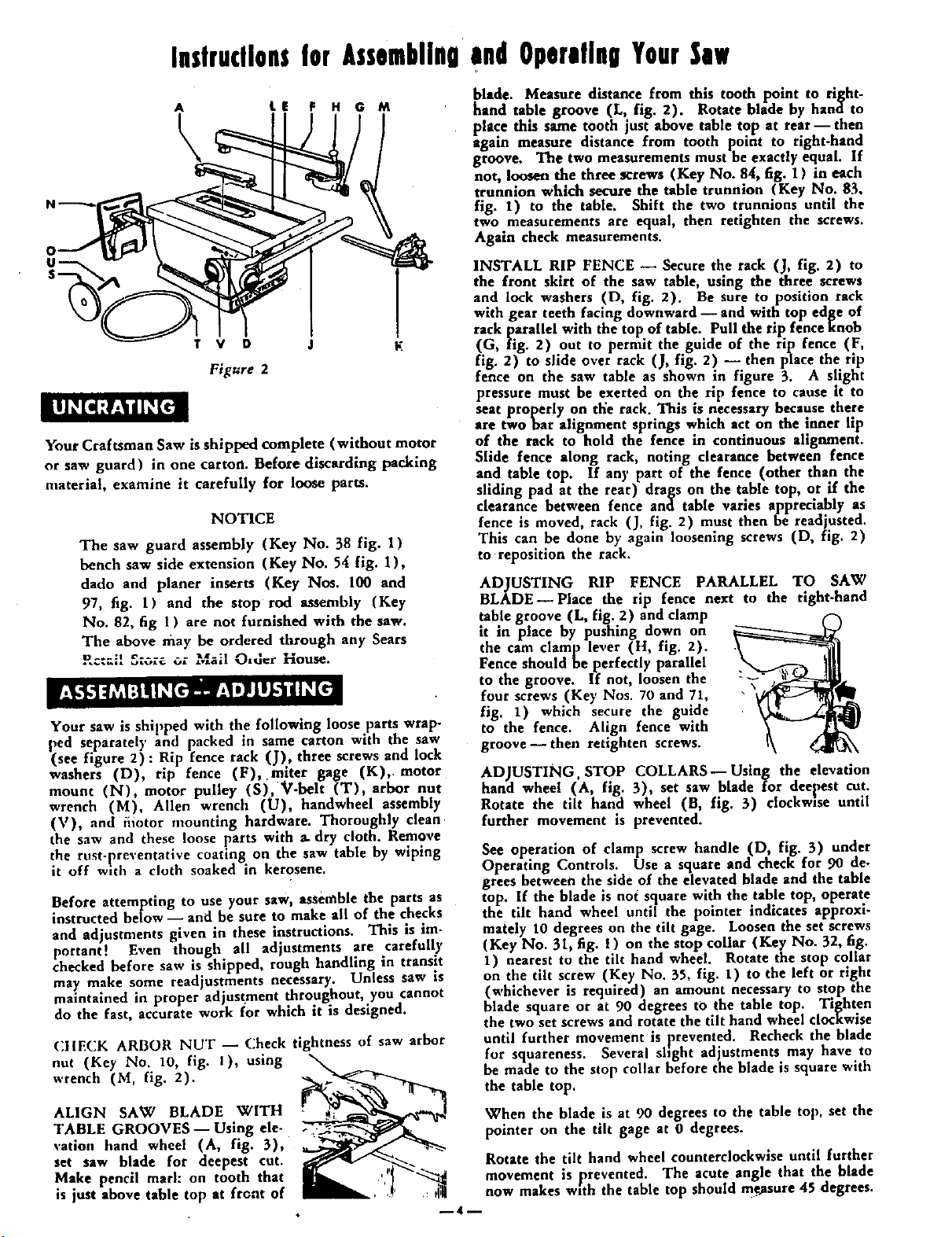
Fi[ure 2
Your Craftsman Saw is shipped complete (without motor
or saw guard) in one carton. Before discarding packing
nmterial, examine it carefully for loose parts.
NOTICE
The saw guard assembly (Key No. 38 fig. 1)
bench saw side extension (Key No. 54 fig. 1),
dado and planer inserts (Key Nos. 100 and
97, fig. 1) and the stop rod assembly (Key
No. 82, fig 1 ) are not furnished with the saw.
The above may be ordered through any Sears
!_c:ail S_c,re or Mail O,d_r House.
Your saw is shipped with the following loose parts wrap-
ped separately and packed in same carton with the saw
(see figure 2): Rip fence rack (J), three screws and lock
washers (D) rip fence (F), mlter gage (K),. motor
mount (N), motor pulley (S), V-belt (T), arbor nut
wrench (M), Allen wrench (U), handwheel assembly
('st), and fiiotor mounting hardware. Thoroughly clean
the saw and these loose parts with a. dry cloth. Remove
the rust-preventative coating on the saw table by wiping
it off with a cloth soaked in kerosene.
Before attempting to use your saw, assemble the parts as
instructed below-- and be sure to make all of the checks
and adjustments given in these instructions. This is im-
portant! Even though all adjustments are carefully
checked before saw is shipped, rough handling in transit
may make some readjustments necessary. Unless saw is
maintained in proper adjustment throughout, you cannot
do the fast, accurate work for which it is designed.
CIIECK ARBOR NUT -- Check tightness of saw arbor
out (Key No. 10, fig. 1), using _-_
wrench (M, fig. 2).
ALIGN SAW BLADE wITH
TABLE GROOVES--Using ele-
vation hand wheel (A, fig. 3),
set saw blade for deepest cut.
Make pencil marl: on tooth that
is just above table top at front of
blade. Measure distance from this tooth point to right-
hand table groove (L, fig. 2). Rotate blade by hana to
place thus same tooth just above table top at rear- then
a-gain measure distance from tooth point to rlght-hand
groove. The two measurements must he exactly equal. If
not, loosen the three screws (Key No. 84, fig. 1) in each
trunnion which secure the table trunnion (Key No. 83,
fig. I) to the table. Shift the two trunnions until the
two measurements are equal, then retighten the screws.
Again check measurements.
INSTALL RIP FENCE -- Secure the rack (J, fig. 2) to
the front skirt of the saw table, using the three screws
and lock washers (D, fig. 2). Be sure to position rack
with gear teeth facing downward -- and with top edge of
rack parallel with the top of table. Pull the rip fence knob
(G, fig. 2) out to permit the guide of the rip fence (F,
fig. 2) to slide over rack (J, fig. 2) -- then place the rip
fence on the saw table as shown in figure 3. A slight
pressure must be exerted on the rip fence to cause it to
seat properly on the rack. This is necessary because there
are two bar alignment springs which act on the inner lip
of the rack to hold the fence in continuous alignment.
Slide fence along rack, noting clearance between fence
and table top. If an)' part of the fence (other than the
sliding pad at the rear) drags on the table top, or if the
clearance between fence and table vanes apprectably as
fence is moved, rack (J, fig. 2) must then be readjusted.
This can be done by again loosening screws (D, fig. 2)
to reposition the rack.
ADJUSTING RIP FENCE PARALLEL TO SAW
BLADE--Place the tip fence next to the right-hand
table groove (L, fig. 2) and clamp
tt m place by pushing down on
the cam clamp le, er (H, fig. 2).
Fence should be perfectly parallel
to the groove. If not, loosen the -'_
four screws (Key Nos. 70 and 71,
fig. 1) which secure the guide
to the fence. Align fence with
groove--then retighten screws.
ADJUSTING. STOP COLLARS--Using the elevation
hand wheel (A, fig. 3), set saw blade for deepest cut.
Rotate the tilt hand wheel (B, fig. 3) clockwise until
further movement is prevented.
See operation of clamp screw handle (D, fig. 3) under
Operating Controls. Use a square and check for 90 de-
grees between the side of the elevated blade and the table
top. If the blade is not square with the table top, operate
the tilt hand wheel until the pointer indicates approxi-
mately 10 degrees on the tilt gage. Loosen the set screws
(Key No. 31, fig. l ) on the stop collar (Key No. 32, fig.
1) nearest to the tilt hand wheel. Rotate the stop collar
on the tilt screw (Key No. 55, fig. 1) to the left or right
(whichever is required) an amount necessary to stop the
blade square or at 90 degrees to the table top. Tighten
the two set screws and rotate the tilt hand wheel clocxwise
until further movement is prevented. Recheck the blade
for squareness. Several shght adjustments may have to
be made to the stop collar before the blade is square with
the table top.
When the blade is at 90 degrees to the table top, set the
pointer on the tilt gage at 0 degrees.
Rotate the tilt hand wheel counterclockwise until further
movement is _preveoted. The acute angle that the blade
now makes with the tab e top should mgasure 45 degrees.
--4--
Loading ...
Loading ...
Loading ...