Use & Care Guide
®
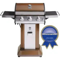
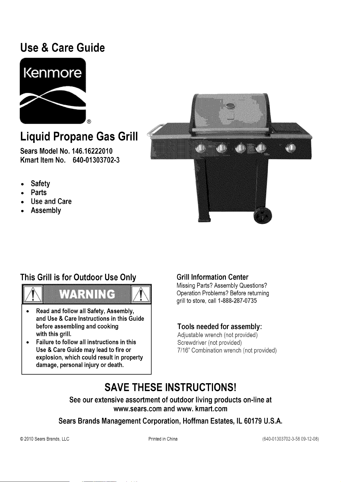
Liquid Propane Gas Grill
SearsModelNo. 146.16222010
KmartItemNo. 640-01303702-3
• Safety
• Parts
• Useand Care
• Assembly
ThisGrillis forOutdoorUseOnly
• Read and follow all Safety, Assembly,
and Use & Care Instructions in this Guide
before assembling and cooking
with this grill.
• Failure to follow all instructions in this
Use & Care Guide may lead to fire or
explosion, which could result in property
damage, personal injury or death.
Grill InformationCenter
Missing Parts? Assembly Questions?
Operation Problems? Before returning
grill to store, call 1-888-287-0735
Tools needed for assembly:
Adjustable wrench (not provided)
Screwdriver (not provided)
7/16" Combination wrench (not provided)
SAVETHESE INSTRUCTIONS!
See our extensive assortment of outdoor living products on-line at
www.sears.comand www. kmart.com
SearsBrandsManagementCorporation,HoffmanEstates,IL 60179U.S.A.
© 2010SearsBrands,LLC Printedin China (640°01303702°3°5809o12o08)
If you smellgas:
1. Shut off gasto the appliance.
2. Extinguishanyopenflame.
3. Open lid.
4. Ifodor continues,keepawayfrom the
applianceand immediatelycallyour gas
supplieror your fire department.
1. Donotstore or usegasolineor other
flammableliquidsorvapors in the vicinityof
this or anyother appliance.
2. An LP cylindernot connectedfor useshallnot
bestoredinthe vicinityof this or any other
appliance.
Call Grill Service Center For Help And Parts
If you have questions or need assistance during assembly,
please call 1-888-287-0735. You will be speaking to a
representative of the grill manufacturer and not a Sears
employee. To order new parts call Sears at 1-800-4-MY-HOME@.
Product Record
IMPORTANT:Fillouttheproductrecordinformationbelow.
Model Number
Serial Number
Seeratinglabelon grillfor serialnumber.
Date Purchased
CALIFORNIA PROPOSITION 65
1. Combustion by-products produced when using
this product contain chemicals known to the State of
California to cause cancer, birth defects, and other
reproductive harm.
2. This productcontainschemicals,includinglead
and lead compounds,known to the State of
California to cause cancer, birth defects or other
reproductiveharm.
Wash_ur hands after handlingthis product.
Installation Safety Precautions
• Use grill, as purchased, only with LP (propane) gas and the
regulator/valve assembly supplied. A conversion kit must be
purchased for use with natural gas.
• Grill installation must conform with local codes, or in their
absence of local codes, with either the National Fuel Gas
Code, ANSI Z223.1/NFPA 54, Natural Gas and Propane
Installation Code, CSA B149.1, or Propane Storage and
Handling Code, B149.2, or the Standard for Recreationa
Vehicles, ANSI A 119.2/NFPA 1192, and CSA Z240 RV Series
Recreational Vehicle Code, as applicable.
• All electrical accessories (such as rotisserie) must be
electrically grounded in accordance with local codes, or
National Electrical Code, ANSI / NFPA 70 or Canadian
Electrical Code, CSA C22.1. Keep any electrical cords and/or
fuel supply hoses away from any hot surfaces.
• This grill is safety certified for use in the United States and/or
Canada only. Do not modify for use in any other location.
Modification will result in a safety hazard.
Safety Symbols
The symbols and boxes shown below explain what each heading
means. Read and follow all of the messages found throughout
the manual.
BANGER: Indicates an imminently hazardous situation
which, if not avoided, will result in death or serious injury.
.................CAUTION
For residential use only. Do not use for commercial
cooking.
2.640-01303702-3-58
CAUTION: Indicates a potentially hazardous situation or
unsafe practice which, if not avoided, may result in minor
or moderate injury.
2
For Your Safety...
Grill Service Center...
Product Record Information ...
Safety Symbols...
Installation Safety Precautions ...
Kenmore Grill Warranty...
Use and Care...
Parts List...
Parts Diagram.
Assembly...
Troubleshooting ..
2
2
2
2
3
.4-10
...11
..12
13-22
23-25
Sears installation Service
For Sears professional installation of home appliances, garage
door openers, water heaters, and other major home items, in the
U.S.A. call 1-800-4-MY-HOME@
Kenmore FullWarranty on the Grill
Ifthis grill fails due to a defect in material or workmanship
within one year from the date of purchase, call 1-800-4-MY
HOME@to arrange for free repair (or replacement if repair
proves impossible).
Limited Warranty on Burners
For five years from the date of purchase, any burner that
rusts through will be replaced free of charge. After the first
year from the date of purchase, you pay for labor if you wish
to have it installed.
All warranty coverage excludes ignitor batteries and grill part
paint loss, discoloration or rusting, which are either
expendable parts that can wear out from normal use within
the warranty period, or are conditions that can be the result
of normal use, accident or improper maintenance.
AIIwarranty coverage is void if this grill is ever used for
commercial or rental purposes.
AIIwarranty coverage applies only if this grill is used in the
United States.
This warranty gives you specific legal rights, and you may
also have other rights which vary from state to state.
Sears, Roebuck and Co., Hoffman Estates, IL 60179
640-01303702-3-58,3
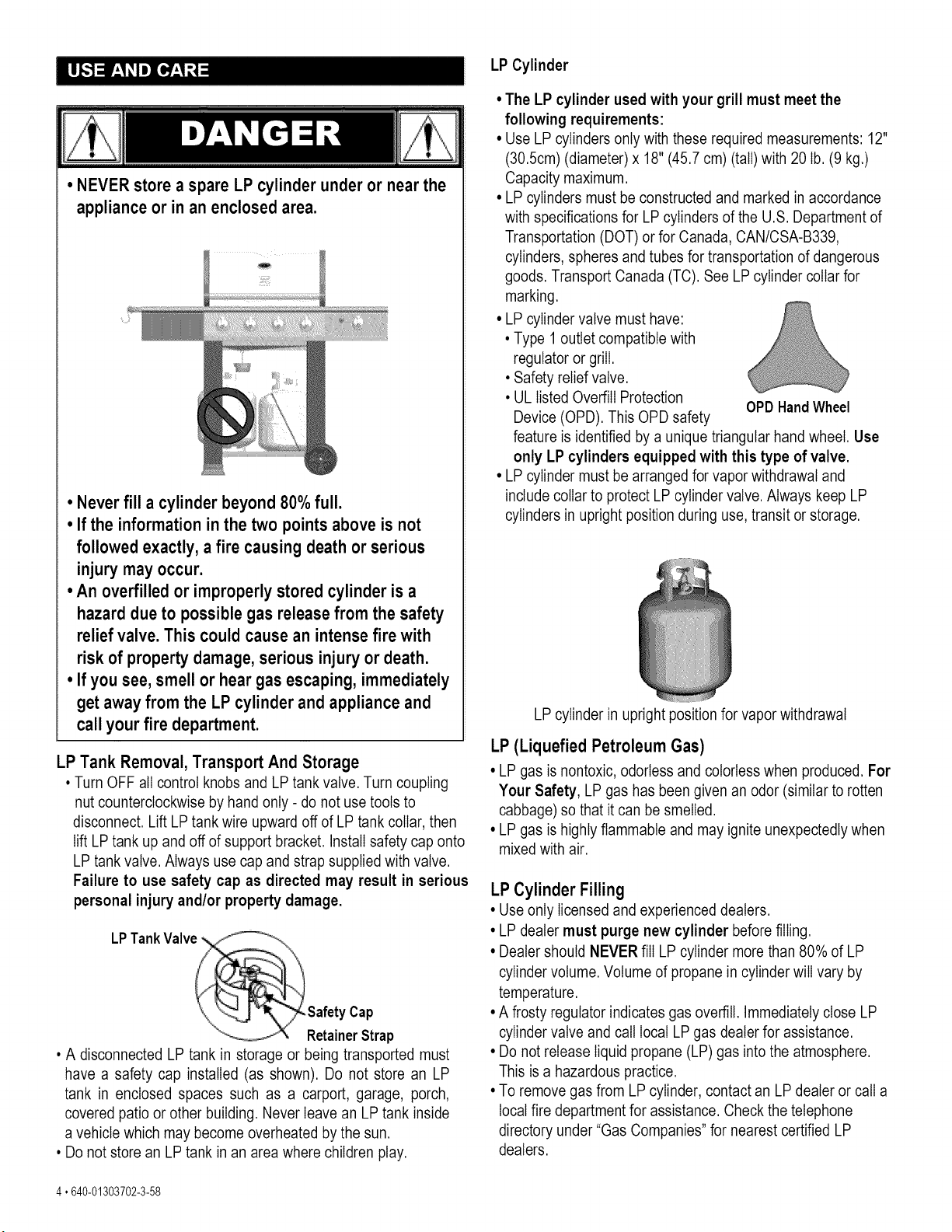
• NEVER store a spare LP cylinder under or near the
appliance or in an enclosed area.
• Never fill a cylinder beyond 80% full.
• If the informationin the two points above is not
followed exactly, a fire causing death or serious
injury may occur.
° An overfilled or improperly stored cylinder is a
hazard due to possible gas release from the safety
relief valve. This could cause an intensefire with
risk of property damage, serious injury or death.
° If you see, smell or hear gas escaping, immediately
get away from the LP cylinder and appliance and
call your fire department.
LP Tank Removal, Transport And Storage
• Turn OFF all control knobs and LP tank valve. Turn coupling
nut counterclockwise by hand only - do not use tools to
disconnect. Lift LP tank wire upward off of LP tank collar, then
lift LP tank up and off of support bracket. Install safety cap onto
LP tank valve. Always use cap and strap supplied with valve.
Failure to use safety cap as directed may result in serious
personal injury and/or property damage.
• A disconnected LP tank in storage or being transported must
have a safety cap installed (as shown). Do not store an LP
tank in enclosed spaces such as a carport, garage, porch,
covered patio or other building. Never leave an LP tank inside
a vehicle which may become overheated by the sun.
• Do not store an LP tank in an area where children play.
LP Cylinder
• The LP cylinder used with your grill must meet the
following requirements:
• Use LP cylinders only with these required measurements: 12"
(30.5cm) (diameter) x 18" (45.7 cm) (tall) with 20 Ib. (9 kg.)
Capacity maximum.
• LP cylinders must be constructed and marked in accordance
with specifications for LP cylinders of the U.S. Department of
Transportation (DOT) or for Canada, CAN/CSA-B339,
cylinders, spheres and tubes for transportation of dangerous
goods. Transport Canada (TC). See LP cylinder collar for
marking.
• LP cylinder valve must have:
• Type 1 outlet compatible with
regulator or grill.
• Safety relief valve.
• UL listed Overfill Protection
OPDHandWheel
Device (OPD). This OPD safety
feature is identified by a unique triangular hand wheel. Use
only LP cylinders equipped with this type of valve.
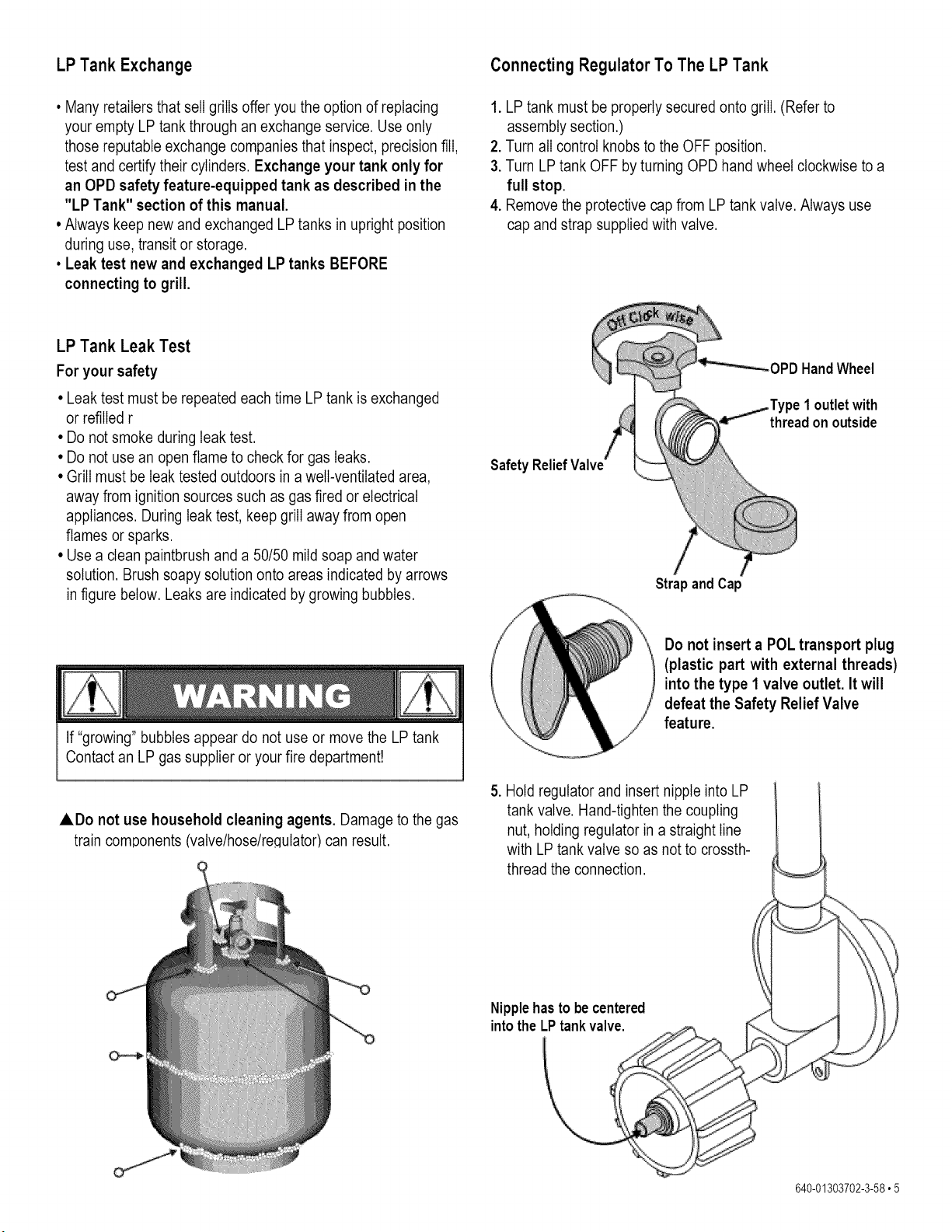
• LP cylinder must be arranged for vapor withdrawal and
include collar to protect LP cylinder valve. Always keep LP
cylinders in upright position during use, transit or storage.
LP cylinder in upright position for vapor withdrawal
LP (Liquefied Petroleum Gas)
• LP gas is nontoxic, odorless and colorless when produced. For
Your Safety, LP gas has been given an odor (similar to rotten
cabbage) so that it can be smelled.
• LP gas is highly flammable and may ignite unexpectedly when
mixed with air.
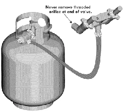
LP Cylinder Filling
• Use only Iicensed and experienced dealers.
• LP dealer must purge new cylinder before filling.
• Dealer should NEVER fill LP cylinder more than 80% of LP
cylinder volume. Volume of propane in cylinder will vary by
temperature.
• A frosty regulator indicates gas overfill. Immediately close LP
cylinder valve and call local LP gas dealer for assistance.
• Do not release liquid propane (LP) gas into the atmosphere.
This is a hazardous practice.
• To remove gas from LP cylinder, contact an LP dealer or call a
local fire department for assistance. Check the telephone
directory under "Gas Companies" for nearest certified LP
dealers.
4 °640-01303702-3-58
LP Tank Exchange Connecting Regulator To The LP Tank
• Many retailers that sell grills offer you the option of replacing
your empty LP tank through an exchange service. Use only
those reputable exchange companies that inspect, precision fill,
test and certify their cylinders. Exchange your tank only for
an OPD safety feature-equipped tank as described in the
"LP Tank" section of this manual.
• Always keep new and exchanged LP tanks in upright position
during use, transit or storage.
• Leak test new and exchanged LP tanks BEFORE
connecting to grill.
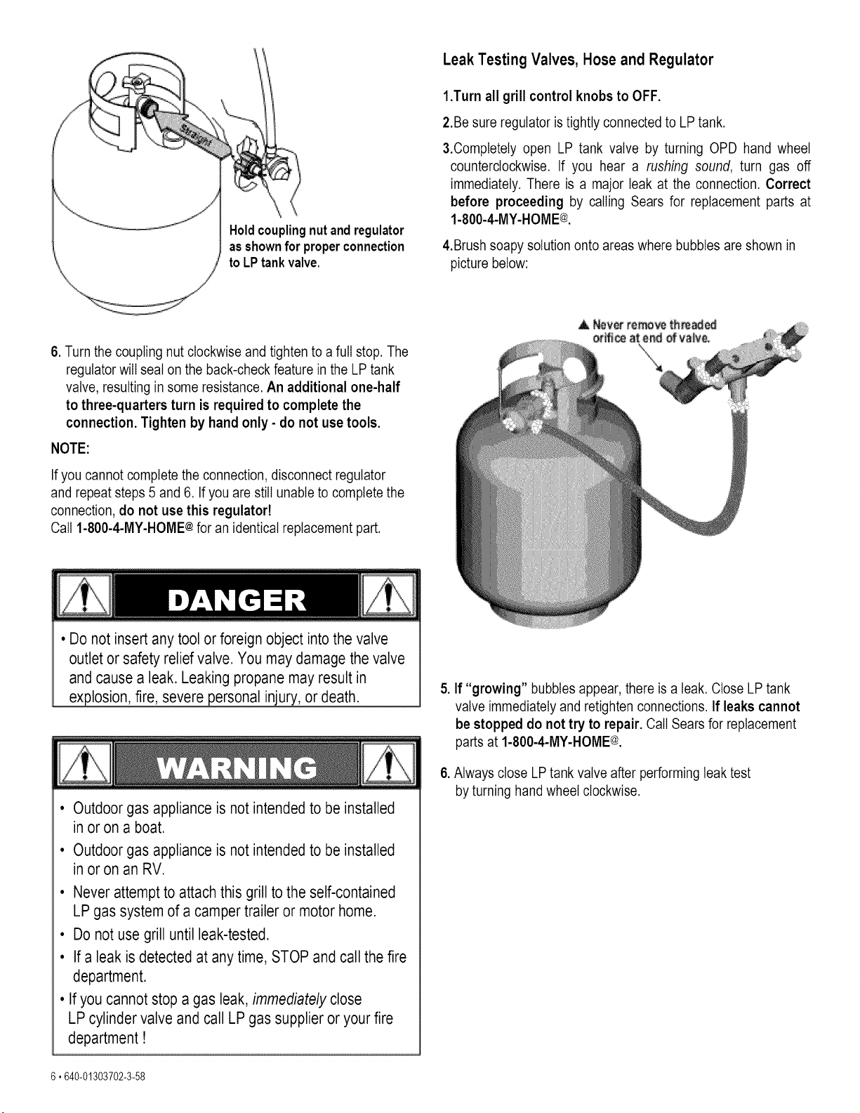
1. LP tank must be properly secured onto grill. (Refer to
assembly section.)
2. Turn all control knobs to the OFF position.
3. Turn LP tank OFF by turning OPD hand wheel clockwise to a
full stop.
4. Remove the protective cap from LP tank valve. Always use
cap and strap supplied with valve.
LP Tank Leak Test
For your safety
• Leak test must be repeated each time LP tank is exchanged
or refilled r
• Do not smoke during leak test.
• Do not use an open flame to check for gas leaks.
• Grill must be leak tested outdoors in a well-ventilated area,
away from ignition sources such as gas fired or electrical
appliances. During leak test, keep grill away from open
flames or sparks.
• Use a clean paintbrush and a 50/50 mild soap and water
solution. Brush soapy solution onto areas indicated by arrows
in figure below. Leaks are indicated by growing bubbles.
Safety Relief
/ /
Strap and Cap
HandWheel
1outletwith
threadon outside
If "growing" bubbles appear do not use or move the LP tank
Contact an LP gas supplier or your fire department!
ADo not use household cleaning agents. Damage to the gas
train components tvatve/hose/re¢lutator)can result.
Do not insert a POL transport plug
(plastic part with external threads)
into the type 1 valve outlet. It will
defeat the Safety Relief Valve
feature.
5. Hold regulator and insert nipple into LP
tank valve. Hand-tighten the coupling
nut, holding regulator in a straight line
with LP tank valve so as not to crossth-
thread the connection.
Nipplehas to be centered
into the LPtank valve.
640-01303702-3-58,5
Holdcouplingnut andregulator
asshownfor properconnection
to LP tankvalve.
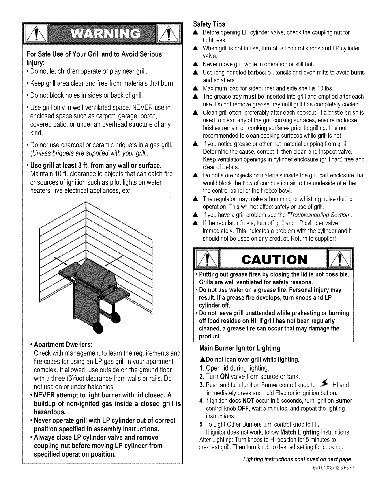
Leak Testing Valves, Hose and Regulator
1.Turn all grill control knobs to OFF.
2.Be sure regulator is tightly connected to LP tank.
&Completely open LP tank valve by turning OPD hand wheel
counterclockwise. If you hear a rushing sound, turn gas off
immediately. There is a major leak at the connection. Correct
before proceeding by calling Sears for replacement parts at
1-800-4-MY-HOME@.
4.Brushsoapy solution onto areas where bubbles are shown in
picture below:
6. Turn the coupling nut clockwise and tighten to a full stop. The
regulator will seat on the back-check feature in the LP tank
valve, resulting in some resistance. An additional one-half
to three-quarters turn is required to complete the
connection. Tighten by hand only - do not use tools.
NOTE:
If you cannot complete the connection, disconnect regulator
and repeat steps 5 and 6. If you are still unable to complete the
connection, do not use this regulatod
Call 1-800-4-MY-HOME¢ for an identical replacement part.
• Do not insert any tool or foreign object into the valve
outlet or safety relief valve. You may damage the valve
and cause a leak. Leaking propane may result in
explosion, fire, severe personal injury, or death.
• Outdoor gas appliance is not intended to be installed
in or on a boat.
• Outdoor gas appliance is not intended to be installed
in or on an RV.
• Never attempt to attach this grill to the self-contained
LP gas system of a camper trailer or motor home.
• Do not use grill until leak-tested.
• If a leak is detected at any time, STOP and call the fire
department.
• If you cannot stop a gas leak, immediately close
LP cylinder valve and call LP gas supplier or your fire
department!
6 °640-01303702-3-58
5. If "growing" bubbles appear, there is a leak. Close LP tank
valve immediately and retighten connections. If leaks cannot
be stopped do not try to repair. Call Sears for replacement
parts at 1-800-4-MY-HOME¢.
6. Always close LP tank valve after performing leak test
by turning hand wheel clockwise.
ForSafeUseof YourGrillandto AvoidSerious
Injury:
• Do notlet childrenoperateor playneargrill.
• Keep grill area clear and free from materials that burn.
• Do not block holes in sides or back of grill.
• Use grill only in well-ventilated space. NEVER use in
enclosed space such as carport, garage, porch,
covered patio, or under an overhead structure of any
kind.
• Do not use charcoal or ceramic briquets in a gas grill.
(Unless briquets are supplied withyour grill.)
• Use grill at least 3 ft. from any wall or surface.
Maintain 10 ft. clearance to objects that can catch fire
or sources of ignition such as pilot lights on water
heaters, live electrical appliances, etc.
• Apartment Dwellers:
Check with management to learn the requirements and
fire codes for using an LP gas grill in your apartment
complex. If allowed, use outside on the ground floor
with a three (3)foot clearance from walls or rails. Do
not use on or under balconies.
• NEVER attempt to light burner with lid closed. A
buildup of non-ignited gas inside a closed grill is
hazardous.
• Never operate grill with LP cylinder out of correct
position specified in assembly instructions.
• Always close LP cylinder valve and remove
coupling nut before moving LP cylinder from
specified operation position.
Safety Tips
• Before opening LP cylinder valve, check the coupling nut for
tightness.
• When grill is not in use, turn off all control knobs and LP cylinder
valve.
• Never move grill while in operation or still hot.
• Use long-handled barbecue utensils and oven mitts to avoid burns
and splatters.
• Maximum load for sideburner and side shelf is 10 Ibs.
• The grease tray must be inserted into grill and emptied after each
use. Do not remove grease tray until grill has completely cooled.
• Clean grill often, preferably after each cookout. If a bristle brush is
used to clean any of the grill cooking surfaces, ensure no loose
bristles remain on cooking surfaces prior to grilling. It is not
recommended to clean cooking surfaces while grill is hot.
• Ifyou notice grease or other hot material dripping from grill
Determine the cause, correct it, then clean and inspect valve,
Keep ventilation openings in cylinder enclosure (grill cart) free and
clear of debris.
• Do not store objects or materials inside the grill cart enclosure that
would block the flow of combustion air to the undeside of either
the control panel or the firebox bowl.
• The regulator may make a humming or whistling noise during
operation. This will not affect safety or use of grill.
• Ifyou have a grill problem see the "Troubleshooting Section".
• If the regulator frosts, turn off grill and LP cylinder valve
immediately. This indicates a problem with the cylinder and it
should not be used on any product. Return to supplier!
CAUTION
• Putting out grease fires by closing the lid is not possible.
Grills are well ventilated for safety reasons.
• Do not use water on a grease fire. Personal injury may
result. If a grease fire develops, turn knobs and LP
cylinder off.
• Do not leave grill unattended while preheating or burning
off food residue on HI. If grill has not been regularly
cleaned, a grease fire can occur that may damage the
product.
MainBurnerIgnitor Lighting
• Do not lean over grill while lighting.
1. Open lid during lighting.
2. Turn ON valve from source or tank.
3. Push and turn Ignition Burner control knob to HI and
immediately press and hold Electronic Ignition button.
4. If ignition does NOT occur in 5 seconds, turn Ignition Burner
control knob OFF, wait 5 minutes, and repeat the lighting
instructions.
5. To Light Other Burners turn control knob to HI.
If ignitor does not work, follow Match Lighting instructions.
After Lighting: Turn knobs to HI position for 5 minutes to
pre-heat grill. Then turn knob to desired setting for cooking.
Lightinginstructionscontinuedonnextpage.
640-01303702-3-58,7
If ignition does NOT occur in 5 seconds, turn the
burner controls OFF, wait 5 minutes and repeat the
lighting procedure. If the burner does not ignite with
The valve open, gas will contiune to flow out of the
burner and could accidently ignite with risk of injury
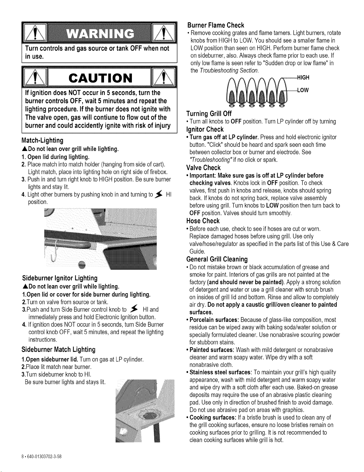
Match-Lighting
ADo not lean over grill while lighting.
1. Open lid during lighting.
2. Place match into match holder (hanging from side of cart).
Light match, place into lighting hole on right side of firebox.
3. Push in and turn right knob to HIGH position. Be sure burner
lights and stay lit.
4. Light other burners by pushing knob in and turning to _ HI
position.
Sideburner Ignitor Lighting
ADo not lean over grill while lighting.
1.Open lid or cover for side burner during lighting.
2.Turn on valve from source or tank.
&Push and turn Side Burner control knob to _ HI and
immediately press and hold Electronic Ignition button.
4. If ignition does NOT occur in 5 seconds, turn Side Burner
control knob OFF, wait 5 minutes, and repeat the lighting
instructions.
Sideburner Match Lighting
1.Open sideburner lid. Turn on gas at LP cylinder.
2.Place lit match near burner.
&Turn sideburner knob to HI.
Be sure burner lights and stays lit.
Burner Flame Check
• Remove cooking grates and flame tamers. Light burners, rotate
knobs from HIGH to LOW. You should see a smatler flame in
LOW position than seen on HIGH. Perform burner flame check
on sideburner, also. Always check flame prior to each use. If
only low flame is seen refer to "Sudden drop or low flame" in
the Troubleshooting Section.
Turning Grill Off
• Turn all knobs to OFF position. Turn LP cylinder off by turning
Ignitor Check
• Turn gas off at LP cylinder. Press and hold electronic ignitor
button. "Click" should be heard and spark seen each time
between collector box or burner and electrode. See
"Troubleshooting" if no click or spark.
Valve Check
• Important: Make sure gas is off at LP cylinder before
checking valves. Knobs lock in OFF position. To check
valves, first push in knobs and release, knobs should spring
back. If knobs do not spring back, replace valve assembly
before using grill. Turn knobs to LOW position then turn back to
OFF position. Valves should turn smoothly.
Hose Check
• Before each use, check to see if hoses are cut or worn.
Replace damaged hoses before using grill. Use only
valve/hose/regulator as specified in the parts list of this Use & Care
Guide.
General Grill Cleaning
• Do not mistake brown or black accumulation of grease and
smoke for paint. Interiors of gas grills are not painted at the
factory (and should never be painted). Apply a strong solution
of detergent and water or use a grill cleaner with scrub brush
on insides of grill lid and bottom. Rinse and allow to completely
air dry. Do not apply a caustic grill/oven cleaner to painted
surfaces.
• Porcelain surfaces: Because of glass-like composition, most
residue can be wiped away with baking soda/water solution or
specially formulated cleaner. Use nonabrasive scouring powder
for stubborn stains.
• Painted surfaces: Wash with mild detergent or nonabrasive
cleaner and warm soapy water. Wipe dry with a soft
nonabrasive cloth.
• Stainless steel surfaces: To maintain your grill's high quality
appearance, wash with mild detergent and warm soapy water
and wipe dry with a soft cloth after each use. Baked-on grease
deposits may require the use of an abrasive plastic cleaning
pad. Use only in direction of brushed finish to avoid damage.
Do not use abrasive pad on areas with graphics.
• Cooking surfaces: If a bristle brush is used to clean any of
the grill cooking surfaces, ensure no loose bristles remain on
cooking surfaces prior to grilling. It is not recommended to
clean cooking surfaces while grill is hot.
8.640-01303702-3-58
CAUTION
SPIDER ALERT!
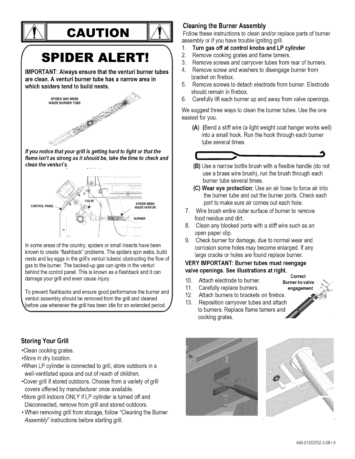
IMPORTANT: Always ensure that the venturi burner tubes
are clean. A venturi burner tube has a narrow area in
which spiders tend to build nests.
If younoticethatyour grill is getting hard to light or that the
flame isn't as strong as it should be, take the time to check and
clean the venturi's.
CONTROLPANEL
Insomeareasof the country,spidersor smallinsectshavebeen
knownto create"flashback"problems.Thespidersspinwebs,build
nestsand layeggsinthe grill'sventuritube(s)obstructingtheflow of
gasto the burner.The backed-upgas can ignitein theventuri
behindthecontrolpanel.Thisis knownas a flashbackand it can
damageyourgrilland evencauseinjury.
To preventflashbacksandensuregoodperformancethe burnerand
venturiassemblyshouldbe removedfrom the grilland cleaned
kLefo!eusewheneve!the g!i!!has beenid!e fo! an extended periodj
Cleaning the Burner Assembly
Follow these instructions to clean and/or replace parts of burner
assembly or if you have trouble igniting grill.
1. Turn gas off at control knobs and LP cylinder
2. Remove cooking grates and flame tamers.
3. Remove screws and carryover tubes from rear of burners.
4. Remove screw and washers to disengage burner from
b.racketon firebox.
5. Remove screws to detach electrode from burner. Electrode
should remain in firebox.
6. Carefully lift each burner up and away from valve openings.
We suggest three ways to clean the burner tubes. Use the one
easiest for you.
(A) (Bend a stiff wire (a light weight coat hanger works well)
into a small hook. Run the hook through each burner
tube several times.
(B) Use a narrow bottle brush with a flexible handle (do not
use a brass wire brush), run the brush through each
burner tube several times.
(C) Wear eye protection: Use an air hose to force air into
the burner tube and out the burner ports. Check each
port to make sure air comes out each hole.
7. Wire brush entire outer surface of burner to remove
food residue and dirt.
8. Clean any blocked ports with a stiff wire such as an
open paper clip.
9. Check burner for damage, due to normal wear and
corrosion some holes may become enlarged. If any
large cracks or holes are found replace burner.
VERY IMPORTANT: Burner tubes must reengage
valve openings. See illustrations at right.
Correct
10. Attach electrode to burner. Burner-to-valve
11. Carefully replace burners, engagement
12. Attach burners to brackets on firebox.
13. Reposition carryover tubes and attach
to burners. Replace flame tamers and
cooking grates.
Storing Your Grill
•Clean cooking grates.
•Store in dry location.
•When LP cylinder is connected to grill, store outdoors in a
well-ventilated space and out of reach of children.
•Cover grill if stored outdoors. Choose from a variety of grill
covers offered by manufacturer once available.
•Store grill indoors ONLY if LP cylinder is turned off and
Disconnected, remove from grill and stored outdoors.
• When removing grill from storage, follow "Cleaning the Burner
Assembly' instructions before starting grill.
640-01303702-3-58,9
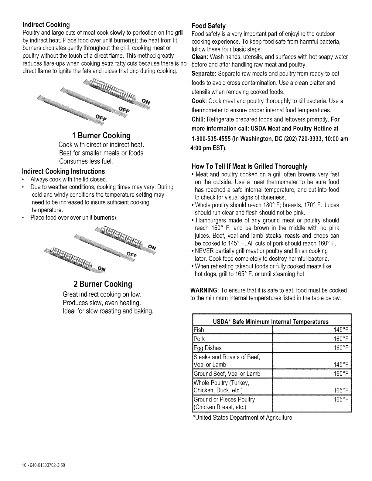
Indirect Cooking
Poultry and large cuts of meat cook slowly to perfection on the grill
by indirect heat. Place food over unlit burner(s); the heat from lit
burners circulates gently throughout the grill, cooking meat or
poultry without the touch of a direct flame. This method greatly
reduces flare-ups when cooking extra fatty cuts because there is no
direct flame to ignite the fats and juices that drip during cooking.
1 Burner Cooking
Cook with direct or indirect heat.
Best for smaller meals or foods
Consumes less fuel.
Indirect Cooking Instructions
• Always cook with the lid closed.
• Due to weather conditions, cooking times may vary. During
cold and windy conditions the temperature setting may
need to be increased to insure sufficient cooking
temperature.
• Place food over over unlit burner(s).
2 BurnerCooking
Great indirect cooking on low.
Produces slow, even heating.
Ideal for slow roasting and baking.
Food Safety
Food safety is a very important part of enjoying the outdoor
cooking experience. To keep food safe from harmful bacteria,
follow these four basic steps:
Clean: Wash hands, utensils, and surfaces with hot soapy water
before and after handling raw meat and poultry.
Separate: Separate raw meats and poultry from ready-to-eat
foods to avoid cross contamination. Use a clean platter and
utensils when removing cooked foods.
Cook: Cook meat and poultry thoroughly to kill bacteria. Use a
thermometer to ensure proper internal food temperatures.
Chill: Refrigerate prepared foods and leftovers promptly. For
more information call: USDA Meat and Poultry Hotline at
1-800-535-4555 (In Washington, DC (202) 720-3333, 10:00 am
4:00 pm EST).
How To Tell If Meat Is Grilled Thoroughly
• Meat and poultry cooked on a grill often browns very fast
on the outside. Use a meat thermometer to be sure food
has reached a safe internal temperature, and cut into food
to check for visual signs of aloneness.
• Whole poultry should reach 180° F; breasts, 170° F. Juices
should run clear and flesh should not be pink.
• Hamburgers made of any ground meat or poultry should
reach 160° F, and be brown in the middle with no pink
juices. Beef, veal and lamb steaks, roasts and chops can
be cooked to 145° F. All cuts of pork should reach 160° F.
• NEVER partially grill meat or poultry and finish cooking
later. Cook food completely to destroy harmful bacteria.
• When reheating takeout foods or fully cooked meats like
hot dogs, grill to 165° F, or until steaming hot.
WARNING: To ensure that it is safe to eat, food must be cooked
to the minimum internal temperatures listed in the table below.
USDA* Safe Minimum Internal Temperatures
Fish 145°F
Pork 160°F
Egg Dishes 160°F
Steaks and Roasts of Beef,
Veal or Lamb 145°F
O[ound Beel, a! 0[Lamb ................................................ ! 60 °E
Whole Poultry (Turkey,
Ground or Pieces Poultry 165°F
(Chicken Breast, etc.)
*United States Department of Agriculture
10 °640-01303702-3-58
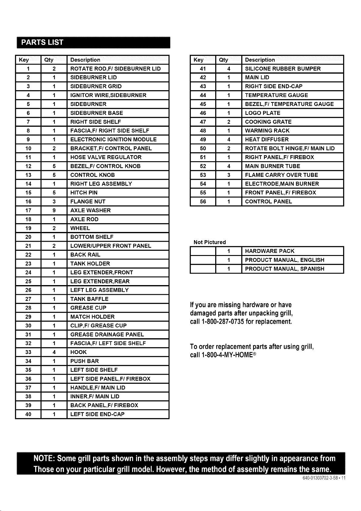
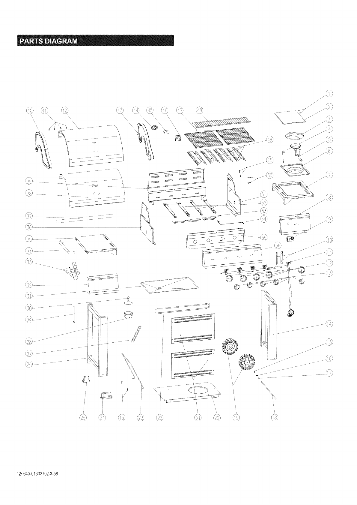
Key Qty Description ...........
1 2 ROTATE ROD,F/SIDEBURNER LID
2 1 SIDEBURNER LID
3 1 SIDEBURNER GRID
4 1 IGNITOR WlRE,SIDEBURNER
5 1 SIDEBURNER
6 1 SIDEBURNER BASE
7 1 RIGHT SIDE SHELF
8 1 FASCIA, F/RIGHT SIDE SHELF
9 1 ELECTRONIC IGNITION MODULE
10 2 BRACKET,F/CONTROL PANEL
11 1 HOSE VALVE REGULATOR
12 5 BEZEL,F/CONTROL KNOB
13 5 CONTROL KNOB
14 1 RIGHT LEG ASSEMBLY
15 5 HITCH PIN
16 3 FLANGE NUT
17 9 AXLE WASHER
18 1 AXLE ROD
19 2 WHEEL
20 1 BOTTOM SHELF
21 2 LOWER/UPPER FRONT PANEL
22 1 BACK RAIL
23 1 TANK HOLDER
24 1 LEG EXTENDER, FRONT
25 1 LEG EXTENDER, REAR
26 1 LEFT LEG ASSEMBLY
27 1 TANK BAFFLE
28 1 GREASE CUP
29 1 MATCH HOLDER
30 1 CLIP,F/GREASE CUP
31 1 GREASE DRAINAGE PANEL
32 1 FASCIA, F/LEFT SIDE SHELF
33 4 HOOK
34 1 PUSH BAR
35 1 LEFT SIDE SHELF
36 1 LEFT SIDE PANEL,F/FIREBOX
37 1 HANDLE,F/MAIN LID
38 1 INNER,F/MAIN LID
39 1 BACK PANEL,F/FIREBOX
40 1 LEFT SIDE END-CAP
Key Qty Description ...........
41 4 SILICONE RUBBER BUMPER
42 1 MAIN LID
43 1 RIGHT SIDE END-CAP
44 1 TEMPERATURE GAUGE
45 1 BEZEL,F/TEMPERATURE GAUGE
46 1 LOGO PLATE
47 2 COOKING GRATE
48 1 WARMING RACK
49 4 HEAT DIFFUSER
50 2 ROTATE BOLT HINGE,F/MAIN LID
51 1 RIGHT PANEL,F/FIREBOX
52 4 MAIN BURNER TUBE
53 3 FLAME CARRY OVER TUBE
54 1 ELECTRODE,MAIN BURNER
55 1 FRONT PANEL,F/FIREBOX
56 1 CONTROL PANEL
NotPictured
1 HARDWARE PACK
1 PRODUCT MANUAL, ENGLISH
1 PRODUCT MANUAL, SPANISH
If you are missing hardware or have
damaged parts after unpacking grill,
call 1-800-287-0735 for replacement.
To order replacement parts after using grill,
call 1-800-4-MY-HOME®
640-01303702-3-58o11
\
\
\
\
\
\
jf
i
J
_2"640-01303702.3.58
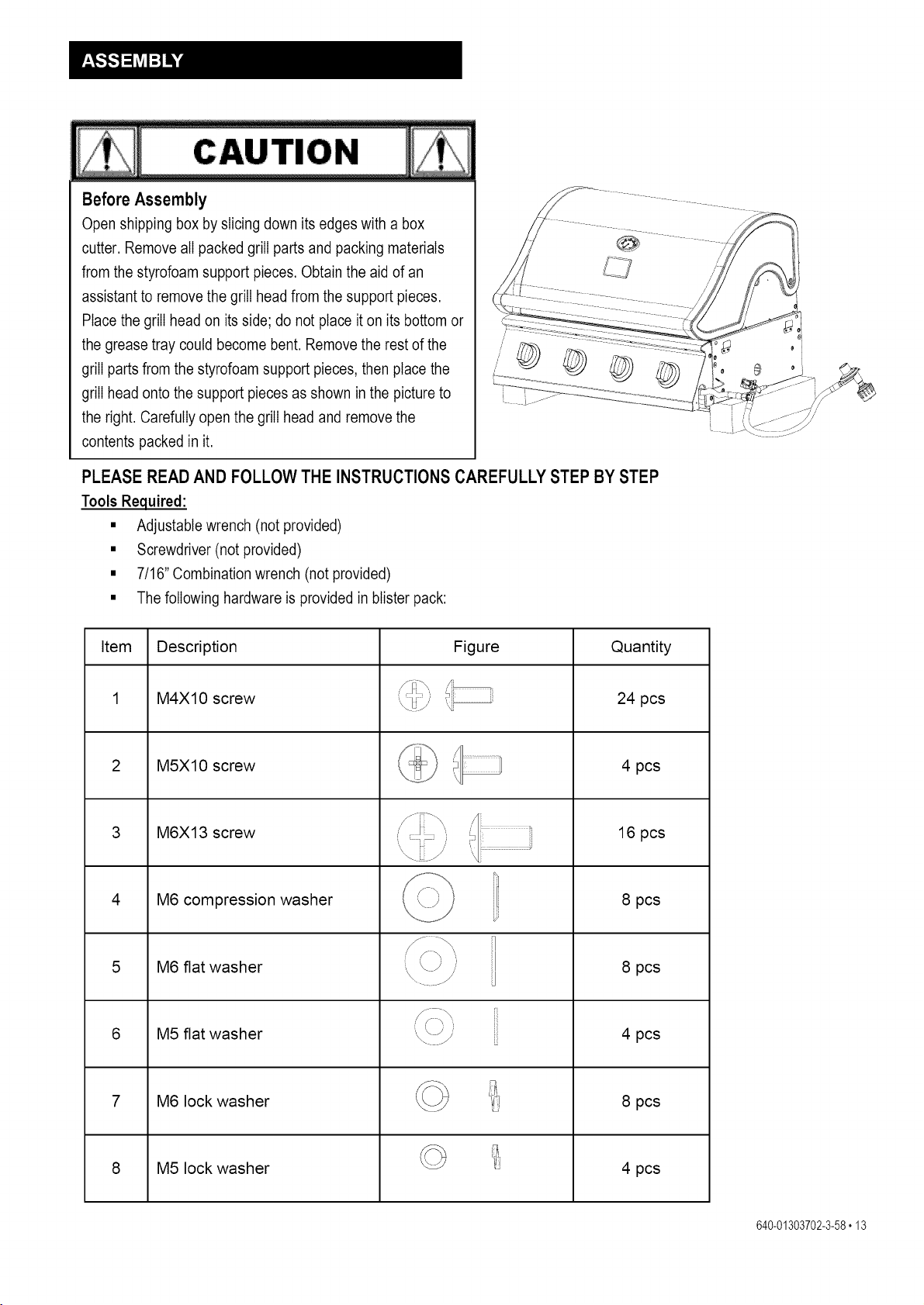
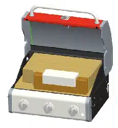
Before Assembly
Open shipping box by slicing down its edges with a box
cutter. Remove all packed grill parts and packing materials
from the styrofoam support pieces. Obtain the aid of an
assistant to remove the grill head from the support pieces.
Place the grill head on its side; do not place it on its bottom or
the grease tray could become bent. Remove the rest of the
grill parts from the styrofoam support pieces, then place the
grill head onto the support pieces as shown in the picture to
the right. Carefully open the grill head and remove the
contents packed in it.
PLEASE READ AND FOLLOW THE INSTRUCTIONS CAREFULLY STEP BY STEP
Tools Required:
• Adjustable wrench (not provided)
• Screwdriver (not provided)
• 7/16"Combination wrench (not provided)
• The following hardware is provided in blister pack:
Item Description
M4X10 screw
2 M5X10 screw
3 M6X13 screw
4
M6 compression washer
5 M6 flat washer
6 M5 flat washer
7 M6 lock washer
8 M5 lock washer
Figure
/J
"_\\
Quantity
24 pcs
4 pcs
16 pcs
8 pcs
8 pcs
4 pcs
8 pcs
4 pcs
640-01303702-3-58,13
/1
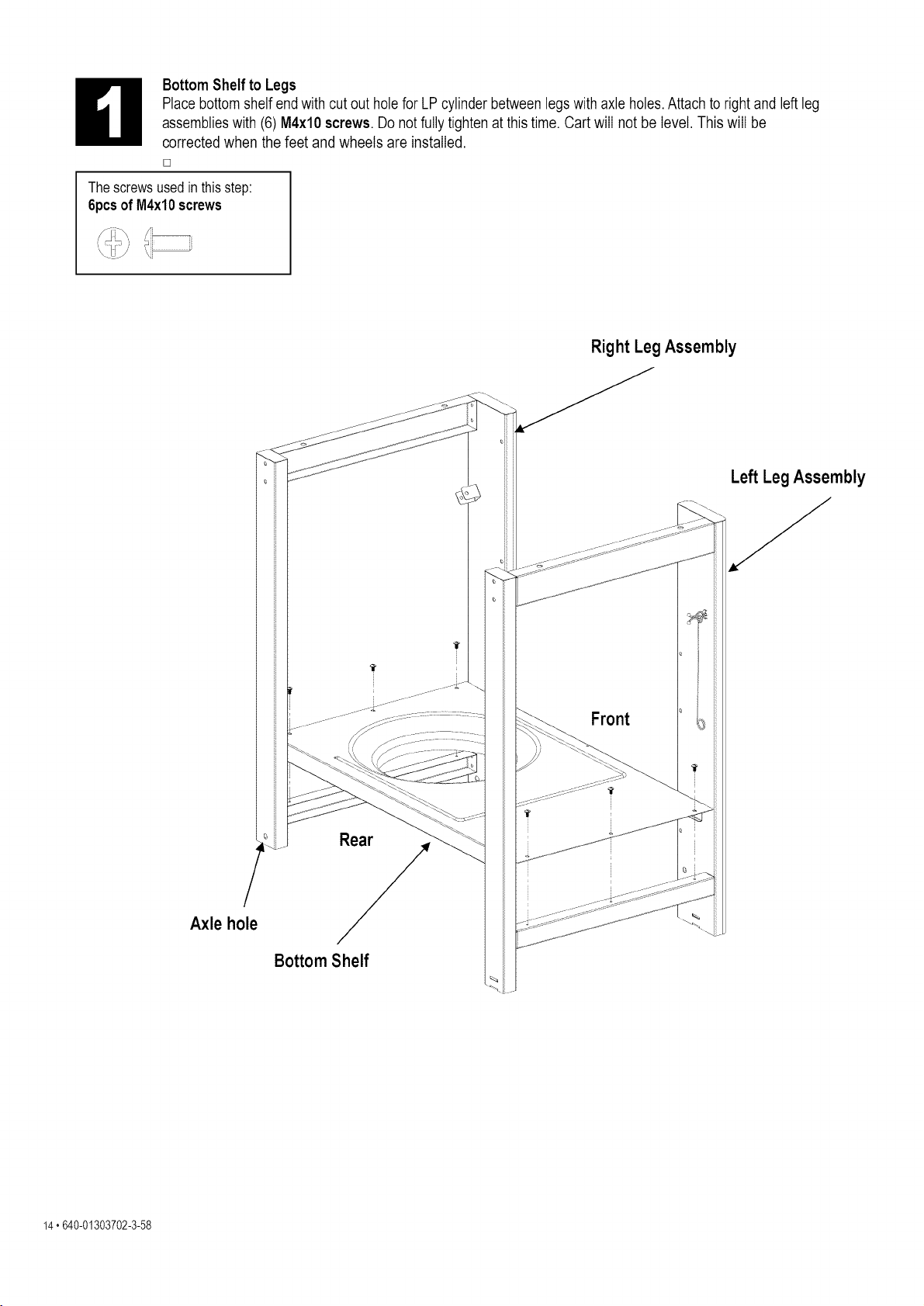
BottomShelf to Legs
Placebottom shelfend with cut out hole for LP cylinder betweenlegs with axle holes.Attach to right and left leg
assemblieswith (6)M4xl0 screws. Do notfully tighten at this time. Cart will not be level. This will be
corrected when the feet and wheels are installed.
[]
The screwsusedinthis step:
6pcsof M4xlOscrews
_i_i_ _i_ _i
Right Leg Assembly
Axle hole
Rear
f
BottomShelf
Front
Left Leg Assembly
f
14. 640-01303702-3-58
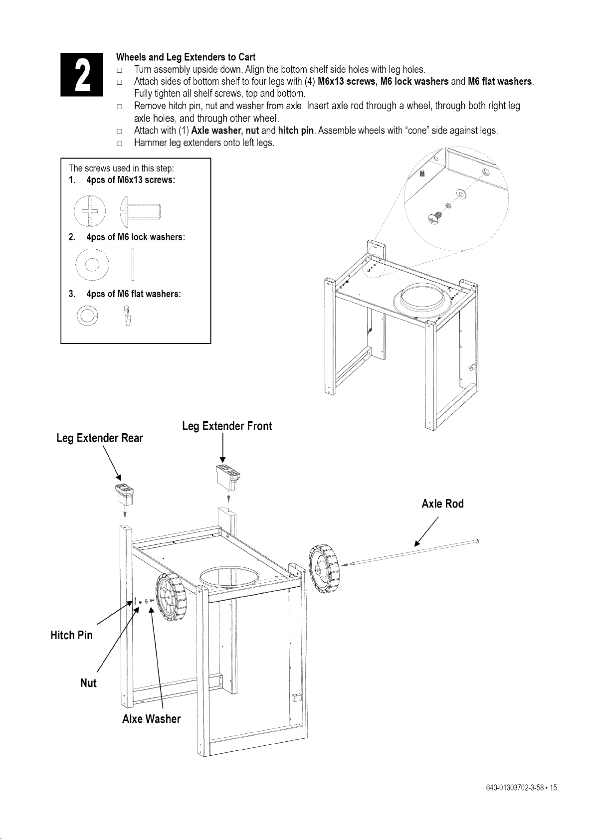
The screwsusedinthis step:
1. 4pcsofM6x13screws:
Wheels and Leg Extendersto Cart
[] Turn assembly upsidedown.Align the bottomshelfside holeswith leg holes.
[] Attach sides of bottom shelfto four legs with (4) M6x13 screws,M6 lock washers and M6flat washers.
Fullytighten all shelf screws,top and bottom.
[] Removehitchpin, nut andwasherfrom axle. Insert axle rod through a wheel, through both right leg
axle holes, and through other wheel.
[] Attach with (1) Axle washer, nut and hitch pin. Assemblewheels with "cone"side against legs.
[] Hammerlegextendersonto left legs.
/
2. 4pcs of M6Iockwashers:
3. 4pcsof M6flat washers:
Leg Extender Rear
\
Leg Extender Front
Axle Rod
/
Hitch Pin
Nut
Alxe Washer
640-01303702-3-58,15
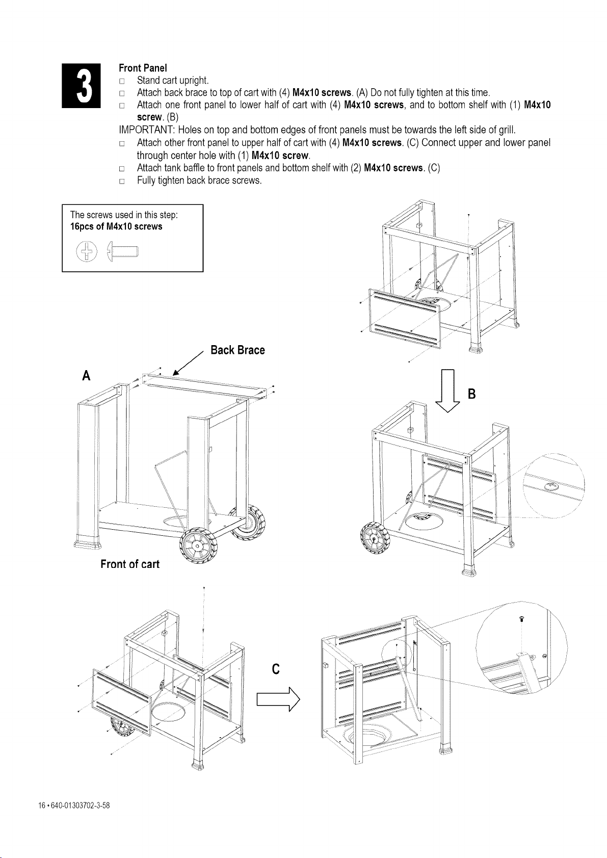
FrontPanel
[] Stand cart upright.
[] Attach back braceto top of cart with (4) M4xlO screws.(A) Do notfully tighten at this time.
[] Attach one front panel to lower half of cart with (4) M4xl0 screws, and to bottom shelf with (1) M4xl0
screw.(B)
IMPORTANT: Holes on top and bottom edges of front panels must be towards the left side of grill.
[] Attach other front panel to upperhalf of cart with (4) M4xl0 screws. (C) Connect upper and lower panel
through center hole with (1) M4xl0 screw.
[] Attach tank baffleto front panels and bottomshelf with (2) M4xl0 screws. (C)
[] Fully tightenback bracescrews.
The screwsusedinthis step:
16pcsof M4xl0 screws
_i(i_ _i _i
A
Back Brace
Front of cart
C
16,640-01303702-3-58
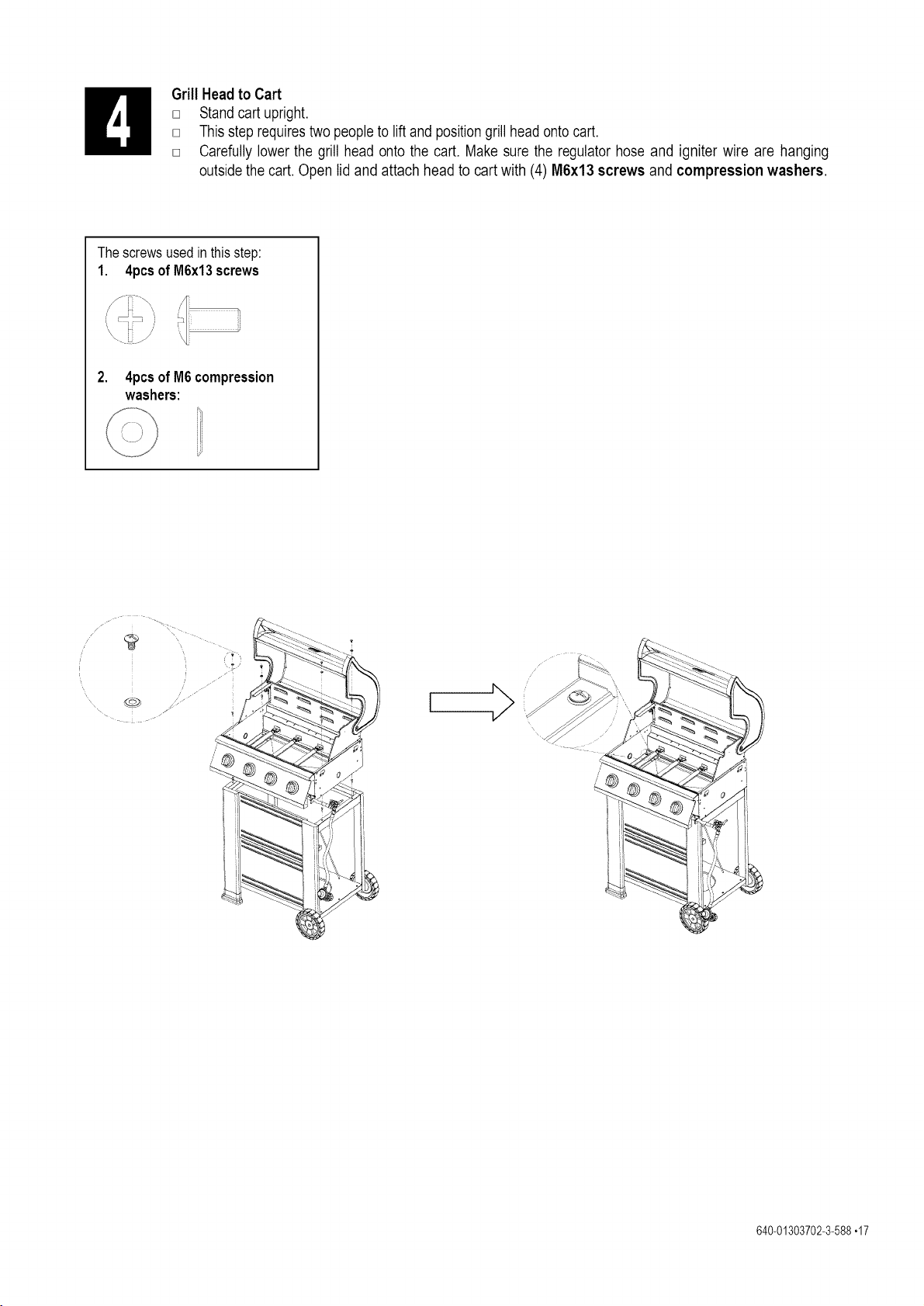
H Grill Head to Cart
[] Stand cart upright.
[] This step requirestwo people to lift and positiongrill head onto cart.
[] Carefully lower the grill head onto the cart, Make sure the regulator hose and igniter wire are hanging
outsidethe cart. Open lid and attach head to cart with (4) MGx13screws and compression washers.
The screwsusedinthis step:
1. 4pcsofM6x13screws
2. 4pcsofM6compression
washers:
640-01303702-3-588,17
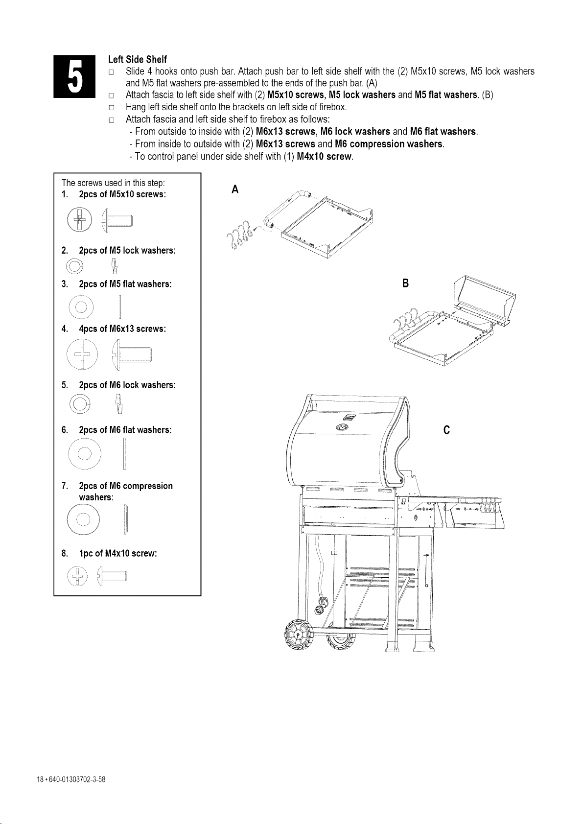
Left Side Shelf
[] Slide 4 hooks onto push bar. Attach push bar to left side shelf with the (2) M5xl0 screws, M5 lock washers
and M5 flat washers pre-assembledto the ends of the push bar. (A)
[] Attach fascia to leftside shelf with (2) M5xl0 screws, M5 lock washers and M5 flat washers. (B)
[] Hangleft side shelf onto the brackets on left side of firebox.
[] Attach fascia and left side shelf to firebox as follows:
- From outside to inside with (2) M6x13 screws, M6 lock washers and M6 flat washers.
- From inside to outside with (2) M6x13 screws and M6 compression washers.
- To control panel under side shelf with (1) M4xl0 screw.
The screwsusedinthis step:
1. 2pcsofM5xlOscrews:
2. 2pcsof M5 Iockwashers:
3. 2pcsof M5flat washers:
4. 4pcsofM6x13screws:
5. 2pcsof M6Iockwashers:
6. 2pcsof M6flat washers:
7. 2pcsofM6compression
washers:
8. lpcofM4xl0screw:
A
B
C
18. 640-01303702-3-58
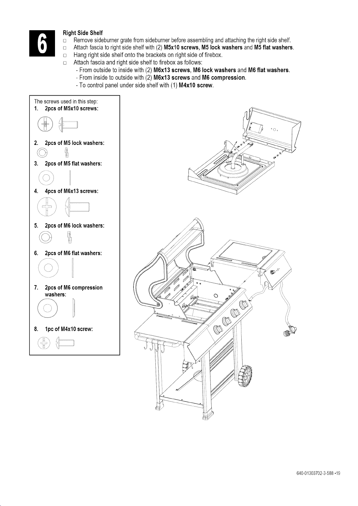
RightSide Shelf
[] Removesideburner gratefrom sideburner beforeassemblingand attachingthe rightside shelf.
[] Attach fascia to right side shelfwith (2) M5xl0 screws, M5 lock washers and M5 flat washers.
[] Hang right side shelf onto the brackets on right side of firebox.
[] Attach fascia and right side shelf to firebox as follows:
- From outside to inside with (2) M6x13 screws, M6 lock washers and M6 flat washers.
- From inside to outside with (2) M6x13 screws and M6 compression.
- To control panel under side shelf with (1) M4xlO screw.
The screwsusedinthis step:
1. 2pcsofM5xlOscrews:
2. 2pcsof M5 Iockwashers:
3. 2pcsof M5flat washers:
4. 4pcsofM6x13screws:
5. 2pcsof M6Iockwashers:
6. 2pcsof M6flat washers:
7. 2pcsofM6compression
washers:
8. lpcofM4xlOscrew:
<:_P' 'i
©
640-01303702-3-588,19
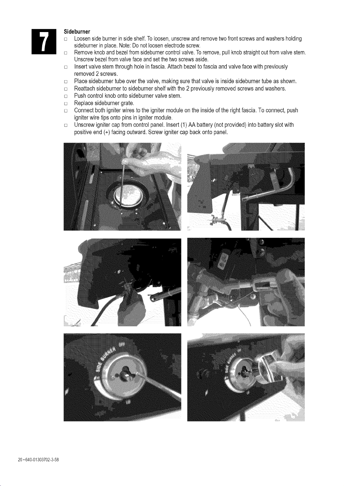
Sideburner
[] Loosenside burner in side shelf. To loosen,unscrewand removetwo front screws and washers holding
sideburnerin place. Note: Do not loosenelectrodescrew.
[] Removeknob and bezelfrom sideburnercontrol valve. To remove,pull knob straightout from valve stem.
Unscrewbezel from valve face and set the two screws aside.
[] Insert valve stem through hole in fascia. Attach bezel to fascia and valve face with previously
removed 2 screws.
[] Place sideburner tube over the valve, making sure that valve is inside sideburner tube as shown.
[] Reattach sideburner to sideburner shelf with the 2 previously removed screws and washers.
[] Push control knob onto sideburner valve stem.
[] Replace sideburnergrate.
[] Connect both igniter wires to the igniter module on the inside of the right fascia. To connect, push
igniter wire tips onto pins in igniter module.
[] Unscrew igniter cap from control panel. Insert (1) AA battery (not provided) into battery slot with
positive end (+) facing outward. Screw igniter cap back onto panel.
20,640-01303702-3-58

HeatDiffusers, Cooking Grate and Warming Rack
[] Placeheat diffusers over burners by inserting tabs into slots in front and back of firebox..
[] Placecookinggrates onto grate rests.
[] Insertwarmingrack into bracketsat top of firebox as shown.
640-01303702-3-588,21
D []
[]
[]
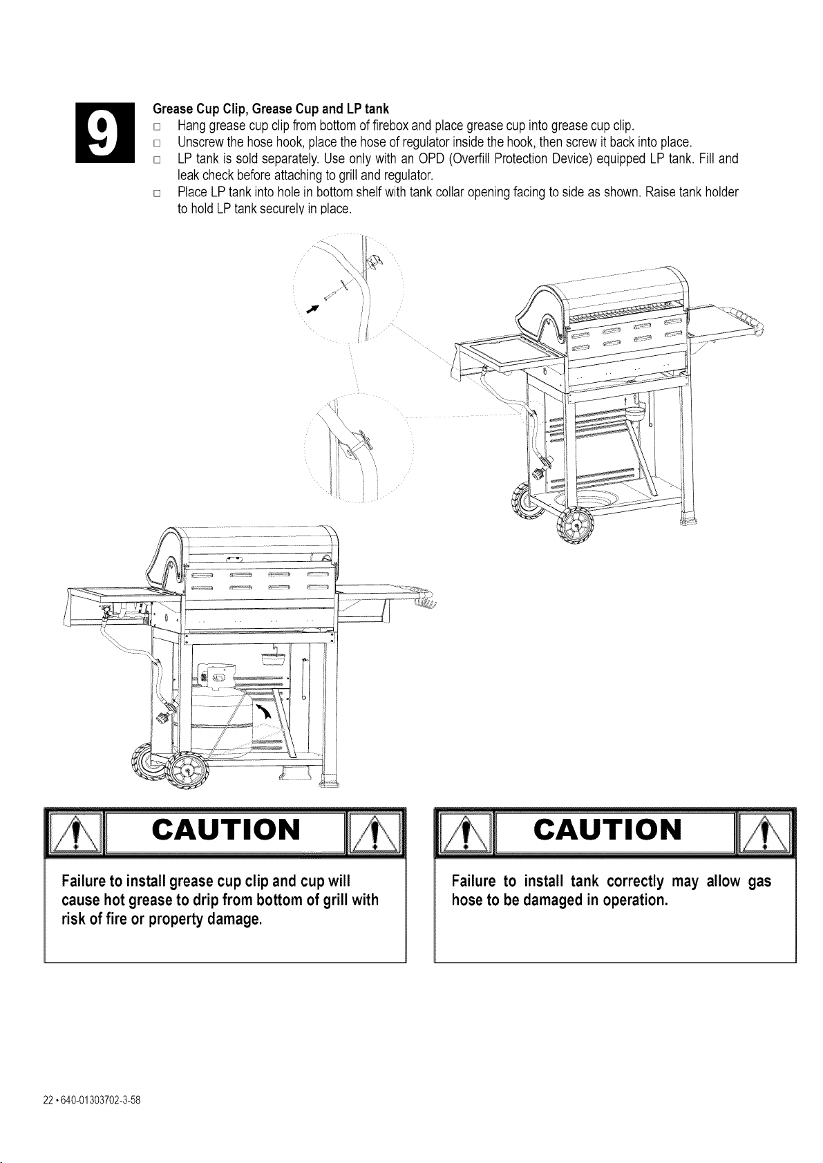
Grease Cup Clip, Grease Cup and LP tank
Hanggrease cup clip from bottom of fireboxand place grease cup into grease cup clip.
Unscrewthe hose hook, place the hose of regulatorinside the hook, then screw it back into place.
LP tank is sold separately.Use only with an OPD (Overfill ProtectionDevice) equipped LP tank. Fill and
leak check before attachingto grill and regulator.
[] PlaceLP tank into holein bottomshelf with tank collar opening facing to side as shown. Raise tank holder
to hold LPtank securelyin place.
cAuT,o.
I..........................................................................!
Failure to install grease cup clip and cup will
cause hot grease to drip from bottom of grill with
risk of fire or property damage.
Failure to install tank correctly may allow gas
hose to be damaged in operation.
22,640-01303702-3-58
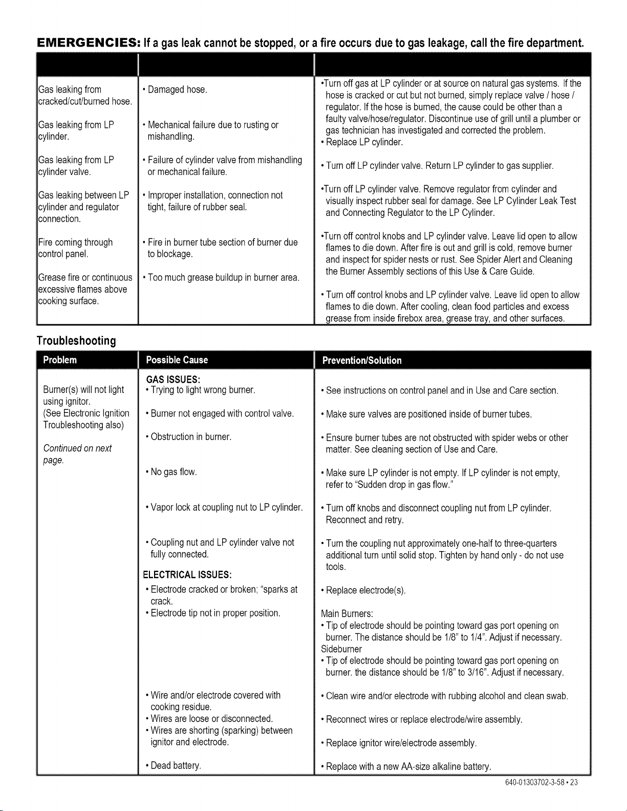
EMERGENCIES: If a gas leak cannot be stopped, or a fire occurs due to gas leakage, call the fire department.
Sasleakingfrom
._racked/cut/burnedhose.
SasleakingfromLP
._ylinder.
SasleakingfromLP
._ylindervalve.
SasleakingbetweenLP
._ylinderand regulator
._onnection.
Firecomingthrough
._ontrolpanel.
Sreasefire orcontinuous
_=xcessiveflamesabove
._ookingsurface.
Troubleshooting
• Damagedhose.
• Mechanicalfailuredue to rustingor
mishandling.
• Failureof cylindervalvefrom mishandling
or mechanicalfailure.
• Improperinstallation,connectionnot
tight,failureof rubberseal.
• Fire inburnertubesectionof burnerdue
to blockage.
• Too muchgreasebuildupin burnerarea.
GASISSUES:
•Turnoffgas at LP cylinderor at sourceon naturalgassystems. Ifthe
hoseis crackedor cut but notburned,simplyreplacevalve/ hose/
regulator.Ifthe hose is burned,the causecouldbe otherthana
faultyvalve/hose/regulator.Discontinueuse of grilluntila plumberor
gastechnicianhasinvestigatedand correctedthe problem.
• ReplaceLP cylinder.
• Turnoff LPcylindervalve.ReturnLPcylinderto gassupplier.
•Turnoff LPcylindervalve.Removeregulatorfrom cylinderand
visuallyinspectrubbersealfor damage.SeeLPCylinderLeakTest
andConnectingRegulatorto theLP Cylinder.
•Turnoffcontrolknobsand LPcylindervalve.Leavelid opento allow
flamesto diedown.Afterfire is out andgrill is cold,removeburner
andinspectfor spidernestsor rust.See SpiderAlertandCleaning
the BurnerAssemblysectionsof thisUse & CareGuide.
• Turnoffcontrol knobsand LP cylindervalve.Leavelid opento allow
flamesto diedown.Aftercooling,cleanfood particlesandexcess
greasefrom insidefireboxarea,greasetray,and othersurfaces.
Burner(s)will not light
usingignitor.
(SeeElectronicIgnition
Troubleshootingalso)
Continuedonnext
page.
• Tryingto lightwrongburner.
• Burnernotengagedwith controlvalve.
• Obstructionin burner.
• No gasflow.
• Vaporlock at couplingnut to LP cylinder.
• Couplingnutand LPcylindervalve not
fullyconnected.
ELECTRICALISSUES:
• Electrodecrackedor broken;"sparksat
crack.
• Electrodetip not in properposition.
• Wireand/orelectrodecoveredwith
cookingresidue.
• Wiresare looseor disconnected.
• Wiresare shorting(sparking)between
ignitorand electrode.
• Deadbattery.
• See instructionsoncontrolpanelandin Use andCaresection.
• Makesure valvesare positionedinsideof burnertubes.
• Ensureburnertubesare notobstructedwith spiderwebsor other
matter.Seecleaningsectionof Use andCare.
• Makesure LPcylinderis notempty. If LPcylinderis not empty,
referto "Suddendrop in gasflow."
• Turnoff knobsand disconnectcouplingnutfromLP cylinder.
Reconnectand retry.
• Turnthe couplingnutapproximatelyone-halfto three-quarters
additionalturn untilsolidstop.Tightenby handonly- do not use
tools.
• Replaceelectrode(s).
MainBurners:
• Tip of electrodeshouldbe pointingtowardgasportopeningon
burner.Thedistanceshouldbe 1/8"to 1/4".Adjustif necessary.
Sideburner
• Tip of electrodeshouldbe pointingtowardgasportopeningon
burner,the distanceshouldbe 1/8"to 3/16".Adjustif necessary.
• Cleanwireand/orelectrodewith rubbingalcoholand cleanswab.
• Reconnectwires or replaceelectrode/wireassembly.
• Replaceignitorwire/electrodeassembly.
• Replacewith a newAA-sizealkalinebattery.
640-01303702-3-58,23
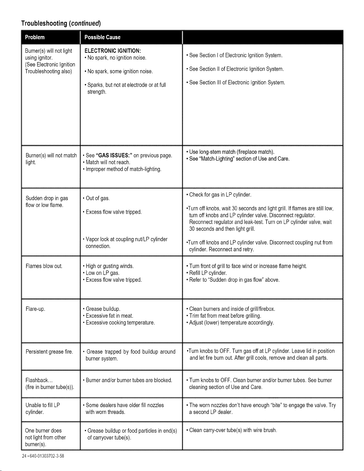
Troubleshooting (continued)
Burner(s)will not light
usingignitor.
(SeeElectronicIgnition
Troubleshootingalso)
Burner(s)will not match
light.
ELECTRONICIGNITION:
• No spark,no ignitionnoise.
• No spark,some ignitionnoise.
• Sparks,but notat electrodeor at full
strength.
• See SectionI of ElectronicIgnitionSystem.
• See SectionIIof ElectronicIgnitionSystem.
• See SectionIll of ElectronicIgnitionSystem.
• Use long-stemmatch(fireplacematch).
• See "GAS ISSUES:"on previouspage. • See "Match-Lighting"sectionof Useand Care.
• Matchwill not reach.
• Impropermethodof match-lighting.
• Checkfor gas in LPcylinder.
Suddendropin gas • Out of gas.
flowor lowflame.
•Turnoff knobs,wait 30 secondsandlightgrill. If flamesare stilllow,
• Excessflow valvetripped, turnoff knobsand LP cylindervalve.Disconnectregulator.
Reconnectregulatorand leak-test.Turn on LPcylindervalve,wait
30secondsand thenlight grill.
• Vaporlock at couplingnut/LPcylinder •Turnoff knobsand LPcylindervalve.Disconnectcouplingnutfrom
connection, cylinder.Reconnectand retry.
Flamesblowout.
Flare-up.
Persistentgreasefire.
• Highor gustingwinds.
• Lowon LPgas.
• Excessflow valvetripped.
• Greasebuildup.
• Excessivefat in meat.
• Excessivecookingtemperature.
• Grease trappedby food buildup around
burnersystem.
Flashback... • Burnerand/orburnertubesare blocked.
(fire in burnertube(s)).
• Turnfrontof grillto facewindor increaseflame height.
• Refill LPcylinder.
• Referto "Suddendropin gasflow"above.
• Cleanburnersand insideof grill/firebox.
• Trimfat from meatbeforegrilling.
• Adjust(lower)temperatureaccordingly.
•Turnknobsto OFF.Turngas offat LPcylinder.Leavelid inposition
andletfire burnout.Aftergrillcools,removeandcleanallparts.
• Turnknobsto OFF.Cleanburnerand/orburnertubes.Seeburner
cleaningsectionof UseandCare.
Unableto fill LP • Somedealershaveolderfill nozzles • Theworn nozzlesdon'thaveenough"bite"to engagethevalve.Try
cylinder, withwornthreads, a secondLPdealer.
Oneburnerdoes • Greasebuilduporfood particlesin end(s) • Cleancarry-overtube(s)with wire brush.
not lightfromother of carryovertube(s).
burner(s).
24 °640-01303702-3-58
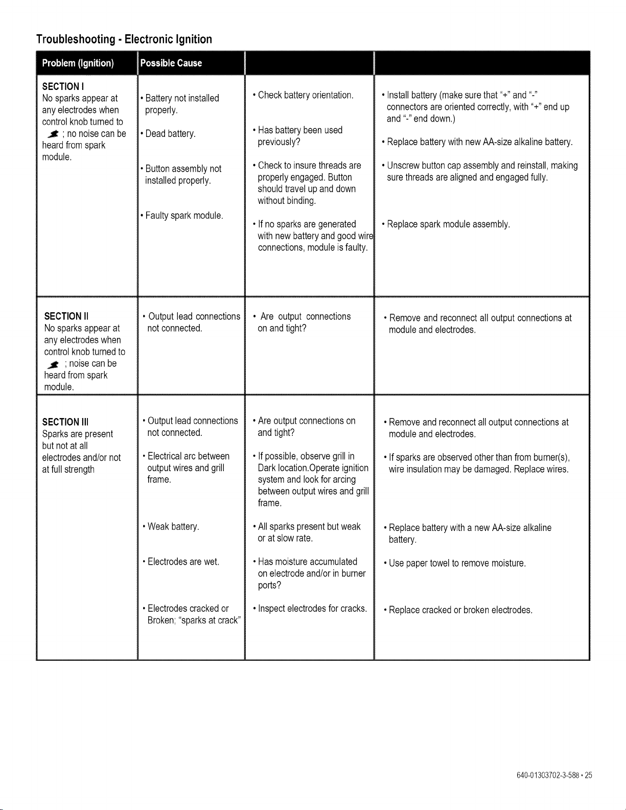
Troubleshooting- Electronic Ignition
SECTIONI
No sparksappearat
anyelectrodeswhen
controlknobturnedto
; nonoisecan be
heardfromspark
module.
Batterynot installed
properly.
Deadbattery.
Buttonassemblynot
installedproperly.
Faultysparkmodule.
• Checkbatteryorientation.
Hasbatterybeen used
previously?
Checkto insurethreadsare
properlyengaged.Button
shouldtravel up anddown
withoutbinding.
If nosparksaregenerated
withnewbatteryand good wir_
connections,moduleisfaulty.
• Installbattery(makesurethat"+" and "-"
connectorsareorientedcorrectly,with"+"end up
and"-"enddown.)
• ReplacebatterywithnewAA-sizealkalinebattery.
• Unscrewbuttoncap assemblyandreinstall,making
surethreadsare alignedand engagedfully.
• Replacespark moduleassembly.
SECTIONII • Output leadconnections • Are output connections • Removeandreconnectall outputconnectionsat
No sparksappearat notconnected, onand tight? moduleand electrodes.
anyelectrodeswhen
controlknobturnedto
' noisecan be
heardfromspark
module.
• Outputlead connections
notconnected.
• Electricalarcbetween
outputwiresandgrill
frame.
• Weak battery.
• Electrodesarewet.
• Electrodescrackedor
Broken;"sparksat crack"
SECTIONIII
Sparksarepresent
but notat all
electrodesand/ornot
at full strength
• Are outputconnectionson
andtight?
• If possible,observegrillin
Darklocation.Operateignition
systemand lookfor arcing
betweenoutputwiresandgrill
frame.
• All sparkspresentbutweak
orat slowrate.
• Has moistureaccumulated
onelectrodeand/orin burner
ports?
• Inspectelectrodesfor cracks.
• Removeandreconnectall outputconnectionsat
moduleand electrodes.
• If sparksareobservedotherthan from burner(s),
wireinsulationmay bedamaged.Replacewires.
•Replacebatterywitha newAA-sizealkaline
battery.
• Use papertowelto removemoisture.
• Replacecrackedor brokenelectrodes.
640-01303702-3-588°25

26.640-01303702-3-58

640-01303702-3-588,27
Your Home
For expert troubleshootingand home solutionsadvice:
www.managemyhome.com
For repair - in your home - of all major brand appliances,
lawn and garden equipment, or heating and cooling systems,
no matter who made it, no matter who sold it!
For the replacement parts, accessories and owner's
manuals that you need to do-it-yourself. For Sears
professional installation of home appliances and
items like garage door openers and water heaters.
1-800-4-MY-H OME_(1-800-469-4663)
Call anytime, day or night (U.S.A. and Canada)
www.sears.com www.sears.ca
Our Home
For repair of carry-in items like vacuums, lawn equipment,
And electronics, call anytime for the location of your nearest
Sears Parts & Repair Service Center
1-800-488-1222 (U.S.A) 1-800-469-4663 (Canada)
www.sears.com www.sears.ca
To purchase a protection agreement on a product serviced by Sears:
1-800-827-6655 (U.S.A.) 1-800-361-6665 (Canada)
Para pedir servicio de reparaci6n
a domicilio, y para ordenar piezas
1-888-SU-HOGAR ®
(1-888-784-6427)
Au Canada pour service en fran(_ais:
1-800-LE-FOYER Mc
(1-800-533-6937)
® Registered Trademark / T._Trademark / sMService Mark of Sears Brands, LLC
® Marca Registrada / TMMarca de F&brica / _'_Marca de Servicio de Sears Brands, LLC
MoMarque de commerce / '_° Marque depos6e de Sears Brands, LLC © Sears Brands, LLC