Loading ...
Loading ...
Loading ...
BOTH MODELS
MOUNTING THE MOTOR
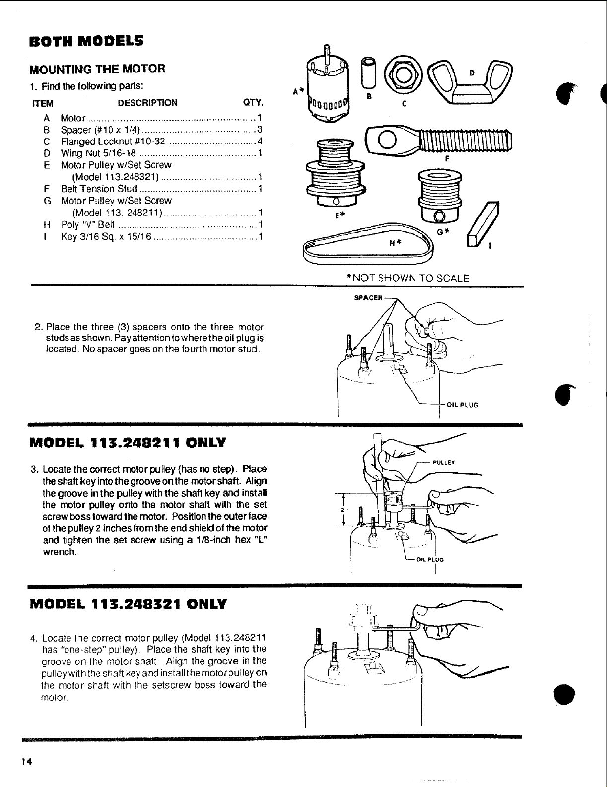
1. Findthe following parts:
ITEM DESCRIPTION QTY.
A Motor .............................................................. 1
B Spacer (#10 x 1/4) .......................................... 3
C Flanged Locknut #10-32 ................................ 4
D Wing Nut 5/16-18 ........................................... 1
E Motor Pulleyw/Set Screw
(Model 113.248321) ................................... 1
F Belt Tension Stud ........................................... 1
G Motor Pulleyw/Set Screw
(Model 113. 248211) .................................. 1
H Poly "V" Belt ................................................... 1
I Key 3/16 Sq x 15/16 ...................................... 1
*NOT SHOWN TO SCALE
2. Place the three (3) spacers onto the three motor
studs asshown. Pay attention towhere the oil plug is
located, No spacer goes on the fourth motor stud.
MODEL 113.248211 ONLY
3. Locate the correct motor pulley (has no step). Place
theshaft key intothe groove onthe motorshaft. Align
the groove inthe pulley with the shaft key and install
the motor pulley onto the motor shaft with the set
screw boss towardthe motor. Positionthe outerlace
ofthe pulley 2 inches fromthe end shieldofthe motor
and tighten the set screw using a 1/8-inch hex "L"
wrench.
PULLEY
OIL PLUG
MODEL 113.248321 ONLY
4. Locate the correct motor pulley (Model 113.248211
has "one-step" pulley). Place the shaft key into the
groove on the motor shaft. Align the groove in the
pulley wit h the shaft key and install the motor pulley on
the motor shaft with the setscrew boss toward the
motor,
e
14
Loading ...
Loading ...
Loading ...