Loading ...
Loading ...
Loading ...
ASSEMBLY
INSTALLING THE GUIDE BAR AND
SAW CHAIN
CAUTION: Sharpchain. Always
wear protective gloves when handling
the chain. The chain is sharp and can cut
you when it is not running.
2_WARNING: Sharp moving chain.
To prevent accidental operation, ensure
that battery is removed from the tool
before performing the fotlowing
operations. Failure to do this could result in
serious personal injury.
The saw chain (5) and guide bar (4) are
packed separately in the carton. The chain
has to be attached to the bar, and both must
be attached to the body of the tool.
• Place the saw on a firm surface.
• Rotate the bar adjust locking knob (7)
counterclockwise as shown m Figure B
to remove sprocket cover (6).
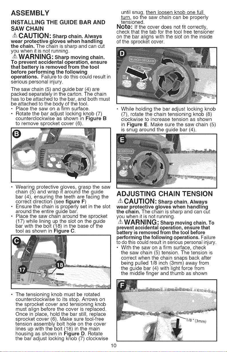
until snug, then loosen knob one full
turn, so the saw chain can be properly
tensioned.
Note: If the cover does not fit correctly,
check that the tab for the tool free tensioner
on the bar aligns with the slot on the inside
of the sprocket cover.
While holding the bar adjust locking knob
(7), rotate the chain tensioning knob (8)
clockwise to increase tension as shown
in Figure E. Make sure the saw chain (5)
is snug around the guide bar (4).
• Wearing protective gloves, grasp the saw
chain (5) and wrap it around the guide
bar (4), ensuring the teeth are facing the
correct direction (see figure F)
• Ensure the chain is properly set in the slot
around the entire guide bar.
Place the saw chain around the sprocket
(17) while lining up the slot on the guide
bar with the bolt (18) in the base of the
tool as shown in Figure C.
ADJUSTING CHAIN TENSION
zLCAUTION: Sharp chain. Always
wear protective gloves when handling
the chain. The chain is sharp and can cut
you when it is not running.
zLWARNING: Sharp moving chain. To
prevent accidental operation, ensure that
battery is removed from the tool before
performing the following operations. Failure
to do this could result in serious personal injury.
• With the saw on a firm surface, check
the saw chain (5) tension. The tension is
correct when the chain snaps back after
being pulled 1/8 inch (3mm) away from
the guide bar (4) with light force from
the middle finger and thumb as shown
• The tensioning knob must be rotated
counterclockwise to its stop. Arrows on
the sprocket cover and tensioning knob
must align before the cover is replaced.
Once in place, hold the bar still, replace
sprocket cover (6). Make sure tool-free
tension assembly bolt hole on the cover
lines up with the bott (18) in the main
housing as shown in Figure D. Rotate
the bar adjust locking knob (7) clockwise
10
Loading ...
Loading ...
Loading ...