Loading ...
Loading ...
Loading ...
INSTALL MITER GAUGE
Refer to Figure 7.
• The miter gauge comes preassembled. Unpack the miter
gauge and clean thoroughly. Be certain miter gauge
T-slots in table are also thoroughly cleaned.
• The miter gauge is guided through the T-slot with a roller
guide at the front of guide bar. To insert miter gauge, first
insert roller guide into T-slot at front of table (Key No. 12).
OUTFEED TABLE ASSEMBLY
Refer to Figure 7.
• Attach support retainer (Key No. 46) to the lower rear of
the cabinet with two M6 x 25mm hex head screws, M6
lock washers and M6 flat washers (Key Nos. 22, 23 and
47). Do not completely tighten hardware.
• Assemble the lower support (Key No. 45) to the support
retainer with one M6 x 35mm hex head screw and M6
Nylok hex nut (Key Nos. 48 and 49). Be sure that the
notch in the lower support is facing up. Do not completely
tighten hex nut. Allow lower support to move freely.
• Place clamp knob (Key No. 44) through slot of upper sup-
port (Key No. 43), making sure that the rounded corner of
the upper support is facing towards notch in lower sup-
port. Thread clamp knob into threaded hole of lower sup-
port.
• Fold out lower and upper support arm bars, so that the pin
in the upper support goes into notch of lower support and
securely tighten clamp knob.
• Assemble both hinge assemblies (Key No. 42) to the out-
feed table assembly (Key No. 41) with four M5 x 16mm
hex head screws, M5 lock washers and M5 flat washers.
Make sure washers and hex nuts are placed under the
outfeed table. Do not completely tighten hardware.
• Assemble the hinges on the outfeed table to the top of the
rear rail through existing holes with four M5 x 16mm hex
head screws, M5 lock washers and M5 flat washers.
Secure the hex head screws with four M5 flat washers and
M5 hex nuts placed under the rear rail. Do not completely
tighten hardware.
• Attach upper support bar to tab underneath outfeed table
using one M6 x 35 hex head screw and one M6 Nylok hex
nut. Do not completely tighten hex nut. Allow upper sup-
port to move freely.
• Tighten hardware attaching the hinges to both rear rail and
outfeed table.
• Make sure the clearance miter gauge grooves in the out-
feed table align with the table saw's miter gauge grooves.
Place a straight edge on the saw table overhanging the
outfeed table. Make sure the outfeed table is level or
slightly below the saw table and securely tighten hardware
attaching support retainer to cabinet.
ELECTRICAL CONNECTIONS
GROUNDING INSTRUCTIONS
WARNING: Improper connection of equipment grounding con-
ductor can result inthe risk of electrical shock. Equipment should
be grounded while in use to protect operator from electrical shock.
• Check with a qualified electrician if grounding instructions
are not understood or if in doubt as to whether the tool is
properly grounded.
• This tool is equipped with an approved 3-conductor cord
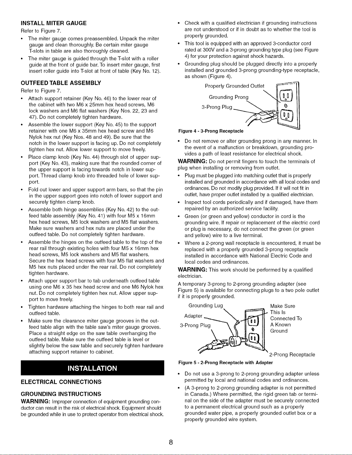
rated at 300V and a 3-prong grounding type plug (see Figure
4) for your protection against shock hazards.
• Grounding plug should be plugged directly into a properly
installed and grounded 3-prong grounding-type receptacle,
as shown (Figure 4).
Properly Grounded Outlet _"_"'_
Grounding Prong
3-Prong Plug
Figure 4 - 3-Prong Receptacle
• Do not remove or alter grounding prong in any manner. In
the event of a malfunction or breakdown, grounding pro-
vides a path of least resistance for electrical shock.
WARNING: Do not permit fingers to touch the terminals of
plug when installing or removing from outlet.
• Plug must be plugged into matching outlet that is properly
installed and grounded in accordance with all local codes and
ordinances. Do not modify plug provided. If it will not fit in
outlet, have proper outlet installed by a qualified electrician.
• Inspect tool cords periodically and if damaged, have them
repaired by an authorized service facility.
• Green (or green and yellow) conductor in cord is the
grounding wire. If repair or replacement of the electric cord
or plug is necessary, do not connect the green (or green
and yellow) wire to a live terminal.
• Where a 2-prong wall receptacle is encountered, it must be
replaced with a properly grounded 3-prong receptacle
installed in accordance with National Electric Code and
local codes and ordinances.
WARNING: This work should be performed by a qualified
electrician.
A temporary 3-prong to 2-prong grounding adapter (see
Figure 5) is available for connecting plugs to a two pole outlet
if it is properly grounded.
Grounding Lug Make Sure
This Is
Ada Connected To
3-Prong Plug A Known
Ground
2-Prong Receptacle
Figure 5 - 2-Prong Receptacle with Adapter
Do not use a 3-prong to 2-prong grounding adapter unless
permitted by local and national codes and ordinances.
(A 3-prong to 2-prong grounding adapter is not permitted
in Canada.) Where permitted, the rigid green tab or termi-
nal on the side of the adapter must be securely connected
to a permanent electrical ground such as a properly
grounded water pipe, a properly grounded outlet box or a
properly grounded wire system.
8
Loading ...
Loading ...
Loading ...