
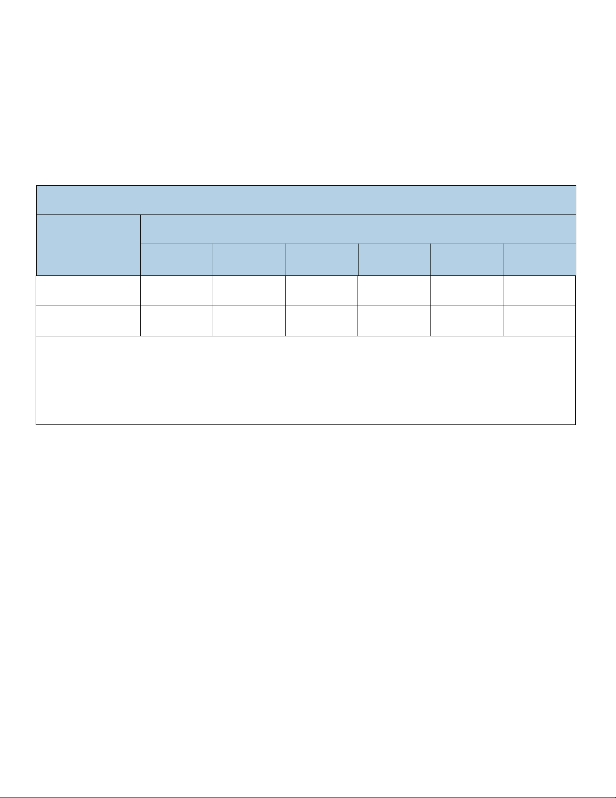
Standard models
ST3000DM008
ST2000DM006
ST1000DM010
ST500DM009
Self-Encryption models
ST3000DM009
ST2000DM007
100804187, Rev. F
November 2017
Product Manual
© 2017 Seagate Technology LLC. All rights reserved.
Publication number: 100804187, Rev. F November 2017
Seagate, Seagate Technology, BarraCuda and the Spiral logo are registered trademarks of Seagate Technology LLC in the United States and/or other countries. AcuTrac, OptiCache, Smar-
tAlign and SeaTools are either trademarks or registered trademarks of Seagate Technology LLC or one of its affiliated companies in the United States and/or other countries. All other
trademarks or registered trademarks are the property of their respective owners.
No part of this publication may be reproduced in any form without written permission of Seagate Technology LLC.
Call 877-PUB-TEK1(877-782-8351) to request permission.
When referring to drive capacity, one gigabyte, or GB, equals one billion bytes and one terabyte, or TB, equals one trillion bytes. Your computer’s operating system may use a different
standard of measurement and report a lower capacity. In addition, some of the listed capacity is used for formatting and other functions, and thus will not be available for data storage.
Actual quantities will vary based on various factors, including file size, file format, features and application software. Actual data rates may vary depending on operating environment and
other factors. The export or re-export of hardware or software containing encryption may be regulated by the U.S. Department of Commerce, Bureau of Industry and Security (for more
information, visit www.bis.doc.gov), and controlled for import and use outside of the U.S. Seagate reserves the right to change, without notice, product offerings or specifications.
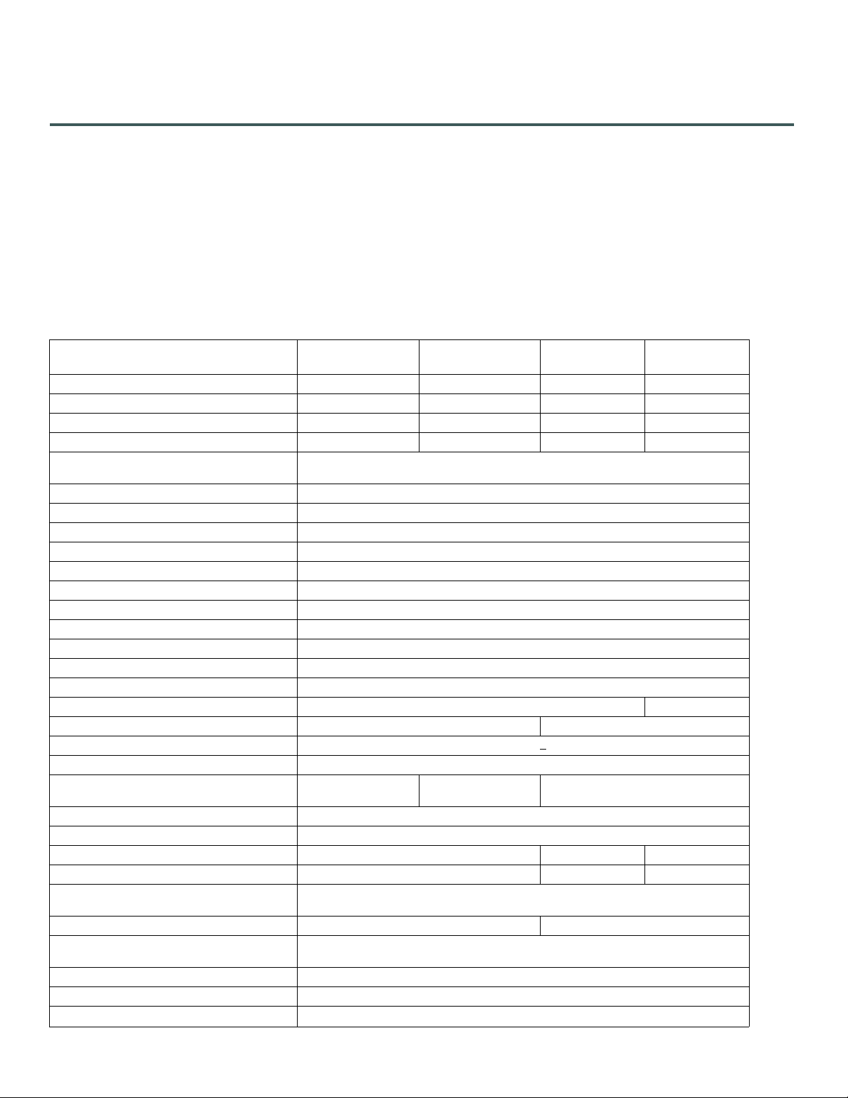
Document Revision History
Revision Date Description of Change
Rev. A 07/08/2016 Initial release.
Rev. B 11/29/2016
fc: Placed new BarraCuda logo
19: Added MSIP Korean text for Class B device warning
Rev. C 02/22/2017
23: Revised base deck option statement
25: Add Figure 5 mechanical drawing & note
Rev. D 06/21/2017
8 & 11: Revised Max height to 20.20 mm
23-25: Revised Mechanical Drawings (Figs 3-5) Z-heights to 20.20 mm
Rev. E 09/28/2017 18-21: Updated Safety, EMC, FCC & RoHS Sections 2.13 through 2.14.3, per Compliance Council
Rev. F 11/03/2017
15: Added Figure 1: Location of the HDA temperature check point
22: Updated Table 7: Taiwan - Restricted Substances - Unit row headers = HDD & PCBA
24-27: Updated fastener penetration depth in Section 3.4 & Fig. 3-6 = 0.140 in.

Seagate BarraCuda Product Manual, Rev. F 2
Contents
Seagate® Technology Support Services . . . . . . . . . . . . . . . . . . . . . . . . . . . . . . . . . . . . . . . . . . . . . . . . . . . . . . . . . . . . . . . 5
1.0 Introduction . . . . . . . . . . . . . . . . . . . . . . . . . . . . . . . . . . . . . . . . . . . . . . . . . . . . . . . . . . . . . . . . . . . . . . . . . . . . . . . . . 6
1.1 About the SATA interface . . . . . . . . . . . . . . . . . . . . . . . . . . . . . . . . . . . . . . . . . . . . . . . . . . . . . . . . . . . . . . . . . . . . . 7
2.0 Drive Specifications . . . . . . . . . . . . . . . . . . . . . . . . . . . . . . . . . . . . . . . . . . . . . . . . . . . . . . . . . . . . . . . . . . . . . . . . . . 8
2.1 Specification summary tables . . . . . . . . . . . . . . . . . . . . . . . . . . . . . . . . . . . . . . . . . . . . . . . . . . . . . . . . . . . . . . . . . 8
2.2 Formatted capacity . . . . . . . . . . . . . . . . . . . . . . . . . . . . . . . . . . . . . . . . . . . . . . . . . . . . . . . . . . . . . . . . . . . . . . . . . . 10
2.2.1 LBA mode. . . . . . . . . . . . . . . . . . . . . . . . . . . . . . . . . . . . . . . . . . . . . . . . . . . . . . . . . . . . . . . . . . . . . . . . . 10
2.3 Default logical geometry. . . . . . . . . . . . . . . . . . . . . . . . . . . . . . . . . . . . . . . . . . . . . . . . . . . . . . . . . . . . . . . . . . . . . 10
2.4 Recording and interface technology. . . . . . . . . . . . . . . . . . . . . . . . . . . . . . . . . . . . . . . . . . . . . . . . . . . . . . . . . . 10
2.5 Physical characteristics . . . . . . . . . . . . . . . . . . . . . . . . . . . . . . . . . . . . . . . . . . . . . . . . . . . . . . . . . . . . . . . . . . . . . . 11
2.6 Seek time . . . . . . . . . . . . . . . . . . . . . . . . . . . . . . . . . . . . . . . . . . . . . . . . . . . . . . . . . . . . . . . . . . . . . . . . . . . . . . . . . . . 11
2.7 Start/stop times . . . . . . . . . . . . . . . . . . . . . . . . . . . . . . . . . . . . . . . . . . . . . . . . . . . . . . . . . . . . . . . . . . . . . . . . . . . . . 12
2.8 Power specifications . . . . . . . . . . . . . . . . . . . . . . . . . . . . . . . . . . . . . . . . . . . . . . . . . . . . . . . . . . . . . . . . . . . . . . . . . 12
2.8.1 Power consumption . . . . . . . . . . . . . . . . . . . . . . . . . . . . . . . . . . . . . . . . . . . . . . . . . . . . . . . . . . . . . . . 12
2.8.2 Conducted noise . . . . . . . . . . . . . . . . . . . . . . . . . . . . . . . . . . . . . . . . . . . . . . . . . . . . . . . . . . . . . . . . . . 13
2.8.3 Voltage tolerance . . . . . . . . . . . . . . . . . . . . . . . . . . . . . . . . . . . . . . . . . . . . . . . . . . . . . . . . . . . . . . . . . 13
2.8.4 Power-management modes . . . . . . . . . . . . . . . . . . . . . . . . . . . . . . . . . . . . . . . . . . . . . . . . . . . . . . . 14
2.9 Environmental specifications. . . . . . . . . . . . . . . . . . . . . . . . . . . . . . . . . . . . . . . . . . . . . . . . . . . . . . . . . . . . . . . . . 15
2.9.1 Ambient temperature . . . . . . . . . . . . . . . . . . . . . . . . . . . . . . . . . . . . . . . . . . . . . . . . . . . . . . . . . . . . . 15
2.9.2 Temperature gradient . . . . . . . . . . . . . . . . . . . . . . . . . . . . . . . . . . . . . . . . . . . . . . . . . . . . . . . . . . . . . 15
2.9.3 Humidity. . . . . . . . . . . . . . . . . . . . . . . . . . . . . . . . . . . . . . . . . . . . . . . . . . . . . . . . . . . . . . . . . . . . . . . . . . 15
2.9.4 Altitude . . . . . . . . . . . . . . . . . . . . . . . . . . . . . . . . . . . . . . . . . . . . . . . . . . . . . . . . . . . . . . . . . . . . . . . . . . . 16
2.9.5 Shock and Vibration . . . . . . . . . . . . . . . . . . . . . . . . . . . . . . . . . . . . . . . . . . . . . . . . . . . . . . . . . . . . . . . 16
2.9.6 Non-operating vibration. . . . . . . . . . . . . . . . . . . . . . . . . . . . . . . . . . . . . . . . . . . . . . . . . . . . . . . . . . . 16
2.10 Acoustics. . . . . . . . . . . . . . . . . . . . . . . . . . . . . . . . . . . . . . . . . . . . . . . . . . . . . . . . . . . . . . . . . . . . . . . . . . . . . . . . . . . . 17
2.10.1 Test for Prominent Discrete Tones (PDTs) . . . . . . . . . . . . . . . . . . . . . . . . . . . . . . . . . . . . . . . . . . 17
2.11 Electromagnetic immunity. . . . . . . . . . . . . . . . . . . . . . . . . . . . . . . . . . . . . . . . . . . . . . . . . . . . . . . . . . . . . . . . . . . 17
2.12 Reliability . . . . . . . . . . . . . . . . . . . . . . . . . . . . . . . . . . . . . . . . . . . . . . . . . . . . . . . . . . . . . . . . . . . . . . . . . . . . . . . . . . . 18
2.12.1 Annualized Failure Rate (AFR). . . . . . . . . . . . . . . . . . . . . . . . . . . . . . . . . . . . . . . . . . . . . . . . . . . . . . 18
2.12.2 Storage . . . . . . . . . . . . . . . . . . . . . . . . . . . . . . . . . . . . . . . . . . . . . . . . . . . . . . . . . . . . . . . . . . . . . . . . . . . 18
2.13 Agency and Safety Certifications . . . . . . . . . . . . . . . . . . . . . . . . . . . . . . . . . . . . . . . . . . . . . . . . . . . . . . . . . . . . . 18
2.13.1 Safety certification . . . . . . . . . . . . . . . . . . . . . . . . . . . . . . . . . . . . . . . . . . . . . . . . . . . . . . . . . . . . . . . . 18
2.13.2 European Union (EU) CE Marking Requirements . . . . . . . . . . . . . . . . . . . . . . . . . . . . . . . . . . . . 18
2.13.3 Australian RCM Compliance Mark . . . . . . . . . . . . . . . . . . . . . . . . . . . . . . . . . . . . . . . . . . . . . . . . . . 19
2.13.4 Canada ICES-003 . . . . . . . . . . . . . . . . . . . . . . . . . . . . . . . . . . . . . . . . . . . . . . . . . . . . . . . . . . . . . . . . . . 19
2.13.5 South Korean KC Certification Mark . . . . . . . . . . . . . . . . . . . . . . . . . . . . . . . . . . . . . . . . . . . . . . . . 19
2.13.6 Morocco Commodity Mark . . . . . . . . . . . . . . . . . . . . . . . . . . . . . . . . . . . . . . . . . . . . . . . . . . . . . . . . 19
2.13.7 Taiwanese BSMI . . . . . . . . . . . . . . . . . . . . . . . . . . . . . . . . . . . . . . . . . . . . . . . . . . . . . . . . . . . . . . . . . . . 19
2.13.8 FCC verification . . . . . . . . . . . . . . . . . . . . . . . . . . . . . . . . . . . . . . . . . . . . . . . . . . . . . . . . . . . . . . . . . . . 20
2.14 Environmental protection. . . . . . . . . . . . . . . . . . . . . . . . . . . . . . . . . . . . . . . . . . . . . . . . . . . . . . . . . . . . . . . . . . . . 20
2.14.1 European Union Restriction of Hazardous Substance Law. . . . . . . . . . . . . . . . . . . . . . . . . . . 20
2.14.2 China Requirements —China RoHS 2 . . . . . . . . . . . . . . . . . . . . . . . . . . . . . . . . . . . . . . . . . . . . . . 21
2.14.3 Taiwan Requirements — Taiwan RoHS . . . . . . . . . . . . . . . . . . . . . . . . . . . . . . . . . . . . . . . . . . . . . 22
2.15 Corrosive environment . . . . . . . . . . . . . . . . . . . . . . . . . . . . . . . . . . . . . . . . . . . . . . . . . . . . . . . . . . . . . . . . . . . . . . 22

Seagate BarraCuda Product Manual, Rev. F 3
Contents
3.0 Configuring and Mounting the Drive . . . . . . . . . . . . . . . . . . . . . . . . . . . . . . . . . . . . . . . . . . . . . . . . . . . . . . . . . 23
3.1 Handling and static-discharge precautions . . . . . . . . . . . . . . . . . . . . . . . . . . . . . . . . . . . . . . . . . . . . . . . . . . . 23
3.2 Configuring the drive . . . . . . . . . . . . . . . . . . . . . . . . . . . . . . . . . . . . . . . . . . . . . . . . . . . . . . . . . . . . . . . . . . . . . . . . 23
3.3 SATA cables and connectors . . . . . . . . . . . . . . . . . . . . . . . . . . . . . . . . . . . . . . . . . . . . . . . . . . . . . . . . . . . . . . . . . 23
3.4 Drive mounting . . . . . . . . . . . . . . . . . . . . . . . . . . . . . . . . . . . . . . . . . . . . . . . . . . . . . . . . . . . . . . . . . . . . . . . . . . . . . 24
4.0 About (SED) Self-Encrypting Drives. . . . . . . . . . . . . . . . . . . . . . . . . . . . . . . . . . . . . . . . . . . . . . . . . . . . . . . . . . . 28
4.1 Data Encryption . . . . . . . . . . . . . . . . . . . . . . . . . . . . . . . . . . . . . . . . . . . . . . . . . . . . . . . . . . . . . . . . . . . . . . . . . . . . . 28
4.2 Controlled Access . . . . . . . . . . . . . . . . . . . . . . . . . . . . . . . . . . . . . . . . . . . . . . . . . . . . . . . . . . . . . . . . . . . . . . . . . . . 28
4.2.1 Admin SP . . . . . . . . . . . . . . . . . . . . . . . . . . . . . . . . . . . . . . . . . . . . . . . . . . . . . . . . . . . . . . . . . . . . . . . . . 28
4.2.2 Locking SP . . . . . . . . . . . . . . . . . . . . . . . . . . . . . . . . . . . . . . . . . . . . . . . . . . . . . . . . . . . . . . . . . . . . . . . . 28
4.2.3 Default password . . . . . . . . . . . . . . . . . . . . . . . . . . . . . . . . . . . . . . . . . . . . . . . . . . . . . . . . . . . . . . . . . 28
4.2.4 ATA Enhanced Security . . . . . . . . . . . . . . . . . . . . . . . . . . . . . . . . . . . . . . . . . . . . . . . . . . . . . . . . . . . . 28
4.3 Random Number Generator (RNG) . . . . . . . . . . . . . . . . . . . . . . . . . . . . . . . . . . . . . . . . . . . . . . . . . . . . . . . . . . . 29
4.4 Drive Locking. . . . . . . . . . . . . . . . . . . . . . . . . . . . . . . . . . . . . . . . . . . . . . . . . . . . . . . . . . . . . . . . . . . . . . . . . . . . . . . . 29
4.5 Data Bands (TBD) . . . . . . . . . . . . . . . . . . . . . . . . . . . . . . . . . . . . . . . . . . . . . . . . . . . . . . . . . . . . . . . . . . . . . . . . . . . . 29
4.6 Cryptographic Erase . . . . . . . . . . . . . . . . . . . . . . . . . . . . . . . . . . . . . . . . . . . . . . . . . . . . . . . . . . . . . . . . . . . . . . . . . 29
4.7 Authenticated Firmware Download . . . . . . . . . . . . . . . . . . . . . . . . . . . . . . . . . . . . . . . . . . . . . . . . . . . . . . . . . . 29
4.8 Power Requirements . . . . . . . . . . . . . . . . . . . . . . . . . . . . . . . . . . . . . . . . . . . . . . . . . . . . . . . . . . . . . . . . . . . . . . . . 29
4.9 Supported Commands. . . . . . . . . . . . . . . . . . . . . . . . . . . . . . . . . . . . . . . . . . . . . . . . . . . . . . . . . . . . . . . . . . . . . . . 29
4.10 RevertSP . . . . . . . . . . . . . . . . . . . . . . . . . . . . . . . . . . . . . . . . . . . . . . . . . . . . . . . . . . . . . . . . . . . . . . . . . . . . . . . . . . . . 29
5.0 SATA Interface . . . . . . . . . . . . . . . . . . . . . . . . . . . . . . . . . . . . . . . . . . . . . . . . . . . . . . . . . . . . . . . . . . . . . . . . . . . . . . 30
5.1 Hot-Plug compatibility. . . . . . . . . . . . . . . . . . . . . . . . . . . . . . . . . . . . . . . . . . . . . . . . . . . . . . . . . . . . . . . . . . . . . . . 30
5.2 SATA device plug connector pin definitions . . . . . . . . . . . . . . . . . . . . . . . . . . . . . . . . . . . . . . . . . . . . . . . . . . 30
5.3 Supported ATA commands . . . . . . . . . . . . . . . . . . . . . . . . . . . . . . . . . . . . . . . . . . . . . . . . . . . . . . . . . . . . . . . . . . 31
5.3.1 Identify Device command . . . . . . . . . . . . . . . . . . . . . . . . . . . . . . . . . . . . . . . . . . . . . . . . . . . . . . . . . 33
5.3.2 Set Features command . . . . . . . . . . . . . . . . . . . . . . . . . . . . . . . . . . . . . . . . . . . . . . . . . . . . . . . . . . . . 37
5.3.3 S.M.A.R.T. commands. . . . . . . . . . . . . . . . . . . . . . . . . . . . . . . . . . . . . . . . . . . . . . . . . . . . . . . . . . . . . . 37

Seagate BarraCuda Product Manual, Rev. F 4
Figures
Figure 1 Location of the HDA temperature check point . . . . . . . . . . . . . . . . . . . . . . . . . . . . . . . . . . . . . . . . . . . . . . . . . . 15
Figure 2 Attaching SATA cabling. . . . . . . . . . . . . . . . . . . . . . . . . . . . . . . . . . . . . . . . . . . . . . . . . . . . . . . . . . . . . . . . . . . . . . . . 23
Figure 3 Mounting dimensions (2/3-disk: 2TB to 3TB models) . . . . . . . . . . . . . . . . . . . . . . . . . . . . . . . . . . . . . . . . . . . . 24
Figure 4 Mounting dimensions (configuration 1) . . . . . . . . . . . . . . . . . . . . . . . . . . . . . . . . . . . . . . . . . . . . . . . . . . . . . . . . 25
Figure 5 Mounting dimensions (configuration 2) . . . . . . . . . . . . . . . . . . . . . . . . . . . . . . . . . . . . . . . . . . . . . . . . . . . . . . . . 26
Figure 6 Mounting dimensions (configuration 3) . . . . . . . . . . . . . . . . . . . . . . . . . . . . . . . . . . . . . . . . . . . . . . . . . . . . . . . . 27

Seagate BarraCuda Product Manual, Rev. F 5
For information regarding online support and services, visit: http://www.seagate.com/contacts/
For information regarding Warranty Support, visit: http://www.seagate.com/support/warranty-and-replacements/
For information regarding data recovery services, visit: http://www.seagate.com/services-software/recover/
For Seagate OEM, Distribution partner and reseller portals, visit: http://www.seagate.com/partners/
Seagate® Technology Support Services
Seagate BarraCuda Product Manual, Rev. F 6
www.seagate.com Introduction
1.0 Introduction
This manual describes the functional, mechanical and interface specifications for the following:
Seagate® BarraCuda® model drives:
These drives provide the following key features:
• 7200 RPM spindle speed.
• Compliant with RoHS requirements in China and Europe.
• Full-track multiple-sector transfer capability without local processor intervention.
• High instantaneous (burst) data-transfer rates (up to 600MB per second).
• Native Command Queuing with command ordering to increase performance in demanding applications.
•Quiet operation.
• Seagate AcuTrac™ servo technology delivers dependable performance, even with hard drive track widths of only 75
nanometers.
• Seagate OptiCache™ technology boosts overall performance by as much as 45% over the previous generation.
• Seagate SmartAlign™ technology provides a simple, transparent migration to Advanced Format 4K sectors
• SeaTools diagnostic software performs a drive self-test that eliminates unnecessary drive returns.
• State-of-the-art cache and on-the-fly error-correction algorithms.
• Support for S.M.A.R.T. drive monitoring and reporting.
• Supports latching SATA cables and connectors.
• TGMR recording technology provides the drives with increased areal density.
• Worldwide Name (WWN) capability uniquely identifies the drive.
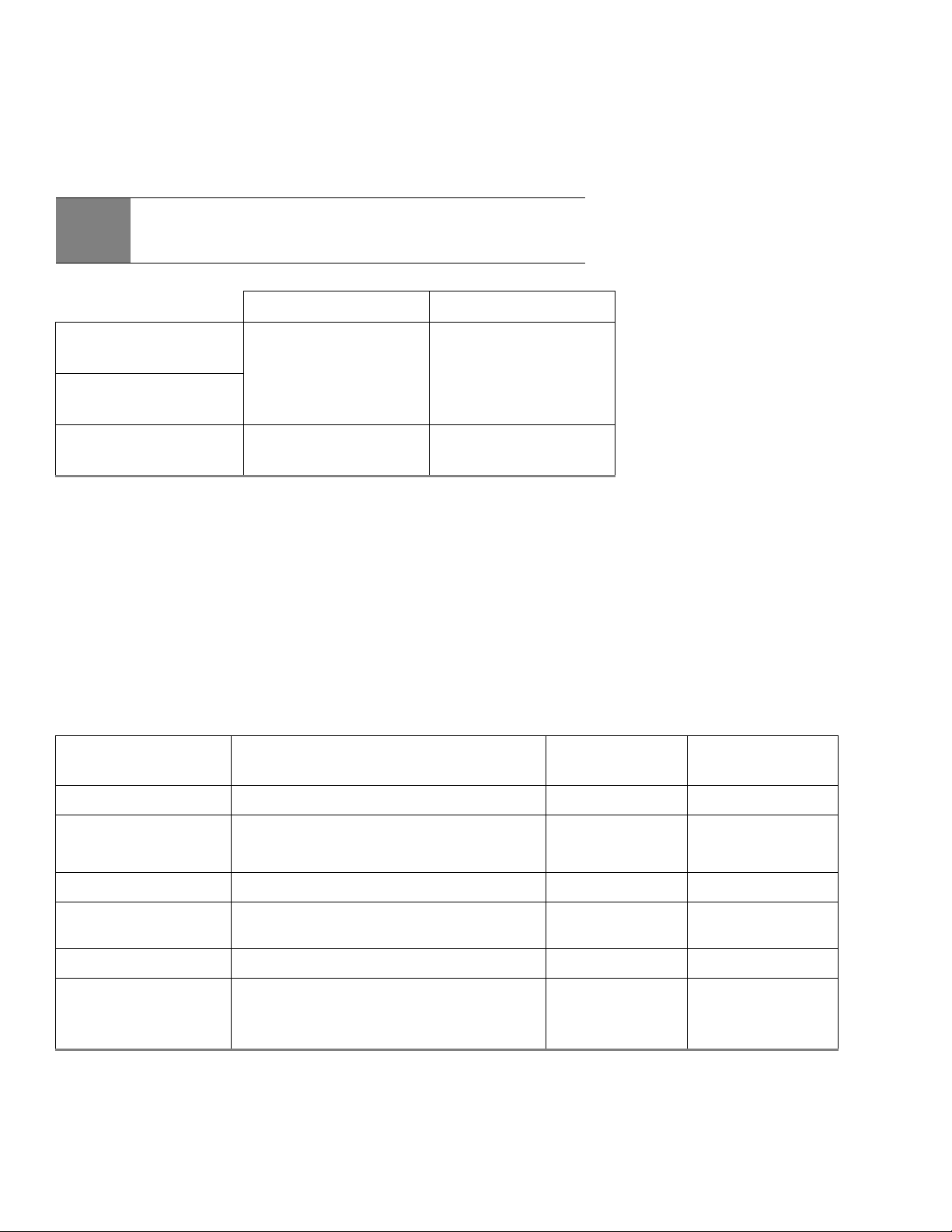
Standard models Self-Encryption models
ST3000DM008 ST1000DM010 ST3000DM009
ST2000DM006 ST500DM009 ST2000DM007
Note
Previous generations of Seagate Self-Encrypting Drive models were called Full Disk Encryption (FDE) models
before a differentiation between drive-based encryption and other forms of encryption was necessary.

Seagate BarraCuda Product Manual, Rev. F 7
www.seagate.com Introduction
1.1 About the SATA interface
The Serial ATA (SATA) interface provides several advantages over the traditional (parallel) ATA interface. The primary advantages
include:
• Easy installation and configuration with true plug-and-play connectivity. It is not necessary to set any jumpers or other
configuration options.
• Thinner and more flexible cabling for improved enclosure airflow and ease of installation.
• Scalability to higher performance levels.
In addition, SATA makes the transition from parallel ATA easy by providing legacy software support. SATA was designed to allow
users to install a SATA host adapter and SATA disk drive in the current system and expect all of the existing applications to work as
normal.
The SATA interface connects each disk drive in a point-to-point configuration with the SATA host adapter. There is no master/slave
relationship with SATA devices like there is with parallel ATA. If two drives are attached on one SATA host adapter, the host
operating system views the two devices as if they were both “masters” on two separate ports. This essentially means both drives
behave as if they are Device 0 (master) devices.
The SATA host adapter and drive share the function of emulating parallel ATA device behavior to provide backward compatibility
with existing host systems and software. The Command and Control Block registers, PIO and DMA data transfers, resets, and
interrupts are all emulated.
The SATA host adapter contains a set of registers that shadow the contents of the traditional device registers, referred to as the
Shadow Register Block. All SATA devices behave like Device 0 devices. For additional information about how SATA emulates parallel
ATA, refer to the “Serial ATA International Organization: Serial ATA Revision 3.2”. The specification can be downloaded from
www.sata-io.or
g.
Note
The host adapter may, optionally, emulate a master/slave environment to host software where two
devices on separate SATA ports are represented to host software as a Device 0 (master) and Device 1
(slave) accessed at the same set of host bus addresses. A host adapter that emulates a master/slave
environment manages two sets of shadow registers. This is not a typical SATA environment.
Seagate BarraCuda Product Manual, Rev. F 8
www.seagate.com Drive Specifications
2.0 Drive Specifications
Unless otherwise noted, all specifications are measured under ambient conditions, at 25°C, and nominal power. For convenience,
the phrases the drive and this drive are used throughout this manual to indicate the following drive models
2.1 Specification summary tables
The specifications listed in Table 1 are for quick reference. For details on specification measurement or definition, refer to the
appropriate section of this manual.
Standard models Self-Encryption models
ST3000DM008 ST1000DM010 ST3000DM009
ST2000DM006 ST500DM009 ST2000DM007
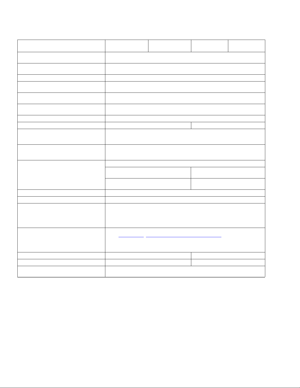
Table 1 Drive specifications summary for 3TB, 2TB, 1TB and 500GB models
Drive Specification*
ST3000DM008 &
ST3000DM009
ST2000DM006 &
ST2000DM007
ST1000DM010 ST500DM009
Formatted capacity (512 bytes/sector)** 3000GB (3TB); 2000GB (2TB); 1000GB (1TB); 500GB
Guaranteed sectors 5,860,533,168; 3,907,029,168; 1,953,525,168; 976,773,168
Heads 6 6 / 4 2 2/1
Disks 3 3 / 2 1 1
Bytes per sector
(4K physical emulated at 512-byte sectors)
4096
Default sectors per track 63
Default read/write heads 16
Default cylinders 16,383
Recording density (max) 1807kFCI
Track density (avg) 352ktracks/in
Areal density (avg) 625Gb/in
2
Spindle speed 7200 RPM
Internal data transfer rate (max) 2147Mb/s
Average data rate, read/write (MB/s) 156MB/s
Maximum sustained data rate, OD read (MB/s) 210MB/s
I/O data-transfer rate (max) 600MB/s
Cache buffer 64MB 32 MB
Height (max) 26.1mm / 1.028 in 20.20mm / 0.795 in
Width (max) 101.6mm /4.0 in (+
0.010 in)
Length (max) 146.99mm / 5.787 in
Weight (typical)
626g /1.38 lb
626g/1.38lb
535g / 1.18 lb
400g / 0.88lb
Average latency 4.16ms
Power-on to ready (typical) <10.0s
Power-on to ready (max) <17.0s <10.0s <8.5s
Standby to ready (max) <17.0s <10.0s <8.5s
Average seek, read (typical)
Average seek, write (typical)
<8.5ms
<9.5ms
Startup current 12V 2.0A or 2.5A 2.0A
Voltage tolerance (including noise) 5V: ±5%
12V: +10% / -7.5%
Non-Operating ambient temperature (°C) –40° to 70°
Operating ambient temperature (min °C) 0°
Operating temperature (Drive case max °C)
60°
†
Seagate BarraCuda Product Manual, Rev. F 9
www.seagate.com Drive Specifications
* All specifications above are based on native configurations.
** One GB equals one billion bytes and 1TB equals one trillion bytes when referring to hard drive capacity.
Accessible capacity may vary depending on operating environment and formatting.
*** During periods of drive idle, some offline activity may occur according to the S.M.A.R.T.
specification, which may increase acoustic and power to operational levels.
† Seagate does not recommend operating at sustained case temperatures above 60°C.
Operating at higher temperatures will reduce useful life of the product.
Temperature gradient 20°C per hour max (operating)
30°C per hour max (non-operating)
Relative humidity 5% to 95% (operating)
5% to 95% (non-operating)
Relative humidity gradient (max) 30% per hour
Wet bulb temperature (max) 26°C max (operating)
29°C max (non-operating)
Altitude, operating –304.8m to 3048m
(–1000 ft to 10,000+ ft)
Altitude, non-operating
(below mean sea level, max)
–304.8m to 12,192m
(–1000 ft to 40,000+ ft)
Operational shock (max) 80 Gs at 2ms
Non-operational shock (max) 300 Gs at 2ms 350 Gs at 2ms
Vibration, operating 2Hz to 22Hz: 0.25 Gs, Limited displacement
22Hz to 350Hz: 0.50 Gs
350Hz to 500Hz: 0.25 Gs
Vibration, non-operating 5Hz to 22Hz: 3.0 Gs
22Hz to 350Hz: 3.0 Gs
350Hz to 500Hz: 3.0 Gs
Drive acoustics, sound power
Idle*** 2.4 bels (typical)
2.6 bels (max)
2.2 bels (typical)
2.3 bels (max)
Seek 2.6 bels (typical)
2.7 bels (max)
2.3 bels (typical)
2.4 bels (max)
Non-recoverable read errors 1 per 10
14
bits read
Annualized Failure Rate (AFR) <1.0% based on 2400 POH
Rated Workload Average annualized workload rating: <55 TB/year.
The AFR specification for the product assumes the I/O workload does not exceed the average
annualized workload rate limit of 55 TB/year. Workloads exceeding the annualized rate may
degrade the product AFR and impact reliability as experienced by the particular application.
The average annualized workload rate limit is in units of TB per calendar year.
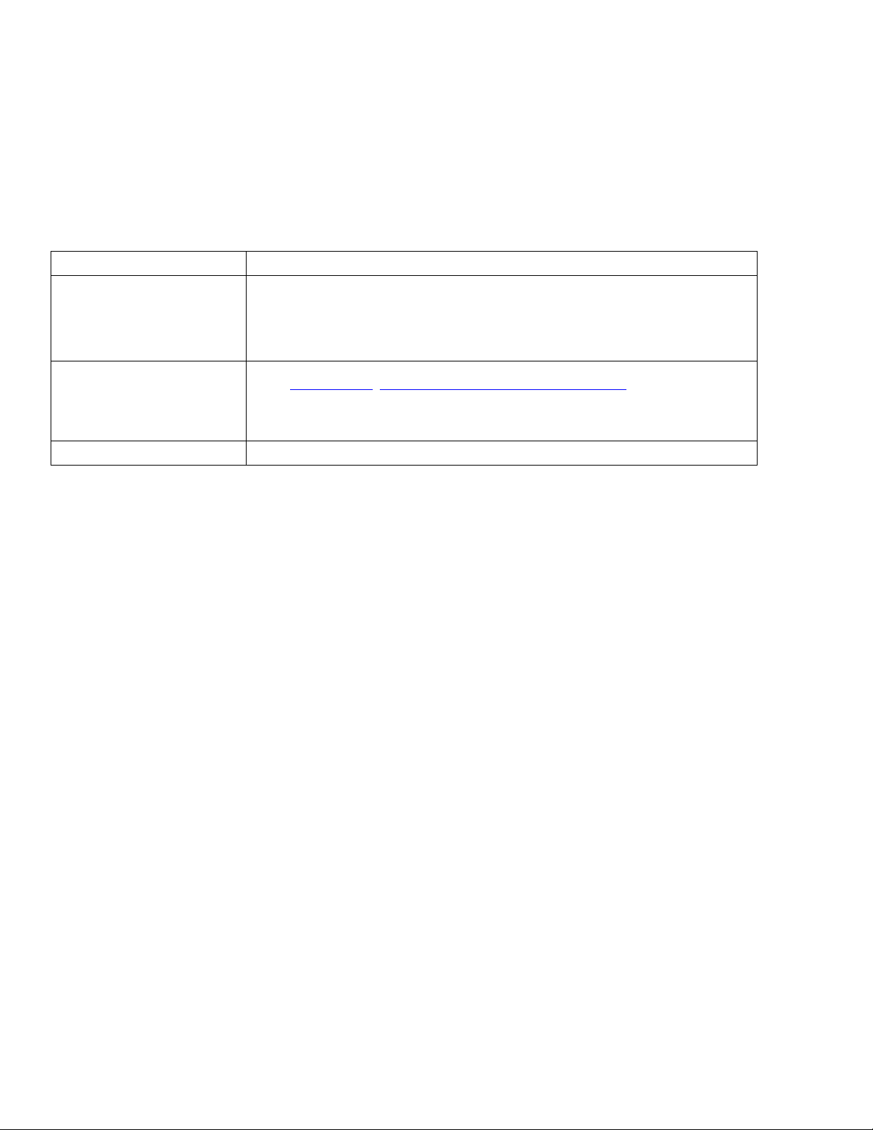
Warranty To determine the warranty for a specific drive, use a web browser to access the following web
page: http://www.sea
gate.com/support/warranty-and-replacements/
From this page, click on “Is my Drive under Warranty”. Users will be asked to provide the drive
serial number, model number (or part number) and country of purchase. The system will
display the warranty information for the drive.
Load/Unload cycles (25°C, 50% rel. humidity) 300,000 ----
Contact start-stop cycles (25°C, 50% rel. humidity) ---- 50,000
Supports Hotplug operation per the
Serial ATA Revision 3.2 specification
Yes
Table 1 Drive specifications summary for 3TB, 2TB, 1TB and 500GB models (continued)
Drive Specification*
ST3000DM008 &
ST3000DM009
ST2000DM006 &
ST2000DM007
ST1000DM010 ST500DM009
Seagate BarraCuda Product Manual, Rev. F 10
www.seagate.com Drive Specifications
2.2 Formatted capacity
*One GB equals one billion bytes and 1TB equals one trillion bytes when referring to hard drive capacity. Accessible capacity may vary depending on operating
environment and formatting.
2.2.1 LBA mode
When addressing these drives in LBA mode, all blocks (sectors) are consecutively numbered from 0 to n–1, where n is the number of
guaranteed sectors as defined above.
See Section 5.3.1, "Identify Device command" (words 60-61 and 100-103) for additional information about 48-bit addressing
support of drives with capacities over 137GB.
2.3 Default logical geometry
• Cylinders: 16,383
• Read/write heads: 16
• Sectors per track: 63
LBA mode
When addressing these drives in LBA mode, all blocks (sectors) are consecutively numbered from 0 to n–1, where n is the number of
guaranteed sectors as defined above.
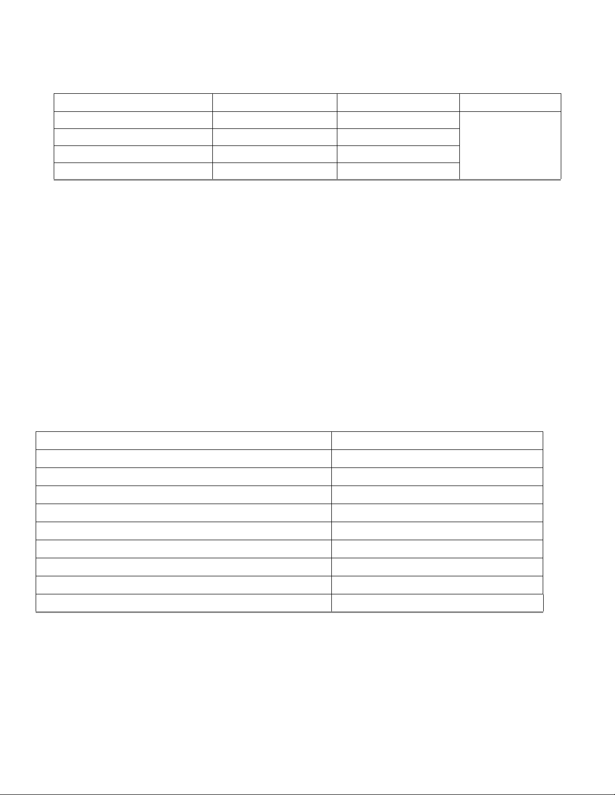
2.4 Recording and interface technology
Model Formatted capacity* Guaranteed sectors Bytes per sector
ST3000DM008 & ST3000DM009 3000GB 5,860,533,168
4096
ST2000DM006 & ST2000DM007 2000GB 3,907,029,168
ST1000DM010 1000GB 1,953,525,168
ST500DM009 500GB 976,773,168
Interface SATA
Recording method TGMR
Recording density (kFCI) 1807
Track density (ktracks/inch avg) 352
Areal density (Gb/in
2
)625
Spindle speed (RPM) 7200 ± 0.2%
Internal data transfer rate (Mb/s max) 2147
Maximum sustained data transfer rate, OD read (MB/s) 210
Average data rate, read/write (MB/s) 156
I/O data-transfer rate (MB/s max) 600
Seagate BarraCuda Product Manual, Rev. F 11
www.seagate.com Drive Specifications
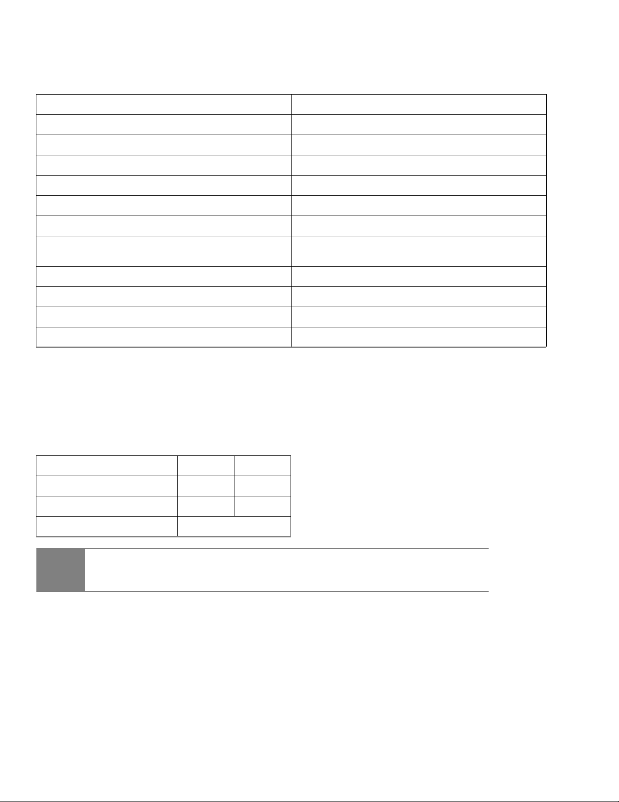
2.5 Physical characteristics
2.6 Seek time
Seek measurements are taken with nominal power at 25°C ambient temperature. All times are measured using drive diagnostics.
The specifications in the table below are defined as follows:
• Track-to-track seek time is an average of all possible single-track seeks in both directions.
• Average seek time is a true statistical random average of at least 5000 measurements of seeks between random tracks, less
overhead.
Maximum height
3TB and 2TB 26.1mm / 1.028 in
1TB and 500GB 20.20mm / 0.795 in
Maximum width (all models) 101.6mm / 4.0 in (± 0.010 in)
Maximum length (all models) 146.99mm / 5.787 in
Typical weight
3TB 626g / 1.38 lb
2TB
626g / 1.38 lb - or -
535g / 1.18 lb
1TB and 500GB 400g / 0.88lb
Cache buffer
3TB, 2TB and 1TB 64MB
500GB 32MB
Typical seek times (ms) Read Write
Track-to-track 1.0 1.2
Average 8.5 9.5
Average latency 4.16
Note
These drives are designed to consistently meet the seek times represented in this manual. Physical seeks,
regardless of mode (such as track-to-track and average), are expected to meet the noted values. However,
due to the manner in which these drives are formatted, benchmark tests that include command overhead
or measure logical seeks may produce results that vary from these specifications.
Seagate BarraCuda Product Manual, Rev. F 12
www.seagate.com Drive Specifications
2.7 Start/stop times
Time-to-ready may be longer than normal if the drive power is removed without going through normal OS powerdown
procedures.
2.8 Power specifications
The drive receives DC power (+5V or +12V) through a native SATA power connector. Refer to Figure 2 on page 23.
2.8.1 Power consumption
Power requirements for the drives are listed in Table 2 and Table 3. Typical power measurements are based on an average of drives
tested, under nominal conditions, using 5.0V and 12.0V input voltage at 25°C ambient temperature.
• Spinup power
Spinup power is measured from the time of power-on to the time that the drive spindle reaches operating speed.
• Read/write power and current
Read/write power is measured with the heads on track, based on a 16-sector write followed by a 32-ms delay, then a 16-sector
read followed by a 32-ms delay.
• Operating power and current
Operating power is measured using 40 percent random seeks, 40 percent read/write mode (1 write for each 10 reads) and 20
percent drive idle mode.
• Idle mode power
Idle mode power is measured with the drive up to speed, with servo electronics active and with the heads in a random track
location.
•Standby mode
During Standby mode, the drive accepts commands, but the drive is not spinning, and the servo and read/write electronics are
in power-down mode.
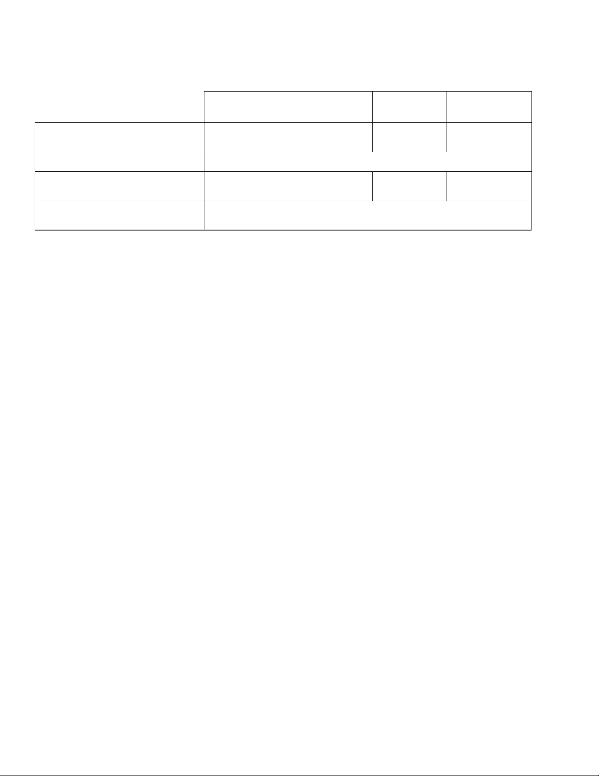
3-disk
(3TB models)
2-disk
(2TB models)
1-disk
(1TB models)
1-disk
(500GB models)
Power-on to ready (in seconds)
15 (typical)
17 (max)
10 (typical)
12 (max)
8.5 (typical)
10 (max)
Power-on to ready (typical) <10
Standby to ready (in seconds)
15 (typical)
17 (max)
10 (typical)
12 (max)
8.5 (typical)
10 (max)
Ready to spindle stop (in seconds)
10 (typical)
11 (max)
Seagate BarraCuda Product Manual, Rev. F 13
www.seagate.com Drive Specifications
*During periods of drive idle, some offline activity may occur according to the S.M.A.R.T. specification, which may increase acoustic and power to operational levels.
†5W IDLE with DIPLM Enabled
2.8.2 Conducted noise
Input noise ripple is measured at the host system power supply across an equivalent 80-ohm resistive load on the +12 volt line or
an equivalent 15-ohm resistive load on the +5 volt line.
• Using 12-volt power, the drive is expected to operate with a maximum of 120 mV peak-to-peak square-wave injected noise at up
to 10MHz.
• Using 5-volt power, the drive is expected to operate with a maximum of 100 mV peak-to-peak square-wave injected noise at up
to 10MHz.
2.8.3 Voltage tolerance
Voltage tolerance (including noise):
•5V ±5%
•12V +10% / -7.5%
Table 2 DC power requirements (3-disk: 3TB and 2TB models)
Power dissipation (3-disk values shown) Avg (watts 25° C) Avg 5V typ amps Avg 12V amps
Spinup — — 2.0A or 2.5A
Idle2* † 5.40 0.190 0.377
Operating 8.00 0.510 0.462
Standby 0.75 0.136 0.005
Sleep 0.75 0.136 0.005
Table 3 DC power requirements (1-disk: 1TB and 500GB models)
Power dissipation (1-disk values shown) Avg (watts 25° C) Avg 5V typ amps Avg 12V typ amps
Spinup — — 2.0
Perf Idle* † 4.6 0.378 0.224
Operating 5.3 0.656 0.243
Standby 0.94 0.350 0.010
Sleep 0.94 0.350 0.010
Note
Equivalent resistance is calculated by dividing the nominal voltage by the typical RMS read/write current.
Seagate BarraCuda Product Manual, Rev. F 14
www.seagate.com Drive Specifications
2.8.4 Power-management modes
The drive provides programmable power management to provide greater energy efficiency. In most systems, users can control
power management through the system setup program. The drive features the following power-management modes:
•Active mode
The drive is in Active mode during the read/write and seek operations.
• Idle mode
The buffer remains enabled, and the drive accepts all commands and returns to Active mode any time disk access is necessary.
•Standby mode
The drive enters Standby mode when the host sends a Standby Immediate command. If the host has set the standby timer, the
drive can also enter Standby mode automatically after the drive has been inactive for a specifiable length of time. The standby
timer delay is established using a Standby or Idle command. In Standby mode, the drive buffer is enabled, the heads are parked
and the spindle is at rest. The drive accepts all commands and returns to Active mode any time disk access is necessary.
•Sleep mode
The drive enters Sleep mode after receiving a Sleep command from the host. In Sleep mode, the drive buffer is disabled, the
heads are parked and the spindle is at rest. The drive leaves Sleep mode after it receives a Hard Reset or Soft Reset from the host.
After receiving a reset, the drive exits Sleep mode and enters Standby mode with all current translation parameters intact.
• Idle and Standby timers
Each time the drive performs an Active function (read, write or seek), the standby timer is reinitialized and begins counting
down from its specified delay times to zero. If the standby timer reaches zero before any drive activity is required, the drive
makes a transition to Standby mode. In both Idle and Standby mode, the drive accepts all commands and returns to Active
mode when disk access is necessary.
Power modes Heads Spindle Buffer
Active Tracking Rotating Enabled
Idle Tracking Rotating Enabled
Standby Parked Stopped Enabled
Sleep Parked Stopped Disabled
Seagate BarraCuda Product Manual, Rev. F 15
www.seagate.com Drive Specifications
2.9 Environmental specifications
This section provides the temperature, humidity, shock, and vibration specifications. Ambient temperature is defined as the
temperature of the environment immediately surrounding the drive. Above 1000ft. (305 meters), the maximum temperature is
derated linearly by 1°C every 1000 ft.
Refer to
Section 3.4 Drive mounting for base plate measurement location.
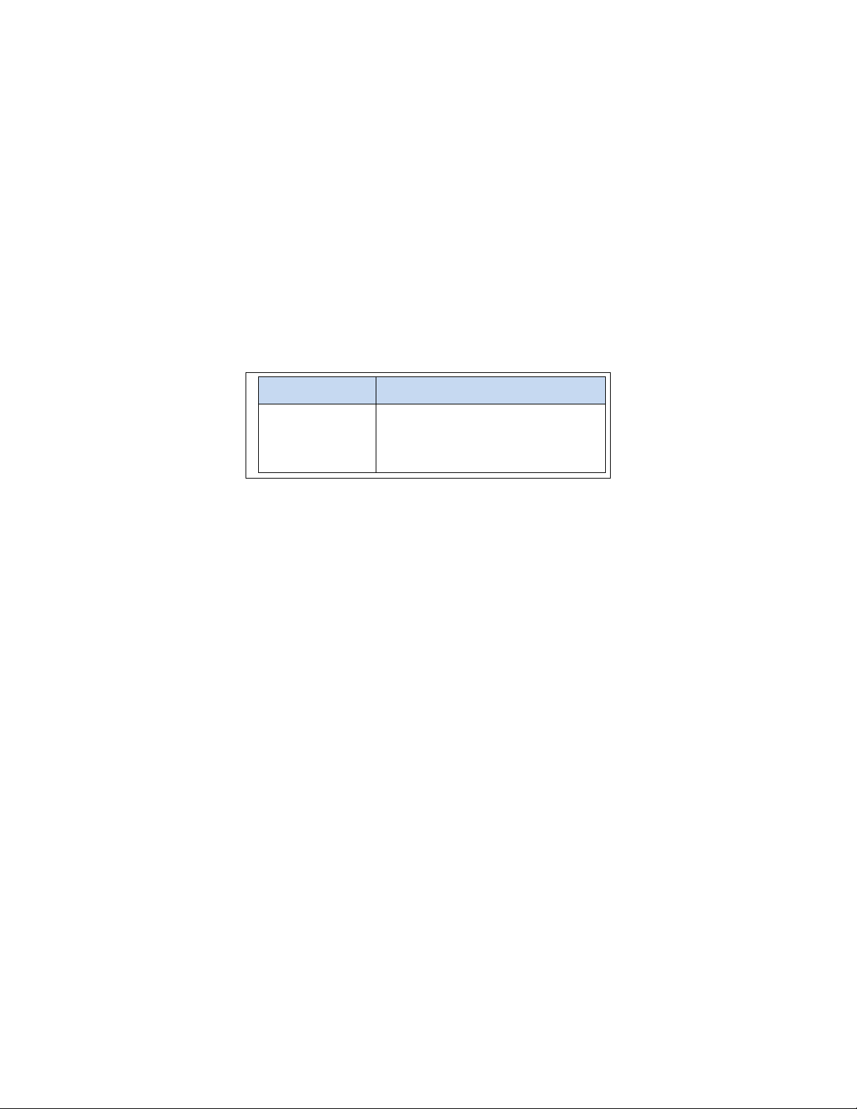
2.9.1 Ambient temperature
† Seagate does not recommend operating at sustained case temperatures above 60°C.
Operating at higher temperatures will reduce useful life of the product.
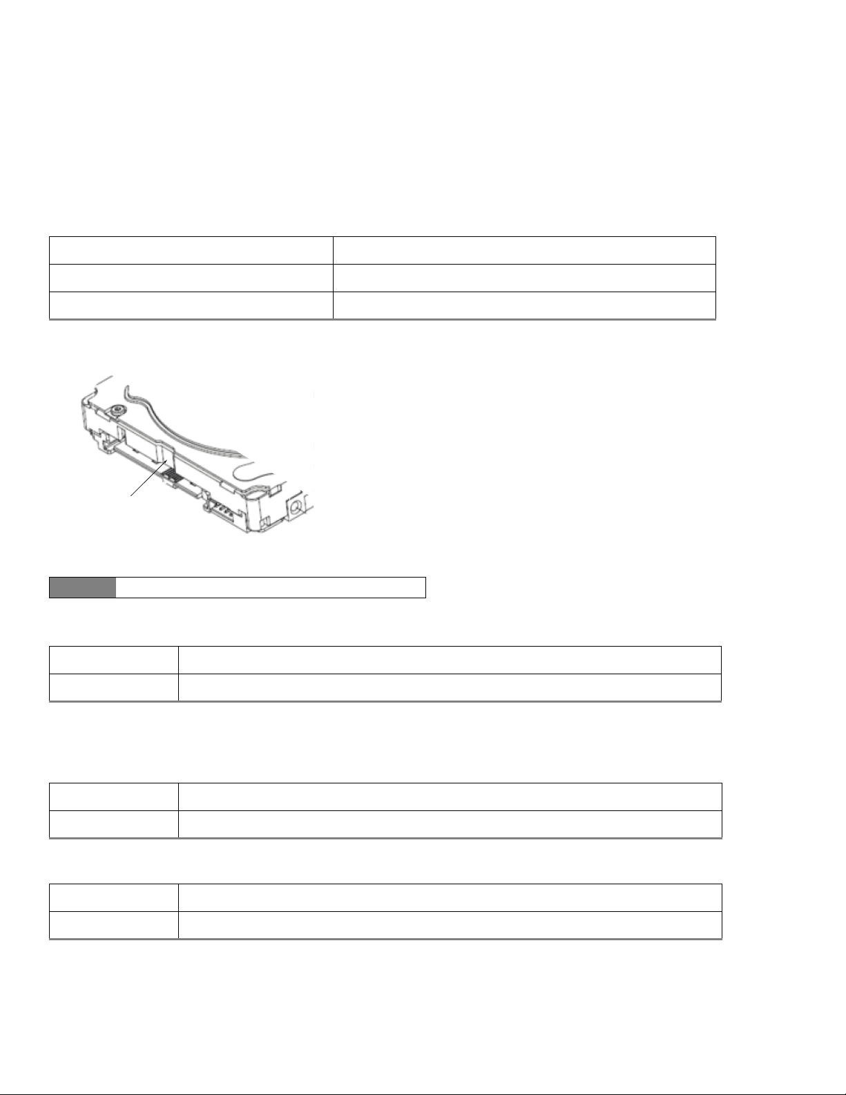
Figure 1 Location of the HDA temperature check point
2.9.2 Temperature gradient
2.9.3 Humidity
2.9.3.1 Relative humidity
2.9.3.2 Wet bulb temperature
Non-Operating ambient temperature (°C) –40° to 70°
Operating ambient temperature (min °C) 0°
Operating temperature (Drive case max °C) 60°
†
Note Image is for reference only, may not represent actual drive.
Operating 20°C per hour (68°F per hour max), without condensation
Non-operating 30°C per hour (86°F per hour max)
Operating 5% to 95% non-condensing (30% per hour max)
Non-operating 5% to 95% non-condensing (30% per hour max)
Operating 26°C / 78.8°F (rated)
Non-operating 29°C / 84.2°F (rated)
HDA Temp.
Check Point
Seagate BarraCuda Product Manual, Rev. F 16
www.seagate.com Drive Specifications
2.9.4 Altitude
2.9.5 Shock and Vibration
All shock specifications assume that the drive is mounted securely with the input shock applied at the drive mounting screws.
Shock may be applied in the X, Y or Z axis.
2.9.5.1 Operating shock
These drives comply with the performance levels specified in this document when subjected to a maximum operating shock of 80
Gs based on half-sine shock pulses of 2 ms during read operations. Shocks should not be repeated more than two times per second.
2.9.5.2 Non-operating shock
3TB and 2TB models
The non-operating shock level that the drive can experience without incurring physical damage or degradation in performance
when subsequently put into operation is 300 Gs based on a non-repetitive half-sine shock pulse of 2 ms duration.
1TB and 500GB models
The non-operating shock level that the drive can experience without incurring physical damage or degradation in performance
when subsequently put into operation is 350 Gs based on a non-repetitive half-sine shock pulse of 2-ms duration.
2.9.5.3 Operating vibration
The maximum vibration levels that the drive may experience while meeting the performance standards specified in this document
are specified below.
All vibration specifications assume that the drive is mounted securely with the input vibration applied at the drive mounting
screws. Vibration may be applied in the X, Y or Z axis. Throughput may vary if improperly mounted.
2.9.6 Non-operating vibration
The maximum non-operating vibration levels that the drive may experience without incurring physical damage or degradation in
performance when subsequently put into operation are specified below.
Operating –304.8m to 3048m (–1000 ft. to 10,000+ ft.)
Non-operating –304.8m to 12,192m (–1000 ft. to 40,000+ ft.)
2Hz to 22Hz 0.25 Gs (Limited displacement)
22Hz to 350Hz 0.50 Gs
350Hz to 500Hz 0.25 Gs
5Hz to 22Hz 3.0 Gs (Limited displacement)
22Hz to 350Hz 3.0 Gs
350Hz to 500Hz 3.0 Gs
Seagate BarraCuda Product Manual, Rev. F 17
www.seagate.com Drive Specifications
2.10 Acoustics
Drive acoustics are measured as overall A-weighted acoustic sound power levels (no pure tones). All measurements are consistent
with ISO document 7779. Sound power measurements are taken under essentially free-field conditions over a reflecting plane. For
all tests, the drive is oriented with the cover facing upward.
*During periods of drive idle, some offline activity may occur according to the S.M.A.R.T. specification, which may increase acoustic and power to operational levels.
2.10.1 Test for Prominent Discrete Tones (PDTs)
Seagate follows the ECMA-74 standards for measurement and identification of PDTs. An exception to this process is the use of the
absolute threshold of hearing. Seagate uses this threshold curve (originated in ISO 389-7) to discern tone audibility and to
compensate for the inaudible components of sound prior to computation of tone ratios according to Annex D of the ECMA-74
standards.
2.11 Electromagnetic immunity
When properly installed in a representative host system, the drive operates without errors or degradation in performance when
subjected to the radio frequency (RF) environments defined in
Table 5.
Note
For seek mode tests, the drive is placed in seek mode only.
The number of seeks per second is defined by the following equation:
(Number of seeks per second = 0.4 / (average latency + average access time
Table 4 Fluid Dynamic Bearing (FDB) motor acoustics
Idle* Seek
3 Disks
(3TB, 2TB)
2.4 bels (typical)
2.6 bels (max)
2.6 bels (typical)
2.7 bels (max)
2 Disks
(2TB)
1 Disk
(1TB and 500GB)
2.2 bels (typical)
2.4 bels (max)
2.4 bels (typical)
2.5 bels (max)
Table 5 Radio frequency environments
Tes t Des cripti on
Performance
level
Reference
standard
Electrostatic discharge Contact, HCP, VCP: ± 4 kV; Air: ± 8 kV B EN61000-4-2: 95
Radiated RF immunity 80MHz to 1,000MHz, 3 V/m,
80% AM with 1kHz sine
900MHz, 3 V/m, 50% pulse modulation @ 200Hz
A EN61000-4-3: 96
ENV50204: 95
Electrical fast transient ± 1 kV on AC mains, ± 0.5 kV on external I/O B EN61000-4-4: 95
Surge immunity ± 1 kV differential, ± 2 kV common,
AC mains
B EN61000-4-5: 95
Conducted RF immunity 150kHz to 80MHz, 3 Vrms, 80% AM with 1kHz sine A EN61000-4-6: 97
Voltage dips, interrupts 0% open, 5 seconds
0% short, 5 seconds
40%, 0.10 seconds
70%, 0.01 seconds
C
C
C
B
EN61000-4-11: 94
Seagate BarraCuda Product Manual, Rev. F 18
www.seagate.com Drive Specifications
2.12 Reliability
2.12.1 Annualized Failure Rate (AFR)
The production disk drive shall achieve an annualized failure-rate of <1.0% over a 5 year service life when used in Desktop Storage
field conditions as limited by the following:
• 2400 power-on-hours per year.
• Typical workload
2.12.2 Storage
Maximum storage periods are 180 days within original unopened Seagate shipping package or 60 days unpackaged within the
defined non-operating limits (refer to environmental section in this manual). Storage can be extended to 1 year packaged or
unpackaged under optimal environmental conditions (25°C, <40% relative humidity non-condensing, and non-corrosive
environment). During any storage period the drive non-operational temperature, humidity, wet bulb, atmospheric conditions,
shock, vibration, magnetic and electrical field specifications should be followed.
2.13 Agency and Safety Certifications
Each Hard Drive and Solid State Drive ("drives") has a product label that includes certifications that are applicable to that specific
drive. The following information provides an overview of requirements that may be applicable to the drive.
2.13.1 Safety certification
The drives are recognized in accordance with UL/cUL 60950-1 and EN 60950-1.
2.13.2 European Union (EU) CE Marking Requirements
Drives that display the CE mark comply with the European Union (EU) requirements specified in the Electromagnetic Compatibility
Directive (2014/30/EU) put into force on 20 April 2016. Testing is performed to the levels specified by the product standards for
Information Technology Equipment (ITE). Emission levels are defined by EN 55032:2012, Class B and the immunity levels are
defined by EN 55024:2010.
The drives also meet the requirements of The Low Voltage Directive (LVD) 2014/35/EU.
Seagate drives are tested in representative end-user systems. Although CE-marked Seagate drives comply with all relevant
regulatory requirements and standards for the drives, Seagate cannot guarantee that all system-level products into which the
drives are installed comply with all regulatory requirements and standards applicable to the system-level products. The drive is
designed for operation inside a properly designed system (e.g., enclosure designed for the drive), with properly shielded I/O cable
(if necessary) and terminators on all unused I/O ports. Computer manufacturers and system integrators should confirm EMC
compliance and provide CE marking for the system-level products.
For compliance with the RoHS "Recast" Directive 2011/65/EU (RoHS 2), See Section 2.14.1 on page 20 .
Nonrecoverable read errors 1 per 10
14
bits read, max
Rated Workload Average annualized workload rating: <55 TB/year.
The AFR specification for the product assumes the I/O workload does not exceed the average
annualized workload rate limit of 55 TB/year. Workloads exceeding the annualized rate may
degrade the product AFR and impact reliability as experienced by the particular application.
The average annualized workload rate limit is in units of TB per calendar year.
Warranty
To determine the warranty for a specific drive, use a web browser to access the following web
page: http://www.seagate.com/support/warranty-and-replacements/.
From this page, click on the “Is my Drive under Warranty” link. The following are required to
be provided: the drive serial number, model number (or part number) and country of
purchase. The system will display the warranty information for the drive.
Preventive maintenance None required.
Seagate BarraCuda Product Manual, Rev. F 19
www.seagate.com Drive Specifications
2.13.3 Australian RCM Compliance Mark
If these models have the RCM marking, they comply with the Australia/New Zealand Standard AS/NZ CISPR32 and meet the
Electromagnetic Compatibility (EMC) Framework requirements of the Australian Communication and Media Authority (ACMA).
2.13.4 Canada ICES-003
If this model has the ICES-003:2016 marking it complies with requirements of ICES tested per ANSI C63.4-2014.
2.13.5 South Korean KC Certification Mark
The South Korean KC Certification Mark means the drives comply with paragraph 1 of Article 11 of the Electromagnetic
Compatibility control Regulation and meet the Electromagnetic Compatibility (EMC) Framework requirements of the Radio
Research Agency (RRA) Communications Commission, Republic of Korea.These drives have been tested and comply with the
Electromagnetic Interference/Electromagnetic Susceptibility (EMI/EMS) for Class B products. Drives are tested in a representative,
end-user system by a Korean-recognized lab.
2.13.6 Morocco Commodity Mark
To satisfy our OEM customers, Seagate has added the Moroccan Commodity Mark to the drives provided to the OEM for the sale of
Customer Kits produced by our OEM customers that are intended to be incorporated into the OEM's finished system-level product
by an end user. The Customer Kits are considered 'devices' under Morocco's Order of the Minister of Industry, Trade, Investment and
Digital Economy No. 2574-14 of 29 Ramadan 1436 (16 July 2015) on electromagnetic compatibility of equipment.
Seagate drives are tested for compliance and complies with the European Union (EU) Electromagnetic Compatibility (EMC)
Directive 2014/30/EU and the Low Voltage Directive (LVD) 2014/35/EU. Accordingly, the drives also meets the requirements of
Morocco's Order of the Minister of Industry, Trade, Investment and Digital Economy No. 2574-14 of 29 Ramadan 1436 (16 July 2015)
on electromagnetic compatibility of equipment.
2.13.7 Taiwanese BSMI
Drives with the Taiwanese certification mark comply with Chinese National Standard, CNS13438.
For compliance with the Taiwan Bureau of Standards, Metrology and Inspection’s (BSMI) requirements,
See Section 2.14.3 on page 22 .
ࣗط یࡈ߇ΰח
%
ɼࢽࡈ؏ܞݦࢢ
ࢇ Е ɼࢽࡈ% ࢷળࢶଢԻ۰ ࣯Ի
ɼࢽ߾۰ یࡈଜЕ ʨࡶ ּࢶࡳԻ ଜֲ ֻҘ
ࠇ߾۰یࡈଟܹݡТЬ

Seagate BarraCuda Product Manual, Rev. F 20
www.seagate.com Drive Specifications
2.13.8 FCC verification
These drives are intended to be contained solely within a personal computer or similar enclosure (not attached as an external
device). As such, each drive is considered to be a subassembly even when it is individually marketed to the customer. As a
subassembly, no Federal Communications Commission verification or certification of the device is required.
Seagate has tested this device in enclosures as described above to ensure that the total assembly (enclosure, disk drive,
motherboard, power supply, etc.) does comply with the limits for a Class B computing device, pursuant to Subpart J, Part 15 of the
FCC rules. Operation with noncertified assemblies is likely to result in interference to radio and television reception.
Radio and television interference. This equipment generates and uses radio frequency energy and if not installed and used in
strict accordance with the manufacturer’s instructions, may cause interference to radio and television reception.
This equipment is designed to provide reasonable protection against such interference in a residential installation. However, there
is no guarantee that interference will not occur in a particular installation. If this equipment does cause interference to radio or
television, which can be determined by turning the equipment on and off, users are encouraged to try one or more of the following
corrective measures:
• Reorient the receiving antenna.
• Move the device to one side or the other of the radio or TV.
• Move the device farther away from the radio or TV.
• Plug the computer into a different outlet so that the receiver and computer are on different branch outlets.
If necessary, users should consult a dealer or an experienced radio/television technician for additional suggestions. Users may find
helpful the following booklet prepared by the Federal Communications Commission: How to Identify and Resolve Radio-Television
Interference Problems. This booklet is available from the Superintendent of Documents, U.S. Government Printing Office,
Washington, DC 20402. Refer to publication number 004-000-00345-4.
2.14 Environmental protection
Seagate designs its products to meet environmental protection requirements worldwide, including regulations restricting certain
chemical substances.
2.14.1 European Union Restriction of Hazardous Substance Law
2.14.1.1 Restriction of Hazardous Substances in Electrical and Electronic Equipment
Seagate drives are designed to be compliant with the European Union RoHS "Recast" Directive 2011/65/EU (RoHS 2) as amended by
Directive (EU) 2015/863. The RoHS2 restricts the use of certain hazardous substances such as Lead, Cadmium, Mercury, Hexavalent
Chromium, Polybrominated Biphenyls (PBB) and Polybrominated Diphenyl Ether (PBDE), BisBis(2-Ethylhexyl) phthalate (DEHP),
Benzyl butyl phthalate (BBP), Dibutyl phthalate (DBP), and Diisobutyl phthalate (DIBP) in electrical and electronic equipment (EEE).
Seagate BarraCuda Product Manual, Rev. F 21
www.seagate.com Drive Specifications
2.14.1.2 Substances of Very High Concern (SVHC)
The European Union REACH (Registration, Evaluation, Authorization and Restriction of Chemicals) Regulation (EC) 1907/2006
regulates chemicals shipped into and used in Europe. A number of parts and materials in Seagate products are procured from
external suppliers. We rely on the representations of our suppliers regarding the presence of REACH substances in these articles
and materials. Our supplier contracts require compliance with our chemical substance restrictions, and our suppliers document
their compliance with our requirements by providing full-disclosure material content declarations that disclose inclusion of any
REACH-regulated substance in such articles or materials. Product-specific REACH declarations are available upon request through
your Seagate Sales Representative.
2.14.2 China Requirements —China RoHS 2
China RoHS 2 refers to the Ministry of Industry and Information Technology Order No. 32, effective July 1, 2016, titled
Management Methods for the Restriction of the Use of Hazardous Substances in Electrical and Electronic Products.
To comply with China RoHS 2, Seagate determines this product's Environmental Protection Use Period (EPUP) to be
20 years in accordance with the Marking for the Restricted Use of Hazardous Substances in Electronic and Electrical
Products, SJT 11364-2014.
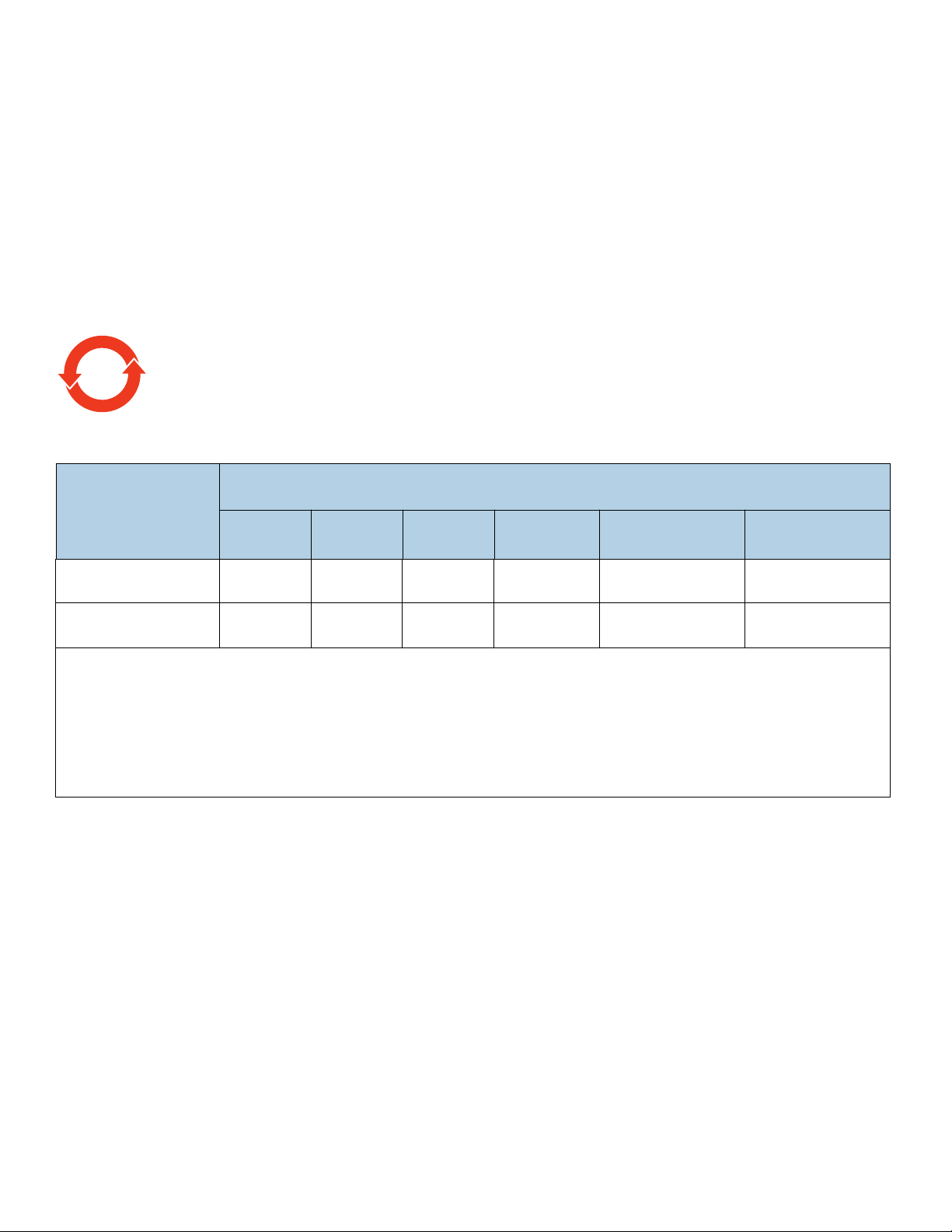
Table 6 China - Hazardous Substances
部件名称
Part Name
有害物质
Hazardous Substances
铅
(Pb)
汞
(Hg)
镉
(Cd)
六价铬
(Cr
+6
)
多溴联苯
(PBB)
多溴二苯醚
(PBDE)
硬盘驱动器
HDD
XOO O O O
印刷电路板组装
PCBA
XOO O O O
本表格依据 SJ/T 11364 的规定编制。
This table is prepared in accordance with the provisions of SJ/T 11364-2014
O:表示该有害物质在该部件所有均质材料中的含量均在 GB/T 26572 规定的限量要求以下。
O:Indicates that the hazardous substance contained in all of the homogeneous materials for this
part is below the limit requirement of GB/T26572.
X:表示该有害物质至少在该部件的某一均质材料中的含量超出 GB/T 26572 规定的限量要求。
X:Indicates that the hazardous substance contained in at least one of the homogeneous materials
used for this part is above the limit requirement of GB/T26572.
20
Seagate BarraCuda Product Manual, Rev. F 22
www.seagate.com Drive Specifications
2.14.3 Taiwan Requirements — Taiwan RoHS
Taiwan RoHS refers to the Taiwan Bureau of Standards, Metrology and Inspection’s (BSMI) requirements in standard CNS 15663,
Guidance to reduction of the restricted chemical substances in electrical and electronic equipment. Seagate products must comply
with the “Marking of presence” requirements in Section 5 of CNS 15663, effective January 1, 2018. This product is Taiwan RoHS
compliant.
The following table meets the Section 5 “Marking of presence” requirements.
2.15 Corrosive environment
Seagate electronic drive components pass accelerated corrosion testing equivalent to 10 years exposure to light industrial
environments containing sulfurous gases, chlorine and nitric oxide, classes G and H per ASTM B845. However, this accelerated
testing cannot duplicate every potential application environment. Users should use caution exposing any electronic components
to uncontrolled chemical pollutants and corrosive chemicals as electronic drive component reliability can be affected by the
installation environment. The silver, copper, nickel and gold films used in Seagate products are especially sensitive to the presence
of sulfide, chloride, and nitrate contaminants. Sulfur is found to be the most damaging. In addition, electronic components should
never be exposed to condensing water on the surface of the printed circuit board assembly (PCBA) or exposed to an ambient
relative humidity greater than 95%. Materials used in cabinet fabrication, such as vulcanized rubber, that can outgas corrosive
compounds should be minimized or eliminated. The useful life of any electronic equipment may be extended by replacing
materials near circuitry with sulfide-free alternatives.
Table 7 Taiwan - Restricted Substances
設備名稱:硬盤設備,型號:僅適用于內部使用
Equipment Name: Hard Disk Device, Type Designation: Internal Use Only
單元
Unit
限用物質及其化學符號
Restricted Substance and its chemical symbol
鉛
(Pb)
汞
(Hg)
鎘
(Cd)
六價鉻
(Cr
+6
)
多溴聯苯
(PBB)
多溴二苯醚
(PBDE)
硬盤驅動器
HDD
—OOOOO
印刷電路板组装
PCBA
—OOOOO
備考 1. "O" 係指該项限用物質之百分比含量未超出百分比含量基準值。
Note 1. "O" indicates that the percentage content of the restricted substance
does not exceed the percentage of reference value of presence.
備考 2. "—" 係指該项限用物質為排除項目。
Note 2. "—" indicates that the restricted substance corresponds to the exemption.
Seagate BarraCuda Product Manual, Rev. F 23
www.seagate.com Configuring and Mounting the Drive
3.0 Configuring and Mounting the Drive
This section contains the specifications and instructions for configuring and mounting the drive.
3.1 Handling and static-discharge precautions
After unpacking, and before installation, the drive may be exposed to potential handling and electrostatic discharge (ESD) hazards.
Observe the following standard handling and static-discharge precautions:
Caution
• Before handling the drive, put on a grounded wrist strap, or ground oneself frequently by touching the metal chassis of a computer
that is plugged into a grounded outlet. Wear a grounded wrist strap throughout the entire installation procedure.
• Handle the drive by its edges or frame only.
• The drive is extremely fragile—handle it with care. Do not press down on the drive top cover.
• Always rest the drive on a padded, antistatic surface until mounting it in the computer.
• Do not touch the connector pins or the printed circuit board.
• Do not remove the factory-installed labels from the drive or cover them with additional labels. Removal voids the warranty. Some
factory-installed labels contain information needed to service the drive. Other labels are used to seal out dirt and contamination.
3.2 Configuring the drive
Each drive on the SATA interface connects point-to-point with the SATA host adapter. There is no master/slave relationship because
each drive is considered a master in a point-to-point relationship. If two drives are attached on one SATA host adapter, the host
operating system views the two devices as if they were both “masters” on two separate ports. Both drives behave as if they are
Device 0 (master) devices.
SATA drives are designed for easy installation. It is usually not necessary to set any jumpers on the drive for proper operation;
however, if users connect the drive and receive a “drive not detected” error, the SATA-equipped motherboard or host adapter may
use a chipset that does not support SATA speed autonegotiation.
3.3 SATA cables and connectors
The SATA interface cable consists of four conductors in two differential pairs, plus three ground connections. The cable size may be
30 to 26 AWG with a maximum length of one meter (39.37 inches). See
Table 8 for connector pin definitions. Either end of the SATA
signal cable can be attached to the drive or host.
For direct backplane connection, the drive connectors are inserted directly into the host receptacle. The drive and the host
receptacle incorporate features that enable the direct connection to be hot pluggable and blind mateable.
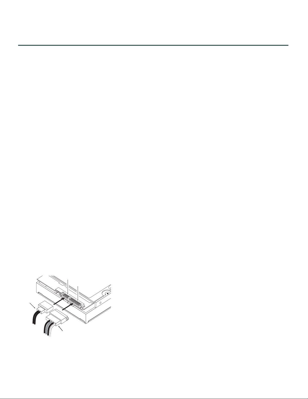
For installations which require cables, users can connect the drive as illustrated in
Figure 2.
Figure 2 Attaching SATA cabling
Each cable is keyed to ensure correct orientation. BarraCuda drives support latching SATA connectors.
Power cable
Signal cable
Signal connector
Power connector
Seagate BarraCuda Product Manual, Rev. F 24
www.seagate.com Configuring and Mounting the Drive
3.4 Drive mounting
Users can mount the drive in any orientation using four screws in the side-mounting holes or four screws in the bottom-mounting
holes. Refer to
Figure 3 through Figure 6 for drive mounting dimensions. Follow these important mounting precautions when
mounting the drive:
• Allow a minimum clearance of 0.030 inches (0.76mm) around the entire perimeter of the drive for cooling.
• Use only 6-32 UNC mounting screws.
• The screws should be inserted no more than 0.140 inch (3.56mm) into the bottom or side mounting holes.
• Do not overtighten the mounting screws (maximum torque: 6 inch-lb).
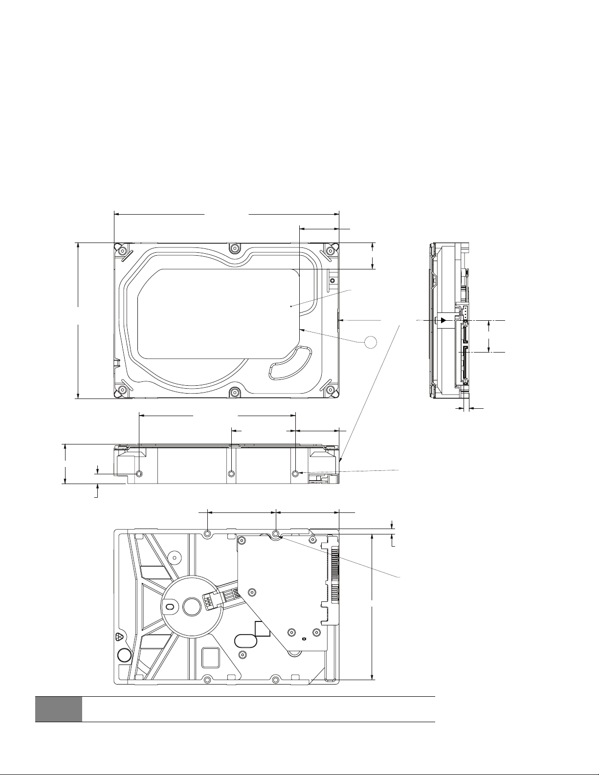
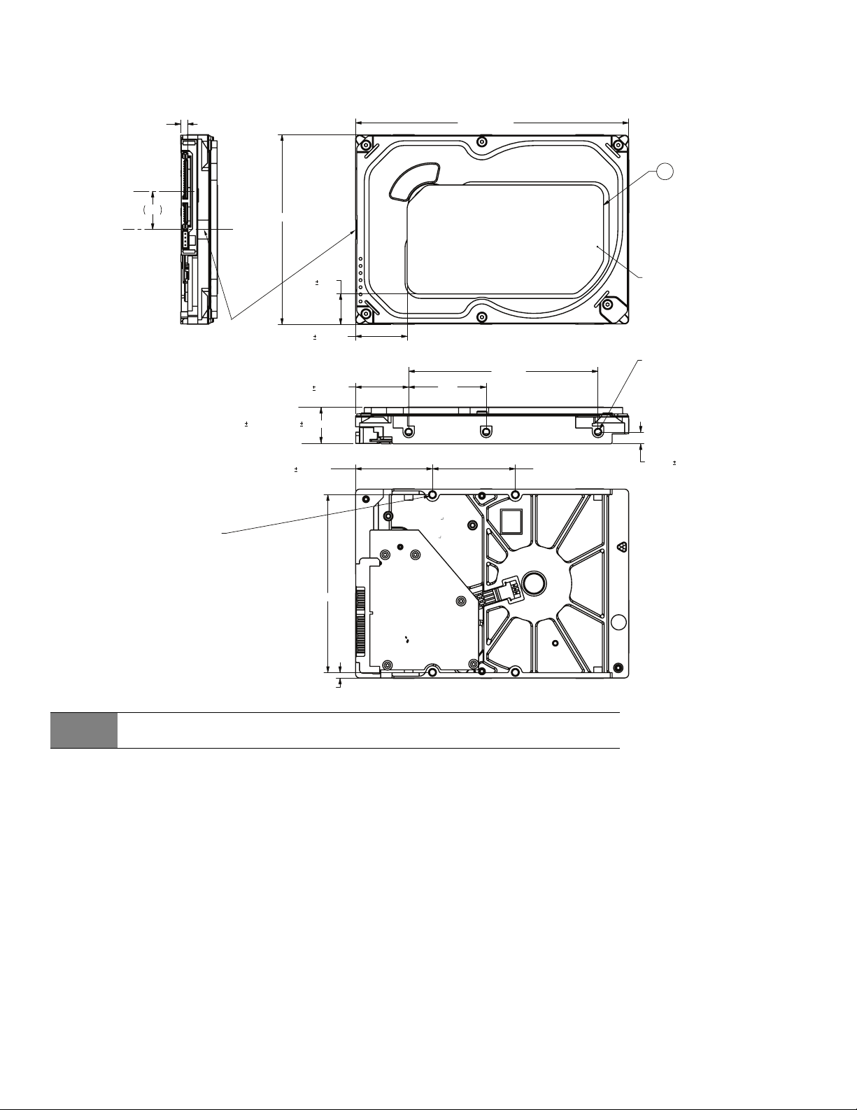
Figure 3 Mounting dimensions (2/3-disk: 2TB to 3TB models)
Note
Drawings are for mounting hole reference only.
PCBA show in pictorial only and can vary based on specific customer configurations.
TOP OF LABEL
5 TYP
3X 6-32 UNC-2B
3 MINIMUM THREAD DEPTH
0.1 MAXIMUM FASTENER
PENETRATION BOTH SIDES
4X 6-32 UNC-2B
3 MINIMUM THREAD DEPTH
0.1 MAXIMUM FASTENER
PENETRATION
C
L
OF DRIVE
C
L
OF CONNECTOR
DATUM B
5.787 in max
146.99 mm
4.010 in max
101.85 mm
2x 1.625 ± .020 in
41.28 ± .51 mm
2x 1.750 in
44.45 mm
2x 0.125 in
3.18 mm
4.00 in
101.60 mm
1.638 in
41.61 mm
1.122 ± .020 in
30.99 ± .51 mm
0.138 in
3.51 mm
0.814 in
20.68 mm
1.028 in max
26.11 mm
3x 0.250 ± .010 in
6.35 ± .25 mm
BOTH SIDES
2x 3.750 in
95.25 mm
1.013 ± .050 in
25.73 ± 1.27 mm
0.680 ± .050 in
17.27 ± 1.27 mm
Temperature
Check Point
Seagate BarraCuda Product Manual, Rev. F 25
www.seagate.com Configuring and Mounting the Drive
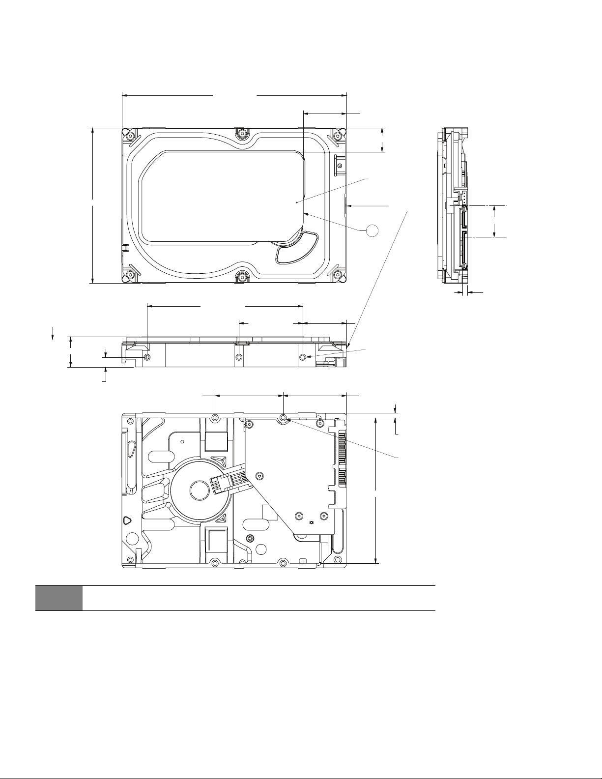
Seagate utilizes three base decks for 1TB and 500GB capacities, as shown below.
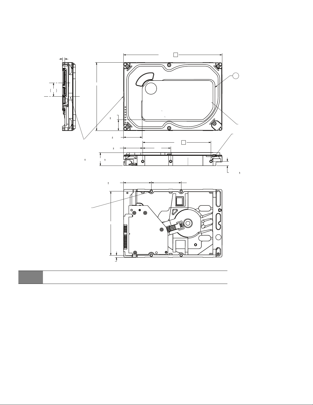
Figure 4 Mounting dimensions (configuration 1)
Note
Drawings are for mounting hole reference only.
PCBA show in pictorial only and can vary based on specific customer configurations.
5.787 MAX
3
4.010 MAX
.640
.050
1.090
.050
5
TOP OF LABEL
.814
.138
1.122
.020 1.638
4.000
3
3X .250
.010
BOTH SIDES
6X 6-32 UNC-2B
3 MINIMUM THREAD DEPTH
0.14 MAXIMUM FASTENER PENETRATION
MOUNTING HOLES BOTH SIDES
2X 1.625
.020
2X 1.750
2X 3.750
2X .125
4X 6-32 UNC-2B
3 MINIMUM THREAD DEPTH
0.14 MAXIMUM FASTENER PENETRATION
MOUNTING HOLES
C
L
OF CONNECTOR
DATUM B
C
L
OF DRIVE
TEMPERATURE
CHECKPOINT
Alterntive: .783" .012" or 19.90 0.30 mm
Max: .795" or 20.20 mm
Seagate BarraCuda Product Manual, Rev. F 26
www.seagate.com Configuring and Mounting the Drive
Figure 5 Mounting dimensions (configuration 2)
Note
Drawings are for mounting hole reference only.
PCBA show in pictorial only and can vary based on specific customer configurations.
5.787 MAX
4.010 MAX
1.090 .050
.640
.050
5
TOP OF LABEL
4.000
1.6381.122
.020
3X .250
.010
BOTH SIDES
3X 6-32 UNC-2B
3 MINIMUM THREAD DEPTH
0.1 MAXIMUM FASTENER PENETRATION
MOUNTING HOLES BOTH SIDES
.138
.814
2X 1.625
.020
2X 1.750
2X 3.750
2X .125
4X 6-32 UNC-2B
3 MINIMUM THREAD DEPTH
0.1 MAXIMUM FASTENER PENETRATION
MOUNTING HOLES
C
L
OF DRIVE
C
L
OF CONNECTOR
DATUM B
Temperature
Check Point
Max: .795" or 20.20 mm
Alterntive: .783" .012" or 19.90 0.30 mm
Seagate BarraCuda Product Manual, Rev. F 27
www.seagate.com Configuring and Mounting the Drive
Figure 6 Mounting dimensions (configuration 3)
Note
Drawings are for mounting hole reference only.
PCBA show in pictorial only and can vary based on specific customer configurations.
5 TYP
TOP OF LABEL
C
L
OF CONNECTOR
DATUM B
C
L
OF DRIVE
3X 6-32 UNC-2B
3 MINIMUM THREAD DEPTH
0.1 MAXIMUM FASTENER
PENETRATION BOTH SIDES
4X 6-32 UNC-2B
3 MINIMUM THREAD DEPTH
0.1 MAXIMUM FASTENER
PENETRATION
5.787 in. max
146.99 mm
4.010 in. max
101.85 mm
0.795 in. or
20.20 mm max
3x .250 ± .010in
6.35 ± .25mm
BOTH SIDES
4.00 in
101.60 mm
1.638 in
41.61 mm
1.122 ± .020 in
30.99 ± .51 mm
2x 1.625 ± .020 in
41.28 ± .51 mm
2x 1.750 in
44.45 mm
2x 3.750 in
95.25 mm
2x 0.125 in
3.18 mm
1.106 ± .050 in
28.09 ± 1.27 mm
0.626 ± .050 in
15.90 ± 1.27 mm
Temperature
Check Point
0.814 in
20.68 mm
0.138 in
3.51 mm
Alternative z-height
0.783 in. ± .012 in.
19.99 mm ± 0.30 mm

Seagate BarraCuda Product Manual, Rev. F 28
www.seagate.com About (SED) Self-Encrypting Drives
4.0 About (SED) Self-Encrypting Drives
Self-encrypting drives (SEDs) offer encryption and security services for the protection of stored data, commonly known as "data at
rest". These drives are compliant with the Trusted Computing Group (TCG) Opal Storage Specifications as detailed in the following:
• TCG Storage Architecture Core Specification, Version 2.0 (see www.trustedcomputin
ggroup.org)
• TCG Storage Security Subsystem Class Opal Specification, Version 2.0 (see www.trustedcomputin
ggroup.org)
In case of conflict between this document and any referenced document, this document takes precedence.
The Trusted Computing Group (TCG) is a standards organization sponsored and operated by companies in the computer, storage
and digital communications industry. Seagate's SED models comply with the standards published by the TCG.
To use the security features in the drive, the host must be capable of constructing and issuing the following two SATA commands:
•Trusted Send
•Trusted Receive
These commands are used to convey the TCG protocol to and from the drive in their command payloads. Seagate Secure SEDs also support TCG
Single User Mode, which can be disabled.
4.1 Data Encryption
Encrypting drives use one inline encryption engine within each drive employing AES-256 algorithms in Cipher Block Chaining (CBC) mode to
encrypt all data prior to being written on the media and to decrypt all data as it is read from the media. The encryption engine is always in
operation and cannot be disabled. The 32-byte Data Encryption Key (DEK) is a random number which is generated by the drive, never leaves the
drive, and is inaccessible to the host system. The DEK is itself encrypted when it is stored on the media and when in volatile temporary storage
(DRAM), which is external to the encryption engine. A unique data encryption key is used for each of the drive's possible16 data bands (see
Section 4.5 Data Bands (TBD)).
4.2 Controlled Access
The drive has two security providers (SPs) called the "Admin SP" and the "Locking SP." These act as gatekeepers to the drive security services.
Security-related commands will not be accepted unless the user provides the correct credentials to prove that they are authorized to perform the
command.
4.2.1 Admin SP
The Admin SP allows the drive's owner to enable or disable firmware download operations (see Section 4.4 Drive Locking). Access to the
Admin SP is available using the SID (Secure ID) password.
4.2.2 Locking SP
The Locking SP controls read/write access to the media and the cryptographic erase feature. Access to the Locking SP is available using the Admin
or User passwords.
4.2.3 Default password
When the drive is shipped from the factory, all passwords are set to the value of MSID. This 32-byte random value can only be read by the host
electronically over the interface. After receipt of the drive, it is the responsibility of the owner to use the default MSID password as the authority to
change all other passwords to unique owner-specified values.
4.2.4 ATA Enhanced Security
The drive can utilize the system's BIOS through the ATA Security API for cases that do not require password management and additional security
policies.
Furthermore, the drive's ATA Security Erase Unit command shall support both Normal and Enhanced Erase modes with the following
modifications/additions:
Normal Erase: Normal erase feature shall be performed by changing the Data Encryption Key (DEK) of the drive, followed by an overwrite
operation that repeatedly writes a single sector containing random data to the entire drive. This write operation bypasses the media encryption.
On reading back the overwritten sectors, the host will receive a decrypted version, using the new DEK of the random data sector (the returned
data will not match what was written).
Enhanced Erase: Enhanced erase shall be performed by changing the Data Encryption Key of the drive.

Seagate BarraCuda Product Manual, Rev. F 29
www.seagate.com About (SED) Self-Encrypting Drives
4.3 Random Number Generator (RNG)
The drive has a 32-byte hardware RNG that it is uses to derive encryption keys or, if requested to do so, to provide random numbers to the host for
system use, including using these numbers as Authentication Keys (passwords) for the drive's Admin and Locking SPs.
4.4 Drive Locking
In addition to changing the passwords, as described in Section 4.2.3 Default password, the owner should also set the data access controls for
the individual bands.
The variable "LockOnReset" should be set to "PowerCycle" to ensure that the data bands will be locked if power is lost. In addition
"ReadLockEnabled" and "WriteLockEnabled" must be set to true in the locking table in order for the bands "LockOnReset" setting of "PowerCycle"
to actually lock access to the band when a "PowerCycle" event occurs. This scenario occurs if the drive is removed from its cabinet. The drive will
not honor any data read or write requests until the bands have been unlocked. This prevents the user data from being accessed without the
appropriate credentials when the drive has been removed from its cabinet and installed in another system.
4.5 Data Bands (TBD)
When shipped from the factory, the drive is configured with a single data band called Band 0 (also known as the Global Data Band) which
comprises LBA 0 through LBA max. The host may allocate additional bands (Band1 to Band15) by specifying a start LBA and an LBA range. The real
estate for this band is taken from the Global Band.
Data bands cannot overlap but they can be sequential with one band ending at LBA (x) and the next beginning at LBA (x+1).
Each data band has its own drive-generated encryption key. The host may change the Encryption Key (see
Section 4.6 Cryptographic Erase)
or the password when required.
4.6 Cryptographic Erase
A valuable feature of SEDs is the ability to perform a cryptographic erase. This involves the host telling the drive to change the data encryption key
for a particular band. Once changed, the data is no longer recoverable since it was written with one key and will be read using a different key.
Since the drive overwrites the old key with the new one, and keeps no history of key the older key, the user data can never be recovered. This is
done in a matter of seconds and is very useful if the drive is to be scrapped or repurposed.
4.7 Authenticated Firmware Download
In addition to providing a locking mechanism to prevent unwanted firmware download attempts, the drive also only accepts download files
which have been cryptographically signed by the appropriate Seagate Design Center.
Three conditions must be met before the drive will allow the download operation:
1. The download must be an SED file. A standard drive (non-SED) file will be rejected.
2. The download file must be signed and authenticated.
3. As with a non-SED drive, the download file must pass the acceptance criteria for the drive. For example it must be applicable to the correct drive
model, and have compatible revision and customer status.
4.8 Power Requirements
The standard drive models and the SED drive models have identical hardware, however the security and encryption portion of the drive controller
ASIC is enabled and functional in the SED models. This represents a small additional drain on the 5V supply of about
30mA and a commensurate increase of about 150mW in power consumption. There is no additional drain on the 12V supply. See the tables in
Section 2.8 Power specifications for power requirements on the standard (non-SED) drive models.
4.9 Supported Commands
The SED models support the following two commands in addition to the commands supported by the standard (non-SED) models as listed in
Table 9:
•Trusted Send
•Trusted Receive
4.10 RevertSP
SED models will support the RevertSP feature which erases all data in all bands on the device and returns the contents of all SPs (Security
Providers) on the device to their original factory state. In order to execute the RevertSP method the unique PSID (Physical Secure ID) printed on
the drive label must be provided. PSID is not electronically accessible and can only be manually read from the drive label or scanned in via the 2D
barcode.
Seagate BarraCuda Product Manual, Rev. F 30
www.seagate.com SATA Interface
5.0 SATA Interface
These drives use the industry-standard Serial ATA (SATA) interface that supports FIS data transfers. It supports ATA programmed
input/output (PIO) modes 0 to 4; multiword DMA modes 0 to 2, and Ultra DMA modes 0 to 6.
For detailed information about the SATA interface, refer to the “Serial ATA: High Speed Serialized AT Attachment” specification.
5.1 Hot-Plug compatibility
BarraCuda drives incorporate connectors which enable users to hot plug these drives in accordance with the SATA Revision 3.2
specification. This specification can be downloaded from
www.serialata.org.
5.2 SATA device plug connector pin definitions
Table 8 summarizes the signals on the SATA interface and power connectors.
Notes
1. All pins are in a single row, with a 1.27 mm (0.050 in) pitch.
2. The comments on the mating sequence apply to the case of backplane blindmate connector only. In this case, the mating
sequences are:
• the ground pins P4 and P12.
• the pre-charge power pins and the other ground pins.
• the signal pins and the rest of the power pins.
3. There are three power pins for each voltage. One pin from each voltage is used for pre-charge when installed in a blind-mate
backplane configuration.
• All used voltage pins (V
x
) must be terminated.
Table 8 SATA connector pin definitions
Segment Pin Function Definition
Signal S1 Ground 2nd mate
S2 A+ Differential signal pair A from Phy
S3 A-
S4 Ground 2nd mate
S5 B- Differential signal pair B from Phy
S6 B+
S7 Ground 2nd mate
Key and spacing separate signal and power segments
Power P1 V
33
3.3V power
P2 V
33
3.3V power
P3 V
33
3.3V power, pre-charge, 2nd mate
P4 Ground 1st mate
P5 Ground 2nd mate
P6 Ground 2nd mate
P7 V
5
5V power, pre-charge, 2nd mate
P8 V
5
5V power
P9 V
5
5V power
P10 Ground 2nd mate
P11 Ground or LED signal If grounded, drive does not use deferred spin
P12 Ground 1st mate.
P13 V
12
12V power, pre-charge, 2nd mate
P14 V
12
12V power
P15 V
12
12V power

Seagate BarraCuda Product Manual, Rev. F 31
www.seagate.com SATA Interface
5.3 Supported ATA commands
The following table lists SATA standard commands that the drive supports.
For a detailed description of the ATA commands, refer to the Serial ATA International Organization:
Serial ATA Revision 3.2 (http://www.sata-io.or
g).
See “S.M.A.R.T. commands” on page 37 for details and subcommands used in the S.M.A.R.T. implementation.
Table 9 SATA standard commands
Command name Command code (in hex)
Check Power Mode E5
H
Device Configuration Freeze Lock B1
H
/ C1
H
Device Configuration Identify B1
H
/ C2
H
Device Configuration Restore B1
H
/ C0
H
Device Configuration Set B1
H
/ C3
H
Device Reset 08
H
Download Microcode 92
H
Execute Device Diagnostics 90
H
Flush Cache E7
H
Flush Cache Extended EA
H
Format Track 50
H
Identify Device EC
H
Idle E3
H
Idle Immediate E1
H
Initialize Device Parameters 91
H
Read Buffer E4
H
Read DMA C8
H
Read DMA Extended 25
H
Read DMA Without Retries C9
H
Read Log Ext 2F
H
Read Multiple C4
H
Read Multiple Extended 29
H
Read Native Max Address F8
H
Read Native Max Address Extended 27
H
Read Sectors 20
H
Read Sectors Extended 24
H
Read Sectors Without Retries 21
H
Read Verify Sectors 40
H
Read Verify Sectors Extended 42
H
Read Verify Sectors Without Retries 41
H
Recalibrate 10
H
Security Disable Password F6
H
Security Erase Prepare F3
H
Security Erase Unit F4
H
Seagate BarraCuda Product Manual, Rev. F 32
www.seagate.com SATA Interface
Security Freeze F5
H
Security Set Password F1
H
Security Unlock F2
H
Seek 70
H
Set Features EF
H
Set Max Address F9
H
Note: Individual Set Max Address
commands are identified by the value
placed in the Set Max Features register
as defined to the right.
Address:
Password:
Lock:
Unlock:
Freeze Lock:
00
H
01
H
02
H
03
H
04
H
Set Max Address Extended 37
H
Set Multiple Mode C6
H
Sleep E6
H
S.M.A.R.T. Disable Operations B0
H
/ D9
H
S.M.A.R.T. Enable/Disable Autosave B0
H
/ D2
H
S.M.A.R.T. Enable Operations B0
H
/ D8
H
S.M.A.R.T. Execute Offline B0
H
/ D4
H
S.M.A.R.T. Read Attribute Thresholds B0
H
/ D1
H
S.M.A.R.T. Read Data B0
H
/ D0
H
S.M.A.R.T. Read Log Sector B0
H
/ D5
H
S.M.A.R.T. Return Status B0
H
/ DA
H
S.M.A.R.T. Save Attribute Values B0
H
/ D3
H
S.M.A.R.T. Write Log Sector B0
H
/ D6
H
Standby E2
H
Standby Immediate E0
H
Write Buffer E8
H
Write DMA CA
H
Write DMA Extended 35
H
Write DMA FUA Extended 3D
H
Write DMA Without Retries CB
H
Write Log Extended 3F
H
Write Multiple C5
H
Write Multiple Extended 39
H
Write Multiple FUA Extended CE
H
Write Sectors 30
H
Write Sectors Without Retries 31
H
Write Sectors Extended 34
H
Write Uncorrectable 45
H
Table 9 SATA standard commands (continued)
Command name Command code (in hex)

Seagate BarraCuda Product Manual, Rev. F 33
www.seagate.com SATA Interface
5.3.1 Identify Device command
The Identify Device command (command code EC
H
) transfers information about the drive to the host following power up. The data
is organized as a single 512-byte block of data, whose contents are shown in on page 31. All reserved bits or words should be set to
zero. Parameters listed with an “x” are drive-specific or vary with the state of the drive.
The following commands contain drive-specific features that may not be included in the SATA specification.
Table 10 Identify Device commands
Word Description Value
0
Configuration information:
• Bit 15: 0 = ATA; 1 = ATAPI
• Bit 7: removable media
• Bit 6: removable controller
• Bit 0: reserved
0C5A
H
1 Number of logical cylinders 16,383
2 ATA-reserved 0000
H
3 Number of logical heads 16
4 Retired 0000
H
5 Retired 0000
H
6 Number of logical sectors per logical track: 63 003F
H
7–9 Retired 0000
H
10–19 Serial number: (20 ASCII characters, 0000
H
= none) ASCII
20 Retired 0000
H
21 Retired 0400
H
22 Obsolete 0000
H
23–26
Firmware revision
(8 ASCII character string, padded with blanks to end of string)
x.xx
27–46
Drive model number:
(40 ASCII characters, padded with blanks to end of string)
47
(Bits 7–0) Maximum sectors per interrupt on Read multiple and Write multiple
(16)
8010
H
48 Reserved 0000
H
49 Standard Standby timer, IORDY supported and may be disabled 2F00
H
50 ATA-reserved 0000
H
51 PIO data-transfer cycle timing mode 0200
H
52 Retired 0200
H
53 Words 54–58, 64–70 and 88 are valid 0007
H
54 Number of current logical cylinders xxxx
H
55 Number of current logical heads xxxx
H
56 Number of current logical sectors per logical track xxxx
H
57–58 Current capacity in sectors xxxx
H
59
Number of sectors transferred during a Read Multiple
or Write Multiple command
xxxx
H

Seagate BarraCuda Product Manual, Rev. F 34
www.seagate.com SATA Interface
60–61
Total number of user-addressable LBA sectors available
(see Section 2.2 for related information)
*Note: The maximum value allowed in this field is: 0FFFFFFFh (268,435,455
sectors, 137GB). Drives with capacities over 137GB will have 0FFFFFFFh in this
field and the actual number of user-addressable LBAs specified in words 100-
103. This is required for drives that support the 48-bit addressing feature.
0FFFFFFFh*
62 Retired 0000
H
63
Multiword DMA active and modes supported
(see note following this table)
xx07
H
64 Advanced PIO modes supported (modes 3 and 4 supported) 0003
H
65 Minimum multiword DMA transfer cycle time per word (120 nsec) 0078
H
66
Recommended multiword DMA transfer cycle time per word
(120 nsec)
0078
H
67 Minimum PIO cycle time without IORDY flow control (240 nsec) 0078
H
68 Minimum PIO cycle time with IORDY flow control (120 nsec) 0078
H
69–74 ATA-reserved 0000
H
75 Queue depth 001F
H
76 SATA capabilities xxxx
H
77 Reserved for future SATA definition xxxx
H
78 SATA features supported xxxx
H
79 SATA features enabled xxxx
H
80 Major version number 01F0
H
81 Minor version number 0028
H
82 Command sets supported 364B
H
83 Command sets supported 7F09
H
84 Command sets support extension (see note following this table) 4163
H
85 Command sets enabled 30xx
H
86 Command sets enabled BE09
H
87 Command sets enable extension 4163
H
88 Ultra DMA support and current mode (see note following this table) xx7F
H
89 Security erase time 0039
H
90 Enhanced security erase time 0039
H
92 Master password revision code FFFE
H
93 Hardware reset value xxxx
H
94 Automatic acoustic management 8080
H
95–99 ATA-reserved 0000
H
Table 10 Identify Device commands (continued)
Word Description Value
Seagate BarraCuda Product Manual, Rev. F 35
www.seagate.com SATA Interface
100–103
Total number of user-addressable LBA sectors available (see Section 2.2 for
related information). These words are required for drives that support the 48-
bit addressing feature. Maximum value: 0000FFFFFFFFFFFFh.
ST3000DM008 = 5,860,533,168
ST3000DM009 = 5,860,533,168
ST2000DM006 = 3,907,029,168
ST2000DM007 = 3,907,029,168
ST1000DM010 = 1,953,525,168
ST500DM009 = 976,773,168
104–107 ATA-reserved 0000
H
108–111
The mandatory value of the world wide name (WWN) for the drive.
NOTE: This field is valid if word 84, bit 8 is set to 1 indicating 64-bit WWN
support.
Each drive will have a unique value.
112–127 ATA-reserved 0000
H
128 Security status 0001
H
129–159 Seagate-reserved xxxx
H
160–254 ATA-reserved 0000
H
255 Integrity word xxA5
H
Note
Advanced Power Management (APM) and Automatic Acoustic Management (AAM) features are not supported.
Note
See the bit descriptions below for words 63, 84, and 88 of the Identify Drive data.
Table 10 Identify Device commands (continued)
Word Description Value

Seagate BarraCuda Product Manual, Rev. F 36
www.seagate.com SATA Interface
Description (if bit is set to 1)
Bit Word 63
0 Multiword DMA mode 0 is supported.
1 Multiword DMA mode 1 is supported.
2 Multiword DMA mode 2 is supported.
8 Multiword DMA mode 0 is currently active.
9 Multiword DMA mode 1 is currently active.
10 Multiword DMA mode 2 is currently active.
Bit Word 84
0 SMART error login is supported.
1 SMART self-test is supported.
2 Media serial number is supported.
3 Media Card Pass Through Command feature set is supported.
4 Streaming feature set is supported.
5 GPL feature set is supported.
6 WRITE DMA FUA EXT and WRITE MULTIPLE FUA EXT commands are supported.
7 WRITE DMA QUEUED FUA EXT command is supported.
8 64-bit World Wide Name is supported.
9-10 Obsolete.
11-12 Reserved for TLC.
13 IDLE IMMEDIATE command with IUNLOAD feature is supported.
14 Shall be set to 1.
15 Shall be cleared to 0.
Bit Word 88
0 Ultra DMA mode 0 is supported.
1 Ultra DMA mode 1 is supported.
2 Ultra DMA mode 2 is supported.
3 Ultra DMA mode 3 is supported.
4 Ultra DMA mode 4 is supported.
5 Ultra DMA mode 5 is supported.
6 Ultra DMA mode 6 is supported.
8 Ultra DMA mode 0 is currently active.
9 Ultra DMA mode 1 is currently active.
10 Ultra DMA mode 2 is currently active.
11 Ultra DMA mode 3 is currently active.
12 Ultra DMA mode 4 is currently active.
13 Ultra DMA mode 5 is currently active.
14 Ultra DMA mode 6 is currently active.

Seagate BarraCuda Product Manual, Rev. F 37
www.seagate.com SATA Interface
5.3.2 Set Features command
This command controls the implementation of various features that the drive supports. When the drive receives this command, it
sets BSY, checks the contents of the Features register, clears BSY and generates an interrupt. If the value in the register does not
represent a feature that the drive supports, the command is aborted. Power-on default has the read look-ahead and write caching
features enabled. The acceptable values for the Features register are defined as follows:
5.3.3 S.M.A.R.T. commands
S.M.A.R.T. provides near-term failure prediction for disk drives. When S.M.A.R.T. is enabled, the drive monitors predetermined drive
attributes that are susceptible to degradation over time. If self-monitoring determines that a failure is likely, S.M.A.R.T. makes a
status report available to the host. Not all failures are predictable. S.M.A.R.T. predictability is limited to the attributes the drive can
monitor. For more information on S.M.A.R.T. commands and implementation, see the Draft ATA-5 Standard.
Table 11 Set Features command
02
H
Enable write cache (default).
03
H
Set transfer mode (based on value in Sector Count register).
Sector Count register values:
00
H
Set PIO mode to default (PIO mode 2).
01
H
Set PIO mode to default and disable IORDY (PIO mode 2).
08
H
PIO mode 0
09
H
PIO mode 1
0A
H
PIO mode 2
0B
H
PIO mode 3
0C
H
PIO mode 4 (default)
20
H
Multiword DMA mode 0
21
H
Multiword DMA mode 1
22
H
Multiword DMA mode 2
40
H
Ultra DMA mode 0
41
H
Ultra DMA mode 1
42
H
Ultra DMA mode 2
43
H
Ultra DMA mode 3
44
H
Ultra DMA mode 4
45
H
Ultra DMA mode 5
46
H
Ultra DMA mode 6
10
H
Enable use of SATA features
55
H
Disable read look-ahead (read cache) feature.
82
H
Disable write cache
90
H
Disable use of SATA features
AA
H
Enable read look-ahead (read cache) feature (default).
F1
H
Report full capacity available
Note
At power-on, or after a hardware or software reset, the default values of the features are as indicated above.
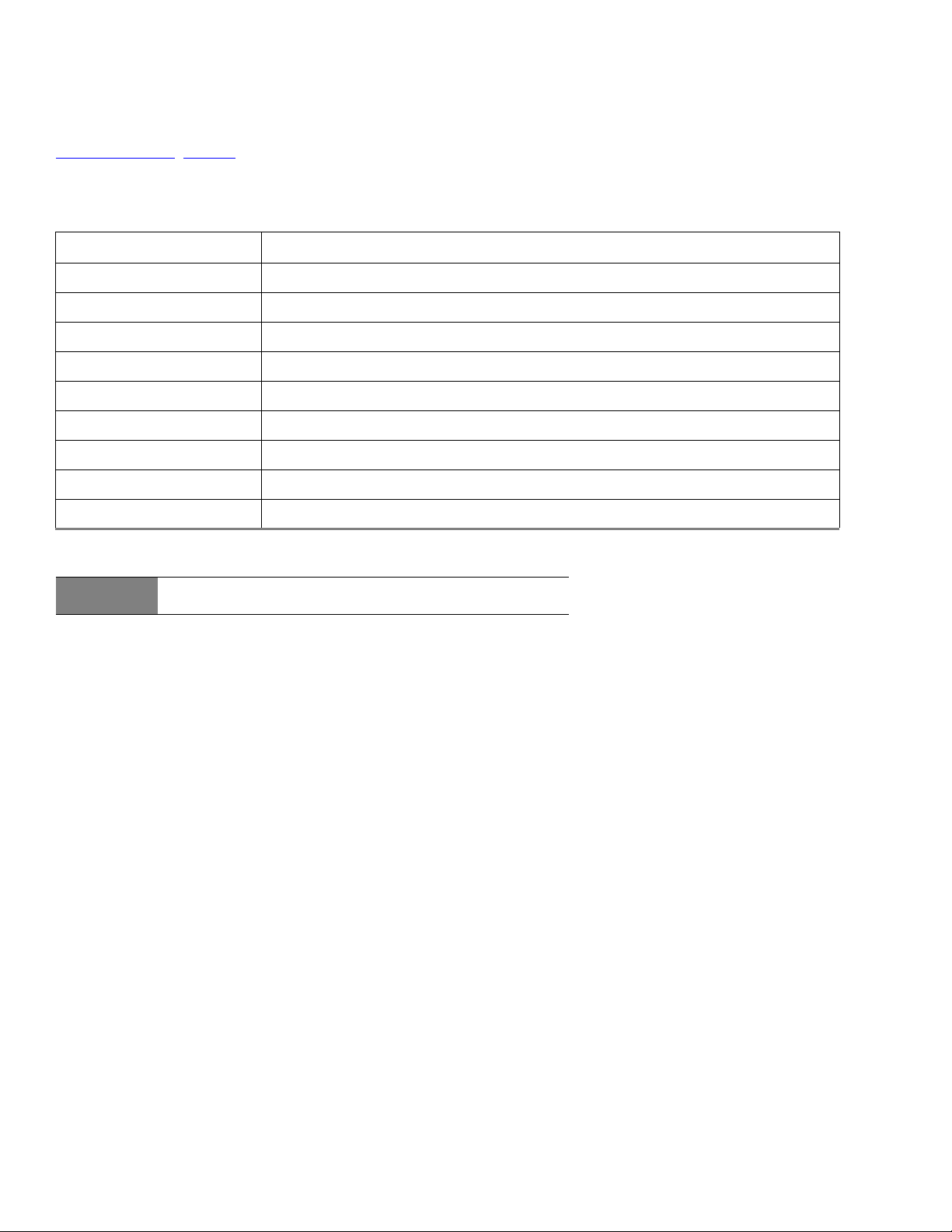
Seagate BarraCuda Product Manual, Rev. F 38
www.seagate.com SATA Interface
SeaTools diagnostic software activates a built-in drive self-test (DST S.M.A.R.T. command for D4
H
) that eliminates unnecessary drive
returns. The diagnostic software ships with all new drives and is also available at:
http://seatools.sea
gate.com.
This drive is shipped with S.M.A.R.T. features disabled. Users must have a recent BIOS or software package that supports S.M.A.R.T.
to enable this feature. The table below shows the S.M.A.R.T. command codes that the drive uses.
Table 12 S.M.A.R.T. commands
Code in features register S.M.A.R.T. command
D0
H
S.M.A.R.T. Read Data
D2
H
S.M.A.R.T. Enable/Disable Attribute Autosave
D3
H
S.M.A.R.T. Save Attribute Values
D4
H
S.M.A.R.T. Execute Off-line Immediate (runs DST)
D5
H
S.M.A.R.T. Read Log Sector
D6
H
S.M.A.R.T. Write Log Sector
D8
H
S.M.A.R.T. Enable Operations
D9
H
S.M.A.R.T. Disable Operations
DA
H
S.M.A.R.T. Return Status
Note
If an appropriate code is not written to the Features Register, the
command is aborted and 0x04 (abort) is written to the Error register.

Seagate Technology LLC
AMERICAS Seagate Technology LLC 10200 South De Anza Boulevard, Cupertino, California 95014, United States, 408-658-1000
ASIA/PACIFIC Seagate Singapore International Headquarters Pte. Ltd. 7000 Ang Mo Kio Avenue 5, Singapore 569877, 65-6485-3888
EUROPE, MIDDLE EAST AND AFRICA Seagate Technology SAS 16-18 rue du Dôme, 92100 Boulogne-Billancourt, France, 33 1-4186 10 00
Publication Number: 100804187, Rev. F
November 2017