Owner's Manuam
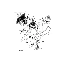
PermanentJy Lubricated
2-Stage
Twin V
AIR COMPRESSOR
o
o
o
o
o
o
o
Safety Guidelines
Assembly
Operation
Maintenance
Service and Adjustments
Repair Parts
CAUTmON, Read the Safety Guidelines
and All hstructions Carefully Before
Operating.
Sears, Roebuck and Co., Hoffman Estates, mL(}0179 U.S.A.
Visit our Craftsman website: www, sears,com/craftsman
A09710 R_v,o1/s/o._
WARRANTY ................................................ 2
SPECIFICATION CHART ..................................... 3
SAFETY GUiDELiNES ...................................... 3-8
GLOSSARY ................................................ 9
ACCESSORIES ............................................ 9
DUTY CYCLE .............................................. 9
ASSEMBLY ............................................... 10
iNSTALLATiON ......................................... 11-12
OPERATION ........................................... 13-15
MAINTENANCE ......................................... 16-17
SERVICE AND ADJUSTMENTS ............................ 18-19
STORAGE ................................................ 20
TROUBLESHOOTING GUIDE ............................. 21-23
REPAIR PARTS ......................................... 24-27
ESPANOL .............................................. 28-49
NOTES/NOTAS ............................................ 50
REPAIR PROTECTION AGREEMENTS ......................... 51
HOW TO ORDER REPAIR PARTS ...................... back cover
FULL ONE YEAR WARRANTY AIR COMPRESSOR
If this CRAFTSMAN Air Compressor fails due to a defect in materiaJ or
workmanship within one year from the date of purchase, Sears will at
its option repair or replace it free of charge. Contact your nearest Sears
Service Center (1-800-4-MY-HOME ®) to arrange for repair, or return the Air
Compressor to the place of purchase for replacement.
if this Air Compressor is used for commercial or rental purposes, this warranty
applies for oniy ninety days from the date of purchase.
This warranty gives you specific legal rights and you may have other rights
which vary from state to state.
Sears, Roebuck and Co,, Dept, 817WA, Hoffman Estates, IL 60179
A09710 2= ENG
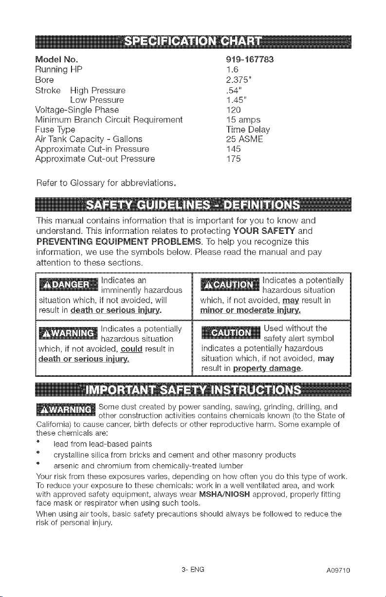
Model No, 919-167783
Running HP 1.6
Bore 2.375"
Stroke High Pressure .54"
Low Pressure 1.45"
Voltage-Single Phase 120
Minimum Branch Circuit Requirement 15 amps
Fuse Type Time Delay
Air Tank Capacity - Gallons 25 ASME
Approximate Cut-in Pressure 145
Approximate Cut-out Pressure 175
Refer to Glossary for abbreviations.
This manual contains information that is important for you to know and
understand. This information relates to protecting YOUR SAFETY and
PREVENTING EQUIPMENT PROBLEMS. To help you recognize this
information, we use the symbols below. Please read the manual and pay
attention to these sections.
Indicates an
imminently hazardous
situation which, if not avoided, will
result in death or serious in'UL_Q¢.
Indicates a potentially
hazardous situation
which, if not avoided, coumd result in
death or serious injury..
Indicates a potentially
hazardous situation
which, if not avoided, _ result in
minor or moderate injury.
Used without the
safety alert symbol
indicates a potentially hazardous
situation which, if not avoided, may
result in _ge.
n
Some dust created by power sanding, sawing, grinding, drilling, and
other construction activities contains chemicals known (to the State of
California) to cause cancer, birth defects or other reproductive harm. Some example of
these chemicals are:
_' lead from lead-based paints
_' crystalline silica from bricks and cement and other masonry products
® arsenic and chromium from chemically-treated lumber
Your risk from these exposures varies, depending on how often you do this type of work.
To reduce your exposure to these chemicals: work in a well ventilated area, and work
with approved safety equipment, always wear MSHA/NIOSH approved, properly fitting
face mask or respirator when using such tools.
When using air tools, basic safety precautions should always be followed to reduce the
risk of personal injury.
3-ENG A09710
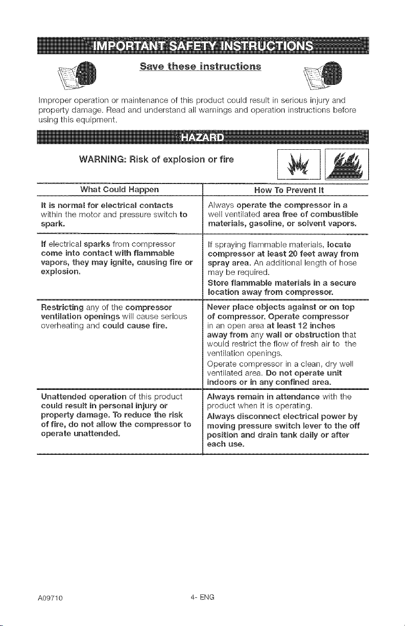
Save these instructions
improper operation or maintenance of this product could result in serious injury and
property damage. Read and understand all warnings and operation instructions before
using this equipment.
WARNING: Risk of explosion or fire _,i
What Could Happen
mtis normaB for eBectricam contacts
within the motor and pressure switch to
spark.
mfelectrical sparks from compressor
come into contact with flammable
vapors, they may ignite, causing fire or
explosion.
Restricting any of the compressor
ventilation openings will cause serious
overheating and could cause fire.
Unattended operation of this product
could result in personal injury or
property damage. To reduce the risk
of fire, do not allow the compressor to
operate unattended.
How To Prevent mt
Always operate the compressor in a
well ventilated area free of combustible
materiams, gasoline, or somvent vapors.
if spraying flammable materials, locate
compressor at meast 20 feet away from
spray area. An additional length of hose
may be required.
Store flammable materials in a secure
location away from compressor.
Never place objects against or on top
of compressor. Operate compressor
in an open area at least 12 inches
away from any wall or obstruction that
would restrict the flow of fresh air to the
ventilation openings.
Operate compressor in a clean, dry well
ventilated area. Do not operate unit
indoors or in any confined area.
ABways remain in attendance with the
product when it is operating.
ABways disconnect eBectrical power by
moving pressure switch lever to the off
position and drain tank daily or after
each use,
A09710 4= ENG
WARNING: Risk of Bursting _1
Air Tank: The following conditions could lead to a weakening of the tank, and result
in a violent tank explosion and could cause property damage or serious injury.
What Could NaoDen
Failure to properRy drain condensed
water from tank, causing rust and
thinning of the steel tank.
Modifications or attempted repairs to
the tank.
Unauthorized modifications to the
unRoader valve, safety vaBve, or any
other components which control tank
pressure,
Excessive vibration can weaken the
air tank and cause rupture or
explosion
ATTACHMENTS & ACCESSORIES:
Exceeding the pressure rating of
air toeBs, spray guns, air operated
accessories, tires, and other inflatables
can cause them to explode or fly apart,
and could result in serious injury.
Now To Prevent It
Drain tank daily or after each use.
If tank develops a leak, replace it
immediately with a new tank or replace
the entire compressoc
Never drill into, weld, or make any
modifications to the tank or its
attachments.
The tank is designed to withstand specific
operating pressures. Never make
adjustments or parts substitutions
to amter the factory set operating
pressures,
For essential control of air pressure,
you must install a pressure regulator
and pressure gauge to the air outBet
(if not equipped) of your compressor.
Follow the equipment manufacturers
recommendation and never exceed the
maximum allowable pressure rating of
attachments. Never use compressor
to inflate small low pressure objects
such as children's toys, footballs,
basketballs, etc.
WARNING: Risk from Flying Objects
What Coumd Happen Now To Prevent It
The compressed air stream can cause
soft tissue damage to exposed skin
and can propel dirt, chips, loose
particmes, and small objects at high
speed, resulting in property damage or
personal injury.
Always wear ANSI Z87.1 approved safety
gBasses with side shields when using the
compressor
Never point any nozzle or sprayer
toward any part of the body or at other
people or animals.
Always turn the compressor off and
bleed pressure from the air hose and tank
before attempting maintenance, attaching
tools or accessories.
5-ENG A09710
WARNING: Risk of Electrical Shock
What Ceumd Happen
Your air compressor is powered by
electricity. Like any other electrically
powered device, If it is not used
properly it may cause electric shock.
Repairs attempted by unqualified
personnel can result in serious injury
or death by electrocution.
Electrical Grounding: Failure to provide
adequate grounding to this product
could result in serious injury or death
from electrocution.
See grounding instructions.
Now To Prevent mt
Never operate the compressor outdoors
when it is raining or in wet conditions.
Never operate compressor with
protective covers removed or damaged.
Any emectrical wiring or repairs required
on this product should be performed by
authorized service center personneB
in accordance with national and local
electrical codes.
Make certain that the electrical circuit
to which the compressor is connected
provides proper eBectrical grounding,
correct voltage and adequate fuse
protection.
WARNING: Risk of Breathing
What Could
The compressed air directly from your
compressor is not safe for breathing.
The air stream may contain carbon
monoxide, toxic vapors, or solid
particles from the tank. Breathing these
contaminants can cause serious injury
or death.
Sprayed materials such as paint, paint
solvents, paint remover, insecticides,
weed killers, may contain harmful
vapors and poisons.
Now To Prevent It
Air obtained directly from the compressor
should never be used to supply air for
human consumption. In order to use air
_roduced by this compressor for breathing,
suitable filters and in-line safety'
equipment must be property installed.
In-line filters and safety equipment
used in conjunction with the compressor
must be capable of treating air to aH
applicable local and federal codes prior
to human consumption.
Work in an area with good cross
ventilation. Read and follow the safety
instructions provided on the label or
safety data sheets for the materials
you are spraying. Use a NIOSN/MSNA
approved respirator designed for use with
your specific application.
A09710 6- ENG
WARNING: Risk of Burns
What Could Happen
Touching exposed metal such as the
compressor head or outlet tubes, can
result in serious burns.
How To Prevent It
Never touch any exposed met.a[ parts
on compressor during or immediately
after operation. Compressor will remain
hot for several minutes after operation.
Do not reach around protective shrouds
or attempt maintenance until unit has
been allowed to cool
WARNING: Risk from Moving Parts
What Could Happen
Moving parts such as the pulley, flywheel,
and belt can cause serious injury if
they come into contact with you or your
clothing.
Attempting to operate compressor with
damaged or missing parts or attempting
to repair compressor with protective
shrouds removed can expose you to
moving parts and can result in serious
injury.
Never operate the compressor with
guards or covers which are damaged or
removed.
Any repairs required on this product
should be performed by authorized
service center personnel
WARNING: Risk of Failing
What Could Hap.pen
A portable compressor can fail from
a table, workbench, or roof causing
damage to the compressor and could
result in serious injury or death to the
operator.
How To Prevent It
Always operate compressor in a stable
secure position to prevent accidental
movement of the unit. Never operate
compressor on a roof or other eRevated
position. Use additionam air hose to
reach high mocations.
7-ENG A09710
WARNmNG: Risk of Serious mnjury or Property Damage When _B]
Transporting Compressor
(Fire, InhMatien, Damage to Vehicle Surfaces)
What Could Happen
Oil can leak or spill and could result
in fire or breathing hazard; serious
injury or death can result, oil leaks will
damage carpet, paint or other surfaces
in vehicles or trailers.
Row To Prevent it
Always place COMPRESSOR on a
protective mat when transporting to
protect against damage to vehicle from
leaks. Remove COMPRESSOR from
vehicle immediately upon arrival at your
destination.
'm_D
WARNING: Risk of Unsafe Operation
What Could Happen ........
Unsafe operation of your air compressor
could lead to serious injury or death to
you or others.
Now To Prevent mt
Review and understand all instructions
and warnings in this manual.
Become familiar with the operation and
controBs of the air compressor.
Keep operating area dear of all persons,
pets, and obstacles.
Keep chiRdren away from the air
compressor at aH times.
Do not operate the product when
fatigued or under the influence of
alcohol or drugs. Stay alert at aH times.
Never defeat the safety features of this
product.
Equip area of operation with a fire
extinguisher.
Do not operate machine with missing,
broken, or unauthorized parts.
SAVE THESE mNSTRUCTmONS
A09710 8- ENG
Become familiar with these terms
before operating the unit.
CFM: Cubic feet per minute.
SOFM: Standard cubic feet per
minute; a unit of measure of air
delivery.
PSlG: Pounds per square inch
gauge; a unit of measure of pressure.
Code Certification: Products that
bear one or more of the following
marks: UL, CUL, ETL, CETL, have
been evaluated by OSHA certified
independent safety laboratories and
meet the applicable Underwriters
Laboratories Standards for Safety.
Cut-In Pressure: While the motor
is off, air tank pressure drops as
you continue to use your accessory.
When the tank pressure drops to a
certain low level the motor will restart
automatically. The low pressure
at which the motor automatically
restarts is called "cut-in" pressure.
Cut-Out Pressure: When an air
compressor is turned on and begins
to run, air pressure in the air tank
begins to build. It builds to a certain
high pressure before the motor
automatically shuts off, protecting
your air tank from pressure higher
than its capacity. The high pressure
at which the motor shuts off is called
"cut-out" pressure.
Branch Circuit: Circuit carrying
electricity from electrical panel to
outlet.
This unit is capable of powering the following Accessories. The accessories are
available through the current Power and Hand Tool Catalog or full-line Sears
stores.
Accessories
® in Line Filter
® Tire Air Chuck
Quick Connector Sets (various
sizes)
Air Pressure Regulators
® Oil Fog Lubricators
® Air Hose: 1/4", 3/8" or 1/2" LD. in
various lengths
Refer to the selection chart located
on the unit to select the tools this unit
is capable of powering.
This air compressor pump is
capable of running continuously.
However, to prolong the life of your
air compressor, it is recommended
that a 50%-75% average duty
cycle be maintained; that is, the air
compressor pump should not run
more than 30-45 minutes in any given
hour.
9-ENG A09710
g
Contents of Carton
1 - Air Compressor
2- Wheels
2 - Shoulder Bolts, 3/8-16
2 - Nex Nuts, 3/8-16
2 - Rubber Bumpers
2 - Screws, 1/4-20 x 3/4
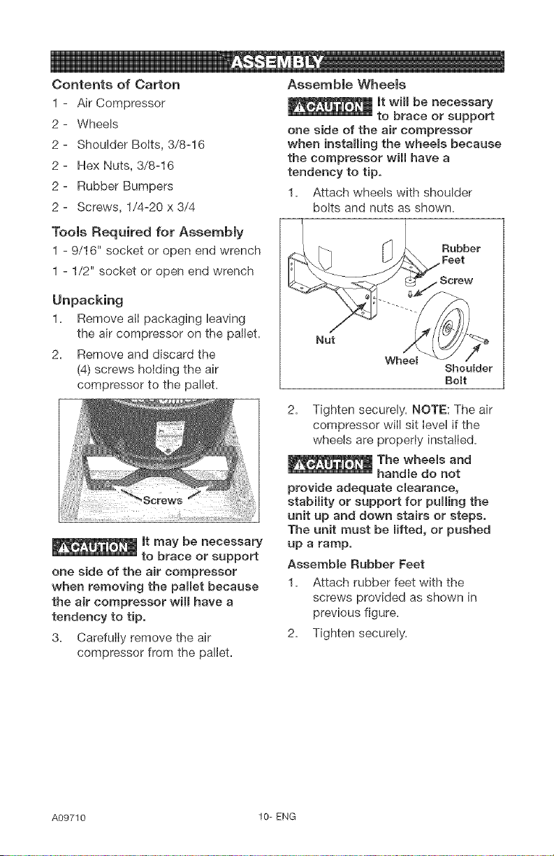
Assemble Wheels
It win be necessary
to brace or support
one side of the air compressor
when installing the wheeBs because
the compressor will have a
tendency to tip,
1. Attach wheels with shoulder
bolts and nuts as shown.
Tools Required for Assembly
1 - 9/16" socket or open end wrench
1 - 1/2" socket or open end wrench
Unpacking
1_ Remove all packaging leaving
the air compressor on the pallet.
2. Remove and discard the
(4) screws holding the air
compressor to the pallet.
_} Rubber
Feet
Wheel
, Screw
Shoulder
Bolt
one side of the air compressor
when removing the pallet because
the air compressor win have a
tendency to tip,
3. Carefully remove the air
compressor from the pallet.
2. Tighten securely. NOTE: The air
compressor wilI sit level if the
wheels are properiy installed.
The wheems and
handme do not
provide adequate c_earance,
stability or support for pulling the
unit up and down stairs or steps,
The unit must be mifted, or pushed
up a ramp,
Assembme Rubber Feet
1. Attach rubber feet with the
screws provided as shown in
previous figure.
2. Tighten securely.
A09710 10- ENG
NOW TO SET UP YOUR IMPORTANT: The outletbeingused
UNiT
Location of the Air Compressor
Locate the air compressor in a
clean, dry and well ventilated area.
The air compressor should be
located at least 12" away from the
wail or other obstructions that will
interfere with the flow of air. The
air compressor pump and shroud
are designed to allow for proper
cooling. The ventilation openings
on the compressor are necessary
to maintain proper operating
temperature. Do not place rags or
other containers on or near these
openings.The air filter must be kept
clear of obstructions which could
reduce air flow to the air compressor.
GROUNDING INSTRUCTmONS
Risk of Electrical
Shock, In the
event of a short circuit, grounding
reduces the risk of shock by
providing an escape wire for
the electric current. This air
compressor must be propermy
grounded,
The portable air compressor is
equipped with a cord having a
grounding wire with an appropriate
grounding plug (see following
illustrations). The plug must be used
with an outlet that has been installed
and grounded in accordance with all
local codes and ordinances.
1. The cord set and plug with this
unit contains a grounding pin.
This ptug MUST be used with a
grounded outlet.
must be installed and grounded in
accordance with all local codes and
ordinances.
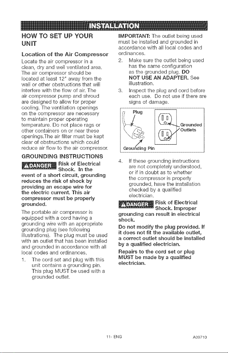
2. Make sure the outlet being used
has the same configuration
as the grounded plug. DO
NOT USE AN ADAPTER, See
illustration.
3. Inspect the plug and cord before
each use. Do not use if there are
signs of damage.
Groundiing Pin
4. If these grounding instructions
are not completely understood,
or if in doubt as to whether
the compressor is properly
grounded, have the installation
checked by a qualified
electrician.
Risk of Electrical
Shock, Improper
grounding can resumt in electricam
shock,
Do not modify the pBug provided, If
it does not fit the available outBet,
a correct outlet shouBd be installed
by a quaBified electrician,
Repairs to the cord set or pmug
MUST be made by a quamified
emectrician,
11-ENG A09710
Extension Cords
Using extension cords is not
recommended. The use of extension
cords will cause voltage to drop
resulting in power loss to the motor
and overheating.
Instead of using an extension cord,
increase the working reach of the air
hose by attaching
If an extension cord must be used,
be sure it is:
a 3-wire extension cord that has
a 3-blade grounding plug, and a
3-slot receptacle that will accept
the plug on the product
in good condition
no longer than 50 feet
12 gauge (AWG) or larger. (Wire
size increases as gauge number
decreases. 10 AWG and 8 AWG
may also be used. DO NOT USE
14 OR 16 AWG.)
Voltage and Circuit Protection
Refer to the Parts Manual for the
voltage and minimum branch circuit
requirements.
Risk of Unsafe
Operation, Certain
air compressors can be operated
on a 15 amp circuit if the following
conditions are met,
1. Voltage supply to circuit must
comply with the National
Electrical Code.
2. Circuit is not used to supply any
other electrical needs.
3. Extension cords comply with
specifications.
4. Circuit is equipped with a
15 amp circuit breaker or 15
amp time delay fuse. NOTE: If
compressor is connected to a
circuit protected by fuses, use
only time delay fuses. Time delay
fuses should be marked "D" in
Canada and "T" in the US.
If any of the above conditions
cannot be met, or if operation of
the compressor repeatedly causes
interruption of the power, it may be
necessary to operate it from a 20
amp circuit. It is not necessary to
change the cord set.
A09710 12-ENG
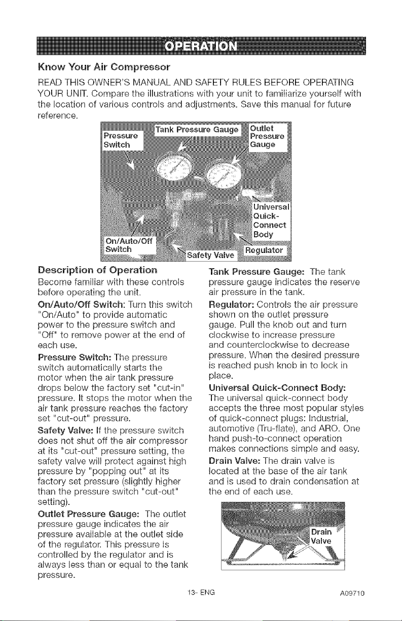
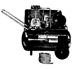
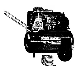
Know Your Air Compressor
READ THiS OWNER'S MANUAL AND SAFETY RULES BEFORE OPERATING
YOUR UNIT. Compare the illustrations with your unit to famiIiarize yourself with
the location of various controls and adjustments. Save this manual for future
reference.
Safety Valve
Description of Operation
Become familiar with these controls
before operating the unit.
On/Auto/Off Switch: Turn this switch
"On/Auto" to provide automatic
power to the pressure switch and
"Off" to remove power at the end of
each use.
Pressure Switch: The pressure
switch automatically starts the
motor when the air tank pressure
drops below the factory set "cut-in"
pressure, it stops the motor when the
air tank pressure reaches the factory
set "cut-out" pressure.
Safety Vamve: if the pressure switch
does not shut off the air compressor
at its "cut-out" pressure setting, the
safety valve will protect against high
pressure by "popping out" at its
factory set pressure (slightly higher
than the pressure switch "cut-out"
setting).
Outlet Pressure Gauge: The outlet
pressure gauge indicates the air
pressure avaiIable at the outlet side
of the reguIatoK This pressure is
controlled by the regulator and is
always less than or equal to the tank
pressure.
Tank Pressure Gauge: The tank
pressure gauge indicates the reserve
air pressure in the tank.
Regulator: ControIs the air pressure
shown on the outlet pressure
gauge. Pull the knob out and turn
clockwise to increase pressure
and counterclockwise to decrease
pressure. When the desired pressure
is reached push knob in to lock in
place.
Universam Quick-Connect Body:
The universal quick-connect body
accepts the three most popular styIes
of quick-connect plugs: industrial,
automotive (Tru-flate), and ARC. One
hand push-to-connect operation
makes connections simple and easy.
Brain Vamve:The drain valve is
located at the base of the air tank
and is used to drain condensation at
the end of each use.
13-ENG A09710
Cooming System (not shown}: This
compressor contains an advanced
design cooling system. At the heart of
this cooting system is an engineered
fan. It is perfectly normal for this fan
to blow air through the vent holes
in large amounts. You know that the
cooling system is working when air is
being expelled.
Air Compressor Pump (not shown}:
Compresses air into the air tank.
Working air is not available until the
compressor has raised the air tank
pressure above that required at the
air outlet.
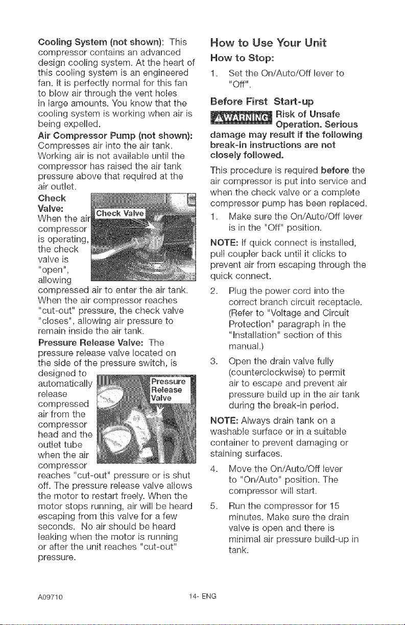
Check
Valve:
When the air
compressor
is operating,
the check
valve is
"open",
allowing
compressed air to enter the air tank.
When the air compressor reaches
"cut-out" pressure, the check valve
"closes", allowing air pressure to
remain inside the air tank.
Pressure Release Vatve: The
pressure release valve located on
the side of the pressure switch, is
designed to
automatically
release
compressed
air from the
compressor
head and the
outlet tube
when the air
compressor
reaches "cut-out" pressure or is shut
off. The pressure release valve allows
the motor to restart freely. When the
motor stops running, air wilI be heard
escaping from this valve for a few
seconds. No air should be heard
leaking when the motor is running
or after the unit reaches "cut-out"
pressure.
How to Use Your Unit
How to Stop:
1= Set the On/Auto/Off lever to
"Off"=
Before First Start-up
Risk of Unsafe
Operation, Serious
damage may resumt if the following
breakqn instructions are not
cloeemy followed,
This procedure is required before the
air compressor is put into service and
when the check valve or a complete
compressor pump has been replaced.
1= Make sure the On/Auto/Off lever
is in the "Off" position=
NOTE: If quick connect is installed,
pull coupler back until it clicks to
prevent air from escaping through the
quick connect=
2= Plug the power cord into the
correct branch circuit receptacle=
(Refer to "Voltage and Circuit
Protection" paragraph in the
"Installation" section of this
manual.)
3= Open the drain valve fully
(counterclockwise) to permit
air to escape and prevent air
pressure build up in the air tank
during the break-in period=
NOTE: Always drain tank on a
washabie surface or in a suitable
container to prevent damaging or
staining surfaces=
4= Move the On/Auto/Off lever
to "On/Auto" position= The
compressor will start.
5= Run the compressor for 15
minutes= Make sure the drain
valve is open and there is
minimal air pressure build-up in
tank=
A09710 14-ENG
6. After 15 minutes, close the drain
valve (clockwise). The air receiver
wilI fill to "cut-out" pressure and
the motor will stop.
The compressor is now ready for use.
Before Each Start=Up:
1. Place On/Auto/Off lever to "Off".
2. Pu!I regulator knob out, turn
counterclockwise until it stops.
Push knob in to lock in place.
3. Attach hose and accessories.
NOTE: The hose or accessory
wilI require a quick connect ptug
if the air outlet is equipped with a
quick connect.
pressure causes a hazardous risk of
bursting, Check the manufacturer's
maximum pressure rating for air
roomsand accessories, The reguJator
out_et pressure must never exceed
the maximum pressure rating,
Bow to Start:
1. Turn the On/Auto/Off lever
to "On/Auto" and allow tank
pressure to build. Motor will
stop when tank pressure reaches
"cut-out" pressure.
2. PulI the regulator knob out
and turn clockwise to increase
pressure. When the desired
pressure is reached push knob in
to Iock in place.
NOTE: Always operate the air
compressor in welI-ventilated areas
free of gasoline or other combustible
vapors. If the compressor is being
used to operate a sprayer DO NOT
place near the spray area.
The compressor is ready for use.
15-ENG A09710
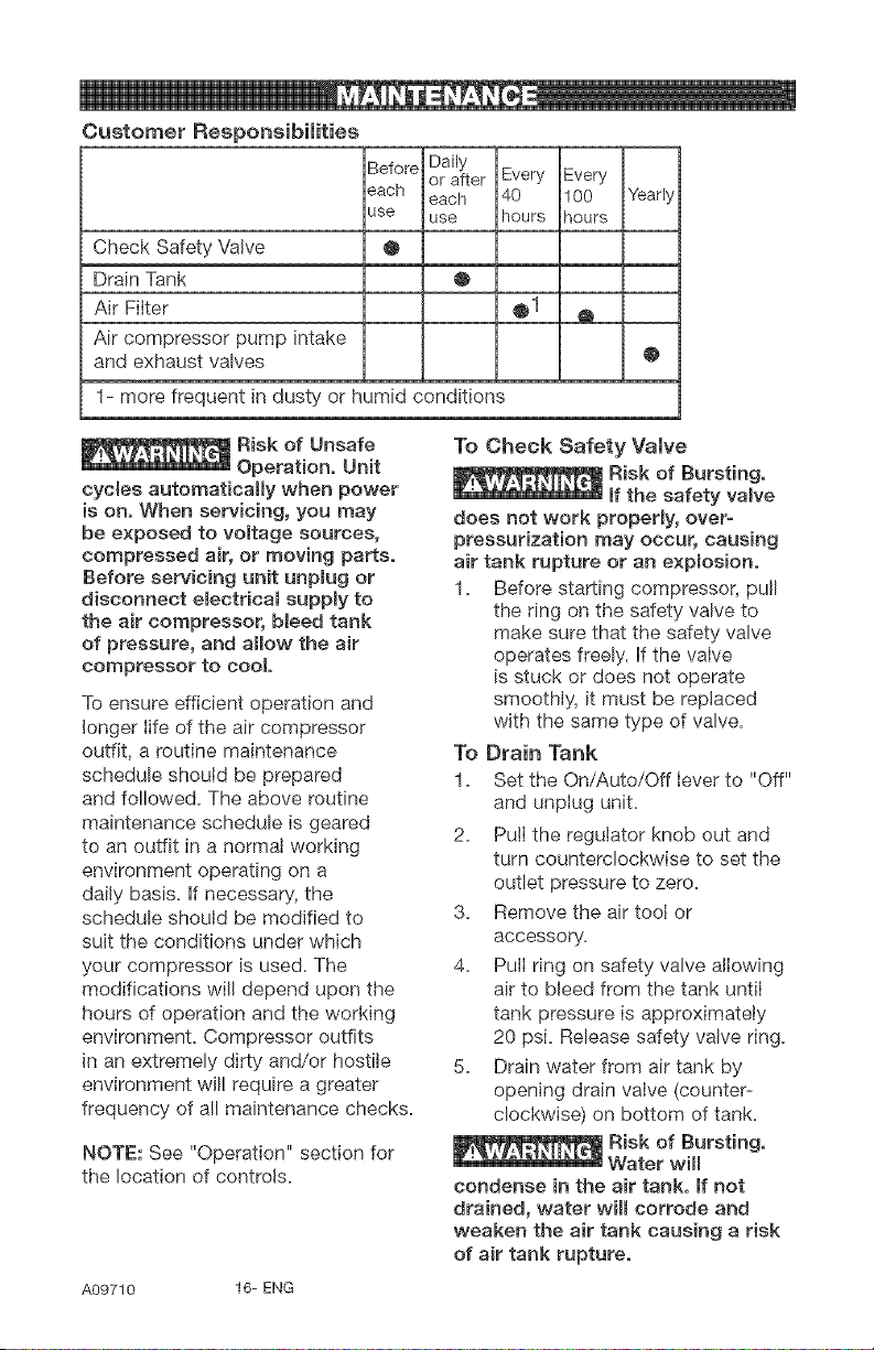
Customer Responsibilities
Before Daily
or after Every Every
each each 40 100 Yearly
use use hours qours
Check Safety Valve @
Drain Tank @
Air Filter @1 Q
Air compressor pump intake
and exhaust valves @
1- more frequent in dusty or humid conditions
cycles automatically when power
is on, When servicing, you may
be exposed to voltage sources,
compressed air, or moving parts,
Before servicing unit unpmug or
disconnect electricam supply to
the air compressor, b_eed tank
of pressure, and allow the air
compressor to cool,
To ensure efficient operation and
longer life of the air compressor
outfit, a routine maintenance
schedule should be prepared
and followed. The above routine
maintenance schedule is geared
to an outfit in a normal working
environment operating on a
dally basis. If necessary, the
schedule should be modified to
suit the conditions under which
your compressor is used. The
modifications will depend upon the
hours of operation and the working
environment. Compressor outfits
in an extremely dirty and/or hostile
environment wil! require a greater
frequency of all maintenance checks.
NOTE: See "Operation" section for
the location of controls.
To Check Safety Valve
does not work properly, over-
pressurization may occur, causing
air tank rupture or an explosion,
1. Before starting compressor, pull
the ring on the safety valve to
make sure that the safety valve
operates freely. If the valve
is stuck or does not operate
smoothly, it must be replaced
with the same type of valve.
To Drain Tank
1. Set the On/Auto/Off lever to "Off"
and unplug unit.
2. Pull the regulator knob out and
turn counterclockwise to set the
outlet pressure to zero.
3. Remove the air tool or
accessory.
4. Pull ring on safety valve allowing
air to bleed from the tank until
tank pressure is approximately
20 psi. Release safety valve ring.
5. Drain water from air tank by
opening drain valve (counter-
clockwise) on bottom of tank.
condense in the air tank, If not
drained, water will corrode and
weaken the air tank causing a risk
of air tank rupture,
A09710 16- ENG
6. After the water has been drained,
close the drain valve (clockwise).
The air compressor can now be
stored.
NOTE: If drain valve is plugged,
release all air pressure. The valve
can then be removed, cleaned, the
reinstalled.
Air Filter Inspection and
Replacement
and cylinder smeeve are very hot,
Do not touch, AHow compressor to
cool prior to servicing.
A dirty air filter will not allow the
compressor to operate at full
capacity. Keep the air filter clean at
a!l times.
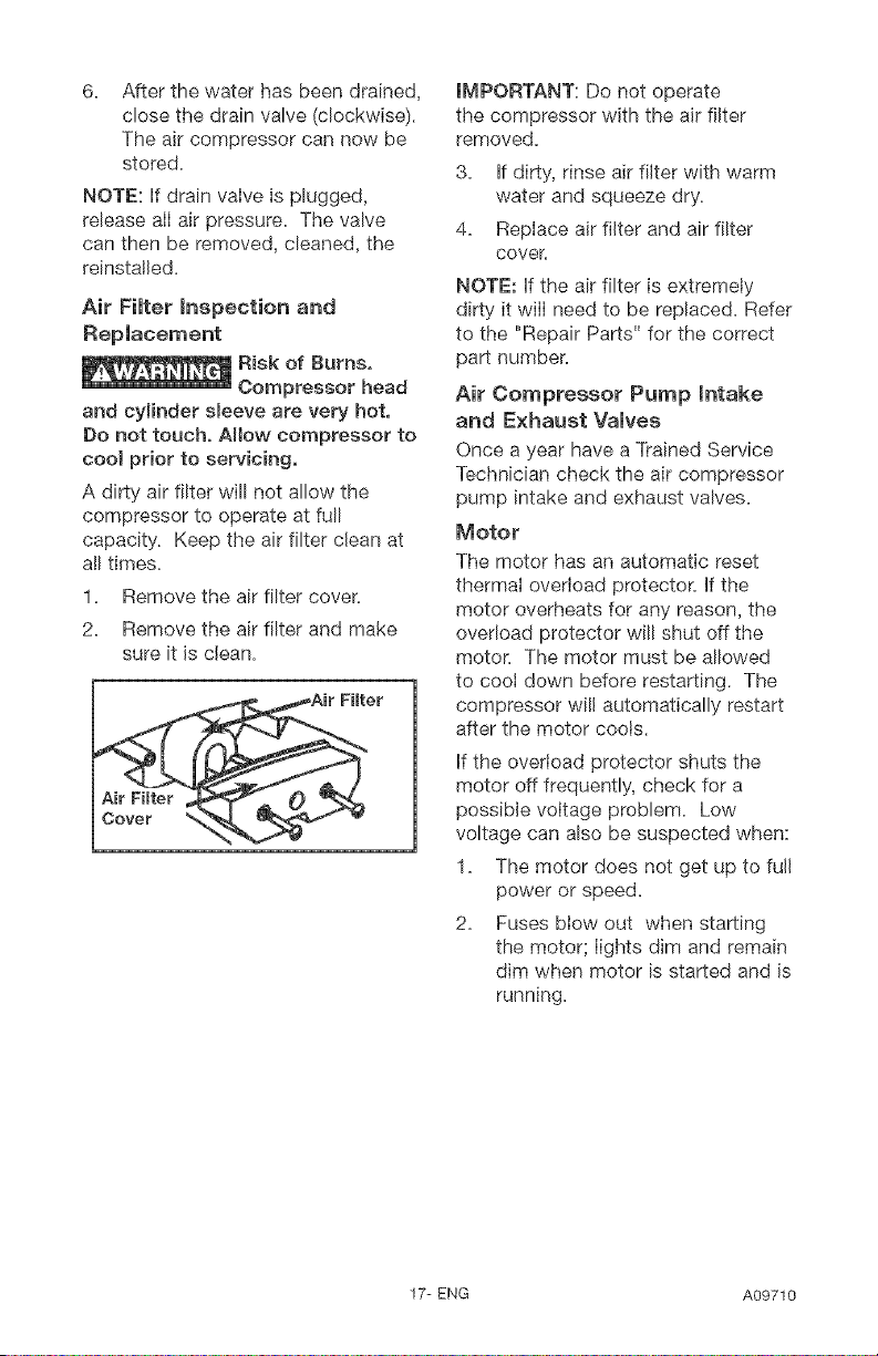
1. Remove the air filter cover.
2. Remove the air filter and make
sure it is clean.
IMPORTANT: Do not operate
the compressor with the air filter
removed.
3. If dirty, rinse air filter with warm
water and squeeze dry.
4. Replace air filter and air filter
cover
NOTE: If the air filter is extremely
dirty it will need to be replaced. Refer
to the "Repair Parts" for the correct
part number.
Air Compressor Pump Intake
and Exhaust Valves
Once a year have a Trained Service
Technician check the air compressor
pump intake and exhaust valves.
Motor
The motor has an automatic reset
thermal overload protector. If the
motor overheats for any reason, the
overload protector will shut off the
motor. The motor must be allowed
to cool down before restarting. The
compressor wi!l automatically restart
after the motor cools.
if the overload protector shuts the
motor off frequently, check for a
possible voltage problem. Low
voltage can also be suspected when:
1. The motor does not get up to fuji
power or speed.
2. Fuses blow out when starting
the motoK lights dim and remain
dim when motor is started and is
running.
17-ENG A09710
ALL MAINTENANCE AND REPAIR
OPERATIONS NOT LISTED MUST
BE PERFORMED BY A TRAINED
SERVICE TECHNICIAN.
cycles automatically when power
is on. When servicing, you may
be exposed to voltage sources,
compressed air, or moving parts.
Before servicing unit unplug or
disconnect emectdcamsupply to
the air compressor, b_eed tank
of pressure, and allow the air
compressor to cool
To RepJace or CJean Check
VaJve
1. Release all air pressure from air
tank. See "To Drain Tank" in the
"Maintenance" section.
2. Set the On/Auto/Off lever to "Off"
and unpiug unit.
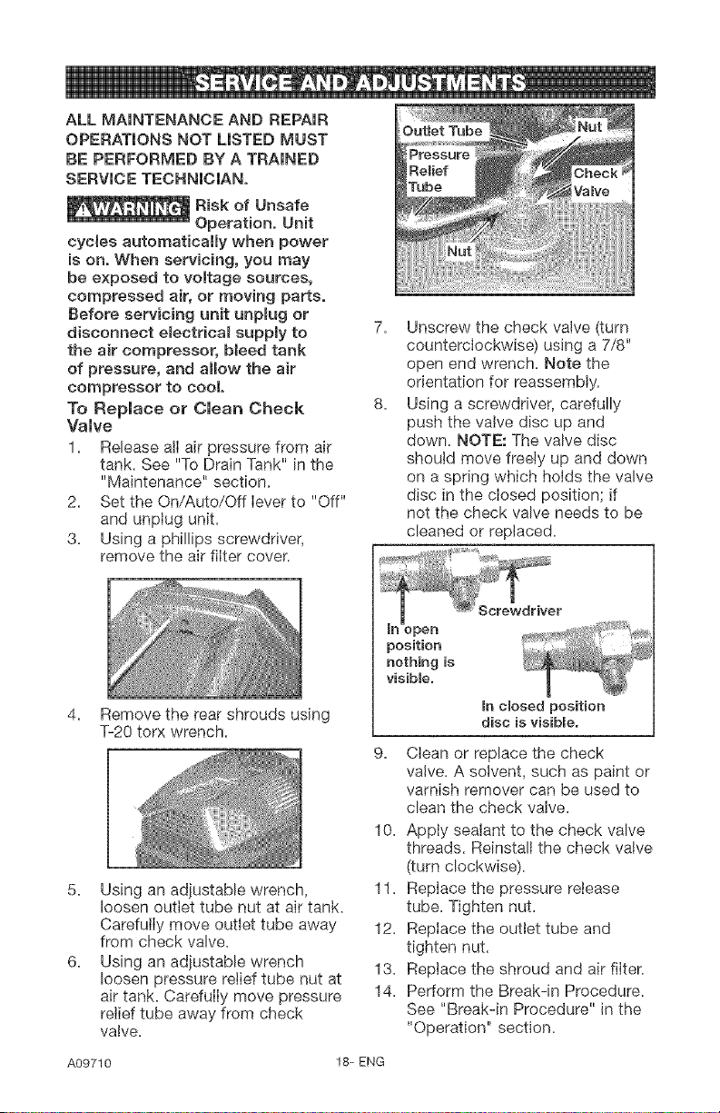
3. Using a phillips screwdriver,
remove the air filter cover.
4. Remove the rear shrouds using
T-20 torx wrench.
5. Using an adjustable wrench,
loosen outlet tube nut at air tank.
Carefuily move outlet tube away
from check valve.
6. Using an adjustable wrench
loosen pressure relief tube nut at
air tank. Carefully move pressure
relief tube away from check
valve.
7. Unscrew the check valve (turn
counterclockwise) using a 7/8"
open end wrench. Note the
orientation for reassembly.
8. Using a screwdriver, carefully
push the valve disc up and
down. NOTE: The valve disc
should move freely up and down
on a spring which hoids the valve
disc in the closed position; if
not the check valve needs to be
cleaned or replaced.
position
nothing is _ ....
visibBe.
mnclosed position
disc is visibme.
9. Clean or replace the check
valve. A solvent, such as paint or
varnish remover can be used to
clean the check valve.
10. Apply sealant to the check valve
threads. Reinstall the check valve
(turn clockwise).
11. Replace the pressure release
tube. Tighten nut.
12. Replace the outlet tube and
tighten nut.
13. Replace the shroud and air filter.
14. Perform the Break-in Procedure.
See "Break-in Procedure" in the
"Operation" section.
A09710 18- ENG
To Replace Regulator
1= Release alI air pressure from air
tank, See "To Drain Tank" in the
"Maintenance" section=
2. Set the On/Auto/Off lever to "Off"
and unplug unit.
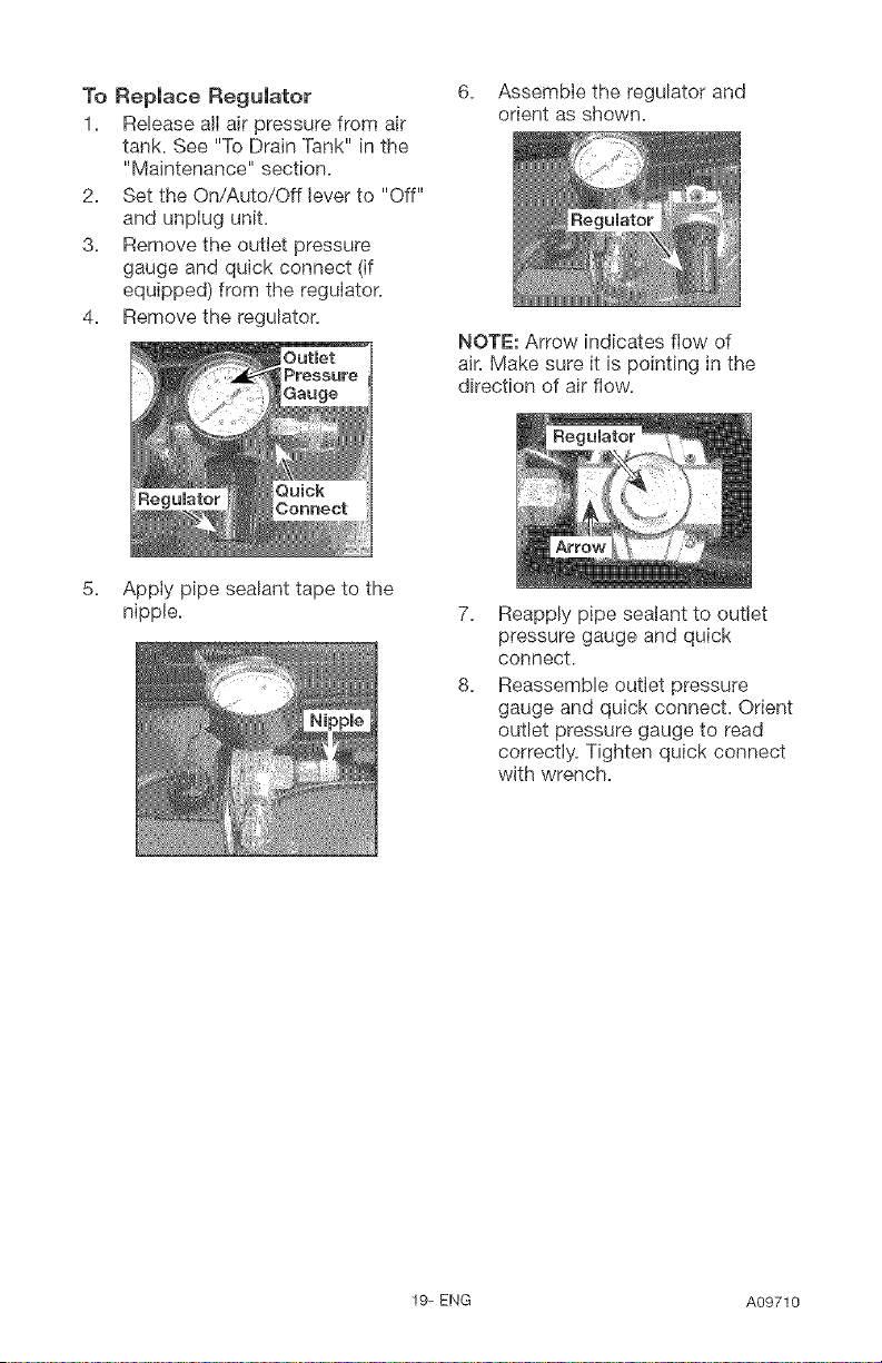
3. Remove the outlet pressure
gauge and quick connect (if
equipped) from the regulator.
4. Remove the regulator.
6. Assemble the regulator and
orient as shown.
NOTE: Arrow indicates flow of
air. Make sure it is pointing in the
direction of air flow.
Apply pipe sealant tape to the
nipple. 7=
8=
Reapply pipe sealant to outlet
pressure gauge and quick
connect.
Reassemble outlet pressure
gauge and quick connect. Orient
outlet pressure gauge to read
correctly. Tighten quick connect
with wrench.
19= ENG A09710
Before you store the air compressor,
make sure you do the following:
1. Review the "Maintenance"
section on the preceding
pages and perform scheduled
maintenance as necessary.
2. Set the On/Auto/Off Iever to "Off"
and unptug unit.
3. Turn the regulator
counterclockwise and set the
outlet pressure to zero.
4. Remove the air toot or accessory.
5. PulI ring on safety valve alIowing
air to bleed from the tank untiI
tank pressure is approximately
20 psi. Release safety valve ring.
6. Drain water from air tank by
opening drain valve on bottom of
tank.
_Risk of Bursting,
Water will
condense in the air tank, if not
drained, water will corrode and
weaken the air tank causing a risk
of air tank rupture.
7. After the water has been
drained, close the drain or drain
vaIve.
NOTE: If drain valve is plugged,
release aII air pressure. The valve
can then be removed, cleaned, and
reinstalIed.
8. Protect the electrical cord and
air hose from damage (such as
being stepped on or run over).
Wind them Ioosely around
the compressor handte, df so
equipped)
9. Store the air compressor in a
clean and dry location.
A09710 20-ENG
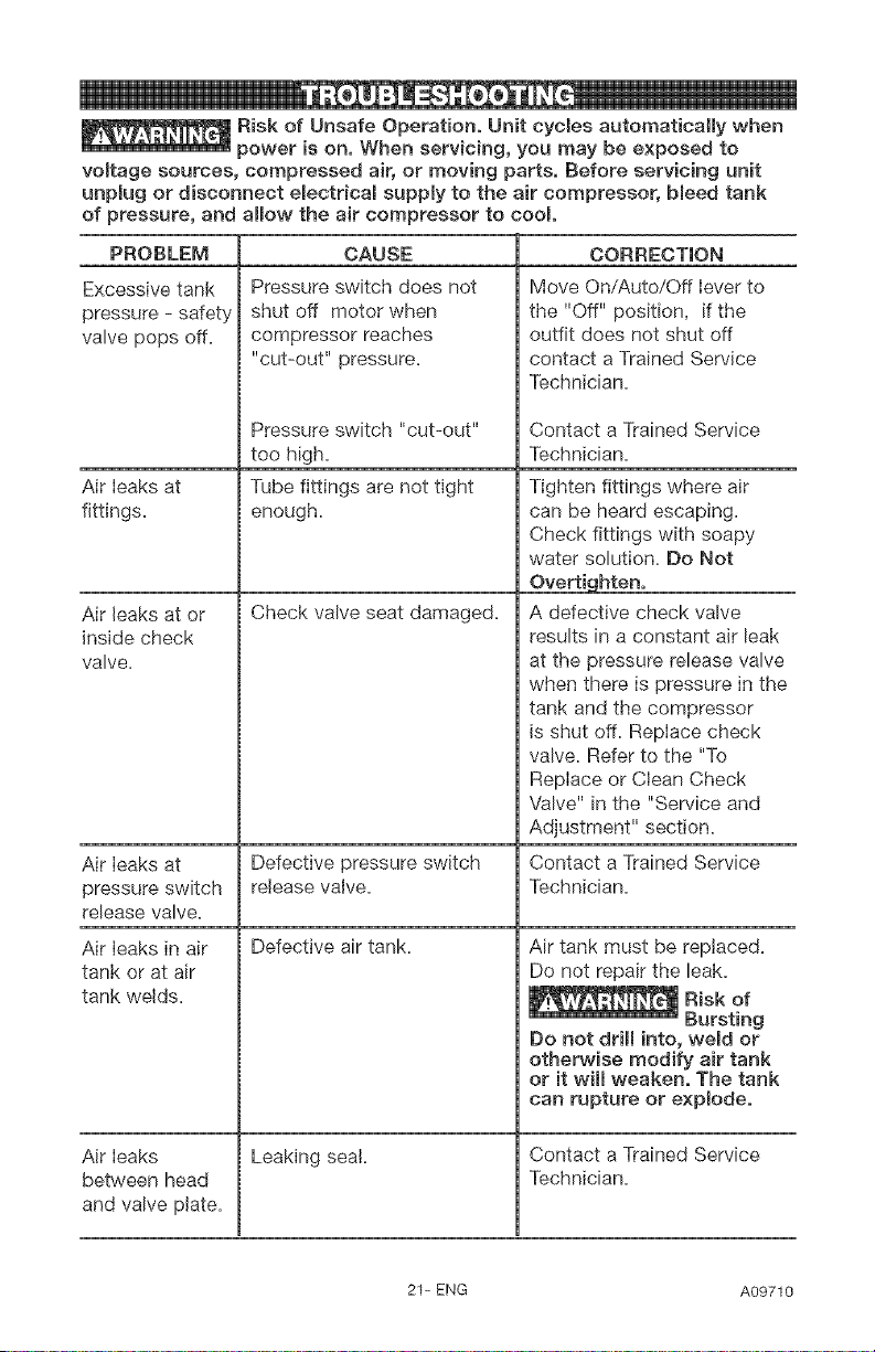
_Risk of Unsafe Operation, Unit cycles automatically when
power ison, When servicing, you may be exposed to
voffage sources, compressed air, or moving parts, Before servMng unit
unp{ug or disconnect emectdcamsupply to the air compressor, Meed tank
of pressure, and allow the air compressor to cool
PROBLEM
Excessive tank
pressure - safety
valve pops off.
Air Ieaks at
fittings.
Air leaks at or
inside check
valve.
CAUSE
Pressure switch does not
shut off motor when
compressor reaches
"cut-out" pressure.
Air leaks in air
tank or at air
tank welds.
Pressure switch "cut-out"
too high.
Tube fittings are not tight
enough.
Check valve seat damaged.
CORRECTION
Move On/Auto/Off lever to
the "Off" position, if the
outfit does not shut off
contact a Trained Service
Technician.
Air Ieaks at Defective pressure switch
pressure switch release valve.
release valve.
Defective air tank. Air tank must be replaced.
Do not repair the leak.
Leaking sea!.
Air leaks
between head
and valve plate.
Contact a Trained Service
Technician.
Tighten fittings where air
can be heard escaping.
Check fittings with soapy
water solution. Do Not
Overtighten,
A defective check valve
results in a constant air leak
at the pressure release valve
when there is pressure in the
tank and the compressor
is shut off. Reptace check
valve. Refer to the "To
RepIace or Clean Check
VaNe" in the "Service and
Adjustment" section.
Contact a Trained Service
Technician.
Do not drill into, weBd or
otherwise modify air tank
or it will weaken, The tank
can rupture or explode,
Contact a Trained Service
Technician.
21-ENG A09710
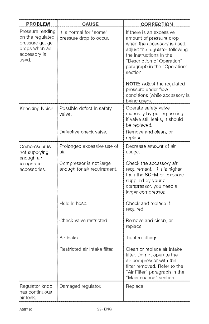
PROBLEM
Pressure reading
on the regulated
pressure gauge
drops when an
accessory is
used.
CAUSE
It is normal for "some"
pressure drop to occur.
Possible defect in safety
valve.
Knocking Noise,
Compressor is
not supplying
enough air
to operate
accessories.
Defective check valve.
Prolonged excessive use of
air.
Compressor is not large
enough for air requirement.
Hole in hose.
Check valve restricted.
Air leaks.
Restricted air intake filter.
Clean or replace air intake
filter. Do not operate the
air compressor with the
filter removed. Refer to the
"Air FiIter" paragraph in the
"Maintenance" section.
CORRECTION
if there is an excessive
amount of pressure drop
when the accessory is used,
adjust the regulator following
the instructions in the
"Description of Operation"
paragraph in the "Operation"
section.
NOTE: Adjust the regulated
pressure under flow
conditions (while accessory is
bein used.
Operate safety valve
manually by pulling on ring.
if valve still leaks, it should
be replaced.
Remove and clean, or
replace.
Decrease amount of air
usage.
Check the accessory air
requirement, if it is higher
than the SCFM or pressure
supplied by your air
compressor, you need a
larger compressor.
Check and replace if
required.
Remove and clean, or
replace.
Tighten fittings.
Regulator knob Damaged regulator. Replace.
has continuous
air leak.
A09710 22- ENG
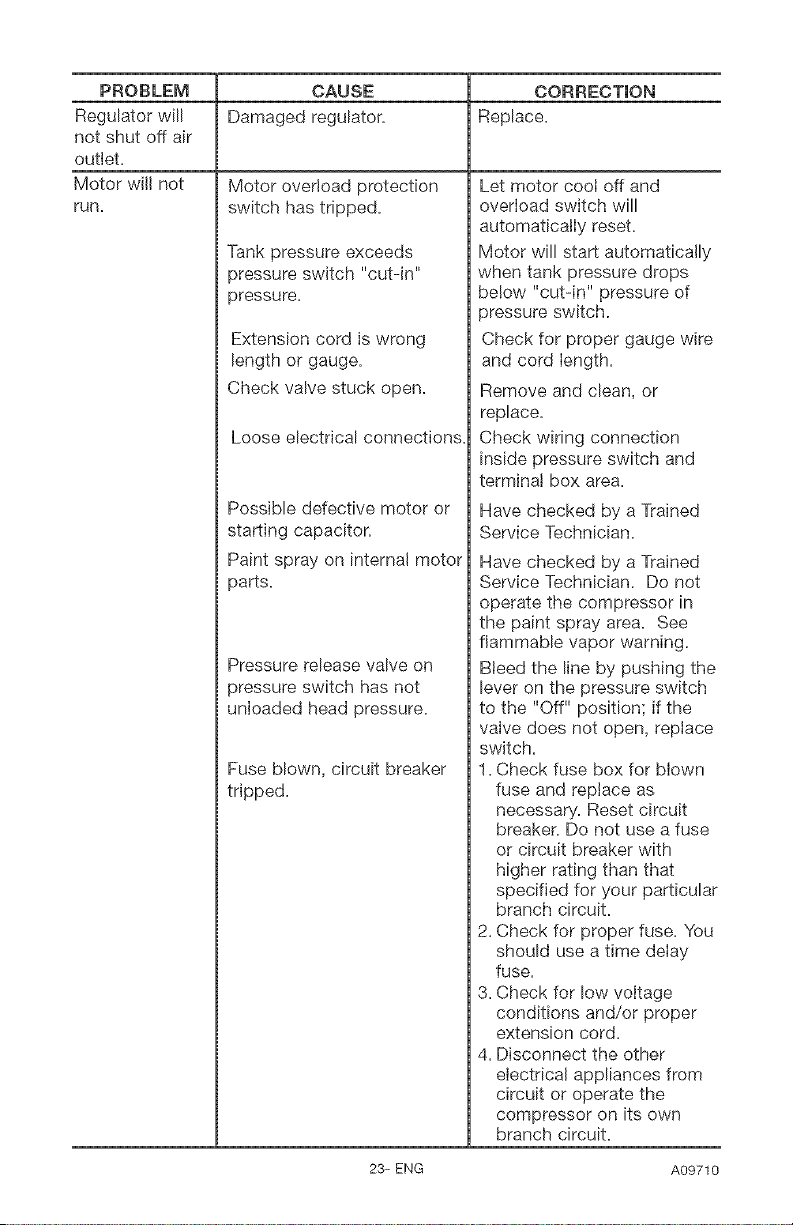
PROBLEM
Regulatorwill
notshut offair
outlet.
Motor will not
run.
OAUSE OORREOTION
Damaged regulator. Replace.
Motor overload protection
switch has tripped.
Tank pressure exceeds
pressure switch "cut-in"
pressure.
Extension cord is wrong
length oF gauge.
Check valve stuck open.
Loose ebctrical connections.
Possible defective motor or
starting capacitor.
Paint spray on interna! motor
parts.
Pressure release valve on
pressure switch has not
unloaded head pressure.
Fuse blown, circuit breaker
tripped.
Let motor coot off and
overload switch will
automaticatly reset.
Motor will start automatica!ly
when tank pressure drops
be!ow "cut-in" pressure of
pressure switch.
Check for proper gauge wire
and cord length.
Remove and clean, or
replace.
Check wiring connection
inside pressure switch and
terminat box area.
Have checked by a Trained
Service Technician.
Have checked by a Trained
Service Technician. Do not
operate the compressor in
the paint spray area. See
flammable vapor warning.
Bleed the line by pushing the
lever on the pressure switch
to the "Off" position; if the
valve does not open, replace
switch.
1. Check fuse box for blown
fuse and replace as
necessary. Reset circuit
breaker. Do not use a fuse
or circuit breaker with
higher rating than that
specified for your particular
branch circuit.
2. Check for proper fuse. You
should use a time delay
fuse.
3. Check for low voltage
conditions and/or proper
extension cord.
4. Disconnect the other
electrical appliances from
circuit oFoperate the
compressor on its own
branch circuit.
23-ENG A09710
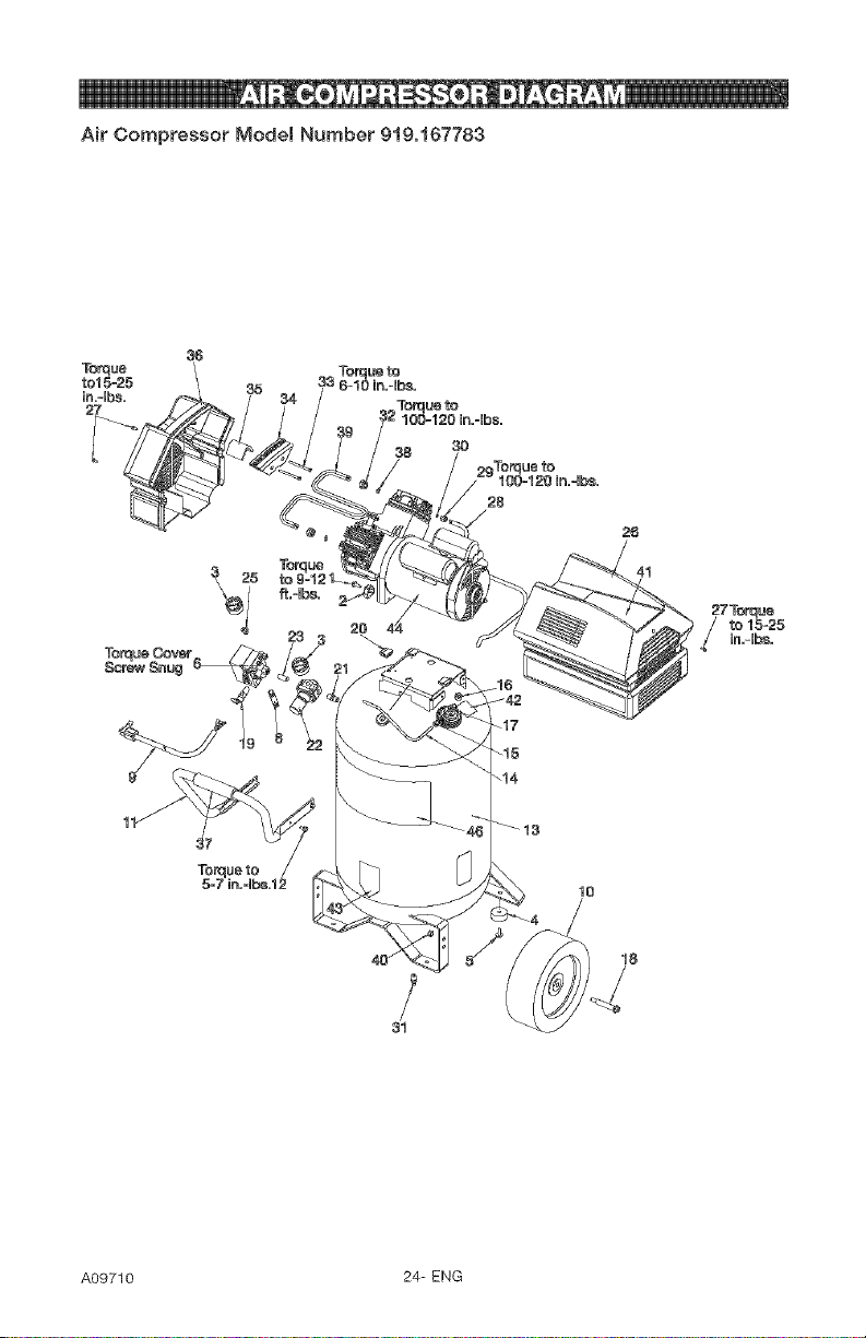
Air Compressor Model Number 919,167783
35
25
3O
Torqueto
lo
31
18
A09710 24- ENG
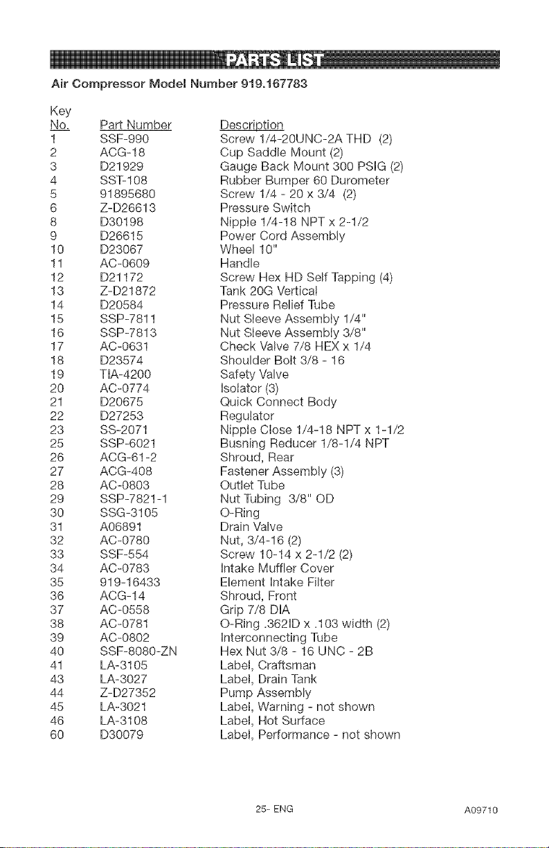
Air Compressor Model Number 919o167783
Key
No_ Part Number Description
1 SSF-990 Screw 1/4-20UNC-2A THD (2)
2 ACG-18 Cup Saddle Mount (2)
3 D21929 Gauge Back Mount 300 PSIG (2)
4 SST-108 Rubber Bumper 60 Durometer
5 91895680 Screw 1/4 - 20 x 3/4 (2)
6 Z-D26613 Pressure Switch
8 D30!98 Nipple 1/4-18 NPT x 2-1/2
9 D26615 Power Cord Assembly
10 D23067 Wheel 10"
11 AC-0609 Handle
12 D21172 Screw Hex HD Self Tapping (4)
13 Z-D21872 Tank 20G Vertica!
14 D20584 Pressure Relief Tube
15 SSP-7811 Nut Sieeve Assembly 1/4"
16 SSP-7813 Nut Sleeve Assembly 3/8"
17 AC-0631 Check Valve 7/8 HEX x 1/4
18 D23574 Shoulder Bolt 3/8 - 16
19 TIA-4200 Safety Valve
20 AC-0774 Isolator (3)
21 D20675 Quick Connect Body
22 D27253 Regulator
23 SS-2071 Nipple Close 1/4-18 NPT x 1-1/2
25 SSP-6021 Bushing Reducer 1/8-1/4 NPT
26 ACG-61-2 Shroud, Rear
27 ACG-408 Fastener Assembly (3)
28 AC-0803 Outlet Tube
29 SSP-7821-1 Nut Tubing 3/8" OD
30 SSG-3105 O-Ring
31 A06891 Drain Valve
32 AC-0780 Nut, 3/4-16 (2)
33 SSF-554 Screw 10-14 x 2-1/2 (2)
34 AC-0783 intake Muffler Cover
35 919-16433 Element intake Filter
36 ACG-14 Shroud, Front
37 AC-0558 Grip 7/8 DIA
38 AC-0781 O-Ring .3621D x .103 width (2)
39 AC-0802 interconnecting Tube
40 SSF-8080-ZN Hex Nut 3/8 - 16 UNC - 2B
41 LA-3105 Label, Craftsman
43 LA-3027 Label, Drain Tank
44 Z-D27352 Pump Assembly
45 LA-3021 Label, Warning - not shown
46 LA-3108 Label, Not Surface
60 D30079 Label, Performance - not shown
25-ENG A09710
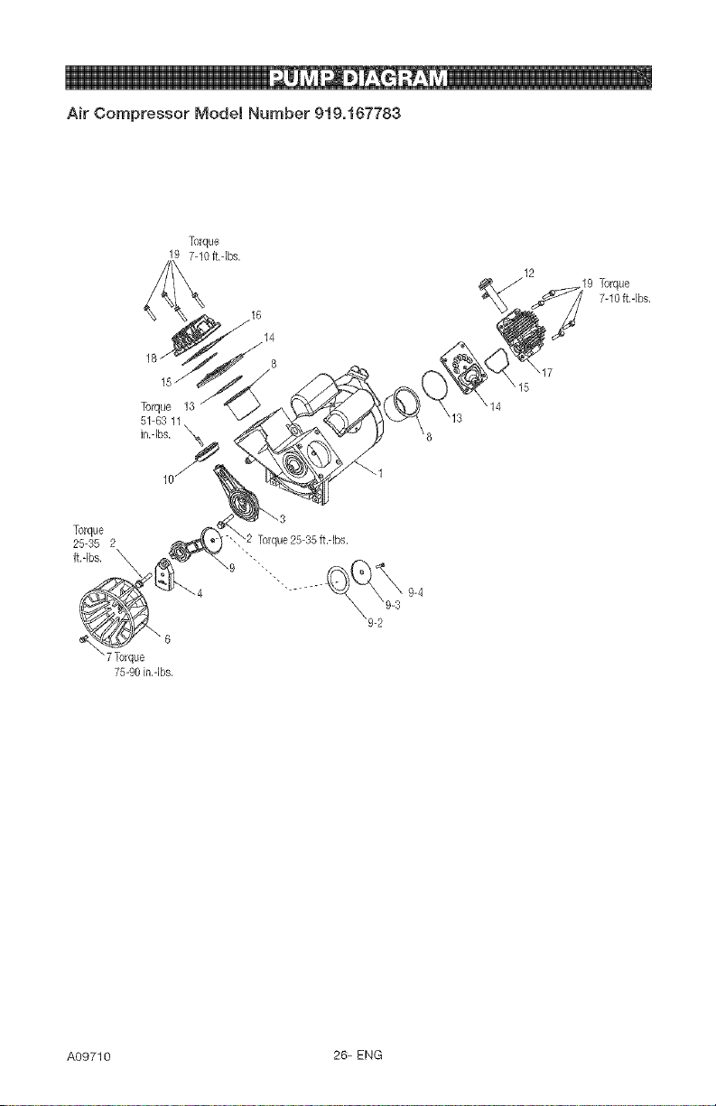
Air Compressor Model Number 919o167783
Torque
19 7-10 ff.qbs.
16
14
8
Torque 13 \14
51-63 11 13
in.-Ibs. \8
\15
12
\17
7-10 ff,-Ibs,
Torque
25-35 2
ft.qbs. _
7Torque
75-90in.qbs.
A09710 26-ENG
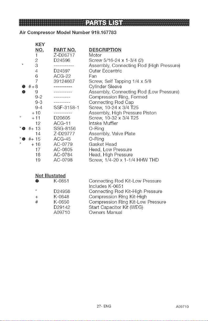
Air Compressor Model Number 919,167783
KEY
NO, PART NO,
1 Z-D26717
2 D24596
3
4 D24597
6 ACG-22
7 39124607
@ #+8
@ 9
9-2
9-3 .........
9-4 SSF-3158-1
+10 ..........
+ 11 D20605
12 ACG-11
*@ #+ 13 SSG-8156
14 Z-D29777
*@ #+ 15 ACG-45
+ 16 AC-0779
17 AC-0805
18 AC-0784
19 AC-0798
DESCRIPTION
Motor
Screw 5/16-24 x 1-3/4 (2)
Assembly, Connecting Rod (High Pressure)
Outer Eccentric
Fan
Screw, Self Tapping 1/4 x 5/8
Cylinder Sleeve
Assembly, Connecting Rod (Low Pressure)
Compression Ring, Formed
Connecting Rod Cap
Screw, 10-24 x 3/4 T25
Assembly, High Pressure Piston
Screw, 10-32 x 3/4 T25
Intake Muffler
O-Ring
Assembly, VaNe Plate
O-Ring
Gasket Head
Head, Low Pressure
Head, High Pressure
Screw, 1/4-20 x 1-1/4 HHW THD
Not lllustated
@ K-0651
D24958
+ K-0648
# K-0650
D29142
A09710
Connecting Rod Kit-Low Pressure
Includes K-0651
Connecting Rod Kit-High Pressure
Compression Ring Kit-High
Compression Ring Kit-Low Pressure
Start Capacitor Kit (WEG)
Owners Manual
27- ENG A09710
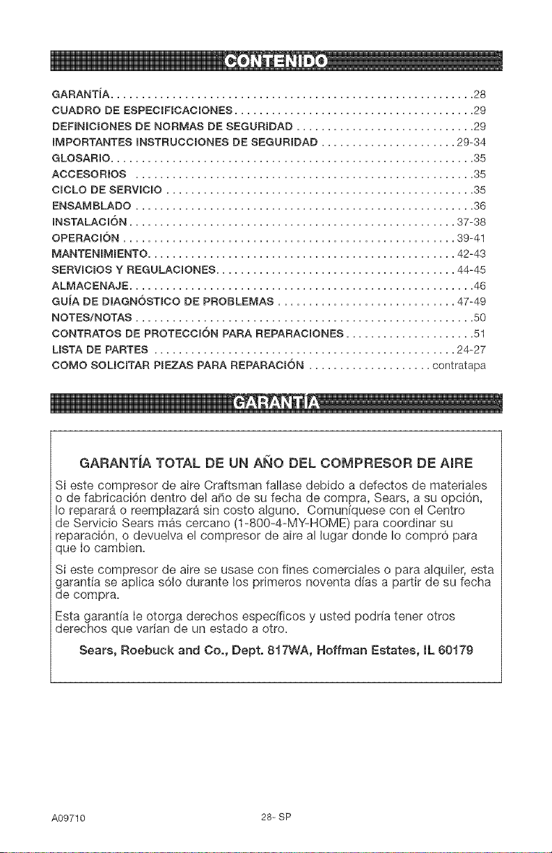
GARANTiA TOTAL DE UN ANO DEL COMPRESOR DE AIRE
Si este compresor de aire Craftsman fallase debido a defectos de materia!es
o de fabricaci6n dentro del a_o de su fecha de compra, Sears, a su opci6n,
Io reparar#_ o reemptazara sin costo alguno. Comunfquese con el Centro
de Servicio Sears mas cercano (1-800-4-MY-HOME) para coordinar su
reparaci6n, o devuelva el compresor de aire al lugar donde Io compr6 para
que Io cambien.
Si este compresor de aire se usase con fines comerciaies o para alquiler, esta
garantia se aplica s61o durante los primeros noventa dias a partir de su fecha
de compra=
Esta garantia ie otorga derechos especfficos y usted podria tener otros
derechos que varian de un estado a otro.
Sears, Roebuck and Co., Dept. 817WA, Hoffman Estates, IL 60179
A09710 28= SP
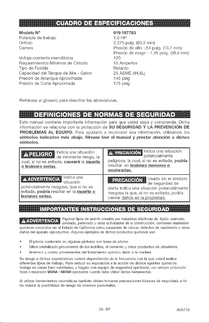
ModeRo N"
Potencia de trabajo
©rificio
CarFel'a
Voltaje-corriente manofAsica
Requerimientos Minimos de Circuito
Tipo de Fusible
Capacidad del Tanque de Aire - Galon
Presi6n de Arranque Aproximada
Presi6n de Corte Aproximada
919.167783
1,6 HP
2,375 pulg. (60,3 ram)
Presi6n de alto -,54 pulg. (13,7 mm)
Presi6n de mugir - 1,45 pulg. (36,8 mm)
120
15 Amperios
Retardo
25 ASME (94,6L)
145 psig
175 psig
Refi6rase al glosario para descifrar las abreviaturas.
Este manual contiene importante informaci6n para que usted sepa y comprenda. Dicha
informaci6n se relaciona con la protecci6n de SLI SEGLIRIDAD Y LA PREVENCK)N DE
PROBLEMAS AL EQLIIPO. Para ayudarlo a reconocer esa informaci6n, utilizamos los
s_mbolos indicados m_s abajo. S_rvase leer el manual y prestar ateneian a dichos
s_mbolos.
_ Indica una situaci6n
de inminente riesgo, la
cual, si no es evitada, causar_ la muerte
o lesiones serias.
Indica una
situaci6n
3otencialmente riesgosa, que si no es
evitada, podr_a resultar en la muerte o
lesiones serias.
Indica una situaci6n
potencialmente
peligrosa, la cual, si no es evitada, podr_a
resultar en lesiones menores o
moderadas.
Usado sin el sfmbolo
de seguridad de
alerta indica una situaci6n potencialmente
riesgosa la que, si no es evitada, podrfa
causar dar'ios en la_iedad.
, ,_ o. , , AIgunos tipos de aserrin creados per maquinas electricas de lijado, aserrado,
amolado, perforado u otras actividades de la construcci6n, contienen materiales
quimicos conocidos (en el Estado de California) como causantes de cancer, defectos de nacimiento u otros
da_os del aparato reproductivo. AIgunos ejemplos de dichos productos quimicos son:
El plomo contenido en a_gunas pinturas con base de plomo
Silice cristalizado proveniente de los ladril_os, el cemento y otros productos de alba_Heria
Arsenico y cromo provenientes del tratamiento quimico dado a la madera
Su riesgo a dichas exposiciones vadara dependiendo de la frecuencia con la que usted realice
difer_ntes tipos de trabajo. Pars reducir su exposici6n a _aacci6n de dichos agentes quimicos:
trabaie en zonas bien ventiladas, y hagalo con equipo de seguridad aprobado, use siempre pretecci6n
facial o respirador MSHA / NUOSHaprobados cuando deba utilizar dichas herramientas.
AI utilizar herramientas neumAticas tambien deben tomarse precauciones basicas de seguddad, a fin
de reducir la posibi_idad de riesgo de lesiones personales.
29- SP A09710
, GUARDE ESTAS |NSTRUCCiONES
La operaci6n o el mantenimiento inadecuados de este producto podrian
ocasionar sedas lesiones y dafios a la propiedad, Lea y comprenda todas las
advertencias e instrucciones de funcionamiento antes de utilizer este equipo,
i
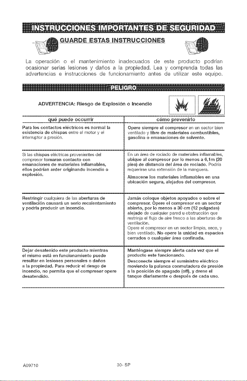
ADVERTENCIA: Riesgo de Explosi6n o mncendio
qu_ puede occurrir
Para los contaetos el6ctricos es normal la
e×istencia de chispas entre el motor y el
interruptor a presion.
Si las chispas electdcas provenientes de_
compresor tomaran contacto con
emaeaciones de materiaUes hfiamables,
eHes podrian arder originando incendio o
e×plosi6n.
Restringir cualquiera de las aberturas de
ventiiaci6n causara un eerie recaUentamiente
y podria producir un incendio.
Dejar desatenido este producto mientras
el mismo esta en funcionamiente puede
resuUtar en lesiones persenaUes o daSos
a Uapropiedad. Pare reducir e8 riesgo de
incendio, no permita que e{ eompresor opere
desatendide.
c6mo preveniHo
Opere siempre eUcempresor en un sector bien
ventilado y Hbre de materiaUes combustiMes,
gasoUina o emanaeienes de soUvente.
En un ar_a de rociado de materia_es inflamables,
ubique al compresor per Io menos a 6,1m (20
pies) de distaneia deU area de reciade. Podria
requerirse una extensi6n de la manguera.
AUmacene Uos materiaUes infiamables en una
ubicaci6n segura, alejados del compresor.
Jam_s coUoque objetos apoyados o sobre eU
oompreser. Opere eB compresor en un sector
abierto, per mo menos a 30 cm (12 pulgadas)
alejado de cua_quier pared u obstruccion que
restrinja el fiujo de air_ fresco alas aberturas de
ventilaci6n=
Opere el compresor en un sector limpio, seco, y
bien venti_ado= No opere la unidad en espaeios
cerrados o cuaUquier _rea eonfinada.
Mant_ngase siempre a{erta cada vez que el
producto este funcionando=
Desconecte siempre eUsuministro eUectrico
moviende UapaUanca conmutadora de presi6n
a Uapesici6n de apagado (off), y drene eU
tanque diariamente o despu_s de carla uso_
A09710 30- SP
i _ e] !
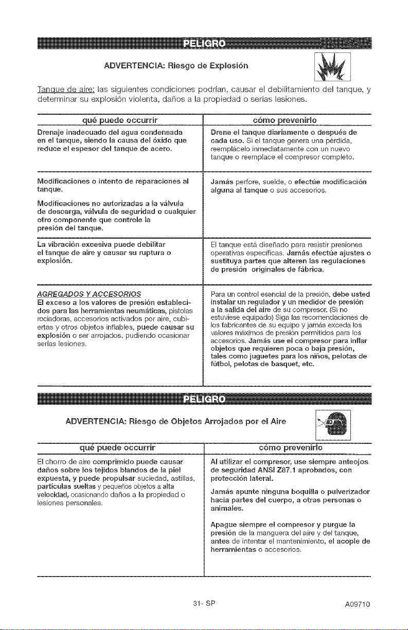
ADVERTENCIA: Riesgo de E×plosi6n
Tanque de aire: las siguientes condiciones podrfan, causar el debilitamiento del tanque, y
determinar su explosi6n violenta, danos a la propiedad o serias lesiones=
qu_ puede occurrir c6mo prevenirRo
Drenaje inadecuado del agua condeneada Drene el tanque diariarnente o despu_s de
en eUtaaque, eiendo Uacausa de1 6xido que carla ueo= Si el tanque genera una p6rdida,
reduce eUespesor deU tanque de acero, r_empl&celo inmediatamente con un nuevo
tanque e r_emp[ace e_cempr_ser complete.
Modificaciones o intento de reparaciones a] Jamas perfore, sue_de, o efectQe modificaci6n
tanque, aUguea aUtanque o sus accseorios.
Modificacienes no autorizadas a Uavalvula
de descarga, v_lvuUa de seguridad o cuaiquier
otto componente que controle la
preei6n deU tanque.
La vibraciSn e×cesiva puede debHitar El tanque set& diseSado para r_sistir presiones
el tanque de aire y causar su ruptura o operativas espec[ficas, Jam_s efectQe ajuetes o
explosi6rL sustituya partes que aUteren las regulacionee
de presi6n originalee de f_brica.
AGREGADOS Y ACCESOR/OS
EUe×ceso a los vaUores de preei6n estabUeci-
dos para Uasherramientas neum_ticas, pistolas
reciadoras, accesedos activadse per aire, cubi-
ertas y etr_s ebjetes inflables, puede causar su
e×plosi6n e set arrojados, pudiende ecasionar
serias [esiones,
Rata un control esencial de la presion, debe usted
inetalar an reguUador y un medidor de preei6n
a la salida del aire de su compresor: (Si no
estuviese equipado) Siga las recomendacioses de
_os fabdcantes de su equipo y jamas exceda los
valeres maximse de presi6n permitidse para los
acceserise. Jarn_s use et cornpresor para inflar
objetoe que requieren poca o baja presi6n,
tales come juguetee para Uos niSoe, peUotas de
f'3tboL peletae de baequet, etc.
e]
ADVERTENCIA: Riesgo de Objetos Arrojados pot el Aire
qu_ puede occurrir c6mo preveniHo
El chorro de aire comprirnido puede causar
dafios sobre Uostejidos blandos de la pieU
e×puesta, y puede prepuUsar suciedad, astil_as,
part_cuUas sueUtas y pequedos ebjetos a aUta
veUeeidad, ocasionando da[tes a la prepiedad e
lesieses persenales.
AI utilizar el compresor, use siempre anteojos
de seguridad ANSI Z87.1 aprobados, con
protecci6n UateraL
Jarnas apunte ninguna boquiHa o pulverizador
hacia partes de_ cuerpe, a otrae personas e
a_'_imales.
Apague siempre el compresor y purgue _a
presiSn de la manguera del aire y del tanque,
antes de intentar el mantenimiento, el acop_e de
herramientae o accesorios.
31= SP A09710
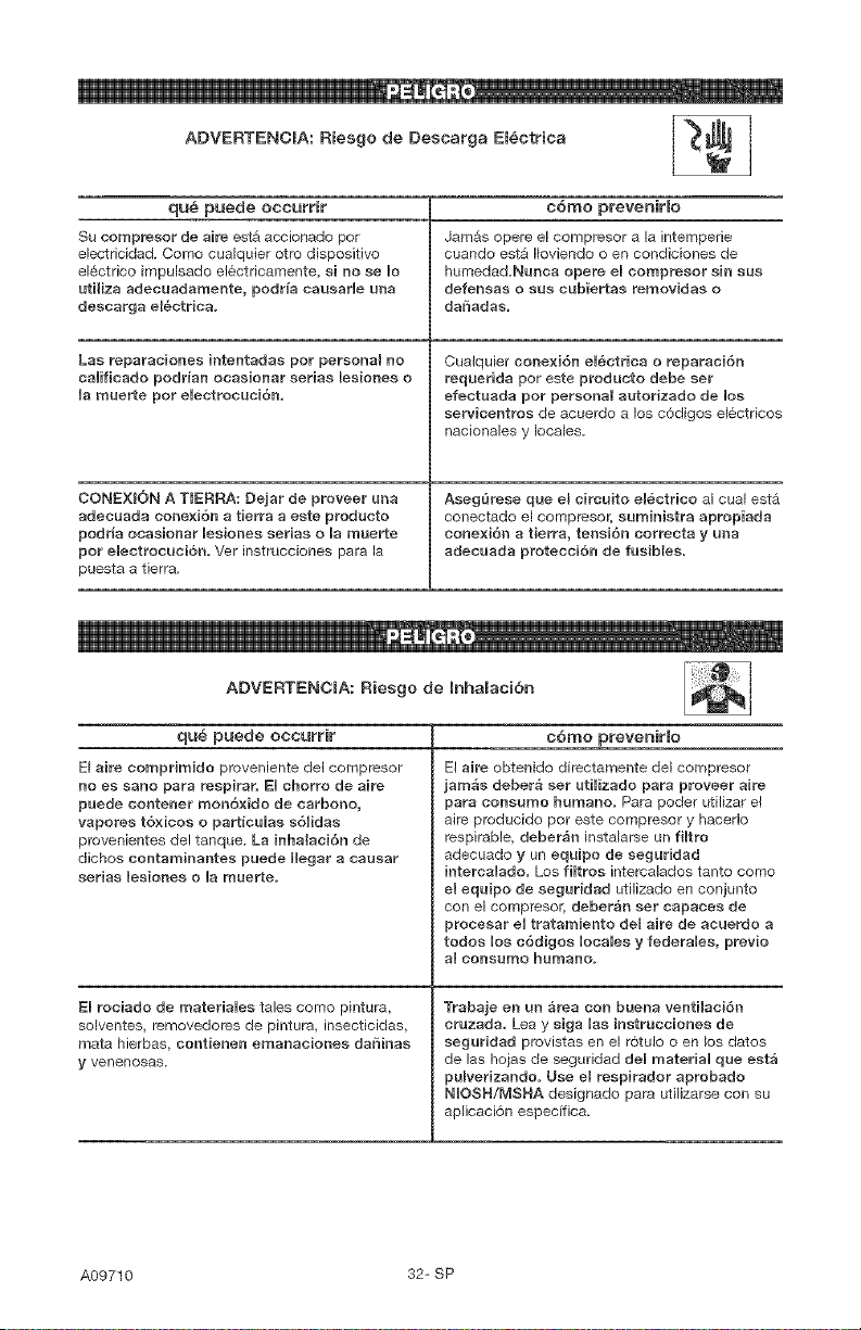
ADVERTENCIA: Riesgo de Descarga El_ctrica _-_i
qu_ puede occurrir c6mo prevenir[o
Su compresor de aire est& accionado per Jam&s opere el compresor a [a intemperie
electficidad. Come cua[quier otto dispositivo cuando est_ Iloviendo o en condiciones de
e_6ctrico irnpu[sado electdcamente, si no se le humedad.Nunca epere el compresor sin sus
uti_iza adecuadamente, podr_a causarle una defensas o sus cubiertas removidas o
desearga em_ctr{ea, daSadas.
Las reparaciones intentadas per personal no
califieado podr_an ocasionar serias lesiones o
Ua muerte per eUectroeuci6n,
CONEXI6N A TIERRA: Dejar de proveer una
adecuada eene×i6n a tierra a este producto
podria eeasienar Uesiones serias o Uamuerte
per eBectrocuciSn. Ver instrucciones para la
puesta a tierra.
Cualquier eonexi6n el_ctrica o reparaci6n
reqaerida per este producto debe ser
efectuada per personal autorizado de Ues
servicentres de acuerde a los c6digos el_ctrices
naciona_es y locales,
AsegQrese que e8 circuito el_ctrico al cual esta
conectado el compresor, suministra aprepiada
cone×i6n a tierra, tensi6n correcta y una
adecuada protecci6n de fusibles.
ADVERTENCIA: Riesgo de mnhalaci6n
qu6 puede occurrir c6mo prevenirmo
El aire comprimido proveniente del compresor
no es sane para respirar. EUehorro de aire
puede contener mon6×ide de carbono,
vapores t6×icos o part_culas s6Uidas
provenientes de! tanque. La inhalaci6n de
cliches contaminantes paede Hegar a caasar
serias Uesiones o Uamuerte.
EU rociado de materiaUes tales come pintura,
solventes, removedores de pintura, insecticidas,
mata hierbas, eentienen emanaciones daSinas
y venenosas,
El aire obtenido directamente del compresor
jam_s debera set utHizado para proveer aire
para consume humane. Para poder uti]izar el
air_ producido per este compresor y hacerle
respirable, deberan insta_arse un fiUtre
adecuado y un equipe de seguridad
iutercalado. Los fiUtros intercalados tanto come
e{ equipe de seguridad utilizado en conjunto
con el compresor_ deberan set capaces de
procesar eUtratamiento de{ aire de acuerdo a
redes Uos c6digos UecaUes y federaUes, previe
a_ consume hunlano_
Trabaje en un area con buena ventiiaci6n
cruzada. Lea y siga Uas instrucciones de
seguridad provistas en el r6tulo o en _osdates
de las hojas de seguridad deU materiaU que est_
pulverizande. Use e_ respirador aprebado
N_OSH/MSHA designado para utilizarse con su
ap[icaci6n especifica.
A09710 32-SP
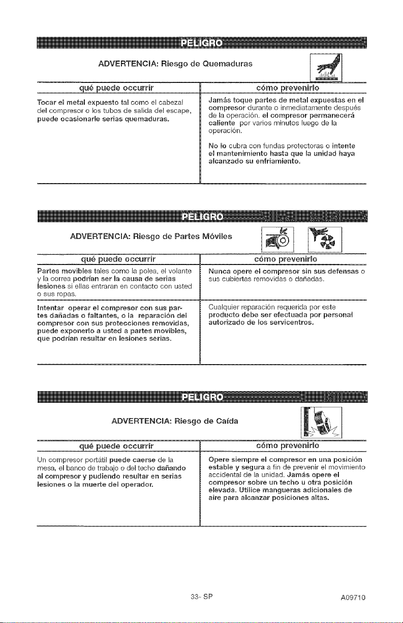
ADVERTENCIA: Riesgo de Quernaduras
qu_ puede occurrir
Tocar el metal expuesto tal come el cabezal
de! compresor o los tubes de salida de! escape,
puede ocaeionarie seriae quemaduras.
c6mo preveniHo
Jam_s toque partee de metal e×pueetas en eU
compresor durante o inmediatamente despues
de la ope_aci6n, eUcompreeor permanecer_
caliente pot vados minutos [uego de la
operaci6n.
No Uocubra con fundas protectoras o intente
el mantenimiento haeta que la unidad haya
alcanzado sa enfriamiento=
ADVERTENCIA: Riesgo de Partes M6vHes _ [_
qub puede occurrir c6mo preveniHo
Rartee movibiee tales como _a po]ea, el vo_ante Nunca opere eB compreeor sin eus defensas o
y la cor_a podr_an set Uanausa de eeriae sus cubiertas removidas o da[tadas.
Ueeiones si elias entraran en contacto con usted
o sus mpas_
Intentar operar el compresor con sus par- Cualquier repa_ci6n requerida por este
tes da_adas o faUtantee, o Ua reparaci6n deU producto debe sew efentuada pot personal
compresor con sue protecciones removidas, autorizado de Uos serviceu'_troe_
paede e×ponermo a ueted a partee movibles,
que podr_an resaltar en Uesiones seriae.
ADVERTENCIA: Riesgo de Ca_da Ii _'_", I
qu6 puede occurrir
Un compr÷sor portatil puede caerse de la
mesa, el banco de trabajo odel techo daSando
al nomp_sor y pudiendo reeuUtar en serias
Ueeiones o la mue_te deU operador.
c6mo prevenirmo
Opere eiempre eUcompreeor en una posici6n
estabUe y segura a fin de pr_venir el movimiento
accidenta_ de la unidad. Jam_e opere eU
compresor sobre an techo a otra poeici6n
e_evada. UtHice mangueras adicionaUee de
aire para aUcanzar poeicionee altae.
33= SP A09710
e iiiii,
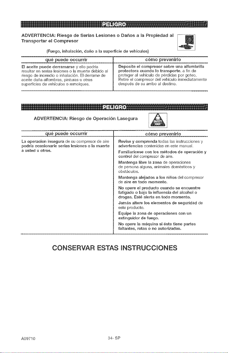
ADVERTENCIA: Riesgo de Sepias Lesiones o DaSos a la Propiedad al
Transportar el ¢ornpresor
(Fuego, hhaUaci6n, daSo a la superficie de vehicuUos)
qu_ puede occurrir c6mo preveniHo
EUaceite puede derramarse y ello podria Deposite e_ eomp_eso_ sobre usa aUfombriHa
resultar en serias _esiones o la muerte debido al protectora cuando Uotranspo_te, a fin de
rissgo de incendio o inha_aci6n. E! derrame de proteger a_vehicu]o de perdidas por goteo,
aceite daSa alfombras, pinturas u otras Retire e_compr_sor del vehicu_o inmediatamente
superficies de vehicu_os o remolques, despu6s de su arribo a{ destino.
ADVERTENCIA: Riesgo de Operaci6n Lasegura ,_ i
q u_ puede occurrir
La operacion insegura de su compresor de airs
pod_a oeasioearUe sepias lesiones o la mue_te
a usted u ethos,
c6mo preveniHo
Revise y comprenda todas las instrucciones y
advertencias contenidas en este manual
FamiHar{cese con los m_todos de operaci6n y
coetrom de! compresor de aire.
Mantenga libre la zona de operaciones
de persona alguna, animales dom_sticos y
obst_cu_os.
Mantenga aUejados a los niSos del compresor
de aire en todo memento.
No opere eUproducto eaando se eneaentre
fatigado o bajo Uainfluencia deU aUeohoU o
drogas, Est_ a[erta ee todo momento,
Jambs aUtere los eiementoa de segaridad de
este producto.
Eqaipe [a zona de ope_aciones con un
e×tinguidor de fuego.
No opere Uamaqaina si _sta tiene pastes
faRtantes, rotas o no autorizadas,
CONSERVAR ESTAS mNSTRUCCmONES
A09710 34- SP
Familiadcese con los siguientes t6rminos,
antes de operar la unidad:
CFM: (Cubic feet per minute) Pies cObicos
pot minuto.
SCFM: (Stardard cubic feet per minute)
Pies c0bicos est_ndar pot minuto; una
unidad de medida que permite medir la
cantidad de entrega de aire.
PSIG: (Pound per square inch) Libras por
pulgada cuadrada.
ASME: American Society of Mechanical
Engineers (Sociedad Americana de
Ingenieros MecAnicos); hecho probado
inspeccionado y registrado en
cumplimiento de los estAndares de la
ASME.
Cddigo de certificaci6n: Los productos
que usan una o mAs de las siguientes
marcas: UL, CUL, ETL, CETL, han side
evaluados per OSHA, laboratories
independientes certificados en seguridad,
y reOnen los estAndares suscriptos per los
laberatorios dedicados a la certificaci6n
de la seguridad.
Presi6n minima de eorte: Cuando el
motor esta apagado, la presi6n del tanque
de aire baja a medida que usted contin0a
usando su accesorio. Cuando la presi6n
del tanque baja al valor fijado en fAbrica
come punto bajo, el motor volvera a
arrancar automaticamente. La presi6n
baja a la cual el motor arranca
autom_ticamente, se llama presi6n
"minima de corte".
Presi6n m;_xima de eorte: Cuando un
compresor de aire se enciende y
comienza a funcionar, la presiOn de
aire en el tanque comienza a aumentar.
Aumenta hasta un valor de presiOn alto
fijado en f&brica antes de que el motor
automSticamente se apague protegiendo
a su tanque de aire de presiones mSs
altas que su capacidad. La presiOn alta a
la cual el motor se apaga se llama presi6n
"m_xima de corte".
Rarnal: Circuito el6ctrico que transporta
electricidad desde el panel de control
hasta el tomacorriente.
Esta unidad es suficiente para abastecer de energia electrica a los siguientes accesorios. Estos
se encuentran disponibles a traves del catAIogo para herramientas el_ctricas y manuales, en
cualquiera de los comercios que mantiene la ltnea completa de SEARS.
Aceesorios e Lubricadores de niebla de aceite
,, Filtro en Ifnea ,, Manguera de aire: 1/4 plug., 3/8 plug.
e Entrada de aire a neumSticos o 1/2 plug. D.I. en varias medidas
,, Juegos de conectores rSpidos (varies
tamales) RefiCrase al grafico de selecci6n ubicado
,, Reguladores de presiOn de aire sobre la unidad, para elegir el tipo de
herramienta que esta unidad es capaz de
hacer funcionar.
O D - _ O
Esta bomba compresora de aire es
capaz de funcionar continuamente, sin
embargo para prolongar la vida Otil de
su compresor de aire se recomienda
mantener un ciclo promedio de servicio
que oscile entre el 50% y el 75%; ello
significa que la bomba compresora no
deber[a trabajar m_s de 30 a 45 minutes
per hera.
35-SP A09710
Contenido de macaja
1= Compresor de aire
2= Ruedas
2= Pernos con resalto, 3/8-16 pulg.
2= Tuercas hexagonales, 3/8-16 pulg.
2= Parachoques de goma
2= Tornillos, 1/4=20 x 3/4 pulg.
Herramientas necesarias para em
ensambie
1 - Ilave de tubo o de boca de 9/16 pulg.
(14 mm)
1 - Ilave de tubo o de boca de 1/2 pulg.
(13 mm)
Desempaque
1. Retire todo el material de empaque
dejando al compresor de aire sobre
la tarima.
2. Retire y descarte los (4) tornillos que
sostienen al compresor de aire en la
tarima.
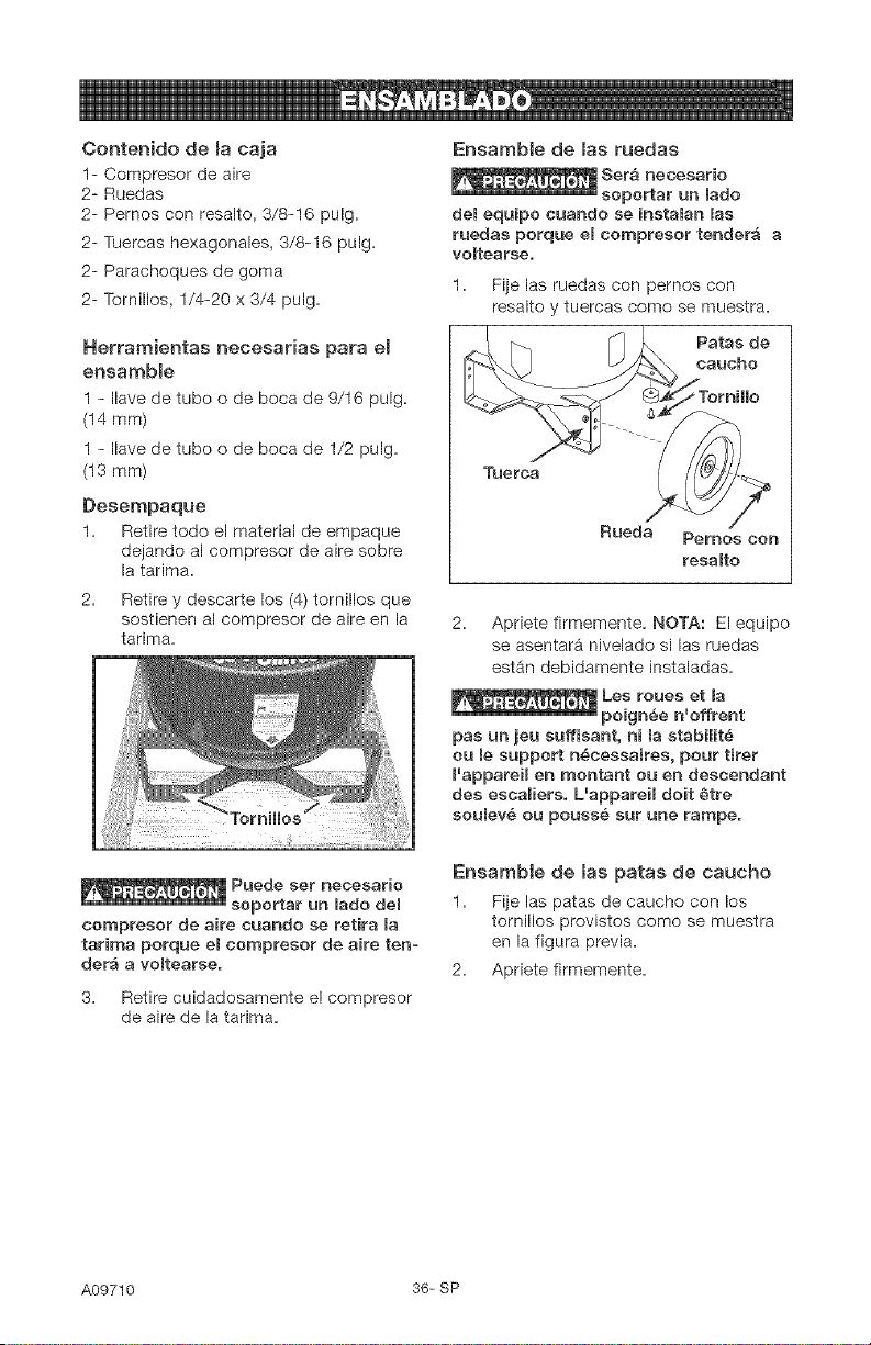
Ensamble de las ruedas
del equipo cuando se instalan las
ruedas porque el compresor tender_ a
voltearse.
l a Fije las ruedas con pernos con
resalto y tuercas como se muestraa
Paras de
oauoho
Rueda Pernos con
resalto
2. Apriete firmemente. NOTA: El equipo
se asentarA nivelado si las ruedas
estAn debidamente instaladas.
pas un jeu suffisant, ni la stabilit_
ou le support n_cessaires, pour tirer
I'appareil en montant ou en descendant
des escaliers. L'appareil doit #tre
soulev_ ou pouss_ sur une rampe.
_ Puede set neoesario
soportar un madodel
compresor de aire cuando se retira la
tarima porque eBcompresor de aire ten-
der_ a voBtearse.
3= Retire cuidadosamente el compresor
de aire de la tarimaa
Ensamble de las patas de caucho
l a Fije las patas de caucho con los
tornillos provistos como se muestra
en la figura previaa
2a Apriete firmementea
A09710 36= SP
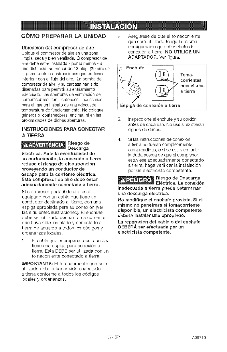
COMO PREPARAR LA UNIDAD 2. AsegOrese de que el tomacorriente
Ubicaci6n del compresor de aire
Ubique al compresor de aire en una zona
limpia, seca y bien ventilada. El compresor de
aire debe estar instalade - por le menos - a
una distancia no menor de 12 plug. (30 cm) de
la pared u otras obstrucciones que pudiesen
interferir con el flujo del aire. La bomba del
compresor de aire y su carcasa han sido
diseSadas para permitir su enfriamiento
adecuado. Las aberturas de ventilaci6n del
compresor resultan - entonces - necesarias
para el mantenimiento de una adecuada
temperatura de funcionamiento. No coloque
g_neros o contenedores, encima, ni en las
proximidades de dichas aberturas.
INSTRUCCIONES PARA CONECTAR
A TIERRA
Riesgo de
Descarga
EB_etrica. Ante la eventualidad de
un cortocircuito, la conexi6n a tierra
reduce el riesgo de electrocuci6n
proveyendo un conductor de
escape para la eorriente eB_ctriea.
Este cornpresor de aire debe estar
adecuadarnente conectado a tierra.
El compresor port&til de aire est_
equipado con un cable que tiene un
conductor destinado a tierra, con una
espiga apropiada para su conexi6n (vet
las siguientes ilustraciones). El enchufe
debe ser utilizado con un toma corriente
que haya side instalado y conectado a
tierra de acuerdo a todos los c6digos y
ordenanzas locales.
que serA utilizado tenga la misma
configuraci6n que el enchufe de
conexi6n a tierra. NO UTILIOE UN
ADAPTADOR. Ver figura.
Enchufe _[_ Tomao
corrientes
conectados
a tierra
/
Espiga de conexidn a tierra
3. Inspeccione el enchufe y su cord6n
antes de cada uso. No use si existieran
signos de dados.
4. Si las instrucciones de conexi6n
a tierra no fueran completamente
comprendidas, o si se estuviera ante
la duda acerca de que el compresor
estuviese adecuadamente conectado
a tierra, haga verificar la instalaci6n
per un electricista competente.
_ Riesgo de Descarga
El_ctrica. La conexi6n
inadecuada a tierra puede determinar
una desearga el_etriea.
No rnodifique el enchufe provisto. Si el
misrno no penetrara el tornacorriente
disponible, un electricista competente
deber& instalar uno apropiado.
La reparaci6n del cable o del enchufe
DEBERA set efectuada per un
electrieista eornpetente.
El cable que acompafia a esta unidad
tiene una espiga para conexiOn a
tierra. Esta DEBE ser utilizada con un
tomacorriente conectado a tierra.
IMPORTANTE: El tomacorriente que ser5
utilizado deberA haber sido conectado
a tierra conforme a todos los cOdigos
locales y ordenanzas.
37-SP A09710

CabBes de extensi6n el_ctrJca
No se recomienda la utilizaci6n de cables
de e×tensi6n el6ctrica. El uso de cables
de extensi6n el6ctrica originara una
caida de tensi6n, Io que determinar_ una
p6rdida de potencia del motor asf como
su recalentamiento. En lugar de utilizar un
cable de extensi6n el¢ctrica, incremente
el alcance de la manguera de aire dentro
de la zona de trabajo, aFiadi6ndole otro
largo de manguera a su extremo. Conecte
los largos adicionales de manguera de
acuerdo a su necesidad.
Si - no obstante - debe utilizarse una
extensi6n de cable, asegOrese de que:
,, La extensi6n el6ctrica de 3
conductores, tenga un enchufe de
conexi6n a tierra de 3 hojas, y que
exista un recept_culo que acepte el
enchufe del producto.
,, Est6 en buenas condiciones.
No mAs largo que 15,2 m (50 pies).
,, Calibre 12 (AWG) o mayor. (La
medida de los cables se incrementa
a medida que su nOmero ordinal
decrece. 10 y 8 AWG pueden ser
usados tambi6n. NO USE 14 N116
AWG).
Protecci6n del voltaje y del circuito
Acerca del voltaje y la minima cantidad de
circuitos requeridos, refi6rase al cuadro de
especificaciones.
compresores de aire pueden set
operados en un circuito de 15 A,
siempre que se cumplan las siguientes
condiciones:
1. Que el voltaje suministrado a trav6s de
los ramales del circuito sea de 15 A.
2. Que el circuito no sea utilizado para
alimentar ninguna otra necesidad
el6ctrica.
3. Que los cables de extensi6n cumplan
con las especificaciones.
4. El circuito cuenta con un disyuntor de
15 amperios o un fusible de acci6n
retardada de 15 amperios. NOTA:
Si el compresor est9 conectado a un
circuito protegido por fusibles, use
s61o fusibles de acci6n retardada.
Los fusibles de aeci6n retardada
deben estar mareados con la letra
"D" en Canad_ y "T" en EE.UU.
Si cualquiera de las condiciones
enumeradas no pudiese ser cumplida, o si
el funcionamiento del compresor causara
reiteradas interrupciones de la energia con
la que se Io alimenta, podria set necesario
operar al mismo desde un circuito de 20
A. Para ello no ser_ necesario cambiar su
cable de limentaci6n.
A09710 38-SP
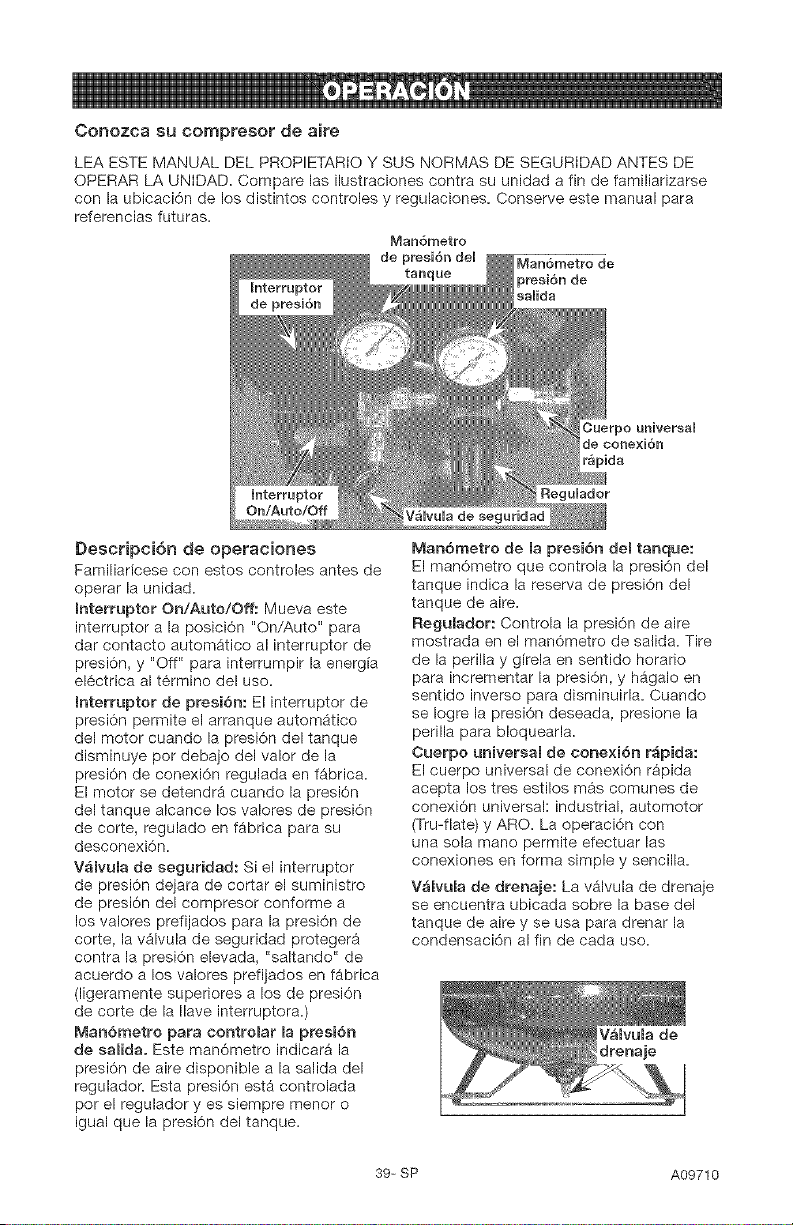
Conozca su com_resor de Qir@
LEA ESTE MANUAL DEL PROPIETARiO Y SUS NORMAS DE SEGURiDAD ANTES DE
OPERAR LA UNIDAD. Compare las ilustraciones contra su unidad a fin de familiarizarse
con la ubicaci6n de los distintos controles y regulaciones. Conserve este manual para
referencias futuras.
Man6metro
de
tanque
Man6metro de
presi6n de
saUida
Descripci6n de operaciones
Familiadcese con estos controles antes de
operar la unidad.
mnterruptor On/Auto/Off: Mueva este
interruptor a la posici6n "On/Auto" para
dar contacto automAtico al interruptor de
presi6n, y "Off" para interrumpir la energia
el6ctrica al t6rmino del uso.
Interruptor de presi6n: El interruptor de
presi6n permite el arranque autom_tico
del motor cuando la presi6n del tanque
disminuye por debajo del valor de la
presi6n de conexi6n regulada en f_brica.
El motor se detendr_ cuando la presi6n
del tanque alcance los valores de presi6n
de corte, regulado en f_brica para su
desconexi6n.
V_lvuRa de seguridad: Si el interruptor
de presi6n dejara de cortar el suministro
de presi6n del compresor conforme a
los valores prefijados para la presi6n de
corte, la v_lvula de seguridad proteger_
contra la presi6n elevada, "saltando" de
acuerdo a los valores prefijados en fgbrica
(ligeramente superiores a los de presi6n
de corte de la Ilave interruptora.)
Man6metro para controBar mapresi6n
de saRida. Este man6metro indicar_ la
presi6n de aire disponible a la salida del
regulador. Esta presi6n estA controlada
por el regulador yes siempre menor o
igual que la presi6n del tanque.
Cuerpo universal
de cone×i6n
r_pida
Man6metro de la presi6n del tanque:
El man6metro que controla la presi6n del
tanque indica la reserva de presi6n del
tanque de aire.
Regulador: Controla la presi6n de aire
mostrada en el man6metro de salida. Tire
de la perilla y gfrela en sentido horatio
para incrementar la presi6n, y hggalo en
sentido inverso para disminuirla. Cuando
se Iogre la presi6n deseada, presione la
perilla para bloquearla.
Cuerpo universaB de conexi6n r_pida:
El cuerpo universal de conexi6n r_pida
acepta los tres estilos m_s comunes de
conexi6n universal: industrial, automotor
(Tru-flate) y ARO. La operaci6n con
una sola mano permite efectuar las
conexiones en forma simple y sencilla.
V_lvula de drenaje: La vAIvula de drenaje
se encuentra ubicada sobre la base del
tanque de aire y se usa para drenar la
condensaci6n al fin de cada uso.
39-SP A09710
Sistema de enfriamiento (no
mostrado}: Este compresor contiene
un sistema de avanzada para el
control de enfriamiento. En el nL_cleo
de este sistema de enfriamiento hay
un ventilador especialmente diseFiado.
Resulta perfectamente normal - para
este ventilador - soplar aire en grandes
cantidades a trav6s de los orificios de
ventilaciSn. De tal manera se podr_ saber
que el sistema de enfriamiento trabaja
cuando el aire esta siendo expelido.
Bomba de compresi6n deR aire (no
mostrada): Comprime el aire dentro del
tanque. El aire de trabajo no se encuentra
disponible hasta que el compresor haya
alcanzado a Ilenar el tanque hasta un nivel
de presi6n per encima del requerido para
la salida del aire.
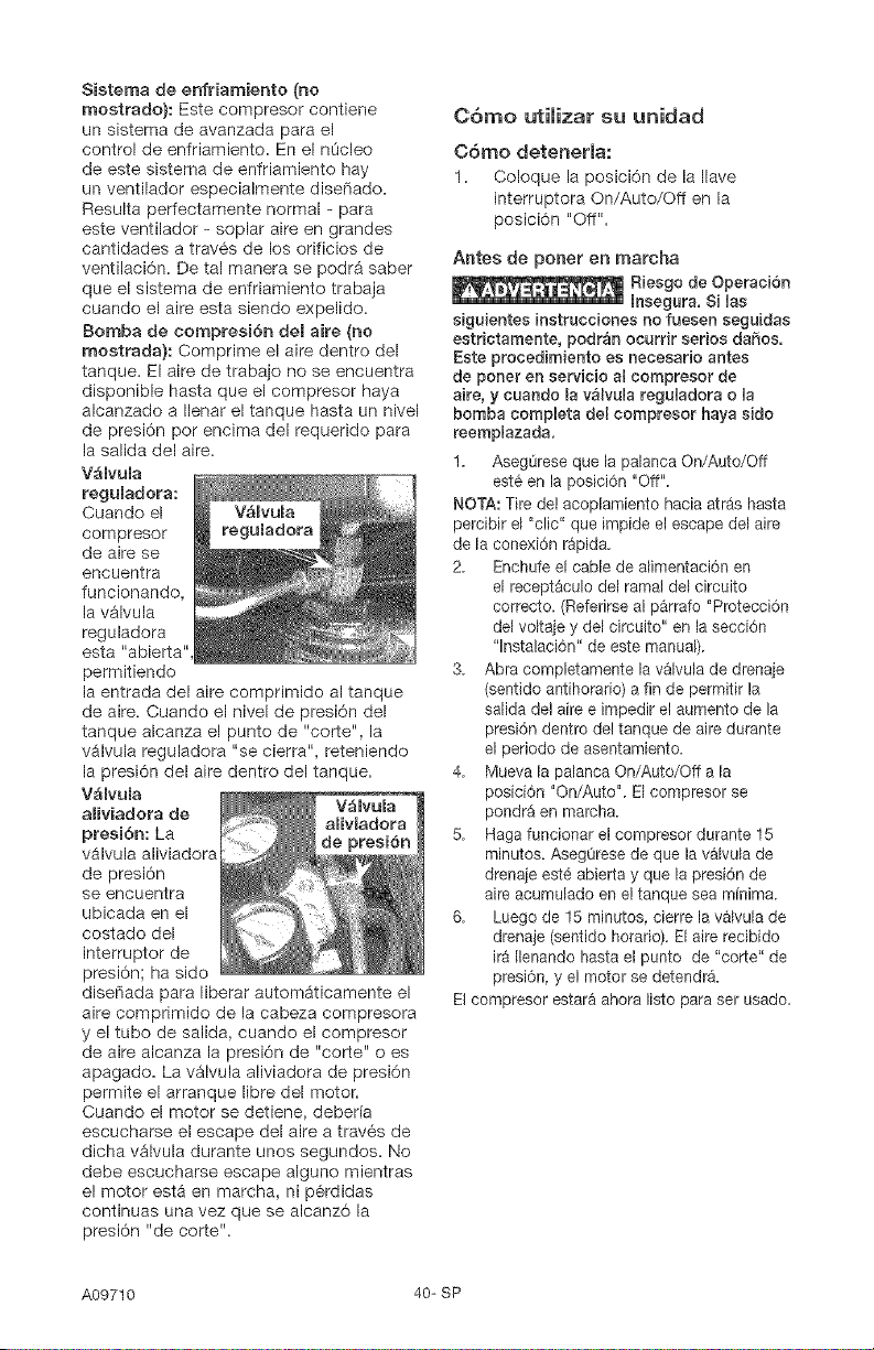
V_lvula
reguladora:
Cuando el
compresor
de aire se
encuentra
funcionando,
la v_lvula
reguladora
esta "abierta"
permitiendo
la entrada del aire comprimido al tanque
de aire. Cuando el nivel de presi6n del
tanque alcanza el punto de "corte", la
vAIvula reguladora "se cierra", reteniendo
la presi6n del aire dentro del tanque.
V_lvula
aliviadora de V_lvula
aliviadora
presi6n: La de presibn
vAIvula aliviadora
de presi6n
se encuentra
ubicada en el
costado del
interrupter de
presi6n; ha sido
diseFiada para liberar automAticamente el
aire comprimido de la cabeza compresora
y el tube de salida, cuando el compresor
de aire alcanza la presi6n de "corte" o es
apagado. La v_lvula aliviadora de presi6n
permite el arranque libre del motor.
Cuando el motor se detiene, deber[a
escucharse el escape del aire a trav6s de
dicha v_lvula durante unos segundos. No
debe escucharse escape alguno mientras
el motor est& en marcha, ni p6rdidas
continuas una vez que se alcanz6 la
presi6n "de corte".
C6mo utilizar su unidad
C6mo detenerla:
1. Coloque la posici6n de la Ilave
interruptora On/Auto/Off en la
posici6n "Off".
Antes de poner en marcha
Riesgo de Operaci6n
Insegura. Si Uas
siguientes instrucciones no fuesen seguidas
estrictamente, podr_n ocurrir serios daSos.
Este procedimiento es necesario antes
de poner en servicio al eompresor de
aire, y cuando la v_lvula reguladora o la
bomba completa del compresor haya sido
reemplazada.
1. AsegL_reseque la palanca On/Auto/Off
est& en la posici6n "Off".
NOTA: Tire de! acoplamiento hacia atras hasta
percibir el "clic" que impide et escape del aire
de la conexiSn r_pida.
2. Enchufe el cable de alimentaciOn en
el recept&culo del ramal del circuito
correcto. (Referirse al p&rrafo "Protecci6n
del voltaje y del circuito" en la secci6n
"lnstalaciSn" de este manual).
3. Abra cempletamente la v&lvula de drena}e
(sentido antihorario) a fin de permitir la
salida de! aire e impedir el aumento de la
presi6n dentro de! tanque de aire durante
el periodo de asentamiento.
4. Mueva la palanca On/Auto/Off a la
posici6n "On/Auto". El compresor se
pondr_ en marcha.
5. Haga funcionar el compresor durante 15
minutos. AsegOrese de que la v_lvula de
drenaje est_ abierta y que la presi6n de
aire acumulado en el tanque sea minima.
6. Luego de 15 minutes, cierre la v&lvula de
drenaje (sentido horario). El aire recibido
ira Ilenando hasta et punto de "corte" de
presi6n, y el motor se detendra.
El compresor estar& ahora Iisto para set usado.
A09710 40-SP
Antes de cada puesta en marcha:
1, Coloque el interrupter On/Auto/Off en
la posici6n "Off" y cierre el regulador de
aire.
2. Tire de la perilla del regulador, gire en
sentido antihorario hasta el limite. Empuje
la perilla hasta su posicbn b!ocante.
3. Conecte la manguera y accesorios.
NOTA: Tanto la manguera come los
aecesorios requerir&n un enehufe de
conexi6n r_pida si la salida del aire est_
equipada con un z6calo de conexi6n
rapida.
Riesgo de Explosi6n.
Demasiada presi6n
de aire podr_ set la causa de riesgo de
explosi6n. Vedfiqae los valores de m_xima
presi6n dados pot el fabricante de las
herramientas neumgticas y los accesofios.
La presi6n de salida del regulador jam_s
debe exceder los valores de m_xima
presi6n especificados.
C6mo poner en marcha:
1. Mueva la palanca On/Auto/Off a la
posiciSn "On/Auto" y deje que se
incremente la presi6n del tanque. El
motor se detendr& una vez alcanzado el
valor de presi6n "de core" del tanque.
2. Tire de la perilla del regulador y gire
en sentido horario para incrementar la
presi6n. Cuando el valor deseado de
presi6n sea Iogrado, presione la perilla
hasta su posici6n blocante. El compresor
estara listo para set usado.
NOTA: Opere siempre el compresor de aire en
_reas bien ventiladas, libres de gasolina u otras
emanaciones combustibles. Si et compresor
sera utilizado para utilizar un rociador_NO
Io coloque en las cercanias de la zona de
rociado.
El compresor estate. Iisto para set usado.
41-SP A09710
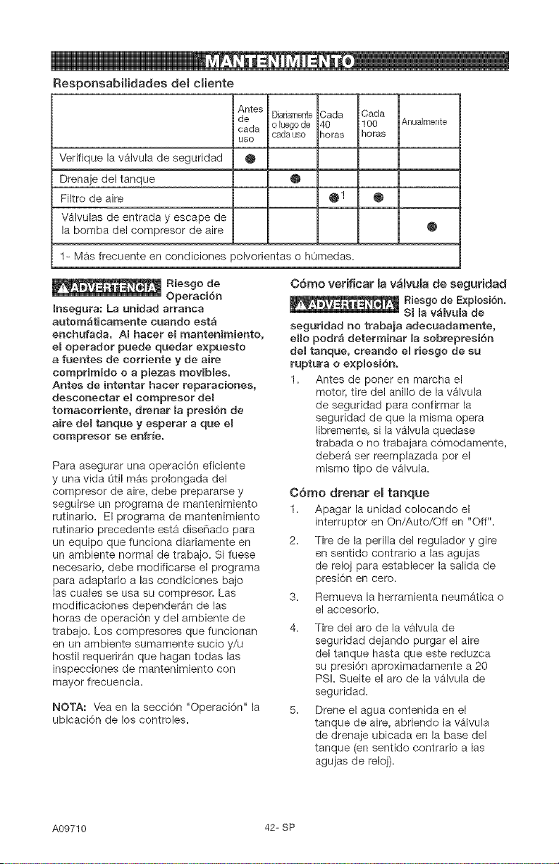
Responsabilidades dem cliente
Antes
de Diariamente Carla Carla
o luego de 40 100
carla
cads use Betas horas
use
Verifique la v_lvula de seguridad •
Drenaje del tanque @
Filtro de aire O 1 O
V_lvulas de entrada y escape de
la bomba del compresor de aire
AnuaJmente
O
1- Mas frecuente en condiciones polvorientas o hOmedas.
Riesgo de
Operaci6n
mnsegura: La unidad arranca
autom_ticamente cuando est&
enehufada. ABhacer eBmantenimiento,
el operador puede quedar e×puesto
a fuentes de eorriente y de airs
comprimido o a piezas movibles.
Antes de intentar hacer reparaeiones,
desconectar eBeompresor deR
tomacorriente, drenar la presi6n de
airs del tanque y esperar a que el
compresor se enfr_e.
Para asegurar una operaciSn eficiente
y una vida L_tilm&s prolongada del
compresor de aire, debe prepararse y
seguirse un programa de mantenimiento
rutinario. El programa de mantenimiento
rutinario precedente est_ diseFiado para
un equipo que funciona diariamente en
un ambiente normal de trabajo. Si fuese
necesario, debe modificarse el programa
para adaptarlo alas condiciones bajo
las cuales se usa su compresoc has
modificaciones dependergn de las
heras de operaci6n y del ambiente de
trabajo. Los compresores que funcionan
en un ambiente sumamente sucio y/u
hestil requerir_n que hagan todas las
inspecciones de mantenimiento con
mayor frecuencia.
NOTA: Vea en la secci6n "Operaci6n" la
ubicaci6n de los controles.
C6mo verificar mav_mvula de seguridad
Riesgo de E×plosi6n.
Si la v_lvula de
seguridad no trabaja adeeuadamente,
e((o podr_ determinar (a sobrepresi6n
del tanque, ereando el riesgo de su
ruptura o e×plosi6n.
1. Antes de poner en marcha el
motor tire del anillo de la v_lvula
de seguridad para confirmar la
seguridad de que la misma opera
libremente, si la v_lvula quedase
trabada o no trabajara c6modamente,
deber_ set reemplazada per el
mismo tipo de valvula.
C6mo drenar el tanque
1. Apagar la unidad colocando el
interrupter en On/Auto/Off en "Off"=
2. Tire de la perilla del regulador y gire
en sentido contrario a las agujas
de reloj para establecer la salida de
presi6n en cero.
Remueva la herramienta neumatica o
el accesorio.
3.
4. Tire del are de la valvula de
seguridad dejando purgar el aire
del tanque hasta que este reduzca
su presi6n aproximadamente a 20
PSI. Suelte el are de la vb.lvula de
seguridad.
Drene el agua contenida en el
tanque de aire, abriendo la v_lvula
de drenaje ubicada en la base del
tanque (en sentido contrario alas
agujas de reloj).
A09710 42-SP
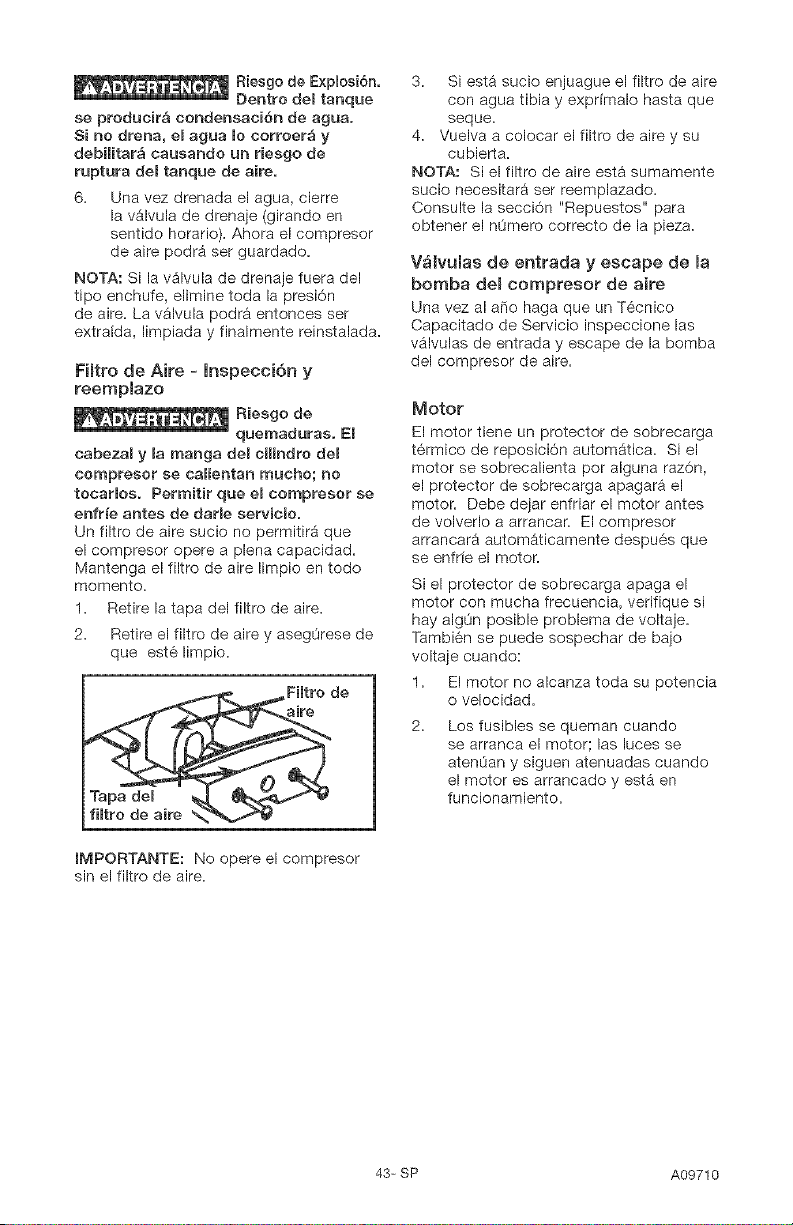
Riesgo de E×plosi6n.
Dentro de[ tanque
se producir& condensaci6n de agua.
Si no drena, el agua Io corroer_ y
debilitar_ causando un riesgo de
ruptura de[ tanque de aire.
6. Una vez drenada e[ agua, cierre
la v_lvula de drenaje (girando en
sentido horatio). Ahora el compresor
de aire podrA ser guardado.
NOTA: Si la v_lvula de drenaje fuera del
tipo enchufe, elimine toda la presi6n
de aire. La v_lvula podr& ententes set
extrafda, limpiada y finalmente reinstalada.
Filtro de Aire - lnspecci6n y
reemplazo
Riesgo de
quemaduras. E[
cabeza[ y [a manga de[ c[[[ndro de[
cempreser se ca[ientan touche; no
tecaHos. Permitir que el compresor se
enfrie antes de dar[e servieio.
Un filtro de aire sucio no permitir_ que
el compresor opere a plena capacidad.
Mantenga el filtro de aire limpio en todo
memento.
1. Retire la tapa del filtro de aire.
2. Retire el filtro de aire y asegOrese de
que est6 limpio.
_Fiffro de
aire
fiRro de aire _N,"_,_tJ
IMPORTANTE: No opere el compresor
sin el filtro de aire.
3. Siesta sucio enjuague el filtro de aire
con agua tibia y exprimalo hasta que
seque.
4. Vuelva a colocar el filtro de aire y su
cubierta.
NOTA: Si el filtro de aire est_ sumamente
sucio necesitar9 ser reemplazado.
Consulte la secci6n "Repuestos" para
obtener el n0mero correcto de la pieza.
V_tvulas de entrada y escape de la
bomba del compresor de aire
Una vez al are haga que un Tecnico
Capacitado de Servicio inspeccione las
v_lvulas de entrada y escape de la bomba
del compresor de aire.
Motor
El motor tiene un protector de sobrecarga
t6rmica de reposici6n automgtica. Si el
motor se sobrecalienta per alguna raz6n,
el protector de sobrecarga apagar_ el
motor. Debe dejar enfriar el motor antes
de volverlo a arrancar. El compresor
arrancar_ autom_ticamente despu6s que
se enfrfe el motor.
Si el protector de sobrecarga apaga el
motor con mucha frecuencia, verifique si
hay alg0n posible problema de voltaje.
Tambi6n se puede sospechar de bajo
voltaje cuando:
1. El motor no alcanza toda su potencia
o velocidad.
Los fusibles se queman cuando
se arranca el motor las luces se
atenOan y siguen atenuadas cuando
el motor es arrancado y esta en
funcionamiento.
43-SP A09710
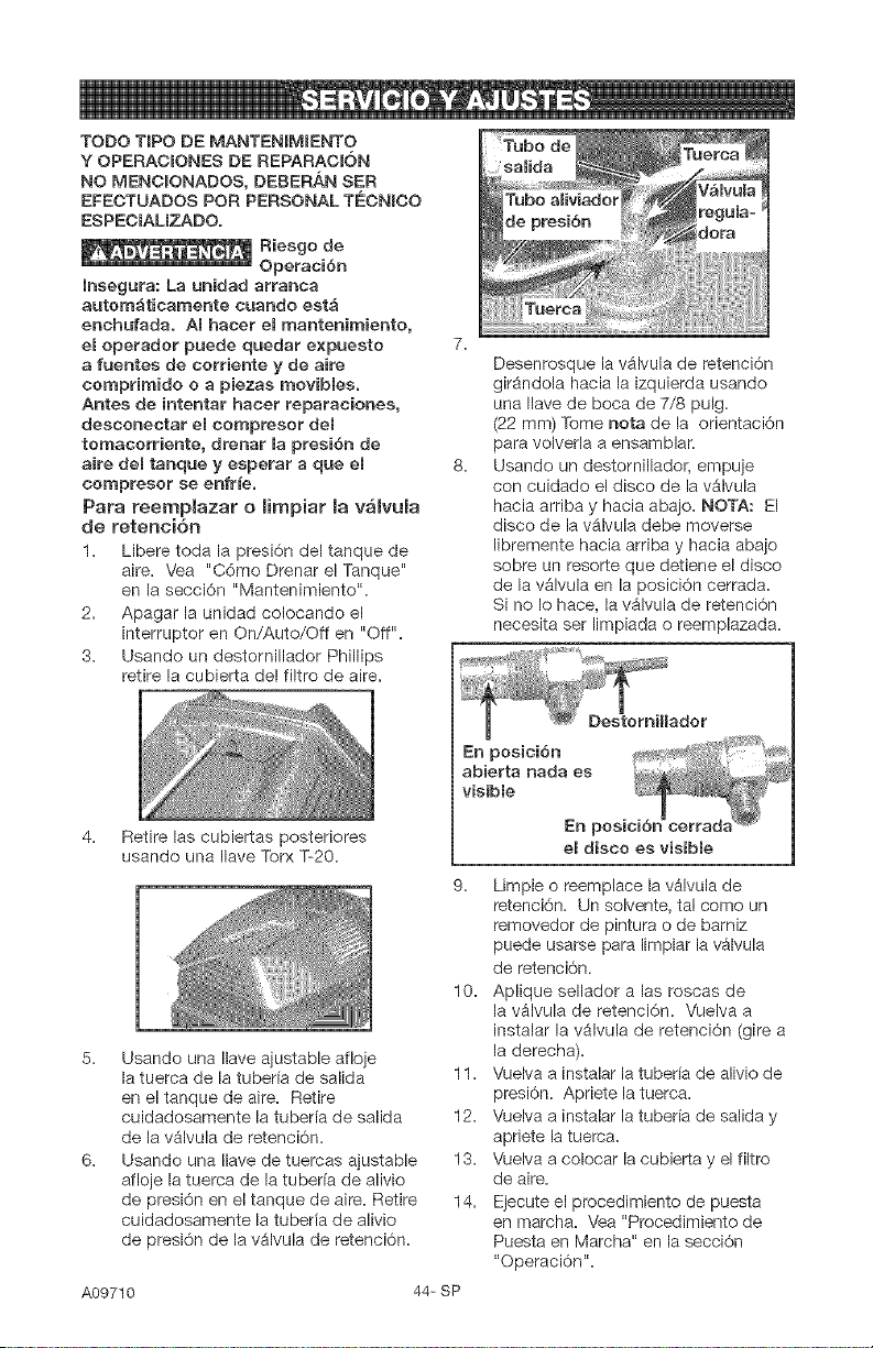
TODO T[PO DE MANTENIMIENTO
Y OPERACIONES DE REPARAC[6N
NO MENCIONADOS, DEBERAN SER
EFECTUADOS POR PERSONAL TECNICO
ESPE¢IALIZADO.
Riesgo de
Operaci6n
[nsegura: La unidad arranea
autom_ticamente cuando est&
enehufada. AI hacer e[ mantenirniento,
e[ operador puede quedar expuesto
a fuentes de corriente y de aire
comprirnido o a piezas movib[es.
Antes de intentar haeer reparaciones,
desconeetar el compresor del
tomacorriente, drenar [a presi6n de
aire de[ tanque y esperar a que e[
eompresor se enfr_e.
Para reemp[azar o [impiar [a v_[vu[a
de retenci6n
1. Libere toda la presi6n del tanque de
aire. Vea "CAme Drenar el Tanque"
en la secci6n "Mantenimiento".
2. Apagar la unidad colocando el
interruptor en On/Auto/Off en "Off".
3. Usando un destornillador Phillips
retire la cubierta del filtro de aire.
4. Retire las cubiertas posteriores
usando una Ilave Torx T-20.
5. Usando una Ilave ajustable afloje
la tuerca de la tuberia de salida
en el tanque de aire. Retire
cuidadosamente la tuberfa de salida
de la vAlvula de retenci6n.
6. Usando una Ilave de tuercas ajustable
afloje la tuerca de la tuberia de alivio
de presi6n en el tanque de aire. Retire
cuidadosamente la tuberfa de alivio
de presi6n de la vAIvula de retenci6n.
A09710
9. Limpie o reemplace la vAIvula de
retenci6n. Un solvente, tal como un
removedor de pintura o de barniz
puede usarse para limpiar la vAIvula
de retenci6n.
10. Aplique sellador alas roscas de
la vbJvula de retenci6n. Vuelva a
instalar la vAIvula de retenci6n (gire a
la derecha).
11. Vuelva a instalar la tuber[a de alivio de
presi6n. Apriete la tuerca.
12. Vuelva a instaiar la tuber[a de salida y
apriete la tuerca.
13. Vuelva a colocar la cubierta y el filtro
de aire.
14. Ejecute el procedimiento de puesta
en marcha. Vea "Procedimiento de
Puesta en Marcha" en la secci6n
"OperaciOn".
Desenrosque la vAIvula de retenci0n
gir_ndola hacia la izquierda usando
una Ilave de boca de 7/8 pulg.
(22 mm) Tome nora de la orientaci6n
para volverla a ensamblar.
Usando un destornillador, empuje
con cuidado el disco de la v_lvula
hacia arriba y hacia abajo. NOTA: El
disco de la vAIvula debe moverse
libremente hacia arriba y hacia abajo
sobre un resorte que detiene el disco
de la vglvula en la posici6n cerrada.
Si no Io hace, la v_lvula de retenci6n
necesita set limpiada o reemplazada.
e[ disco es visible
44- SP

Para reemplazar emregumador
1. Libere toda la presi6n del aire del
tanque. Vea "Drenaje del tanque" en
la secci6n "Mantenimiento".
2. Apagar la unidad colocando el
interrupter en On/Auto/Off en "Off".
3. Usando una Ilave de tuercas ajustable
retire el medidor de salida de presi6n
y la conexi6n r_pida del regulador
(si la tiene).
4. Extraiga el regulador.
6. Ensamble el regulador y ori6ntelo de
acuerdo a Io mostrado.
NOTA: La flecha indica el sentido del
flujo del aire. AsegOrese que est6
apuntando a la direcci6n en la que fluye
el aire.
Aplique cinta selladora de cariedas
sobre el niple del tube vertical.
7.
8.
Reaplique sellador de caPiedas al
man6metro de presi6n externa y a la
conexi6n rapida.
Rearme el man6metro de presi6n de
salida y el conector rapido. Oriente
el man6metro de salida para permitir
su lectura correctamente. Ajuste las
conexiones con a liar.
45-SP A09710
Antes de guardar su compresor de aire,
asegOrese de hacer Io siguiente:
1. Revise la secci6n "Mantenimiento"
de las p_ginas precedentes y ejecute
el mantenimiento programado de
acuerdo a la necesidad.
2. Apagar la unidad colocando el
interruptor en On/Auto/Off en "Off".
3. Gire el regulador en sentido
antihorario y fije la presi6n de salida
en cero.
4. Extraiga la herramienta neum_tica o
el accesorio.
5. Tire del anillo de la v_lvula de
seguridad permitiendo el purgado del
aire del tanque hasta que la presi6n
del mismo Ilegue aproximadamente
a 20 PSi. Suelte el anillo de la v_lvula
de seguridad.
6. Drene el agua del tanque de aire
abriendo la valvula de drenaje
ubieada en el fondo del tanque.
Riesgo de Explosi6n.
El agua se
condensa dentro del tanque de aire. Si
no se drena, ella
corroer_ debiHtando la paredes del
tanque de aire, originando un riesgo de
ruptura de sus paredes.
7. Una vez que el agua haya side
drenada, cierre la v_lvula de drenaje.
NOTA: Si la v_lvula de drenaje estuviese
enchufada, libere toda la presi6n de aire.
La v_lvula podrA ser extraida, limpiada y
luego reinstalada.
8. Proteja el cable el6ctrico y las
mangueras de aire de dafios (tales
come ser pisoteados o pasados per
encima). Enr611elos en forma floja,
alrededor de la manija del compresor.
(Si asf estuviese equipado).
9. Almacene el compresor de aire en un
sitio limpio y seco.
A09710 46-SP
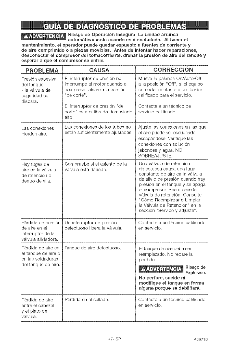
Riesgo de Operaci6n Insegura: La unidad arranca
autom&tieamente cuando est_ enehufada. Amhaeer el
mantenimiento, el operador puede quedar e×puesto a fuentes de corriente y
de aire comprimido o a piezas mevibles. Antes de intentar hacer reparaciones,
desconectar eRcompresor del tomacorriente, drenar la presi6n de aire del tanque y
esperar a que el compresor se enfrie.
PROBLEMA
Presi6n excesiva
del tanque
- la vAIvula de
seguridad se
dispara.
Las conexiones
pierden aire.
CAUSA
El interrupter de presi6n no
interrumpe al motor cuando el
compresor alcanza la presi6n
"de corte%
El interrupter de presi6n "de
corte" esta calibrado demasiado
alto.
Las conexiones de los tubes no
est_n suficientemente ajustadas.
Compruebe si el asiento de la
vAIvula est& daSado.
Hay fugas de
aire on la v_lvula
de retenci6n o
dentro de ella.
CORRECCION
[Vlueva la palanca On/Auto/Off
a la posici6n "Off", si el equipo
no corta, contacte a un t6cnico
calificado para el servicio.
Contacte a un t6cnico de
servicio calificado.
Ajuste las conexiones en las que
el aire puede ser escuchado
escapandose. Verifique las
conexiones con soluci6n
jabonosa y agua. NO
SOBREAJUSTE.
Una v_lvula de retenci6n
defectuosa causa una fuga
constante de aire on la v_lvula
de alivio de presi6n cuando hay
presi6n on el tanque y se apaga
el compresor. Reemplace la
valvula de retenci6n. Consulte
"C6mo Reemplazar o Limpiar
la V_lvula de Retenci6n" en la
secci6n "Service y adjuste%
P6rdida de presi6n Un interrupter de presi6n Contacte a un tecnico calificado
de aire en el defectuoso libera la valvula, en servicio.
interrupter de la
v_lvula aliviadora.
P6rdida de aire en Tanque de aire defectuoso.
P6rdida on el sellado.
el tanque do aire o
on las soldaduras
del tanque de aire.
P6rdida de aire
entre el cabezal
y el plato de
v_lvula.
El tanque de aire debe ser
reemplazado. No repare la
perdida.
Riesgo de
Explosi6n.
No perfore, suelde ni
modifique el tanque en forma
alguna porque se debilitate.
Contacte a un tecnico calificado
en servicio.
47-SP A09710
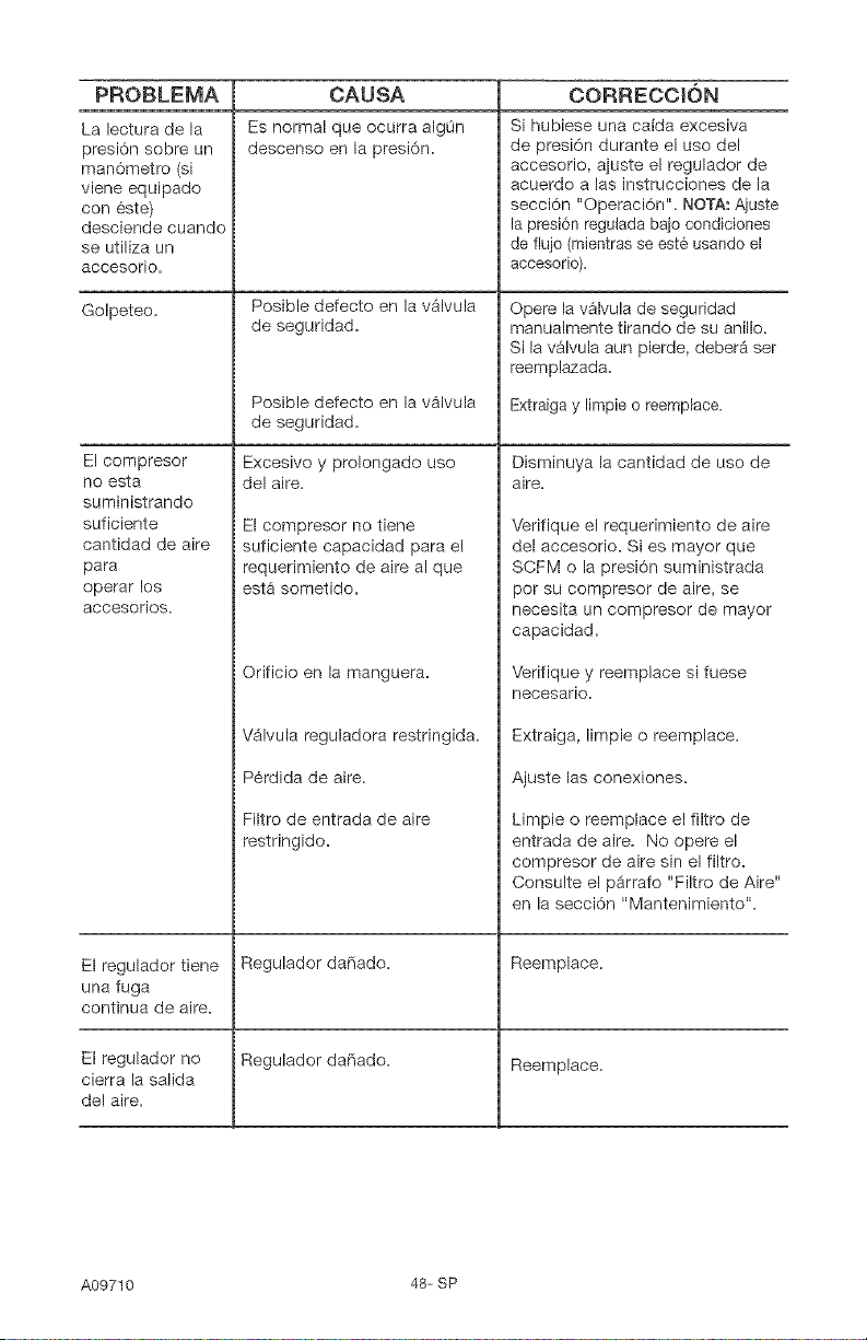
PROBLEMA
La lectura de la
presi6n sobre un
man6metro (si
viene equipado
con 6ste)
desciende cuando
se utiliza un
accesorio.
Golpeteo.
El compresor
no esta
suministrando
suficiente
cantidad de aire
para
operar los
accesorios.
El regulador tiene
una fuga
continua de aire.
El regulador no
cierra la salida
del aire.
CAUSA
Es normal que ocurra algOn
descenso en la presi6n.
Posible defecto en la v_lvula
de seguridad.
Posible defecto en la v&lvula
de seguridad.
Excesivo y prolongado uso
del aire.
El compresor no tiene
suficiente capacidad para el
requerimiento de aire al que
esta sometido.
Orificio en la manguera.
V$1vula reguladora restringida.
P6rdida de aire.
Filtro de entrada de aire
restringido.
Regulador daPiado.
Regulador da_ado.
CORRECCION
Si hubiese una caida excesiva
de presi6n durante el uso del
accesorio, ajuste el regulador de
acuerdo a las instrucciones de la
secci6n "Operaci6n". NOTA_Ajuste
la presi6n regulada ba}o condiciones
de flujo (mientras se est6 usando et
accesorio).
Opere la valvula de seguridad
manualmente tirando de su anillo.
Si la v_lvula aun pierde, deber_ set
reemplazada.
Extraiga y Iimpie o reemplace.
Disminuya la cantidad de uso de
aire.
Verifique el requerimiento de aire
del accesorio. Si es mayor que
SCFM o la presi6n suministrada
9or su cornpresor de aire, se
necesita un compresor de mayor
capacidad.
Verifique y reemplace si fuese
neoesario.
Extraiga, limpie o reemplace.
Ajuste las conexiones.
Limpie o reemplace el filtro de
entrada de aire. No opere el
compresor de aire sin el filtro.
Consulte el p_rrafo "Filtro de Aire"
en la secci6n "Mantenimiento".
Reemplace.
Reemplace.
A09710 48- SP
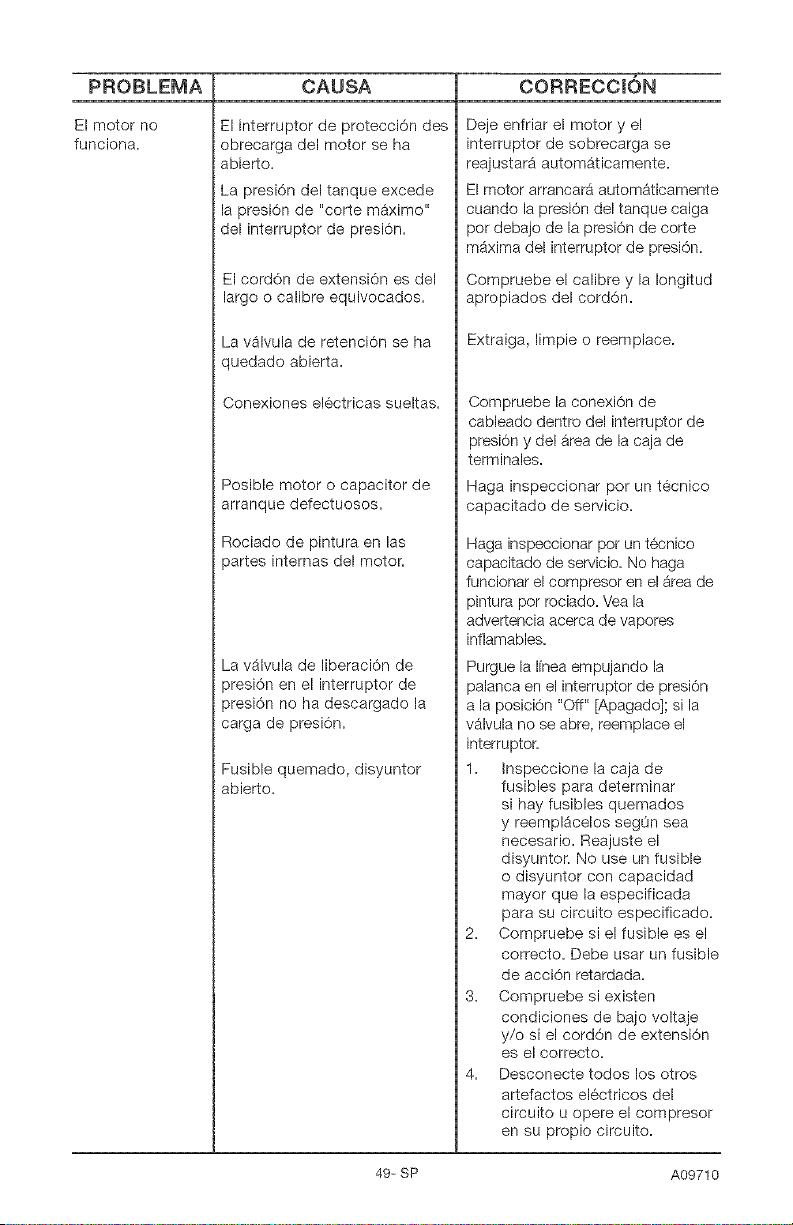
PROBLEMA
El motor no
funciona.
CAUSA CORRECCION
El interrupter de protecci6n des
obrecarga del motor se ha
abierto.
La presi6n del tanque excede
la presi6n de "corte m_ximo"
del interruptor de presi6n.
El cord6n de extensi6n es del
largo o calibre equivocados.
La valvula de retenci6n se ha
quedado abierta.
Conexiones el6ctricas sueltas.
Posible motor o capacitor de
arranque defectuosos.
Rociado de pintura en las
)artes internas del motor.
La valvula de liberaci6n de
)resi6n en el interruptor de
)resi6n no ha descargado la
carga de presi6n.
Fusible quemado, disyuntor
abierto.
Deje enfriar el motor y el
interruptor de sobrecarga se
reajustar9 autom_ticamente.
El motor arrancar9 autom_ticamente
cuando la presi6n del tanque caiga
per debajo de la presi6n de corte
m_xima del interruptor de presi6n.
Compruebe el calibre y la Iongitud
apropiados del cord6n.
Extraiga, limpie o reemplace.
Compruebe la conexi6n de
cableado dentro del interrupter de
presi6n y del _rea de la caja de
terminales.
Haga inspeccionar pot un tecnico
capacitado de servicio.
Haga inspeccionar por un t6cnico
capacitado de sePdcio. No haga
funcionar el compresor en el _rea de
pintura pot rociado. Vea la
advertencia acerca de vapores
inflamables.
Purgue la Ifnea empujando la
palanca en el interrupter de presi6n
a la posici6n "Off" [Apagado]i si la
v_lvula no se abre, reemplace el
interruptor.
1. Inspeccione la caja de
fusibles para determinar
si hay fusibles quemados
y reemplacelos segOn sea
necesario. Reajuste el
disyuntor. No use un fusible
o disyuntor con capacidad
mayor que la especificada
para su circuito especificado.
2. Compruebe si el fusible es el
correcto. Debe usar un fusible
de acci6n retardada.
3. Compruebe si existen
condiciones de bajo voltaje
y/o si el cord6n de extensi6n
es el correcto.
4. Desconecte todos los otros
artefactos el6ctricos del
circuito u opere el compresor
en su propio circuito.
49- SP A09710

A09710 50-SP
Repair Protection Agreements
Congratulations on making a smart
purchase. Your new Craftsman C_)product
is designed and manufactured for years
of dependable operation. But like all
products, it may require repair from time
to time. That's when having a Repair
Protection Agreement can save you
money and aggravation.
Purchase a Repair Protection Agreement
now and protect yourself from unexpected
hassle and expense.
Here's what's included in the Agreement:
[] Expert service by our 12,000
professional repair specialists
[] Unlimited service and no charge for
parts and labor on all covered repairs
[] Product replacement if your covered
product can't be fixed
[] Discount of 10% from regular price
of service and service-related parts
not covered by the agreement; also,
10% off regular price of preventive
maintenance check
[] Fast help by phone - phone support
from a Sears technician on products
requiring in-home repair, plus
convenient repair scheduling
Once you purchase the Agreement, a
simple phone call is all that it takes for you
to schedule service. You can call anytime
day or night, or schedule a service
appointment online.
Sears has over 12,000 professional repair
specialists, who have access to over 4.5
million quality parts and accessories.
That's the kind of professionalism
you can count on to help prolong the
life of your new purchase for years to
come. Purchase your Repair Protection
Agreement today[
Some [imitations and exclusions apply.
For prices and additional information
ca[[ 1-800o827-6655.
Sears Installation Service
For Sears professional installation of home
appliances, garage door openers, water
heaters, and other major home items, in
the U.S.A. ca[[ I=8O0=4=MY=HOME ®
Contratos de ProtecciSn para
Reparaciones
Felicitac/ones pot hacer una compra
inteligente. Su nueva unidad Craftsman ® esta
diseffada y fabricada para afros de operaci6n
confiable; pero como todos los productos
de calidad podrian requirir reparaciones de
vez en cuando. Ahi es cuando el Contrato
de Protecci6n para Reparaciones le puede
ahorrar dinero y molestias.
Compre ahora un Contrato de Proteccid_n
para Reparaciones y protejase contra apuros
y cjastos inesperados.
El contrato incluye Io siguiente:
[] Servicio Experto per uno de nuestros
12.000 profesionales especializados en
reparaciones=
[] Servicio i[imitado sin cargos per
repuestos ni mano de obra pot todas las
reparaciones cubiertas,
[] Reemp[azo de la unidad si su unidad
cubierta no puede repararse.
[] Descaento del 10% en servicios y
repuestos no cubiertos pot este contrato.
Tambien 10% de descuento del precio
regular pot cualquier inspecci6n de
mantenimiento preventivo.
[] Asistencia te[ef6nica r_pida pot personal
t_cnico de soporte de Sears para las
unidades que requieran repararse en su
domocilio en horarios convenientes
para usted.
Una vez que usted compre su Contrato, solo
necesita hacer una simple Ilamada telef6nica
para programar su servicio. Puede Ilamar
a cualquier hora, en el dia o la noche, o
hacerlo por ffnea via internet.
Sears tiene m&s de 12.000 profesionales
especializados en reparaciones que tienen
acceso a mas 4,5 millones de repuestos
y accesorios de calidad. Ese es el tipo de
profesionalismo con el cual usted puede
contar para ayudarle a prologar la vida
util de su unidad durante todos los afios
por venir, iCompre hoy su Contrato de
Proteccion para Reparaciones!
Se apEican a[ganas [imitacior_es y
e×c[asiones. Para precios e informaci6n
ad[cior_al, [lame aE 1o800o827o6655.
Servicio de [neta[aciones de Sears
Para /nstalac/ones profes/onales per Sears
de artefactos para el hogar, como abridores
de puertas de garajes calentadores de agua
y otros artefactos grandes del hogar, en
EE.UU. Ilame al 1-800o4oMY-HOME ®
51-SP A09710