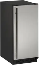
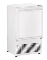
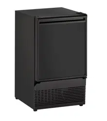
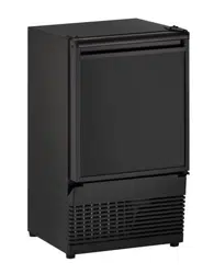
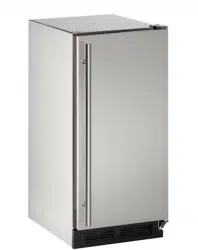
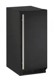
User Manual U-Line UCLR1215S40B 1000 Series Ice Maker
INSTALLATION & INTEGRATION
Environmental Requirements
This model is intended for indoor/interior applications only and is not to be used in installations that are open/ exposed to natural elements.
This unit is designed to operate between 50°F (10°C) and 100° F (38°C). Higher ambient temperatures may reduce the unit’s ability to reach low temperatures and/or reduce ice production on applicable models.
For best performance, keep the unit out of direct sunlight and away from heat generating equipment.
In climates where high humidity and dew points are present, condensation may appear on outside surfaces. This is considered normal. The condensation will evaporate when the humidity drops.

Damages caused by ambient temperatures of 40°F (4°C) or below are not covered by the
warranty.
Electrical

SHOCK HAZARD — Electrical Grounding
Required. Never attempt to repair or perform maintenance on the unit until the electricity has been disconnected.
Never remove the round grounding prong from the plug and never use a two-prong grounding adapter.
Altering, cutting or removing power cord, removing power plug, or direct wiring can cause serious injury, fire, loss of property and/or life, and will void the warranty.
Never use an extension cord to connect power to the unit.
Always keep your working area dry.
NOTICE
Electrical installation must observe all state and local codes. This unit requires connection to a grounded (three-prong), polarized receptacle that has been placed by a qualified electrician.
The unit requires a grounded and polarized 115 VAC,
Hz, 15A power supply (normal household current). An individual, properly grounded branch circuit or circuit breaker is recommended. A GFCI (ground fault circuit interrupter) is usually not required for fixed location appliances and is not recommended for your unit because it could be prone to nuisance tripping. However, be sure to consult your local codes.
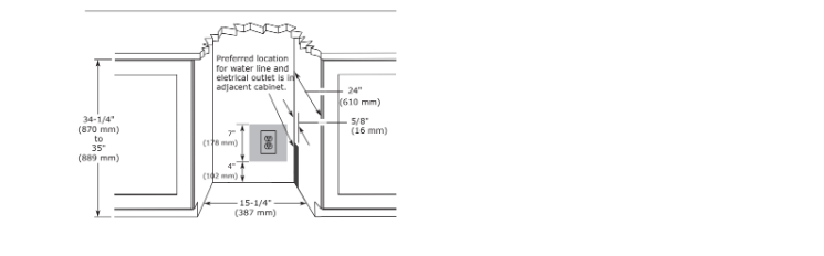
See CUTOUT DIMENSIONS for recommended receptacle location.
Cutout Dimensions
PREPARE SITE
Your U-Line product has been designed for either free- standing or built-in installation. When built-in, your unit does not require additional air space for top, sides, or rear. However, the front grille must NOT be obstructed, and clearance is required for an electrical connection in the rear.
Unit can NOT be installed behind a closed cabinet door.
If you would like to align the face of the unit with other adjacent cabinet doors, you may need to alter the wall just behind the drain connection on the unit to accommodate the drain.
CUTOUT DIMENSIONS
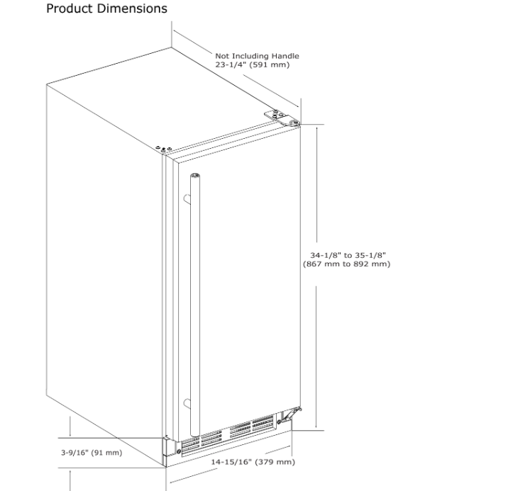
Product Dimensions
Side-by-Side Installation
Two units may be installed side-by-side.
Cutout width for a side-by-side installation is the cutout dimension of a single unit times two.
No trim kit is required. However, 1/4" (6 mm) of space needs to be maintained between the units to ensure unobstructed door swing.
Units must operate from separate, properly grounded electrical receptacles placed according to each unit’s electrical specifications requirements.
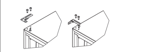
Side-by-Side Installation with Bracket
1. Slide both units out so screws on top of units are easily accessible.
2. Remove screws as shown below.
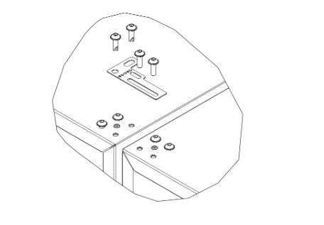
3. Place bracket over holes and attach to unit with two screws removed in step 2 using a T-25 Torx driver. Tighten screws fully.
4. Gently push units into position. Be careful not to entangle the electrical cord or water line, if applicable.
5. Re-check the leveling, from front to back and side to side. Make any necessary adjustments. The unit’s top surface should be approximately 1/8" (3 mm) below the countertop.
Water Hookup
PREPARE PLUMBING
Please use the braided stainless steel water supply line which comes attached. The water line is fitted with a standard 1/4" (6.35 mm) compression fitting.
Prior to installation, determine if this product contains a gravity style drain or factory installed drain pump. Products without a drain pump may only use a gravity style drain. Failure to connect water supply or drain line connections properly may result in water leakage, personal injury, and/or property damage. Disconnect power and turn off water to the unit before attempting to alter these connections. These connections are the responsibility of the owner and must be connected per local plumbing code. If you are uncertain of how to safely and properly install this product, contact a licensed plumber.
Water Supply Connection
Review, obey, and understand the local plumbing codes before you install your unit.
Connect to the cold water supply. The water pressure should be between 20 and 120 psi (138 and 827 kPa). The water line MUST have a shut- off valve on the supply line.
Do not use any plastic water supply line. The line is under pressure at all times. Plastic may crack or rupture with age and cause damage to your home.
Do not use tape or joint compound when attaching a braided flexible water supply line that includes a rubber gasket. The gasket provides an adequate seal – other materials could cause blockage of the valve.
Failure to follow recommendations and instructions may result in damage and/or harm, flooding or void the product warranty.
Turn off water supply and disconnect electrical supply to unit prior to installation.
1. Turn off water supply and disconnect electrical supply to unit prior to installation.
2. Locate the desired cold water supply location.
3. Locate braided stainless steel water supply line and connect to your cold water supply. The water line should be looped into coils. This will allow the unit to be removed for cleaning and servicing. However, make certain that the tubing is not pinched or damaged during installation.
4. Turn on water and check for leaks.
5. Route water supply line in cable clamp and secure with screw.
Drain
Model numbers including “-00” or “-07” do not include a factory installed drain pump.
Model numbers including “-40” or “-47” include a factory installed drain pump.
DRAIN CONNECTION

If your U-Line unit did not come with a factory installed drain pump you must use a gravity style drain connection. For assistance in determining if your unit has a pump please contact U-Line. The floor drain must be large enough to accommodate drainage from all attached drains. Follow these guidelines when installing drain lines to prevent water from flowing back into the ice maker storage bin and/ or potentially flowing onto the floor, which may result in personal injury or property damage.
NOTICE
Drain can NOT be located directly below the unit.
Unit has a solid base that will not allow the unit to drain below itself.
There is a possibility that hose connections may have loosened during shipment.
Verify all connections and fittings are free from leaks.
GRAVITY DRAIN
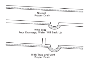
A gravity drain may be used if:
Drain line has at least a 1" drop per 48" (approximately cm drop per 100 cm) of run.
Drain line does not create traps and is vented per local code.
- Cut the pre-installed drain tube to length.
- Connect to your local plumbing per the local code.
- If necessary, insulate drain line to prevent condensation.
Failure to connect water supply or drain line connections properly can result in personal injury and property damage. Gravity drain connections must be routed downward from the rest of the unit at the rate of 1/4" per foot (1 cm per 50 cm).
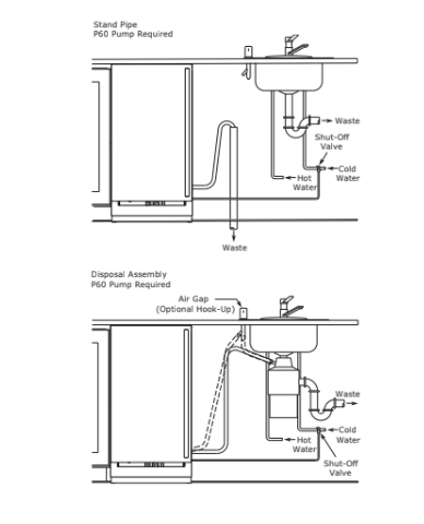
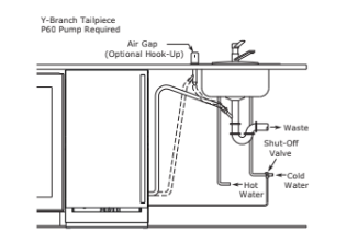
FACTORY INSTALLED DRAIN PUMP
If your drain line will run up to a stand pipe, disposal or spigot assembly, or does not otherwise meet the requirements for a gravity drain, you may have ordered a pre-installed U-Line P60 drain pump.
If you need to install a P60 drain pump into your unit, see DRAIN PUMP section in the User Manual.
See below for typical installations requiring a drain pump.
NOTICE
The maximum lift for the P60 drain pump is feet. This must be done as close to the rear of the unit as possible.
Drain Pump
NOTICE
PLEASE READ this instruction completely before attempting to install or operate the unit.
Improper hook-up can result in substantial property damage! If you are unsure of your ability to safely connect the drain pump to the unit, consult a licensed plumber for assistance.
Use these instructions to install the U-Line P60- drain pump in the U-Line Clear Ice Machine unit). The drain pump should be installed before installing the unit.
- The U-Line P60-00 drain pump is designed to be used exclusively on the U-Line Clear Ice Machine and is UL recognized only for use on the U-Line Clear Ice Machine.
- U-Line Corporation assumes no warranties or responsibility, whether express or implied, if the P60-00 drain pump is used on another ice machine or product for which it is not UL recognized or listed.
- Modification of the P60-00 drain pump will void all warranties.
NOTICE
Keep your proof of purchase for warranty purposes.
Anti-Tip Bracket
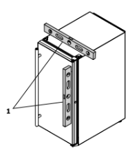
1. Slide unit out so screws on top of unit are easily accessible.
2. Remove the two screws from the opposite side of the hinge assembly using a T-25 Torx driver (see below).
NOTE: 1224 models shown with four screw. 1215 models only have three screws, but same screws are used in both applications.
3. Place bracket (part #14154) over holes and attach to unit with two screws removed in step 2 using a T-25 Torx driver. Tighten screws fully.
4. Gently push unit into position. Be careful not to entangle the electrical cord or water line, if applicable.
5. Check to be sure the unit is level from front to back and side to side. Make any necessary adjustments. The unit’s top surface should be approximately 1/8" mm) below the countertop.
6. Secure bracket into adjoining surface.
LEVELING INFORMATION
1. Use a level to confirm the unit is level. Level should be placed along top edge and side edge as shown.
2. If the unit is not level, adjust the legs on the corners of the unit as necessary.

3. Confirm the unit is level after each adjustment and repeat the previous steps until the unit is level.
INSTALLATION TIP
If the room floor is higher than the floor in the cutout opening, adjust the rear legs to achieve a total unit rear height of 1/8" (3 mm) less than the opening’s rear height. Shorten the unit height in the front by adjusting the front legs. This allows the unit to be gently tipped into the opening. Readjust the front legs to level the unit after it is correctly positioned in the opening.
INSTALLATION
- Plug in the power/electrical cord.
- Gently push the unit into position. Be careful not to entangle the cord or water and drain lines.
- Re-check the leveling, from front to back and side to side. Make any necessary adjustments. The unit’s top surface should be approximately 1/8" (3 mm) below the countertop.
- Install the anti-tip bracket.
- Remove interior packing material and wipe out the inside of the unit with a clean, water-dampened cloth.
Door Swing
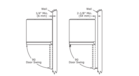
Units have a zero clearance for the door to open 90°, when installed adjacent to cabinets.
Stainless Steel and black and white models require 2-1/8" mm) door clearance to accommodate the handle if installed next to a wall.
Integrated models require 1/4" (6 mm) clearance if installed next to a wall. Allow for additional space for any knobs or pulls installed on the integrated panel/frame.
OPERATING INSTRUCTIONS
Ice
ICE CUBE THICKNESS ADJUSTMENT
Interval - As Required
NOTICE
Ice thickness adjustment should only be made one increment at a time. Allow ice maker production to stabilize for 24 hours before rechecking ice thickness.
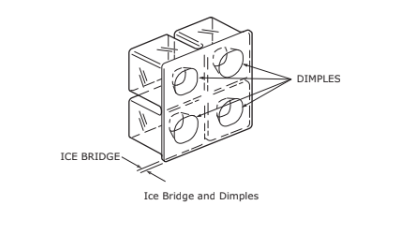
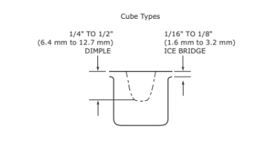
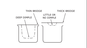
The ice cube thickness is factory set for best overall performance. The factory setting is designed to maintain an ice bridge of approximately 1/16" to 1/8" (1.6 mm to mm) under normal conditions, resulting in a dimple of approximately 1/4" to 1/2" (6.4 mm to 12.7 mm) in depth. A fuller cube with less of a dimple results in a thicker ice bridge. As the ice bridge becomes thicker, the tendency for the cubes to stay together as a slab increases. A bridge thicker than 1/8" (3.2 mm) may cause cubes to overfill the ice bucket.
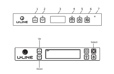
Ice thickness adjustments are made using the control panel as follows:
1. To enter the thickness adjustment mode:
- Press and hold for 5 seconds.
- The display will switch to “0” to confirm the thickness adjustment mode has been selected.
The factory setting is “0,” and the total range of adjustment is -5 to +5 (ideal range is -1 to +1). Use to raise the setting and thicken the ice bridge, or to lower the setting to thin the ice bridge.
Ice cubes in any given batch will vary, so it is necessary to choose cubes from the sample area for comparison when making adjustments.
Sabbath Mode
U-Line Clear Ice Machine models are Star-K certified and can be used during the Sabbath. View a full list of Star-K certified U-Line units at www.star-k.org.
To prepare the unit for the Sabbath:
- Press and hold the until the unit turns off.
- No new ice will form when the unit is off, but previously made ice will still be accessible/present for over 24 hours. Pump equipped models will continue to remove water as needed even if the unit is off.
Sabbath Mode remains active until is pressed again and the unit turns on.
MAINTENANCE
Cleaning
EXTERIOR CLEANING
Vinyl Clad (Black or White) Models
Clean surfaces with a mild detergent and warm water solution. Do not use solvent-based or abrasive cleaners.
Use a soft sponge and rinse with clean water. Wipe with a soft, clean towel to prevent water spotting.
Clean any glass surfaces with a non-chlorine glass cleaner.
Stainless Models
Stainless door panels, handles and frames can discolor when exposed to chlorine gas, pool chemicals, saltwater or cleaners with bleach.
Keep your stainless unit looking new by cleaning with a good quality all-in-one stainless steel cleaner and polish monthly. For best results use Claire® Stainless Steel Polish and Cleaner. Comparable products are acceptable.
Frequent cleaning will remove surface contamination that could lead to rust. Some installations may require cleaning weekly.
Do not clean with steel wool pads.
Do not use stainless steel cleaners or polishes on any glass surfaces.
Clean any glass surfaces with a non-chlorine glass cleaner.
Do not use cleaners not specifically intended for stainless steel on stainless surfaces (this includes glass, tile and counter cleaners).
If any surface discoloring or rusting appears, clean it quickly with Bon-Ami® or Barkeepers Friend Cleanser® and a nonabrasive cloth. Always clean with the grain. Always finish with Claire® Stainless Steel Polish and Cleaner or comparable product to prevent further problems.
Using abrasive pads such as ScotchBriteTM will cause the graining in the stainless steel to become blurred.
Rust not cleaned up promptly can penetrate the surface of the stainless steel and complete removal of the rust may not be possible.
Integrated Models
To clean integrated panels, use household cleaner per the cabinet manufacturer’s recommendations.
INTERIOR CLEANING
Disconnect power to the unit.
Clean the interior and all removed components using a mild nonabrasive detergent and warm water solution applied with a soft sponge or non-abrasive cloth.
Rinse the interior using a soft sponge and clean water.
Do not use any solvent-based or abrasive cleaners. These types of cleaners may transfer taste and/or odor to the interior products and damage or discolor the interior.
CLEAR ICE MACHINE CLEANING CYCLE
Your U-Line clear ice machine has an automatic clean alert function. Cleaning cycles should be run as notified. Otherwise, to maintain operational efficiency the unit should be cleaned every three months. Depending on water conditions, more frequent cleaning may be necessary. If the ice machine requires more frequent cleaning, consult a plumber to test the water quality and recommend appropriate treatment.

Wear rubber gloves and safety goggles and/or face shield when handling Ice Machine Cleaner.
NOTICE
Use only U-Line Ice Machine Cleaner (Part No. available from your dealer or direct from your local parts distributor. To locate a parts distributor near you, visit www.u-line.com. It is a violation of federal law to use this solution in a manner inconsistent with its labeling. Use of any other cleaner can ruin the finish of the evaporator and will void the warranty. Read and understand all labels printed on the package before use.
U-Line Ice Machine Cleaner is used to remove lime scale and other mineral deposits. Refer to the following steps to initiate the self-cleaning
Never use anything to force ice from the evaporator. Damage may result.
1. Turn the ice machine off and allow any ice to melt off of the evaporator.
2. Remove all ice from the storage bin.
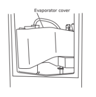
3. Remove evaporator cover.
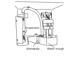
4. Remove the standpipe by lifting it up while using a slight back and forth motion to loosen it from the drain hole. The water in the reservoir will flow down the drain.
5. Re-install the standpipe into the water trough.
6. Clean the Interior Bin as follows:
- Dilute one packet of CLR cleaner into two quarts of water.
- Using a sponge or cloth, clean interior of ice bin, tubing and door. This cleaner will remove all mineral deposits and other contaminants from the surfaces.
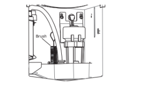
- Using a bottle brush, clean out the trough drain tube and pump tubing where needed.
7. Turn unit on by pressing .
8. Place the unit into CLEAN mode by holding for seconds.
9. When water begins flowing over the evaporator approximately 3 minutes), pour 1 packet of CLR cleaner into the water trough. The cleaning process will last approximately 45 minutes.
10. Dilute 1 tablespoon bleach in 1 gallon of warm water. Apply this solution to the entire inside of the storage area. Then rinse thoroughly with water.
The unit will resume operation approximately 15 minutes after the automated cleaning process is completed. The water fill valve will energize, fill the water reservoir, and shut-off after three minutes. The compressor begins to operate and water flows over the evaporator assembly (ice mold). Initially, the water flow may not be uniform, causing uneven sized cubes or water to spill into the ice storage bin. This is a normal situation that will correct itself within the first 24 hours of operation.
NOTICE
Discard all ice produced in the first harvest.
Should power to the unit be interrupted during the self-clean cycle, it will be necessary to repeat the complete cleaning cycle after power is restored.
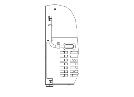
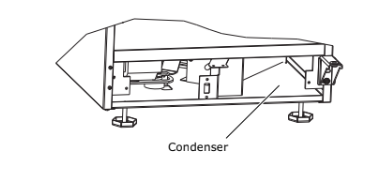
Cleaning Condenser
INTERVAL - EVERY SIX MONTHS
To maintain operational efficiency, keep the front grille free of dust and lint, and clean the condenser when necessary. Depending on environmental conditions, more or less frequent cleaning may be necessary.

Disconnect electric power to the unit before cleaning the condenser.
NOTICE
DO NOT use any type of cleaner on the condenser unit. Condenser may be cleaned using a vacuum, soft brush or compressed air.
- Remove the grille. (See GRILLE-PLINTH INSTALLATION).
- Clean the condenser coil using a soft brush or vacuum cleaner.
- Install the grille.
Extended Non-Use
VACATION/HOLIDAY, PROLONGED SHUTDOWN
The following steps are recommended for periods of extended non-use:
- Remove all consumable content from the unit.
- Disconnect the power cord from its outlet/socket and leave it disconnected until the unit is returned to service.
- Turn off the water supply.
- If ice is on the evaporator, allow ice to thaw naturally.
- Clean and dry the interior of the cabinet. Ensure all water has been removed from the unit.
- Disconnect the water and drain line (if applicable) making sure all water is removed from the lines.
- The door must remain open to prevent formation of mold and mildew. Open door a minimum of 2" mm) to provide the necessary ventilation.
WINTERIZATION
If the unit will be exposed to temperatures of 40°F (5°C) or less, the steps above must be followed. In addition, P60 drain pumps in clear ice machines must be drained according to the following procedure:
- Remove the drain pump from the ice machine.
- Drain the water in the pump’s reservoir by turning the pump upside down and allowing the water to drain through the pump’s inlet and vent tube fittings.
- After water is drained, reinstall the drain pump and reattach all connections.
SERVICE
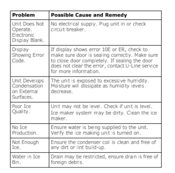
Troubleshooting
BEFORE CALLING FOR SERVICE
If you think your U-Line product is malfunctioning, read the CONTROL OPERATION section to clearly understand the function of the control.
If the problem persists, read the NORMAL OPERATINGSOUNDS and TROUBLESHOOTING GUIDE sections below to help you quickly identify common problems and possible causes and remedies. Most often, this will resolve the problem without the need to call for service.
IF SERVICE IS REQUIRED
If you do not understand a troubleshooting remedy, or your product needs service, contact U-Line Corporation directly at +1.800.779.2547.
When you call, you will need your product Model and Serial Numbers. This information appears on the Model and Serial number plate located on the upper right or rear wall of the interior of your product.
NORMAL OPERATING SOUNDS
All models incorporate rigid foam insulated cabinets to provide high thermal efficiency and maximum sound reduction for its internal working components. Despite this technology, your model may make sounds that are unfamiliar.
Normal operating sounds may be more noticeable because of the unit’s environment. Hard surfaces such as cabinets, wood, vinyl or tiled floors and paneled walls have a tendency to reflect normal appliance operating noises.
Listed below are common refrigeration components with a brief description of the normal operating sounds they make. NOTE: Your product may not contain all the components listed.
- Compressor: The compressor makes a hum or pulsing sound that may be heard when it operates.
- Evaporator: Refrigerant flowing through an evaporator may sound like boiling liquid.
- Condenser Fan: Air moving through a condenser may be heard.
- Running Water: As your unit continues to produce ice you will hear water flowing into the collection chambers and running over the evaporator.
TROUBLESHOOTING GUIDE

ELECTROCUTION HAZARD. Never attempt to repair or perform maintenance on the unit before disconnecting the main electrical power.
Troubleshooting - What to check when problems occur:
U-Line Corporation | Limited Warranty
- U-Line Corporation (“U-Line”) warrants each U-Line product to be free from defects in materials and workmanship for a period of one year (two years on Modular 3000 Series) from the date of installation. U-Line further warrants the sealed system (consisting of the compressor, condenser, evaporator, hot gas bypass valve, dryer, and connecting tube) in each U-Line product to be free from defects in materials and workmanship for a period of five years from the date of installation.
- During the initial one year warranty period (two years on Modular 3000 Series) for all U-Line products U-Line shall: (1) repair any product or replace any part of a product; and (2) for all Marine, RV and Domestic U-Line products sold and serviced in the United States including Alaska and Hawaii) and Canada, U-Line shall be responsible for the labor costs performed by a U-Line authorized service company, incurred in connection with the replacement of any defective part.During years two through five of the warranty period for the sealed system, U-Line shall: (1) at U-Line’s option repair or replace any part of the sealed system; and (2) for all Marine, RV and Domestic U-Line products sold and serviced in the United States including Alaska and Hawaii) and Canada, U-Line shall be responsible for the labor costs incurred in connection with the replacement of any defective part of the sealed system. All other charges, including transportation charges for replacements under this warranty and labor costs not specifically covered by this warranty, shall be the responsibility of the purchaser. This warranty extends only to the original purchaser of the U-Line product.
- The warranty listed above does not apply to floor display models. The warranty for these models shall be one year from the date of installation. This one-year warranty does not apply to cosmetic damages; proof of purchase may be required.
- The following conditions are excluded from this limited warranty: use of cleaners other than the recommended stainless steel cleaners and U-Line Clear Ice Maker cleaner; installation charges; damages caused by disasters or acts of God, such as fire, floods, wind and lightning; damages incurred or resulting from shipping, improper installation, unauthorized modification, or misuse/abuse of the product; customer education calls; food loss and spoilage; door and water level adjustments (except during the first 30 days from the date of installation); defrosting the product; adjusting the controls; door reversal; and cleaning the condenser.
- U-Line products are designed to operate in ambient temperatures between 50°F and 100°F unless otherwise noted in the product manual. Exposure to temperatures outside this range may cause degradation of performance and issues such as lower ice production or spoiled contents are not covered under the terms of this warranty as a result of that exposure. U-Line product may not be subjected to temperatures below 40°F without following the winterization and vacation shutdown procedures in your product manual.
- U-Line’s Outdoor Limited Warranty, set forth in this Paragraph 6, shall apply to U-Line models deemed suitable for outdoor use by Underwriters Laboratory UL”) as noted in the U-Line Product Catalog, U-Line’s website and/or on the serial tag located inside the product. Outdoor product may come into contact with rain by virtue of outdoor use. Exposure to other sources of water shall also cause this warranty to be void, including flooding of the area in proximity of the unit greater than 1/8" deep in water, hurricanes, splashing of pool water, or directing a spray from a hose or similar device into and around the unit.
- If a product defect is discovered during the applicable warranty period, you must promptly notify U-Line at 1- or the dealer from whom you purchased the product. In no event shall such notification be received later than 30 days after the expiration of the applicable warranty period. U-Line may require that defective parts be returned, at your expense, to U-Line’s factory in Milwaukee, Wisconsin, for inspection.Any action by you for breach of warranty must be commenced within one year after the applicable warranty period.
- THIS LIMITED WARRANTY IS IN LIEU OF ANY AND ALL OTHER WARRANTIES, EXPRESS OR IMPLIED,INCLUDING ANY IMPLIED WARRANTY OF MERCHANTABILITY OR IMPLIED WARRANTY OF FITNESS FOR A PARTICULAR PURPOSE, ALL OF WHICH ARE DISCLAIMED. U-Line’s sole liability and your exclusive remedy under this warranty are set forth in the paragraphs above. U-Line shall have no liability whatsoever for any incidental, consequential or special damages arising from the sale, use or installation of the product or from any other cause whatsoever whether based on warranty (express or implied) or otherwise based on contract, tort or any other theory of liability.
- Some states do not allow limitations on how long an implied warranty lasts or the exclusion or limitation of incidental or consequential damages, so the above limitations may not apply to you. This warranty gives you specific legal rights, and you may also have other rights which vary from state to state.
- Copyright © 2014 U-Line Corporation. All Rights Reserved. | Publication Number 30379 | 03/2016 Rev. I