USER GUIDE & SERVICE MANUAL
SAFETY • INSTALLATION & INTEGRATION • OPERATING INSTRUCTIONS • MAINTENANCE • SERVICE
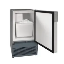
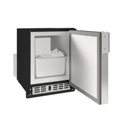
1000 Series •
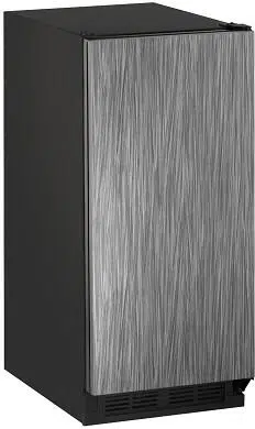
CLR1215 •
15" Clear Ice Maker
RIGHT PRODUCT. RIGHT PLACE. RIGHT TEMPERATURE. SINCE 1962.
USER GUIDE & SERVICE MANUAL
u-line.com
Table of Contents
Intro
Safety
Safety and Warning
Disposal And Recycling
Installation
Environmental Requirements
Electrical
Cutout Dimensions
Product Dimensions
Side by Side Installation
Water Hookup
Drain
Anti-Tip Bracket
General Installation
Grille / Plinth Installation
Door Swing
Door Adjust
Maintenance
Cleaning
Cleaning Condenser
Extended Non-Use
Operating Instructions
First Use
Control Operation
Ice
Sabbath Mode
Airflow and Product Loading
Service
Troubleshooting
Wire Diagram
Product Liability
Warranty Claims
Parts
Ordering Replacement Parts
System Diagnosis Guide
Compressor Specifications
Troubleshooting Extended
Control Operation - Service
Thermistor
Defrost
Warranty
USER GUIDE
Introduction 1
u-line.com
WELCOME TO U-LINE
Congratulations on your U-Line purchase. Your product comes from a company with over five decades of premium modular
ice making, refrigeration, and wine preservation experience. U-Line continues to be the American leader, delivering versatility
and flexibility for multiple applications including residential, light commercial, outdoor and marine use. U-Line’s complete
product collection includes Wine Captain
®
Models, Beverage Centers, Clear Ice Machines, Crescent Ice Makers, Glass & Solid
Door Refrigerators, Drawer Models, Freezers, Combo
®
Models, and more.
U-Line has captivated those with an appreciation for the finer things with exceptional functionality, style, inspired innovations
and attention to even the smallest details. We are known and respected for our unwavering dedication to product design,
quality and selection. U-Line is headquartered in Milwaukee, Wisconsin and has shipped product to five continents for over
two decades and is proud to have the opportunity to ship to you.
PRODUCT INFORMATION
Looking for additional information on your product? User Guides, Spec Sheets, CAD Drawings, Compliance Documentation,
and Product Warranty information are all available for reference and download at u-line.com.
PROPERTY DAMAGE / INJURY CONCERNS
In the unlikely event property damage or personal injury is suspected related to a U-Line product, please take the following
steps:
1. U-Line Customer Care must be contacted immediately at +1.800.779.2547.
2. Service or repairs performed on the unit without prior written approval from U-Line is not permitted. If the unit has been
altered or repaired in the field without prior written approval from U-Line, claims will not be eligible.
GENERAL INQUIRIES
U-Line Corporation
8900 N. 55th Street
Milwaukee, Wisconsin 53223 USA
Monday - Friday 8:00 am to 4:30 pm CST
T: +1.414.354.0300
F: +1.414.354.7905
Email: sales@u-line.com
u-line.com
SERVICE & PARTS ASSISTANCE
Monday - Friday 8:00 am to 4:30 pm CST
T: +1.800.779.2547
F: +1.414.354.5696
Service Email: onlineservice@u-line.com
Parts Email: onlineparts@u-line.com
CONNECT WITH US
Designed, engineered and assembled in WI, USA
3
USER GUIDE
Safety and Warning 1
u-line.com
SAFETY • INSTALLATION & INTEGRATION • OPERATING INSTRUCTIONS • MAINTENANCE • SERVICE
Safety and Warning
NOTICE
Please read all instructions before installing,
operating, or servicing the appliance.
Use this appliance for its intended purpose only and follow
these general precautions with those listed throughout this
guide:
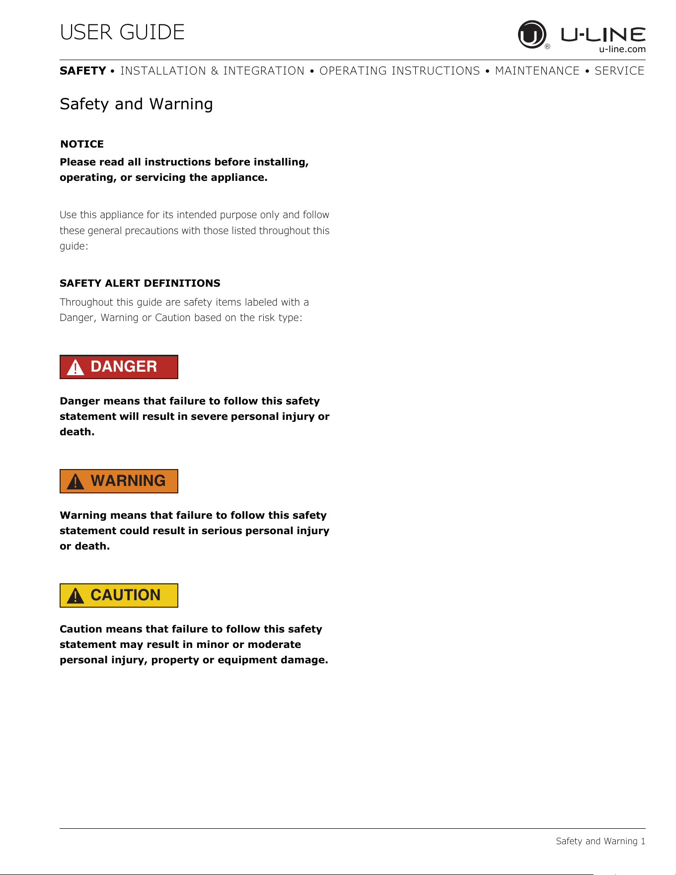
SAFETY ALERT DEFINITIONS
Throughout this guide are safety items labeled with a
Danger, Warning or Caution based on the risk type:
DANGER
!
Danger means that failure to follow this safety
statement will result in severe personal injury or
death.
WARNING
!
Warning means that failure to follow this safety
statement could result in serious personal injury
or death.
CAUTION
!
Caution means that failure to follow this safety
statement may result in minor or moderate
personal injury, property or equipment damage.
4
USER GUIDE
Disposal and Recycling 1
u-line.com
SAFETY • INSTALLATION & INTEGRATION • OPERATING INSTRUCTIONS • MAINTENANCE • SERVICE
Disposal and Recycling
DANGER
!
RISK OF CHILD ENTRAPMENT. Before you throw
away your old refrigerator or freezer, take off
the doors and leave shelves in place so children
may not easily climb inside.
If the unit is being removed from service for disposal,
check and obey all federal, state and local regulations
regarding the disposal and recycling of refrigeration
appliances, and follow these steps completely:
1. Remove all consumable contents from the unit.
2. Unplug the electrical cord from its socket.
3. Remove the door(s)/drawer(s).
5
USER GUIDE
Environmental Requirements 1
u-line.com
SAFETY • INSTALLATION & INTEGRATION • OPERATING INSTRUCTIONS • MAINTENANCE • SERVICE
Environmental Requirements
This model is intended for indoor/interior applications only
and is not to be used in installations that are open/
exposed to natural elements.
This unit is designed to operate between 50°F (10°C) and
100°F (38°C). Higher ambient temperatures may reduce
the unit’s ability to reach low temperatures and/or reduce
ice production on applicable models.
For best performance, keep the unit out of direct sunlight
and away from heat generating equipment.
In climates where high humidity and dew points are
present, condensation may appear on outside surfaces.
This is considered normal. The condensation will
evaporate when the humidity drops.
CAUTION
!
Damages caused by ambient temperatures of
40°F (4°C) or below are not covered by the
warranty.
6
USER GUIDE
Electrical
u-line.com
Electrical
WARNING
!
SHOCK HAZARD — Electrical Grounding
Required. Never attempt to repair or perform
maintenance on the unit until the electricity has
been disconnected.
Never remove the round grounding prong from
the plug and never use a two-prong grounding
adapter.
Altering, cutting or removing power cord,
removing power plug, or direct wiring can cause
serious injury, fire, loss of property and/or life,
and will void the warranty.
Never use an extension cord to connect power to
the unit.
Always keep your working area dry.
NOTICE
Electrical installation must observe all state and
local codes. This unit requires connection to a
grounded (three-prong), polarized receptacle
that has been placed by a qualified electrician.
The unit requires a grounded and polarized 115 VAC,
60 Hz, 15A power supply (normal household current). An
individual, properly grounded branch circuit or circuit
breaker is recommended. A GFCI (ground fault circuit
interrupter) is usually not required for fixed location
appliances and is not recommended for your unit because
it could be prone to nuisance tripping. However, be sure
to consult your local codes.
See CUTOUT DIMENSIONS for recommended receptacle
location.
7
USER GUIDE
Cutout Dimensions 1
u-line.com
SAFETY • INSTALLATION & INTEGRATION • OPERATING INSTRUCTIONS • MAINTENANCE • SERVICE
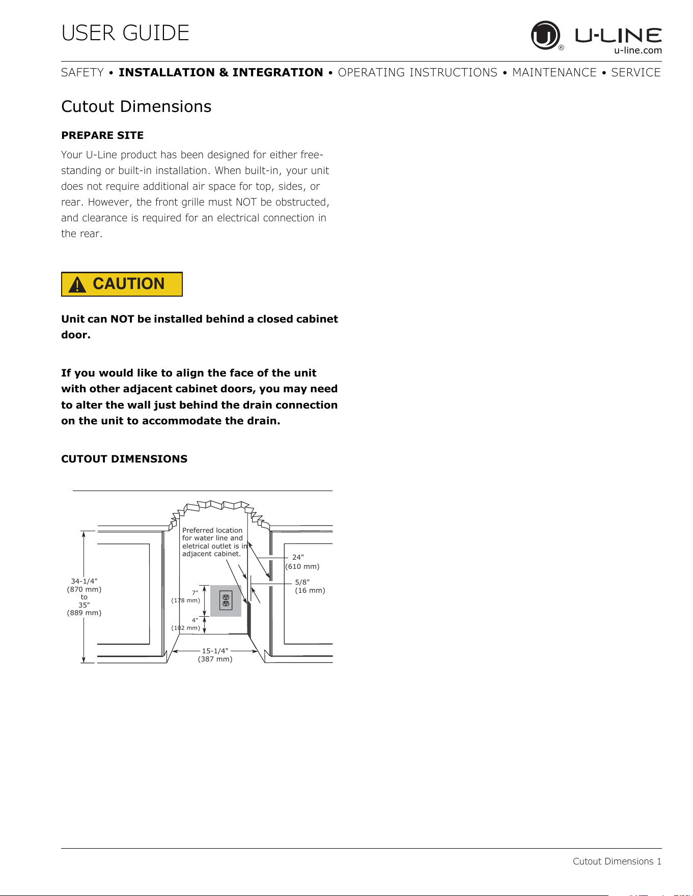
Cutout Dimensions
PREPARE SITE
Your U-Line product has been designed for either free-
standing or built-in installation. When built-in, your unit
does not require additional air space for top, sides, or
rear. However, the front grille must NOT be obstructed,
and clearance is required for an electrical connection in
the rear.
CAUTION
!
Unit can NOT be installed behind a closed cabinet
door.
If you would like to align the face of the unit
with other adjacent cabinet doors, you may need
to alter the wall just behind the drain connection
on the unit to accommodate the drain.
CUTOUT DIMENSIONS
34-1/4"
(870 mm)
to
35"
(889 mm)
15-1/4"
(387 mm)
24"
(610 mm)
4"
(102 mm)
7"
(178 mm)
5/8"
(16 mm)
Preferred location
for water line and
eletrical outlet is in
adjacent cabinet.
8
USER GUIDE
Product Dimensions 1
u-line.com
SAFETY • INSTALLATION & INTEGRATION • OPERATING INSTRUCTIONS • MAINTENANCE • SERVICE
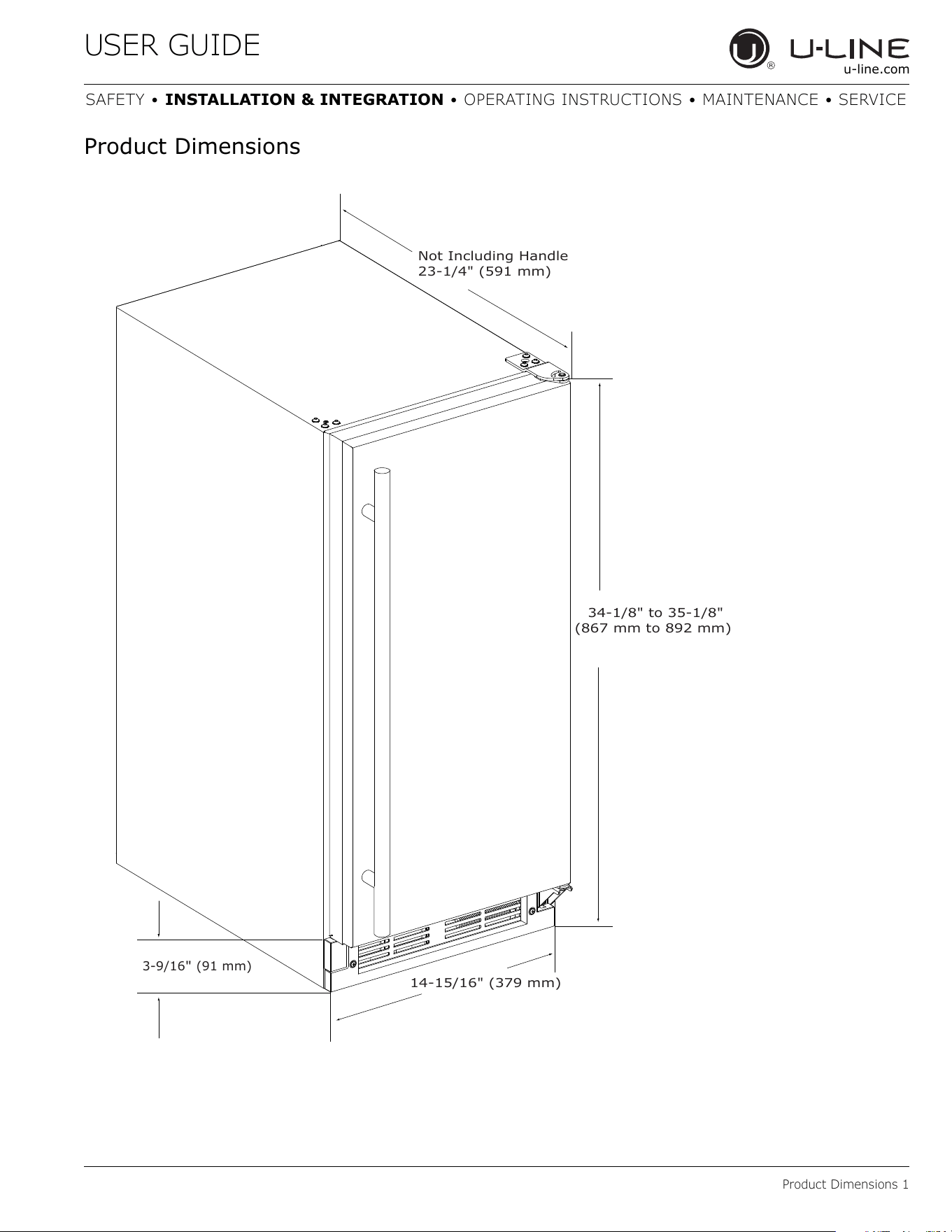
Product Dimensions
34-1/8" to 35-1/8"
(867 mm to 892 mm)
14-15/16" (379 mm)
3-9/16
"
(91 mm)
Not Including Handle
23-1/4" (591 mm)
9
USER GUIDE
Side-by-Side Installation
u-line.com
Side-by-Side Installation
Two units may be installed side-by-side.
Cutout width for a side-by-side installation is the cutout
dimension of a single unit times two.
No trim kit is required. However, 1/4" (6 mm) of space
needs to be maintained between the units to ensure
unobstructed door swing.
Units must operate from separate, properly grounded
electrical receptacles placed according to each unit’s
electrical specifications requirements.
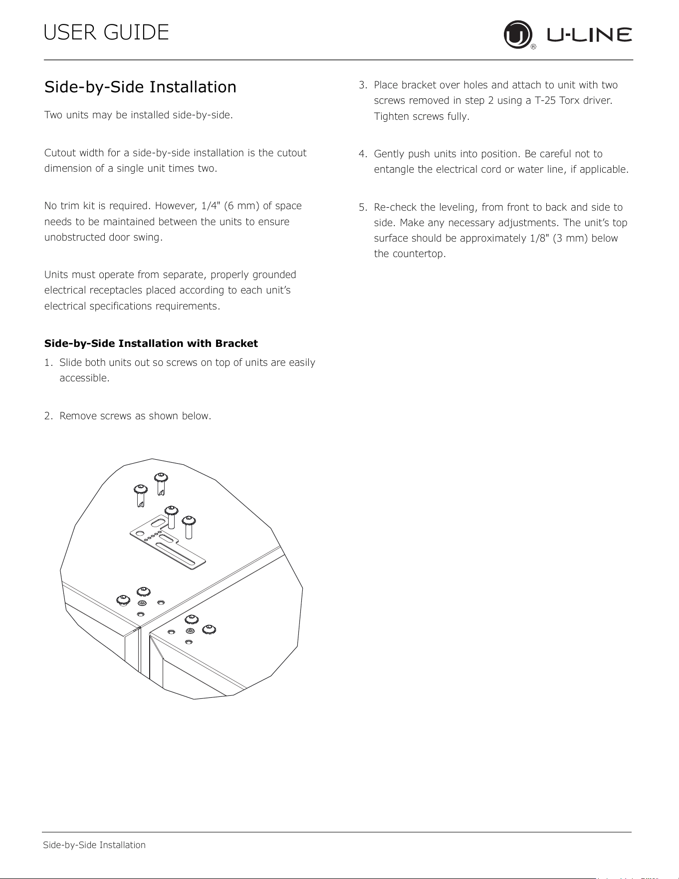
Side-by-Side Installation with Bracket
1. Slide both units out so screws on top of units are easily
accessible.
2. Remove screws as shown below.
3. Place bracket over holes and attach to unit with two
screws removed in step 2 using a T-25 Torx driver.
Tighten screws fully.
4. Gently push units into position. Be careful not to
entangle the electrical cord or water line, if applicable.
5. Re-check the leveling, from front to back and side to
side. Make any necessary adjustments. The unit’s top
surface should be approximately 1/8" (3 mm) below
the countertop.
10
USER GUIDE
Door Swing 1
u-line.com
SAFETY • INSTALLATION & INTEGRATION • OPERATING INSTRUCTIONS • MAINTENANCE • SERVICE
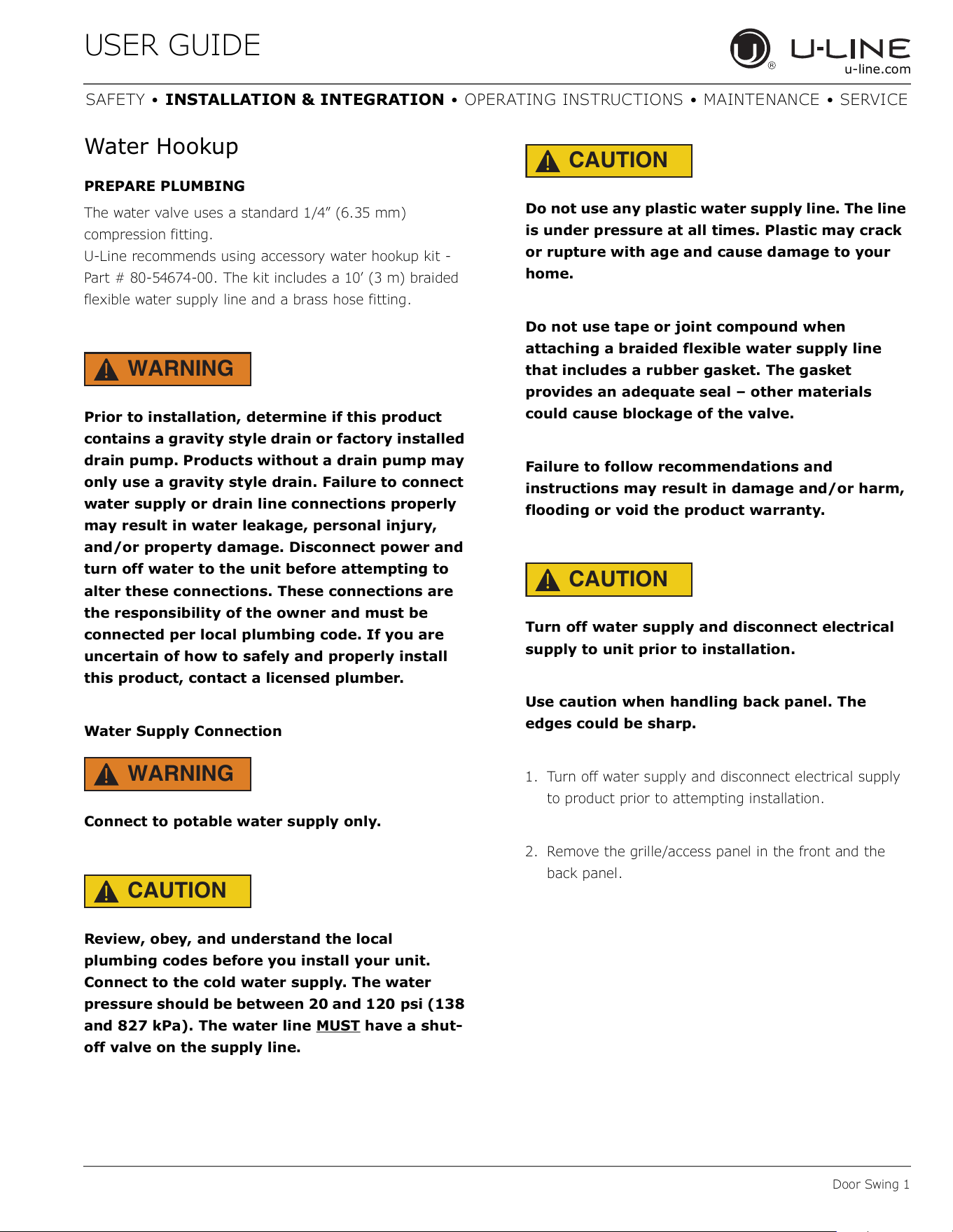
Water Hookup
PREPARE PLUMBING
The water valve uses a standard 1/4” (6.35 mm)
compression fitting.
U-Line recommends using accessory water hookup kit -
Part # 80-54674-00. The kit includes a 10’ (3 m) braided
flexible water supply line and a brass hose fitting.
WARNING
!
Prior to installation, determine if this product
contains a gravity style drain or factory installed
drain pump. Products without a drain pump may
only use a gravity style drain. Failure to connect
water supply or drain line connections properly
may result in water leakage, personal injury,
and/or property damage. Disconnect power and
turn off water to the unit before attempting to
alter these connections. These connections are
the responsibility of the owner and must be
connected per local plumbing code. If you are
uncertain of how to safely and properly install
this product, contact a licensed plumber.
Water Supply Connection
WARNING
!
Connect to potable water supply only.
CAUTION
!
Review, obey, and understand the local
plumbing codes before you install your unit.
Connect to the cold water supply. The water
pressure should be between 20 and 120 psi (138
and 827 kPa). The water line MUST
have a shut-
off valve on the supply line.
CAUTION
!
Do not use any plastic water supply line. The line
is under pressure at all times. Plastic may crack
or rupture with age and cause damage to your
home.
Do not use tape or joint compound when
attaching a braided flexible water supply line
that includes a rubber gasket. The gasket
provides an adequate seal – other materials
could cause blockage of the valve.
Failure to follow recommendations and
instructions may result in damage and/or harm,
flooding or void the product warranty.
CAUTION
!
Turn off water supply and disconnect electrical
supply to unit prior to installation.
Use caution when handling back panel. The
edges could be sharp.
1. Turn off water supply and disconnect electrical supply
to product prior to attempting installation.
2. Remove the grille/access panel in the front and the
back panel.
11
USER GUIDE
Door Swing 2
u-line.com
SAFETY • INSTALLATION & INTEGRATION • OPERATING INSTRUCTIONS • MAINTENANCE • SERVICE
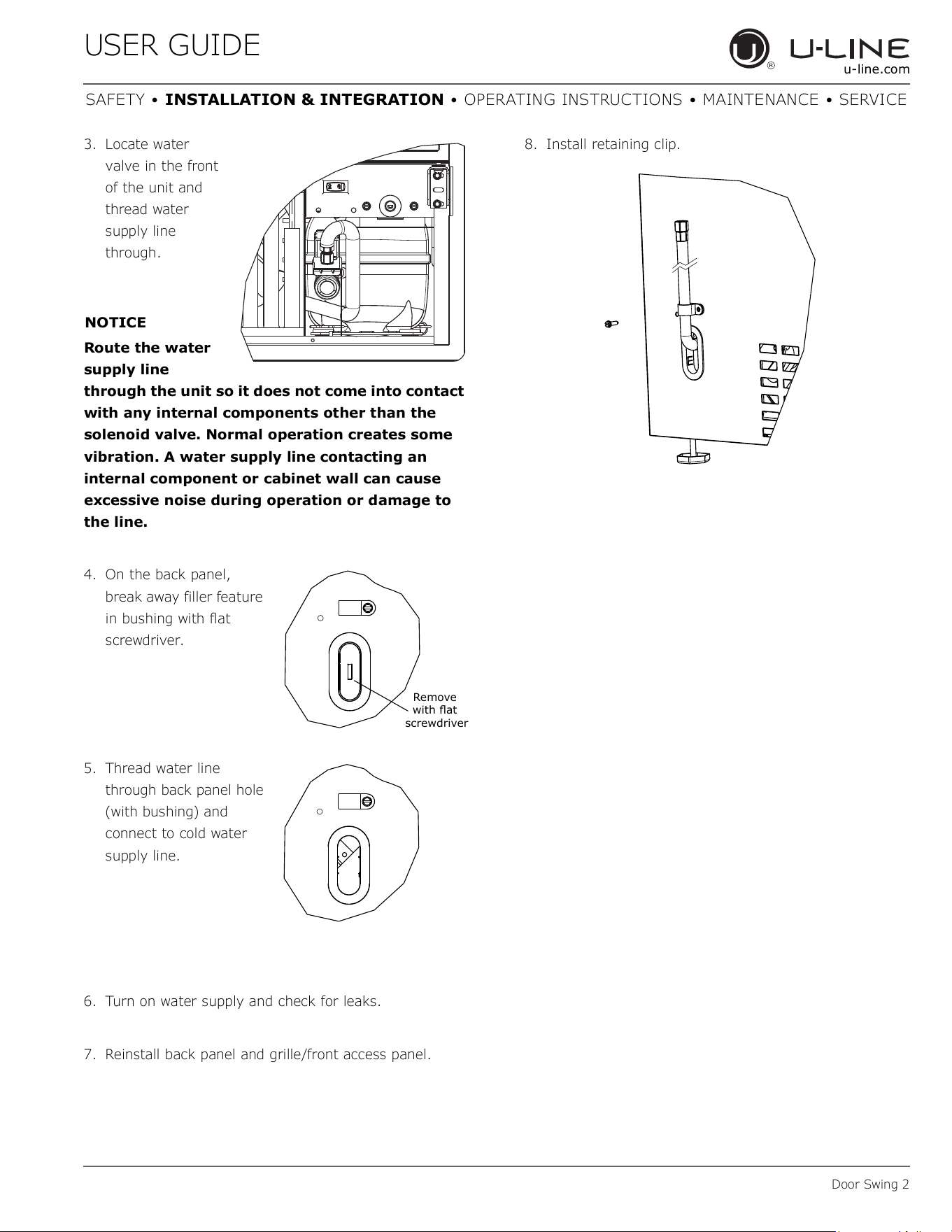
3. Locate water
valve in the front
of the unit and
thread water
supply line
through.
NOTICE
Route the water
supply line
through the unit so it does not come into contact
with any internal components other than the
solenoid valve. Normal operation creates some
vibration. A water supply line contacting an
internal component or cabinet wall can cause
excessive noise during operation or damage to
the line.
4. On the back panel,
break away filler feature
in bushing with flat
screwdriver.
5. Thread water line
through back panel hole
(with bushing) and
connect to cold water
supply line.
6. Turn on water supply and check for leaks.
7. Reinstall back panel and grille/front access panel.
8. Install retaining clip.
Remove
ZLWKɠDW
screwdrive
r
12
USER GUIDE
Drain 1
u-line.com
SAFETY • INSTALLATION & INTEGRATION • OPERATING INSTRUCTIONS • MAINTENANCE • SERVICE
Drain
Model numbers including “-00” or “-07” do not include a
factory installed drain pump.
Model numbers including “-40” or “-47” include a factory
installed drain pump.
DRAIN CONNECTION
CAUTION
!
If your U-Line unit did not come with a factory
installed drain pump you must use a gravity
style drain connection. For assistance in
determining if your unit has a pump please
contact U-Line. The floor drain must be large
enough to accommodate drainage from all
attached drains. Follow these guidelines when
installing drain lines to prevent water from
flowing back into the ice maker storage bin and/
or potentially flowing onto the floor, which may
result in personal injury or property damage.
NOTICE
Drain can NOT be located directly below the unit.
Unit has a solid base that will not allow the unit
to drain below itself.
There is a possibility that hose connections may
have loosened during shipment.
Verify all connections and fittings are free from
leaks.
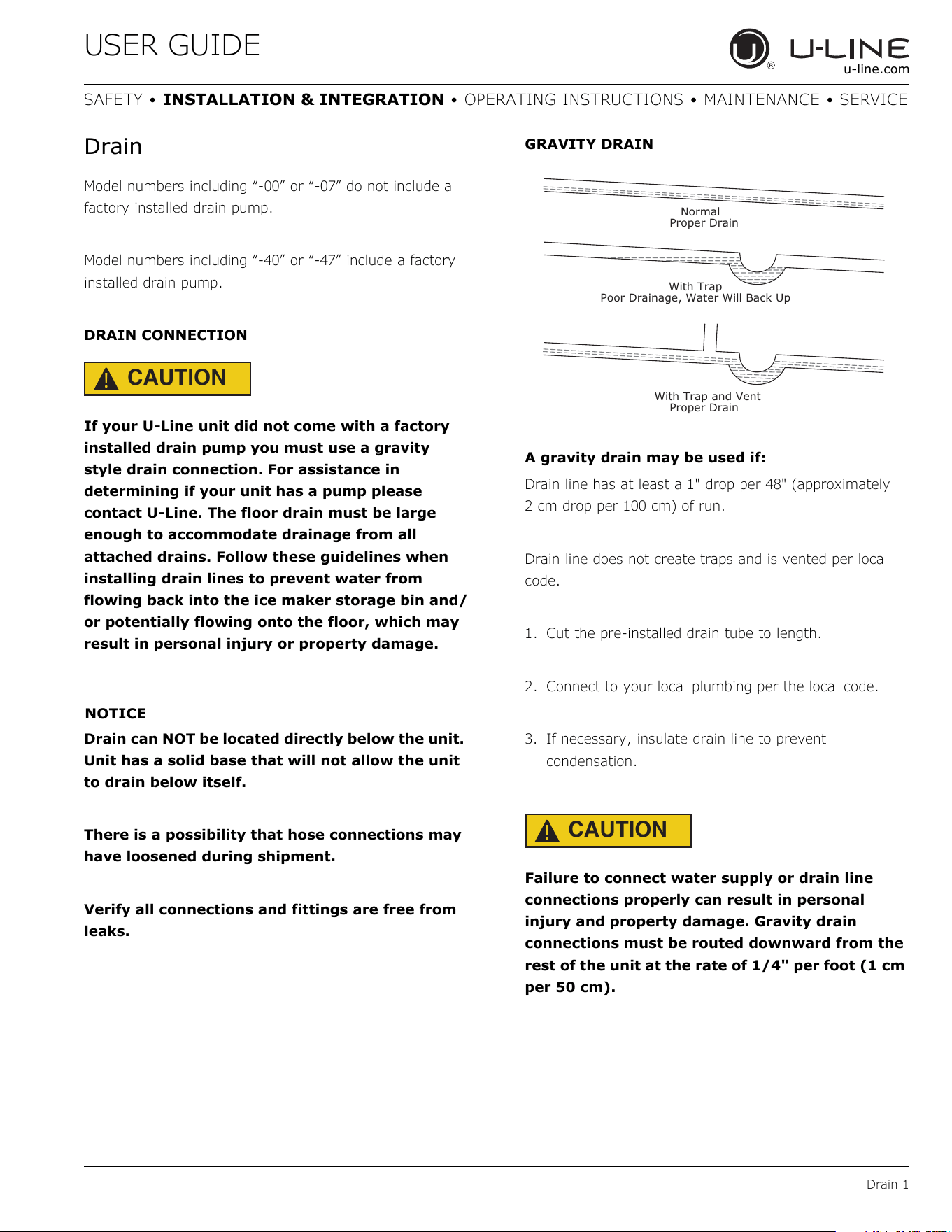
GRAVITY DRAIN
A gravity drain may be used if:
Drain line has at least a 1" drop per 48" (approximately
2 cm drop per 100 cm) of run.
Drain line does not create traps and is vented per local
code.
1. Cut the pre-installed drain tube to length.
2. Connect to your local plumbing per the local code.
3. If necessary, insulate drain line to prevent
condensation.
CAUTION
!
Failure to connect water supply or drain line
connections properly can result in personal
injury and property damage. Gravity drain
connections must be routed downward from the
rest of the unit at the rate of 1/4" per foot (1 cm
per 50 cm).
Normal
Proper Drain
With Trap
Poor Drainage, Water Will Back Up
With Trap and Vent
Proper Drain
13
USER GUIDE
Drain 2
u-line.com
SAFETY • INSTALLATION & INTEGRATION • OPERATING INSTRUCTIONS • MAINTENANCE • SERVICE
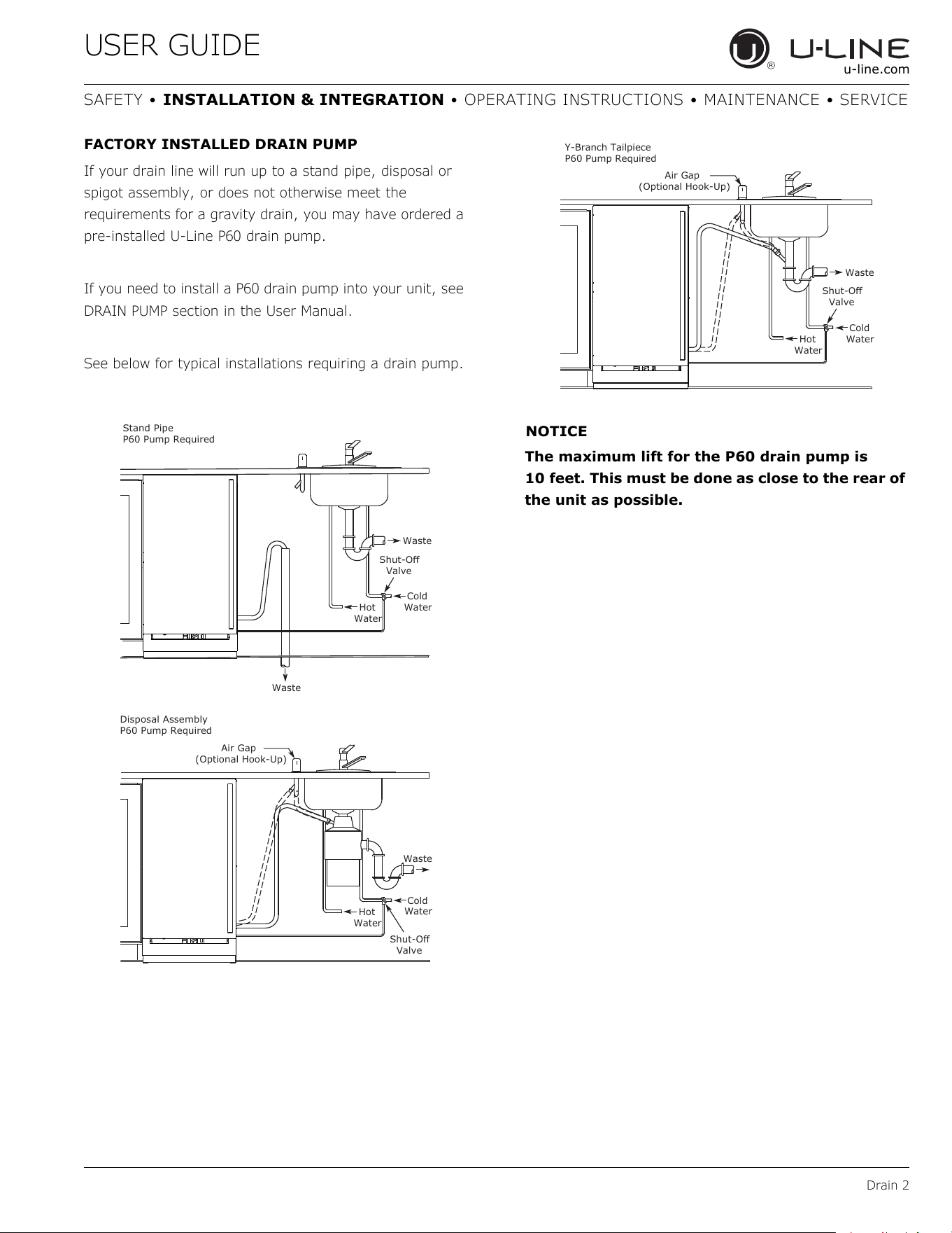
FACTORY INSTALLED DRAIN PUMP
If your drain line will run up to a stand pipe, disposal or
spigot assembly, or does not otherwise meet the
requirements for a gravity drain, you may have ordered a
pre-installed U-Line P60 drain pump.
If you need to install a P60 drain pump into your unit, see
DRAIN PUMP section in the User Manual.
See below for typical installations requiring a drain pump.
NOTICE
The maximum lift for the P60 drain pump is
10 feet. This must be done as close to the rear of
the unit as possible.
Cold
Water
Hot
Water
Waste
Waste
6KXW2ɞ
Valve
Stand Pipe
P60 Pump Required
Air Gap
(Optional Hook-Up)
Cold
Water
Hot
Water
Waste
6KXW2ɞ
Valve
Disposal Assembly
P60 Pump Required
Waste
Cold
Wate
r
6KXW2ɞ
Valve
Hot
Water
Air Gap
(Optional Hook-Up)
Y-Branch Tailpiece
P60 Pump Required
14
USER GUIDE
Anti-Tip Bracket 1
u-line.com
SAFETY • INSTALLATION & INTEGRATION • OPERATING INSTRUCTIONS • MAINTENANCE • SERVICE
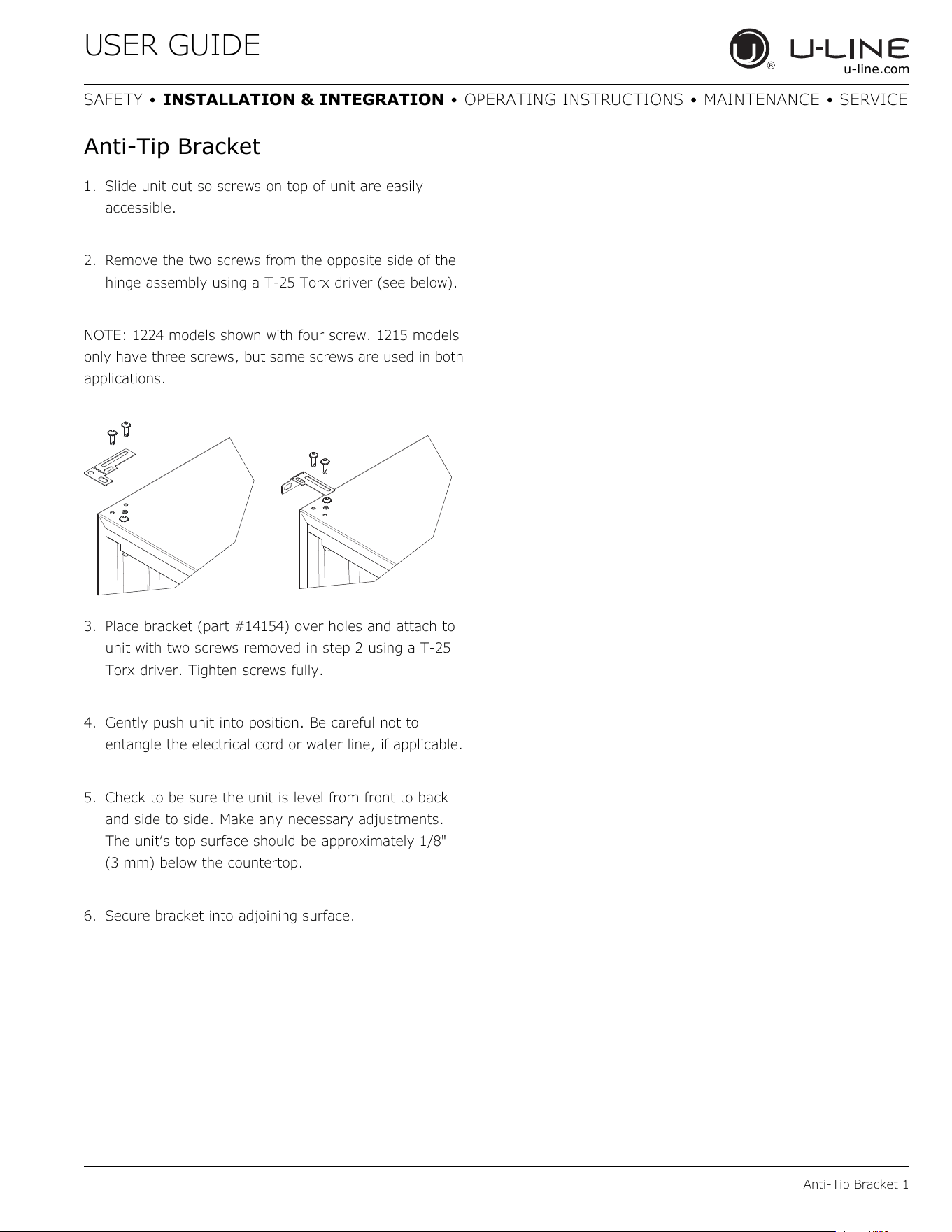
Anti-Tip Bracket
1. Slide unit out so screws on top of unit are easily
accessible.
2. Remove the two screws from the opposite side of the
hinge assembly using a T-25 Torx driver (see below).
NOTE: 1224 models shown with four screw. 1215 models
only have three screws, but same screws are used in both
applications.
3. Place bracket (part #14154) over holes and attach to
unit with two screws removed in step 2 using a T-25
Torx driver. Tighten screws fully.
4. Gently push unit into position. Be careful not to
entangle the electrical cord or water line, if applicable.
5. Check to be sure the unit is level from front to back
and side to side. Make any necessary adjustments.
The unit’s top surface should be approximately 1/8"
(3 mm) below the countertop.
6. Secure bracket into adjoining surface.
15
USER GUIDE
General Installation 1
u-line.com
SAFETY • INSTALLATION & INTEGRATION • OPERATING INSTRUCTIONS • MAINTENANCE • SERVICE
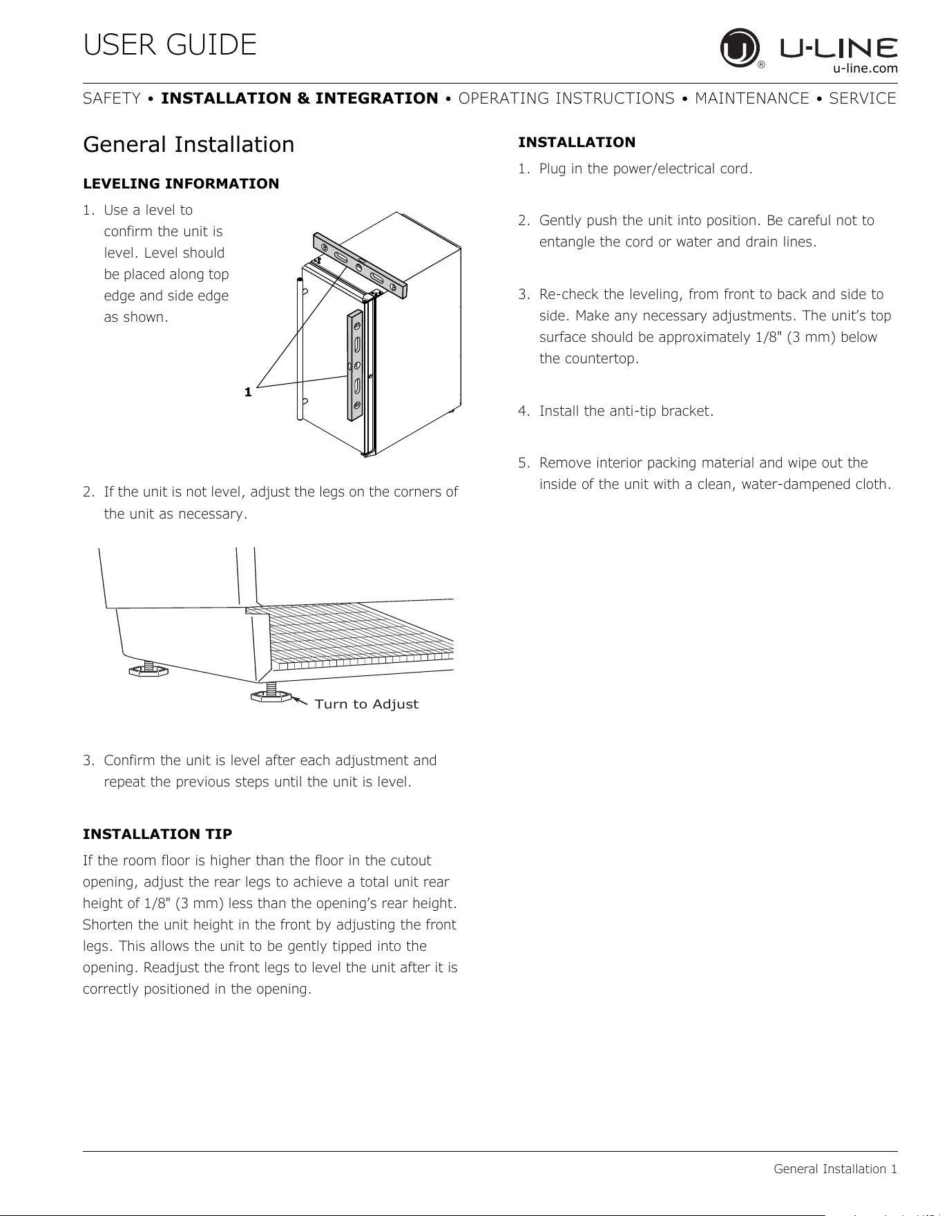
General Installation
LEVELING INFORMATION
1. Use a level to
confirm the unit is
level. Level should
be placed along top
edge and side edge
as shown.
2. If the unit is not level, adjust the legs on the corners of
the unit as necessary.
3. Confirm the unit is level after each adjustment and
repeat the previous steps until the unit is level.
INSTALLATION TIP
If the room floor is higher than the floor in the cutout
opening, adjust the rear legs to achieve a total unit rear
height of 1/8" (3 mm) less than the opening’s rear height.
Shorten the unit height in the front by adjusting the front
legs. This allows the unit to be gently tipped into the
opening. Readjust the front legs to level the unit after it is
correctly positioned in the opening.
INSTALLATION
1. Plug in the power/electrical cord.
2. Gently push the unit into position. Be careful not to
entangle the cord or water and drain lines.
3. Re-check the leveling, from front to back and side to
side. Make any necessary adjustments. The unit’s top
surface should be approximately 1/8" (3 mm) below
the countertop.
4. Install the anti-tip bracket.
5. Remove interior packing material and wipe out the
inside of the unit with a clean, water-dampened cloth.
1
Turn to Adjust
16
USER GUIDE
Grille - Plinth Installation 1
u-line.com
SAFETY • INSTALLATION & INTEGRATION • OPERATING INSTRUCTIONS • MAINTENANCE • SERVICE
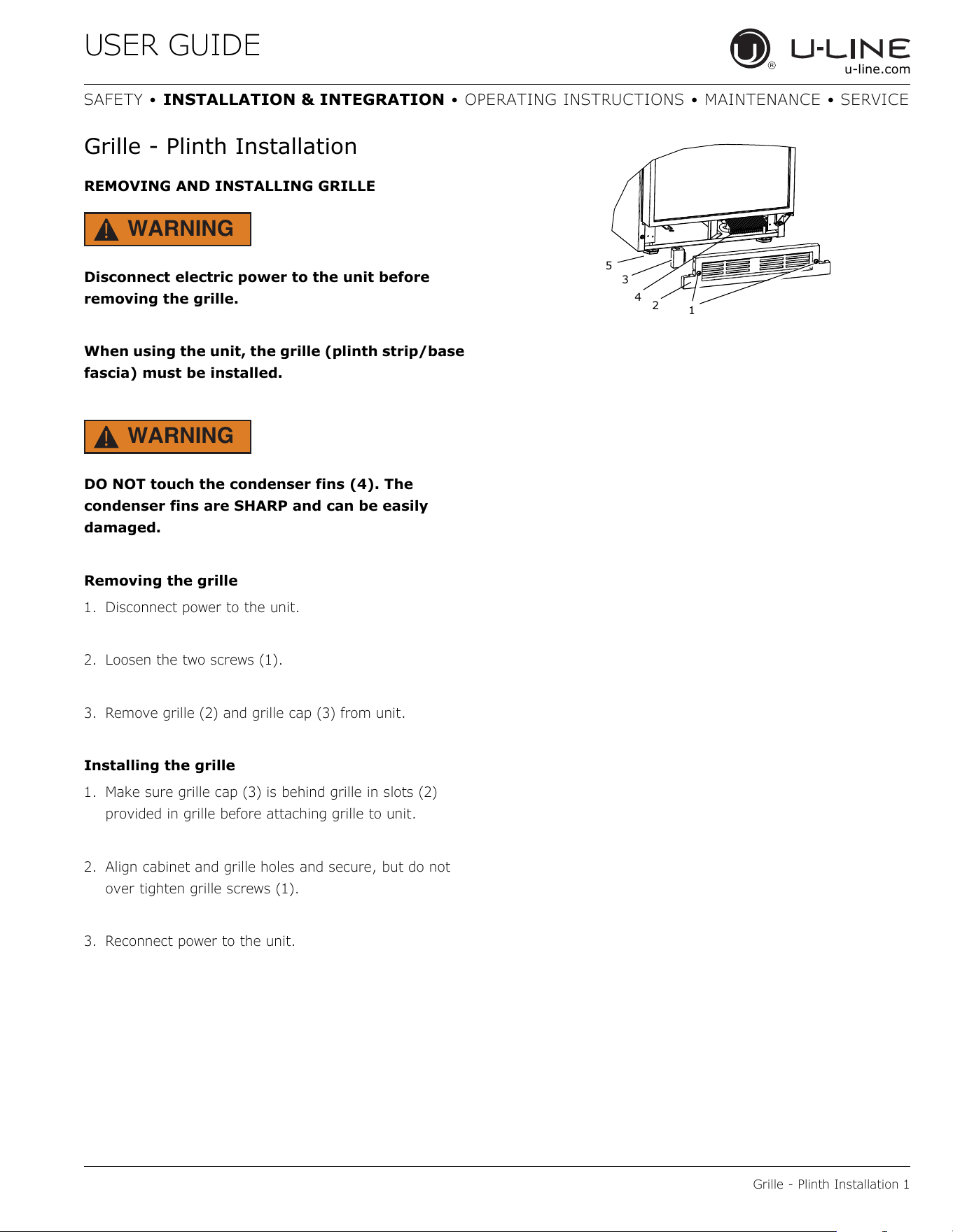
Grille - Plinth Installation
REMOVING AND INSTALLING GRILLE
WARNING
!
Disconnect electric power to the unit before
removing the grille.
When using the unit, the grille (plinth strip/base
fascia) must be installed.
WARNING
!
DO NOT touch the condenser fins (4). The
condenser fins are SHARP and can be easily
damaged.
Removing the grille
1. Disconnect power to the unit.
2. Loosen the two screws (1).
3. Remove grille (2) and grille cap (3) from unit.
Installing the grille
1. Make sure grille cap (3) is behind grille in slots (2)
provided in grille before attaching grille to unit.
2. Align cabinet and grille holes and secure, but do not
over tighten grille screws (1).
3. Reconnect power to the unit.
2
1
3
5
4
17
USER GUIDE
Door Swing 1
u-line.com
SAFETY • INSTALLATION & INTEGRATION • OPERATING INSTRUCTIONS • MAINTENANCE • SERVICE
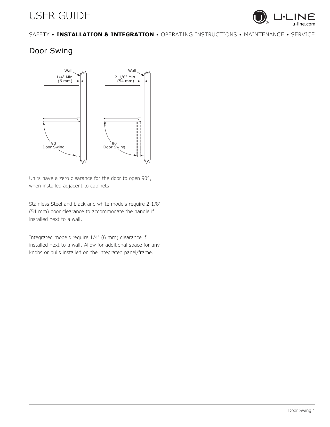
Door Swing
Units have a zero clearance for the door to open 90°,
when installed adjacent to cabinets.
Stainless Steel and black and white models require 2-1/8"
(54 mm) door clearance to accommodate the handle if
installed next to a wall.
Integrated models require 1/4" (6 mm) clearance if
installed next to a wall. Allow for additional space for any
knobs or pulls installed on the integrated panel/frame.
Wall Wall
90
Door Swing
90
Door Swing
2-1/8" Min.
(54 mm)
1/4" Min.
(6 mm)
18
USER GUIDE
Door Adjustments 1
u-line.com
SAFETY • INSTALLATION & INTEGRATION • OPERATING INSTRUCTIONS • MAINTENANCE • SERVICE
Door Adjustments
DOOR ALIGNMENT AND ADJUSTMENT
Align and adjust the door if it is not level or is not sealing
properly. If the door is not sealed, the unit may not cool
properly, or excessive frost may form in the interior.
NOTICE
Properly aligned, the door’s gasket should be
firmly in contact with the cabinet all the way
around the door (no gaps). Carefully examine
the door’s gasket to ensure that it is firmly in
contact with the cabinet. Also make sure the
door gasket is not pinched on the hinge side of
the door.
To align and adjust the door:
1. Loosen (do not remove) top and bottom hinge screws.
2. Align door squarely with cabinet.
3. Make sure gasket is firmly in contact with cabinet all
the way around the door (no gaps).
4. Tighten bottom hinge screws.
5. Tighten top hinge screws.
REVERSING THE DOOR
Location of the unit may make it desirable to mount the
door on the opposite side of the cabinet.
The hinge hardware will be removed and reinstalled on the
opposite side of the cabinet.
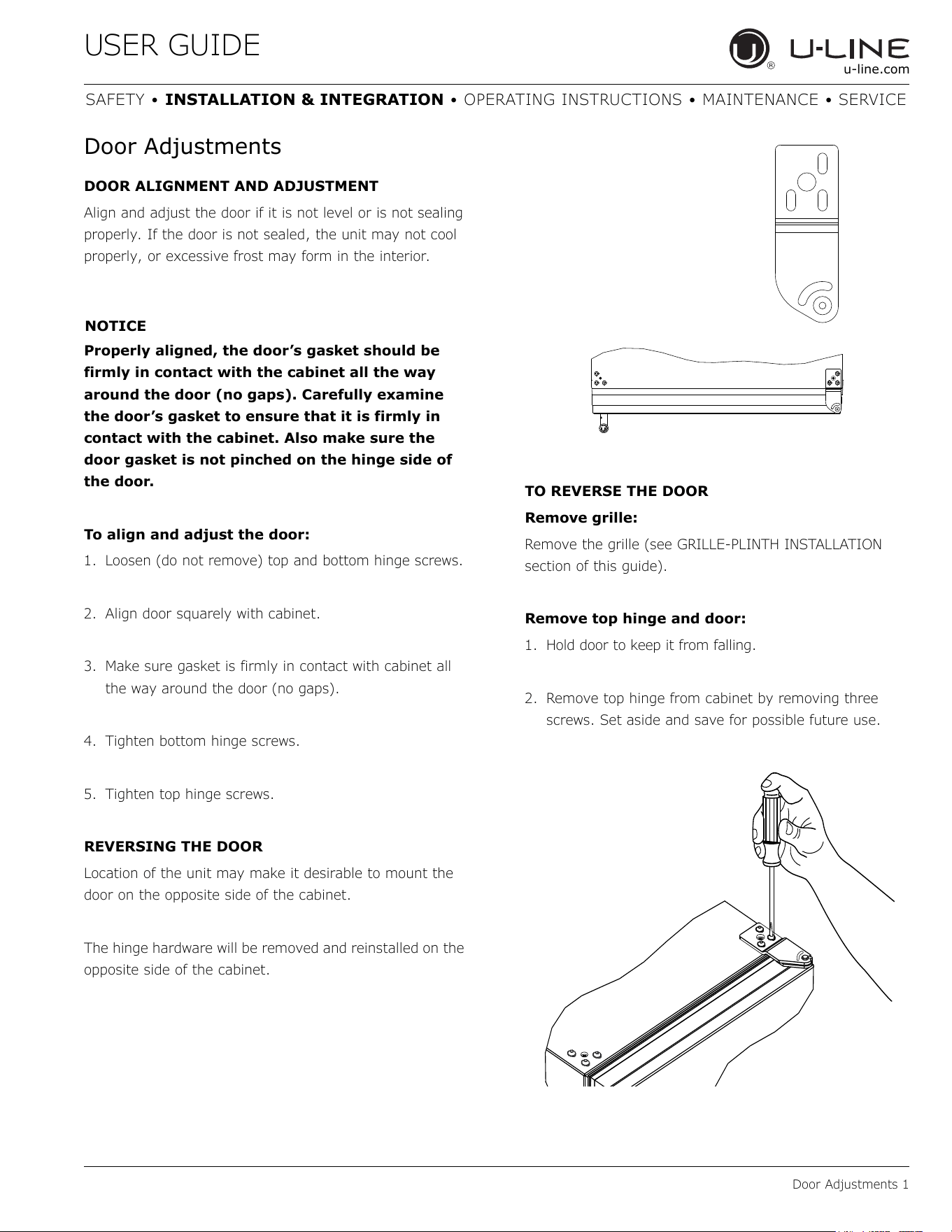
TO REVERSE THE DOOR
Remove grille:
Remove the grille (see GRILLE-PLINTH INSTALLATION
section of this guide).
Remove top hinge and door:
1. Hold door to keep it from falling.
2. Remove top hinge from cabinet by removing three
screws. Set aside and save for possible future use.
19
USER GUIDE
Door Adjustments 2
u-line.com
SAFETY • INSTALLATION & INTEGRATION • OPERATING INSTRUCTIONS • MAINTENANCE • SERVICE
3. Remove door by tilting forward and lifting door off
bottom hinge. Retain shoulder washers; they will
be reused.
4. Remove three screws from hinge holes on the opposite
side. Reinstall into holes where the hinge was
removed. Take care not to scratch cabinet.
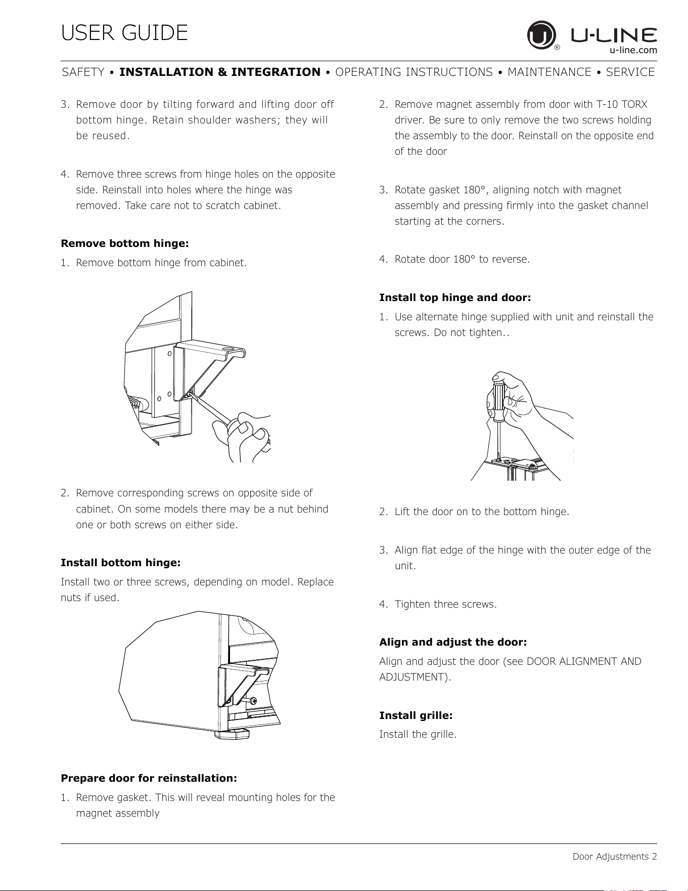
Remove bottom hinge:
1. Remove bottom hinge from cabinet.
2. Remove corresponding screws on opposite side of
cabinet. On some models there may be a nut behind
one or both screws on either side.
Install bottom hinge:
Install two or three screws, depending on model. Replace
nuts if used.
Prepare door for reinstallation:
1. Remove gasket. This will reveal mounting holes for the
magnet assembly
2. Remove magnet assembly from door with T-10 TORX
driver. Be sure to only remove the two screws holding
the assembly to the door. Reinstall on the opposite end
of the door
3. Rotate gasket 180°, aligning notch with magnet
assembly and pressing firmly into the gasket channel
starting at the corners.
4. Rotate door 180° to reverse.
Install top hinge and door:
1. Use alternate hinge supplied with unit and reinstall the
screws. Do not tighten..
2. Lift the door on to the bottom hinge.
3. Align flat edge of the hinge with the outer edge of the
unit.
4. Tighten three screws.
Align and adjust the door:
Align and adjust the door (see DOOR ALIGNMENT AND
ADJUSTMENT).
Install grille:
Install the grille.
20
USER GUIDE
First Use
u-line.com
First Use
All U-Line controls are preset at the factory. Initial startup
requires no adjustments. See CONTROL OPERATION
section for more details.
NOTICE
U-Line recommends discarding the ice produced
during the first two to three hours of operation
to avoid possible dirt or scale that may dislodge
from the water line.
When plugged in, the unit will begin operating under the
factory default settings. If the unit was turned off during
installation, simply press and the unit will immediately
switch on. To turn the unit off, press and release.
21
USER GUIDE
Control Operation 1
u-line.com
SAFETY • INSTALLATION & INTEGRATION • OPERATING INSTRUCTIONS • MAINTENANCE • SERVICE
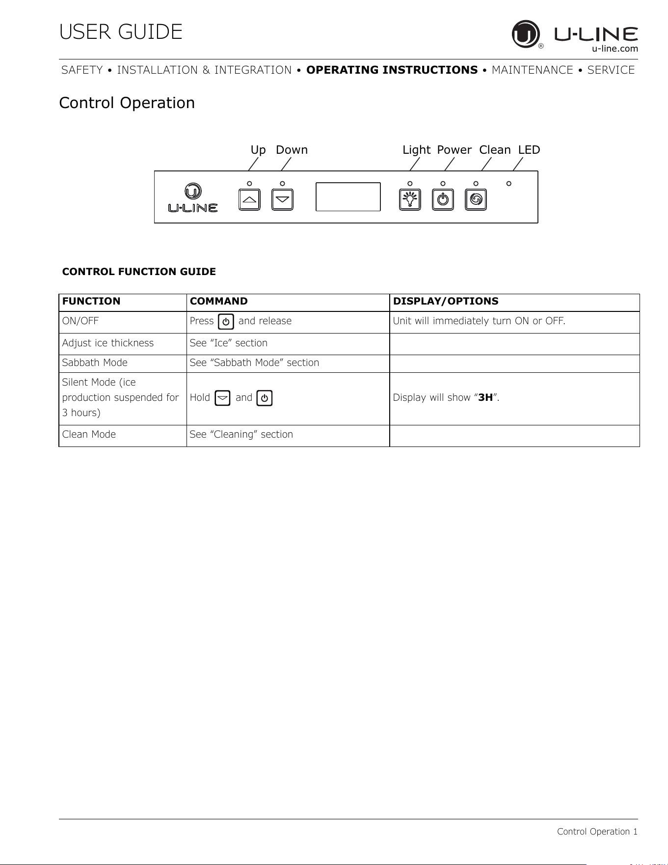
Control Operation
Up Down Light Power Clean
LED
CONTROL FUNCTION GUIDE
FUNCTION COMMAND DISPLAY/OPTIONS
ON/OFF Press and release Unit will immediately turn ON or OFF.
Adjust ice thickness See “Ice” section
Sabbath Mode See “Sabbath Mode” section
Silent Mode (ice
production suspended for
3 hours)
Hold and Display will show “3H”.
Clean Mode See “Cleaning” section
22
USER GUIDE
Ice 1
u-line.com
SAFETY • INSTALLATION & INTEGRATION • OPERATING INSTRUCTIONS • MAINTENANCE • SERVICE
Ice
ICE CUBE THICKNESS ADJUSTMENT
NOTICE
Ice thickness adjustment should only be made
one increment at a time. Allow ice maker
production to stabilize for 24 hours before
rechecking ice thickness.
Ice is produced in layers resulting in a clear cube. Ice in
bin may develop surface frost which disappears when cube
is placed in liquid.
Ice cubes in any given batch will vary, so it is necessary
to choose cubes from the sample area for comparison
when making adjustments.
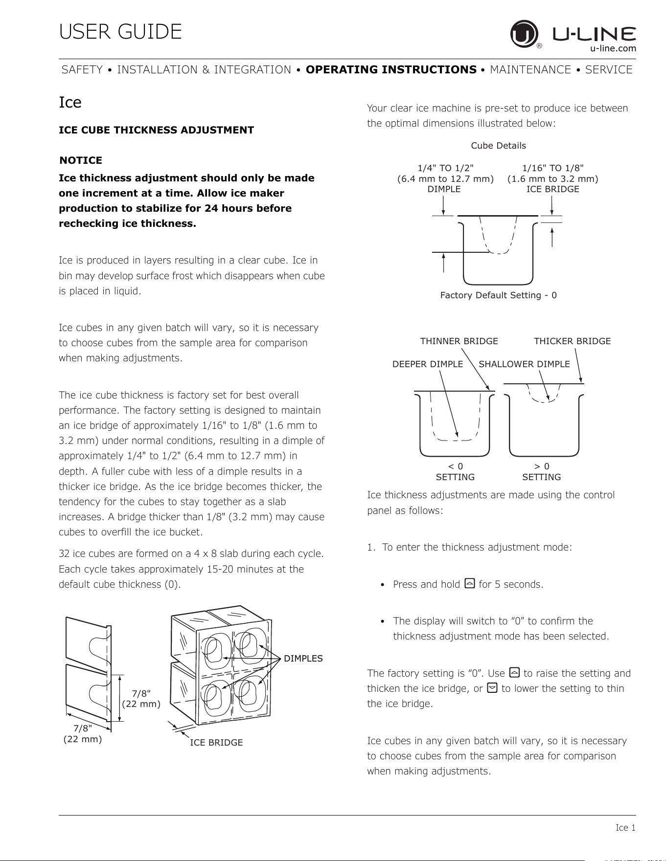
The ice cube thickness is factory set for best overall
performance. The factory setting is designed to maintain
an ice bridge of approximately 1/16" to 1/8" (1.6 mm to
3.2 mm) under normal conditions, resulting in a dimple of
approximately 1/4" to 1/2" (6.4 mm to 12.7 mm) in
depth. A fuller cube with less of a dimple results in a
thicker ice bridge. As the ice bridge becomes thicker, the
tendency for the cubes to stay together as a slab
increases. A bridge thicker than 1/8" (3.2 mm) may cause
cubes to overfill the ice bucket.
32 ice cubes are formed on a 4 x 8 slab during each cycle.
Each cycle takes approximately 15-20 minutes at the
default cube thickness (0).
Your clear ice machine is pre-set to produce ice between
the optimal dimensions illustrated below:
Ice thickness adjustments are made using the control
panel as follows:
1. To enter the thickness adjustment mode:
• Press and hold for 5 seconds.
• The display will switch to “0” to confirm the
thickness adjustment mode has been selected.
The factory setting is “0”. Use to raise the setting and
thicken the ice bridge, or to lower the setting to thin
the ice bridge.
Ice cubes in any given batch will vary, so it is necessary
to choose cubes from the sample area for comparison
when making adjustments.
DIMPLES
ICE BRIDGE
7/8"
(22 mm)
7/8"
(22 mm)
THINNER BRIDGE
THICKER BRIDGE
DEEPER DIMPLE
SHALLOWER DIMPLE
1/4" TO 1/2"
(6.4 mm to 12.7 mm)
DIMPLE
1/16" TO 1/8"
(1.6 mm to 3.2 mm)
ICE BRIDGE
Cube Details
Factory Default Setting - 0
< 0
SETTING
> 0
SETTING
23
USER GUIDE
Sabbath Mode 1
u-line.com
SAFETY • INSTALLATION & INTEGRATION • OPERATING INSTRUCTIONS • MAINTENANCE • SERVICE
L
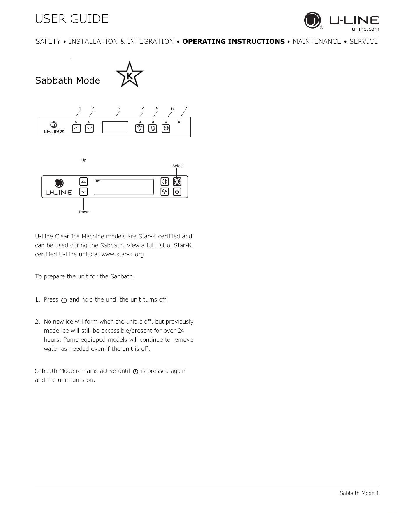
Sabbath Mode
U-Line Clear Ice Machine models are Star-K certified and
can be used during the Sabbath. View a full list of Star-K
certified U-Line units at www.star-k.org.
To prepare the unit for the Sabbath:
1. Press and hold the until the unit turns off.
2. No new ice will form when the unit is off, but previously
made ice will still be accessible/present for over 24
hours. Pump equipped models will continue to remove
water as needed even if the unit is off.
Sabbath Mode remains active until is pressed again
and the unit turns on.
12 3456 7
Up
Select
Down
24
USER GUIDE
Airflow and Product Loading 1
u-line.com
SAFETY • INSTALLATION & INTEGRATION • OPERATING INSTRUCTIONS • MAINTENANCE • SERVICE
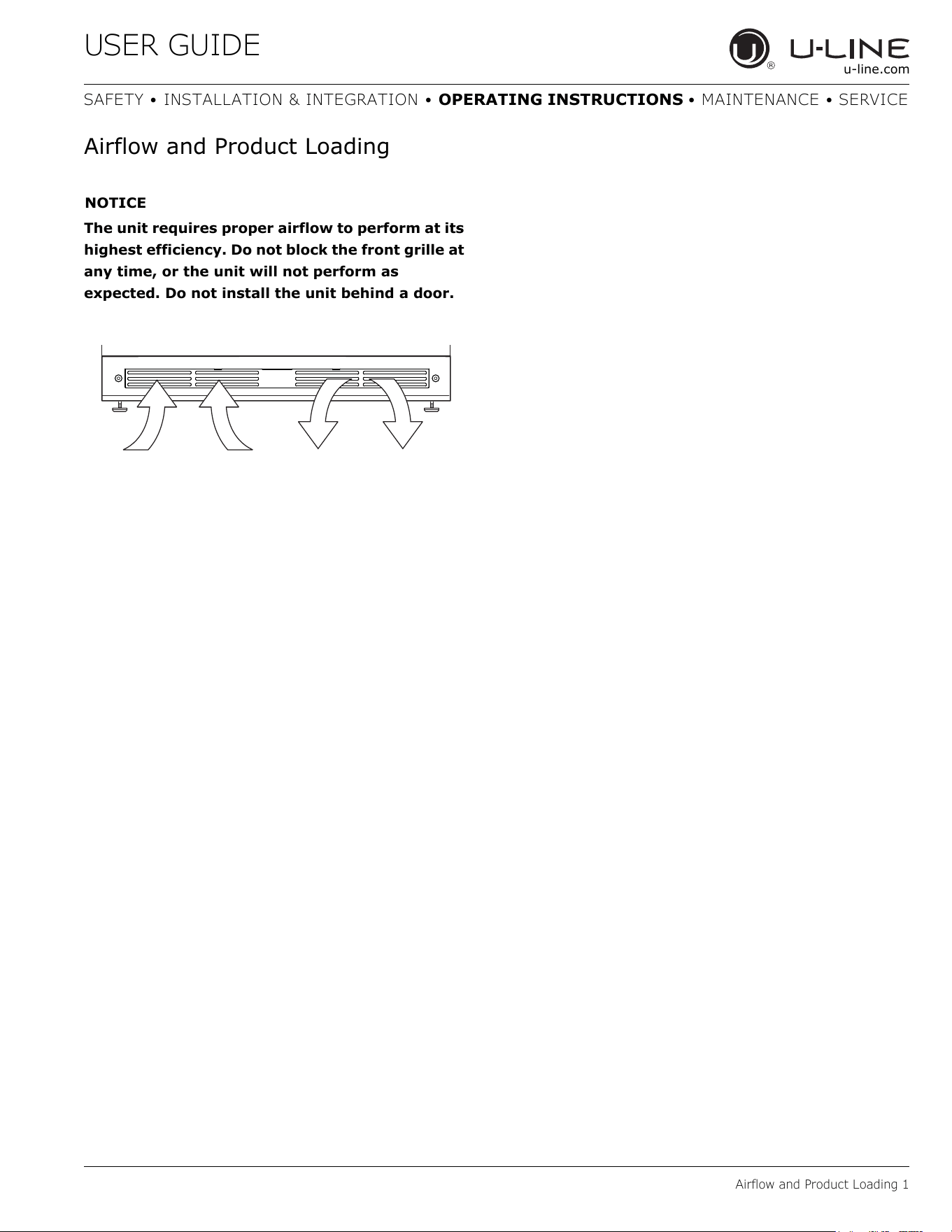
Airflow and Product Loading
NOTICE
The unit requires proper airflow to perform at its
highest efficiency. Do not block the front grille at
any time, or the unit will not perform as
expected. Do not install the unit behind a door.
25
USER GUIDE
Cleaning 1
u-line.com
SAFETY • INSTALLATION & INTEGRATION • OPERATING INSTRUCTIONS • MAINTENANCE • SERVICE
Cleaning
EXTERIOR CLEANING
Vinyl Clad (Black or White) Models
Clean surfaces with a mild detergent and warm water
solution. Do not use solvent-based or abrasive cleaners.
Use a soft sponge and rinse with clean water. Wipe with a
soft, clean towel to prevent water spotting.
Clean any glass surfaces with a non-chlorine glass
cleaner.
Stainless Models
Stainless door panels, handles and frames can discolor
when exposed to chlorine gas, pool chemicals, saltwater
or cleaners with bleach.
Keep your stainless unit looking new by cleaning with a
good quality all-in-one stainless steel cleaner and polish
monthly. For best results use Claire
®
Stainless Steel
Polish and Cleaner. Comparable products are acceptable.
Frequent cleaning will remove surface contamination that
could lead to rust. Some installations may require cleaning
weekly.
Do not clean with steel wool pads.
Do not use stainless steel cleaners or polishes on
any glass surfaces.
Clean any glass surfaces with a non-chlorine glass
cleaner.
Do not use cleaners not specifically intended for
stainless steel on stainless surfaces (this
includes glass, tile and counter cleaners).
If any surface discoloring or rusting appears, clean it
quickly with Bon-Ami
®
or Barkeepers Friend Cleanser
®
and
a nonabrasive cloth. Always clean with the grain. Always
finish with Claire
®
Stainless Steel Polish and Cleaner or
comparable product to prevent further problems.
Using abrasive pads such as ScotchBrite™ will
cause the graining in the stainless steel to
become blurred.
Rust not cleaned up promptly can penetrate the
surface of the stainless steel and complete
removal of the rust may not be possible.
Integrated Models
To clean integrated panels, use household cleaner per the
cabinet manufacturer’s recommendations.
INTERIOR CLEANING
Disconnect power to the unit.
Clean the interior and all removed components using a
mild nonabrasive detergent and warm water solution
applied with a soft sponge or non-abrasive cloth.
Rinse the interior using a soft sponge and clean water.
Do not use any solvent-based or abrasive
cleaners. These types of cleaners may transfer taste
and/or odor to the interior products and damage or
discolor the interior.
CLEAR ICE MACHINE CLEANING CYCLE
Your U-Line clear ice machine has an automatic clean
alert function. Cleaning cycles should be run as notified.
Otherwise, to maintain operational efficiency the unit
should be cleaned every three months. Depending on
water conditions, more frequent cleaning may be
necessary. If the ice machine requires more frequent
cleaning, consult a plumber to test the water quality and
recommend appropriate treatment.
CAUTION
!
Wear rubber gloves and safety goggles and/or
face shield when handling Ice Machine Cleaner.
26
USER GUIDE
Cleaning 2
u-line.com
SAFETY • INSTALLATION & INTEGRATION • OPERATING INSTRUCTIONS • MAINTENANCE • SERVICE
NOTICE
Use only U-Line Ice Machine Cleaner (Part No.
37050, available from your dealer or direct from
your local parts distributor. To locate a parts
distributor near you, visit www.u-line.com. It is
a violation of federal law to use this solution in a
manner inconsistent with its labeling. Use of any
other cleaner can ruin the finish of the
evaporator and will void the warranty. Read and
understand all labels printed on the package
before use.
U-Line Ice Machine Cleaner is used to remove lime scale
and other mineral deposits. Refer to the following steps to
initiate the self-cleaning cycle.
CAUTION
!
Never use anything
to force ice from the
evaporator. Damage
may result.
1. Turn the ice
machine off and
allow any ice to melt
off of the
evaporator.
2. Remove all ice from the storage bin.
3. Remove evaporator cover.
4. Remove the standpipe by lifting it up while using a
slight back and forth motion to loosen it from the drain
hole. The water in the reservoir will flow down the
drain.
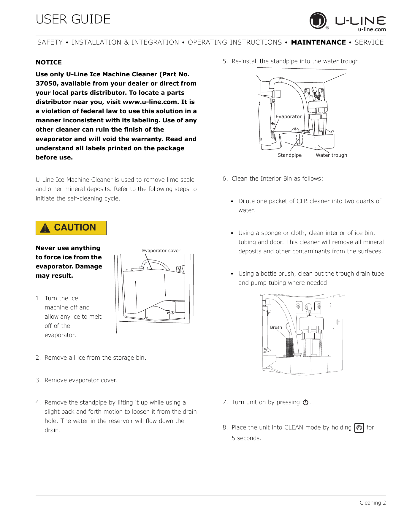
5. Re-install the standpipe into the water trough.
6. Clean the Interior Bin as follows:
• Dilute one packet of CLR cleaner into two quarts of
water.
• Using a sponge or cloth, clean interior of ice bin,
tubing and door. This cleaner will remove all mineral
deposits and other contaminants from the surfaces.
• Using a bottle brush, clean out the trough drain tube
and pump tubing where needed.
7. Turn unit on by pressing .
8. Place the unit into CLEAN mode by holding for
5seconds.
Evaporator cover
Standpipe
Evaporator
Water trough
Brush
27
USER GUIDE
Cleaning 3
u-line.com
SAFETY • INSTALLATION & INTEGRATION • OPERATING INSTRUCTIONS • MAINTENANCE • SERVICE
9. When water begins flowing over the evaporator
(approximately 3 minutes), pour 1 packet of CLR
cleaner into the water trough. The cleaning process will
last approximately 45 minutes.
10.Dilute 1 tablespoon bleach in 1 gallon of warm water.
Apply this solution to the entire inside of the storage
area. Then rinse thoroughly with water.
The unit will resume operation approximately 15 minutes
after the automated cleaning process is completed. The
water fill valve will energize, fill the water reservoir, and
shut-off after three minutes. The compressor begins to
operate and water flows over the evaporator assembly (ice
mold). Initially, the water flow may not be uniform,
causing uneven sized cubes or water to spill into the ice
storage bin. This is a normal situation that will correct
itself within the first 24 hours of operation.
NOTICE
Discard all ice produced in the first harvest.
Should power to the unit be interrupted during
the self-clean cycle, it will be necessary to
repeat the complete cleaning cycle after power
is restored.
REFRESH KIT
Due to variations in water quality or inadequate
maintenance your unit may become excessively coated in
lime scale or calcium. U-Line offers a cost effective
refresh kit which replaces many interior components and
will return your unit to like new condition. Refresh kits
may be ordered from your local distributor and installed
by your local service company. For information on your
local distributor or service company please visit
www.u-line.com.
28
USER GUIDE
Cleaning Condenser 1
u-line.com
SAFETY • INSTALLATION & INTEGRATION • OPERATING INSTRUCTIONS • MAINTENANCE • SERVICE
Cleaning Condenser
INTERVAL - EVERY SIX MONTHS
To maintain operational efficiency, keep the front grille
free of dust and lint, and clean the condenser when
necessary. Depending on environmental conditions, more
or less frequent cleaning may be necessary.
WARNING
!
Disconnect electric power to the unit before
cleaning the condenser.
NOTICE
DO NOT use any type of cleaner on the
condenser unit. Condenser may be cleaned using
a vacuum, soft brush or compressed air.
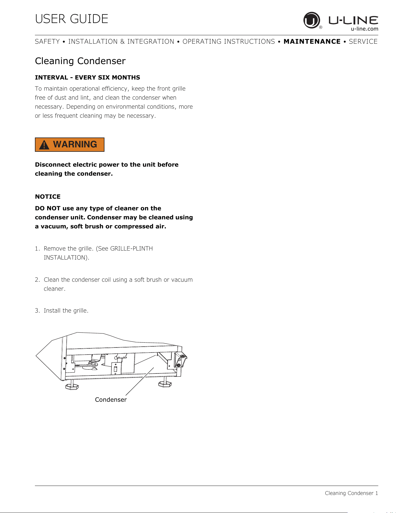
1. Remove the grille. (See GRILLE-PLINTH
INSTALLATION).
2. Clean the condenser coil using a soft brush or vacuum
cleaner.
3. Install the grille.
Condenser
29
USER GUIDE
Extended Non-Use 1
u-line.com
SAFETY • INSTALLATION & INTEGRATION • OPERATING INSTRUCTIONS • MAINTENANCE • SERVICE
Extended Non-Use
VACATION/HOLIDAY, PROLONGED SHUTDOWN
The following steps are recommended for periods of
extended non-use:
1. Remove all consumable content from the unit.
2. Disconnect the power cord from its outlet/socket and
leave it disconnected until the unit is returned to
service.
3. Turn off the water supply.
4. If ice is on the evaporator, allow ice to thaw naturally.
5. Clean and dry the interior of the cabinet. Ensure all
water has been removed from the unit.
6. Disconnect the water and drain line (if applicable)
making sure all water is removed from the lines.
7. The door must remain open to prevent formation of
mold and mildew. Open door a minimum of 2"
(50 mm) to provide the necessary ventilation.
WINTERIZATION
If the unit will be exposed to temperatures of 40°F (5°C)
or less, the steps above must be followed. In addition, P60
drain pumps in clear ice machines must be drained
according to the following procedure:
1. Remove the drain pump from the ice machine.
2. Drain the water in the pump’s reservoir by turning the
pump upside down and allowing the water to drain
through the pump’s inlet and vent tube fittings.
3. After water is drained, reinstall the drain pump and
reattach all connections.
For questions regarding winterization, please
call U-Line at +1.800.779.2547.
CAUTION
!
Damage caused by freezing temperatures is not
covered by the warranty.
Do not put anti-freeze in your unit.
30
USER GUIDE
Troubleshooting 1
u-line.com
SAFETY • INSTALLATION & INTEGRATION • OPERATING INSTRUCTIONS • MAINTENANCE • SERVICE
Troubleshooting
BEFORE CALLING FOR SERVICE
If you think your U-Line product is malfunctioning, read
the CONTROL OPERATION section to clearly understand
the function of the control.
If the problem persists, read the NORMAL OPERATING
SOUNDS and TROUBLESHOOTING GUIDE sections below
to help you quickly identify common problems and
possible causes and remedies. Most often, this will resolve
the problem without the need to call for service.
IF SERVICE IS REQUIRED
If you do not understand a troubleshooting remedy, or
your product needs service, contact U-Line Corporation
directly at +1.800.779.2547.
When you call, you will need your product Model and
Serial Numbers. This information appears on the Model
and Serial number plate located on the upper right or rear
wall of the interior of your product.
NORMAL OPERATING SOUNDS
All models incorporate rigid foam insulated cabinets to
provide high thermal efficiency and maximum sound
reduction for its internal working components. Despite this
technology, your model may make sounds that are
unfamiliar.
Normal operating sounds may be more noticeable because
of the unit’s environment. Hard surfaces such as cabinets,
wood, vinyl or tiled floors and paneled walls have a
tendency to reflect normal appliance operating noises.
Listed below are common refrigeration components with a
brief description of the normal operating sounds they
make. NOTE: Your product may not contain all the
components listed.
• Compressor: The compressor makes a hum or pulsing
sound that may be heard when it operates.
• Evaporator: Refrigerant flowing through an evaporator
may sound like boiling liquid.
• Condenser Fan: Air moving through a condenser may
be heard.
• Running Water: As your unit continues to produce ice
you will hear water flowing into the collection chambers
and running over the evaporator.
TROUBLESHOOTING GUIDE
DANGER
!
ELECTROCUTION HAZARD. Never attempt to
repair or perform maintenance on the unit
before disconnecting the main electrical power.
Troubleshooting - What to check when problems occur:
Problem Possible Cause and Remedy
Unit Does Not
Operate.
Electronic
Display Blank.
No electrical supply. Plug unit in or check
circuit breaker.
Display
Showing Error
Code.
If display shows error 10E or ER, check to
make sure door is sealing correctly. Make sure
to close door completely. If sealing the door
does not clear the error, contact U-Line service
for more information.
Unit Develops
Condensation
on External
Surfaces.
The unit is exposed to excessive humidity.
Moisture will dissipate as humidity levels
decrease.
Poor Ice
Quality.
Unit may not be level. Check if unit is level.
Ice maker system may be dirty. Clean the ice
maker.
No Ice
Production.
Ensure water is being supplied to the unit.
Verify the ice making unit is turned on.
Not Enough
Ice.
Ensure the condenser coil is clean and free of
any dirt or lint build-up.
Water in Ice
Bin.
Drain may be restricted, ensure drain is free of
foreign debris.
31
USER GUIDE
Wire Diagram 1
u-line.com
SAFETY • INSTALLATION & INTEGRATION • OPERATING INSTRUCTIONS • MAINTENANCE • SERVICE
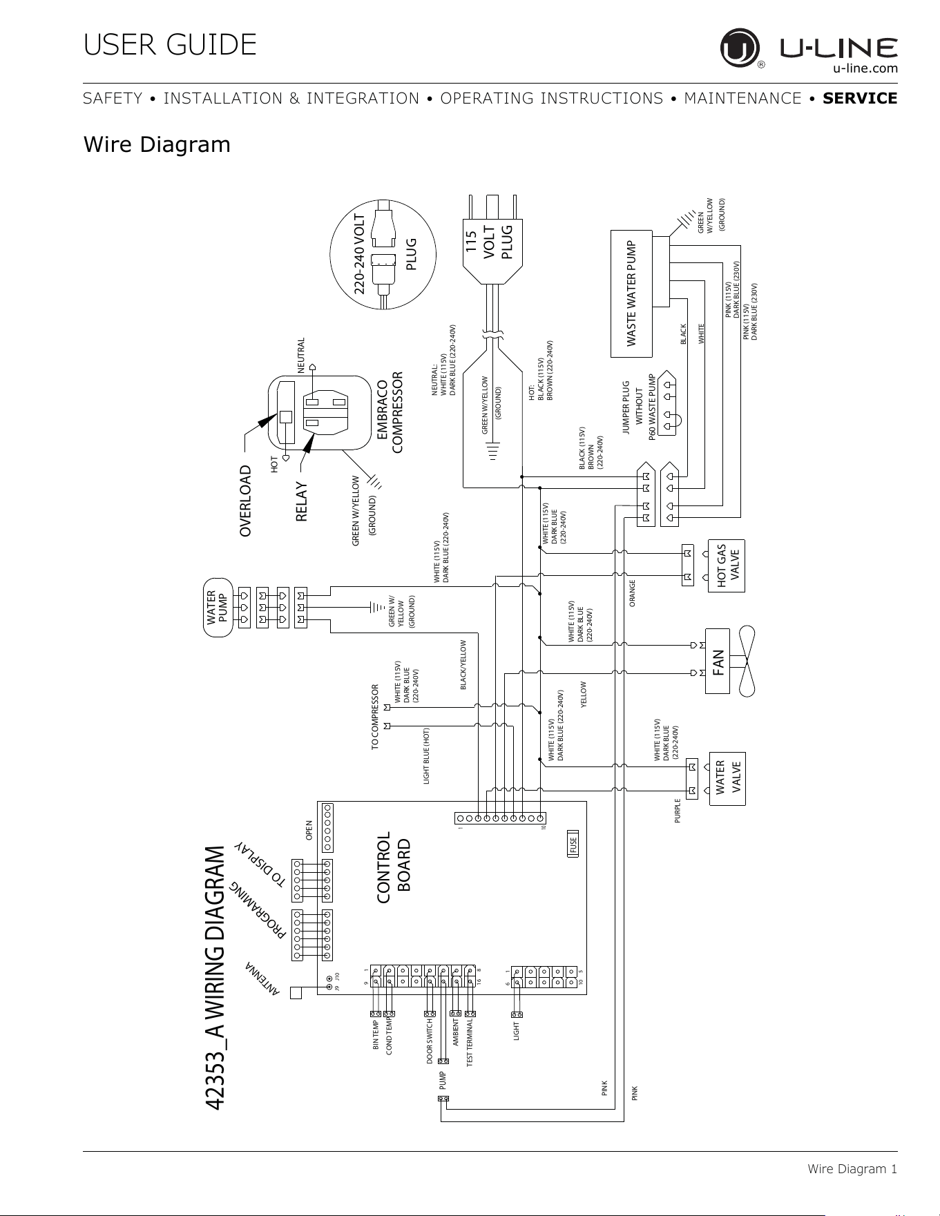
Wire Diagram
42353_A WIRING DIAGRAM
GREEN W/YELLOW
(GROUND)
WASTE WATER PUMP
JUMPER PLUG
WITHOUT
P60 WASTE PUMP
GREEN
W/YELLOW
(GROUND)
BLACK
WHITE
PINK (115V)
PINK (115V)
PINK
HOT GAS
VALVE
WATER
VALVE
GREEN W/
YELLOW
(GROUND)
TO COMPRESSOR
BLACK/YELLOW
ORANGE
WATER
PUMP
OVERLOAD
NEUTRAL
HOT
RELAY
EMBRACO
COMPRESSOR
GREEN W/YELLOW
(GROUND)
PINK
LIGHT BLUE (HOT)
WHITE (115V)
DARK BLUE
(220-240V)
WHITE (115V)
DARK BLUE
(220-240V)
PURPLE
PUMP
BLACK (115V)
BROWN
(220-240V)
FAN
115
VOLT
PLUG
CONTROL
BOARD
BIN TEMP
FUSE
16
8
9
1
6
1
10
5
COND TEMP
TEST TERMINAL
LIGHT
PROGRAMING
TO DISPLAY
DOOR SWITCH
OPEN
J9
J10
ANTENNA
1
10
220-240 VOLT
PLUG
DARK BLUE (230V)
DARK BLUE (230V)
YELLOW
WHITE (115V)
DARK BLUE
(220-240V)
WHITE (115V)
DARK BLUE (220-240V)
WHITE (115V)
DARK BLUE (220-240V)
WHITE (115V)
DARK BLUE
(220-240V)
HOT:
BLACK (115V)
BROWN (220-240V)
NEUTRAL:
WHITE (115V)
DARK BLUE (220-240V)
AMBIENT
32
USER GUIDE
Product Liability 1
u-line.com
SAFETY • INSTALLATION & INTEGRATION • OPERATING INSTRUCTIONS • MAINTENANCE • SERVICE
Product Liability
Field service technicians are authorized to make an initial
assessment in the event of reported damages. If there are
any questions about the process involved, the technician
should call U-Line for further explanation.
While inspecting for defects or installation issues, photos
should be taken to document any damages or issues
found.
During the assessment, if the service technician is able to
find the source of the damage and it can be resolved by
replacement of a part, the servicer is authorized to
replace the part in question. The part that caused the
damage must be returned to U-Line in its entirety. The
part must be clearly labeled with the serial number of the
unit it was removed from, the date, and the servicer who
removed the part.
If the service technician determines the damage is the
result of installation issues (water connection/drain, etc.),
the consumer would be notified and the issues shall be
resolved at the direction of the consumer.
If damage is evident and the service technician is unable
to find the source, U-Line must be contacted at 1-800-
799-2547 for further direction
8900 N. 55th Street • Milwaukee, WI 53223
T: +1.414.354.0300 • F: +1.414.354.354.5696
Website: www.u-line.com
Right product. Right place.
Right temperature Since 1962.
33
USER GUIDE
Warranty Claims 1
u-line.com
SAFETY • INSTALLATION & INTEGRATION • OPERATING INSTRUCTIONS • MAINTENANCE • SERVICE
Warranty Claims
The following information defines the parameters for filing
a warranty claim:
• Valid serial number needed
• Valid model number needed
• Narda (or equivalent) form or submitted online at
www.u-line.com
• 60 day submittal deadline from date of completed
service
• Only one repair or unit per warranty claim
• Refrigerant should be labeled and included on the labor
submittal
• Door and water level adjustments are covered 30 days
from install date.
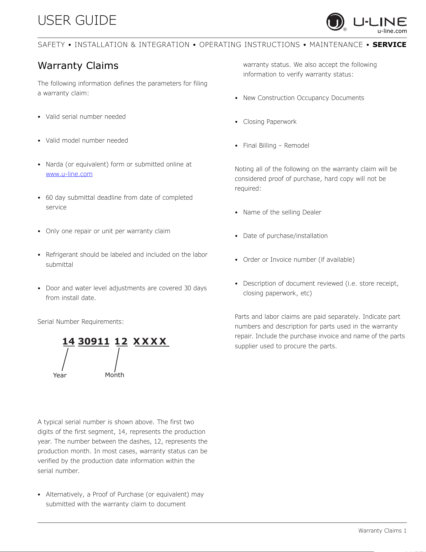
Serial Number Requirements:
A typical serial number is shown above. The first two
digits of the first segment, 14, represents the production
year. The number between the dashes, 12, represents the
production month. In most cases, warranty status can be
verified by the production date information within the
serial number.
• Alternatively, a Proof of Purchase (or equivalent) may
submitted with the warranty claim to document
warranty status. We also accept the following
information to verify warranty status:
• New Construction Occupancy Documents
•Closing Paperwork
• Final Billing – Remodel
Noting all of the following on the warranty claim will be
considered proof of purchase, hard copy will not be
required:
• Name of the selling Dealer
• Date of purchase/installation
• Order or Invoice number (if available)
• Description of document reviewed (i.e. store receipt,
closing paperwork, etc)
Parts and labor claims are paid separately. Indicate part
numbers and description for parts used in the warranty
repair. Include the purchase invoice and name of the parts
supplier used to procure the parts.
14 30911 12 XXXX
Year
Month
34
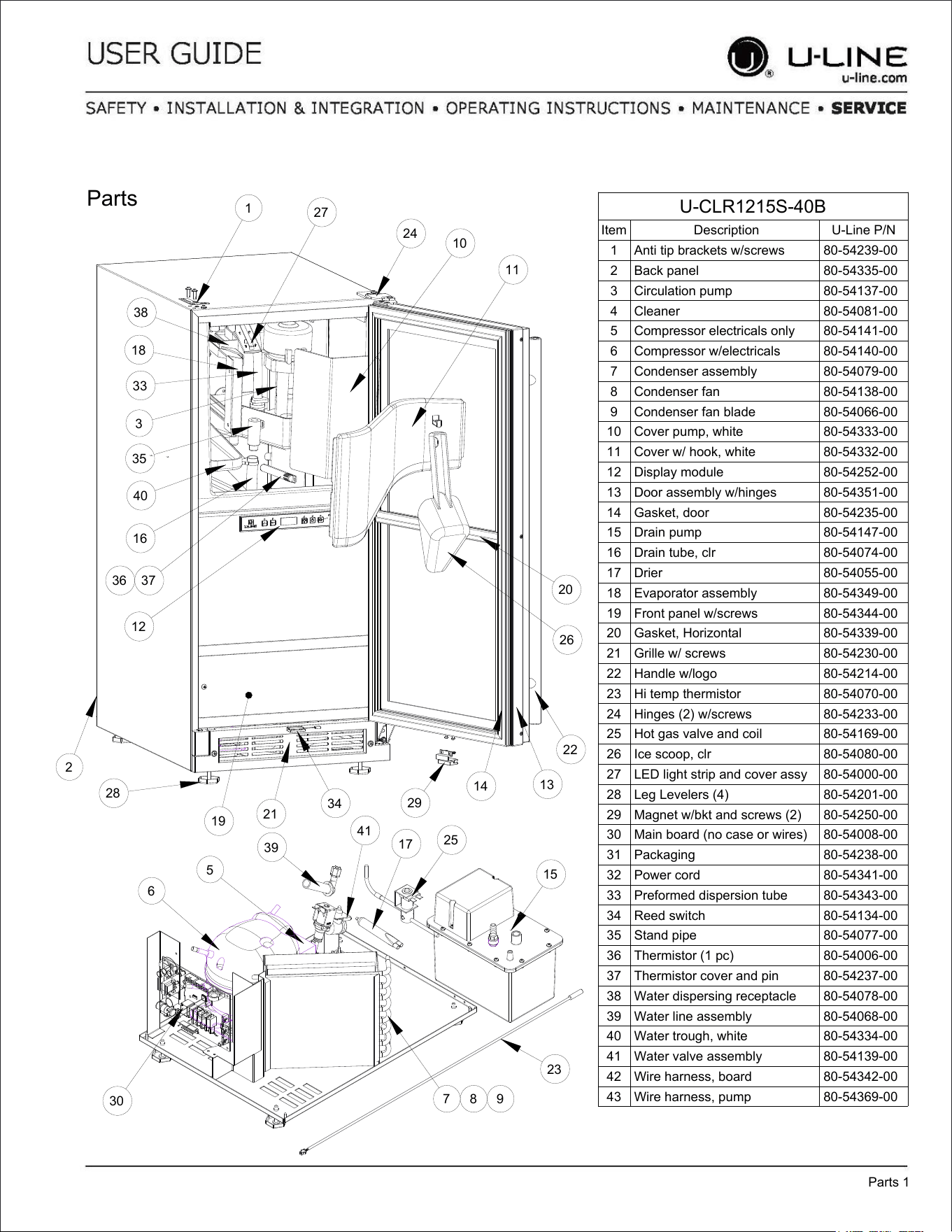
U-CLR1215S-40B
Item Description U-Line P/N
1 Anti tip brackets w/screws 80-54239-00
2 Back panel 80-54335-00
3 Circulation pump 80-54137-00
4 Cleaner 80-54081-00
5 Compressor electricals only 80-54141-00
6 Compressor w/electricals 80-54140-00
7 Condenser assembly 80-54079-00
8 Condenser fan 80-54138-00
9 Condenser fan blade 80-54066-00
10 Cover pump, white 80-54333-00
11 Cover w/ hook, white 80-54332-00
12 Display module 80-54252-00
13 Door assembly w/hinges 80-54351-00
14 Gasket, door 80-54235-00
15 Drain pump 80-54147-00
16 Drain tube, clr 80-54074-00
17 Drier 80-54055-00
18 Evaporator assembly 80-54349-00
19 Front panel w/screws 80-54344-00
20 Gasket, Horizontal 80-54339-00
21 Grille w/ screws 80-54230-00
22 Handle w/logo 80-54214-00
23 Hi temp thermistor 80-54070-00
24 Hinges (2) w/screws 80-54233-00
25 Hot gas valve and coil 80-54169-00
26 Ice scoop, clr 80-54080-00
27 LED light strip and cover assy 80-54000-00
28 Leg Levelers (4) 80-54201-00
29 Magnet w/bkt and screws (2) 80-54250-00
30 Main board (no case or wires) 80-54008-00
31 Packaging 80-54238-00
32 Power cord 80-54341-00
33 Preformed dispersion tube 80-54343-00
34 Reed switch 80-54134-00
35 Stand pipe 80-54077-00
36 Thermistor (1 pc) 80-54006-00
37 Thermistor cover and pin 80-54237-00
38 Water dispersing receptacle 80-54078-00
39 Water line assembly 80-54068-00
40 Water trough, white 80-54334-00
41 Water valve assembly 80-54139-00
42 Wire harness, board 80-54342-00
43 Wire harness, pump 80-54369-00
Parts
Parts 1
1
27
24
10
11
20
26
22
13
14
29
34
21
19
28
2
38
18
33
35
40
16
36 37
12
3
6
5
39
41
17
25
7 8 9
30
23
15
35
USER GUIDE
Ordering Replacement Parts 1
u-line.com
SAFETY • INSTALLATION & INTEGRATION • OPERATING INSTRUCTIONS • MAINTENANCE • SERVICE
Ordering Replacement Parts
If you have a purchasing account, please utilize our
service website to order parts.
Orders may also be placed by Fax or phone. See our
contact information below:
www.U-LineService.com (with service login)
FAX Number: +1.414.354.5696
Phone Number: +1.800.779.2547
NOTICE
Use only genuine U-Line replacement parts. The
use of non-U-Line parts can reduce speed of ice
production, cause water to overflow from ice
maker mold, damage the unit, and void the
warranty.
Warranty parts will be shipped at no charge after U-Line
confirms warranty status. Please provide the model, serial
number, part number and part description. Some parts
will require color or voltage information.
If U-Line requires the return of original parts, we will
inform you when the parts order is taken. This
requirement will be noted on your packing list. A prepaid
shipping label will be included with the replacement part.
Please enclose a copy of the parts packing list and any
labor claims with your return. Please be sure the model
and serial numbers are legible on the paperwork. Tag the
part with the reported defect.
When ordering a non-warranty part, you will need an open
account and tax exemption on file at U-Line. Another
option would be to visit www.u-line.com to locate an
authorized parts distributor in your area.
36
USER GUIDE
System Diagnosis Guide 1
u-line.com
SAFETY • INSTALLATION & INTEGRATION • OPERATING INSTRUCTIONS • MAINTENANCE • SERVICE
System Diagnosis Guide
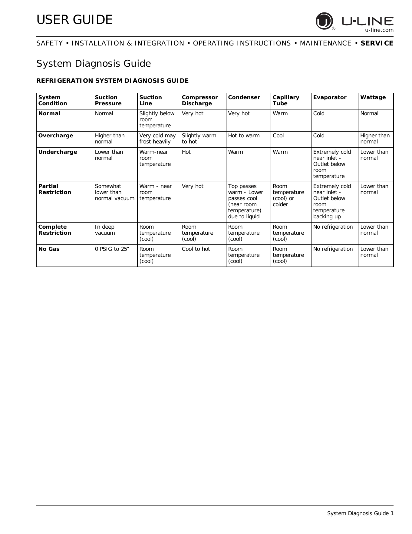
REFRIGERATION SYSTEM DIAGNOSIS GUIDE
System
Condition
Suction
Pressure
Suction
Line
Compressor
Discharge
Condenser Capillary
Tube
Evaporator Wattage
Normal Normal Slightly below
room
temperature
Very hot Very hot Warm Cold Normal
Overcharge Higher than
normal
Very cold may
frost heavily
Slightly warm
to hot
Hot to warm Cool Cold Higher than
normal
Undercharge Lower than
normal
Warm-near
room
temperature
Hot Warm Warm Extremely cold
near inlet -
Outlet below
room
temperature
Lower than
normal
Partial
Restriction
Somewhat
lower than
normal vacuum
Warm - near
room
temperature
Very hot Top passes
warm - Lower
passes cool
(near room
temperature)
due to liquid
Room
temperature
(cool) or
colder
Extremely cold
near inlet -
Outlet below
room
temperature
backing up
Lower than
normal
Complete
Restriction
In deep
vacuum
Room
temperature
(cool)
Room
temperature
(cool)
Room
temperature
(cool)
Room
temperature
(cool)
No refrigeration Lower than
normal
No Gas 0 PSIG to 25" Room
temperature
(cool)
Cool to hot Room
temperature
(cool)
Room
temperature
(cool)
No refrigeration Lower than
normal
37
USER GUIDE
Compressor Specifications 1
u-line.com
SAFETY • INSTALLATION & INTEGRATION • OPERATING INSTRUCTIONS • MAINTENANCE • SERVICE
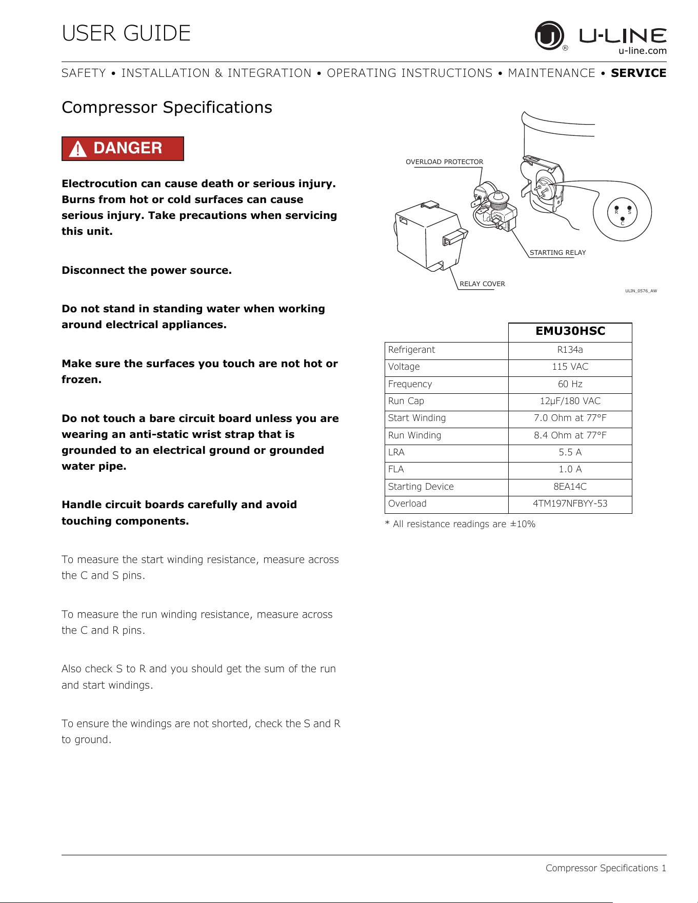
Compressor Specifications
DANGER
!
Electrocution can cause death or serious injury.
Burns from hot or cold surfaces can cause
serious injury. Take precautions when servicing
this unit.
Disconnect the power source.
Do not stand in standing water when working
around electrical appliances.
Make sure the surfaces you touch are not hot or
frozen.
Do not touch a bare circuit board unless you are
wearing an anti-static wrist strap that is
grounded to an electrical ground or grounded
water pipe.
Handle circuit boards carefully and avoid
touching components.
To measure the start winding resistance, measure across
the C and S pins.
To measure the run winding resistance, measure across
the C and R pins.
Also check S to R and you should get the sum of the run
and start windings.
To ensure the windings are not shorted, check the S and R
to ground.
* All resistance readings are ±10%
EMU30HSC
Refrigerant R134a
Voltage 115 VAC
Frequency 60 Hz
Run Cap 12μF/180 VAC
Start Winding 7.0 Ohm at 77°F
Run Winding 8.4 Ohm at 77°F
LRA 5.5 A
FLA 1.0 A
Starting Device 8EA14C
Overload 4TM197NFBYY-53
ULIN_0576_AW
RS
C
OVERLOAD PROTECTOR
STARTING RELAY
RELAY COVER
38
USER GUIDE
Troubleshooting - Extended 1
u-line.com
SAFETY • INSTALLATION & INTEGRATION • OPERATING INSTRUCTIONS • MAINTENANCE • SERVICE
Troubleshooting - Extended
SPECIFIC ERRORS AND ISSUES
The technically advanced diagnostic capabilities of the
electronic controls utilized on the 1200 and 2200 series
units allows for easy and thorough troubleshooting.
Navigation of the control is the key and is explained in the
CONTROL OPERATION section of the manual, along with
control button layout, control function descriptions, a
service mode menu and service menu selection
explanations.
Verification of temperature and thermistor performance
can be identified by directly viewing thermistor readings in
the service mode.
Component failure issues can be identified through service
mode menu #19, “Component Testing.” Individual
components can be switched on and off to check for both
proper function of a specific component and also delivery
of supply voltage to the components through the relays
and DC outputs located on the relay/power board.
Included in this section are some diagnostic tips and of
course, if additional help is required please contact the
U-Line Corp, “Customer Care Facility” at +1.800.779.2547
for assistance.
39
USER GUIDE
Troubleshooting - Extended 2
u-line.com
SAFETY • INSTALLATION & INTEGRATION • OPERATING INSTRUCTIONS • MAINTENANCE • SERVICE
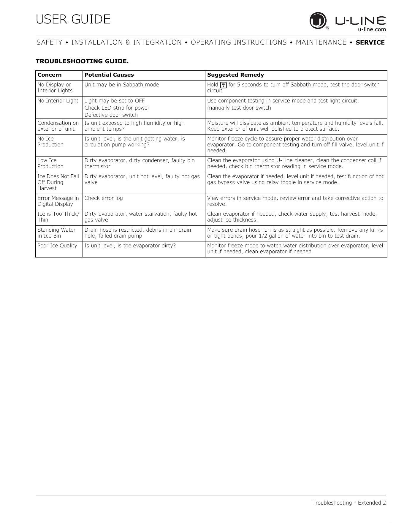
TROUBLESHOOTING GUIDE.
Concern Potential Causes Suggested Remedy
No Display or
Interior Lights
Unit may be in Sabbath mode Hold for 5 seconds to turn off Sabbath mode, test the door switch
circuit
No Interior Light Light may be set to OFF
Check LED strip for power
Defective door switch
Use component testing in service mode and test light circuit,
manually test door switch
Condensation on
exterior of unit
Is unit exposed to high humidity or high
ambient temps?
Moisture will dissipate as ambient temperature and humidity levels fall.
Keep exterior of unit well polished to protect surface.
No Ice
Production
Is unit level, is the unit getting water, is
circulation pump working?
Monitor freeze cycle to assure proper water distribution over
evaporator. Go to component testing and turn off fill valve, level unit if
needed.
Low Ice
Production
Dirty evaporator, dirty condenser, faulty bin
thermistor
Clean the evaporator using U-Line cleaner, clean the condenser coil if
needed, check bin thermistor reading in service mode.
Ice Does Not Fall
Off During
Harvest
Dirty evaporator, unit not level, faulty hot gas
valve
Clean the evaporator if needed, level unit if needed, test function of hot
gas bypass valve using relay toggle in service mode.
Error Message in
Digital Display
Check error log View errors in service mode, review error and take corrective action to
resolve.
Ice is Too Thick/
Thin
Dirty evaporator, water starvation, faulty hot
gas valve
Clean evaporator if needed, check water supply, test harvest mode,
adjust ice thickness.
Standing Water
in Ice Bin
Drain hose is restricted, debris in bin drain
hole, failed drain pump
Make sure drain hose run is as straight as possible. Remove any kinks
or tight bends, pour 1/2 gallon of water into bin to test drain.
Poor Ice Quality Is unit level, is the evaporator dirty? Monitor freeze mode to watch water distribution over evaporator, level
unit if needed, clean evaporator if needed.
40
USER GUIDE
Troubleshooting - Extended 3
u-line.com
SAFETY • INSTALLATION & INTEGRATION • OPERATING INSTRUCTIONS • MAINTENANCE • SERVICE
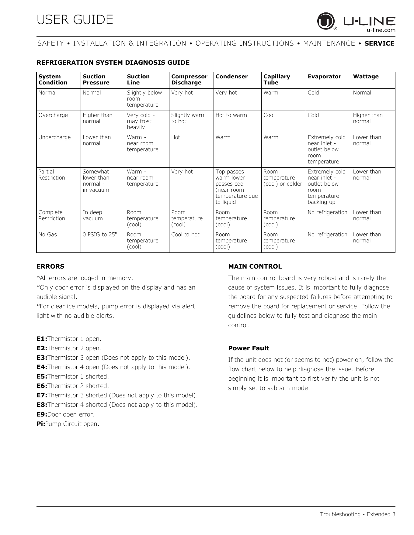
REFRIGERATION SYSTEM DIAGNOSIS GUIDE
ERRORS
*All errors are logged in memory.
*Only door error is displayed on the display and has an
audible signal.
*For clear ice models, pump error is displayed via alert
light with no audible alerts.
E1:Thermistor 1 open.
E2:Thermistor 2 open.
E3:Thermistor 3 open (Does not apply to this model).
E4:Thermistor 4 open (Does not apply to this model).
E5:Thermistor 1 shorted.
E6:Thermistor 2 shorted.
E7:Thermistor 3 shorted (Does not apply to this model).
E8:Thermistor 4 shorted (Does not apply to this model).
E9:Door open error.
Pi:Pump Circuit open.
MAIN CONTROL
The main control board is very robust and is rarely the
cause of system issues. It is important to fully diagnose
the board for any suspected failures before attempting to
remove the board for replacement or service. Follow the
guidelines below to fully test and diagnose the main
control.
Power Fault
If the unit does not (or seems to not) power on, follow the
flow chart below to help diagnose the issue. Before
beginning it is important to first verify the unit is not
simply set to sabbath mode.
System
Condition
Suction
Pressure
Suction
Line
Compressor
Discharge
Condenser Capillary
Tube
Evaporator Wattage
Normal Normal Slightly below
room
temperature
Very hot Very hot Warm Cold Normal
Overcharge Higher than
normal
Very cold -
may frost
heavily
Slightly warm
to hot
Hot to warm Cool Cold Higher than
normal
Undercharge Lower than
normal
Warm -
near room
temperature
Hot Warm Warm Extremely cold
near inlet -
outlet below
room
temperature
Lower than
normal
Partial
Restriction
Somewhat
lower than
normal -
in vacuum
Warm -
near room
temperature
Very hot Top passes
warm lower
passes cool
(near room
temperature due
to liquid
Room
temperature
(cool) or colder
Extremely cold
near inlet -
outlet below
room
temperature
backing up
Lower than
normal
Complete
Restriction
In deep
vacuum
Room
temperature
(cool)
Room
temperature
(cool)
Room
temperature
(cool)
Room
temperature
(cool)
No refrigeration Lower than
normal
No Gas 0 PSIG to 25" Room
temperature
(cool)
Cool to hot Room
temperature
(cool)
Room
temperature
(cool)
No refrigeration Lower than
normal
41
USER GUIDE
Troubleshooting - Extended 4
u-line.com
SAFETY • INSTALLATION & INTEGRATION • OPERATING INSTRUCTIONS • MAINTENANCE • SERVICE
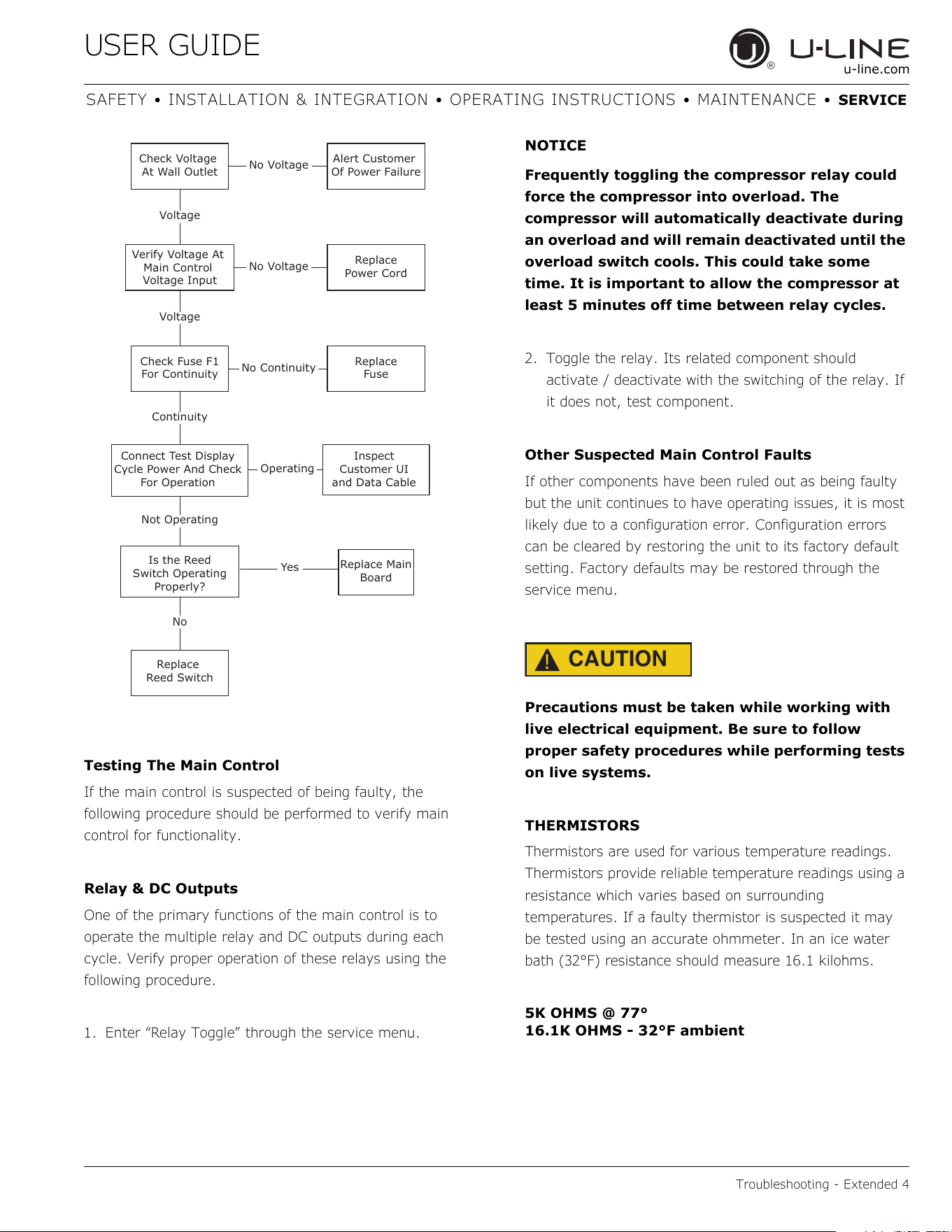
Testing The Main Control
If the main control is suspected of being faulty, the
following procedure should be performed to verify main
control for functionality.
Relay & DC Outputs
One of the primary functions of the main control is to
operate the multiple relay and DC outputs during each
cycle. Verify proper operation of these relays using the
following procedure.
1. Enter “Relay Toggle” through the service menu.
NOTICE
Frequently toggling the compressor relay could
force the compressor into overload. The
compressor will automatically deactivate during
an overload and will remain deactivated until the
overload switch cools. This could take some
time. It is important to allow the compressor at
least 5 minutes off time between relay cycles.
2. Toggle the relay. Its related component should
activate / deactivate with the switching of the relay. If
it does not, test component.
Other Suspected Main Control Faults
If other components have been ruled out as being faulty
but the unit continues to have operating issues, it is most
likely due to a configuration error. Configuration errors
can be cleared by restoring the unit to its factory default
setting. Factory defaults may be restored through the
service menu.
CAUTION
!
Precautions must be taken while working with
live electrical equipment. Be sure to follow
proper safety procedures while performing tests
on live systems.
THERMISTORS
Thermistors are used for various temperature readings.
Thermistors provide reliable temperature readings using a
resistance which varies based on surrounding
temperatures. If a faulty thermistor is suspected it may
be tested using an accurate ohmmeter. In an ice water
bath (32°F) resistance should measure 16.1 kilohms.
5K OHMS @ 77°
16.1K OHMS - 32°F ambient
Check Voltage
At Wall Outlet
Verify Voltage At
Main Control
Voltage Input
Check Fuse F1
For Continuity
Replace
Reed Switch
Replace Main
Board
Replace
Fuse
Replace
Power Cord
Alert Customer
Of Power Failure
Is the Reed
Switch Operating
Properly?
Inspect
Customer UI
and Data Cable
Connect Test Display
Cycle Power And Check
For Operation
No Voltage
No Voltage
Voltage
Continuity
Operating
Not Operating
No Continuity
No
Yes
Voltage
42
USER GUIDE
Troubleshooting - Extended 5
u-line.com
SAFETY • INSTALLATION & INTEGRATION • OPERATING INSTRUCTIONS • MAINTENANCE • SERVICE
THERMISTOR FAILURE
Always assure that all thermistor connections are clean
and dry. Whenever opening a thermistor connection be
sure to apply a fresh dab of die electric grease.
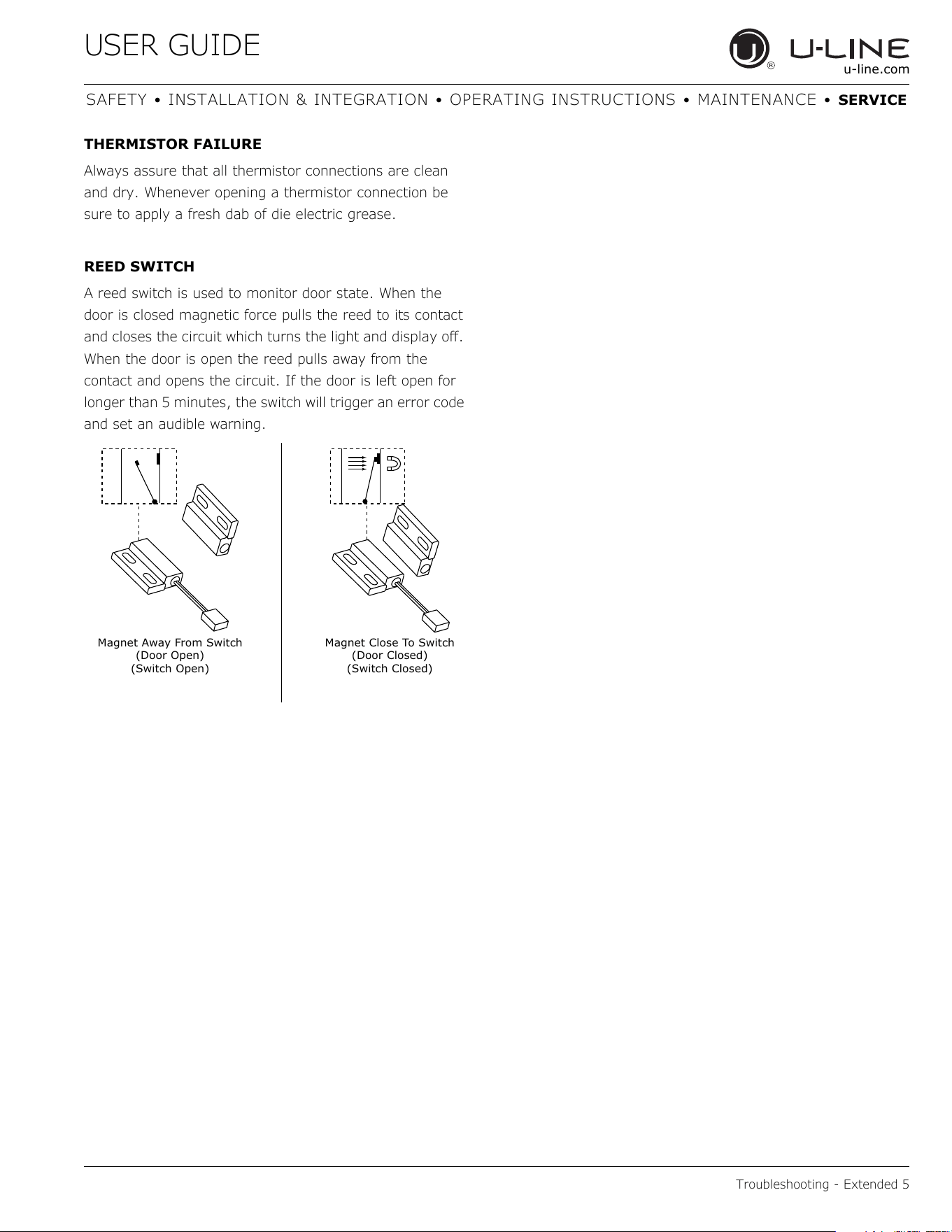
REED SWITCH
A reed switch is used to monitor door state. When the
door is closed magnetic force pulls the reed to its contact
and closes the circuit which turns the light and display off.
When the door is open the reed pulls away from the
contact and opens the circuit. If the door is left open for
longer than 5 minutes, the switch will trigger an error code
and set an audible warning.
Magnet Close To Switch
(Door Closed)
(Switch Closed)
Magnet Away From Switch
(Door Open)
(Switch Open)
43
USER GUIDE
Control Operation - Service 1
u-line.com
SAFETY • INSTALLATION & INTEGRATION • OPERATING INSTRUCTIONS • MAINTENANCE • SERVICE
Control Operation - Service
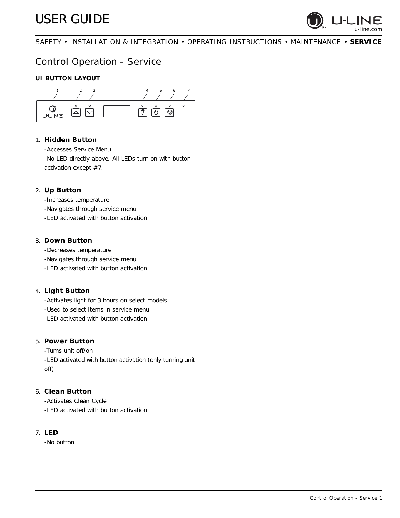
UI BUTTON LAYOUT
1. Hidden Button
-Accesses Service Menu
-No LED directly above. All LEDs turn on with button
activation except #7.
2.
Up Button
-Increases temperature
-Navigates through service menu
-LED activated with button activation.
3.
Down Button
-Decreases temperature
-Navigates through service menu
-LED activated with button activation
4.
Light Button
-Activates light for 3 hours on select models
-Used to select items in service menu
-LED activated with button activation
5.
Power Button
-Turns unit off/on
-LED activated with button activation (only turning unit
off)
6. Clean Button
-Activates Clean Cycle
-LED activated with button activation
7.
LED
-No button
123 4567
44
USER GUIDE
Control Operation - Service 2
u-line.com
SAFETY • INSTALLATION & INTEGRATION • OPERATING INSTRUCTIONS • MAINTENANCE • SERVICE
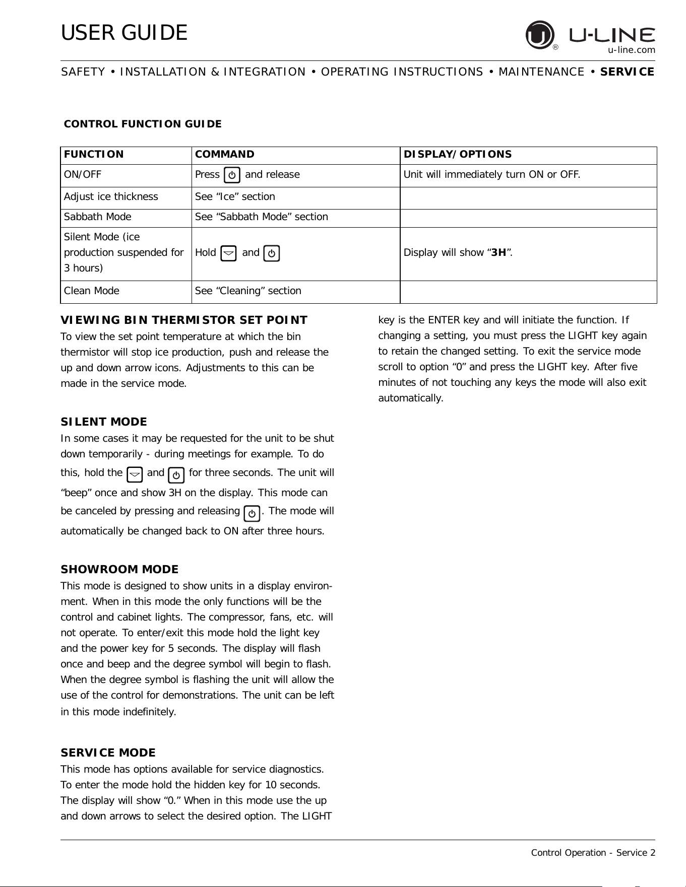
VIEWING BIN THERMISTOR SET POINT
To view the set point temperature at which the bin
thermistor will stop ice production, push and release the
up and down arrow icons. Adjustments to this can be
made in the service mode.
SILENT MODE
In some cases it may be requested for the unit to be shut
down temporarily - during meetings for example. To do
this, hold the and for three seconds. The unit will
“beep” once and show 3H on the display. This mode can
be canceled by pressing and releasing . The mode will
automatically be changed back to ON after three hours.
SHOWROOM MODE
This mode is designed to show units in a display environ-
ment. When in this mode the only functions will be the
control and cabinet lights. The compressor, fans, etc. will
not operate. To enter/exit this mode hold the light key
and the power key for 5 seconds. The display will flash
once and beep and the degree symbol will begin to flash.
When the degree symbol is flashing the unit will allow the
use of the control for demonstrations. The unit can be left
in this mode indefinitely.
SERVICE MODE
This mode has options available for service diagnostics.
To enter the mode hold the hidden key for 10 seconds.
The display will show “0.” When in this mode use the up
and down arrows to select the desired option. The LIGHT
key is the ENTER key and will initiate the function. If
changing a setting, you must press the LIGHT key again
to retain the changed setting. To exit the service mode
scroll to option “0” and press the LIGHT key. After five
minutes of not touching any keys the mode will also exit
automatically.
CONTROL FUNCTION GUIDE
FUNCTION COMMAND DISPLAY/OPTIONS
ON/OFF Press and release Unit will immediately turn ON or OFF.
Adjust ice thickness See “Ice” section
Sabbath Mode See “Sabbath Mode” section
Silent Mode (ice
production suspended for
3 hours)
Hold
and Display will show “3H”.
Clean Mode See “Cleaning” section
45
USER GUIDE
Control Operation - Service 3
u-line.com
SAFETY • INSTALLATION & INTEGRATION • OPERATING INSTRUCTIONS • MAINTENANCE • SERVICE
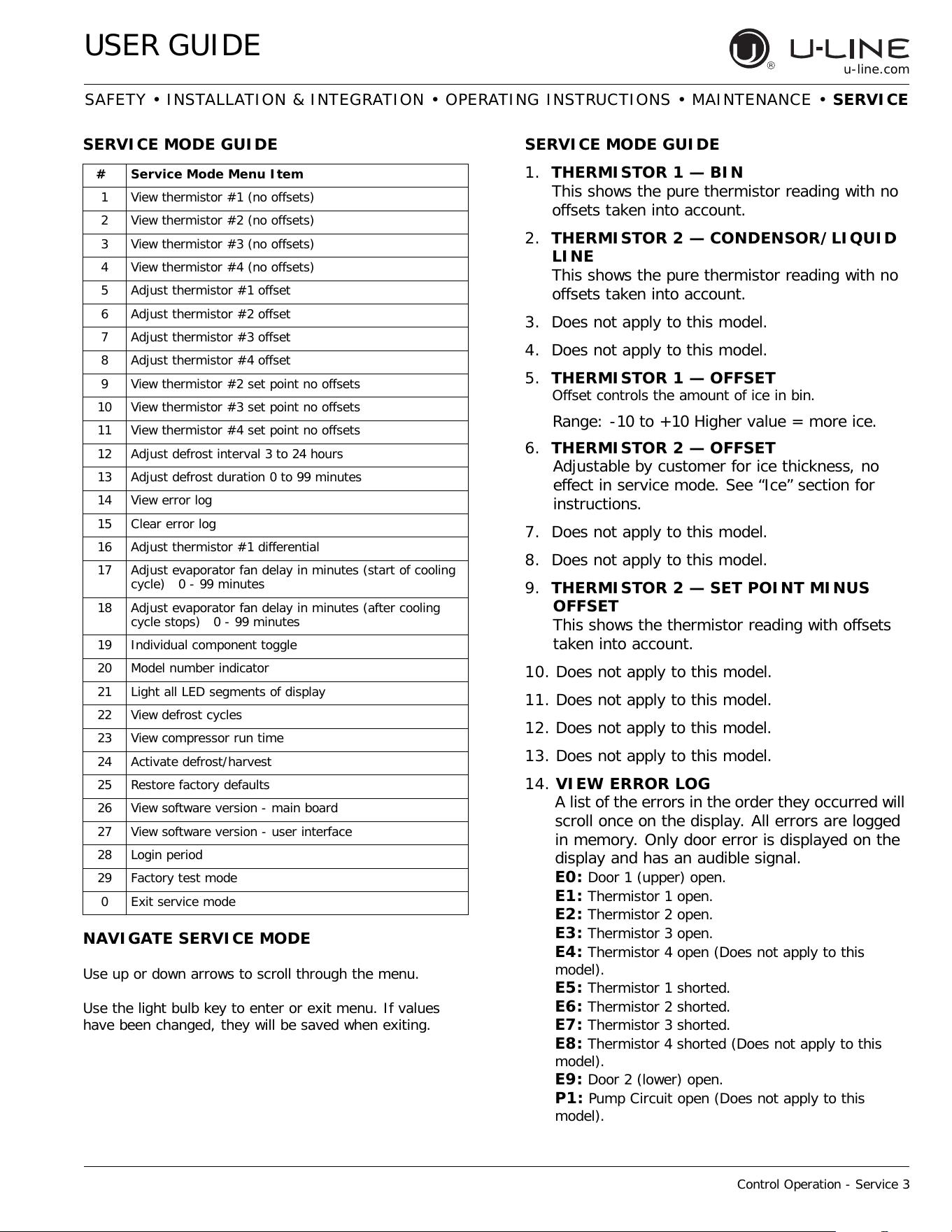
SERVICE MODE GUIDE
1. THERMISTOR 1 — BIN
This shows the pure thermistor reading with no
offsets taken into account.
2. THERMISTOR 2 — CONDENSOR/LIQUID
LINE
This shows the pure thermistor reading with no
offsets taken into account.
3. Does not apply to this model.
4. Does not apply to this model.
5. THERMISTOR 1 — OFFSET
Offset controls the amount of ice in bin.
Range: -10 to +10 Higher value = more ice.
6. THERMISTOR 2 — OFFSET
Adjustable by customer for ice thickness, no
effect in service mode. See “Ice” section for
instructions.
7. Does not apply to this model.
8. Does not apply to this model.
9. THERMISTOR 2 — SET POINT MINUS
OFFSET
This shows the thermistor reading with offsets
taken into account.
10. Does not apply to this model.
11. Does not apply to this model.
12. Does not apply to this model.
13. Does not apply to this model.
14. VIEW ERROR LOG
A list of the errors in the order they occurred will
scroll once on the display. All errors are logged
in memory. Only door error is displayed on the
display and has an audible signal.
E0:
Door 1 (upper) open.
E1: Thermistor 1 open.
E2: Thermistor 2 open.
E3: Thermistor 3 open.
E4: Thermistor 4 open (Does not apply to this
model).
E5: Thermistor 1 shorted.
E6: Thermistor 2 shorted.
E7: Thermistor 3 shorted.
E8: Thermistor 4 shorted (Does not apply to this
model).
E9: Door 2 (lower) open.
P1: Pump Circuit open (Does not apply to this
model).
# Service Mode Menu Item
1 View thermistor #1 (no offsets)
2 View thermistor #2 (no offsets)
3 View thermistor #3 (no offsets)
4 View thermistor #4 (no offsets)
5 Adjust thermistor #1 offset
6 Adjust thermistor #2 offset
7 Adjust thermistor #3 offset
8 Adjust thermistor #4 offset
9 View thermistor #2 set point no offsets
10 View thermistor #3 set point no offsets
11 View thermistor #4 set point no offsets
12 Adjust defrost interval 3 to 24 hours
13 Adjust defrost duration 0 to 99 minutes
14 View error log
15 Clear error log
16 Adjust thermistor #1 differential
17 Adjust evaporator fan delay in minutes (start of cooling
cycle) 0 - 99 minutes
18 Adjust evaporator fan delay in minutes (after cooling
cycle stops) 0 - 99 minutes
19 Individual component toggle
20 Model number indicator
21 Light all LED segments of display
22 View defrost cycles
23 View compressor run time
24 Activate defrost/harvest
25 Restore factory defaults
26 View software version - main board
27 View software version - user interface
28 Login period
29 Factory test mode
0Exit service mode
NAVIGATE SERVICE MODE
Use up or down arrows to scroll through the menu.
Use the light bulb key to enter or exit menu. If values
have been changed, they will be saved when exiting.
SERVICE MODE GUIDE
46
USER GUIDE
Control Operation - Service 4
u-line.com
SAFETY • INSTALLATION & INTEGRATION • OPERATING INSTRUCTIONS • MAINTENANCE • SERVICE
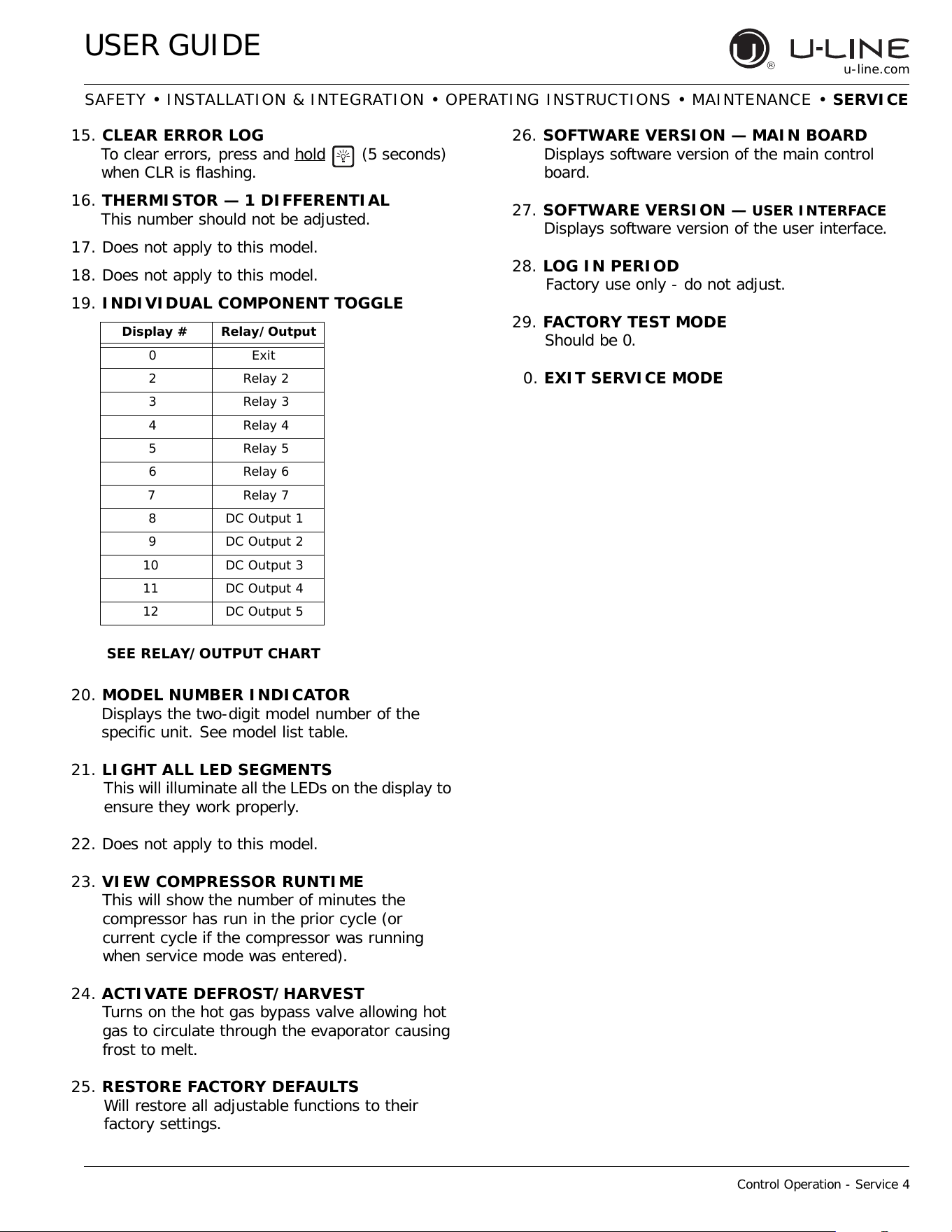
15. CLEAR ERROR LOG
To clear errors, press and hold
(5 seconds)
when CLR is flashing.
16. THERMISTOR — 1 DIFFERENTIAL
This number should not be adjusted.
17. Does not apply to this model.
18. Does not apply to this model.
19. INDIVIDUAL COMPONENT TOGGLE
20. MODEL NUMBER INDICATOR
Displays the two-digit model number of the
specific unit. See model list table.
21. LIGHT ALL LED SEGMENTS
This will illuminate all the LEDs on the display to
ensure they work properly.
22. Does not apply to this model.
23. VIEW COMPRESSOR RUNTIME
This will show the number of minutes the
compressor has run in the prior cycle (or
current cycle if the compressor was running
when service mode was entered).
24. ACTIVATE DEFROST/HARVEST
Turns on the hot gas bypass valve allowing hot
gas to circulate through the evaporator causing
frost to melt.
25. RESTORE FACTORY DEFAULTS
Will restore all adjustable functions to their
factory settings.
26. SOFTWARE VERSION — MAIN BOARD
Displays software version of the main control
board.
27. SOFTWARE VERSION —
USER INTERFACE
Displays software version of the user interface.
28. LOG IN PERIOD
Factory use only - do not adjust.
29. FACTORY TEST MODE
Should be 0.
0. EXIT SERVICE MODE
Display # Relay/Output
0 Exit
2 Relay 2
3 Relay 3
4 Relay 4
5 Relay 5
6 Relay 6
7 Relay 7
8 DC Output 1
9 DC Output 2
10 DC Output 3
11 DC Output 4
12 DC Output 5
SEE RELAY/OUTPUT CHART
47
USER GUIDE
Control Operation - Service 5
u-line.com
SAFETY • INSTALLATION & INTEGRATION • OPERATING INSTRUCTIONS • MAINTENANCE • SERVICE
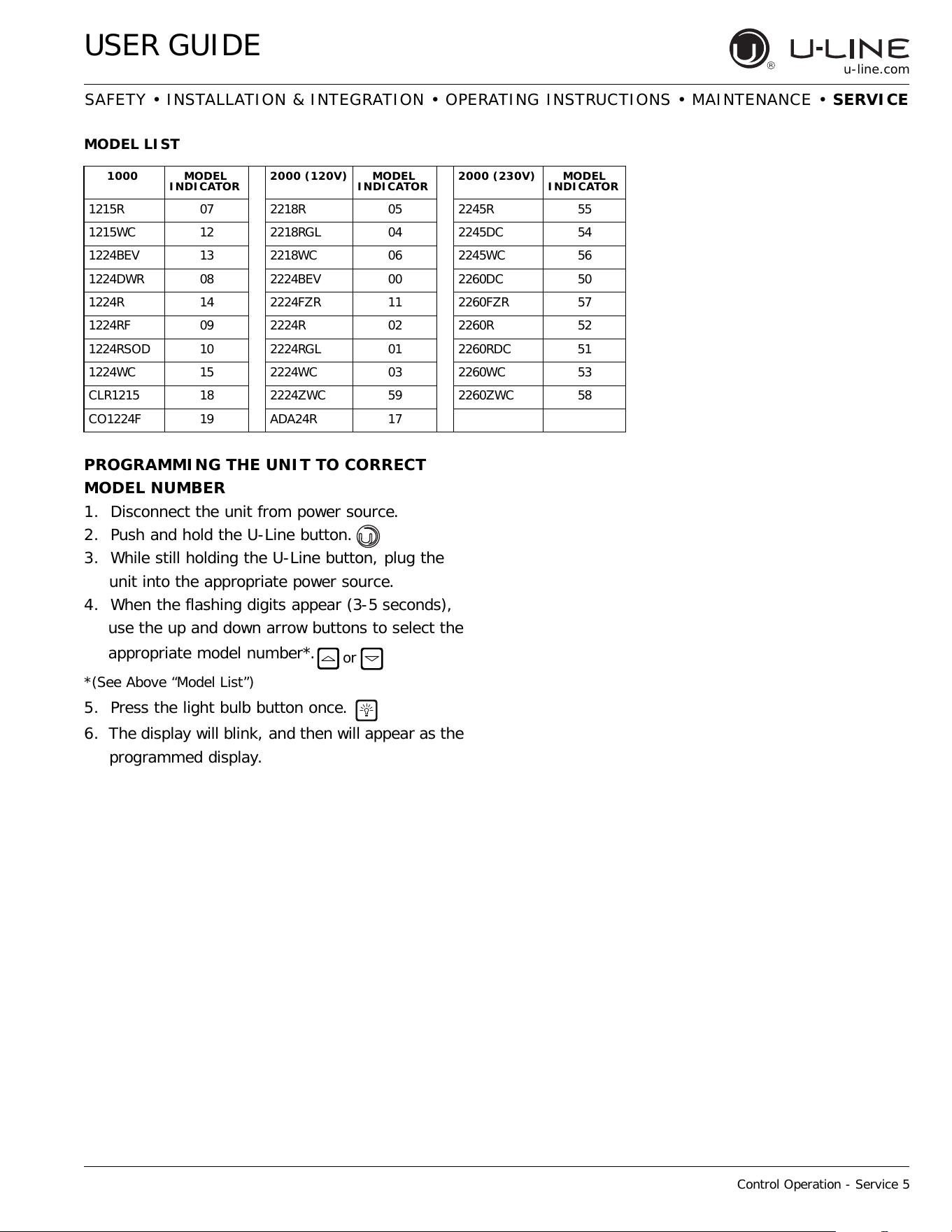
MODEL LIST
PROGRAMMING THE UNIT TO CORRECT
MODEL NUMBER
1. Disconnect the unit from power source.
2. Push and hold the U-Line button.
3. While still holding the U-Line button, plug the
unit into the appropriate power source.
4. When the flashing digits appear (3-5 seconds),
use the up and down arrow buttons to select the
appropriate model number*.
*(See Above “Model List”)
5. Press the light bulb button once.
6. The display will blink, and then will appear as the
programmed display.
1000 MODEL
INDICATOR
2000 (120V) MODEL
INDICATOR
2000 (230V) MODEL
INDICATOR
1215R 07 2218R 05 2245R 55
1215WC 12 2218RGL 04 2245DC 54
1224BEV 13 2218WC 06 2245WC 56
1224DWR 08 2224BEV 00 2260DC 50
1224R 14 2224FZR 11 2260FZR 57
1224RF 09 2224R 02 2260R 52
1224RSOD 10 2224RGL 01 2260RDC 51
1224WC 15 2224WC 03 2260WC 53
CLR1215 18 2224ZWC 59 2260ZWC 58
CO1224F 19 ADA24R 17
or
48
USER GUIDE
Control Operation - Service 6
u-line.com
SAFETY • INSTALLATION & INTEGRATION • OPERATING INSTRUCTIONS • MAINTENANCE • SERVICE
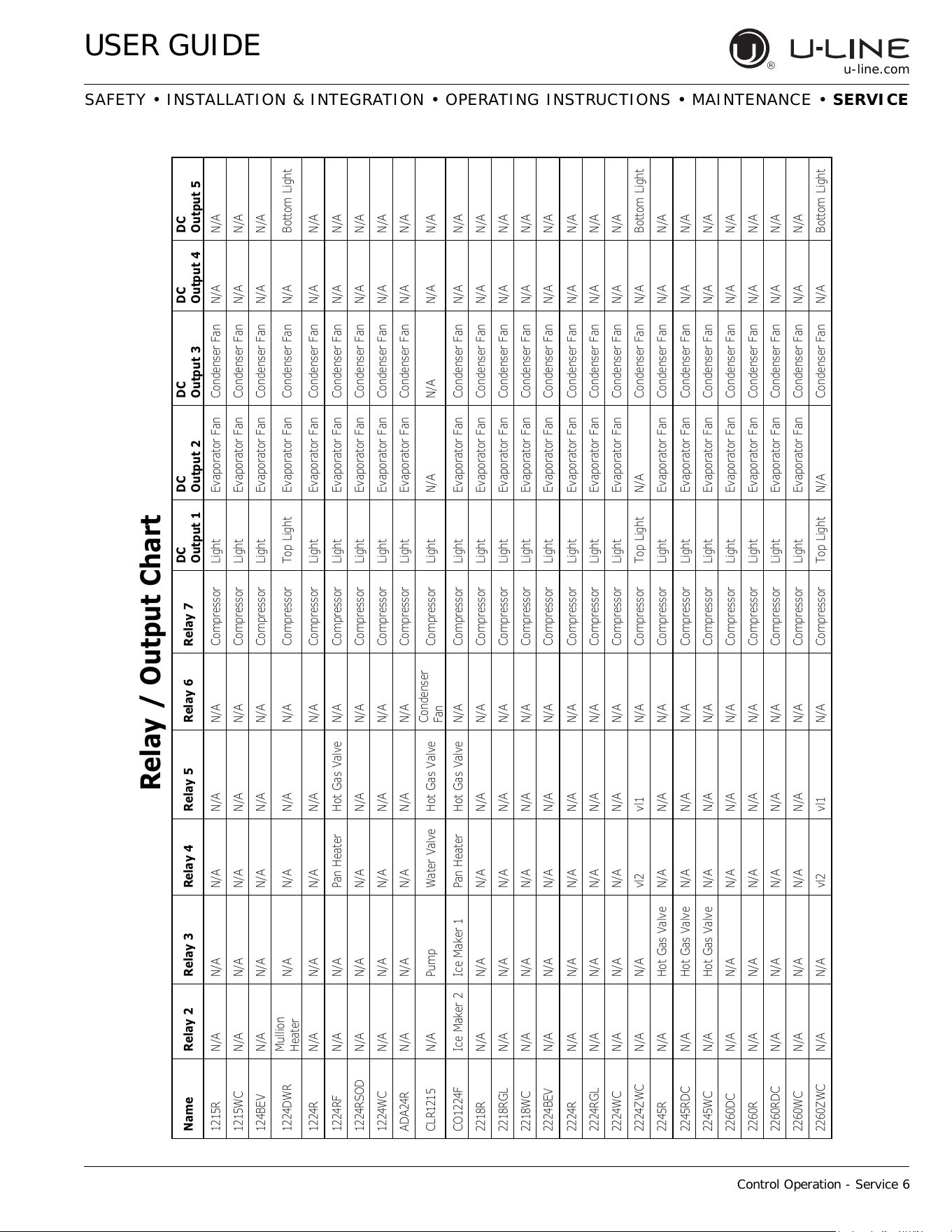
Name Relay 2 Relay 3 Relay 4 Relay 5 Relay 6 Relay 7
DC
Out
p
ut 1
DC
Out
p
ut 2
DC
Out
p
ut 3
DC
Out
p
ut 4
DC
Out
p
ut 5
1215R N/A N/A N/A N/A N/A Compressor Light Evaporator Fan Condenser Fan N/A N/A
1215WC N/A N/A N/A N/A N/A Compressor Light Evaporator Fan Condenser Fan N/A N/A
124BEV N/A N/A N/A N/A N/A Compressor Light Evaporator Fan Condenser Fan N/A N/A
1224DWR
Mullion
Heater
N/A N/A N/A N/A Compressor Top Light Evaporator Fan Condenser Fan N/A Bottom Light
1224R N/A N/A N/A N/A N/A Compressor Light Evaporator Fan Condenser Fan N/A N/A
1224RF N/A N/A Pan Heater Hot Gas Valve N/A Compressor Light Evaporator Fan Condenser Fan N/A N/A
1224RSOD N/A N/A N/A N/A N/A Compressor Light Evaporator Fan Condenser Fan N/A N/A
1224WC N/A N/A N/A N/A N/A Compressor Light Evaporator Fan Condenser Fan N/A N/A
ADA24R N/A N/A N/A N/A N/A Compressor Light Evaporator Fan Condenser Fan N/A N/A
CLR1215 N/A Pump Water Valve Hot Gas Valve
Condenser
Fan
Compressor Light N/A N/A N/A N/A
CO1224F Ice Maker 2 Ice Maker 1 Pan Heater Hot Gas Valve N/A Compressor Light Evaporator Fan Condenser Fan N/A N/A
2218R N/A N/A N/A N/A N/A Compressor Light Evaporator Fan Condenser Fan N/A N/A
2218RGL N/A N/A N/A N/A N/A Compressor Light Evaporator Fan Condenser Fan N/A N/A
2218WC N/A N/A N/A N/A N/A Compressor Light Evaporator Fan Condenser Fan N/A N/A
2224BEV N/A N/A N/A N/A N/A Compressor Light Evaporator Fan Condenser Fan N/A N/A
2224R N/A N/A N/A N/A N/A Compressor Light Evaporator Fan Condenser Fan N/A N/A
2224RGL N/A N/A N/A N/A N/A Compressor Light Evaporator Fan Condenser Fan N/A N/A
2224WC N/A N/A N/A N/A N/A Compressor Light Evaporator Fan Condenser Fan N/A N/A
2224ZWC N/A N/A vl2 vl1 N/A Compressor Top Light N/A Condenser Fan N/A Bottom Light
2245R N/A Hot Gas Valve N/A N/A N/A Compressor Light Evaporator Fan Condenser Fan N/A N/A
2245RDC N/A Hot Gas Valve N/A N/A N/A Compressor Light Evaporator Fan Condenser Fan N/A N/A
2245WC N/A Hot Gas Valve N/A N/A N/A Compressor Light Evaporator Fan Condenser Fan N/A N/A
2260DC N/A N/A N/A N/A N/A Compressor Light Evaporator Fan Condenser Fan N/A N/A
2260R N/A N/A N/A N/A N/A Compressor Light Evaporator Fan Condenser Fan N/A N/A
2260RDC N/A N/A N/A N/A N/A Compressor Light Evaporator Fan Condenser Fan N/A N/A
2260WC N/A N/A N/A N/A N/A Compressor Light Evaporator Fan Condenser Fan N/A N/A
2260ZWC N/A N/A vl2 vl1 N/A Compressor Top Light N/A Condenser Fan N/A Bottom Light
5HOD\2XWSXW&KDUW
49
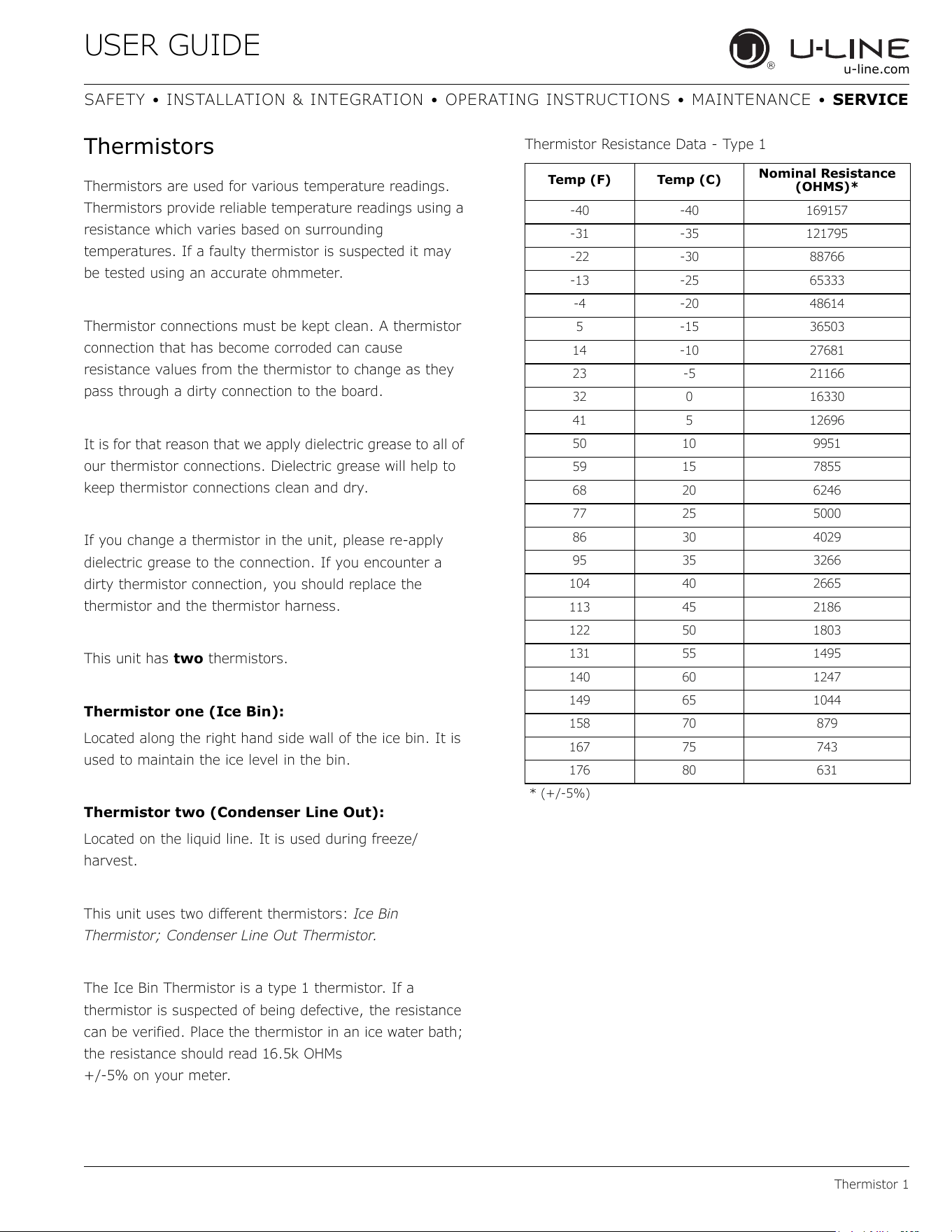
USER GUIDE
Thermistor 1
u-line.com
SAFETY • INSTALLATION & INTEGRATION • OPERATING INSTRUCTIONS • MAINTENANCE • SERVICE
Thermistors
Thermistors are used for various temperature readings.
Thermistors provide reliable temperature readings using a
resistance which varies based on surrounding
temperatures. If a faulty thermistor is suspected it may
be tested using an accurate ohmmeter.
Thermistor connections must be kept clean. A thermistor
connection that has become corroded can cause
resistance values from the thermistor to change as they
pass through a dirty connection to the board.
It is for that reason that we apply dielectric grease to all of
our thermistor connections. Dielectric grease will help to
keep thermistor connections clean and dry.
If you change a thermistor in the unit, please re-apply
dielectric grease to the connection. If you encounter a
dirty thermistor connection, you should replace the
thermistor and the thermistor harness.
This unit has two thermistors.
Thermistor one (Ice Bin):
Located along the right hand side wall of the ice bin. It is
used to maintain the ice level in the bin.
Thermistor two (Condenser Line Out):
Located on the liquid line. It is used during freeze/
harvest.
This unit uses two different thermistors: Ice Bin
Thermistor; Condenser Line Out Thermistor.
The Ice Bin Thermistor is a type 1 thermistor. If a
thermistor is suspected of being defective, the resistance
can be verified. Place the thermistor in an ice water bath;
the resistance should read 16.5k OHMs
+/-5% on your meter.
Thermistor Resistance Data - Type 1
Temp (F) Temp (C)
Nominal Resistance
(OHMS)*
-40 -40 169157
-31 -35 121795
-22 -30 88766
-13 -25 65333
-4 -20 48614
5-15 36503
14 -10 27681
23 -5 21166
32 0 16330
41 5 12696
50 10 9951
59 15 7855
68 20 6246
77 25 5000
86 30 4029
95 35 3266
104 40 2665
113 45 2186
122 50 1803
131 55 1495
140 60 1247
149 65 1044
158 70 879
167 75 743
176 80 631
* (+/-5%)
50
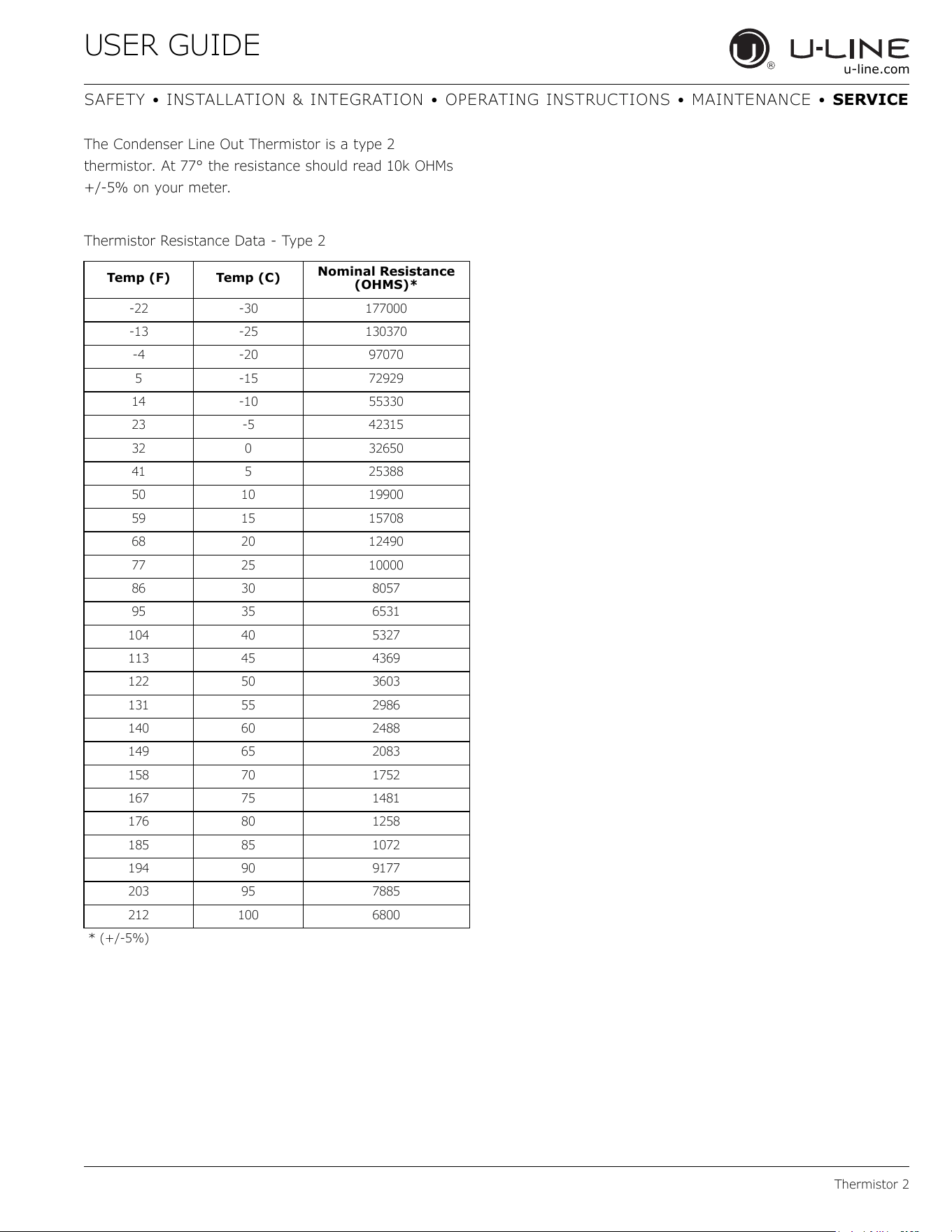
USER GUIDE
Thermistor 2
u-line.com
SAFETY • INSTALLATION & INTEGRATION • OPERATING INSTRUCTIONS • MAINTENANCE • SERVICE
The Condenser Line Out Thermistor is a type 2
thermistor. At 77° the resistance should read 10k OHMs
+/-5% on your meter.
Thermistor Resistance Data - Type 2
Temp (F) Temp (C)
Nominal Resistance
(OHMS)*
-22 -30 177000
-13 -25 130370
-4 -20 97070
5 -15 72929
14 -10 55330
23 -5 42315
32 0 32650
41 5 25388
50 10 19900
59 15 15708
68 20 12490
77 25 10000
86 30 8057
95 35 6531
104 40 5327
113 45 4369
122 50 3603
131 55 2986
140 60 2488
149 65 2083
158 70 1752
167 75 1481
176 80 1258
185 85 1072
194 90 9177
203 95 7885
212 100 6800
* (+/-5%)
51
USER GUIDE
Defrost 1
u-line.com
SAFETY • INSTALLATION & INTEGRATION • OPERATING INSTRUCTIONS • MAINTENANCE • SERVICE
Defrost
These models have no defrost options.
52
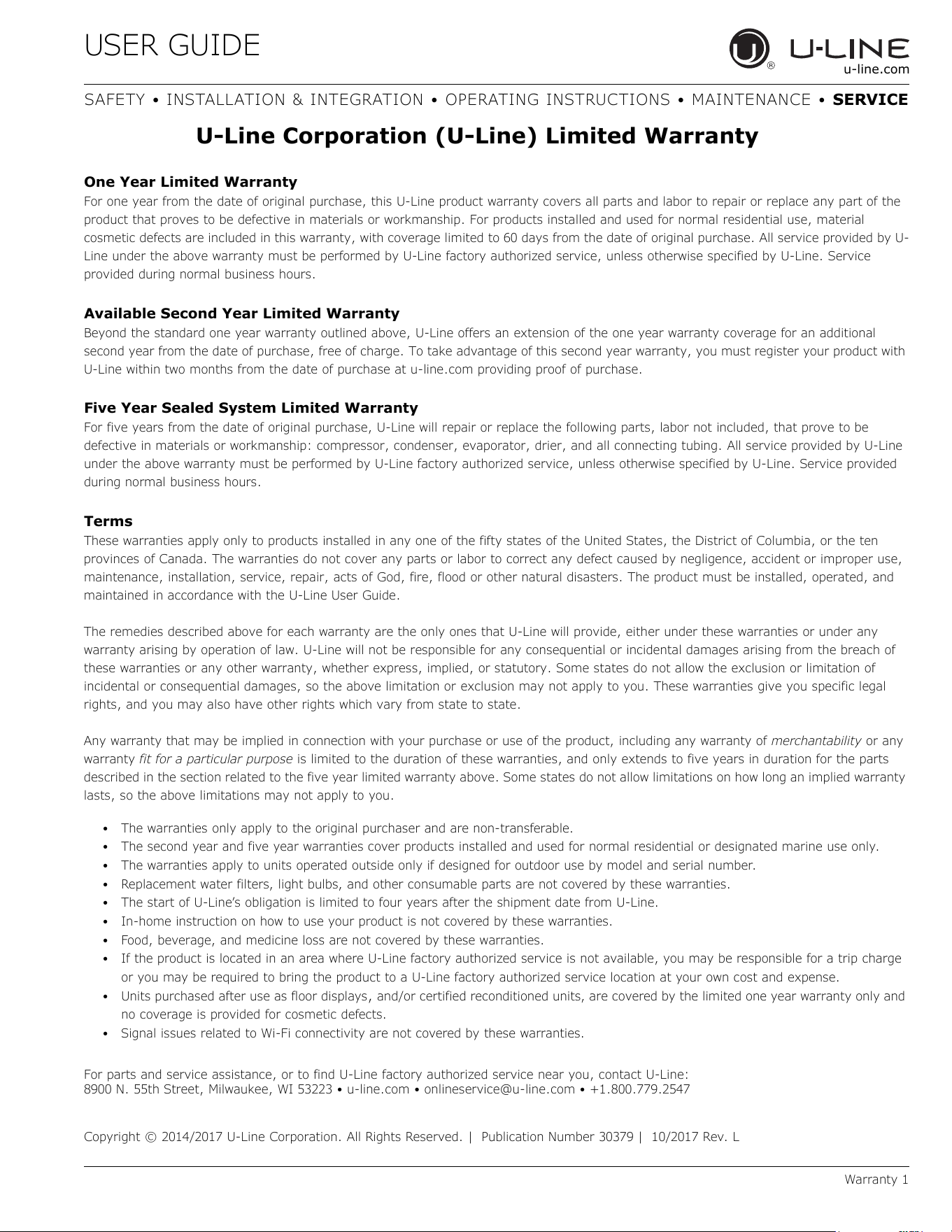
USER GUIDE
u-line.com
SAFETY • INSTALLATION & INTEGRATION • OPERATING INSTRUCTIONS • MAINTENANCE • SERVICE
U-Line Corporation (U-Line) Limited Warranty
One Year Limited Warranty
For one year from the date of original purchase, this U-Line product warranty covers all parts and labor to repair or replace any part of the
product that proves to be defective in materials or workmanship. For products installed and used for normal residential use, material
cosmetic defects are included in this warranty, with coverage limited to 60 days from the date of original purchase. All service provided by U-
Line under the above warranty must be performed by U-Line factory authorized service, unless otherwise specified by U-Line. Service
provided during normal business hours.
Available Second Year Limited Warranty
Beyond the standard one year warranty outlined above, U-Line offers an extension of the one year warranty coverage for an additional
second year from the date of purchase, free of charge. To take advantage of this second year warranty, you must register your product with
U-Line within two months from the date of purchase at u-line.com providing proof of purchase.
Five Year Sealed System Limited Warranty
For five years from the date of original purchase, U-Line will repair or replace the following parts, labor not included, that prove to be
defective in materials or workmanship: compressor, condenser, evaporator, drier, and all connecting tubing. All service provided by U-Line
under the above warranty must be performed by U-Line factory authorized service, unless otherwise specified by U-Line. Service provided
during normal business hours.
Terms
These warranties apply only to products installed in any one of the fifty states of the United States, the District of Columbia, or the ten
provinces of Canada. The warranties do not cover any parts or labor to correct any defect caused by negligence, accident or improper use,
maintenance, installation, service, repair, acts of God, fire, flood or other natural disasters. The product must be installed, operated, and
maintained in accordance with the U-Line User Guide.
The remedies described above for each warranty are the only ones that U-Line will provide, either under these warranties or under any
warranty arising by operation of law. U-Line will not be responsible for any consequential or incidental damages arising from the breach of
these warranties or any other warranty, whether express, implied, or statutory. Some states do not allow the exclusion or limitation of
incidental or consequential damages, so the above limitation or exclusion may not apply to you. These warranties give you specific legal
rights, and you may also have other rights which vary from state to state.
Any warranty that may be implied in connection with your purchase or use of the product, including any warranty of merchantability or any
warranty fit for a particular purpose is limited to the duration of these warranties, and only extends to five years in duration for the parts
described in the section related to the five year limited warranty above. Some states do not allow limitations on how long an implied warranty
lasts, so the above limitations may not apply to you.
• The warranties only apply to the original purchaser and are non-transferable.
• The second year and five year warranties cover products installed and used for normal residential or designated marine use only.
• The warranties apply to units operated outside only if designed for outdoor use by model and serial number.
• Replacement water filters, light bulbs, and other consumable parts are not covered by these warranties.
• The start of U-Line’s obligation is limited to four years after the shipment date from U-Line.
• In-home instruction on how to use your product is not covered by these warranties.
• Food, beverage, and medicine loss are not covered by these warranties.
• If the product is located in an area where U-Line factory authorized service is not available, you may be responsible for a trip charge
or you may be required to bring the product to a U-Line factory authorized service location at your own cost and expense.
• Units purchased after use as floor displays
, and/or certified reconditioned units, are covered by the limited one year warranty only and
no coverage is provided for cosmetic defects.
• Signal issues related to Wi-Fi connectivity are not covered by these warranties.
For parts and service assistance, or to find U-Line factory authorized service near you, contact U-Line:
8900 N. 55th Street, Milwaukee, WI 53223 • u-line.com • onlineservice@u-line.com • +1.800.779.2547
Copyright © 2014/2017 U-Line Corporation. All Rights Reserved. | Publication Number 30379 | 10/2017 Rev. L
Warranty 1
53