USER GUIDE & SERVICE MANUAL
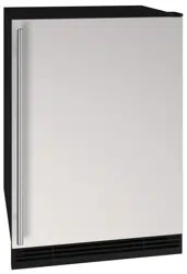
Model: UHRI124-WS01A
USER GUIDE & SERVICE MANUAL
Table of Contents
Click on any section below to jump directly there
Intro
Safety
Safety and Warning
Disposal And Recycling
Installation
Environmental Requirements
Electrical
Cutout & Product Dimensions
Side by Side Installation
Water Hookup
Anti-Tip Bracket
General Installation
Grille Installation
Door Swing
Door Adjust
Interior Adjustments
Maintenance
Free Standing Kit
Cleaning
Cleaning Condenser
Extended Non-Use
Operating Instructions
First Use
Control Operation
Ice
Airflow and Product Loading
Service
Troubleshooting
Wire Diagram
Product Liability
Parts
R600a Specifications
System Diagnosis Guide
Compressor Specifications
Troubleshooting Extended
Control Operation - Service
Warranty
USER GUIDE
u-line.com
Introduction
WELCOME TO U-LINE
Congratulations on your U-Line purchase! Our products are focused on functionality, style, and inspired innovations — paying
close attention to even the smallest details. Applications include residential, outdoor, ADA height compliant, marine, and
commercial. Product categories include Beverage Centers, Wine Refrigerators, Ice Machines, Refrigerators, Freezers, and
Dispensers. Our advanced refrigeration systems, large and exible capacities, and clean integrated look are what makes our
products Built-In to Stand Out
®
. Since 2014, U-Line has been part of the Middleby family of brands.
U-Line — RIGHT PRODUCT. RIGHT PLACE. RIGHT TEMPERATURE.
®
PRODUCT INFORMATION
Looking for additional information on your product? User Guides, Spec Sheets, CAD Drawings, and Product Warranty
information are available digitally on u-line.com.
PROPERTY DAMAGE / INJURY CONCERNS
In the unlikely event property damage or personal injury is suspected related to a U-Line product, please take the following
steps:
1. U-Line Customer Care must be contacted immediately at +1.414.354.0300.
2. Service or repairs performed on the unit without prior written approval from U-Line is not permitted. If the unit has been
altered or repaired in the eld without prior written approval from U-Line, claims will not be eligible.
GENERAL INQUIRIES
U-Line Corporation
8900 N. 55th Street
Milwaukee, Wisconsin 53223 USA
Monday - Friday 8:00 am to 4:30 pm CST
T: +1.414.354.0300
Email: sales@u-line.com
u-line.com
CONNECT WITH US AT MIDDLEBY REFRIGERATION
SERVICE & PARTS ASSISTANCE
Monday - Friday 8:00 am to 4:30 pm CST
T: +1.414.354.0300
Service Email: onlineservice@u-line.com
Parts Email: onlineparts@u-line.com
3
USER GUIDE
Safety and Warning
Safety and Warning
NOTICE
Please read all instructions before installing,
operating, or servicing the appliance.
Use this appliance for its intended purpose only and follow
these general precautions with those listed throughout this
guide:
SAFETY ALERT DEFINITIONS
Throughout this guide are safety items labeled with a
Danger, Warning, or Caution based on the risk type:
Danger means that failure to follow this safety
statement will result in severe personal injury or
death.
Warning means that failure to follow this safety
statement could result in serious personal injury
or death.
Caution means that failure to follow this safety
statement may result in minor or moderate
personal injury, property, or equipment damage.
This unit contains R600a (Isobutane) which is a
ammable hydrocarbon. It is safe for regular
use. Do not use sharp objects to expedite
defrosting. Do not service without consulting the
“R600a specications” section included in the
User Guide. Do not damage the refrigerant
circuit.
Service must be done by factory authorized
service personnel. Any parts shall be replaced
with like components. Failure to comply could
increase the risk of possible ignition due to
incorrect parts or improper service.
CALIFORNIA PROPOSITION 65
This product contains chemicals known to the
state of California to cause cancer and birth
defects or other reproductive harm.
www.P65warnings.CA.gov
This equipment is to be installed with adequate
backow protection to comply with applicable
federal, state and local codes.
DANGER
!
DANGER
!
WARNING
!
CAUTION
!
CAUTION
!
WARNING
!
4
USER GUIDE
Disposal and Recycling
Disposal and Recycling
RISK OF CHILD ENTRAPMENT. Before you throw
away your old refrigerator or freezer, take o
the doors and leave shelves in place so children
may not easily climb inside.
If the unit is being removed from service for disposal,
check and obey all federal, state, and local regulations
regarding the disposal and recycling of refrigeration
appliances, and follow these steps completely:
1. Remove all consumable contents from the unit.
2. Unplug the electrical cord from its socket.
3. Remove the door(s)/drawer(s).
DANGER
!
5
USER GUIDE
Environmental Requirements
Environmental Requirements
This model is intended for indoor/interior applications only
and is not to be used in installations that are open/
exposed to natural elements.
This unit is designed to operate between 50°F (10°C) and
100°F (38°C). Higher ambient temperatures may reduce
the unit’s ability to reach low temperatures and/or reduce
ice production on applicable models.
For best performance, keep the unit out of direct sunlight
and away from heat generating equipment.
In climates where high humidity and dew points are
present, condensation may appear on outside surfaces.
This is considered normal. The condensation will
evaporate when the humidity drops.
CAUTION
!
Damages caused by ambient temperatures of
40°F (4°C) or below are not covered by the
warranty.
6
USER GUIDE
Electrical
Electrical
WARNING
!
SHOCK HAZARD — Electrical Grounding
Required. Never attempt to repair or perform
maintenance on the unit until the electricity has
been disconnected.
Never remove the round grounding prong from
the plug and never use a two-prong grounding
adapter.
Altering, cutting or removing power cord,
removing power plug, or direct wiring can cause
serious injury, fire, loss of property and/or life,
and will void the warranty.
Never use an extension cord to connect power to
the unit.
Always keep your working area dry.
NOTICE
Electrical installation must observe all state and
local codes. This unit requires connection to a
grounded (three-prong), polarized receptacle
that has been placed by a qualified electrician.
The unit requires a grounded and polarized 115 VAC,
60 Hz, 15A power supply (normal household current). An
individual, properly grounded branch circuit or circuit
breaker is recommended. A GFCI (ground fault circuit
interrupter) is usually not required for fixed location
appliances and is not recommended for your unit because
it could be prone to nuisance tripping. However, be sure
to consult your local codes.
See CUTOUT & PRODUCT DIMENSIONS for recommended
receptacle location.
7
USER GUIDE
Cutout & Product Dimensions
Cutout & Product Dimensions
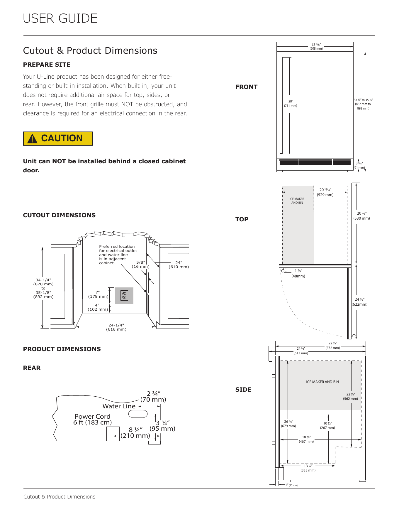
PREPARE SITE
Your U-Line product has been designed for either free-
standing or built-in installation. When built-in, your unit
does not require additional air space for top, sides, or
rear. However, the front grille must NOT be obstructed, and
clearance is required for an electrical connection in the rear.
CAUTION
!
Unit can NOT be installed behind a closed cabinet
door.
CUTOUT DIMENSIONS
PRODUCT DIMENSIONS
REAR
FRONT
TOP
SIDE
ICE MAKER AND BIN
22 1⁄8”
(562 mm)
13 1⁄8”
(333 mm)
18 3⁄8”
(467 mm)
10
½
”
(267 mm)
26 ¾”
(679 mm)
22 ½”
(572 mm)
24 3⁄8”
(613 mm)
1
”
(25 mm)
4"
(102 mm)
7"
(178 mm)
24"
(610 mm)
24-1/4"
(616 mm)
34-1/4"
(870 mm)
to
35-1/8"
(892 mm)
Preferred location
for electrical outlet
and water line
is in adjacent
cabinet.
5/8"
(16 mm)
Power Cord
6 ft (183 cm)
Water Line
2 ¾”
(70 mm)
3 ¾”
(95 mm)
8 ¼”
(210 mm)
23 15⁄16”
(608 mm)
3 9⁄16”
(91 mm)
34 1⁄8” to 35 1⁄8”
(867 mm to
892 mm)
28”
(711 mm)
ICE MAKER
AND BIN
1 7⁄8”
(48mm)
20 13⁄16”
(529 mm)
24 ½”
(622mm)
20 7⁄8”
(530 mm)
8
USER GUIDE
Side-by-Side Installation
Side-by-Side Installation
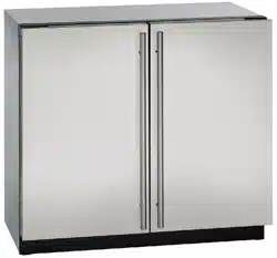
Two units may be installed side-by-side.
Cutout width for a side-by-side installation is the cutout
dimension of a single unit times two.
No trim kit is required. However, 1/4" (6 mm) of space
needs to be maintained between the units to ensure
unobstructed door swing.
Units must operate from separate, properly grounded
electrical receptacles placed according to each unit’s
electrical specifications requirements.
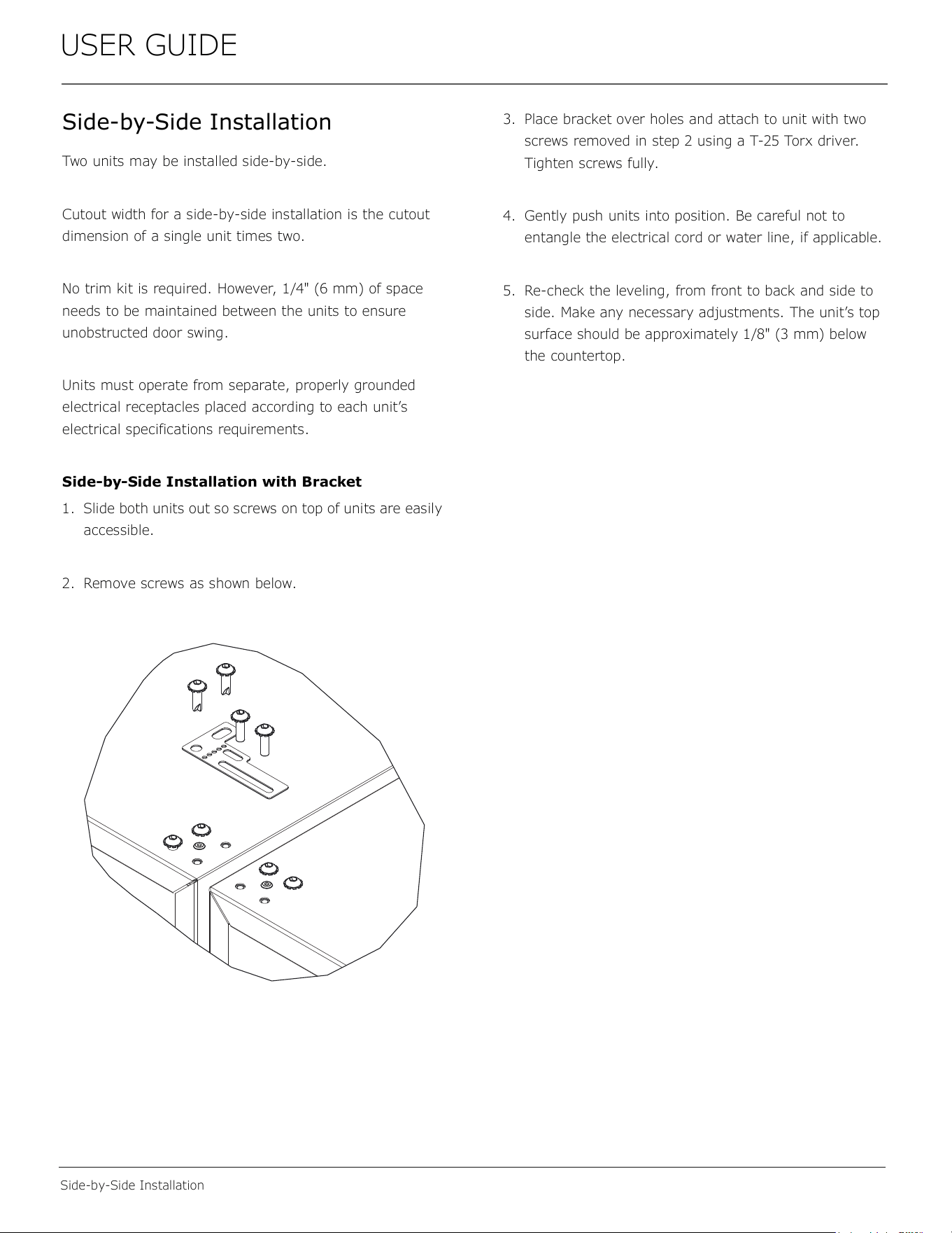
Side-by-Side Installation with Bracket
1. Slide both units out so screws on top of units are easily
accessible.
2. Remove screws as shown below.
3. Place bracket over holes and attach to unit with two
screws removed in step 2 using a T-25 Torx driver.
Tighten screws fully.
4. Gently push units into position. Be careful not to
entangle the electrical cord or water line, if applicable.
5. Re-check the leveling, from front to back and side to
side. Make any necessary adjustments. The unit’s top
surface should be approximately 1/8" (3 mm) below
the countertop.
9
USER GUIDE
Water Hookup
Water Hookup
PREPARE PLUMBING
The water valve uses a standard 1/4" (6.35 mm)
compression fitting. U-Line recommends using accessory
water hook up kit – part # ULAWATERHOOKUP. The kit
includes a 10' (3 m) braided flexible water supply line and
a brass hose fitting.
CAUTION
!
Plumbing installation must observe all state and
local codes. All water and drain connections
MUST BE made by a licensed/qualified plumbing
contractor. Failure to follow recommendations
and instructions may result in damage and/or
harm.
Water Supply Connection
When connecting the water supply, please note the
following:
• Before installing the unit and connecting to the cold
water supply, review the local plumbing codes.
• The water pressure should be between 20 and 120 psi
(138 and 827 kPa).
• The water line MUST have a shut-off valve in the
supply line.
• The water line should be looped into 2 coils. This will
allow the unit to be removed for cleaning and servicing.
Make certain that the tubing is not pinched or damaged
during installation.
WARNING
!
Connect to potable water supply only.
CAUTION
!
Do not use any plastic water supply line. The line
is under pressure at all times. Plastic may crack
or rupture with age and cause damage to your
home.
Do not use tape or joint compound when
attaching a braided flexible water supply line
that includes a rubber gasket. The gasket
provides an adequate seal – other materials
could cause blockage of the valve.
Failure to follow recommendations and
instructions may result in damage and/or harm,
flooding or void the product warranty.
Use new hose set. Do not reuse old hose set.
CAUTION
!
Turn off water supply and disconnect electrical
supply to unit prior to installation.
Use caution when handling back panel. The
edges could be sharp.
1. Turn off water supply and disconnect electrical supply
to product prior to attempting installation.
2. Remove the back panel.
10
USER GUIDE
Water Hookup
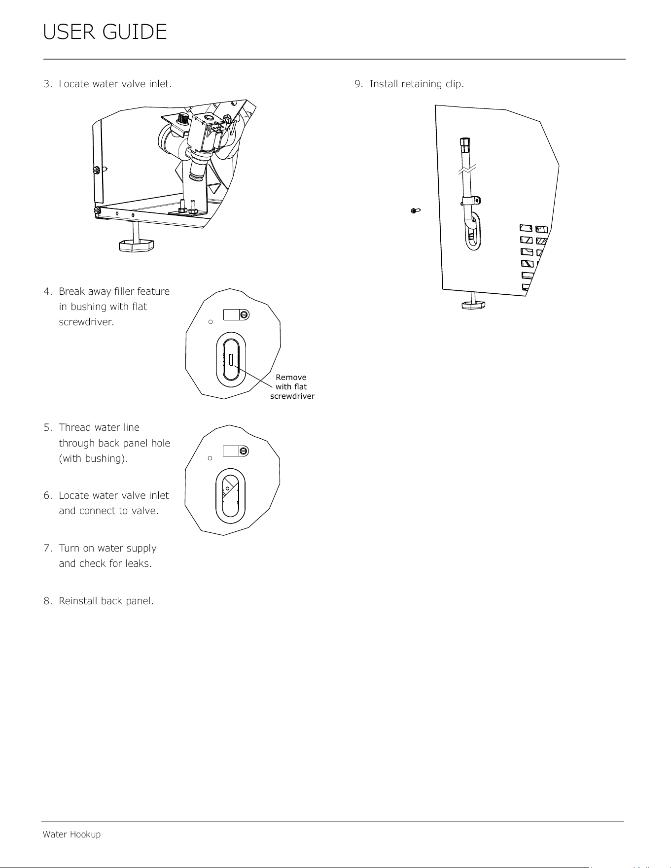
3. Locate water valve inlet.
4. Break away filler feature
in bushing with flat
screwdriver.
5. Thread water line
through back panel hole
(with bushing).
6. Locate water valve inlet
and connect to valve.
7. Turn on water supply
and check for leaks.
8. Reinstall back panel.
9. Install retaining clip.
Remove
ZLWKɠDW
screwdriver
11
USER GUIDE
Anti-Tip Bracket
Anti-Tip Bracket
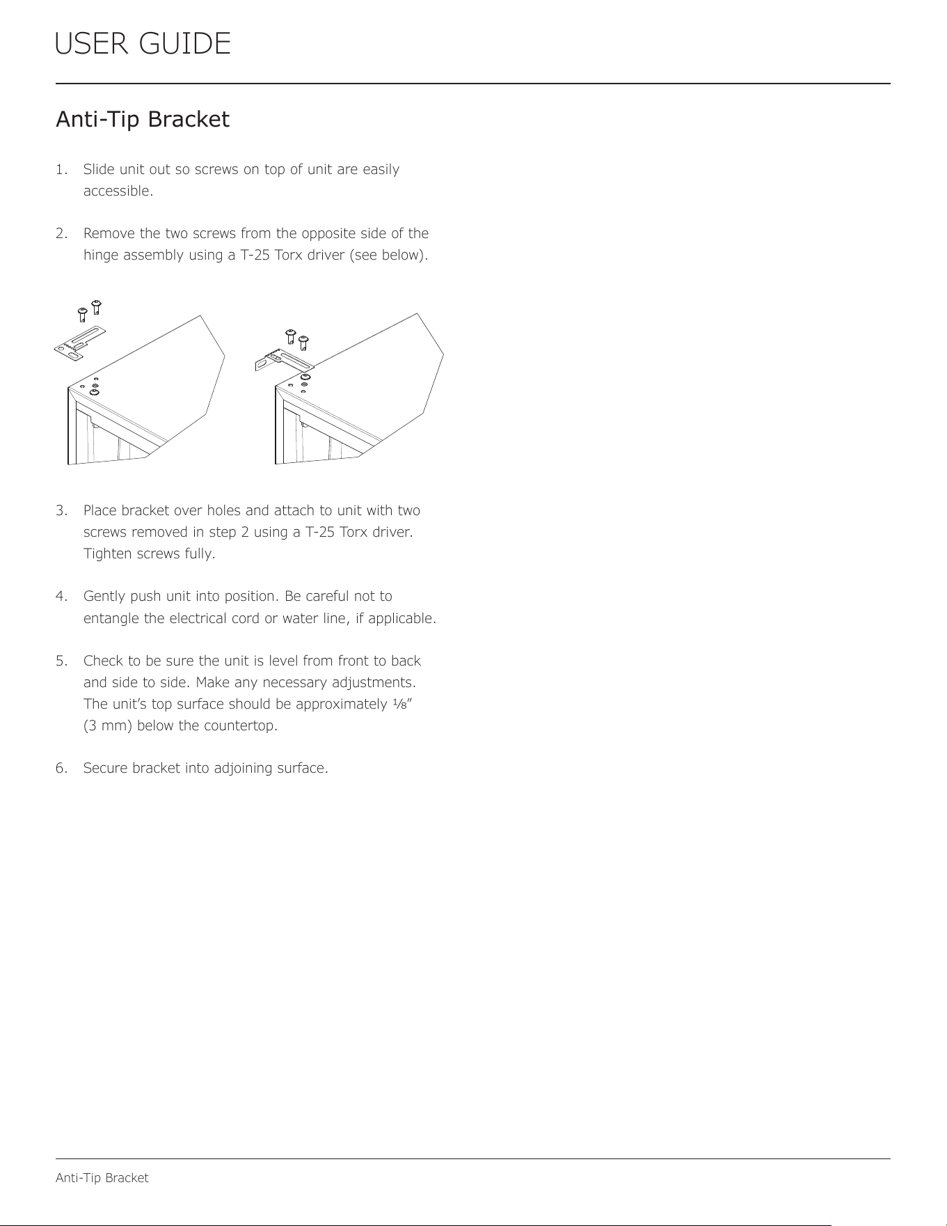
1. Slide unit out so screws on top of unit are easily
accessible.
2. Remove the two screws from the opposite side of the
hinge assembly using a T-25 Torx driver (see below).
3. Place bracket over holes and attach to unit with two
screws removed in step 2 using a T-25 Torx driver.
Tighten screws fully.
4. Gently push unit into position. Be careful not to
entangle the electrical cord or water line, if applicable.
5. Check to be sure the unit is level from front to back
and side to side. Make any necessary adjustments.
The unit’s top surface should be approximately 1⁄8”
(3 mm) below the countertop.
6. Secure bracket into adjoining surface.
12
USER GUIDE
General Installation
General Installation
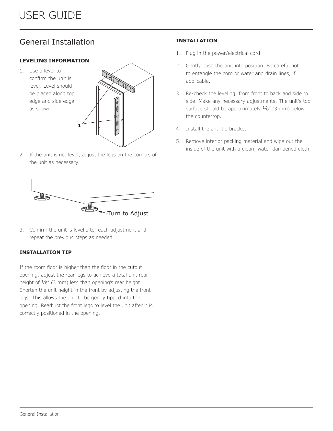
LEVELING INFORMATION
1. Use a level to
conrm the unit is
level. Level should
be placed along top
edge and side edge
as shown.
2. If the unit is not level, adjust the legs on the corners of
the unit as necessary.
3. Conrm the unit is level after each adjustment and
repeat the previous steps as needed.
INSTALLATION TIP
If the room oor is higher than the oor in the cutout
opening, adjust the rear legs to achieve a total unit rear
height of
1⁄8” (3 mm) less than opening’s rear height.
Shorten the unit height in the front by adjusting the front
legs. This allows the unit to be gently tipped into the
opening. Readjust the front legs to level the unit after it is
correctly positioned in the opening.
INSTALLATION
1. Plug in the power/electrical cord.
2. Gently push the unit into position. Be careful not
to entangle the cord or water and drain lines, if
applicable.
3. Re-check the leveling, from front to back and side to
side. Make any necessary adjustments. The unit’s top
surface should be approximately
1⁄8” (3 mm) below
the countertop.
4. Install the anti-tip bracket.
5. Remove interior packing material and wipe out the
inside of the unit with a clean, water-dampened cloth.
1
Turn to Adjust
13
USER GUIDE
Grille Installation
Grille Installation
REMOVING AND INSTALLING GRILLE
Disconnect electric power to the unit before
removing the grille.
When using the unit, the grille must be installed.
DO NOT touch the condenser ns. The condenser
ns are SHARP and can be easily damaged.
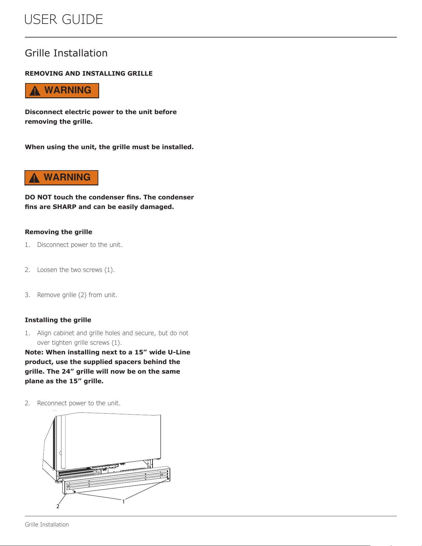
Removing the grille
1. Disconnect power to the unit.
2. Loosen the two screws (1).
3. Remove grille (2) from unit.
Installing the grille
1. Align cabinet and grille holes and secure, but do not
over tighten grille screws (1).
Note: When installing next to a 15” wide U-Line
product, use the supplied spacers behind the
grille. The 24” grille will now be on the same
plane as the 15” grille.
2. Reconnect power to the unit.
WARNING
!
WARNING
!
1
2
14
USER GUIDE
Door Swing
Door Swing
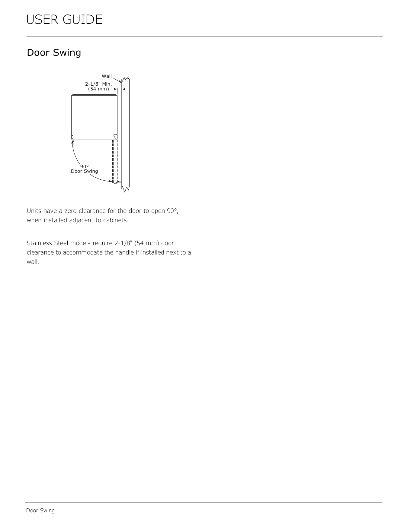
Units have a zero clearance for the door to open 90°,
when installed adjacent to cabinets.
Stainless Steel models require 2-1/8" (54 mm) door
clearance to accommodate the handle if installed next to a
wall.
Wall
90°
Door Swing
2-1/8" Min.
(54 mm)
15
USER GUIDE
Door Adjustments
Door Adjustments
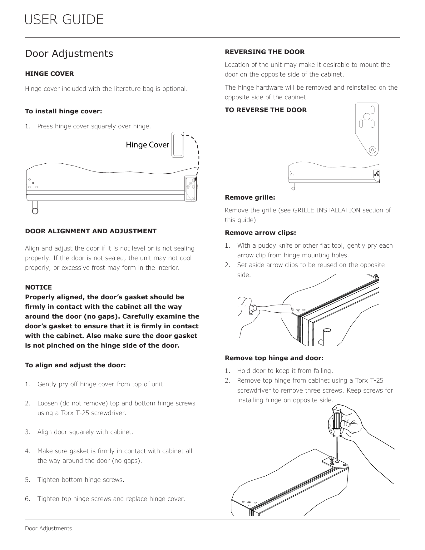
HINGE COVER
Hinge cover included with the literature bag is optional.
To install hinge cover:
1. Press hinge cover squarely over hinge.
DOOR ALIGNMENT AND ADJUSTMENT
Align and adjust the door if it is not level or is not sealing
properly. If the door is not sealed, the unit may not cool
properly, or excessive frost may form in the interior.
NOTICE
Properly aligned, the door’s gasket should be
rmly in contact with the cabinet all the way
around the door (no gaps). Carefully examine the
door’s gasket to ensure that it is rmly in contact
with the cabinet. Also make sure the door gasket
is not pinched on the hinge side of the door.
To align and adjust the door:
1. Gently pry o hinge cover from top of unit.
2. Loosen (do not remove) top and bottom hinge screws
using a Torx T-25 screwdriver.
3. Align door squarely with cabinet.
4. Make sure gasket is rmly in contact with cabinet all
the way around the door (no gaps).
5. Tighten bottom hinge screws.
6. Tighten top hinge screws and replace hinge cover.
REVERSING THE DOOR
Location of the unit may make it desirable to mount the
door on the opposite side of the cabinet.
The hinge hardware will be removed and reinstalled on the
opposite side of the cabinet.
TO REVERSE THE DOOR
Remove grille:
Remove the grille (see GRILLE INSTALLATION section of
this guide).
Remove arrow clips:
1. With a puddy knife or other at tool, gently pry each
arrow clip from hinge mounting holes.
2. Set aside arrow clips to be reused on the opposite
side.
Remove top hinge and door:
1. Hold door to keep it from falling.
2. Remove top hinge from cabinet using a Torx T-25
screwdriver to remove three screws. Keep screws for
installing hinge on opposite side.
Hinge Cover
16
USER GUIDE
Door Adjustments
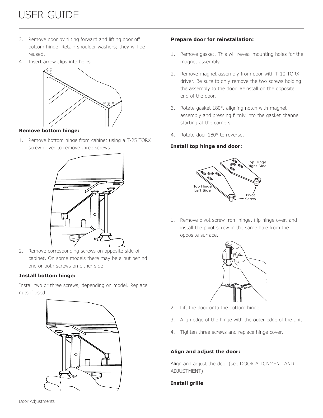
3. Remove door by tilting forward and lifting door o
bottom hinge. Retain shoulder washers; they will be
reused.
4. Insert arrow clips into holes.
Remove bottom hinge:
1. Remove bottom hinge from cabinet using a T-25 TORX
screw driver to remove three screws.
2. Remove corresponding screws on opposite side of
cabinet. On some models there may be a nut behind
one or both screws on either side.
Install bottom hinge:
Install two or three screws, depending on model. Replace
nuts if used.
Prepare door for reinstallation:
1. Remove gasket. This will reveal mounting holes for the
magnet assembly.
2. Remove magnet assembly from door with T-10 TORX
driver. Be sure to only remove the two screws holding
the assembly to the door. Reinstall on the opposite
end of the door.
3. Rotate gasket 180°, aligning notch with magnet
assembly and pressing rmly into the gasket channel
starting at the corners.
4. Rotate door 180° to reverse.
USER GUIDE
u-line.com
Door Adjustments
4. Remove door by tilting forward and lifting door o
bottom hinge. Retain shoulder washers; they will be
reused.
5. Remove three screws from hinge holes on the
opposite side. Reinstall into holes where the hinge was
removed. Take care not to scratch cabinet.
Remove bottom hinge:
1. Remove bottom hinge from cabinet using a 1/4”
socket.
2. Remove corresponding screws on opposite side of
cabinet. On some models there may be a nut behind
one or both screws on either side.
Install bottom hinge:
Install two or three screws, depending on model. Replace
nuts if used.
Prepare door for reinstallation:
1. Remove outside gasket.
2. Rotate gasket 180
º and press firmly into the gasket
channel starting at the corners.
3. Reposition inside gasket.
a.
b.
c. Using a flat tool, such as a putty knife, gently pry
off inside gasket.
d. Rotate door 180
º
and line up top edge of gasket to
marks on door and rmly press gasket into place.
(If the original adhesive no longer holds the gasket
in place, it may be necessary to apply a strip of
two-sided tape.)
Install top hinge and door:
1. Remove pivot screw from hinge, ip hinge over, and
install the pivot screw in the same hole from the
opposite surface.
2. Lift the door onto the bottom hinge.
3. Align edge of the hinge with the outer edge of the unit.
4. Tighten three screws and replace hinge cover.
Align and adjust the door:
Align and adjust the door (see DOOR ALIGNMENT AND
ADJUSTMENT)
Install grille
Before rotating door,
measure distance from
top of outside gasket to
top of inside gasket.
Measure the same
distance up from the
outside edge of the
gasket and place a light
mark on each side of
door.
Place a mark
on each side
Top of Door
a
b
Top Hinge
Right Side
Top Hinge
Left Side
Pivot
Screw
17
USER GUIDE
Free Standing Kit
Free Standing Kit
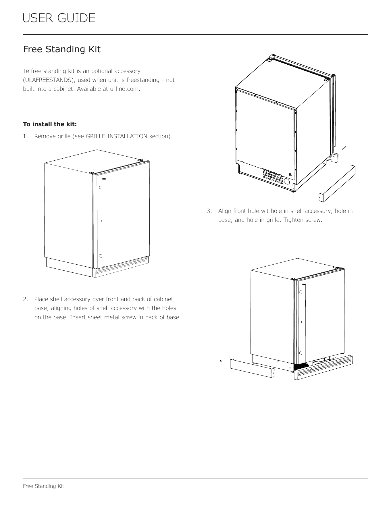
Te free standing kit is an optional accessory
(ULAFREESTANDS), used when unit is freestanding - not
built into a cabinet. Available at u-line.com.
To install the kit:
1. Remove grille (see GRILLE INSTALLATION section).
2. Place shell accessory over front and back of cabinet
base, aligning holes of shell accessory with the holes
on the base. Insert sheet metal screw in back of base.
3. Align front hole wit hole in shell accessory, hole in
base, and hole in grille. Tighten screw.
18
USER GUIDE
First Use
Temperature displayed reects actual
temperature inside unit.
Initial startup requires no adjustments. When plugged
in, the unit will begin operating under the factory default
settings. If the unit was turned o during installation,
simply press and the unit will immediately switch on. To
turn the unit o, press .
If the temperature displayed is dierent than selected, the
unit is progressing towards the selected temperature. Time
to reach set point varies based upon ambient temperature,
temperature of product loaded, door openings, etc. U-Line
recommends allowing the unit to reach set points before
loading.
NOTICE
First Use
19
USER GUIDE
Control Operation
Control Operation
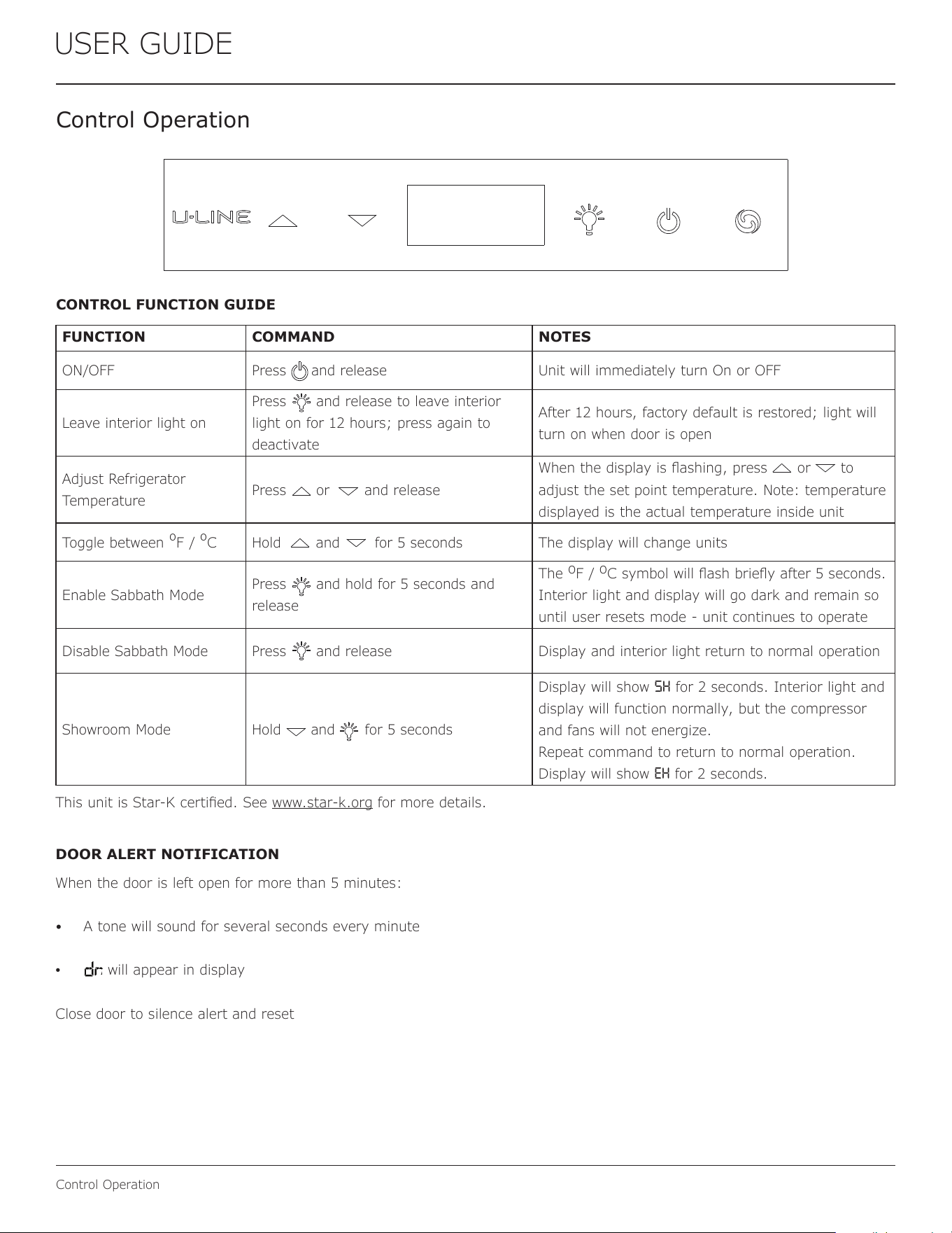
CONTROL FUNCTION GUIDE
FUNCTION COMMAND NOTES
ON/OFF Press and release Unit will immediately turn On or OFF
Leave interior light on
Press and release to leave interior
light on for 12 hours; press again to
deactivate
After 12 hours, factory default is restored; light will
turn on when door is open
Adjust Refrigerator
Temperature
Press or and release
When the display is ashing, press or to
adjust the set point temperature. Note: temperature
displayed is the actual temperature inside unit
Toggle between
º
F /
º
C Hold and for 5 seconds The display will change units
Enable Sabbath Mode
Press and hold for 5 seconds and
release
The
o
F /
o
C symbol will ash briey after 5 seconds.
Interior light and display will go dark and remain so
until user resets mode - unit continues to operate
Disable Sabbath Mode Press and release Display and interior light return to normal operation
Showroom Mode Hold and for 5 seconds
Display will show
SH for 2 seconds. Interior light and
display will function normally, but the compressor
and fans will not energize.
Repeat command to return to normal operation.
Display will show
EH for 2 seconds.
This unit is Star-K certied. See www.star-k.org for more details.
DOOR ALERT NOTIFICATION
When the door is left open for more than 5 minutes:
• A tone will sound for several seconds every minute
• will appear in display
Close door to silence alert and reset
20
USER GUIDE
Ice
Ice
ICE MAKER OPERATION
When the ice bucket is full, the ice making mechanism will
shut off. However, the refrigeration system will continue
to cool and maintain the ice supply.
NOTICE
Do not place cans or bottles in the ice
compartment because they will freeze.
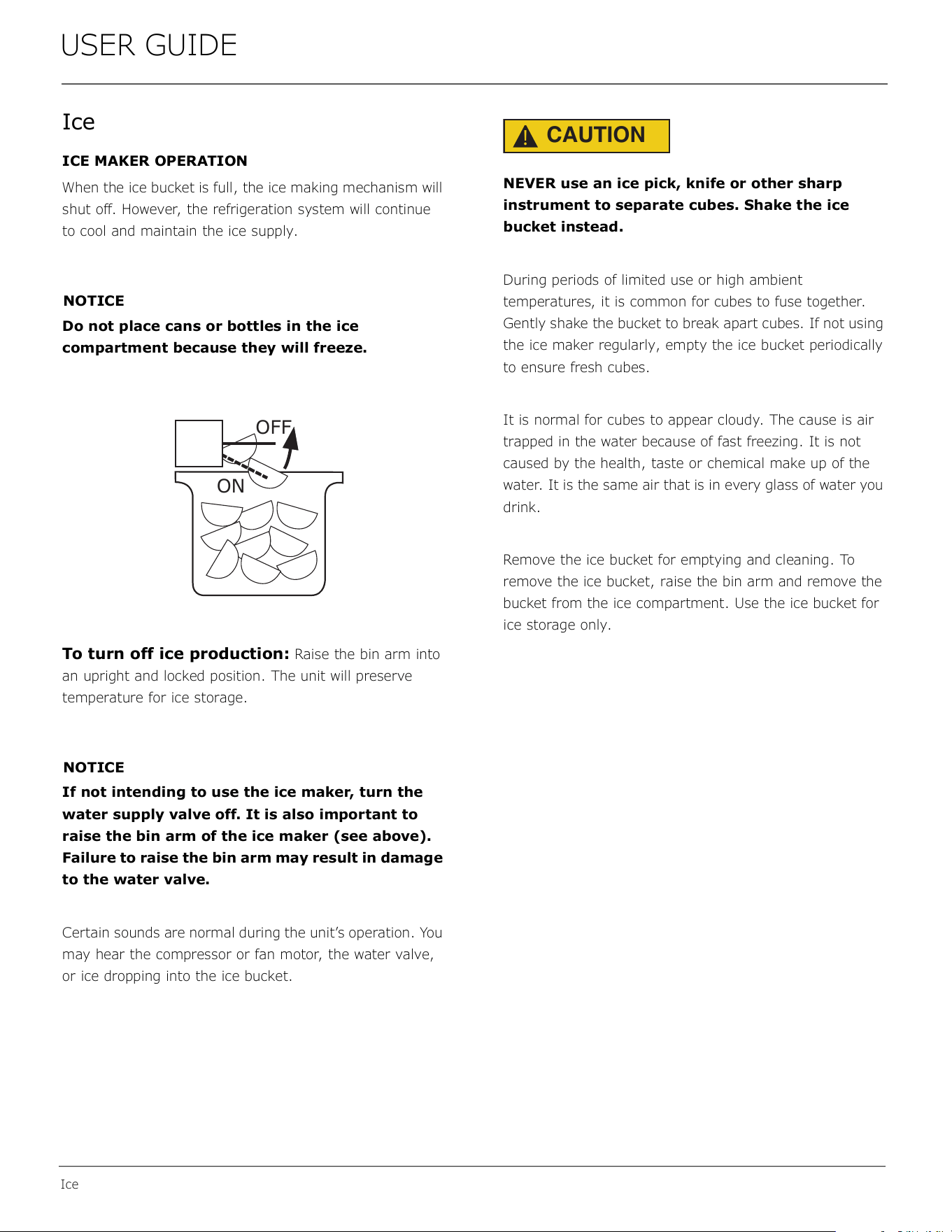
To turn off ice production: Raise the bin arm into
an upright and locked position. The unit will preserve
temperature for ice storage.
NOTICE
If not intending to use the ice maker, turn the
water supply valve off. It is also important to
raise the bin arm of the ice maker (see above).
Failure to raise the bin arm may result in damage
to the water valve.
Certain sounds are normal during the unit’s operation. You
may hear the compressor or fan motor, the water valve,
or ice dropping into the ice bucket.
CAUTION
!
NEVER use an ice pick, knife or other sharp
instrument to separate cubes. Shake the ice
bucket instead.
During periods of limited use or high ambient
temperatures, it is common for cubes to fuse together.
Gently shake the bucket to break apart cubes. If not using
the ice maker regularly, empty the ice bucket periodically
to ensure fresh cubes.
It is normal for cubes to appear cloudy. The cause is air
trapped in the water because of fast freezing. It is not
caused by the health, taste or chemical make up of the
water. It is the same air that is in every glass of water you
drink.
Remove the ice bucket for emptying and cleaning. To
remove the ice bucket, raise the bin arm and remove the
bucket from the ice compartment. Use the ice bucket for
ice storage only.
OFF
ON
21
USER GUIDE
Ice
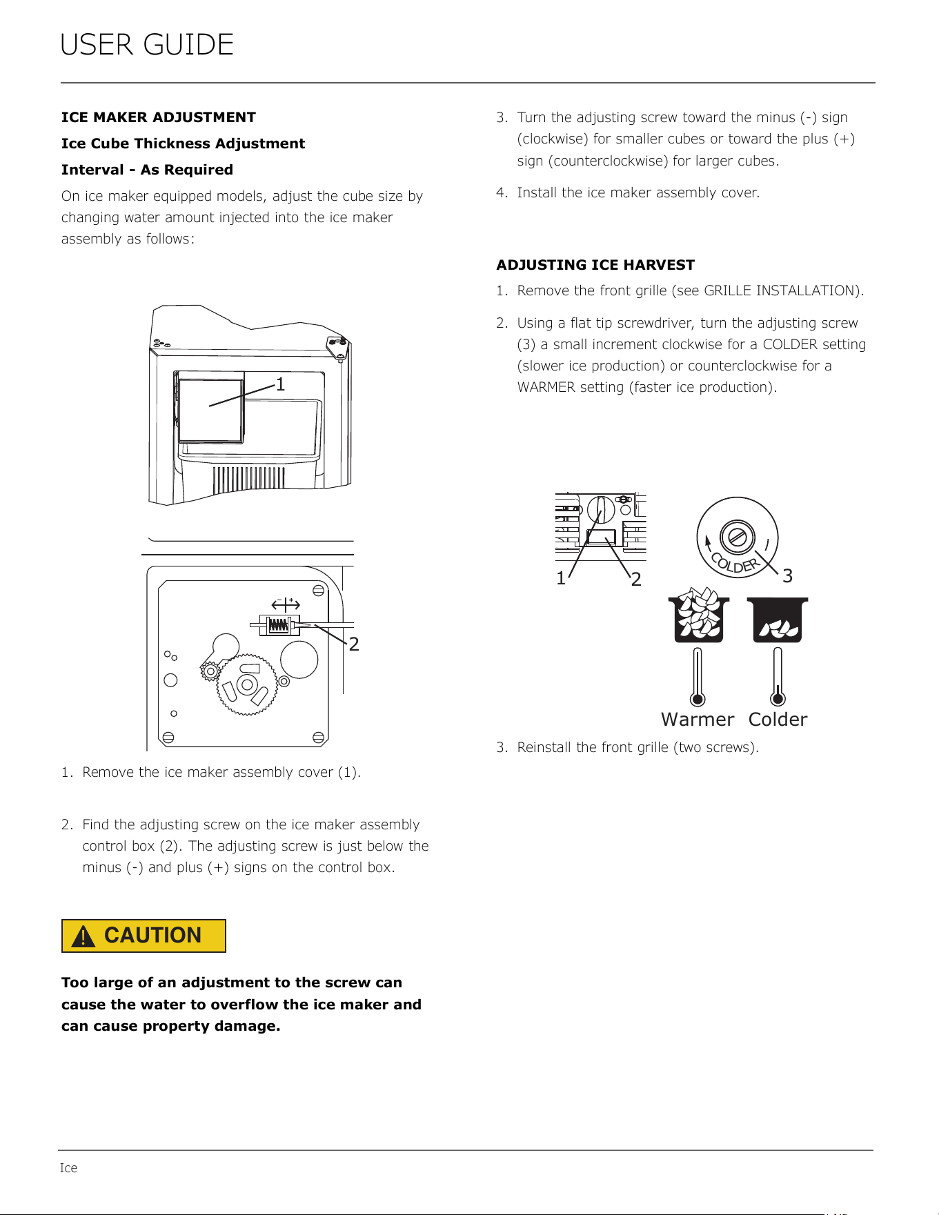
ICE MAKER ADJUSTMENT
Ice Cube Thickness Adjustment
Interval - As Required
On ice maker equipped models, adjust the cube size by
changing water amount injected into the ice maker
assembly as follows:
1. Remove the ice maker assembly cover (1).
2. Find the adjusting screw on the ice maker assembly
control box (2). The adjusting screw is just below the
minus (-) and plus (+) signs on the control box.
CAUTION
!
Too large of an adjustment to the screw can
cause the water to overflow the ice maker and
can cause property damage.
3. Turn the adjusting screw toward the minus (-) sign
(clockwise) for smaller cubes or toward the plus (+)
sign (counterclockwise) for larger cubes.
4. Install the ice maker assembly cover.
ADJUSTING ICE HARVEST
1. Remove the front grille (see GRILLE INSTALLATION).
2. Using a flat tip screwdriver, turn the adjusting screw
(3) a small increment clockwise for a COLDER setting
(slower ice production) or counterclockwise for a
WARMER setting (faster ice production).
3. Reinstall the front grille (two screws).
1
2
C
O
L
D
E
R
Warmer Colder
3
1
2
22
USER GUIDE
Airow & Product Loading
Restricting airow may result in poor product
performance, product failure, and uneven internal
temperatures and may freeze contents.
• Do not block the front grille - no additional clearance
around sides, top or rear of unit is needed for ventilation
• Do not install behind a closed door
• When loading, leave space between internal fans, vents,
and side walls to allow air to circulate freely
NOTICE
AIRFLOW
External
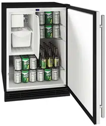
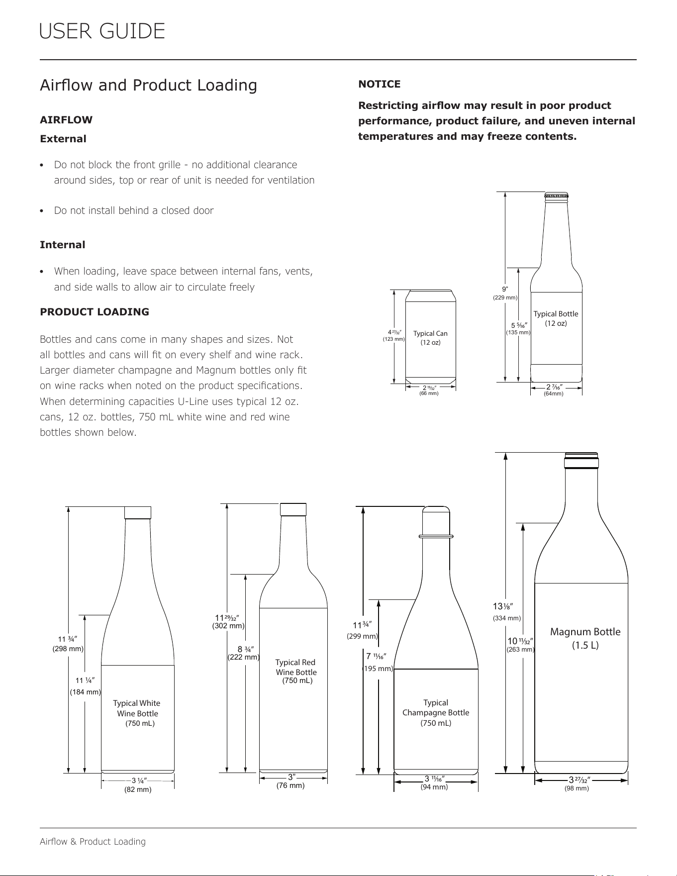
PRODUCT LOADING
Bottles and cans come in many shapes and sizes. Not
all bottles and cans will t on every shelf and wine rack.
Larger diameter champagne and Magnum bottles only t
on wine racks when noted on the product specications.
When determining capacities U-Line uses typical 12 oz.
cans, 12 oz. bottles, 750 mL white wine and red wine
bottles shown below.
Airow and Product Loading
Typical Can
(12 oz)
4
(123 mm)
(66 mm)
2
27⁄32”
19⁄32”
Typical Bottle
(12 oz)
9”
5
2
7⁄16”
5⁄16”
(135 mm)
(64mm)
(229 mm)
Typical White
Wine Bottle
11
(298 mm)
(750 mL)
3
¾”
(184 mm)
(82 mm)
11
¼”
¼”
Typical Red
Wine Bottle
11
(302 mm)
8
3”
29⁄32”
¾”
(222 mm)
(750 mL)
(76 mm)
Typical
Champagne Bottle
(750 mL)
3 11⁄16”
7
¾”
11⁄16”
(299 mm)
(94 mm)
(195 mm)
11
Magnum Bottle
(1.5 L)
13
10
3
1⁄8”
(334 mm)
11⁄32”
(263 mm)
27⁄32”
(98 mm)
Internal
23
USER GUIDE
Interior Adjustments
Interior Adjustments
INTERIOR SHELVES
Removing and Installing Interior Shelves
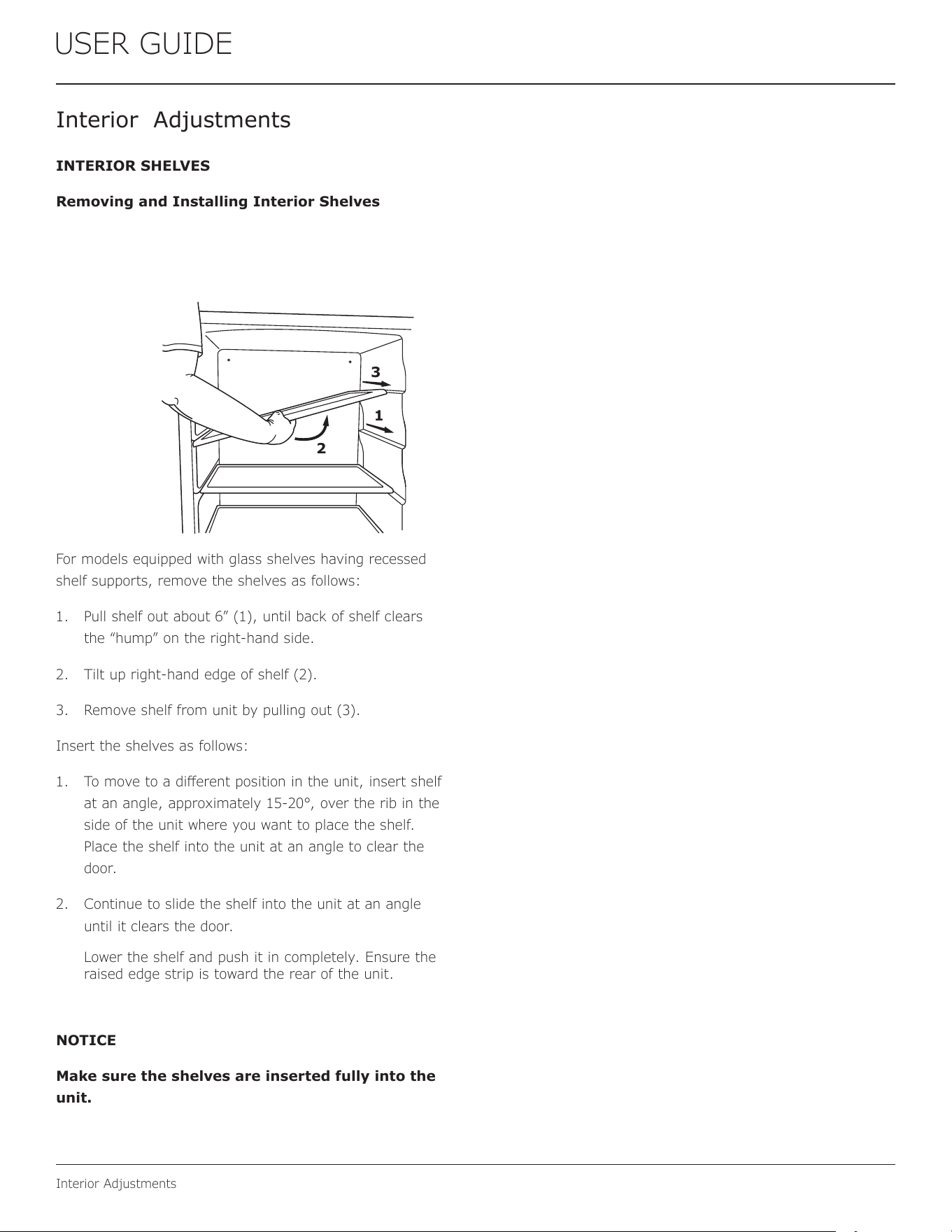
For models equipped with glass shelves having recessed
shelf supports, remove the shelves as follows:
1. Pull shelf out about 6” (1), until back of shelf clears
the “hump” on the right-hand side.
2. Tilt up right-hand edge of shelf (2).
3. Remove shelf from unit by pulling out (3).
Insert the shelves as follows:
1. To move to a dierent position in the unit, insert shelf
at an angle, approximately 15-20°, over the rib in the
side of the unit where you want to place the shelf.
Place the shelf into the unit at an angle to clear the
door.
2. Continue to slide the shelf into the unit at an angle
until it clears the door.
Lower the shelf and push it in completely. Ensure the
raised edge strip is toward the rear of the unit.
NOTICE
Make sure the shelves are inserted fully into the
unit.
2
3
1
24
USER GUIDE
Cleaning
Cleaning
Stainless Models
Stainless door panels and handles can discolor when
exposed to chlorine gas, pool chemicals, saltwater or
cleaners with bleach.
Keep your stainless unit looking new by cleaning with a
good quality all-in-one stainless steel cleaner and polish
monthly. For best results use Claire
®
Stainless Steel
Polish and Cleaner. Comparable products are acceptable.
Frequent cleaning will remove surface contamination that
could lead to rust. Some installations may require cleaning
weekly.
Do not clean with steel wool pads.
Do not use stainless steel cleaners or polishes on
any glass surfaces.
Clean any glass surfaces with a non-chlorine glass
cleaner.
Do not use cleaners not specifically intended for
stainless steel on stainless steel surfaces (this
includes glass, tile and counter cleaners).
If any surface discoloring or rusting appears, clean it
quickly with Bon-Ami
®
or Barkeepers Friend Cleanser
®
and a nonabrasive cloth. Always clean with the grain.
Always finish with Claire
®
Stainless Steel Polish and
Cleaner or comparable product to prevent further
problems.
Using abrasive pads such as Scotchbrite™ will
cause the graining in the stainless steel to
become blurred.
Rust not cleaned up promptly can penetrate the
surface of the stainless steel and complete
removal of the rust may not be possible.
Integrated Models
To clean integrated panels, use household cleaner per the
cabinet manufacturer’s recommendation.
INTERIOR CLEANING
Disconnect power to the unit.
Clean the interior and all removed components using a
mild nonabrasive detergent and warm water solution
applied with a soft sponge or non-abrasive cloth.
Rinse the interior using a soft sponge and clean water.
Do not use any solvent-based or abrasive
cleaners. These types of cleaners may transfer taste to
the interior products and damage or discolor the lining.
DEFROSTING
Under normal conditions this unit does not require manual
defrosting. Minor frost on the rear wall or visible through
the evaporator plate vents is normal and will melt during
each off cycle.
If there is excessive build-up of 1/4" (6 mm) or more,
manually defrost the unit.
Ensure the door is closing and sealing properly.
High ambient temperature and excessive humidity can
also produce frost.
CAUTION
!
DO NOT use an ice pick or other sharp
instrument to help speed up defrosting. These
instruments can puncture the inner lining or
damage the cooling unit. DO NOT use any type of
heater to defrost. Using a heater to speed up
defrosting can cause personal injury and
damage to the inner lining.
25
USER GUIDE
Cleaning
NOTICE
The drain pan was not designed to capture the
water created when manually defrosting. To
prevent water from overflowing the drain pan
and possibly damaging water sensitive flooring,
the unit must be removed from cabinetry.
To defrost:
1. Disconnect power to the unit.
2. Remove all products from the interior.
3. Prop the door in an open position (2 in. [50 mm]
minimum).
4. Allow the frost to melt naturally.
5. After the frost melts completely clean the interior and
all removed components. (See INTERIOR CLEANING).
6. When the interior is dry, reconnect power and turn unit
on.
26
USER GUIDE
Cleaning Condenser
USER GUIDE
Cleaning Condenser 1
u-line.com
SAFETY • INSTALLATION & INTEGRATION • OPERATING INSTRUCTIONS • MAINTENANCE • SERVICE
Cleaning Condenser
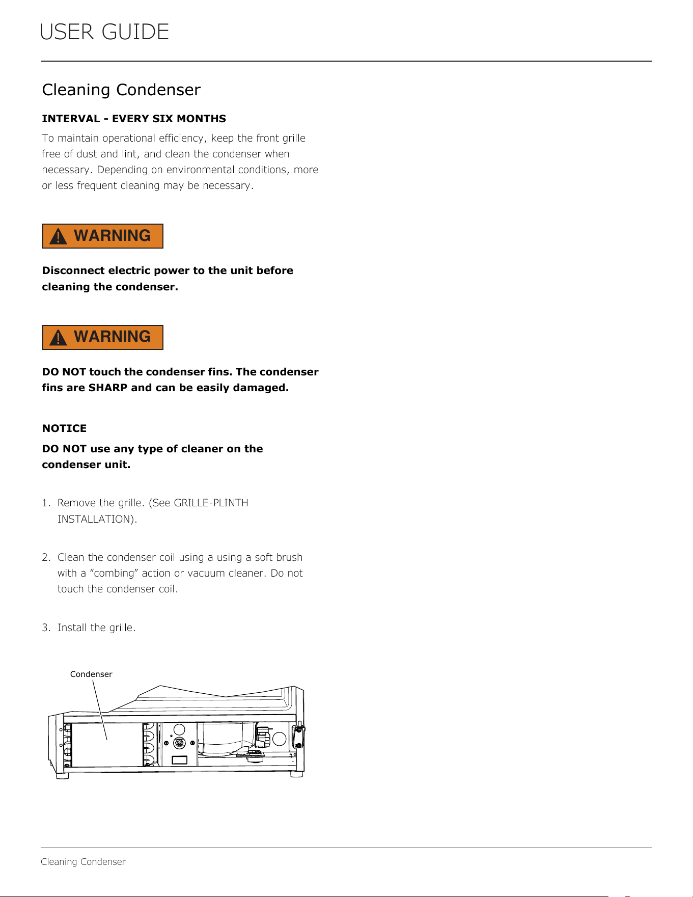
INTERVAL - EVERY SIX MONTHS
To maintain operational efficiency, keep the front grille
free of dust and lint, and clean the condenser when
necessary. Depending on environmental conditions, more
or less frequent cleaning may be necessary.
WARNING
!
Disconnect electric power to the unit before
cleaning the condenser.
WARNING
!
DO NOT touch the condenser fins. The condenser
fins are SHARP and can be easily damaged.
NOTICE
DO NOT use any type of cleaner on the
condenser unit.
1. Remove the grille. (See GRILLE-PLINTH
INSTALLATION).
2. Clean the condenser coil using a using a soft brush
with a “combing” action or vacuum cleaner. Do not
touch the condenser coil.
3. Install the grille.
Condenser
27
USER GUIDE
Extended Non-Use
Extended Non-Use
VACATION/HOLIDAY, PROLONGED SHUTDOWN
The following steps are recommended for periods of
extended non-use:
1. Remove all consumable content from the unit.
2. Disconnect the power cord from its outlet/socket
and leave it disconnected until the unit is returned to
service.
3. If any ice is visible inside the unit, allow ice to thaw
naturally.
4. Clean and dry the interior of the unit. Ensure all water
has been removed from the unit.
5. Clean the system. (See CLEANING)
6. The door must remain open to prevent formation of
mold and mildew. Open door a minimum of 2” (50
mm) to provide the necessary ventilation.
WINTERIZATION
If the unit will be exposed to temperatures of 40
o
F (5
o
C) or
less, the steps above must be followed.
For questions regarding winterization, please call
U-Line at 414.354.0300.
CAUTION
!
Damage caused by freezing temperatures is not
covered by the warranty.
28
USER GUIDE
Troubleshooting
If you think your U-Line product is malfunctioning, read
the CONTROL OPERATION section to clearly understand
the function of the control.
If the problem persists, read the NORMAL OPERATING
SOUNDS and TROUBLESHOOTING GUIDE sections below
to help you quickly identify common problems and
possible causes and remedies. Most often, this will resolve
the problem without the need to call for service.
If your product needs service, please go to
www.U-Line.com and navigate to the Find a Servicer page
to locate a U-Line Authorized servicer. If your product is in
warranty please make sure to register it at
www.U-Line.com/u-lineregistration. If you have any
issues following this process you can contact the U-Line
Corporation by phone at +1.414.354.0300
If you call, you will need your product Model and Serial
Numbers. This information appears on the Model and Serial
number plate located on the interior of your product, most
often placed on the ceiling.
All models incorporate rigid foam insulated cabinets to
provide high thermal eciency and maximum sound
reduction for its internal working components. Despite this
technology, your model may make sounds that are
unfamiliar.
Normal operating sounds may be more noticeable because
of the unit’s environment. Hard surfaces such as cabinets,
wood, vinyl or tiled oors and paneled walls have a
tendency to reect normal appliance operating noises.
Listed below are common refrigeration components with a
brief description of the normal operating sounds they
make. NOTE: Your product may not contain all the
components listed.
• Compressor: The compressor makes a hum or pulsing
sound that may be heard when it operates.
BEFORE CALLING FOR SERVICE
TROUBLESHOOTING GUIDE
ELECTROCUTION HAZARD. Never attempt to
repair or perform maintenance on the unit
before disconnecting the main electrical power.
Troubleshooting - What to check when problems occur:
NORMAL OPERATING SOUNDS
Troubleshooting
• Evaporator: Refrigerant owing through an evaporator
may sound like boiling liquid.
• Condenser Fan: Air moving through a condenser may
be heard.
• Running Water: As your unit continues to produce
ice you will hear water owing into the collection
chambers and running through the evaporator.
DANGER
!
Problem Possible Cause and Remedy
Unit Does Not
Operate.
Electronic
Display Blank.
No electrical supply. Plug unit in or
check
circuit breaker.
Display
Showing Error
Code.
If display shows error “dr”, check to
make sure door is sealing correctly.
Make sure to close door completely. If
sealing the door
does not clear the error, contact U-Line
service for more information.
Unit Develops
Condensation
on External
Surfaces.
The unit is exposed to excessive
humidity.
Moisture will dissipate as humidity
levels decrease.
Poor Ice
Quality.
Unit may not be level. Check if unit is
level.
Ice maker system may be dirty. Clean
the ice maker.
No Ice
Production.
Ensure water is being supplied to the
unit.
Verify the ice making unit is turned on.
Not Enough
Ice.
Ensure the condenser coil is clean and
free of any dirt or lint build-up.
Water in Ice
Bin.
Drain may be restricted, ensure drain
is free of foreign debris.
29
USER GUIDE
Wire Diagram
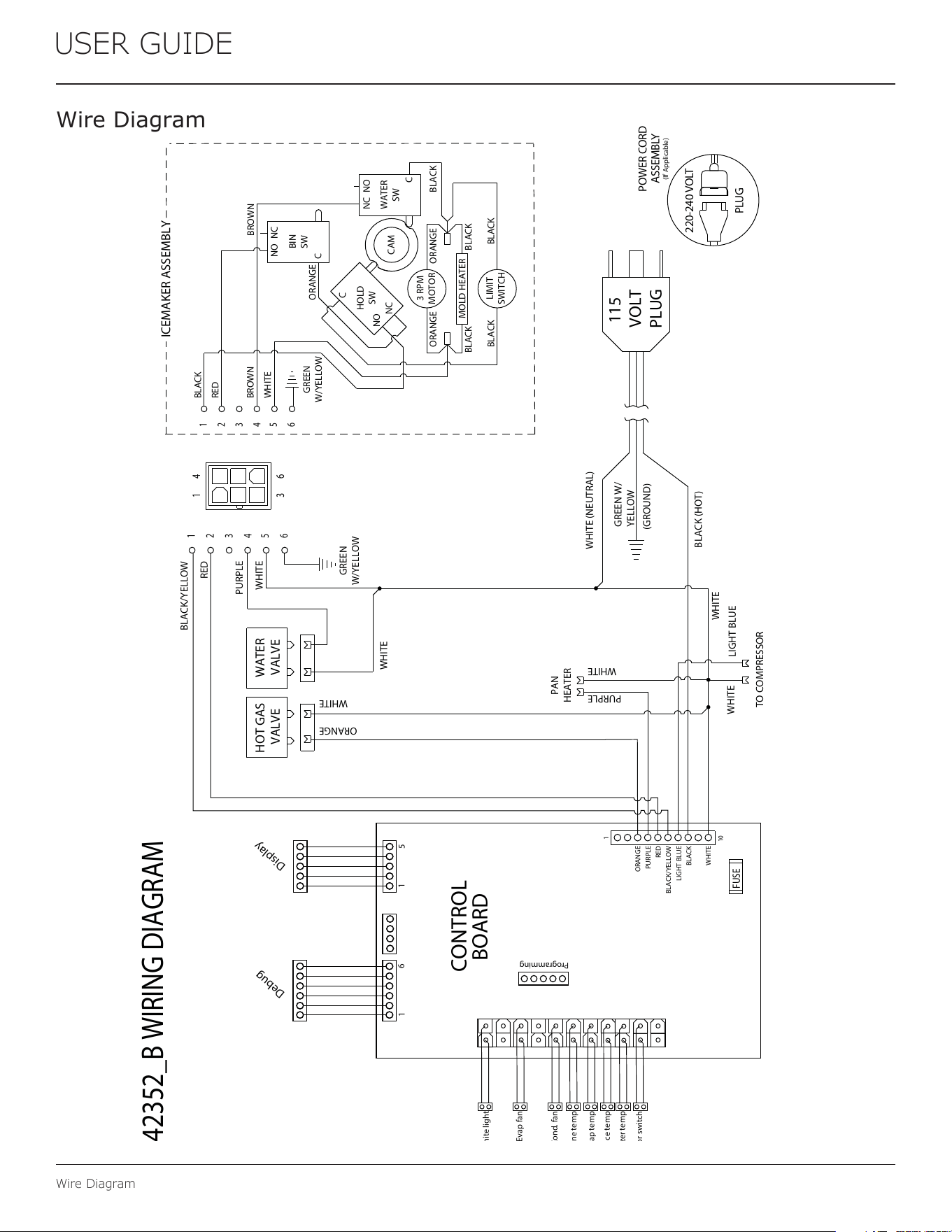
Wire Diagram
White light
Evap fan
Door switch
Cond. fan
Zone temp
Evap temp
Ice temp
Freezer temp
Programming
Debug
Display
POWER CORD
ASSEMBLY
220-240 VOLT
PLUG
1
1
1
6
5
10
GREEN W/
YELLOW
BLACK (HOT)
WHITE (NEUTRAL)
(GROUND)
WHITE
WHITE
LIGHT BLUE
TO COMPRESSOR
PURPLE
WHITE
PAN
HEATER
115
VOLT
PLUG
ORANGE
RED
PURPLE
BLACK/YELLOW
LIGHT BLUE
BLACK
WHITE
(If Applicable)
CONTROL
BOARD
FUSE
WATER
VALVE
HOT GAS
VALVE
ICEMAKER ASSEMBLY
SW
C
GREEN
W/YELLOW
BLACK
RED
BROWN
WHITE
ORANGE
GREEN
W/YELLOW
BLACK/YELLOW
RED
PURPLE
WHITE
WHITE
WHITE
ORANGE
1
2
3
4
5
6
1
2
3
4
5
6
1 4
3 6
3 RPM
MOTOR
MOLD HEATER
HOLD
SW
NO
NC
C
BIN
NO NC
NONC
WATER
SW
C
BROWN
ORANGE ORANGE
BLACK BLACK
BLACK BLACK
BLACK
LIMIT
SWITCH
CAM
42352_B WIRING DIAGRAM
30
USER GUIDE
Product Liability
Product Liability
Field service technicians are authorized to make an initial
assessment in the event of reported damages. If there are
any questions about the process involved, the technician
should call U-Line for further explanation.
While inspecting for defects or installation issues, photos
should be taken to document any damages or issues found.
During the assessment, if the service technician is able to
nd the source of the damage and it can be resolved by
replacement of a part, the servicer is authorized to replace
the part in question. The part that caused the damage
must be returned to U-Line in its entirety. The part must
be clearly labeled with the serial number of the unit it was
removed from, the date, and the servicer who removed the
part.
If the service technician determines the damage is the
result of installation issues (water connection/drain, etc.),
the consumer would be notied and the issues shall be
resolved at the direction of the consumer.
If damage is evident and the service technician is
unable to nd the source, U-Line must be contacted at
+1.414.354.0300 for further direction.
8900 N. 55th Street • Milwaukee, WI 53223
T: +1.414.354.0300 • F: +1.414.354.5696
Website: www.u-line.com
Right product. Right place.
Right temperature Since 1962.
31
USER GUIDE
Parts
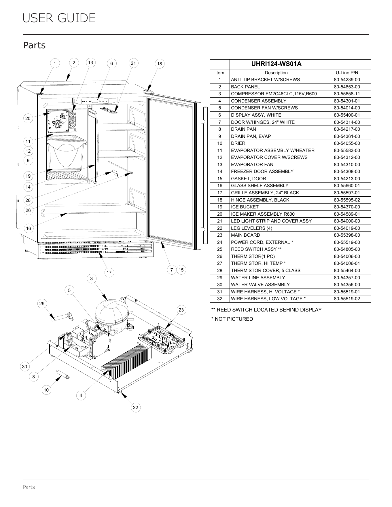
Pa rts
UHRI124-WS01A
Item Description U-Line P/N
1 ANTI TIP BRACKET W/SCREWS 80-54239-00
2 BACK PANEL 80-54853-00
3 COMPRESSOR EM2C46CLC,115V,R600 80-55658-11
4 CONDENSER ASSEMBLY 80-54301-01
5 CONDENSER FAN W/SCREWS 80-54014-00
6 DISPLAY ASSY, WHITE 80-55400-01
7 DOOR W/HINGES, 24" WHITE 80-54314-00
8 DRAIN PAN 80-54217-00
9 DRAIN PAN, EVAP 80-54361-00
10 DRIER 80-54055-00
11 EVAPORATOR ASSEMBLY W/HEATER 80-55583-00
12 EVAPORATOR COVER W/SCREWS 80-54312-00
13 EVAPORATOR FAN 80-54310-00
14 FREEZER DOOR ASSEMBLY 80-54308-00
15 GASKET, DOOR 80-54213-00
16 GLASS SHELF ASSEMBLY 80-55660-01
17 GRILLE ASSEMBLY, 24" BLACK 80-55597-01
18 HINGE ASSEMBLY, BLACK 80-55595-02
19 ICE BUCKET 80-54370-00
20 ICE MAKER ASSEMBLY R600 80-54589-01
21 LED LIGHT STRIP AND COVER ASSY 80-54000-00
22 LEG LEVELERS (4) 80-54019-00
23 MAIN BOARD 80-55398-00
24 POWER CORD, EXTERNAL * 80-55519-00
25 REED SWITCH ASSY ** 80-54805-00
26 THERMISTOR(1 PC) 80-54006-00
27 THERMISTOR, HI TEMP * 80-54006-01
28 THERMISTOR COVER, 5 CLASS 80-55464-00
29 WATER LINE ASSEMBLY 80-54357-00
30 WATER VALVE ASSEMBLY 80-54356-00
31 WIRE HARNESS, HI VOLTAGE * 80-55519-01
32 WIRE HARNESS, LOW VOLTAGE * 80-55519-02
* NOT PICTURED
** REED SWITCH LOCATED BEHIND DISPLAY
12
9
1
2
6
7 15
11
13
14
16
17
18
19
20
21
26
28
3
4
5
8
10
22
30
29
23
32
USER GUIDE
R-600A Specications
USER GUIDE
R-600A Specifications 1
u-line.com
SAFETY • INSTALLATION & INTEGRATION • OPERATING INSTRUCTIONS • MAINTENANCE • SERVICE
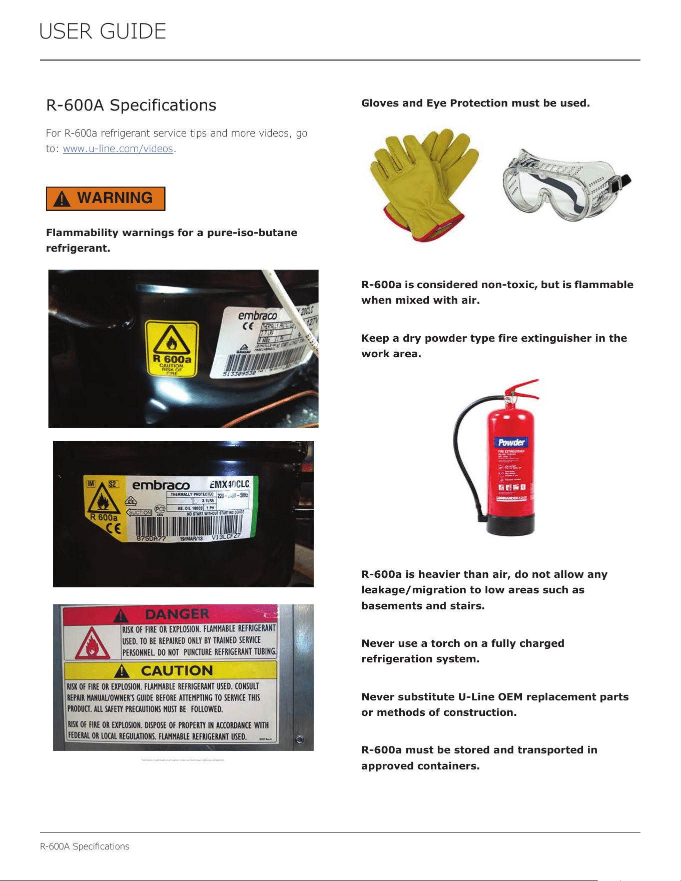
R-600A Specifications
For R-600a refrigerant service tips and more videos, go
to: www.u-line.com/videos
.
WARNING
!
Flammability warnings for a pure-iso-butane
refrigerant.
Technician m ust observe all fe deral, state an d local laws regard ing refrigerant s.
Gloves and Eye Protection must be used.
R-600a is considered non-toxic, but is flammable
when mixed with air.
Keep a dry powder type fire extinguisher in the
work area.
R-600a is heavier than air, do not allow any
leakage/migration to low areas such as
basements and stairs.
Never use a torch on a fully charged
refrigeration system.
Never substitute U-Line OEM replacement parts
or methods of construction.
R-600a must be stored and transported in
approved containers.
33
R-600A Specications
USER GUIDE
USER GUIDE
R-600A Specifications 2
u-line.com
SAFETY • INSTALLATION & INTEGRATION • OPERATING INSTRUCTIONS • MAINTENANCE • SERVICE
WARNING
!
Only skilled and well trained service technicians
permitted to service R-600a equipped products.
All tools and equipment must be approved for
use with R-600a refrigerant.
Local, state and federal laws, standards must be
observed along with proper certification and
licensing.
Ventilation is required during servicing.
No conversions to R-600a from any other
refrigerants. OEM R-600a equipped unit only.
Service area must be free of ignition sources.
No smoking is allowed in the service area.
All replacement electrical components must be
OEM and installed properly (sealed and
covered).
If the evaporator is cold prior to service, it must
be thawed prior to service.
When using a vacuum pump, start pump before
opening refrigeration system.
Vacuum pump and recovery equipment should
be at least 10 feet from the work area.
It is recommended that a simple LPG gas
detector is on site during service.
Ensure that all R-600a is removed from the
system prior to brazing any part of the sealed
system.
Only a clean, dry leak free system should be
charged with R-600a.
R-600A SPECIFICATIONS/LABELING
R-600a equipped products are labeled (both the unit and
the compressor).
R-600a is colorless and odorless.
R-600a is considered non-toxic, but is flammable when
mixed with air.
Do not remove or alter any R-600a labeling on the
product.
Use only a refrigerant grade R-600a from a properly
labeled container.
RECOVERING/RECLAIMING R-600A
(R-600a has been exempted from recovery/reclaiming
requirements by the US EPA)
Recovery/Reclaiming equipment must be approved for use
with R-600a.
Ensure the evaporator is at room temperature prior to
recovery/reclaiming R-600a.
Use a common piercing pliers or piercing valve to remove
R-600a from the compressor process tube. (Note: Piercing
devices must not be left on the system and must be
replaced with a Schrader type valve.)
34
USER GUIDE
R-600A Specications
USER GUIDE
R-600A Specifications 3
u-line.com
SAFETY • INSTALLATION & INTEGRATION • OPERATING INSTRUCTIONS • MAINTENANCE • SERVICE
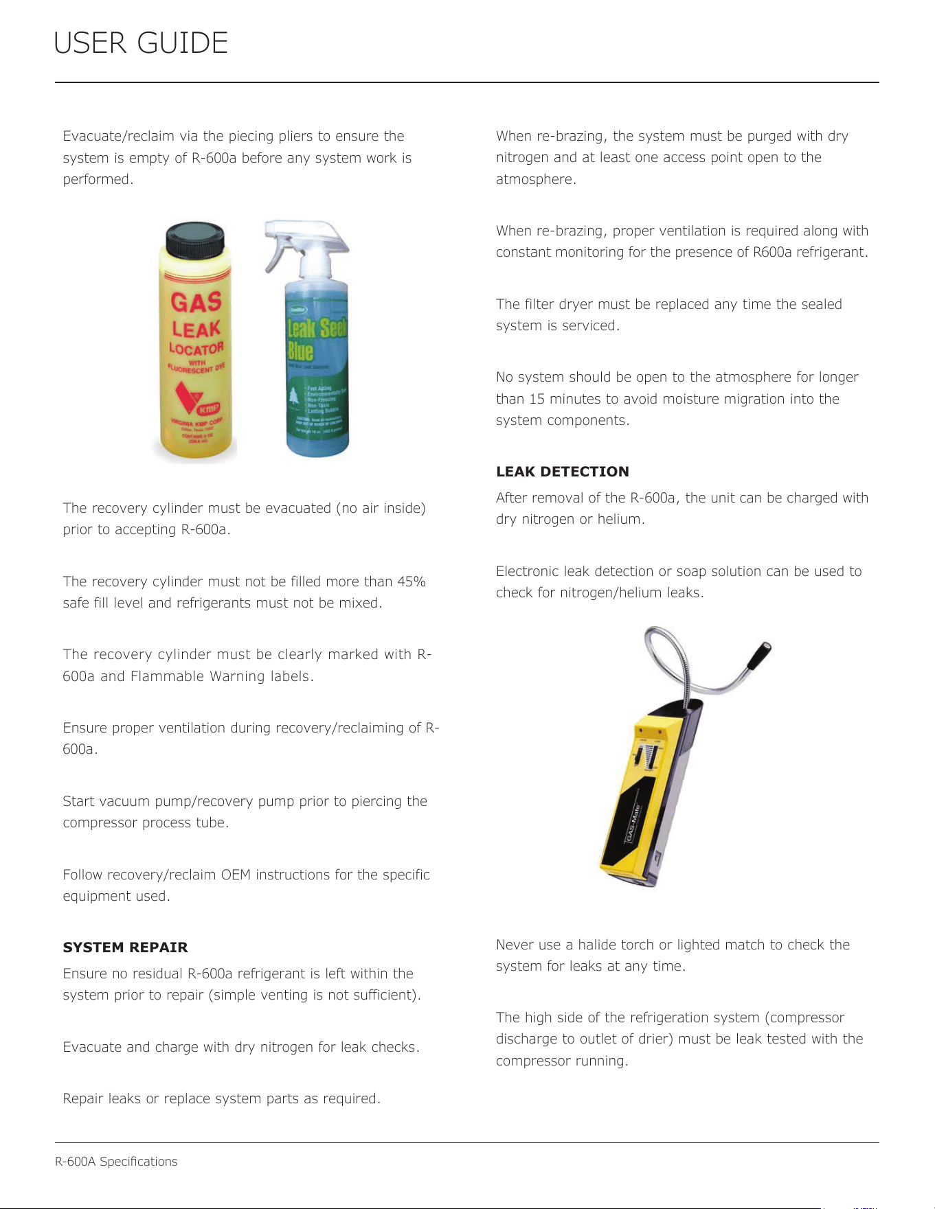
Evacuate/reclaim via the piecing pliers to ensure the
system is empty of R-600a before any system work is
performed.
The recovery cylinder must be evacuated (no air inside)
prior to accepting R-600a.
The recovery cylinder must not be filled more than 45%
safe fill level and refrigerants must not be mixed.
The recovery cylinder must be clearly marked with R-
600a and Flammable Warning labels.
Ensure proper ventilation during recovery/reclaiming of R-
600a.
Start vacuum pump/recovery pump prior to piercing the
compressor process tube.
Follow recovery/reclaim OEM instructions for the specific
equipment used.
SYSTEM REPAIR
Ensure no residual R-600a refrigerant is left within the
system prior to repair (simple venting is not sufficient).
Evacuate and charge with dry nitrogen for leak checks.
Repair leaks or replace system parts as required.
When re-brazing, the system must be purged with dry
nitrogen and at least one access point open to the
atmosphere.
When re-brazing, proper ventilation is required along with
constant monitoring for the presence of R600a refrigerant.
The filter dryer must be replaced any time the sealed
system is serviced.
No system should be open to the atmosphere for longer
than 15 minutes to avoid moisture migration into the
system components.
LEAK DETECTION
After removal of the R-600a, the unit can be charged with
dry nitrogen or helium.
Electronic leak detection or soap solution can be used to
check for nitrogen/helium leaks.
Never use a halide torch or lighted match to check the
system for leaks at any time.
The high side of the refrigeration system (compressor
discharge to outlet of drier) must be leak tested with the
compressor running.
35
R-600A Specications
USER GUIDE
USER GUIDE
R-600A Specifications 4
u-line.com
SAFETY • INSTALLATION & INTEGRATION • OPERATING INSTRUCTIONS • MAINTENANCE • SERVICE
The low side of the refrigeration system (evaporator,
compressor and suction line) must be leak tested with the
compressor off (equalized pressure).
RECHARGING
No air is ever to be allowed inside the refrigeration system
(R-600a refrigerant or dry nitrogen only).
Never use a torch on a fully charged refrigeration system.
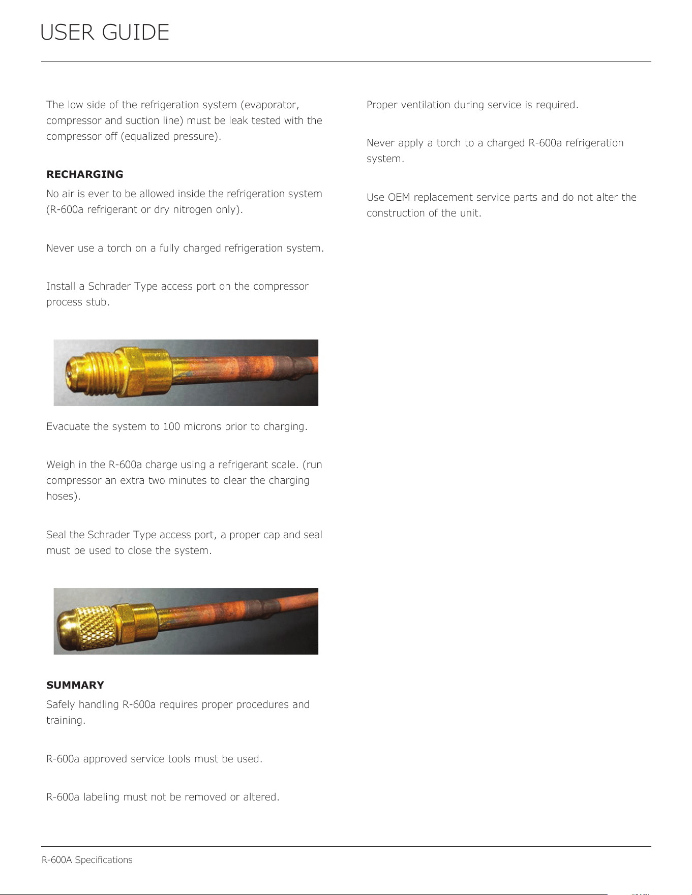
Install a Schrader Type access port on the compressor
process stub.
Evacuate the system to 100 microns prior to charging.
Weigh in the R-600a charge using a refrigerant scale. (run
compressor an extra two minutes to clear the charging
hoses).
Seal the Schrader Type access port, a proper cap and seal
must be used to close the system.
SUMMARY
Safely handling R-600a requires proper procedures and
training.
R-600a approved service tools must be used.
R-600a labeling must not be removed or altered.
Proper ventilation during service is required.
Never apply a torch to a charged R-600a refrigeration
system.
Use OEM replacement service parts and do not alter the
construction of the unit.
36
USER GUIDE
System Diagnosis Guide
System Diagnosis Guide
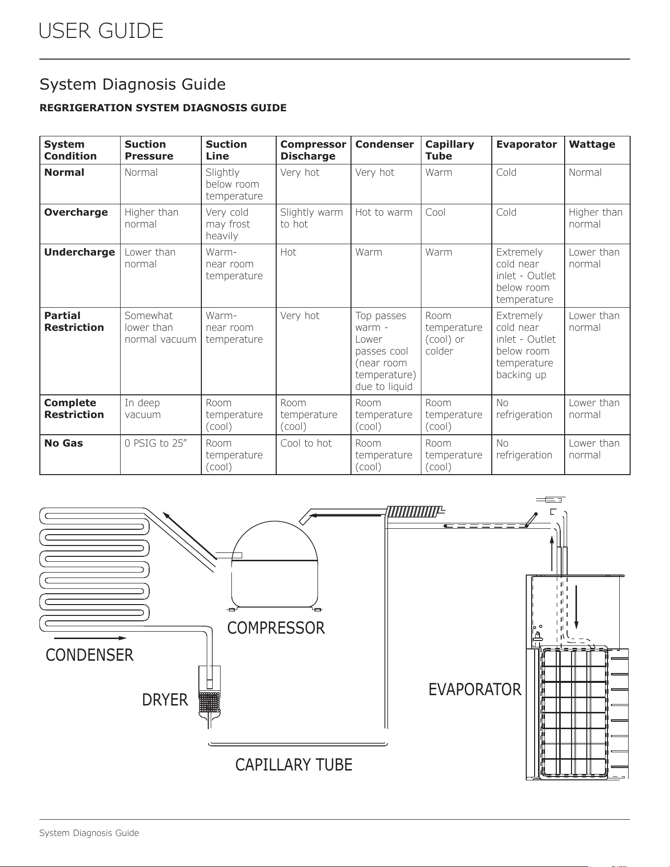
REGRIGERATION SYSTEM DIAGNOSIS GUIDE
System
Condition
Suction
Pressure
Suction
Line
Compressor
Discharge
Condenser Capillary
Tube
Evaporator Wattage
Normal Normal Slightly
below room
temperature
Very hot Very hot Warm Cold Normal
Overcharge Higher than
normal
Very cold
may frost
heavily
Slightly warm
to hot
Hot to warm Cool Cold Higher than
normal
Undercharge Lower than
normal
Warm-
near room
temperature
Hot Warm Warm Extremely
cold near
inlet - Outlet
below room
temperature
Lower than
normal
Partial
Restriction
Somewhat
lower than
normal vacuum
Warm-
near room
temperature
Very hot Top passes
warm -
Lower
passes cool
(near room
temperature)
due to liquid
Room
temperature
(cool) or
colder
Extremely
cold near
inlet - Outlet
below room
temperature
backing up
Lower than
normal
Complete
Restriction
In deep
vacuum
Room
temperature
(cool)
Room
temperature
(cool)
Room
temperature
(cool)
Room
temperature
(cool)
No
refrigeration
Lower than
normal
No Gas 0 PSIG to 25” Room
temperature
(cool)
Cool to hot Room
temperature
(cool)
Room
temperature
(cool)
No
refrigeration
Lower than
normal
CAPILLARY TUBE
DRYER
CONDENSER
COMPRESSOR
EVAPORATOR
37
USER GUIDE
Compressor Specications
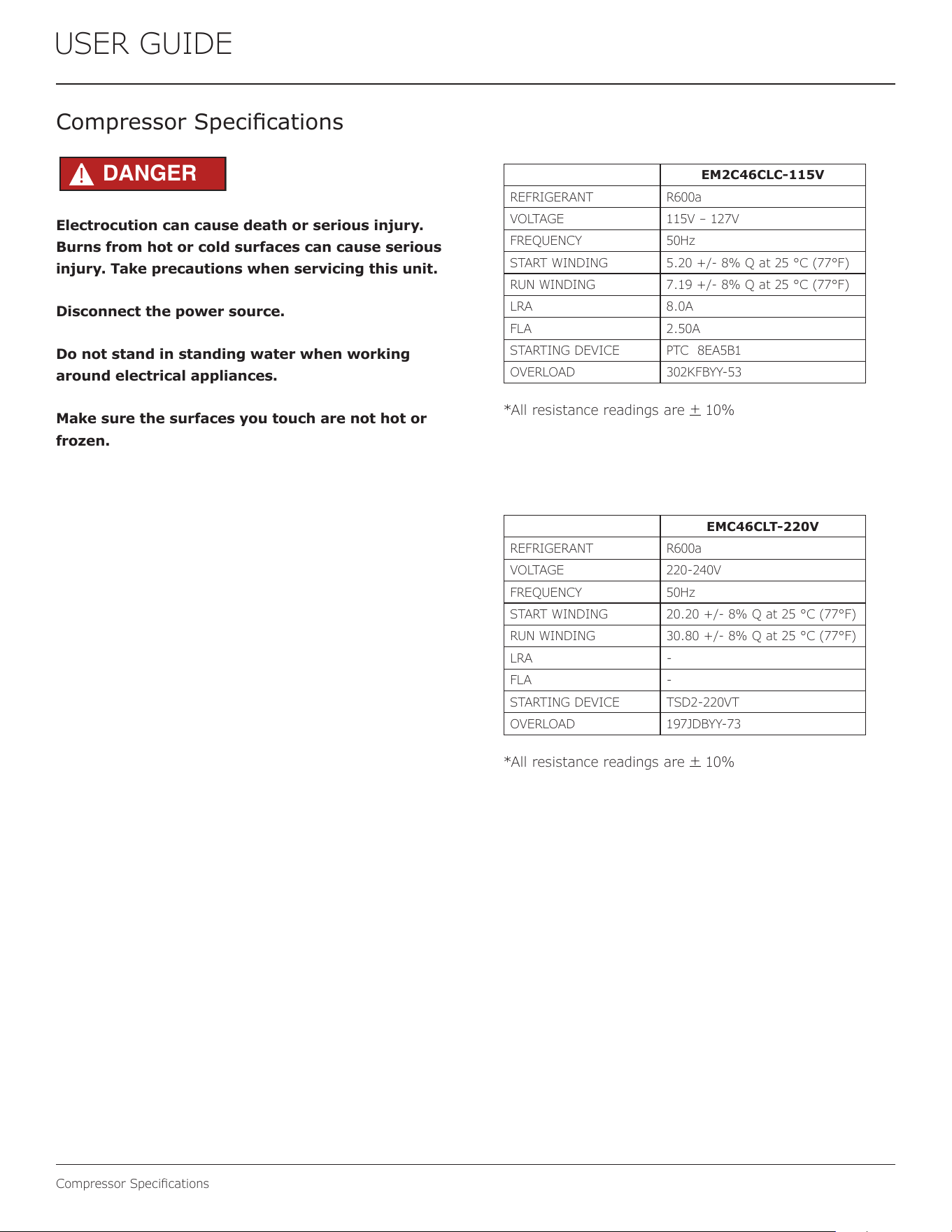
Electrocution can cause death or serious injury.
Burns from hot or cold surfaces can cause serious
injury. Take precautions when servicing this unit.
Disconnect the power source.
Do not stand in standing water when working
around electrical appliances.
Make sure the surfaces you touch are not hot or
frozen.
Compressor Specications
EM2C46CLC-115V
REFRIGERANT R600a
VOLTAGE 115V – 127V
FREQUENCY 50Hz
START WINDING 5.20 +/- 8% Q at 25 °C (77°F)
RUN WINDING 7.19 +/- 8% Q at 25 °C (77°F)
LRA 8.0A
FLA 2.50A
STARTING DEVICE PTC 8EA5B1
OVERLOAD 302KFBYY-53
*All resistance readings are
+
10%
DANGER
!
EMC46CLT-220V
REFRIGERANT R600a
VOLTAGE 220-240V
FREQUENCY 50Hz
START WINDING 20.20 +/- 8% Q at 25 °C (77°F)
RUN WINDING 30.80 +/- 8% Q at 25 °C (77°F)
LRA -
FLA -
STARTING DEVICE TSD2-220VT
OVERLOAD 197JDBYY-73
*All resistance readings are
+
10%
38
USER GUIDE
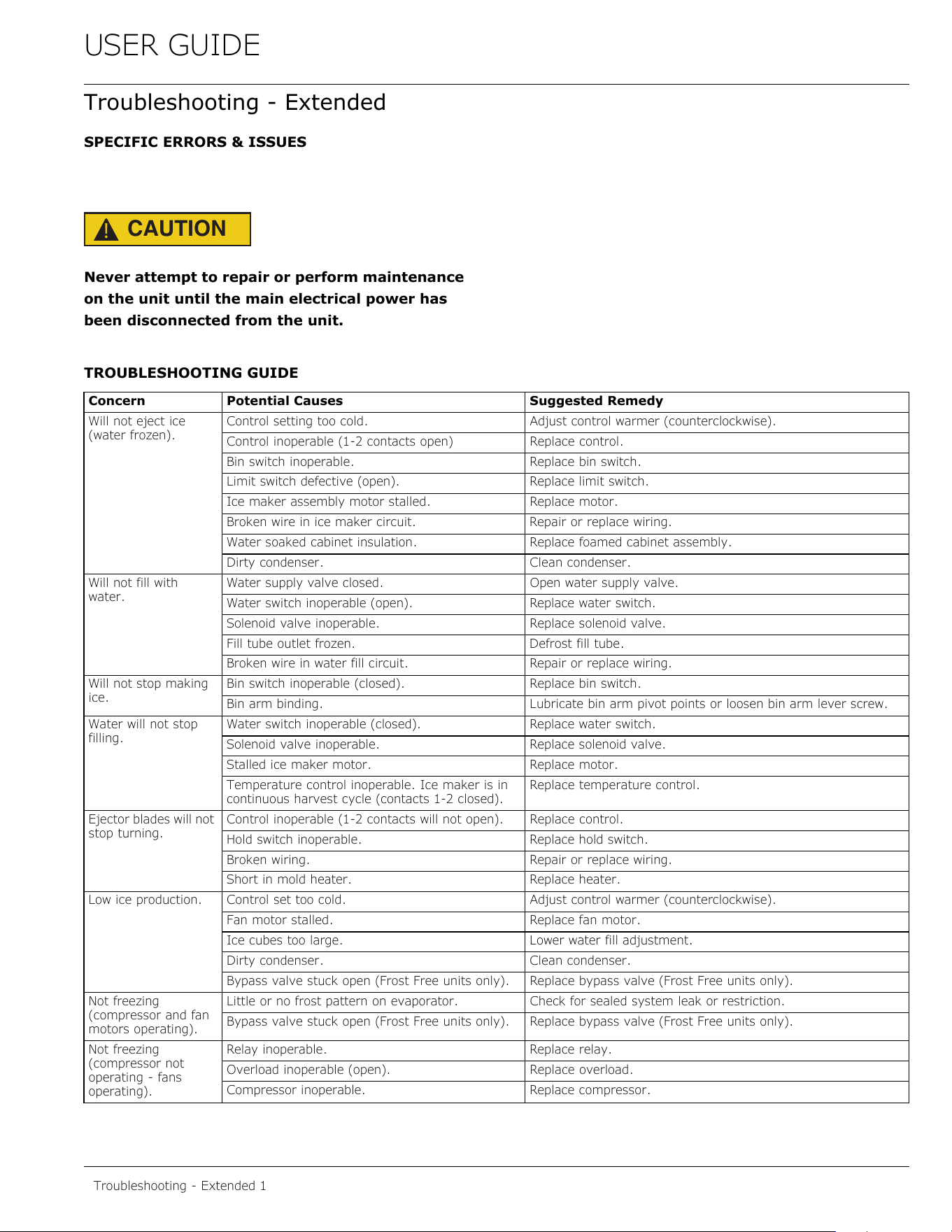
Troubleshooting - Extended
SPECIFIC ERRORS & ISSUES
CAUTION
!
Never attempt to repair or perform maintenance
on the unit until the main electrical power has
been disconnected from the unit.
TROUBLESHOOTING GUIDE
Concern Potential Causes Suggested Remedy
Will not eject ice
(water frozen).
Control setting too cold. Adjust control warmer (counterclockwise).
Control inoperable (1-2 contacts open) Replace control.
Bin switch inoperable. Replace bin switch.
Limit switch defective (open). Replace limit switch.
Ice maker assembly motor stalled. Replace motor.
Broken wire in ice maker circuit. Repair or replace wiring.
Water soaked cabinet insulation. Replace foamed cabinet assembly.
Dirty condenser. Clean condenser.
Will not fill with
water.
Water supply valve closed. Open water supply valve.
Water switch inoperable (open). Replace water switch.
Solenoid valve inoperable. Replace solenoid valve.
Fill tube outlet frozen. Defrost fill tube.
Broken wire in water fill circuit. Repair or replace wiring.
Will not stop making
ice.
Bin switch inoperable (closed). Replace bin switch.
Bin arm binding. Lubricate bin arm pivot points or loosen bin arm lever screw.
Water will not stop
filling.
Water switch inoperable (closed). Replace water switch.
Solenoid valve inoperable. Replace solenoid valve.
Stalled ice maker motor. Replace motor.
Temperature control inoperable. Ice maker is in
continuous harvest cycle (contacts 1-2 closed).
Replace temperature control.
Ejector blades will not
stop turning.
Control inoperable (1-2 contacts will not open). Replace control.
Hold switch inoperable. Replace hold switch.
Broken wiring. Repair or replace wiring.
Short in mold heater. Replace heater.
Low ice production. Control set too cold. Adjust control warmer (counterclockwise).
Fan motor stalled. Replace fan motor.
Ice cubes too large. Lower water fill adjustment.
Dirty condenser. Clean condenser.
Bypass valve stuck open (Frost Free units only). Replace bypass valve (Frost Free units only).
Not freezing
(compressor and fan
motors operating).
Little or no frost pattern on evaporator. Check for sealed system leak or restriction.
Bypass valve stuck open (Frost Free units only). Replace bypass valve (Frost Free units only).
Not freezing
(compressor not
operating - fans
operating).
Relay inoperable. Replace relay.
Overload inoperable (open). Replace overload.
Compressor inoperable. Replace compressor.
Troubleshooting - Extended 1
39
USER GUIDE
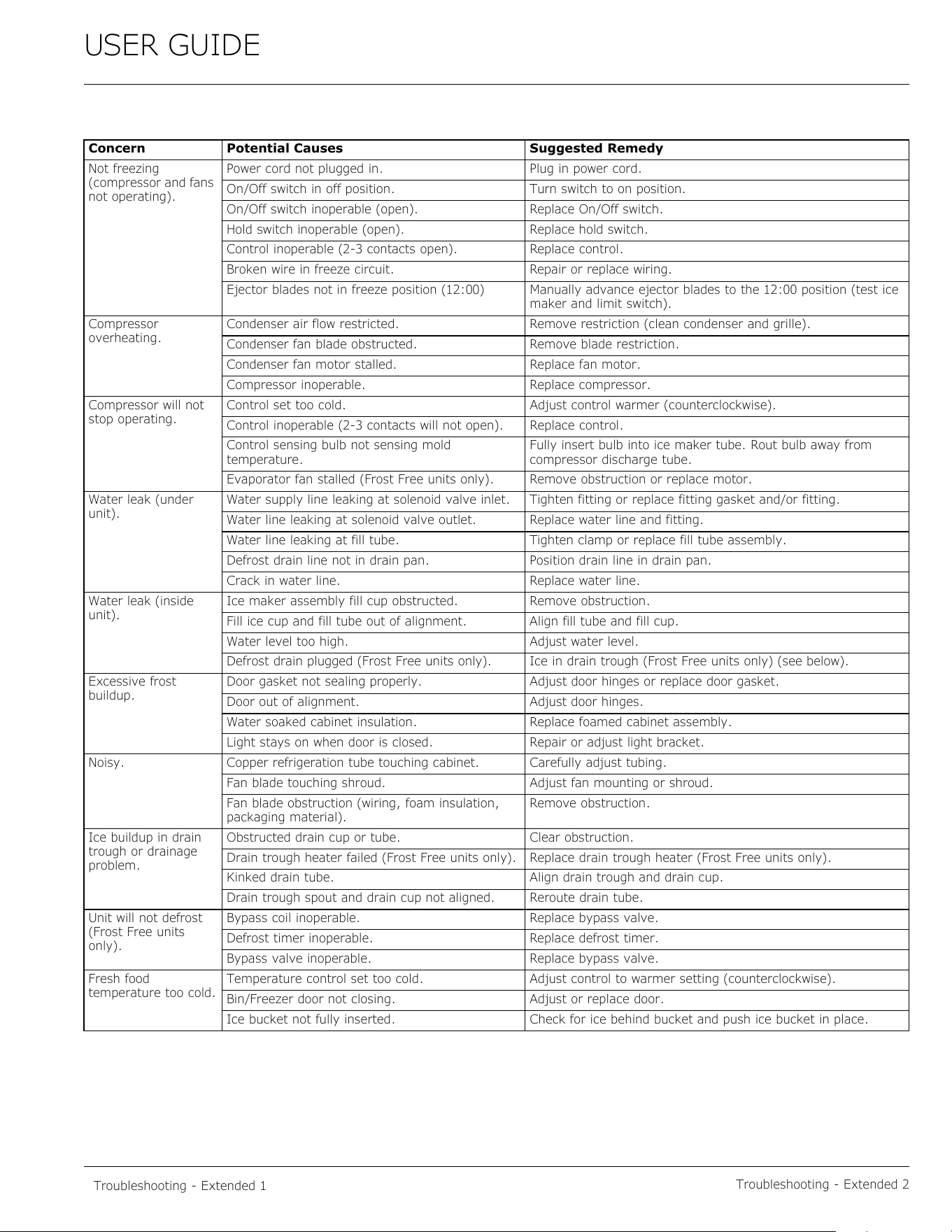
Troubleshooting - Extended 2
Not freezing
(compressor and fans
not operating).
Power cord not plugged in. Plug in power cord.
On/Off switch in off position. Turn switch to on position.
On/Off switch inoperable (open). Replace On/Off switch.
Hold switch inoperable (open). Replace hold switch.
Control inoperable (2-3 contacts open). Replace control.
Broken wire in freeze circuit. Repair or replace wiring.
Ejector blades not in freeze position (12:00) Manually advance ejector blades to the 12:00 position (test ice
maker and limit switch).
Compressor
overheating.
Condenser air flow restricted. Remove restriction (clean condenser and grille).
Condenser fan blade obstructed. Remove blade restriction.
Condenser fan motor stalled. Replace fan motor.
Compressor inoperable. Replace compressor.
Compressor will not
stop operating.
Control set too cold. Adjust control warmer (counterclockwise).
Control inoperable (2-3 contacts will not open). Replace control.
Control sensing bulb not sensing mold
temperature.
Fully insert bulb into ice maker tube. Rout bulb away from
compressor discharge tube.
Evaporator fan stalled (Frost Free units only). Remove obstruction or replace motor.
Water leak (under
unit).
Water supply line leaking at solenoid valve inlet. Tighten fitting or replace fitting gasket and/or fitting.
Water line leaking at solenoid valve outlet. Replace water line and fitting.
Water line leaking at fill tube. Tighten clamp or replace fill tube assembly.
Defrost drain line not in drain pan. Position drain line in drain pan.
Crack in water line. Replace water line.
Water leak (inside
unit).
Ice maker assembly fill cup obstructed. Remove obstruction.
Fill ice cup and fill tube out of alignment. Align fill tube and fill cup.
Water level too high. Adjust water level.
Defrost drain plugged (Frost Free units only). Ice in drain trough (Frost Free units only) (see below).
Excessive frost
buildup.
Door gasket not sealing properly. Adjust door hinges or replace door gasket.
Door out of alignment. Adjust door hinges.
Water soaked cabinet insulation. Replace foamed cabinet assembly.
Light stays on when door is closed. Repair or adjust light bracket.
Noisy. Copper refrigeration tube touching cabinet. Carefully adjust tubing.
Fan blade touching shroud. Adjust fan mounting or shroud.
Fan blade obstruction (wiring, foam insulation,
packaging material).
Remove obstruction.
Ice buildup in drain
trough or drainage
problem.
Obstructed drain cup or tube. Clear obstruction.
Drain trough heater failed (Frost Free units only). Replace drain trough heater (Frost Free units only).
Kinked drain tube. Align drain trough and drain cup.
Drain trough spout and drain cup not aligned. Reroute drain tube.
Unit will not defrost
(Frost Free units
only).
Bypass coil inoperable. Replace bypass valve.
Defrost timer inoperable. Replace defrost timer.
Bypass valve inoperable. Replace bypass valve.
Fresh food
temperature too cold.
Temperature control set too cold. Adjust control to warmer setting (counterclockwise).
Bin/Freezer door not closing. Adjust or replace door.
Ice bucket not fully inserted. Check for ice behind bucket and push ice bucket in place.
Concern Potential Causes Suggested Remedy
Troubleshooting - Extended 1
40
USER GUIDE
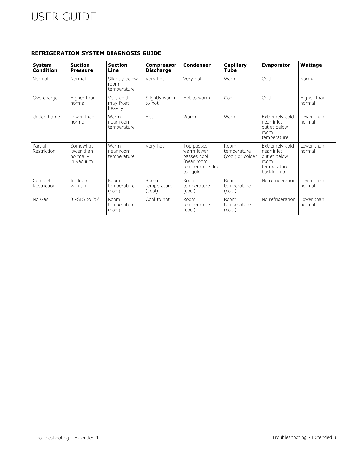
Troubleshooting - Extended 3
REFRIGERATION SYSTEM DIAGNOSIS GUIDE
System
Condition
Suction
Pressure
Suction
Line
Compressor
Discharge
Condenser Capillary
Tube
Evaporator Wattage
Normal Normal Slightly below
room
temperature
Very hot Very hot Warm Cold Normal
Overcharge Higher than
normal
Very cold -
may frost
heavily
Slightly warm
to hot
Hot to warm Cool Cold Higher than
normal
Undercharge Lower than
normal
Warm -
near room
temperature
Hot Warm Warm Extremely cold
near inlet -
outlet below
room
temperature
Lower than
normal
Partial
Restriction
Somewhat
lower than
normal -
in vacuum
Warm -
near room
temperature
Very hot Top passes
warm lower
passes cool
(near room
temperature due
to liquid
Room
temperature
(cool) or colder
Extremely cold
near inlet -
outlet below
room
temperature
backing up
Lower than
normal
Complete
Restriction
In deep
vacuum
Room
temperature
(cool)
Room
temperature
(cool)
Room
temperature
(cool)
Room
temperature
(cool)
No refrigeration Lower than
normal
No Gas 0 PSIG to 25" Room
temperature
(cool)
Cool to hot Room
temperature
(cool)
Room
temperature
(cool)
No refrigeration Lower than
normal
Troubleshooting - Extended 1
41
USER GUIDE
Troubleshooting - Extended 4
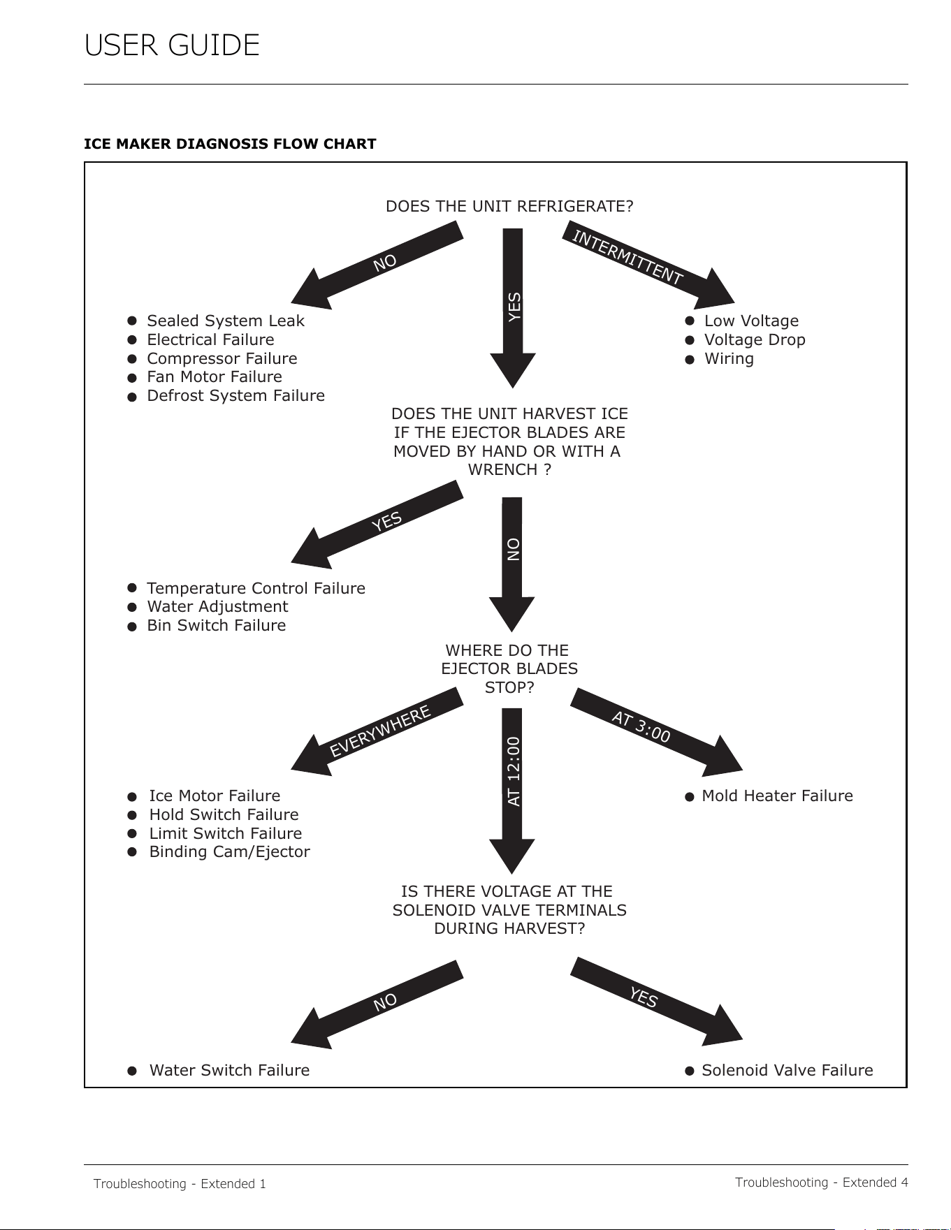
ICE MAKER DIAGNOSIS FLOW CHART
DOES THE UNIT REFRIGERATE?
Sealed System Leak
Electrical Failure
Compressor Failure
Fan Motor Failure
Defrost System Failure
Low Voltage
Voltage Drop
Wiring
Temperature Control Failure
Water Adjustment
Bin Switch Failure
NO
NO
EVERYWHERE
INTERMITTENT
AT 3:00
YES
NO
AT 12:00
DOES THE UNIT HARVEST ICE
IF THE EJECTOR BLADES ARE
MOVED BY HAND OR WITH A
WRENCH ?
WHERE DO THE
EJECTOR BLADES
STOP?
Mold Heater Failure
Solenoid Valve Failure
Ice Motor Failure
Hold Switch Failure
Limit Switch Failure
Binding Cam/Ejector
Water Switch Failure
IS THERE VOLTAGE AT THE
SOLENOID VALVE TERMINALS
DURING HARVEST?
YES
YES
Troubleshooting - Extended 1
42
USER GUIDE
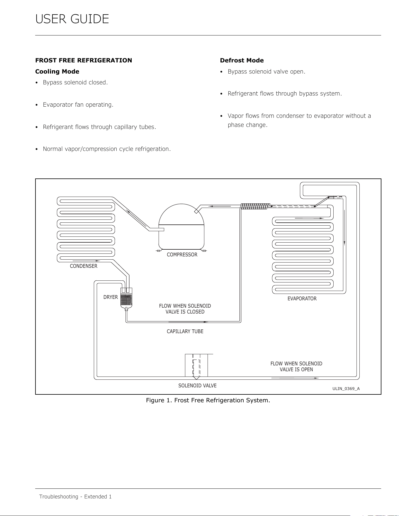
FROST FREE REFRIGERATION
Cooling Mode
• Bypass solenoid closed.
• Evaporator fan operating.
• Refrigerant flows through capillary tubes.
• Normal vapor/compression cycle refrigeration.
Defrost Mode
• Bypass solenoid valve open.
• Refrigerant flows through bypass system.
• Vapor flows from condenser to evaporator without a
phase change.
Figure 1. Frost Free Refrigeration System.
SOLENOID VALVE
CAPILLARY TUBE
VALVE IS CLOSED
FLOW WHEN SOLENOID
DRYER
CONDENSER
COMPRESSOR
EVAPORATOR
VALVE IS OPEN
FLOW WHEN SOLENOID
ULIN_0369_A
Troubleshooting - Extended 1
43
USER GUIDE
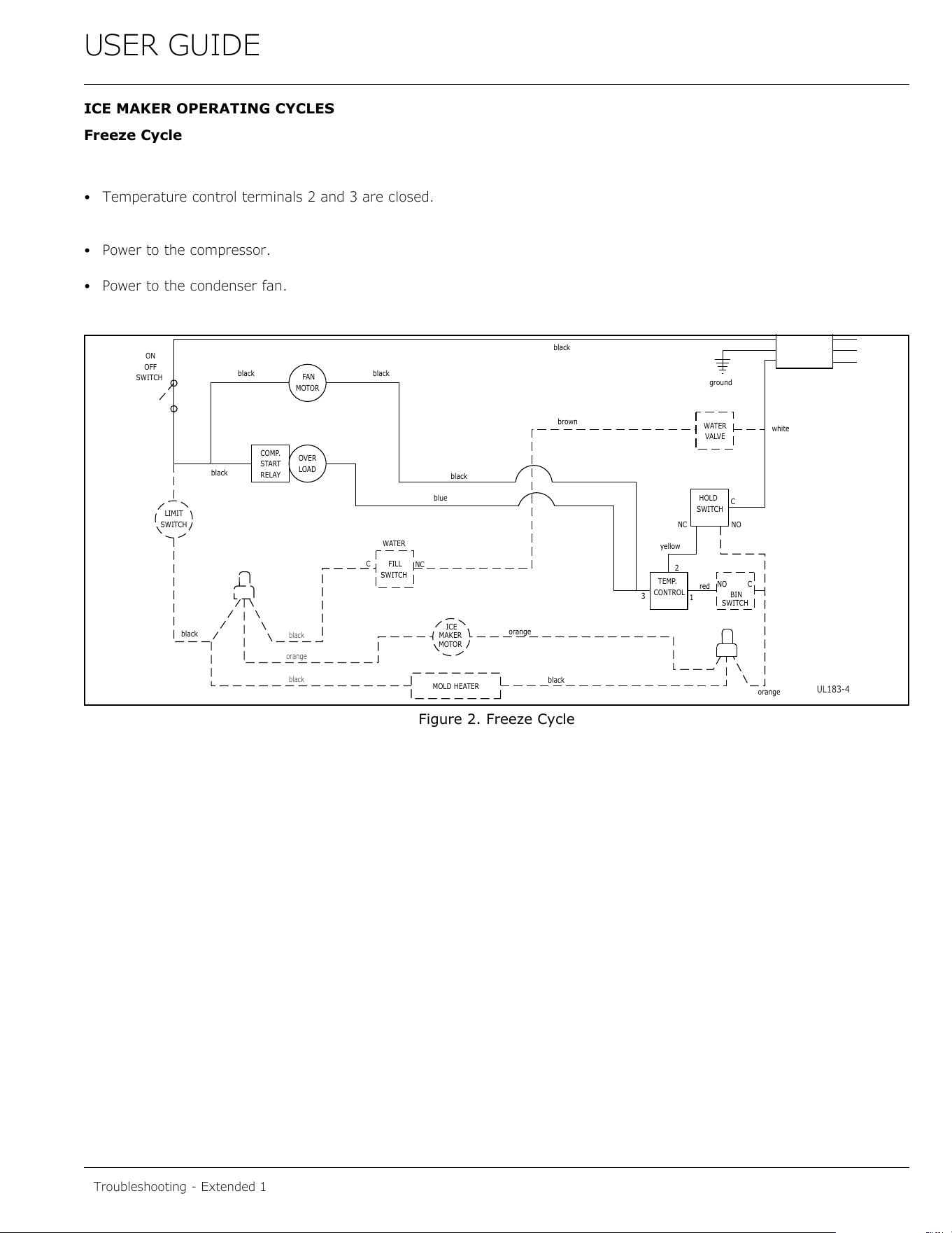
ICE MAKER OPERATING CYCLES
Freeze Cycle
• Temperature control terminals 2 and 3 are closed.
• Power to the compressor.
• Power to the condenser fan.
Figure 2. Freeze Cycle
SWITCH
LIMIT
orange
black
black
black
MOTOR
MAKER
ICE
MOLD HEATER
WATER
SWITCH
FILL
C
NC
MOTOR
FAN
LOAD
OVER
black
RELAY
START
COMP.
SWITCH
OFF
ON
black
black
blue
black
CONTROL
TEMP.
NC
black
orange
3
yellow
2
orange
SWITCH
BIN
red
NO
1
C
NO
brown
black
white
C
SWITCH
HOLD
VALVE
WATER
ground
UL183-4
Troubleshooting - Extended 1
44
USER GUIDE
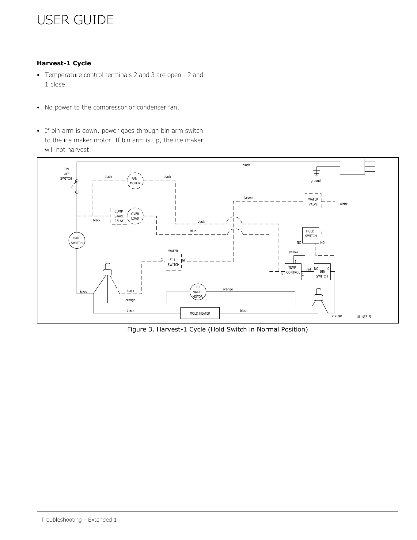
Harvest-1 Cycle
• Temperature control terminals 2 and 3 are open - 2 and
1 close.
• No power to the compressor or condenser fan.
• If bin arm is down, power goes through bin arm switch
to the ice maker motor. If bin arm is up, the ice maker
will not harvest.
Figure 3. Harvest-1 Cycle (Hold Switch in Normal Position)
SWITCH
LIMIT
orange
black
black
black
MOTOR
MAKER
ICE
MOLD HEATER
WATER
SWITCH
FILL
C
NC
MOTOR
FAN
LOAD
OVER
black
RELAY
START
COMP.
SWITCH
OFF
ON
black
black
blue
black
CONTROL
TEMP.
NC
black
orange
3
yellow
2
orange
SWITCH
BIN
red
NO
1
C
NO
brown
black
white
C
SWITCH
HOLD
VALVE
WATER
ground
UL183-5
Troubleshooting - Extended 1
45
USER GUIDE
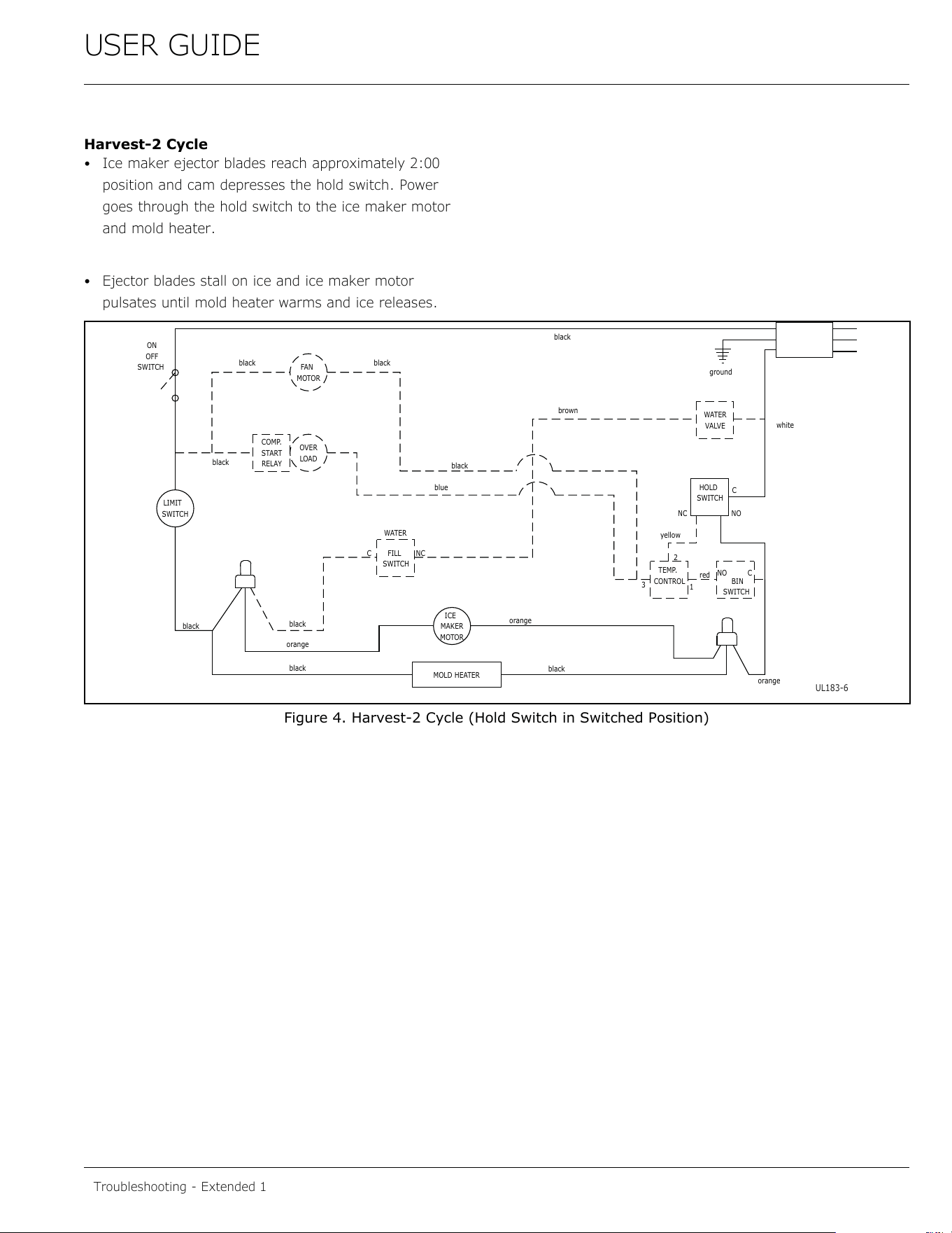
Harvest-2 Cycle
• Ice maker ejector blades reach approximately 2:00
position and cam depresses the hold switch. Power
goes through the hold switch to the ice maker motor
and mold heater.
• Ejector blades stall on ice and ice maker motor
pulsates until mold heater warms and ice releases.
Figure 4. Harvest-2 Cycle (Hold Switch in Switched Position)
SWITCH
LIMIT
orange
black
black
black
MOTOR
MAKER
ICE
MOLD HEATER
WATER
SWITCH
FILL
C
NC
MOTOR
FAN
LOAD
OVER
black
RELAY
START
COMP.
SWITCH
OFF
ON
black
black
blue
black
CONTROL
TEMP.
NC
black
orange
3
yellow
2
orange
SWITCH
BIN
red
NO
1
C
NO
brown
black
white
C
SWITCH
HOLD
VALVE
WATER
ground
UL183-6
Troubleshooting - Extended 1
46
USER GUIDE
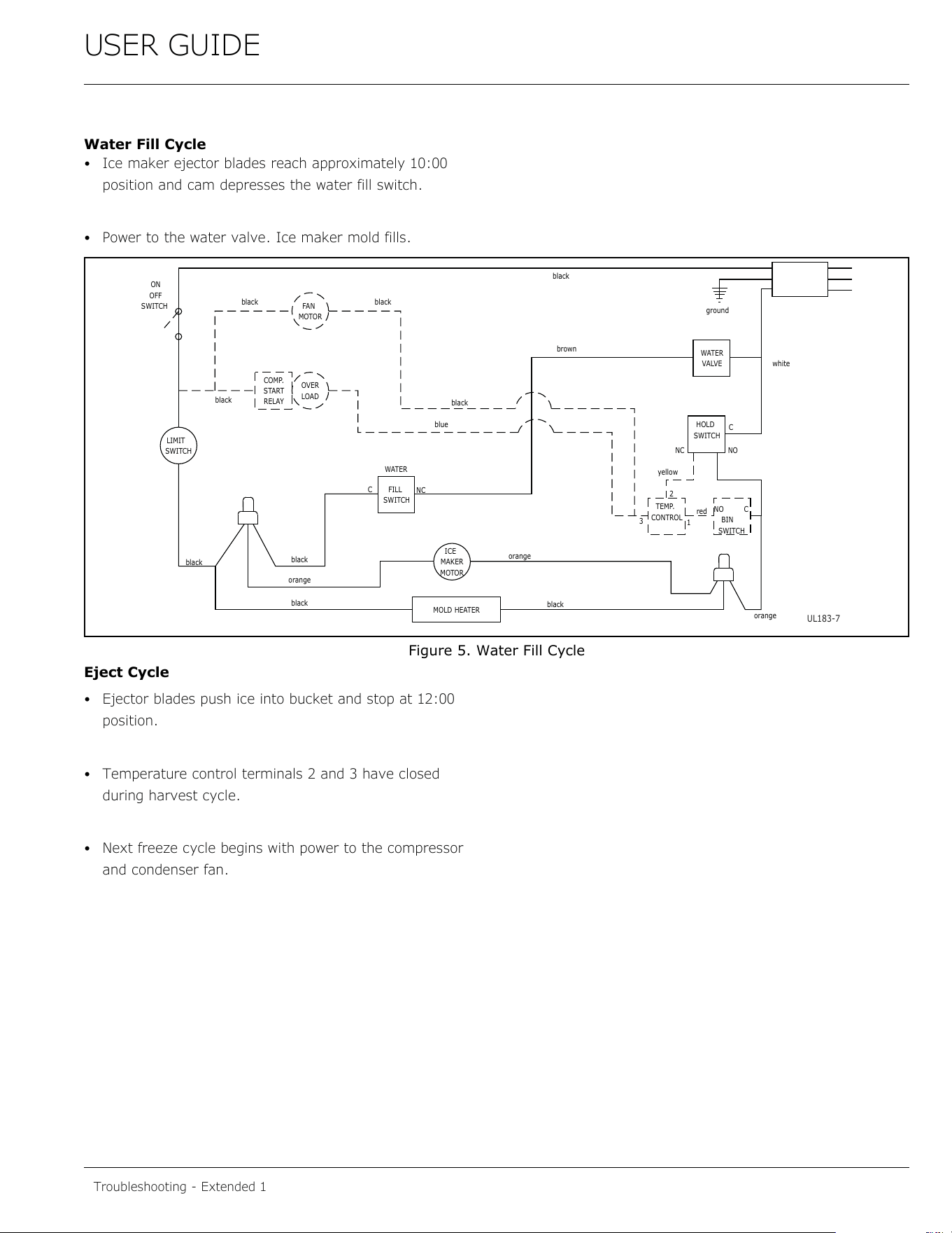
Water Fill Cycle
• Ice maker ejector blades reach approximately 10:00
position and cam depresses the water fill switch.
• Power to the water valve. Ice maker mold fills.
Figure 5. Water Fill Cycle
Eject Cycle
• Ejector blades push ice into bucket and stop at 12:00
position.
• Temperature control terminals 2 and 3 have closed
during harvest cycle.
• Next freeze cycle begins with power to the compressor
and condenser fan.
SWITCH
LIMIT
orange
black
black
black
MOTOR
MAKER
ICE
MOLD HEATER
WATER
SWITCH
FILL
C
NC
MOTOR
FAN
LOAD
OVER
black
RELAY
START
COMP.
SWITCH
OFF
ON
black
black
blue
black
CONTROL
TEMP.
NC
black
orange
3
yellow
2
orange
SWITCH
BIN
red
NO
1
C
NO
brown
black
white
C
SWITCH
HOLD
VALVE
WATER
ground
UL183-7
Troubleshooting - Extended 1
47
USER GUIDE
ICE MAKER OPERATING CYCLES (U-CO29F
MODEL)
NOTE: The refrigeration system operates independently of
the ice maker. This is a new design for U-Line. All other
U-Line ice makers use a double throw control system
where the unit is either in a freeze mode or harvest mode.
In the U-CO29F, the refrigeration system will cycle on and
off depending on the temperature of the freezer. In most
cases, this means the refrigeration system will be
operating during the ice making and harvest modes. If the
freezer control is set too warm, the refrigeration system
may cycle off during ice making mode, slowing the ice
production rate. If this happens, adjust the freezer control
colder.
Freeze Cycle
• Ice maker thermostat (located behind grille) open.
• Freezer control closed and refrigeration system is
operating.
Harvest Cycle - 1
• Ice maker thermostat closed.
• Refrigeration system operating.
• If bin arm is up, the harvest will not initiate.
• Power goes through the bin switch to the ice maker
motor and mold heater.
Harvest Cycle - 2
• Ice maker ejector blades reach 2:00 position and cam
depresses the hold switch.
• Ejector blades stall on ice and ice maker motor
pulsates until mold heater warms and ice releases.
• Refrigeration system operating.
Water Fill Cycle
• Ice maker blades reach approximately 10:00 position
and cam depresses the water fill switch.
• Power to the water valve. Ice maker mold fills.
• Refrigeration system operating.
Eject Cycle
• Ejector blades push ice into bucket and stop at 12:00
position.
• Ice maker temperature control opens.
• Refrigeration system still operating.
Troubleshooting - Extended 1
48
USER GUIDE
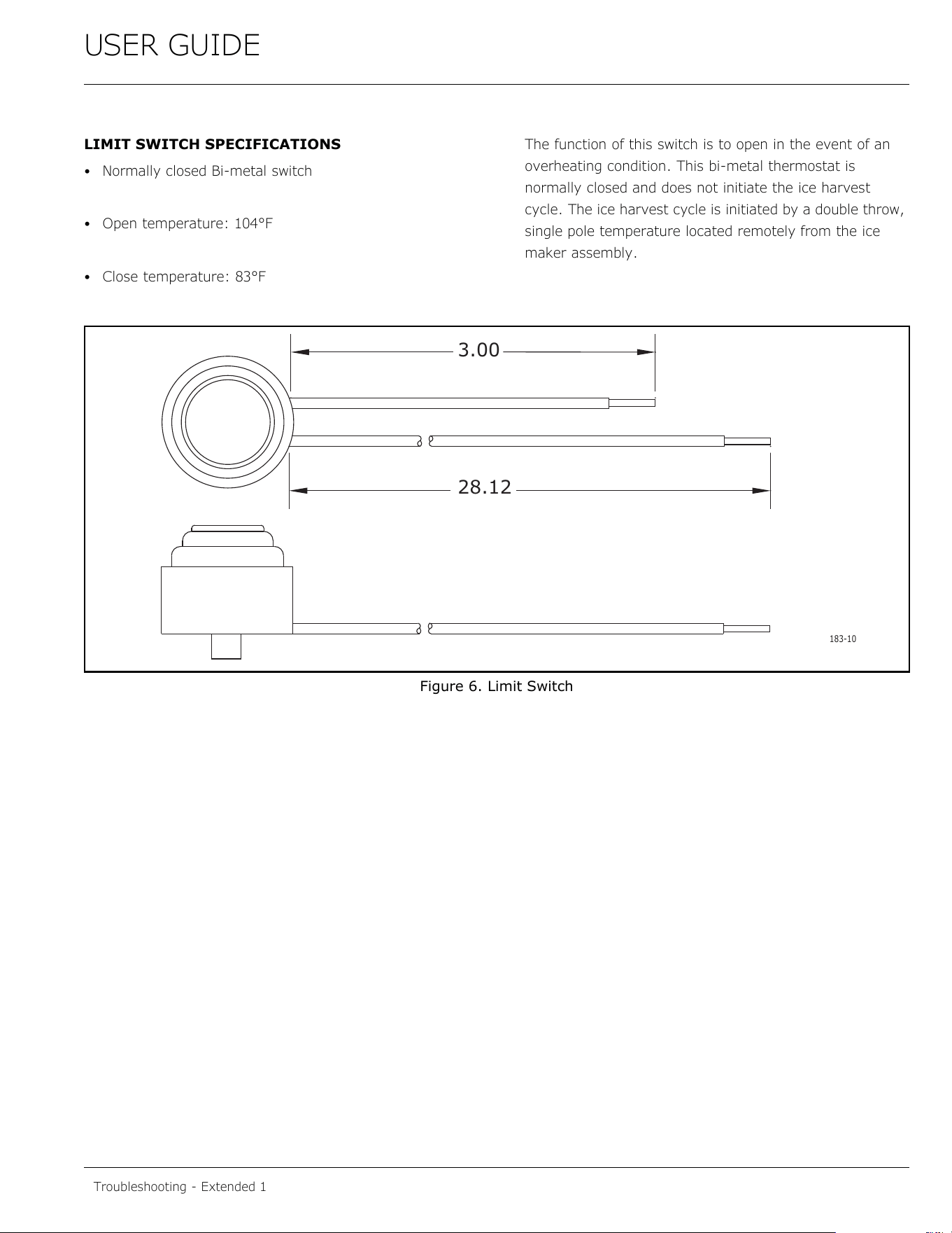
LIMIT SWITCH SPECIFICATIONS
• Normally closed Bi-metal switch
• Open temperature: 104°F
• Close temperature: 83°F
The function of this switch is to open in the event of an
overheating condition. This bi-metal thermostat is
normally closed and does not initiate the ice harvest
cycle. The ice harvest cycle is initiated by a double throw,
single pole temperature located remotely from the ice
maker assembly.
Figure 6. Limit Switch
28.12
3.00
183-10
Troubleshooting - Extended 1
49
USER GUIDE
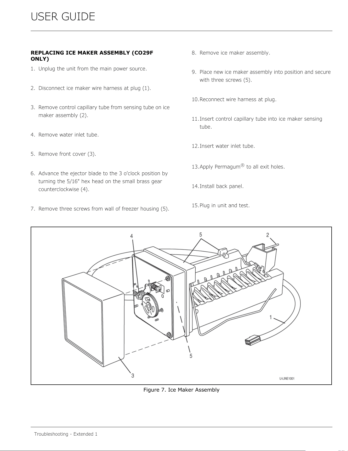
REPLACING ICE MAKER ASSEMBLY (CO29F
ONLY)
1. Unplug the unit from the main power source.
2. Disconnect ice maker wire harness at plug (1).
3. Remove control capillary tube from sensing tube on ice
maker assembly (2).
4. Remove water inlet tube.
5. Remove front cover (3).
6. Advance the ejector blade to the 3 o’clock position by
turning the 5/16" hex head on the small brass gear
counterclockwise (4).
7. Remove three screws from wall of freezer housing (5).
8. Remove ice maker assembly.
9. Place new ice maker assembly into position and secure
with three screws (5).
10.Reconnect wire harness at plug.
11.Insert control capillary tube into ice maker sensing
tube.
12.Insert water inlet tube.
13.Apply Permagum
®
to all exit holes.
14.Install back panel.
15.Plug in unit and test.
Figure 7. Ice Maker Assembly
Troubleshooting - Extended 1
50
USER GUIDE
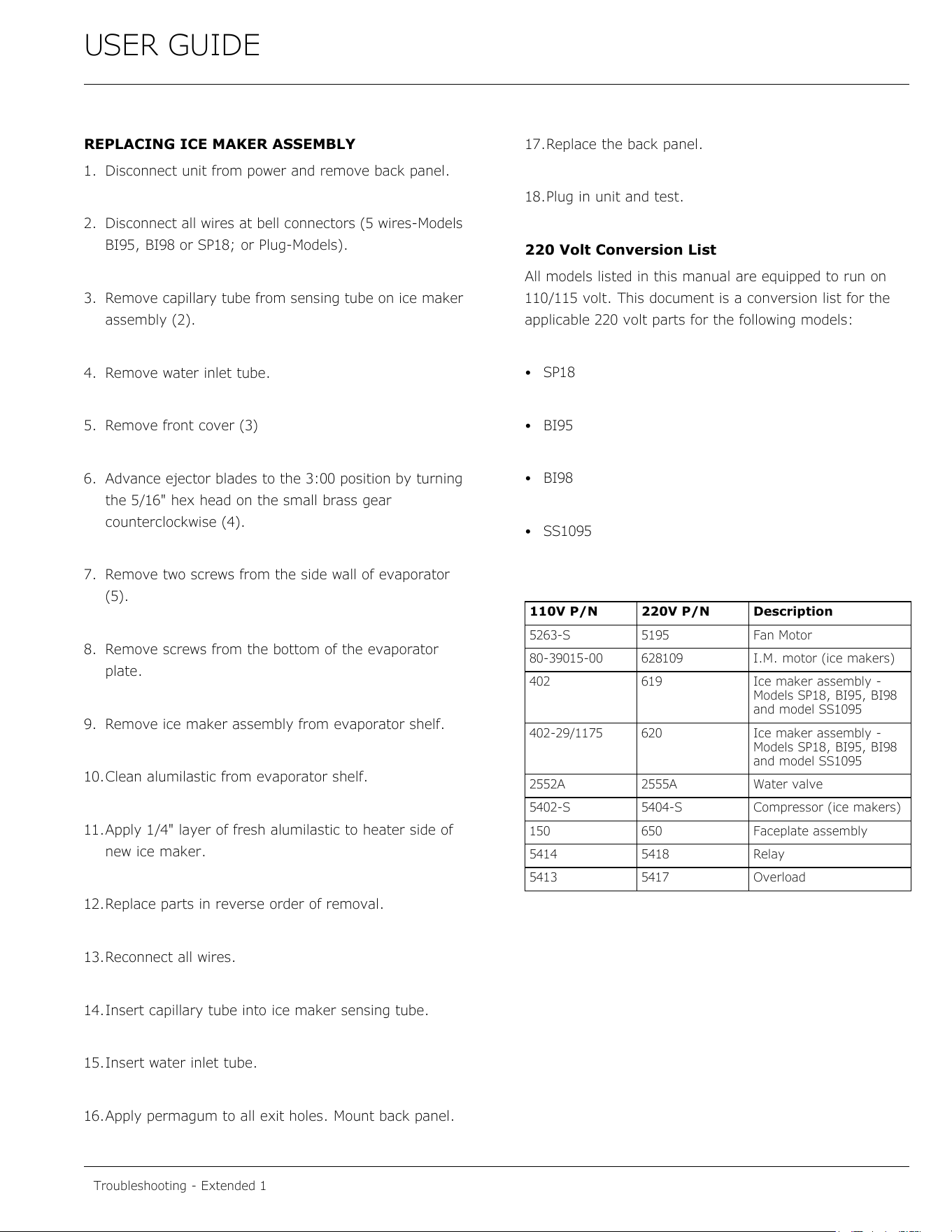
REPLACING ICE MAKER ASSEMBLY
1. Disconnect unit from power and remove back panel.
2. Disconnect all wires at bell connectors (5 wires-Models
BI95, BI98 or SP18; or Plug-Models).
3. Remove capillary tube from sensing tube on ice maker
assembly (2).
4. Remove water inlet tube.
5. Remove front cover (3)
6. Advance ejector blades to the 3:00 position by turning
the 5/16" hex head on the small brass gear
counterclockwise (4).
7. Remove two screws from the side wall of evaporator
(5).
8. Remove screws from the bottom of the evaporator
plate.
9. Remove ice maker assembly from evaporator shelf.
10.Clean alumilastic from evaporator shelf.
11.Apply 1/4" layer of fresh alumilastic to heater side of
new ice maker.
12.Replace parts in reverse order of removal.
13.Reconnect all wires.
14.Insert capillary tube into ice maker sensing tube.
15.Insert water inlet tube.
16.Apply permagum to all exit holes. Mount back panel.
17.Replace the back panel.
18.Plug in unit and test.
220 Volt Conversion List
All models listed in this manual are equipped to run on
110/115 volt. This document is a conversion list for the
applicable 220 volt parts for the following models:
•SP18
•BI95
•BI98
• SS1095
110V P/N 220V P/N Description
5263-S 5195 Fan Motor
80-39015-00 628109 I.M. motor (ice makers)
402 619 Ice maker assembly -
Models SP18, BI95, BI98
and model SS1095
402-29/1175 620 Ice maker assembly -
Models SP18, BI95, BI98
and model SS1095
2552A 2555A Water valve
5402-S 5404-S Compressor (ice makers)
150 650 Faceplate assembly
5414 5418 Relay
5413 5417 Overload
Troubleshooting - Extended 1
51
USER GUIDE
Control Operation-Service
Control Operation-Service
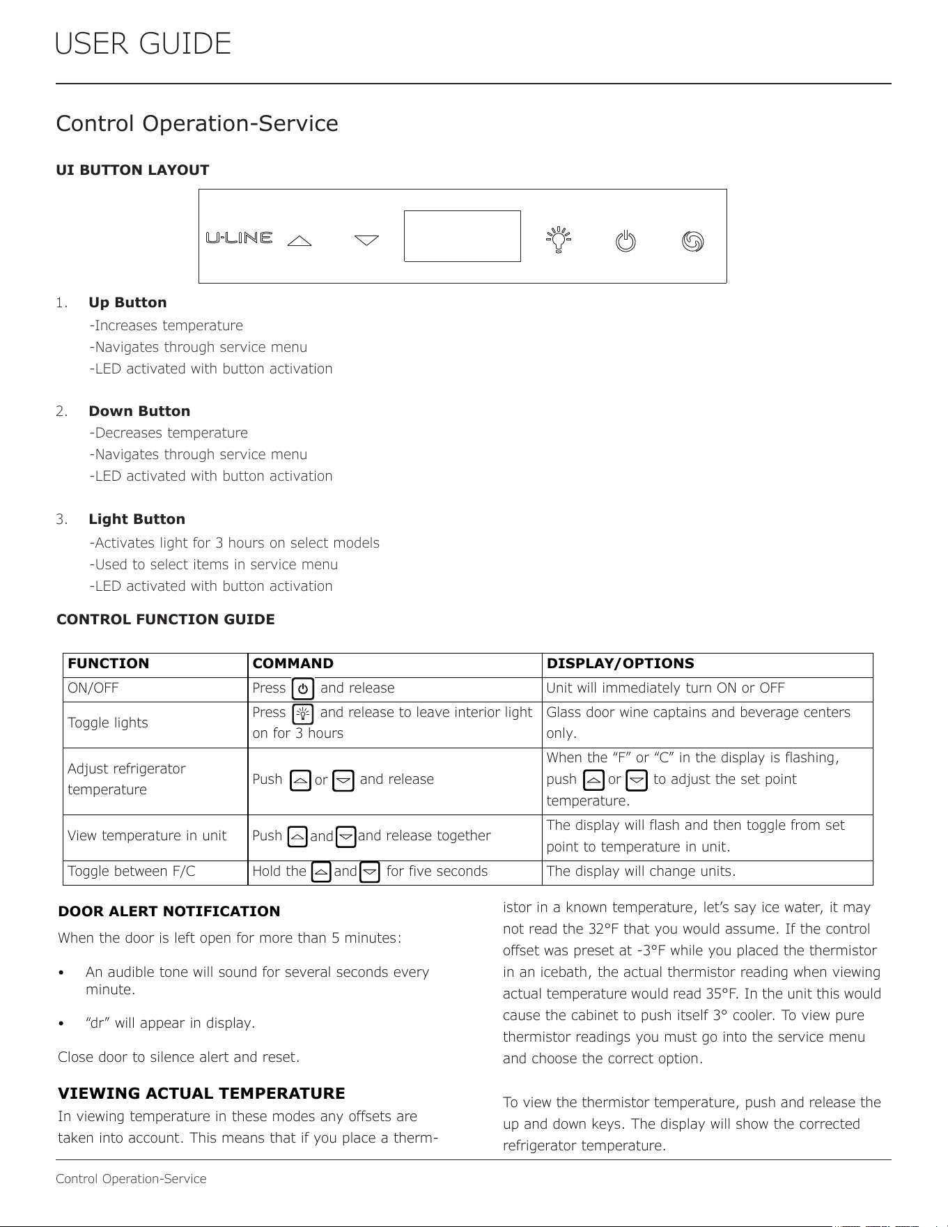
UI BUTTON LAYOUT
1. Up Button
2. Down Button
3. Light Button
-Increases temperature
-Navigates through service menu
-LED activated with button activation
-Decreases temperature
-Navigates through service menu
-LED activated with button activation
-Activates light for 3 hours on select models
-Used to select items in service menu
-LED activated with button activation
CONTROL FUNCTION GUIDE
USER GUIDE
Control Operation - Service 2
u-line.com
SAFETY • INSTALLATION & INTEGRATION • OPERATING INSTRUCTIONS • MAINTENANCE • SERVICE
DOOR ALERT NOTIFICATION
When the door is left open for more than 5 minutes:
• An audible tone will sound for several seconds every
minute.
• “dr” will appear in display.
Close door to silence alert and reset.
VIEWING ACTUAL TEMPERATURE
In viewing temperature in these modes any offsets are
taken into account. This means that if you place a therm-
istor in a known temperature, let’s say ice water, it may
not read the 32°F that you would assume. If the control
offset was preset at -3°F while you placed the thermistor
in an icebath, the actual thermistor reading when viewing
actual temperature would read 35°F. In the unit this would
cause the cabinet to push itself 3° cooler. To view pure
thermistor readings you must go into the service menu
and choose the correct option.
To view the thermistor temperature, push and release the
up and down keys. The display will show the corrected
refrigerator temperature.
SHOWROOM MODE
This mode is designed to show units in a display environ-
ment. When in this mode the only functions will be the
control and cabinet lights. The compressor, fans, etc. will
not operate. To enter/exit this mode hold the light key
and the power key for 5 seconds. The display will flash
once and beep and the degree symbol will begin to flash.
When the degree symbol is flashing the unit will allow the
use of the control for demonstrations. The unit can be left
in this mode indefinitely.
SERVICE MODE
This mode has options available for service diagnostics.
To enter the mode hold the hidden key for 10 seconds.
The display will show “0.” When in this mode use the up
and down arrows to select the desired option. The LIGHT
key is the ENTER key and will initiate the function. If
changing a setting, you must press the LIGHT key again
to retain the changed setting. To exit the service mode
scroll to option “0” and press the LIGHT key. After five
minutes of not touching any keys the mode will also exit
automatically.
CONTROL FUNCTION QUICK GUIDE
FUNCTION COMMAND DISPLAY/OPTIONS
ON/OFF Press and release Unit will immediately turn ON or OFF
Toggle lights
Press and release to leave interior light
on for 3 hours
Glass door wine captains and beverage centers
only.
Adjust refrigerator
temperature
Push and release
When the “F” or “C” in the display is flashing,
push to adjust the set point
temperature.
View temperature in unit Push
and release together
The display will flash and then toggle from set
point to temperature in unit.
Toggle between F/C Hold the for five seconds The display will change units.
or
or
and
and
USER GUIDE
Control Operation - Service 2
u-line.com
SAFETY • INSTALLATION & INTEGRATION • OPERATING INSTRUCTIONS • MAINTENANCE • SERVICE
DOOR ALERT NOTIFICATION
When the door is left open for more than 5 minutes:
• An audible tone will sound for several seconds every
minute.
• “dr” will appear in display.
Close door to silence alert and reset.
VIEWING ACTUAL TEMPERATURE
In viewing temperature in these modes any offsets are
taken into account. This means that if you place a therm-
istor in a known temperature, let’s say ice water, it may
not read the 32°F that you would assume. If the control
offset was preset at -3°F while you placed the thermistor
in an icebath, the actual th
ermistor reading when viewing
actual temperature would read
35°F. In the unit this would
cause the cabinet to push itself 3° cooler. To view pure
thermistor readings you must go into the service menu
and choose the correct option.
To view the thermistor temper
ature, push and release the
up and down keys. The display will show the corrected
refrigerator temperature.
SHOWROOM MODE
This mode is designed to show units in a display environ-
ment. When in this mode the only functions will be the
control and cabinet lights. The compressor, fans, etc. will
not operate. To enter/exit this mode hold the light key
and the power key for 5 seconds. The display will flash
once and beep and the degree symbol will begin to flash.
When the degree symbol is flashing the unit will allow the
use of the control for demonstrations. The unit can be left
in this mode indefinitely.
SERVICE MODE
This mode has options available for service diagnostics.
To enter the mode hold the hidden key for 10 seconds.
The display will show “0.” When in this mode use the up
and down arrows to select the desired option. The LIGHT
key is the ENTER key and will initiate the function. If
changing a setting, you must press the LIGHT key again
to retain the changed setting. To exit the service mode
scroll to option “0” and press the LIGHT key. After five
minutes of not touching any keys the mode will also exit
automatically.
CONTROL FUNCTION QUICK GUIDE
FUNCTION COMMAND DISPLAY/OPTIONS
ON/OFF Press and release Unit will immediately turn ON or OFF
Toggle lights
Press and release to leave interior light
on for 3 hours
Glass door wine captains and beverage centers
only.
Adjust refrigerator
temperature
Push and release
When the “F” or “C” in the display is flashing,
push to adjust the set point
temperature.
View temperature in unit Push
and release together
The display will flash and then toggle from set
point to temperature in unit.
Toggle between F/C Hold the for five seconds The display will change units.
or
or
and
and
52
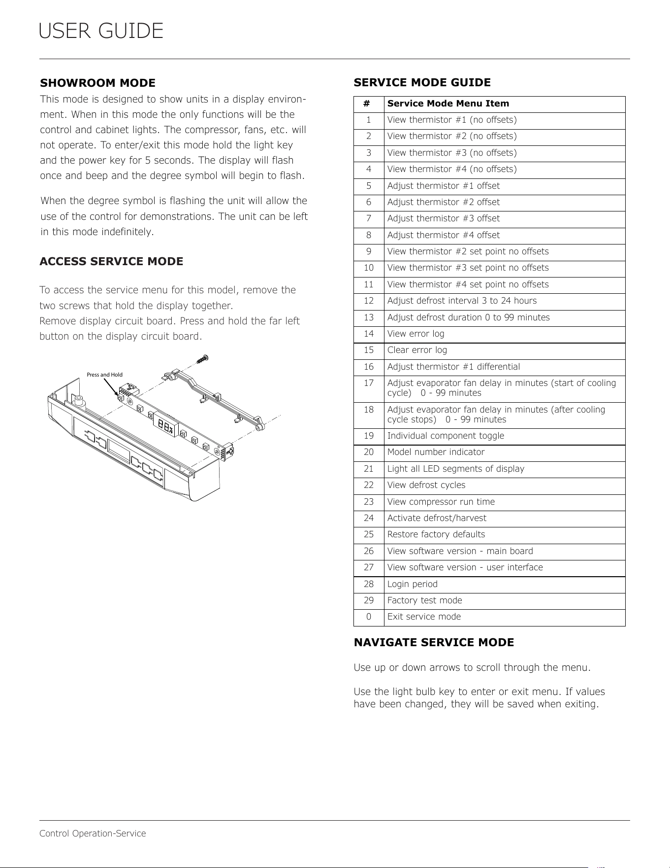
USER GUIDE
Control Operation-Service
USER GUIDE
Control Operation - Service 2
u-line.com
SAFETY • INSTALLATION & INTEGRATION • OPERATING INSTRUCTIONS • MAINTENANCE • SERVICE
DOOR ALERT NOTIFICATION
When the door is left open for more than 5 minutes:
• An audible tone will sound for several seconds every
minute.
• “dr” will appear in display.
Close door to silence alert and reset.
VIEWING ACTUAL TEMPERATURE
In viewing temperature in these modes any offsets are
taken into account. This means that if you place a therm-
istor in a known temperature, let’s say ice water, it may
not read the 32°F that you would assume. If the control
offset was preset at -3°F while you placed the thermistor
in an icebath, the actual thermistor reading when viewing
actual temperature would read 35°F. In the unit this would
cause the cabinet to push itself 3° cooler. To view pure
thermistor readings you must go into the service menu
and choose the correct option.
To view the thermistor temperature, push and release the
up and down keys. The display will show the corrected
refrigerator temperature.
SHOWROOM MODE
This mode is designed to show units in a display environ-
ment. When in this mode the only functions will be the
control and cabinet lights. The compressor, fans, etc. will
not operate. To enter/exit this mode hold the light key
and the power key for 5 seconds. The display will flash
once and beep and the degree symbol will begin to flash.
When the degree symbol is flashing the unit will allow the
use of the control for demonstrations. The unit can be left
in this mode indefinitely.
SERVICE MODE
This mode has options available for service diagnostics.
To enter the mode hold the hidden key for 10 seconds.
The display will show “0.” When in this mode use the up
and down arrows to select the desired option. The LIGHT
key is the ENTER key and will initiate the function. If
changing a setting, you must press the LIGHT key again
to retain the changed setting. To exit the service mode
scroll to option “0” and press the LIGHT key. After five
minutes of not touching any keys the mode will also exit
automatically.
CONTROL FUNCTION QUICK GUIDE
FUNCTION COMMAND DISPLAY/OPTIONS
ON/OFF Press and release Unit will immediately turn ON or OFF
Toggle lights
Press and release to leave interior light
on for 3 hours
Glass door wine captains and beverage centers
only.
Adjust refrigerator
temperature
Push and release
When the “F” or “C” in the display is flashing,
push to adjust the set point
temperature.
View temperature in unit Push
and release together
The display will flash and then toggle from set
point to temperature in unit.
Toggle between F/C Hold the for five seconds The display will change units.
or
or
and
and
USER GUIDE
Control Operation - Service 2
u-line.com
SAFETY • INSTALLATION & INTEGRATION • OPERATING INSTRUCTIONS • MAINTENANCE • SERVICE
DOOR ALERT NOTIFICATION
When the door is left open for more than 5 minutes:
• An audible tone will sound for several seconds every
minute.
• “dr” will appear in display.
Close door to silence alert and reset.
VIEWING ACTUAL TEMPERATURE
In viewing temperature in these modes any offsets are
taken into account. This means that if you place a therm-
istor in a known temperature, let’s say ice water, it may
not read the 32°F that you would assume. If the control
offset was preset at -3°F while you placed the thermistor
in an icebath, the actual thermistor reading when viewing
actual temperature would read 35°F. In the unit this would
cause the cabinet to push itself 3° cooler. To view pure
thermistor readings you must go into the service menu
and choose the correct option.
To view the thermistor temperature, push and release the
up and down keys. The display will show the corrected
refrigerator temperature.
SHOWROOM MODE
This mode is designed to show units in a display environ-
ment. When in this mode the only functions will be the
control and cabinet lights. The compressor, fans, etc. will
not operate. To enter/exit this mode hold the light key
and the power key for 5 seconds. The display will flash
once and beep and the degree symbol will begin to flash.
When the degree symbol is flashing the unit will allow the
use of the control for demonstrations. The unit can be left
in this mode indefinitely.
SERVICE MODE
This mode has options available for service diagnostics.
To enter the mode hold the hidden key for 10 seconds.
The display will show “0.” When in this mode use the up
and down arrows to select the desired option. The LIGHT
key is the ENTER key and will initiate the function. If
changing a setting, you must press the LIGHT key again
to retain the changed setting. To exit the service mode
scroll to option “0” and press the LIGHT key. After five
minutes of not touching any keys the mode will also exit
automatically.
CONTROL FUNCTION QUICK GUIDE
FUNCTION COMMAND DISPLAY/OPTIONS
ON/OFF Press and release Unit will immediately turn ON or OFF
Toggle lights
Press and release to leave interior light
on for 3 hours
Glass door wine captains and beverage centers
only.
Adjust refrigerator
temperature
Push and release
When the “F” or “C” in the display is flashing,
push to adjust the set point
temperature.
View temperature in unit Push
and release together
The display will flash and then toggle from set
point to temperature in unit.
Toggle between F/C Hold the for five seconds The display will change units.
or
or
and
and
ACCESS SERVICE MODE
To access the service menu for this model, remove the
two screws that hold the display together.
Remove display circuit board. Press and hold the far left
button on the display circuit board.
Press and Hold
USER GUIDE
Control Operation - Service 3
u-line.com
SAFETY • INSTALLATION & INTEGRATION • OPERATING INSTRUCTIONS • MAINTENANCE • SERVICE
SERVICE MODE GUIDE
1. THERMISTOR 1 — ZONE
This shows the pure thermistor reading with no
offsets taken into account.
2. THERMISTOR 2 — EVAPORATOR
This shows the pure thermistor reading with no
offsets taken into account.
3. Does not apply to this model.
4. Does not apply to this model.
5. THERMISTOR 1 — ZONE OFFSET
(DO NOT MAKE AN ADJUSTMENT TO THIS WITHOUT
CONTACTING TECH LINE: +1.414.354.0300)
This calibration is only to be used if actual
temperature at thermistor #1 is off from set
point.
By adjusting the offset higher we can force the
unit to drive the temperature down below the set
point. (example: adjusting from 0 to +2 will drop
the unit temperature 2 degrees)
6. THERMISTOR 2 — EVAPORATOR OFFSET
(DO NOT MAKE AN ADJUSTMENT TO THIS WITHOUT
CONTACTING TECH LINE: +1.414.354.0300)
7. THERMISTOR 3 — AMBIENT OFFSET Not
adjustable.
8. Does not apply to this model.
9. THERMISTOR 2 — SET POINT MINUS
OFFSET
This shows the thermistor reading with offsets
taken into account.
10.Does not apply to this model.
11.Does not apply to this model.
12.ADJUST DEFROST INTERVAL — 3 TO 24
HOURS
This will adjust the interval between defrosts
from 3 to 24 hours. Adjusting from the factory
settings may cause undesired temperature in
the refrigerator section.
13.ADJUST DEFROST DURATION — 0 TO 99
MINUTES
The length of the defrost can be adjusted 0 to 99
minutes long. The other defrost parameters still
apply. Lengthening a defrost may cause higher
than normal temperatures in the refrigerator
section.
# Service Mode Menu Item
1 View thermistor #1 (no offsets)
2 View thermistor #2 (no offsets)
3 View thermistor #3 (no offsets)
4 View thermistor #4 (no offsets)
5 Adjust thermistor #1 offset
6 Adjust thermistor #2 offset
7 Adjust thermistor #3 offset
8 Adjust thermistor #4 offset
9 View thermistor #2 set point no offsets
10 View thermistor #3 set point no offsets
11 View thermistor #4 set point no offsets
12 Adjust defrost interval 3 to 24 hours
13 Adjust defrost duration 0 to 99 minutes
14 View error log
15 Clear error log
16 Adjust thermistor #1 differential
17 Adjust evaporator fan delay in minutes (start of cooling
cycle) 0 - 99 minutes
18 Adjust evaporator fan delay in minutes (after cooling
cycle stops) 0 - 99 minutes
19 Individual component toggle
20 Model number indicator
21 Light all LED segments of display
22 View defrost cycles
23 View compressor run time
24 Activate defrost/harvest
25 Restore factory defaults
26 View software version - main board
27 View software version - user interface
28 Login period
29 Factory test mode
0 Exit service mode
NAVIGATE SERVICE MODE
Use up or down arrows to scroll through the menu.
Use the light bulb key to enter or exit menu. If values
have been changed, they will be saved when exiting.
SERVICE MODE GUIDE
53
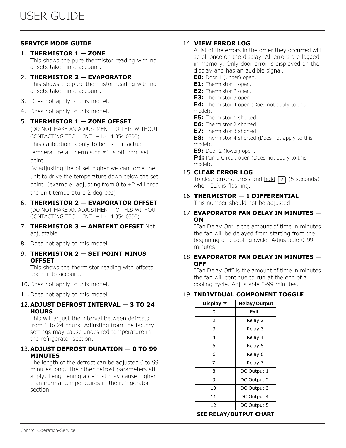
USER GUIDE
Control Operation-Service
USER GUIDE
Control Operation - Service 3
u-line.com
SAFETY • INSTALLATION & INTEGRATION • OPERATING INSTRUCTIONS • MAINTENANCE • SERVICE
SERVICE MODE GUIDE
1. THERMISTOR 1 — ZONE
This shows the pure thermistor reading with no
offsets taken into account.
2. THERMISTOR 2 — EVAPORATOR
This shows the pure thermistor reading with no
offsets taken into account.
3. Does not apply to this model.
4. Does not apply to this model.
5. THERMISTOR 1 — ZONE OFFSET
(DO NOT MAKE AN ADJUSTMENT TO THIS WITHOUT
CONTACTING TECH LINE: +1.414.354.0300)
This calibration is only to be used if actual
temperature at thermistor #1 is off from set
point.
By adjusting the offset higher we can force the
unit to drive the temperature down below the set
point. (example: adjusting from 0 to +2 will drop
the unit temperature 2 degrees)
6. THERMISTOR 2 — EVAPORATOR OFFSET
(DO NOT MAKE AN ADJUSTMENT TO THIS WITHOUT
CONTACTING TECH LINE: +1.414.354.0300)
7. THERMISTOR 3 — AMBIENT OFFSET Not
adjustable.
8. Does not apply to this model.
9. THERMISTOR 2 — SET POINT MINUS
OFFSET
This shows the thermistor reading with offsets
taken into account.
10.Does not apply to this model.
11.Does not apply to this model.
12.ADJUST DEFROST INTERVAL — 3 TO 24
HOURS
This will adjust the interval between defrosts
from 3 to 24 hours. Adjusting from the factory
settings may cause undesired temperature in
the refrigerator section.
13.ADJUST DEFROST DURATION — 0 TO 99
MINUTES
The length of the defrost can be adjusted 0 to 99
minutes long. The other defrost parameters still
apply. Lengthening a defrost may cause higher
than normal temperatures in the refrigerator
section.
# Service Mode Menu Item
1 View thermistor #1 (no offsets)
2 View thermistor #2 (no offsets)
3 View thermistor #3 (no offsets)
4 View thermistor #4 (no offsets)
5 Adjust thermistor #1 offset
6 Adjust thermistor #2 offset
7 Adjust thermistor #3 offset
8 Adjust thermistor #4 offset
9 View thermistor #2 set point no offsets
10 View thermistor #3 set point no offsets
11 View thermistor #4 set point no offsets
12 Adjust defrost interval 3 to 24 hours
13 Adjust defrost duration 0 to 99 minutes
14 View error log
15 Clear error log
16 Adjust thermistor #1 differential
17 Adjust evaporator fan delay in minutes (start of cooling
cycle) 0 - 99 minutes
18 Adjust evaporator fan delay in minutes (after cooling
cycle stops) 0 - 99 minutes
19 Individual component toggle
20 Model number indicator
21 Light all LED segments of display
22 View defrost cycles
23 View compressor run time
24 Activate defrost/harvest
25 Restore factory defaults
26 View software version - main board
27 View software version - user interface
28 Login period
29 Factory test mode
0 Exit service mode
NAVIGATE SERVICE MODE
Use up or down arrows to scroll through the menu.
Use the light bulb key to enter or exit menu. If values
have been changed, they will be saved when exiting.
SERVICE MODE GUIDE
USER GUIDE
Control Operation - Service 4
u-line.com
SAFETY • INSTALLATION & INTEGRATION • OPERATING INSTRUCTIONS • MAINTENANCE • SERVICE
14. VIEW ERROR LOG
A list of the errors in the order they occurred will
scroll once on the display. All errors are logged
in memory. Only door error is displayed on the
display and has an audible signal.
E0:
Door 1 (upper) open.
E1: Thermistor 1 open.
E2: Thermistor 2 open.
E3: Thermistor 3 open.
E4: Thermistor 4 open (Does not apply to this
model).
E5: Thermistor 1 shorted.
E6: Thermistor 2 shorted.
E7: Thermistor 3 shorted.
E8: Thermistor 4 shorted (Does not apply to this
model).
E9: Door 2 (lower) open.
P1: Pump Circuit open (Does not apply to this
model).
15. CLEAR ERROR LOG
To clear errors, press and hold
(5 seconds)
when CLR is flashing.
16. THERMISTOR — 1 DIFFERENTIAL
This number should not be adjusted.
17. EVAPORATOR FAN DELAY IN MINUTES —
ON
“Fan Delay On” is the amount of time in minutes
the fan will be delayed from starting from the
beginning of a cooling cycle. Adjustable
0-99
minutes.
18. EVAPORATOR FAN DELAY IN MINUTES —
OFF
“Fan Delay Off” is the amount of time in minutes
the fan will continue to run at the end of a
cooling cycle. Adjustable 0-99 minutes.
19. INDIVIDUAL COMPONENT TOGGLE
20. MODEL NUMBER INDICATOR
Displays the two-digit model number of the
specific unit. See model list table.
21. LIGHT ALL LED SEGMENTS
This will illuminate all the LEDs on the display to
ensure they work properly.
22. VIEW DEFROST CYCLES
Displays the number of defrosts that have
occurred in the past 24 hours.
23. VIEW COMPRESSOR RUNTIME
This will show the number of minutes the
compressor has run in the prior cycle (or
current cycle if the compressor was running
when service mode was entered).
24. ACTIVATE DEFROST/HARVEST
Turns on the hot gas bypass valve allowing ho
t
gas to circulate through the evaporator causing
frost to melt.
25. RESTORE FACTORY DEFAULTS
Will restore all adjustable functions to thei
r
factory settings.
26. SOFTWARE VERSION — MAIN BOARD
Displays software version of the main control
board.
27. SOFTWARE VERSION —
USER INTERFACE
Displays software version of the user interface.
28. LOG IN PERIOD
Factory use only - do not adjust.
29. FACTORY TEST MODE
Should be 0.
0. EXIT SERVICE MODE
Display # Relay/Output
0 Exit
2 Relay 2
3 Relay 3
4 Relay 4
5 Relay 5
6 Relay 6
7 Relay 7
8 DC Output 1
9 DC Output 2
10 DC Output 3
11 DC Output 4
12 DC Output 5
SEE RELAY/OUTPUT CHART
54
USER GUIDE
Control Operation-Service
USER GUIDE
Control Operation - Service 4
u-line.com
SAFETY • INSTALLATION & INTEGRATION • OPERATING INSTRUCTIONS • MAINTENANCE • SERVICE
14. VIEW ERROR LOG
A list of the errors in the order they occurred will
scroll once on the display. All errors are logged
in memory. Only door error is displayed on the
display and has an audible signal.
E0:
Door 1 (upper) open.
E1: Thermistor 1 open.
E2: Thermistor 2 open.
E3: Thermistor 3 open.
E4: Thermistor 4 open (Does not apply to this
model).
E5: Thermistor 1 shorted.
E6: Thermistor 2 shorted.
E7: Thermistor 3 shorted.
E8: Thermistor 4 shorted (Does not apply to this
model).
E9: Door 2 (lower) open.
P1: Pump Circuit open (Does not apply to this
model).
15. CLEAR ERROR LOG
To clear errors, press and hold (5 seconds)
when CLR is flashing.
16. THERMISTOR — 1 DIFFERENTIAL
This number should not be adjusted.
17. EVAPORATOR FAN DELAY IN MINUTES —
ON
“Fan Delay On” is the amount of time in minutes
the fan will be delayed from starting from the
beginning of a cooling cycle. Adjustable
0-99
minutes.
18. EVAPORATOR FAN DELAY IN MINUTES —
OFF
“Fan Delay Off” is the amount of time in minutes
the fan will continue to run at the end of a
cooling cycle. Adjustable 0-99 minutes.
19. INDIVIDUAL COMPONENT TOGGLE
20. MODEL NUMBER INDICATOR
Displays the two-digit model number of the
specific unit. See model list table.
21. LIGHT ALL LED SEGMENTS
This will illuminate all the LEDs on the display to
ensure they work properly.
22. VIEW DEFROST CYCLES
Displays the number of defrosts that have
occurred in the past 24 hours.
23. VIEW COMPRESSOR RUNTIME
This will show the number of minutes the
compressor has run in the prior cycle (or
current cycle if the compressor was running
when service mode was entered).
24. ACTIVATE DEFROST/HARVEST
Turns on the hot gas bypass valve allowing ho
t
gas to circulate through the evaporator causing
frost to melt.
25. RESTORE FACTORY DEFAULTS
Will restore all adjustable functions to thei
r
factory settings.
26. SOFTWARE VERSION — MAIN BOARD
Displays software version of the main control
board.
27. SOFTWARE VERSION —
USER INTERFACE
Displays software version of the user interface.
28. LOG IN PERIOD
Factory use only - do not adjust.
29. FACTORY TEST MODE
Should be 0.
0. EXIT SERVICE MODE
Display # Relay/Output
0 Exit
2 Relay 2
3 Relay 3
4 Relay 4
5 Relay 5
6 Relay 6
7 Relay 7
8 DC Output 1
9 DC Output 2
10 DC Output 3
11 DC Output 4
12 DC Output 5
SEE RELAY/OUTPUT CHART
55
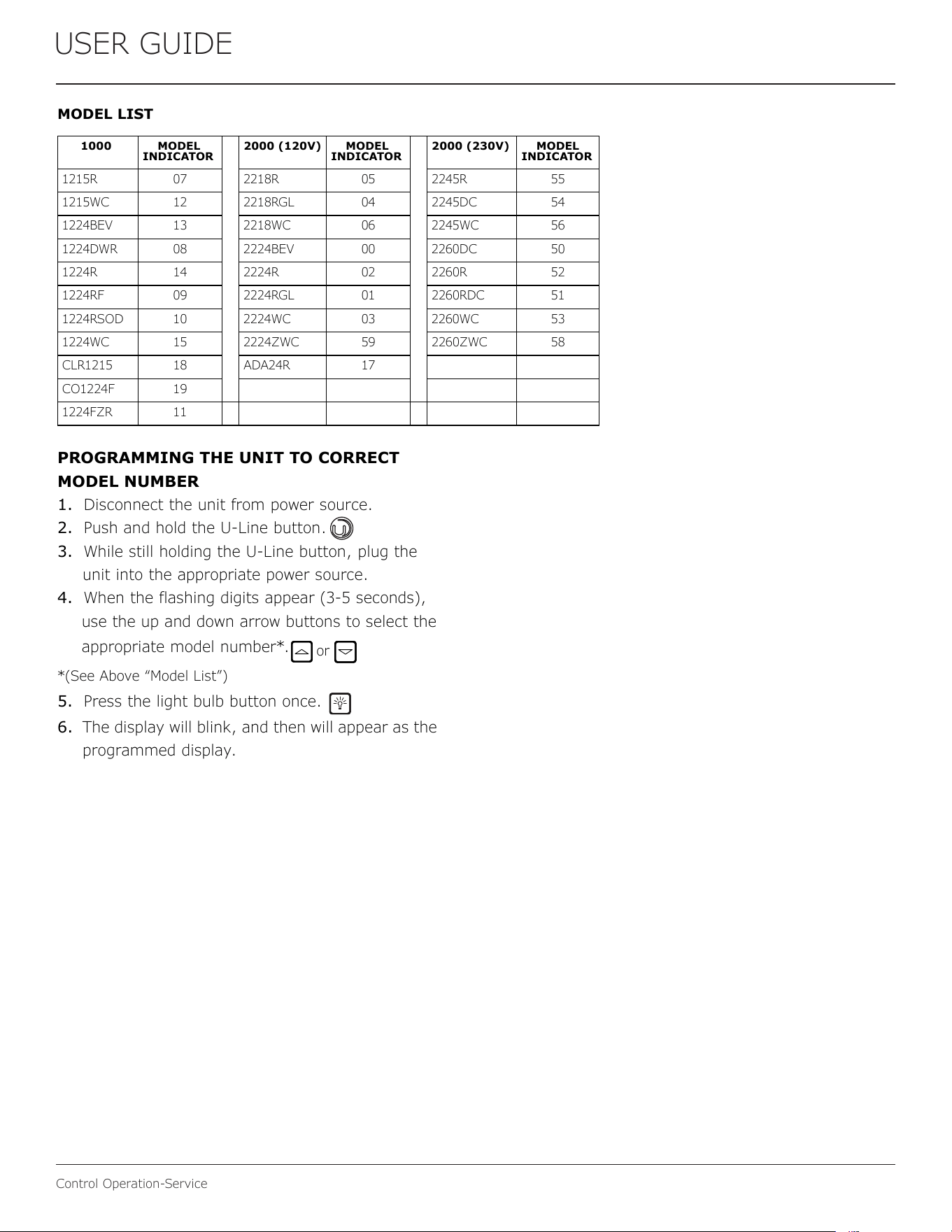
USER GUIDE
Control Operation-Service
USER GUIDE
Control Operation - Service 5
u-line.com
SAFETY • INSTALLATION & INTEGRATION • OPERATING INSTRUCTIONS • MAINTENANCE • SERVICE
MODEL LIST
PROGRAMMING THE UNIT TO CORRECT
MODEL NUMBER
1. Disconnect the unit from power source.
2. Push and hold the U-Line button.
3. While still holding the U-Line button, plug the
unit into the appropriate power source.
4. When the flashing digits appear (3-5 seconds),
use the up and down arrow buttons to select the
appropriat
e model number*.
*(See Above “Model List”)
5. Press the light bulb button once.
6. The display will blink, and then will appear as the
programmed display.
1000 MODEL
INDICATOR
2000 (120V) MODEL
INDICATOR
2000 (230V) MODEL
INDICATOR
1215R 07 2218R 05 2245R 55
1215WC 12 2218RGL 04 2245DC 54
1224BEV 13 2218WC 06 2245WC 56
1224DWR 08 2224BEV 00 2260DC 50
1224R 14 2224R 02 2260R 52
1224RF 09 2224RGL 01 2260RDC 51
1224RSOD 10 2224WC 03 2260WC 53
1224WC 15 2224ZWC 59 2260ZWC 58
CLR1215 18 ADA24R 17
CO1224F 19
1224FZR 11
or
56
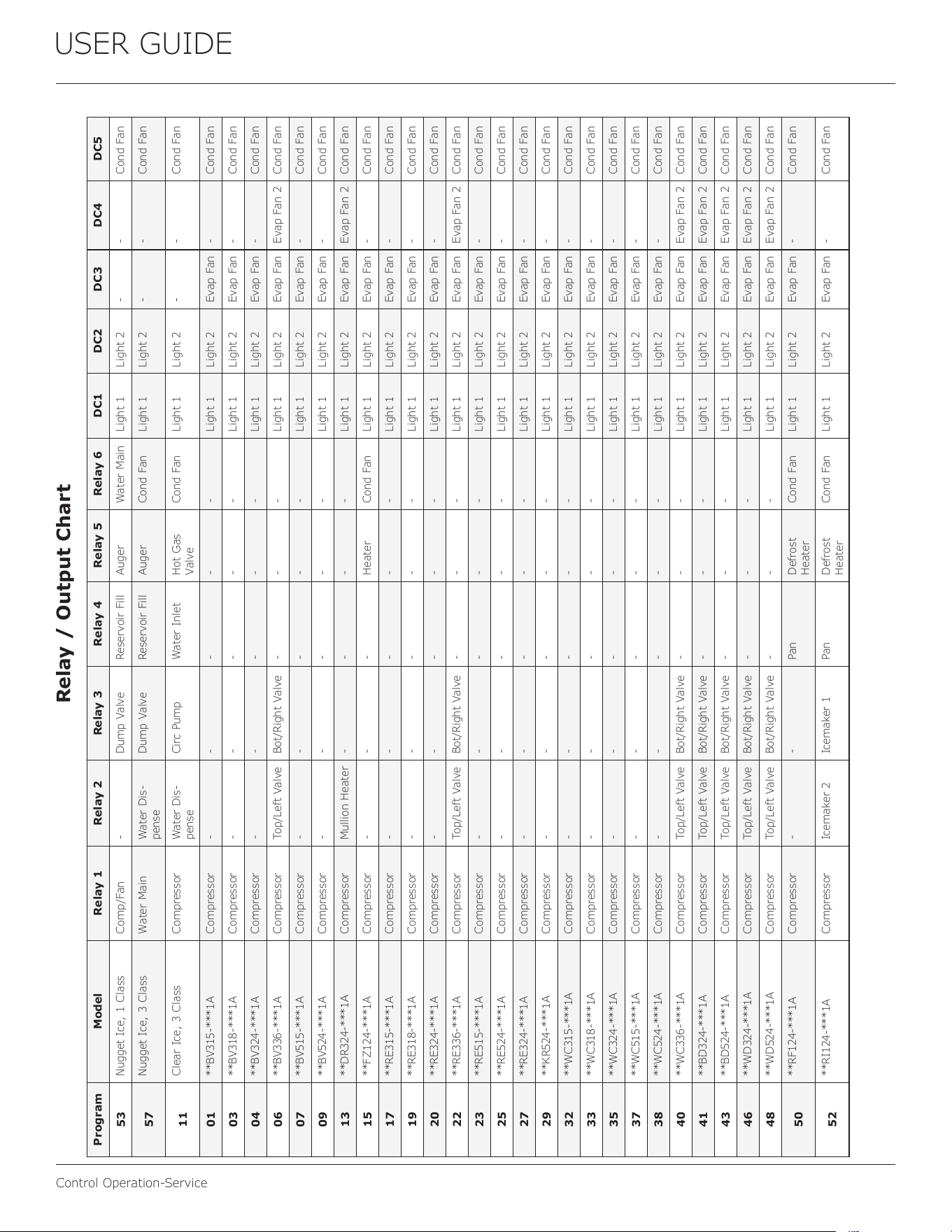
USER GUIDE
Control Operation-Service
Program Model Relay 1 Relay 2 Relay 3 Relay 4 Relay 5 Relay 6 DC1 DC2 DC3 DC4 DC5
53
Nugget Ice, 1 Class Comp/Fan - Dump Valve Reservoir Fill Auger Water Main Light 1 Light 2 - - Cond Fan
57
Nugget Ice, 3 Class Water Main Water Dis-
pense
Dump Valve Reservoir Fill Auger Cond Fan Light 1 Light 2 - - Cond Fan
11
Clear Ice, 3 Class Compressor Water Dis-
pense
Circ Pump Water Inlet Hot Gas
Valve
Cond Fan Light 1 Light 2 - - Cond Fan
01
**BV315-***1A Compressor - - - - - Light 1 Light 2 Evap Fan - Cond Fan
03
**BV318-***1A Compressor - - - - - Light 1 Light 2 Evap Fan - Cond Fan
04
**BV324-***1A Compressor - - - - - Light 1 Light 2 Evap Fan - Cond Fan
06
**BV336-***1A Compressor Top/Left Valve Bot/Right Valve - - - Light 1 Light 2 Evap Fan Evap Fan 2 Cond Fan
07
**BV515-***1A Compressor - - - - - Light 1 Light 2 Evap Fan - Cond Fan
09
**BV524-***1A Compressor - - - - - Light 1 Light 2 Evap Fan - Cond Fan
13
**DR324-***1A Compressor Mullion Heater - - - - Light 1 Light 2 Evap Fan Evap Fan 2 Cond Fan
15
**FZ124-***1A Compressor - - - Heater Cond Fan Light 1 Light 2 Evap Fan - Cond Fan
17
**RE315-***1A Compressor - - - - - Light 1 Light 2 Evap Fan - Cond Fan
19
**RE318-***1A Compressor - - - - - Light 1 Light 2 Evap Fan - Cond Fan
20
**RE324-***1A Compressor - - - - - Light 1 Light 2 Evap Fan - Cond Fan
22
**RE336-***1A Compressor Top/Left Valve Bot/Right Valve - - - Light 1 Light 2 Evap Fan Evap Fan 2 Cond Fan
23
**RE515-***1A Compressor - - - - - Light 1 Light 2 Evap Fan - Cond Fan
25
**RE524-***1A Compressor - - - - - Light 1 Light 2 Evap Fan - Cond Fan
27
**RE324-***1A Compressor - - - - - Light 1 Light 2 Evap Fan - Cond Fan
29
**KR524-***1A Compressor - - - - - Light 1 Light 2 Evap Fan - Cond Fan
32
**WC315-***1A Compressor - - - - - Light 1 Light 2 Evap Fan - Cond Fan
33
**WC318-***1A Compressor - - - - - Light 1 Light 2 Evap Fan - Cond Fan
35
**WC324-***1A Compressor - - - - - Light 1 Light 2 Evap Fan - Cond Fan
37
**WC515-***1A Compressor - - - - - Light 1 Light 2 Evap Fan - Cond Fan
38
**WC524-***1A Compressor - - - - - Light 1 Light 2 Evap Fan - Cond Fan
40
**WC336-***1A Compressor Top/Left Valve Bot/Right Valve - - - Light 1 Light 2 Evap Fan Evap Fan 2 Cond Fan
41
**BD324-***1A Compressor Top/Left Valve Bot/Right Valve - - - Light 1 Light 2 Evap Fan Evap Fan 2 Cond Fan
43
**BD524-***1A Compressor Top/Left Valve Bot/Right Valve - - - Light 1 Light 2 Evap Fan Evap Fan 2 Cond Fan
46
**WD324-***1A Compressor Top/Left Valve Bot/Right Valve - - - Light 1 Light 2 Evap Fan Evap Fan 2 Cond Fan
48
**WD524-***1A Compressor Top/Left Valve Bot/Right Valve - - - Light 1 Light 2 Evap Fan Evap Fan 2 Cond Fan
50
**RF124-***1A Compressor - - Pan Defrost
Heater
Cond Fan Light 1 Light 2 Evap Fan - Cond Fan
52
**RI124-***1A Compressor Icemaker 2 Icemaker 1 Pan Defrost
Heater
Cond Fan Light 1 Light 2 Evap Fan - Cond Fan
Relay / Output Chart
57
Copyright U-Line Corporation. All Rights Reserved. | Publication Number 30379 | 3/2024 Rev. Q
U-Line Corporation (U-Line) Limited Warranty
One Year Limited Warranty
For one year from the date of original purchase, this warranty covers all parts and labor to repair or replace any part of the product that
proves to be defective in materials or workmanship. For products installed and used for normal residential use, material cosmetic defects
are included in this warranty, with coverage limited to 60 days from the date of original purchase. All service provided by U-Line under the
above warranty must be performed by a U-Line factory authorized servicer, unless otherwise specified by U-Line. Service provided during
normal business hours.
Two Year Limited Warranty (5 Class Product)
For two years from the date of original purchase, this warranty covers all parts and labor to repair or replace any part of the product that
proves to be defective in materials or workmanship. For products installed and used for normal residential use, material cosmetic defects
are included in this warranty, with coverage limited to 60 days from the date of original purchase. All service provided by U-Line under the
above warranty must be performed by a U-Line factory authorized servicer, unless otherwise specified by U-Line. Service provided during
normal business hours.
Available Second & Third Year Limited Warranty
In addition to the standard one and two year warranties outlined above, U-Line offers a one year extension of the warranties from the date
of purchase, free of charge. To take advantage of this extension, you must register your product with U-Line within 60 days from the date
of purchase at u-line.com and provide proof of purchase.
Five Year Sealed System Limited Warranty
For five years from the date of original purchase, U-Line will repair or replace the following parts, labor not included, that prove to be
defective in materials or workmanship: compressor, condenser, evaporator, drier, and all connecting tubing. All service provided by U-Line
under the above warranty must be performed by a U-Line factory authorized servicer, unless otherwise specified by U-Line. Service
provided during normal business hours.
Terms
These warranties apply only to products installed in any one of the fifty states of the United States, the District of Columbia, or the ten
provinces of Canada. The warranties do not cover any parts or labor to correct any defect caused by negligence, accident or improper use,
maintenance, installation, service, repair, acts of God, fire, flood or other natural disasters. The product must be installed, operated, and
maintained in accordance with your product’s User Guide.
The remedies described above for each warranty are the only ones that U-Line will provide, either under these warranties or under any
warranty arising by operation of law. U-Line will not be responsible for any consequential or incidental damages arising from the breach of
these warranties or any other warranty, whether express, implied, or statutory. Some states do not allow the exclusion or limitation of
incidental or consequential damages, so the above limitation or exclusion may not apply to you. These warranties give you specific legal
rights, and you may also have other rights which vary from state to state.
Any warranty that may be implied in connection with your purchase or use of the product, including any warranty of merchantability or any
warranty fit for a particular purpose is limited to the duration of these warranties, and only extends to five years in duration for the parts
described in the section related to the five year limited warranty above. Some states do not allow limitations on how long an implied warranty
lasts, so the above limitations may not apply to you.
• The warranties only apply to the original purchaser and are non-transferable.
• The second, third, and five year warranties cover products installed and used for normal residential or designated marine use only.
• The warranties apply to units operated outside only if designed for outdoor use by model and serial number.
• U-Line Commercial products are covered by the one year and 5 year limited warranties and are not eligible for the second and
third year limited warranties.
• Replacement water filters, light bulbs, and other consumable parts are not covered by these warranties.
• The start of U-Line’s obligation is limited to four years after the shipment date from U-Line.
• In-home instruction on how to use your product is not covered by these warranties.
• Food, beverage, and medicine loss are not covered by these warranties.
• If the product is located in an area where U-Line factory authorized service is not available, you may be responsible for a trip
charge or you may be required to bring the product to a U-Line factory authorized service location at your own cost and expense.
• Units purchased after use as floor displays, and/or certified reconditioned units, are covered by the limited one year warranty only
and no coverage is provided for cosmetic defects.
• Signal issues related to Wi-Fi connectivity are not covered by these warranties.
For parts and service assistance, or to find U-Line factory authorized service near you, contact U-Line:
8900 N. 55
th
Street, Milwaukee, WI 53223 • u-line.com • onlineservice@u-line.com • +1.414
.354.0300
58