Loading ...
Loading ...
Loading ...
Part Number 550-142-303/1120
38
EG
/
PEG sEriEs 6
•
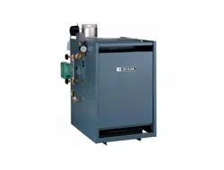
EGH sEriEs 5 Gas-firEd boilErs — boilEr manual
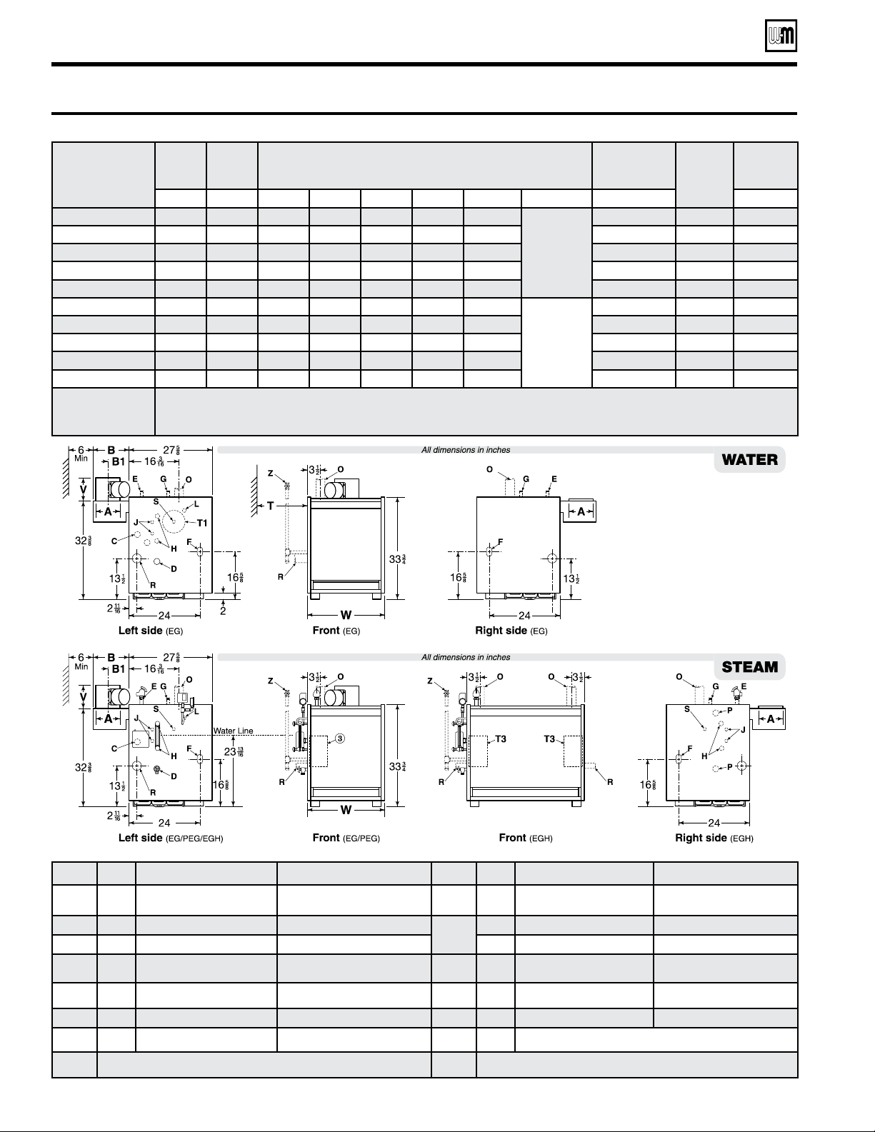
Dimensional data
Table 15 Dimensional data
Tapping Size Steam Boilers Water Boilers - EG only Tapping Size Steam Boilers Water Boilers - EG only
C ¾” Probe type low water cut-off Probe type LWCO (when used)
P
(EGH Only)
1”
Float type LWCO, pressure limit control
and pressure gauge; or LWCO and feeder
combination; or LWCO and pump control
Float type LWCO; or LWCO and feeder
combination; or LWCO and pump control
D ¾” Drain Drain
S
1 ½” Skim tapping Limit control
E ¾” Safety valve Safety relief valve ¾” –– (note 1) Limit control
G ¾” Plugged Piping to compression tank or auto air vent T1
––
––
Optional tankless heater for
water boilers
H ½” Gauge glass and/or optional LWCO Combination pressure temperature gauge
–– –– –– ––
J ⅜” Tri cock tappings Plugged T3
––
Optional steam boiler tankless heater
––
L ½”
Syphon, pressure gauge, high limit
(probe type LWCO)
Combination pressure temperature gauge Z
––
Manual shut-off gas valve (supplied by installer)
Notes: 1. Available on special request only, when tankless heater is specied. Notes: 2. When a tankless water heater coil is installed, use the tapping in the heater for
an additional operating control.
Model
number
Supply
EG/
EGH
Return
EG/
EGH
Dimensions
(See note 3 for PEG-30 to PEG-55 crate dimensions)
Gas
Connection
“F”
Draft
hood
outlet
size
Approx.
ship wt.
O P W A B B1 V
(note 2) T (note 1) (lbs)
EG & PEG-30 & -35
1 - 3” 1 - 2 ½” 17” 5” 11 ¾” 6 ¾” 6”
Water boiler
tankless coil
removal
clearance:
E-624: 14”
E-626: 18”
E-632: 22”
½” 5” 430
EG & PEG-40 & -45
1 - 3” 1 - 2 ½” 21 ¼” 6” 11 ¾” 6 ¾” 6 ½” ½” 6” 505
EG & PEG-50 & -55
1 - 3” 1 - 2 ½” 25 ½” 7” 11 ¾” 6 ¾” 9” ½” 7” 585
EG & PEG-65
1 - 3” 1 - 2 ½” 29 ¾” 8” 11 ¾” 6 ¾” 9 ½” ¾” 8” 660
EG-75
1 - 3” 1 - 2 ½” 34” 8” 15 ¾” 8 ¾” –– ¾” 8” 735
EGH-85
2 - 3” 2 - 2 ½” 38 ¼” 9” 15 ¾” 8 ¾” ––
N/A
¾” 9” 825
EGH-95
2 - 3” 2 - 2 ½” 42 ½” 10” 15 ¾” 8 ¾” –– ¾” 10” 915
EGH-105
2 - 3” 2 - 2 ½” 46 ¾” 10” 15 ¾” 8 ¾” –– 1” 10” 1005
EGH-115
2 - 3” 2 - 2 ½” 51” 12” 15 ¾” 8 ¾” –– 1” 12” 1095
EGH-125
2 - 3” 2 - 2 ½” 55 ¼” 12” 15 ¾” 8 ¾” –– 1” 12” 1185
Notes:
1. Sizes shown are gas connection sizes, natural or liqueed petroleum (propane) gas. Gas piping from meter to boiler to be sized according to local utility requirements. Gas
line can enter on either the right or left end of the boiler.
2. Damper dimension for EG-30 through EG-75 ONLY. For all EGH boilers the damper is additional equipment.
3. PEG crates are 32” wide x 39” high. Crate lengths are 32” for PEG-30, -35, -40; 37” for PEG-45, -50, and -55; 39” for EG-65.
Loading ...
Loading ...